EP3100966B1 - Transfer device - Google Patents
Transfer device Download PDFInfo
- Publication number
- EP3100966B1 EP3100966B1 EP15744073.6A EP15744073A EP3100966B1 EP 3100966 B1 EP3100966 B1 EP 3100966B1 EP 15744073 A EP15744073 A EP 15744073A EP 3100966 B1 EP3100966 B1 EP 3100966B1
- Authority
- EP
- European Patent Office
- Prior art keywords
- unit
- conveying
- main
- conveyer
- sub
- Prior art date
- Legal status (The legal status is an assumption and is not a legal conclusion. Google has not performed a legal analysis and makes no representation as to the accuracy of the status listed.)
- Active
Links
Images











Classifications
-
- B—PERFORMING OPERATIONS; TRANSPORTING
- B65—CONVEYING; PACKING; STORING; HANDLING THIN OR FILAMENTARY MATERIAL
- B65G—TRANSPORT OR STORAGE DEVICES, e.g. CONVEYORS FOR LOADING OR TIPPING, SHOP CONVEYOR SYSTEMS OR PNEUMATIC TUBE CONVEYORS
- B65G47/00—Article or material-handling devices associated with conveyors; Methods employing such devices
- B65G47/52—Devices for transferring articles or materials between conveyors i.e. discharging or feeding devices
- B65G47/53—Devices for transferring articles or materials between conveyors i.e. discharging or feeding devices between conveyors which cross one another
- B65G47/54—Devices for transferring articles or materials between conveyors i.e. discharging or feeding devices between conveyors which cross one another at least one of which is a roller-way
-
- B—PERFORMING OPERATIONS; TRANSPORTING
- B65—CONVEYING; PACKING; STORING; HANDLING THIN OR FILAMENTARY MATERIAL
- B65G—TRANSPORT OR STORAGE DEVICES, e.g. CONVEYORS FOR LOADING OR TIPPING, SHOP CONVEYOR SYSTEMS OR PNEUMATIC TUBE CONVEYORS
- B65G13/00—Roller-ways
- B65G13/02—Roller-ways having driven rollers
- B65G13/06—Roller driving means
- B65G13/07—Roller driving means having endless driving elements
-
- B—PERFORMING OPERATIONS; TRANSPORTING
- B65—CONVEYING; PACKING; STORING; HANDLING THIN OR FILAMENTARY MATERIAL
- B65G—TRANSPORT OR STORAGE DEVICES, e.g. CONVEYORS FOR LOADING OR TIPPING, SHOP CONVEYOR SYSTEMS OR PNEUMATIC TUBE CONVEYORS
- B65G13/00—Roller-ways
- B65G13/08—Roller-ways of curved form; with branch-offs
- B65G13/10—Switching arrangements
-
- B—PERFORMING OPERATIONS; TRANSPORTING
- B65—CONVEYING; PACKING; STORING; HANDLING THIN OR FILAMENTARY MATERIAL
- B65G—TRANSPORT OR STORAGE DEVICES, e.g. CONVEYORS FOR LOADING OR TIPPING, SHOP CONVEYOR SYSTEMS OR PNEUMATIC TUBE CONVEYORS
- B65G15/00—Conveyors having endless load-conveying surfaces, i.e. belts and like continuous members, to which tractive effort is transmitted by means other than endless driving elements of similar configuration
- B65G15/10—Conveyors having endless load-conveying surfaces, i.e. belts and like continuous members, to which tractive effort is transmitted by means other than endless driving elements of similar configuration comprising two or more co-operating endless surfaces with parallel longitudinal axes, or a multiplicity of parallel elements, e.g. ropes defining an endless surface
- B65G15/12—Conveyors having endless load-conveying surfaces, i.e. belts and like continuous members, to which tractive effort is transmitted by means other than endless driving elements of similar configuration comprising two or more co-operating endless surfaces with parallel longitudinal axes, or a multiplicity of parallel elements, e.g. ropes defining an endless surface with two or more endless belts
-
- B—PERFORMING OPERATIONS; TRANSPORTING
- B65—CONVEYING; PACKING; STORING; HANDLING THIN OR FILAMENTARY MATERIAL
- B65G—TRANSPORT OR STORAGE DEVICES, e.g. CONVEYORS FOR LOADING OR TIPPING, SHOP CONVEYOR SYSTEMS OR PNEUMATIC TUBE CONVEYORS
- B65G2207/00—Indexing codes relating to constructional details, configuration and additional features of a handling device, e.g. Conveyors
- B65G2207/18—Crossing conveyors
Definitions
- the present invention relates to a transfer device constituting a part of a conveyer line, and more particularly to a transfer device capable of switching a conveying direction of an object to be conveyed to a direction crossing the conveying direction.
- An object to be handled in a product assembly line or delivered in an conveyed object delivery site is often conveyed on a conveyer line.
- a conveyer line In a delivery site, for example, a large number of conveyer lines are equipped lengthwise and crosswise.
- a transfer device is disposed at each of the cross points of the conveyer lines. The transfer device has a function of transferring an conveyed object from an original conveyer line (main conveyer line) to a different conveyer line (sub conveyer line) for transfer of the conveyed object to a desired position.
- the transfer device includes two conveyer units for conveying an conveyed object, and a lifting and lowering unit for changing a height position of the conveyer units to perform the foregoing function.
- Each of the two conveyer units includes a conveying passage on which an object is placed and conveyed.
- the conveying directions of the conveying passages of the two conveyer units differ from each other. According to this transfer device, relative heights of the two conveying passages are switchable by using the foregoing lifting and lowering unit.
- the lifting and lowering unit of the transfer device of this type retracts a top surface of the conveying passage of the conveyer unit not contributing to conveyance to a position below a conveying surface of the conveyer line, and lifts a top surface of the conveyer unit contributing to conveyance to the conveying surface side of the conveyer line to expose this surface.
- the conveyer unit lifted to the conveying surface side operates (travels) to allow smooth conveyance without obstruction by the conveying unit not contributing to conveyance.
- the transfer device further includes a regulating unit which allows upward and downward movement of each of the two conveyer units in a straight line.
- the regulating unit is a linear guide constituted by an erect pin or shaft, and a bearing member which slides the pin by engagement therewith.
- Patent Document 1 discloses a technology of a transfer device of this type.
- Patent Document 1 discloses a transfer device according to the preamble of claim 1.
- Patent Document 2 discloses a multistage conveyer system which conveys objects on multiple conveyer devices overlapping with each other in the up-down direction.
- Patent Document 3 relates to a roller conveyor including a plurality of idler rollers positioned along and between opposite sidewalls and a transverse drive system operable to rotatably drive at least some of the idler rollers of the roller conveyer.
- the transverse drive system includes a motorized roller positioned generally transverse to the idler rollers and a plurality of drive members drivably connected between the motorized roller and respective ones of the idler rollers. Actuation of the motorized roller drives each of the drive members, which in turn independently rotatably drive the respective idler rollers.
- the transverse drive system may be selectively operable to accumulate articles on one or more zones of the roller conveyor.
- the roller conveyor may include a right angle transfer unit operable to transfer articles in a direction generally normal to the direction of conveyance of the idler rollers.
- the conventional transfer device which constitutes a part of the conveyer line as described above has a great overall height, and therefore increases the height of the entire conveyer line.
- the overall height of the conveyer line equipped with the transfer device is determined based on the height at the portion of the transfer device.
- the height of the main part of the conventional conveyer line only has a length slightly larger than the outside diameter of a roller.
- the main conveyance part is constituted by a belt conveyer, for example, the overall height of the main conveyance part of the conventional conveyer line only has a length slightly larger than the outside diameter of each pulley at both ends.
- the conventional transfer device has a greater overall height than the height of the conveyer of the main conveyance part. Accordingly, the conventional transfer device is difficult to constitute a part of the multistage conveyer system as disclosed in Patent Document 2.
- An object of the present invention is to provide a transfer device having an overall height lower than that of a conventional transfer device.
- a transfer device comprising a main conveying unit having a plurality of main conveying bodies that are adapted to rotate or travel in contact with a conveyed object to convey the object in a fixed direction, a sub conveying unit having a plurality of sub conveying bodies that are adapted to rotate or travel in contact with the conveyed object to carry the object in a direction crossing the conveying direction of the main conveying unit and a lifting and lowering unit having a lifting and lowering mechanism for lifting and lowering at least one of the main conveying unit and the sub conveying unit, and a motor for operating the lifting and lowering mechanism,the lifting and lowering unit are adapted to lifting one of the conveying units to a position above the other conveying unit to convey the object in a desired direction, the main conveying unit and the sub conveying unit being disposed in an identical planar area, wherein a planar position of the motor resides in a planar area overlapping with the main conveying unit and
- a position of a part or the whole of the motor in the height direction is higher than a height of a lowermost end of the rotating bodies, and higher than a height of a lower end of a rotational track or traveling track of the narrow conveyers.
- the conveying bodies of one of the conveying units are constituted by rotating bodies that are rollers or a small rotating body group coaxially arranged.
- the other conveying units are narrow conveyers having a small width.
- the rotating bodies are disposed in parallel in a state that a fixed interval is left between each other.
- the narrow conveyers are disposed between the rotating bodies and appear from the clearances between the rotating bodies. Accordingly, when lifting either the one conveying unit or the other conveying unit, this structure allows the object to be conveyed in the conveying direction of the corresponding conveying unit.
- the position of a part or the whole of the motor in the height direction is higher than the height of the lowermost end of the rotating bodies, and higher than the height of the lower end of the rotational track or traveling track of the narrow conveyers. Accordingly, the overall height of the transfer device can decrease.
- the lifting and lowering unit includes a geared motor, a power transmission shaft transmitted rotational force from the geared motor, a pinion gear attached to the power transmission shaft, and a rack engaging with the pinion gear, an output shaft of the geared motor and the power transmission shaft have a skew positional relationship, the power transmission shaft is disposed below the output shaft of the geared motor, and the rack is formed in a downward direction.
- the output shaft of the geared motor and the power transmission shaft have a skew positional relationship.
- the power transmission shaft is disposed below the output shaft of the geared motor.
- the rack engaging with the pinion gear is formed in the downward direction.
- the geared motor is located at a height overlapping with the rack. Accordingly, the overall height of the transfer device of this aspect decreases.
- the conveying bodies of one of the conveying units are rotating bodies composed of rollers or small rotating body groups coaxially arranged, the rotating bodies are disposed in parallel with a fixed interval, and a driving motor that drives the rotating bodies is disposed in a plane identical to a plane of the respective rotating bodies.
- the conveying bodies of the conveying unit composed of the rotating bodies, and the driving motor are disposed in the identical plane. Accordingly, the overall height of the transfer device can decrease.
- one of the main conveying unit and the sub conveying unit is a roller conveyer device that includes a plurality of rollers disposed in parallel whereas the other conveying unit is a belt conveyer device including a plurality of belt conveyers disposed in parallel, the belts composing the belt conveyer device are disposed between the rollers composing the roller conveyer device, and the motor is disposed in parallel with the rollers of the roller conveyer device, and between the rollers.
- At least one of the main conveying unit and the sub conveying unit includes a regulating unit provided for allowing linear upward and downward movement, and a frame, the regulating unit is a plate body or a linear body that bends and/or tilts, and the regulating unit is attached between the frame and the main conveying unit or the sub conveying unit in such a posture that a bending direction or a tilting direction is aligned with an upward and downward movement direction of the main conveying unit or the sub conveying unit.
- a transfer device in a still further preferable aspect includes a frame, a main conveyer unit having a main conveying passage disposed in a fixed planar area and conveying a conveyed object in a fixed direction, a sub conveyer unit having a sub conveying passage disposed in a planar area identical to the planar area of the main conveying passage and conveying the object in a direction crossing the conveying direction of the main conveying passage, a lifting and lowering unit for lifting or lowering at least one of the main conveyer unit and the sub conveyer unit, the lifting and lowering unit lifting one of the conveying passages to a position above the other conveying passage to convey the object in a desired direction; and a regulating unit provided for allowing linear upward and downward movement of at least one of the main conveyer unit and the sub conveyer unit, wherein the regulating unit is a plate body or a linear body that bends and/or tilts, and wherein the regulating unit is attached between the frame and the main conveyer unit or the sub conveyer unit in such a
- the transfer device in the aspect described above is characterized by including the regulating unit provided for allowing linear upward and downward movement of at least one of the main conveyer unit and the sub conveyer unit, and the frame.
- the regulating unit is a plate body or a linear body that bends and/or tilts.
- the regulating unit is attached between the frame and the main conveyer unit or the sub conveyer unit in such a posture that the bending direction or the tilting direction is aligned with the upward and downward movement direction of the main conveyer unit or the sub conveyer unit.
- the regulating unit is composed of a plate body or a linear body that bends and/or tilts in the fixed direction.
- the regulating unit is attached between the frame and the main conveyer unit or the sub conveyer unit in such a posture that the bending direction or the tilting direction is aligned with the upward and downward movement direction of the main conveyer unit or the sub conveyer unit.
- the regulating unit of the transfer device in this aspect is constituted by a plate body or a linear body which has an extremely low height. This structure allows reduction of the overall design height of the transfer device.
- the regulating unit is a plate body that has elasticity and bends in a fixed direction, and the regulating unit is attached between the frame and the main conveying unit or the sub conveying unit in such a posture that a bending direction is aligned with an upward and downward movement direction of the main conveying unit or the sub conveying unit.
- the regulating unit is composed of a plate body that has elasticity and bends in the fixed direction.
- the regulating unit is attached between the frame and the main conveying unit or the sub conveying unit in such a posture that the bending direction is aligned with the upward and downward movement direction of the main conveying unit or the sub conveying unit.
- the regulating unit bends in a downward convex posture, for example.
- the conveying unit moves downward, the regulating unit bends in an upward convex posture, for example.
- the whole shape of the regulating unit having a plate shape bends in a downward convex posture or an upward convex posture, but does not easily come into a twisted posture.
- This structure allows upward and downward movement of the conveying unit in a straight line.
- the regulating unit composed of a plate body has a considerably low height. This structure therefore reduces the design overall height of the transfer device.
- a plurality of the regulating units are provided between the frame and the main conveying unit or the sub conveying unit.
- the transfer device of this aspect includes the plurality of regulating units. This structure further completely prevents movement of the conveying unit in the planar direction. Moreover, the regulating units each of which is composed of a plate body as described above do not considerably affect the overall height even when the number of the regulating units increases.
- one of the main conveying unit and the sub conveying unit is a roller conveyer device that includes a plurality of rollers disposed in parallel
- the other conveying unit is a belt conveyer device including a plurality of belt conveyers disposed in parallel
- the belts composing the belt conveyer device are disposed between the rollers constituting the roller conveyer device, and tension is constantly applied to the belts by a tensioner.
- one of the conveying units is composed of a belt conveyer device that includes a plurality of belt conveyers disposed in parallel. Tension is constantly applied to the belts by a tensioner. This structure reduces looseness of the belts, therefore facilitating maintenance.
- the planar position of a motor operating a lifting and lowering mechanism resides in a planar area overlapping with a main conveying body and a sub conveying body.
- the motor and respective conveying units overlap with each other in the height direction without interference with each other. Accordingly, the overall height decreases without increasing an occupancy area of the transfer device.
- a transfer device 1 according to an embodiment of the present invention is hereinafter further detailed.
- the transfer device 1 of this embodiment includes a large number of parts. Each of the parts has a shape not only complicated but also tangled.
- the outline and characteristic configurations of the transfer device are initially described. After clarifying these, specific configurations of the respective parts are sequentially explained in detail.
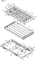
- the transfer device 1 includes a sub conveyer unit (sub conveying unit) 2, a main conveyer unit (main conveying unit) 3, a lifting and lowering unit, and a geared motor 5.
- the transfer device 1 according to this embodiment further includes regulating units 72 and 73 for allowing straight and linear upward and downward movement of the sub conveyer unit 2 and the main conveyer unit 3.
- the sub conveyer unit 2 of the transfer device 1 includes a plurality of conveying rollers 14, and a roller side frame 19 for supporting the conveying rollers 14 such that the conveying rollers 14 are rotatable.
- cam followers 27 are provided at four points of a lower portion of the roller side frame 19. Each of the cam followers 27 is constituted by a short roller.
- the sub conveyer unit 2 is a unit constituted by the roller side frame 19, and the plurality of conveying rollers 14 and the four cam followers 27 combined with the roller side frame 19 into one body.
- At least one of the plurality of conveying rollers 14 is a driving roller, while the others are following rollers. Power is transmitted between the driving roller and the following rollers via belts.
- the driving roller is a motor-incorporating roller which contains a motor and a speed reducer within a roller main body.
- the sub conveyer unit 2 includes a conveying passage constituted by the plurality of conveying rollers 14.
- An conveyed object 25 ( FIG. 1 ), which is an object to be conveyed, placed on the conveying passage is conveyed in accordance with rotation of the conveying rollers 14.
- the driving roller contains the motor for driving the rollers and the speed reducer inside. Accordingly, the driving motor for driving the rollers is disposed in the same plane as the plane of respective rotating bodies (rollers) in this embodiment.
- Movement of the roller side frame 19 in the horizontal direction is regulated by regulating units 73a through 73d. Reciprocating movement of the roller side frame 19 is allowed only in the up-down direction.
- the regulating units 73a through 73d are further detailed below.
- the main conveyer unit 3 includes one belt driving roller 80, a plurality of belt following pulleys 81, annular belts 82 and 88 extending between both the rollers, a belt side frame 18, and a belt conveyer main body 85.
- the belt conveyer main body 85 includes three first narrow belt conveyers 15 (narrow conveyers) each of which has a small width, and one second narrow belt conveyer 30 (narrow conveyer) which has a small width.
- the first narrow belt conveyers 15 and the second narrow belt conveyer 30 are disposed in four parallel lines as illustrated in FIGS. 2 , 3 , and 15 .
- the belt 82 of each of the first narrow belt conveyers 15 has an annular shape. As illustrated in FIG. 30 , each of the belts 82 has a traveling track constituted by a conveying passage side 82a on which the conveyed object 25 ( FIG. 1 ) is placed, and a return side 82b passing below the conveying passage side 82a. Similarly, the belt 88 of the second narrow belt conveyer 30 having an annular shape has a traveling passage constituted by a conveying passage side 88a on which the conveyed object 25 ( FIG. 1 ) is placed, and a return side 88b passing below the conveying passage side 88a.
- the conveying passage side 82a and the return side 82b of each of the first narrow belt conveyers 15 extend in parallel substantially for the overall length in the conveying direction of the main conveyer unit 3 for conveying the conveyed object 25.
- the width of each of the first narrow belt conveyers 15 is substantially uniform in the height direction.
- a narrow part 90 is formed in the vicinity of the center of the second narrow belt conveyer 30 ( FIG. 17 ).
- the second narrow belt conveyer 30 has a substantially U shape including a recessed lower portion produced by the narrow part 90.
- the return side 88b of the belt 88 of the second narrow belt conveyer 30 comes close to the conveying passage side 88a in the area of the narrow part 90 for a predetermined length in the conveying direction of the main conveyer unit 3 for conveying the conveyed object 25.
- the width of the second narrow belt conveyer 30 in the height direction is smaller in the area of the narrow part 90 than in other areas.
- the lower part in the vicinity of the center of the second narrow belt conveyer 30 is recessed to constitute the narrow part 90.
- the narrow part 90 is located in the vicinity of the center of the second narrow belt conveyer 30 and extends in the traveling direction of the belt 82.
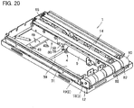
- a space 78 ( FIGS. 20 , 22C and 30 ) is produced between the narrow part 90 of the second narrow belt conveyer 30 and a bottom wall 31 of the main frame 12.
- the space 78 is an area sectioned by the narrow part 90 and the bottom wall 31, and has a larger area in the height direction than that of an area formed between the bottom wall 31 and portions of the second narrow belt conveyer 30 other than the narrow part 90, and a space formed between the bottom wall 31 and each of the first narrow belt conveyers 15.
- the space 78 is formed between the adjoining conveying rollers 14 of the sub conveyer unit 2 within the transfer device 1, and extends in parallel with the conveying rollers 14.
- the space 78 and the respective conveying rollers 14 are disposed in parallel with each other.
- the respective conveying rollers 14 are lifted and lowered on the side of the space 78 by a lifting and lowering mechanism 4. Accordingly, the respective conveying rollers 14 do not enter the space 78.
- the second narrow belt conveyer 30 and the respective first narrow belt conveyers 15 are disposed in parallel with each other.
- the respective first narrow belt conveyers 15 are lifted and lowered on the side of the space 78 by the lifting and lowering mechanism 4.
- the belt 82 of each of the first narrow belt conveyers 15 travels along the traveling track (conveying passage side 82a and return side 82b) in accordance with the belt driving roller 80. Accordingly, the respective belts 82 do not enter the space 78.
- the belt 88 of the second narrow belt conveyer 30 travels on the traveling track (conveying passage side 88a and return side 88b) along the narrow part 90.
- the belt 88 passes through both the ends of the space 78 in the longitudinal direction and above the space 78 in a U shape, while avoiding passage through the space 78. Accordingly, the belt 88 does not enter the space 78.
- the geared motor 5 of the lifting and lowering unit is disposed within the space 78.
- the geared motor 5 is attached in a posture in parallel with the conveying rollers 14 of the sub conveyer units 2 and between the conveying rollers 14.
- the height position of the geared motor 5 disposed in the space 78 is determined such that a part or the whole of the geared motor 5 is located higher than the height of a lower end of a rotational track or traveling track of any one of the conveying bodies (conveying rollers 14 and belts 82 and 88) when any one of the conveying units (main conveyer unit 3 and sub conveyer unit 2) is lowered. Accordingly, the respective heights of the lower ends of the lowered conveying rollers 14, the height of the lower end of the belt 82 of the lowered first narrow belt conveyer 15, and the height of the lower end of the belt 88 of the lowered second narrow belt conveyer 30 are lower than the highest portion of the space 78.
- the geared motor 5 is stored in the space 78 formed inside the transfer device 1. In this case, the geared motor 5 does not collide with the main conveyer unit 3 and the sub conveyer unit 2 moving upward and downward.
- the geared motor 5 and the first narrow belt conveyers 15 of the main conveyer unit 3 do not overlap with each other in the plan view. Accordingly, the belts 82 of the first narrow belts conveyers 15 are lifted and lowered by the lifting and lowering mechanism 4 on the side of the geared motor 5. In this case, the height position of the geared motor 5 exceeds the heights of the lower end portions of the traveling tracks of the belts 82.
- the height position of the geared motor 5 exceeds the height position of the lower end portion of the traveling track of the belt 88 of the main conveyer unit 3 (second narrow belt conveyer 30).
- the lower end portion of the traveling track of the belt 88 in this context corresponds to a portion of the return side 88b other than the narrow part 90.
- the belt 88 extending between a short roller 67a, second and third fixing tension pulleys 60b and 60c, and a short roller 67b is provided along the U-shaped narrow part 90 of a short roller attachment member 59. More specifically, the belt 88 is disposed in a position avoiding the geared motor 5 for the entire length of the geared motor 5 in an area from the front end side (output shaft side) portion to the rear end side portion of the geared motor 5 via an area above the geared motor 5.
- the planar position of the geared motor 5 resides in a planar area overlapping with the second narrow belt conveyer 30 (conveying unit) of the main conveyer unit 3.
- the space 78 formed between the second narrow belt conveyer 30 and the bottom wall 31 of the main frame 12 accommodates the geared motor 5.
- the space 78 is formed along the narrow part 90 of the second narrow belt conveyer 30 as described above.
- the height position of the geared motor 5 exceeds the height position of the lower end of the return side 88b of the belt 88 (conveying body) passing through the portion of the second narrow belt conveyer 30 other than the narrow part 90 in the lowered state.
- the height position of the geared motor 5 is lower than the height of the narrow part 90 of the second narrow belt conveyer 30 in the lowered state, and therefore does not exceed the height position of the lower end of the return side 88b of the belt 88 (conveying body) passing through the narrow part 90. Accordingly, the geared motor 5 and the belt 88 (conveying body) do not interfere with each other even when the main conveyer unit 3 (second narrow belt conveyer 30) lowers.
- the planer position of the geared motor 5 resides in an area overlapping with the sub conveyer unit 2 (conveying unit). In this case, the height position of the geared motor 5 exceeds the height positions of the lower ends of the conveying rollers 14 (conveying bodies) of the sub conveyer unit 2 in the lowered state.
- the lower ends of the conveying rollers 14 are indicated by a two-dot chain line in FIG. 22C .
- the positions of the conveying rollers 14 and the geared motor 5 overlap with each other in the height direction.
- the position of the geared motor 5 is different from the positions of the respective conveying rollers 14 (conveying bodies) in the plan view, and therefore do not interfere with each other.
- the belt conveyer main body 85 of the main conveyer unit 3 which includes the three first narrow belt conveyers 15, and the one second narrow belt conveyer 30.
- the second narrow belt conveyer 30 may be eliminated. More specifically, the second narrow belt conveyer 30 may be eliminated to secure a space for accommodating the geared motor 5 of the lifting and lowering mechanism 4 within the transfer device 1.
- the main conveyer unit 3 constituted by a belt conveyer.
- the main conveyer unit 3 may be a short roller conveyer which includes a plurality of short rollers arranged in the conveying direction of an conveyed object for placing the conveyed object thereon.
- the motor is not limited to the geared motor 5, but may be of any types as long as the motor is rotatable at a low speed, and equipped with an independent speed reducer.
- Cam followers 36 are provided at four points of a lower portion of the belt side frame 18 on the outside thereof. Each of the cam followers 36 is constituted by a short roller.
- the main conveyer unit 3 is a unit which includes the belt side frame 18, and the belt driving roller 80, the plurality of belt following pulleys 81, and the four cam followers 36 combined with the belt side frame 18 into one body.
- the belt driving roller 80 is a motor-incorporating roller which includes a motor (not shown) containing a speed reduction mechanism inside a rotatable outer cylinder. Accordingly, the outer cylinder rotates in accordance with driving of the motor.
- Movement of the belt side frame 18 in the horizontal direction is regulated by the regulating units 72a through 72d.
- the belt side frame 18 is only allowed to reciprocate in the up-down direction.
- the regulating units 72a through 72d are detailed below.
- the main conveyer unit 3 includes conveying passages formed by the belts 82.
- the conveyed object 25 placed on the conveying passages is conveyed in accordance with traveling of the annular belts 82.
- the conveying passages of the main conveyer unit 3, and the conveying passages of the sub conveyer unit 2 are disposed in the same planar area as illustrated in FIGS. 1 , 2 , 23A, 23B , 24A, and 24B . More specifically, the belts 82 of the main conveyer unit 3 are disposed between the conveying rollers 14 of the sub conveyer unit 2 such that the two types of conveyer passages are disposed in the same planar area.
- the lifting and lowering unit is hereinafter described.
- the lifting and lowering unit is constituted by the lifting and lowering mechanism 4 including a plurality of parts combined with each other, and the geared motor 5.
- the lifting and lowering mechanism 4 includes a gear train 52, a power transmission shaft 39, pinion gears 26, horizontal movement members 11, the foregoing cam followers 27 belonging to the sub conveyer unit 2, the foregoing cam followers 36 belonging to the main conveyer unit 3, and others.
- the power transmission shaft 39 is disposed in a direction crossing an output shaft of the geared motor 5.
- the power transmission shaft 39 is located at a skew position with respect to the output shaft of the geared motor 5. More specifically, the height of the power transmission shaft 39 is located below the output shaft (not shown) of the geared motor 5. Both ends of the power transmission shaft 39 come close to the corresponding ends of the transfer device 1.
- the pinion gears 26 are attached to the corresponding ends of the power transmission shaft 39.
- the skew position in this context refers to a positional relationship between two lines not parallel with each other and not crossing each other.
- the power transmission shaft 39 is disposed below and slightly apart from the respective conveying rollers 14 of the main conveyer unit 3 and the belts 82 and 88 of the sub conveyer unit 2 within the transfer device 1.
- the power transmission shaft 39 crosses the respective conveying rollers 14 and the belts 82 and 88 at right angles in the plan view.
- the gear train 52 connects the output shaft of the geared motor 5 and an intermediate portion of the power transmission shaft 39 disposed at skew positions as illustrated in FIG. 5 .
- the gear train 52 transmits rotational force of the geared motor 5 to the power transmission shaft 39. Accordingly, the pinion gears 26 attached to both the ends of the power transmission shaft 39 rotate in accordance with rotation of the geared motor 5.
- the two horizontal movement members 11 are disposed in parallel between the roller side frame 19 and the belt side frame 18.
- a rack 9 is formed in the downward direction in each of the horizontal movement members 11. Reciprocation of the horizontal movement members 11 is allowed only in the longitudinal direction.
- Each of the foregoing pinion gears 26 engages with the corresponding rack 9 formed in the downward direction.
- the power transmission shaft 39 is disposed in a skew position with respect to the output shaft of the geared motor 5, and below the output shaft (not shown) of the geared motor 5.
- the pinion gears 26 provided on the power transmission shaft 39 engage with the racks 9 formed in the downward direction.
- each of the horizontal movement members 11 is constituted by a translation cam which includes a long upper surface 11b.
- the foregoing rack 9 is provided on the lower side of the center of the upper surface 11b.
- Each of the foregoing pinion gears 26 engages with the corresponding rack 9.
- the horizontal movement members 11 reciprocate in the horizontal direction in accordance with transmission of power from the pinion gears 26 performing regular rotation and reverse rotation. More specifically, the horizontal movement members 11 reciprocate in accordance with transmission of power generated by rotation of the foregoing geared motor 5.
- each of the horizontal movement members 11 is constituted by a translation cam.
- Cam recesses 28 and 29 are formed in the upper surface 11b.
- the cam recesses 28 and 29 are formed on one and the other sides of the rack 9, respectively.
- the foregoing cam followers 27 provided on the roller side frame 19, and the foregoing cam followers 36 provided on the belt side frame 18 engage with the cam recesses 28 and 29.
- the four cam followers 36 of the belt side frame 18 drop into the cam recesses 28 and 29 as illustrated in FIGS. 8A through 8C when the horizontal movement member 11 horizontally moves in accordance with rotation of the geared motor 5 and rotation of the pinion gears 26. As a result, the belt side frame 18 lowers, whereby the main conveyer unit 3 moves downward. On the other hand, the sub conveyer unit 2 remains at the lifted position.
- the pinion gears 26 attached to both the ends of the power transmission shaft 39 rotate in accordance with rotation of the geared motor 5.
- the rotation of the pinion gears 26 moves the horizontal movement members 11. Accordingly, the rotation of the geared motor 5 allows alternate lifting and lowering of the main conveyer unit 3 and the sub conveyer unit 2.
- the main conveyer unit 3 and the sub conveyer unit 2 of the transfer device 1 of this embodiment are combined into one unit, and disposed within the main frame 12.
- the main conveyer unit 3 and the main frame 12 are connected only by the four regulating units 72a through 72d.
- the sub conveyer unit 2 and the main frame 12 are connected only by the four regulating units 73a through 73d.
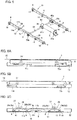
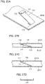
- Each of the regulating units 72 and 73 included in the transfer device 1 of this embodiment is a flat spring.
- Each of the regulating units 72 and 73 is produced by punching a thin plate-shaped spring steel, and is oval-shaped in the plan view as illustrated in FIGS. 10A through 10C . More specifically, each of the regulating units 72 and 73 is constituted by an elliptic thin plate, and has sufficient elasticity to bend in a fixed direction.
- the regulating units 72 and 73 easily bend in the vertical direction with respect to the flat surface.
- the regulating units 72 and 73 exert high resistance to force applied in a twisting direction as indicated by arrows in FIG. 9 , and therefore do not easily become twisted.
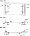
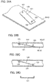
- FIGS. 13A through 13C are explanatory views illustrating models of the main conveyer unit 3 or the sub conveyer unit 2, the main frame 12, and the four regulating units 72 or 73 to explain a relationship between these components.
- a rectangular frame A is a model of the main conveyer unit 3 or the sub conveyer unit 2.
- a plane B is a model of the main frame 12.
- the frame (main conveyer unit 3 or sub conveyer unit 2) and the plane B are connected by the four regulating units 72 or 73. More specifically, one end side of each of the regulating units 72 or 73 is connected to the frame A (main conveyer unit 3 or sub conveyer unit 2), while the other end side of each of the regulating units 72 or 73 is connected to the plane B (main frame 12).
- Each of the regulating units 72 and 73 is a plate body fixed to the frame A and the plane B only by screwing. This structure facilitates assembly of the transfer device 1.
- FIG. 13A illustrates the planar positional relationship between the regulating units 72 or 73.
- Each of frame A side connection portions 200 of the regulating units 72 or 73 is connected to the frame A, while each of plane B side connection portions 201 of the regulating units 72 or 73 is positioned within a planar area surrounded by the frame A.
- a center axial line X-X ( FIG. 10A ) of each of the regulating units 72 or 73 is inclined to each side of the frame A (main conveyer unit 3 or sub conveyer unit 2).
- the center axial lines X-X of the respective regulating units 72 or 73 are inclined to each other, and not in parallel with each other.
- each of the frame A side connection portions 200 of the regulating units 72 or 73 is disposed in the vicinity of the corresponding corner of the frame A.
- the respective regulating units 72 or 73 are disposed in planar postures.
- the flat surfaces of the respective regulating units 72 or 73 are substantially parallel with a virtual plane of the frame A, and a flat surface constituted by the plane B. More specifically, lower surfaces of the respective regulating units 72 or 73 face a flat surface constituted by the main frame 12 as the plane B, while upper surfaces of the respective regulating units 72 or 73 face the virtual plane of the frame A.
- Each of the regulating units 72 or 73 is a plate body having elasticity and bending in a fixed direction, and is attached between the plane B (main frame 12) and the frame A in such a posture that the bending direction of the regulating units 72 or 73 is aligned with the lifting and lowering direction of the frame A (main conveyer unit 3 or sub conveyer unit 2).
- each of the regulating units 72 and 73 is a flat spring easily bending in the vertical direction with respect to the flat surface, but does not easily become twisted.
- the flat surface of each of the regulating units 72 and 73 is substantially parallel with the virtual plane of the frame A and the flat surface constituted by the plane B. Accordingly, when each of the regulating units 72 and 73 is observed, the frame A side connection portion 200 of each of the regulating units 72 and 73 moves in a straight line in the vertical direction with respect to the plane B by bending of the regulating units 72 and 73. More specifically, when the frame A is lifted by the cams, the respective regulating units 72 and 73 bend into a downward convex state to vertically move the frame A without deviation.
- the plurality of (four) regulating units 72 and the plurality of (four) regulating units 73 are attached between the frame A and the plane B. Accordingly, each of the A side connection portions 200 of the regulating units 72 and 73 moves in a straight line in the vertical direction with respect to the plane B.
- the four regulating units 72 and the four regulating units 73 are attached between the frame A and the plane B.
- Each of the frame A side connection portions 200 of the regulating units 72 and 73 is located close to the corresponding corner of the frame A.
- each of the regulating units 72 and 73 has properties not easily twisted. In this case, large force is not required for moving the frame A and the plane B close to and away from each other in parallel.
- reaction force generated between the regulating units 72 and 73 corrects the positions of the frame A and the plane B into parallel postures when the positions of the frame A and the plane B come into inclined positions or twisted positions.
- the respective regulating units 72 and 73 regulate the frame A such that the frame A moves upward and downward in a straight line with respect to the plane B. More specifically, the main conveyer unit 3 and the main frame 12 according to this embodiment are connected to each other only by the four regulating units 72.
- This structure regulates the main conveyer unit 3 such that the main conveyer unit 3 moves in a straight line in the vertical direction with respect to the main frame 12 by operation of the four regulating units 72. More specifically, the regulating units 72 regulate movement of the belt side frame 18 of the main conveyer unit 3 in the horizontal direction. Only reciprocation of the belt side frame 18 in the up-down direction is allowed in this condition.
- This configuration is applicable to the relationship between the sub conveyer unit 2 and the main frame 12.
- the sub conveyer unit 2 and the main frame 12 are connected to each other only by the four regulating units 73.
- This structure regulates the sub conveyer unit 2 such that the sub conveyer unit 2 moves in a straight line in the vertical direction with respect to the main frame 12 by operation of the four regulating units 73. More specifically, the regulating units 73 regulate movement of the roller side frame 19 of the sub conveyer unit 2 in the horizontal direction. Only reciprocation of the roller side frame 19 in the up-down direction is allowed in this condition.
- each of the main conveyer unit 3 and the sub conveyer unit 2 includes the four cam followers 36 or the four cam followers 27.
- the four cam followers 36 and the four cam followers 27 are simultaneously lifted and lowered by the horizontal movement members 11 corresponding to the translation cams. Accordingly, the four cam followers 36 of the main conveyer unit 3 are simultaneously lifted and lowered by the horizontal movement members 11, allowing the main conveyer unit 3 to move upward and downward while maintaining a horizontal posture.
- This configuration is applicable to the sub conveyer unit 2.
- the four cam followers 27 of the sub conveyer unit 2 are simultaneously lifted and lowered by the horizontal movement members 11, allowing the sub conveyer unit 2 to move upward and downward while maintaining a horizontal posture.
- Each of the regulating units 72 and 73 is constituted by a flat spring which is extremely thin, and disposed in parallel with the virtual plane of the main conveyer unit 3 and the virtual plane of the sub conveyer unit 2. Accordingly, each of the respective regulating units 72 and 73 has a planar posture and an extremely small overall height. More specifically, the height of each of the regulating units 72 and 73 is only produced by the thickness of the flat spring, and therefore is considerably smaller than a guide of the conventional technology. Accordingly, the overall height of the transfer device 1 of this embodiment decreases.
- FIGS. 13A through 13C illustrate the frame A as a model of the main conveyer unit 3 or the sub conveyer unit 2, and the plane B as a model of the main frame 12 for describing the function of the regulating units 72 and 73.
- the belt side frame 18 corresponding to a part of the main conveyer unit 3 is smaller than the roller side frame 19 corresponding to a part of the sub conveyer unit 2 as illustrated in FIG. 2 , and is contained within the roller side frame 19. Accordingly, both the frames 18 and 19 are disposed in a common area in the height direction.
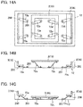
- the four regulating units 72a through 72d illustrated in FIG. 15 are attached between the belt side frame 18 and the main frame 12 to guide the belt side frame 18 in the vertical direction.
- the four regulating units 73a through 73d illustrated in FIG. 21 are attached between the roller side frame 19 and the main frame 12 to guide the roller side frame 19 in the vertical direction.
- a specific configuration of the transfer device 1 according to this embodiment is hereinafter described in more detail.
- the transfer device 1 of this embodiment is disposed at a crossing position of the conveying passages of the conveyer line 21. More specifically, the transfer device 1 is disposed between an upstream side main conveying line 22 and a downstream side main conveying line 23 disposed in a line to constitute a main line 100. A sub conveying line 24 crossing the main conveying lines 22 and 23 at right angles is connected to the transfer device 1.
- the conveyer line 21 conveys the conveyed object 25 along the main line 100 (main conveying lines 22 and 23), or changes the conveying direction on the transfer device 1 to convey the conveyed object 25 along a sub line 101 (sub conveying line 24).
- the transfer device 1 includes the main frame 12 which stores and positions all of the components, the main conveyer unit 3 which conveys the conveyed object 25 ( FIG. 1 ) toward the main conveying line 23 ( FIG. 1 ), and the sub conveyer unit 2 which conveys the conveyed object 25 toward the sub line 101.
- the transfer device 1 further includes the lifting and lowering mechanism 4 as illustrated in FIG. 3 .
- the main frame 12 includes the bottom wall 31, long side walls 32a and 32b, and short side walls 33a and 33b.
- the bottom wall 31 has a rectangular thin plate shape.
- the long side walls 32a and 32b are provided on the long end sides of the bottom wall 31.
- the short side walls 33a and 33b are provided on the short end sides of the bottom wall 31.
- the long side walls 32a and 32b, and short side walls 33a and 33b are connected to each other to constitute a frame surrounding all directions.
- the long side walls 32a and 32b, and the short side walls 33a and 33b are fixed to the bottom wall 31 at right angles.
- Each of the guide members 68 is constituted by a bottom board 68a, a guide rail 68b, and screws 68c.
- the bottom board 68a is a substantially rectangular thin plate component.
- the guide rail 68b is a plate-shaped component which has a length equivalent to the length of the bottom board 68a, and a width smaller than the width of the bottom board 68a.
- the guide rail 68b is disposed at the center of the bottom board 68a. Ends of each of the components 68a and 68b are fixed to the bottom wall 31 by the screws 68c penetrating the components 68a and 68b.
- the upper part of the bottom board 68a on both sides of the guide rail 68b constitutes a rail 69.
- the bottom wall 31 includes four cylindrical fixing portions 34a through 34d, and four cylindrical fixing portions 35a through 35d. A female screw is formed inside each of the cylindrical fixing portions. Only the cylindrical fixing portions 35c and 35d are longer than the others of the eight cylindrical portions.
- each of the regulating units 73a through 73d is fixed to the corresponding one of the four cylindrical fixing portions 34a through 34d of the main frame 12.
- the other ends of the regulating units 73a through 73d are connected to the roller side frame 19 of the sub conveyer unit 2.
- each of the regulating units 72a through 72d is fixed to the corresponding one of the four cylindrical fixing portions 35a through 35d of the main frame 12.
- the other ends of the regulating units 72a through 72d are connected to the belt side frame 18 of the main conveyer unit 3.
- the respective cylindrical fixing portions 34a through 34d and 35a through 35d are joined to the belt side frame 18 and the roller side frame 19 (described below) via the regulating units 72a through 72d and 73a through 73d as illustrated in FIGS. 6A through 6C .
- the lifting and lowering mechanism 4 is provided on the bottom wall 31.
- the lifting and lowering mechanism 4 includes the geared motor 5, the power transmission shaft 39, the horizontal movement members 11, and others.
- a helical gear (not shown) is attached to the output shaft (not shown) of the geared motor 5.
- the geared motor 5 is fixed to the central portion of the bottom wall 31 via fixing members 37a and 37b in such a posture that the output shaft (not shown) faces in the longitudinal direction of the main frame 12.
- a gear box 38 is fixed to the fixing member 37b. The output shaft (not shown) of the geared motor 5 is stored in the gear box 38.
- the power transmission shaft 39 has a length slightly smaller than the length of the bottom wall 31 in the transverse direction.
- a helical gear (not shown) different from the helical gear (not shown) provided on the geared motor 5 is equipped at an intermediate position of the power transmission shaft 39.
- Pinion gears 26a and 26b are provided at one and the other end of the power transmission shaft 39, respectively.
- the power transmission shaft 39 extends in the transverse direction of the main frame 12, and resides at the center of the bottom wall 31. Portions around both the ends of the power transmission shaft 39 are supported by bearing members 40a and 40b.
- the pinion gear 26a is disposed between the two guide members 68 extending along the long side wall 32a.
- the pinion gear 26b is disposed between the two guide members 68 extending along the long side wall 32b.
- the power transmission shaft 39 penetrates the gear box 38 in the direction crossing the output shaft (not shown) of the geared motor 5 at right angles.
- the not-shown helical gear of the power transmission shaft 39 is stored in the gear box 38.
- the helical gear (not shown) on the geared motor 5 side and the helical gear (not shown) on the power transmission shaft 39 side directly or indirectly engage with each other within the gear box 38 to allow power transmission therebetween.
- the power transmission shaft 39 is located below the output shaft (not shown) of the geared motor 5.
- the power transmission shaft 39 and the not-shown output shaft of the geared motor 5 are located in a skew positional relationship.
- each of the horizontal movement members 11 is a long and substantially rectangular parallelepiped component.
- the transverse cross section of each of the horizontal movement members 11 is substantially rectangular.
- Each of the horizontal movement members 11 is disposed within the main frame 12 in such a posture that the longitudinal direction of the rectangular shape of the transverse cross section of the horizontal movement member 11 coincides with the up-down direction.
- a recess is formed at the central portion of a lower surface 11a of each of the horizontal movement members 11.
- the rack 9 is provided in this recess.
- Rack teeth 9a are formed in the rack 9 by an appropriate method such as gear cutting.
- the rack teeth 9a of the rack 9 are formed in the downward direction.
- Each of the four shafts 10 penetrate the side surface of each of the horizontal movement members 11. Each of the four shafts 10 is provided at corresponding one of four points of the horizontal movement member 11 in the longitudinal direction. Two each of the shafts 10 are disposed on one and the other sides of the rack 9, respectively. A pair of guide short rollers 6 are attached to each of the shafts 10.
- the upper surface 11b of each of the horizontal movement members 11 has a plurality of portions having different heights. More specifically, the upper surface 11b of each of the horizontal movement members 11 includes a first low portion 8a (cam recess 28a), a first high portion 7a, a second low portion 8b (cam recess 28b), a second high portion 7b, a third low portion 8c (cam recess 29a), a third high portion 7c, and a fourth low portion 8d (cam recess 29b) in this order from one end.
- the first low portion 8a and the fourth low portion 8d are disposed at one and the other end of the horizontal movement member 11, respectively.
- the second high portion 7b is disposed at the central portion of the horizontal movement member 11 in the longitudinal direction, and constitutes the highest portion of the upper surface 11b.
- the second high portion 7b is formed in the upper surface 11b at the central portion of the horizontal movement member 11 in the longitudinal direction, while the rack 9 is formed in the lower surface 11a below the second high portion 7b.
- the guide short rollers 6 are disposed on the rail 69 of the bottom board 68a of each of the guide members 68.
- the pair of guide short rollers 6 provided on one and the other sides of the guide rail 68b, respectively, are allowed to reciprocate along the guide rail 68b.
- the rack teeth 9a ( FIG. 5 ) of the rack 9 engage with the pinion gears 26a and 26b fixed to the power transmission shaft 39. Accordingly, the horizontal movement members 11 move in the longitudinal direction of the main frame 12 when the geared motor 5 is driven.
- FIG. 6C illustrates a state of engagement between the pinion gear 26a (26b) and the central portion of the rack 9 of the horizontal movement member 11.
- the main conveyer unit 3 includes the belt side frame 18 and the belt conveyer main body 85.
- the belt conveyer main body 85 includes the three first narrow belt conveyers 15 (narrow conveyers) each of which has a small width, and the one second narrow belt conveyer 30 (narrow conveyer) which has a small width.
- the respective belt conveyers 15 and 30 are disposed in four lines in parallel with each other.
- the one belt driving roller 80 is provided as a common driving pulley of the four lines of the narrow belt conveyers. Accordingly, the one belt driving roller 80 (motor-incorporating roller) is provided as a common driving pulley in this embodiment.
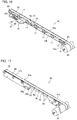
- Each of the first narrow belt conveyers 15 has a configuration illustrated in FIG. 16 .
- a plate-shaped short roller attachment member 16 is provided on one side of the first narrow belt conveyer 15.
- One belt following pulley 81, two fixing tension pulleys 83, and a plurality of short rollers 17 are provided on the short roller attachment member 16.
- the belt 82 having a small width extends between the common driving side pulley (belt driving roller 80) and each of the following pulleys.
- the respective short rollers 17 are disposed within the annular belt 82 to support a load applied to the belt 82. More specifically, the belt driving roller 80 is arranged in the horizontal direction in the same line as the belt following pulley 81, and the plurality of short rollers 17 fixed to the short roller attachment member 16. Accordingly, the overall height of the main conveyer unit 3 decreases.
- the fixing tension pulleys 83 press the belt 82 from the outside.
- the short roller attachment member 16 is a narrow and long plate-shaped component bended in the longitudinal direction into an L shape.
- an auto-tensioner 87 is attached to the belt 82. As illustrated in FIG. 16 , the auto-tensioner 87 is attached to the short roller attachment member 16.
- the auto-tensioner 87 includes a swinging piece 94, a movable tension pulley 84, and a spring 86.
- the short roller attachment member 16 includes a long-hole-shaped spring storage hole, and a spring fixing hole.
- the spring fixing hole is formed at one end of the spring storage hole in the longitudinal direction.
- One end of the spring 86 is fixed to the spring fixing hole of the short roller attachment member 16. Apart of the spring 86 is stored in the spring storage hole.
- the swinging piece 94 is rotatably fixed to the short roller attachment member 16 via a shaft.
- the movable tension pulley 84 is provided at the tip of the swinging piece 94.
- the movable tension pulley 84 is freely rotatable relative to the swinging piece 94.
- the other end of the spring 86 is fixed to a rear end portion of the swinging piece 94.
- the spring 86 connects a spring fixing hole 92b of the short roller attachment member 16 and the rear end portion of the swinging piece 94. Apart of the spring 86 is disposed within a spring storage hole 92a.
- the spring 86 is constituted by a tension spring which pulls the swinging piece 94.
- the spring 86 gives rotational force to the swinging piece 94 around a shaft 93.
- the swinging piece 94 rotates (swings)
- the movable tension pulley 84 fixed to the tip of the swinging piece 94 presses the belt 82.
- appropriate tension is applied to the belt 82.
- the auto-tensioner 87 is a component which includes the movable tension pulley 84 freely rotatable and capable of moving close to and away from the belt 82.
- the short side wall 42b and the short roller attachment member 16 are fixed to each other by screwing.
- the short side wall 42a and the short roller attachment member 16 are fixed to each other by screwing.
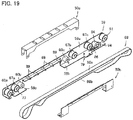
- the second narrow belt conveyer 30 has a configuration illustrated in FIGS. 17 through 19 .
- a plate-shaped short roller attachment member 59 is provide on one side of the second narrow belt conveyer 30.
- the short roller attachment member 59 includes one belt following pulley 81, three fixing tension pulleys 60 (first fixing tension pulley 60a, second fixing tension pulley 60b, and third fixing tension pulley 60c), a plurality of short rollers 67 (67a through 67c), and a plurality of small-diameter short rollers 89.
- the short roller attachment member 59 includes the belt following pulley 81, the three fixing tension pulleys 60, the plurality of short rollers 67, and the plurality of small-diameter short rollers 89 such that these components 81, 60, 67, and 89 are rotatable.
- the three fixing tension pulleys 60 (60a through 60c), the plurality of short rollers 67 (67a through 67c), and the plurality of small-diameter short rollers 89 are disposed between the common driving side pulley (belt driving roller 80) and the belt following pulley 81.
- the belt 88 having a small width extends between the common driving pulley and the belt following pulley 81.
- the short rollers 67a through 67c and the plurality of small-diameter short rollers 89 are disposed within the belt 88 to support a load applied to the belt 88.
- the respective fixing tension pulleys 60a through 60c press the belt 88 from the outside to give tension to the belt 88.
- the narrow part 90 having a small length in the height direction is formed in the short roller attachment member 59.
- the narrow part 90 is disposed in the vicinity of the center of the lower portion of the second narrow belt conveyer 30.
- the narrow part 90 thus formed produces a U-shape of the second narrow belt conveyer 30.
- the plurality of small-diameter short rollers 89 are disposed along the narrow part 90.
- the annular belt 88 passes through the upper conveying passage side 88a and the lower return side 88b both constituting the traveling track.
- the conveyed object 25 ( FIG. 1 ) is placed on the belt 88 passing through the conveying passage side 88a, where a load is applied to the belt 88.
- the respective short rollers 67 (67a through 67c), and the small-diameter short rollers 89 support the load of the conveyed object 25.
- the belt driving roller 80 and the belt following pulley 81 are disposed on one and the other side, respectively.
- the short roller 67a, the plurality of small-diameter short rollers 89, and the short rollers 67b and 67c are disposed within the belt 88 in this order from the belt driving roller 80 side.
- the first fixing tension pulley 60a for pressing the belt 88 from the outside is disposed between the belt driving roller 80 and the short roller 67a.
- the second fixing tension pulley 60b is disposed between the short roller 67a and the small-diameter short rollers 89.
- the third fixing tension pulley 60c is disposed between the small-diameter short rollers 89 and the short roller 67b. Accordingly, the second and third fixing tension pulleys 60b and 60c are disposed on one and the other sides of the plurality of small-diameter short rollers 89, respectively.
- the auto tensioner 87 is further attached to the second narrow belt conveyer 30.
- the auto tensioner 87 has a structure identical to the structure of the auto tensioner 87 of the first narrow belt conveyer 15, and therefore is not repeatedly explained herein.
- the second narrow belt conveyer 30 is fixed to the belt side frame 18 by screwing similarly to the first narrow belt conveyers 15.
- the belt side frame 18 is a frame-shaped component constituted by two long side walls 41a and 41b, and two short side walls 42a and 42b.
- the long side walls 41a and 41b have the same structure except for differences produced by the left hand wall and the right hand wall. Chiefly discussed hereinbelow is the long side wall 41a, and the same explanation concerning the long side wall 41b is not repeated.
- the long side wall 41a is a long flat component, and has a flange shape with the upper side bended at right angles.
- a protrusion 48a protruding downward is provided at one end of the long side wall 41a.
- a protrusion 48b protruding downward is provided in the vicinity of the end opposite to the end on which the protrusion 48a of the long side wall 41a is provided. Protrusion lengths of the protrusions 48a and 48b are substantially equivalent.
- a roller fixing hole 43 is formed in the vicinity of the protrusion 48a of the long side wall 41a.
- Follower fixing holes 44a are formed at two points of the long side wall 41a.
- the follower fixing holes 44a are holes provided for supporting the cam followers 36 such that the cam followers 36 are rotatable.
- the two cam followers 36 are disposed with a predetermined distance left between each other in the longitudinal direction of the long side wall 41a. Both the cam followers 36 are disposed on the outside of the long side wall 41a.
- One of the cam followers 36 is provided at the portion from which the protrusion 48b protrudes.
- each of the short side walls 42a and 42b is a flat component shorter than the long side wall 41a. As illustrated in FIGS. 15 and 25 , respective portions of the short side wall 42a are bended to produce a lower horizontal portion 45a, a vertical portion 45b, and an upper horizontal portion 45c.
- the lower horizontal portion 45a and the upper horizontal portion 45c are disposed on the sides opposite to each other with the vertical portion 45b interposed between the respective portions 45a and 45c.
- Four protrusions 46a and 46d are formed in the upper horizontal portion 45c.
- the respective protrusions 46a through 46d are disposed in the same plane as the plane of the upper horizontal portion 45c, and protrude to the side opposite to the vertical portion 45b.
- the respective protrusions 46a through 46d are sequentially disposed at equal intervals from the end of the upper horizontal portion 45c.
- a hole 47 is formed in the vicinity of each end of the respective protrusions 46a through 46d on the free end side.
- cylindrical fixing portions 70c and 70d are provided on the lower surface sides of the protrusions 46a and 46d, respectively.
- the cylindrical fixing portions 70c and 70d are fixed to the protrusions 46a and 46d by screws penetrating the holes 47.
- a female screw is formed in each inside of the cylindrical fixing portions 70c and 70d.
- One end of the regulating unit 72c is fixed to the cylindrical fixing portion 70c, while one end of the regulating unit 72d is fixed to the cylindrical fixing portion 70d.
- One and the other ends of the short side wall 42a are connected to the tips of the protrusions 48a of the long side walls 41a and 41b, respectively.
- the respective protrusions 46a through 46d of the short side wall 42a are so disposed as to face the center of the long side walls 41a and 41b.
- the lower horizontal portion 45a is disposed on the end side of the long side walls 41a and 41b.
- the short side wall 42b is a narrow and long plate component having the same length as the length of the short side wall 42a.
- the first narrow belt conveyers 15 and the second narrow belt conveyer 30 are fixed by screwing along the long side of the short side wall 42b.
- the frame-shaped belt side frame 18 is constituted by the long side walls 41a and 41b and the short side walls 42a and 42b having the foregoing structures. Both ends of the short side wall 42a (lower horizontal portion 45a) are fixed to the protrusions 48a of the long side walls 41a and 41b, while both ends of the short side wall 42b are fixed to the tip portions of the protrusions 48b protruding downward from the long side walls 41a and 41b. Accordingly, a space 66a is formed below the long side walls 41a and 41b.
- the cam followers 36 are disposed on the outside of the frame of the belt side frame 18.
- the sub conveyer unit 2 includes the roller side frame 19 and a roller conveyer main body 13.
- the roller conveyer main body 13 is disposed on the roller side frame 19.
- At least one of the plurality of conveying rollers 14 of the roller conveyer main body 13 is a driving roller, and the other rollers 14 are following rollers as described above. Power is transmitted between the driving roller and the following rollers via the belts.
- the roller side frame 19 includes two long side walls 51a and 51b, and two short side walls 52a and 52b.
- the long side walls 51a and 51b have the same structure except for differences produced by the left hand wall and the right hand wall. Chiefly discussed hereinbelow is the long side wall 51a, and the same explanation concerning the long side wall 51b is not repeated.
- the roller side frame 19 is a frame-shaped component constituted by the long side walls 51a and 51b, and the short side walls 52a and 52b.
- the roller side frame 19 is slightly larger than the belt side frame 18, and capable of storing the belt side frame 18 inside.
- the long side wall 51a is constituted by a long flat component.
- the upper side of the long side wall 51a is bended at right angles to form a flange shape.
- Follower fixing holes 54a are formed at two points of the long side wall 51a.
- the follower fixing holes 54a are holes provided for supporting the cam followers 27 (depicted in long side wall 51b) such that the cam followers 27 are rotatable.
- the two cam followers 27 are disposed with a predetermined distance in the longitudinal direction of the long side wall 51a. Both the cam followers 27 are located in a portion deviated from the center of the long side wall 51a.
- Each of the short side walls 52a and 52b is a flat component shorter than the long side wall 51a.
- the short side wall 52a has a structure of a flat plate bended into a substantially U shape.
- the short side wall 52a includes a bottom wall 55a, and vertical walls 55b and 55c.
- the vertical walls 55b and 55c rise from one and the other sides of the bottom wall 55a, respectively.
- the vertical wall 55c has a larger rising height from the bottom wall 55a than the corresponding height of the vertical wall 55b.
- fixing holes 76a and 76b are formed in the vicinity of one and the other end of the bottom wall 55a in the longitudinal direction.
- Protrusions 56a through 56e protruding upward are provided on an upper edge portion of the vertical wall 55c.
- the respective protrusions 56a through 56e are disposed at predetermined equal intervals.
- the second protrusion 56b from the end has a larger protrusion length than the corresponding lengths of the other protrusions.
- the second protrusion 56b is bended at right angles in a direction away from the bottom portion 55a to produce a horizontal portion 53, and is further bended at the horizontal portion 53 to extend in the vertical direction.
- the heights of the respective protrusions 56a through 56e are uniform.
- a hole 57 is formed in the vicinity of each tip of the protrusions 56a through 56e.
- Vertical walls 58 are provided at one and the other end of the short side wall 52a in the longitudinal direction.
- the vertical walls 58 are shorter than the respective protrusions 56a through 56e.
- the short side wall 52b is composed of a plate-shaped component having substantially the same length as the length of the short side wall 52a.
- the short side wall 52b is bended in the longitudinal direction to produce a bottom wall 61a and a vertical wall 61b.
- Two fixing holes 62a and 62b are formed in the bottom wall 61a with a predetermined distance.
- Notches 65a through 65e are formed in the upper side of the vertical wall 61b at equal intervals.
- the notches 65a through 65e produce protrusions 63a through 63d protruding upward from the upper side portion of the vertical wall 61b.
- Connection walls 64 continuing from the vertical wall 61b are provided at one and the other ends of the short side wall 52b, respectively.
- Each of the connection walls 64 includes side walls 64a and 64b crossing each other at right angles.
- the side wall 64a is connected to the vertical wall 61b at right angles.
- the width of the bottom wall 61a is equivalent to the width of the side wall 64a.
- the side wall 64a is bended with respect to the vertical wall 61b in the same direction as the direction of the bottom wall 61a.
- the side wall 64b crosses the side wall 64a at right angles, and extends to the side where the bottom wall 61a is not present.
- the roller side frame 19 is a frame-shaped component which includes the long side walls 51a and 51b facing each other.
- One end of the long side wall 51a and one end of the long side wall 51b are connected with each other via the short side wall 52a, while the other end of the long side wall 51a and one end of the long side wall 51b are connected with each other via the short side wall 52b.
- the lower portion of one end of the long side wall 51a and the lower portion of one end of the long side wall 51b are connected to the vertical walls 58 on one and the other sides of the short side wall 52a, respectively.
- the other end of the long side wall 51a and the other end of the long side wall 51b are connected to the side walls 64b of the connection walls 64 on one and the other sides of the short side wall 52b, respectively. Accordingly, a space 66b is formed below the connection walls 64 and the long side walls 51a and 51b.
- the cam followers 27 are rotatably fixed to the long side walls 51a and 51b in a state where the cam followers 27 are floating in the air above the space 66b.
- the cam followers 27 are disposed inside the frame of the roller side frame 19.
- the main frame 12 and the belt side frame 18 are connected to each other via the four regulating units 72a through 72d (flat springs).
- Each of the regulating units 72a through 72d is composed of a narrow and long thin plate component which has both rigidity and elasticity. As illustrated in FIG. 9 , the holes 74 and 75 are formed in the vicinity of one and the other ends of each of the regulating units 72a through 72d.
- the main frame 12 and the roller side frame 19 are connected with each other via the four regulating units 73a through 73d (flat springs).
- the regulating units 73a through 73d are components having configurations identical to the configurations of the regulating units 72a through 72d.
- the holes 74 and 75 are formed in the vicinity of one and the other ends, respectively, of each of the regulating units 73a through 73d.
- the short side wall 52a of the roller side frame 19 is connected to the main frame 12 via the regulating units 73c and 73d. More specifically, the fixing hole 76a of the short side wall 52a and the hole 74 of the regulating unit 73c are aligned, and fixed to each other by a bolt and a nut. Moreover, the cylindrical fixing portion 34c of the main frame 12 and the hole 75 of the regulating unit 73c are aligned, and fixed to each other by a bolt and a nut as illustrated in FIG. 26 .
- the regulating unit 73c is fixed to the fixing hole 76a of the short side wall 52a, and the cylindrical fixing portion 34c of the main frame 12. Similarly, the regulating unit 73d is fixed to the fixing hole 76b of the short side wall 52a, and the cylindrical fixing portion 34d of the main frame 12.
- the short side wall 52b of the roller side frame 19 is connected to the main frame 12 via the regulating units 73a and 73b illustrated in FIG. 21 . More specifically, the regulating units 73a and 73b are fixed to the fixing holes 62a and 62b of the short side wall 52b, and the cylindrical fixing units 34a and 34b ( FIG. 4 ) of the main frame 12, respectively.
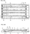
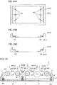
- the transfer device 1 in a state of assembly of the respective components described above has a planar shape as illustrated in FIG. 22A , and a front shape as illustrated in FIG. 22B .
- FIGS. 23A and 23B and FIGS. 24A and 24B The positional relationship between the regulating units 72 and 73 is illustrated in FIGS. 23A and 23B and FIGS. 24A and 24B .
- the eight regulating units 72 and 73 are disposed away from each other in the plan view. Accordingly, the main conveyer unit 3 and the sub conveyer unit 2 can be smoothly lifted and lowered without collision between the regulating units 72 and 73 in a bended state of the regulating units 72 and 73.
- the eight regulating units 72 and 73 reside in the same area in the height direction as illustrated in FIGS. 23B and 24B . Moreover, each height of the eight regulating units 72 and 73 is small. Accordingly, the overall height of the transfer device 1 decreases.
- the transfer device 1 In setting the conveying direction of the conveyed object 25 illustrated in FIG. 1 , the transfer device 1 is operated in the following manner.
- the main conveyer unit 3 of the transfer device 1 For conveying the conveyed object 25 from the upstream side main conveying line 22 to the downstream side main conveying line 23, the main conveyer unit 3 of the transfer device 1 is lifted to position the belts 82 and 88 on the conveying passage, while the sub conveyer unit 2 is lowered to retract the conveying rollers 14 to an area below the conveying passage.
- the horizontal movement members 11 are moved rightward by driving the geared motor 5 to position the cam followers 36 of the main conveyer unit 3 on the first high portion 7a and the third high portion 7c, and position the cam followers 27 of the sub conveyer unit 2 on the first low portion 8a (cam recess 28a) and the third low portion 8c (cam recess 29a) as illustrated in FIG. 7C .
- the main conveyer unit 3 moves to a lifted position, while the sub conveyer unit 2 moves to a lowered position.
- the belts 82 and 88 are positioned on the conveying surface, and thus the conveyed object 25 is conveyed toward the downstream side main conveying line 23 by the main conveyer unit 3 of the transfer device 1.
- the respective regulating units 72 and 73 guide the respective main conveyer unit 3 and the sub conveyer unit 2 in the vertical direction as illustrated in FIGS. 7A and 7B .
- the sub conveyer unit 2 of the transfer device 1 For conveying the conveyed object 25 from the upstream side main conveying line 22 to the sub conveying line 24, the sub conveyer unit 2 of the transfer device 1 is lifted to position the conveying rollers 14 on the conveying passage, while the main conveyer unit 3 is lowered to retract the belts 82 and 88 to an area below the conveying passage.
- the horizontal movement members 11 are moved leftward by driving the geared motor 5 to position the cam followers 36 of the main conveyer unit 3 on the second low portion 8b (cam recess 28a) and the fourth low portion 8d (cam recess 29b), and position the cam followers 27 of the sub conveyer unit 2 on the first high portion 7a and the third high portion 7c as illustrated in FIG. 8C .
- the main conveyer unit 3 moves to a lowered position, while the sub conveyer unit 2 moves to a lifted position.
- the conveying rollers 14 are positioned on the conveying surface, and thus the conveyed object 25 is conveyed toward the sub conveying line 24 by the sub conveyer unit 2 of the transfer device 1.
- the respective regulating units 72 and 73 guide the respective main conveyer unit 3 and the sub conveyer unit 2 in the vertical direction as illustrated in FIGS. 8A and 8B .
- each of the regulating units 72 and 73 is composed of a flat spring.
- the sub conveyer unit 2 and the main conveyer unit 3 are guided to linearly move upward and downward in a straight line by utilizing bending of the elastic flat springs.
- a tiltable plate body may be employed in place of each of the flat springs.
- FIGS. 27A through 27D illustrate an example of a tiltable plate body 111 employed as a regulating unit 110.
- the main body of the regulating unit 110 corresponds to the plate body 111 which has small elasticity and does not easily bend.
- both ends of the regulating unit 110 are connected to the frame A (main conveyer unit 3 or sub conveyer unit 2) and the plane B (main frame 12) via hinges 112 and 113. Accordingly, the regulating unit 110 comes into either a substantially horizontal posture as illustrated in FIG. 27B , or a tilted posture as illustrated in FIG. 27C .
- There is certain backlash between the hinges 112 and 113 This backlash absorbs a change of the distance between the hinges 112 and 113 in the longitudinal direction resulting from a change into the tilted posture of the plate body 111.
- the regulating unit 110 is a plate body which is tiltable in the vertical direction with respect to the flat surface, but is not easily twisted. Moreover, the flat surface of each of the regulating units 110 extends substantially in parallel with the virtual plane of the frame A, and the flat surface constituted by the plane B. Accordingly, as observed for each of the regulating units 110, the frame A can move in a straight line in the vertical direction with respect to the plane B in accordance with tilts of the regulating units 110. More specifically, tilts of the respective regulating units 110 can move the frame A vertically without deviation when the frame A is lifted by the cams.
- Each of the regulating units 110 is composed of a plate body and not required to bend.
- each of the regulating units 110 may have a U-shaped cross section as illustrated in FIG. 27D . Accordingly, each of the regulating units 110 is not required to have a flat shape.
- a regulating unit 120 illustrated in FIGS. 28A through 28D also includes a tiltable plate body 121. However, this example does not include a hinge.
- a main body of the regulating unit 120 corresponds to a plate body 121 which has small elasticity and does not easily bend.
- holes 126 and 127 are formed at one and the other ends of the regulating unit 120.
- Connection elements 123 and 125 composed of pins or screws are inserted into the holes 126 and 127, and connected to the frame A (main conveyer unit 3 or sub conveyer unit 2) and the plane B (main frame 12).
- the holes 126 and 127 formed at one and the other ends of the regulating unit 120 are larger than the connection elements 123 and 125 constituted by pins or screws. Moreover, the connection elements 123 and 125 only slightly fix both the ends of the regulating unit 120.
- the regulating unit 120 is allowed to come into a substantially horizontal posture as illustrated in FIG. 28B , and a tilted posture as illustrated in FIG. 28C .
- the regulating unit 120 is constituted by a plate body and not required to bend.
- the regulating units 120 may have a U-shaped cross section as illustrated in FIG. 28D . Accordingly, the regulating unit 120 is not required to have a flat shape.
- a linear component may be employed to constitute a regulating unit 130.
- FIGS. 29A through 29C illustrate the regulating unit 130 constituted by a linear material such as piano wire.
- the regulating unit 130 employed in this embodiment is composed of a linear material such as piano wire, and has elasticity in a bending direction.
- the frame A (main conveyer unit 3 or sub conveyer unit 2) is connected to the plane B by a large number of the regulating units 130.
- the frame A is allowed to move in a straight line in the vertical direction with respect to the plane B also in this embodiment. More specifically, tilts of the respective regulating units 130 can move the frame A vertically without deviation when the frame A is lifted by the cams.
Landscapes
- Engineering & Computer Science (AREA)
- Mechanical Engineering (AREA)
- Relays Between Conveyors (AREA)
- Intermediate Stations On Conveyors (AREA)
Description
- The present invention relates to a transfer device constituting a part of a conveyer line, and more particularly to a transfer device capable of switching a conveying direction of an object to be conveyed to a direction crossing the conveying direction.
- An object to be handled in a product assembly line or delivered in an conveyed object delivery site is often conveyed on a conveyer line. In a delivery site, for example, a large number of conveyer lines are equipped lengthwise and crosswise. A transfer device is disposed at each of the cross points of the conveyer lines. The transfer device has a function of transferring an conveyed object from an original conveyer line (main conveyer line) to a different conveyer line (sub conveyer line) for transfer of the conveyed object to a desired position.
- The transfer device includes two conveyer units for conveying an conveyed object, and a lifting and lowering unit for changing a height position of the conveyer units to perform the foregoing function. Each of the two conveyer units includes a conveying passage on which an object is placed and conveyed. The conveying directions of the conveying passages of the two conveyer units differ from each other. According to this transfer device, relative heights of the two conveying passages are switchable by using the foregoing lifting and lowering unit.
- The lifting and lowering unit of the transfer device of this type retracts a top surface of the conveying passage of the conveyer unit not contributing to conveyance to a position below a conveying surface of the conveyer line, and lifts a top surface of the conveyer unit contributing to conveyance to the conveying surface side of the conveyer line to expose this surface. In this condition, the conveyer unit lifted to the conveying surface side operates (travels) to allow smooth conveyance without obstruction by the conveying unit not contributing to conveyance.
- The transfer device further includes a regulating unit which allows upward and downward movement of each of the two conveyer units in a straight line.
- In general, the regulating unit is a linear guide constituted by an erect pin or shaft, and a bearing member which slides the pin by engagement therewith.
- For example,
Patent Document 1 discloses a technology of a transfer device of this type.Patent Document 1 discloses a transfer device according to the preamble ofclaim 1. - In addition,
Patent Document 2 discloses a multistage conveyer system which conveys objects on multiple conveyer devices overlapping with each other in the up-down direction. -
Patent Document 3 relates to a roller conveyor including a plurality of idler rollers positioned along and between opposite sidewalls and a transverse drive system operable to rotatably drive at least some of the idler rollers of the roller conveyer. The transverse drive system includes a motorized roller positioned generally transverse to the idler rollers and a plurality of drive members drivably connected between the motorized roller and respective ones of the idler rollers. Actuation of the motorized roller drives each of the drive members, which in turn independently rotatably drive the respective idler rollers. The transverse drive system may be selectively operable to accumulate articles on one or more zones of the roller conveyor. The roller conveyor may include a right angle transfer unit operable to transfer articles in a direction generally normal to the direction of conveyance of the idler rollers. -
- Patent Document 1:
JP 2012-051 679 A - Patent Document 2:
JP 2001-225 946 A -
Patent Document 3:
US 2005/040016 A1 - There is a problem arising from the conventional transfer device and desired to be solved, in the point that the overall height of the transfer device is higher than heights of other parts of the conveyer line.
- More specifically, the conventional transfer device which constitutes a part of the conveyer line as described above has a great overall height, and therefore increases the height of the entire conveyer line. In this case, the overall height of the conveyer line equipped with the transfer device is determined based on the height at the portion of the transfer device.
- When a part of the conveyer line (main conveyance part) other than the transfer device is constituted by a roller conveyer, for example, the height of the main part of the conventional conveyer line only has a length slightly larger than the outside diameter of a roller. When the main conveyance part is constituted by a belt conveyer, for example, the overall height of the main conveyance part of the conventional conveyer line only has a length slightly larger than the outside diameter of each pulley at both ends.
- However, the conventional transfer device has a greater overall height than the height of the conveyer of the main conveyance part. Accordingly, the conventional transfer device is difficult to constitute a part of the multistage conveyer system as disclosed in
Patent Document 2. - The present invention has been developed in consideration of the aforementioned problems arising from the conventional technology. An object of the present invention is to provide a transfer device having an overall height lower than that of a conventional transfer device.
- For achieving the above object, a transfer device is provided according to
independent claim 1, namely a transfer device comprising a main conveying unit having a plurality of main conveying bodies that are adapted to rotate or travel in contact with a conveyed object to convey the object in a fixed direction, a sub conveying unit having a plurality of sub conveying bodies that are adapted to rotate or travel in contact with the conveyed object to carry the object in a direction crossing the conveying direction of the main conveying unit and a lifting and lowering unit having a lifting and lowering mechanism for lifting and lowering at least one of the main conveying unit and the sub conveying unit, and a motor for operating the lifting and lowering mechanism,the lifting and lowering unit are adapted to lifting one of the conveying units to a position above the other conveying unit to convey the object in a desired direction, the main conveying unit and the sub conveying unit being disposed in an identical planar area, wherein a planar position of the motor resides in a planar area overlapping with the main conveying unit and also resides in a planar area overlapping with the sub conveying unit, and wherein a position of the motor in a height direction is set such that a part or the whole of the motor is located above a height of a lower end of a rotational track or a traveling track of any one of the conveying bodies of any one of the conveying units in a lowered state, wherein one of the main conveying unit and the sub conveying unit is a roller conveyer device that includes a plurality of rollers disposed in parallel whereas the other conveying unit is a belt conveyer device including a plurality of belts disposed in parallel, wherein the belts composing the belt conveyer device are disposed between the rollers composing the roller conveyer device, wherein a traveling track of each of the belts comprises a conveying passage side on which the conveyed object is placed, and a return side that passes below the conveying passage side,wherein a narrow part coming close to the conveying passage side is formed in the return side of at least one of the belts for a predetermined length in the conveying direction of the conveyed object, and wherein the motor is disposed at the narrow part. Optional modifications are outlined in the dependent claims and in the following description as preferable aspects. Only those examples that comprise all the features of the independent claim are part of the invention and thus embodiments of the invention. Parts of the subject-matter of the description not covered by the claims constitute background art or examples useful for understanding the invention.
In a preferable aspect a position of a part or the whole of the motor in the height direction is higher than a height of a lowermost end of the rotating bodies, and higher than a height of a lower end of a rotational track or traveling track of the narrow conveyers. - According to the transfer device of this aspect, the conveying bodies of one of the conveying units are constituted by rotating bodies that are rollers or a small rotating body group coaxially arranged. The other conveying units are narrow conveyers having a small width. The rotating bodies are disposed in parallel in a state that a fixed interval is left between each other.
- The narrow conveyers are disposed between the rotating bodies and appear from the clearances between the rotating bodies. Accordingly, when lifting either the one conveying unit or the other conveying unit, this structure allows the object to be conveyed in the conveying direction of the corresponding conveying unit.
- Moreover, the position of a part or the whole of the motor in the height direction is higher than the height of the lowermost end of the rotating bodies, and higher than the height of the lower end of the rotational track or traveling track of the narrow conveyers. Accordingly, the overall height of the transfer device can decrease.
- In a preferable aspect, the lifting and lowering unit includes a geared motor, a power transmission shaft transmitted rotational force from the geared motor, a pinion gear attached to the power transmission shaft, and a rack engaging with the pinion gear, an output shaft of the geared motor and the power transmission shaft have a skew positional relationship, the power transmission shaft is disposed below the output shaft of the geared motor, and the rack is formed in a downward direction.
- According to the transfer device of this aspect, the output shaft of the geared motor and the power transmission shaft have a skew positional relationship. The power transmission shaft is disposed below the output shaft of the geared motor. The rack engaging with the pinion gear is formed in the downward direction. In this case, the geared motor is located at a height overlapping with the rack. Accordingly, the overall height of the transfer device of this aspect decreases.
- In a preferable aspect, the conveying bodies of one of the conveying units are rotating bodies composed of rollers or small rotating body groups coaxially arranged, the rotating bodies are disposed in parallel with a fixed interval, and a driving motor that drives the rotating bodies is disposed in a plane identical to a plane of the respective rotating bodies.
- According to the transfer device of this aspect, the conveying bodies of the conveying unit composed of the rotating bodies, and the driving motor are disposed in the identical plane. Accordingly, the overall height of the transfer device can decrease.
- In a preferable aspect, one of the main conveying unit and the sub conveying unit is a roller conveyer device that includes a plurality of rollers disposed in parallel whereas the other conveying unit is a belt conveyer device including a plurality of belt conveyers disposed in parallel, the belts composing the belt conveyer device are disposed between the rollers composing the roller conveyer device, and the motor is disposed in parallel with the rollers of the roller conveyer device, and between the rollers.
- In a preferable aspect, at least one of the main conveying unit and the sub conveying unit includes a regulating unit provided for allowing linear upward and downward movement, and a frame, the regulating unit is a plate body or a linear body that bends and/or tilts, and the regulating unit is attached between the frame and the main conveying unit or the sub conveying unit in such a posture that a bending direction or a tilting direction is aligned with an upward and downward movement direction of the main conveying unit or the sub conveying unit.
- A transfer device in a still further preferable aspect includes a frame, a main conveyer unit having a main conveying passage disposed in a fixed planar area and conveying a conveyed object in a fixed direction, a sub conveyer unit having a sub conveying passage disposed in a planar area identical to the planar area of the main conveying passage and conveying the object in a direction crossing the conveying direction of the main conveying passage, a lifting and lowering unit for lifting or lowering at least one of the main conveyer unit and the sub conveyer unit, the lifting and lowering unit lifting one of the conveying passages to a position above the other conveying passage to convey the object in a desired direction; and
a regulating unit provided for allowing linear upward and downward movement of at least one of the main conveyer unit and the sub conveyer unit, wherein the regulating unit is a plate body or a linear body that bends and/or tilts, and wherein the regulating unit is attached between the frame and the main conveyer unit or the sub conveyer unit in such a posture that a bending direction or a tilting direction is aligned with an upward and downward movement direction of the main conveyer unit or the sub conveyer unit. - The transfer device in the aspect described above is characterized by including the regulating unit provided for allowing linear upward and downward movement of at least one of the main conveyer unit and the sub conveyer unit, and the frame. The regulating unit is a plate body or a linear body that bends and/or tilts. The regulating unit is attached between the frame and the main conveyer unit or the sub conveyer unit in such a posture that the bending direction or the tilting direction is aligned with the upward and downward movement direction of the main conveyer unit or the sub conveyer unit.
- According to the transfer device of this aspect, the regulating unit is composed of a plate body or a linear body that bends and/or tilts in the fixed direction.
- According to the transfer device of this aspect, the regulating unit is attached between the frame and the main conveyer unit or the sub conveyer unit in such a posture that the bending direction or the tilting direction is aligned with the upward and downward movement direction of the main conveyer unit or the sub conveyer unit.
- The regulating unit of the transfer device in this aspect is constituted by a plate body or a linear body which has an extremely low height. This structure allows reduction of the overall design height of the transfer device.
- In a preferable aspect, the regulating unit is a plate body that has elasticity and bends in a fixed direction, and the regulating unit is attached between the frame and the main conveying unit or the sub conveying unit in such a posture that a bending direction is aligned with an upward and downward movement direction of the main conveying unit or the sub conveying unit.
- According to the transfer device of this aspect, the regulating unit is composed of a plate body that has elasticity and bends in the fixed direction.
- According to the transfer device of this aspect, the regulating unit is attached between the frame and the main conveying unit or the sub conveying unit in such a posture that the bending direction is aligned with the upward and downward movement direction of the main conveying unit or the sub conveying unit.
- When the conveying unit of the transfer device in this aspect moves upward, the regulating unit bends in a downward convex posture, for example. When the conveying unit moves downward, the regulating unit bends in an upward convex posture, for example.
- The whole shape of the regulating unit having a plate shape bends in a downward convex posture or an upward convex posture, but does not easily come into a twisted posture. This structure allows upward and downward movement of the conveying unit in a straight line.
- Moreover, the regulating unit composed of a plate body has a considerably low height. This structure therefore reduces the design overall height of the transfer device.
- In a preferable aspect, a plurality of the regulating units are provided between the frame and the main conveying unit or the sub conveying unit.
- The transfer device of this aspect includes the plurality of regulating units. This structure further completely prevents movement of the conveying unit in the planar direction. Moreover, the regulating units each of which is composed of a plate body as described above do not considerably affect the overall height even when the number of the regulating units increases.
- In a preferable aspect, one of the main conveying unit and the sub conveying unit is a roller conveyer device that includes a plurality of rollers disposed in parallel, the other conveying unit is a belt conveyer device including a plurality of belt conveyers disposed in parallel, the belts composing the belt conveyer device are disposed between the rollers constituting the roller conveyer device, and tension is constantly applied to the belts by a tensioner.
- According to the transfer device of this aspect, one of the conveying units is composed of a belt conveyer device that includes a plurality of belt conveyers disposed in parallel. Tension is constantly applied to the belts by a tensioner. This structure reduces looseness of the belts, therefore facilitating maintenance.
- According to the transfer device of the present invention, the planar position of a motor operating a lifting and lowering mechanism resides in a planar area overlapping with a main conveying body and a sub conveying body. In addition, the motor and respective conveying units overlap with each other in the height direction without interference with each other. Accordingly, the overall height decreases without increasing an occupancy area of the transfer device.
-
- FIG. 1
- is a perspective view of a conveyer line including a transfer device according to an embodiment of the present invention.
- FIG. 2
- is a perspective view of the transfer device according to the embodiment of the present invention.
- FIG. 3
- is an exploded perspective view of the transfer device according to the embodiment of the present invention.
- FIG. 4
- is an exploded perspective view of the transfer device, showing only frames of respective conveyer units, and removing belts and the like of a main conveyer unit and rollers and the like of a sub conveyer unit from the exploded perspective view in
FIG. 3 . - FIG. 5
- is a perspective view of a lifting and lowering mechanism and a geared motor of the transfer device illustrated in
FIG. 2 . - FIGS. 6A to 6C
- are explanatory views showing a relationship between the respective conveyer units and horizontal movement members when both the main conveyer unit and the sub conveyer unit reside at an intermediate height, wherein
- FIG. 6A
- illustrates a state of the main conveyer unit,
- FIG. 6B
- illustrates a state of the sub conveyer unit, and
- FIG. 6C
- illustrates a relationship between cam followers belonging to the respective conveyer units and the horizontal movement members.
- FIGS. 7A to 7C
- are explanatory views showing a relationship between the respective conveyer units and the horizontal movement members when the main conveyer unit and the sub conveyer unit reside at a lifted position and a lowered position, respectively, wherein
- FIG. 7A
- illustrates a state of the main conveyer unit,
- FIG. 7B
- illustrates a state of the sub conveyer unit, and
- FIG. 7C
- illustrates a relationship between the cam followers belonging to the respective conveyer units and the horizontal movement members.
- FIGS. 8A to 8C
- are explanatory views showing a relationship between the respective conveyer units and horizontal movement members when the main conveyer unit and the sub conveyer unit reside at a lowered position and a lifted position, respectively, wherein
- FIG. 8A
- illustrates a state of the main conveyer unit,
- FIG. 8B
- illustrates a state of the sub conveyer unit, and
- FIG. 8C
- illustrates a relationship between the cam followers belonging to the respective conveyer units and the horizontal movement members.
- FIG. 9
- is a perspective view of a regulating unit incorporated in the transfer device illustrated in
FIG. 2 . - FIGS. 10A to 10C
- are views of the regulating unit illustrated in
FIG. 9 , wherein - FIG. 10A
- is a plan view,
- FIG. 10B
- is a front view, and
- FIG. 10C
- is a side view, wherein each view shows the regulating unit in a natural state.
- FIGS. 11A to 11C
- are views of the regulating unit illustrated in
FIG. 9 , wherein - FIG. 11A
- is a plan view,
- FIG. 11B
- is a front view, and
- FIG. 11C
- is a side view, each view shows the regulating unit in a bended and upward convex state by application of external force to the regulating unit.
- FIGS. 12A to 12C
- are views of the regulating unit illustrated in
FIG. 9 , wherein - FIG. 12A
- is a plan view,
- FIG. 12B
- is a front view, and
- FIG. 12C
- is a side view, wherein each view shows the regulating unit in a bended and downward convex state by application of external force to the regulating unit.
- FIGS. 13A to 13C
- are explanatory views illustrating models of the main conveyer unit or the sub conveyer unit, a main frame, and the four regulating units to show a relationship between each other, wherein
- FIG. 13A
- is a plan view,
- FIG. 13B
- is a cross-sectional view in a state that the main conveyer unit or the sub conveyer unit is moving downward, and
- FIG. 13C
- is a cross-sectional view in a state that the main conveyer unit or the sub conveyer unit is moving upward.
- FIGS. 14A to 14C
- are explanatory views illustrating models of the main conveyer unit, the sub conveyer unit, the main frame, and the four regulating units to show a relationship between each other, wherein
- FIG. 14A
- is a plan view,
- FIG. 14B
- is a cross-sectional view in a state that the sub conveyer unit is moving upward, and that the main conveyer unit is moving downward, and
- FIG. 14C
- is a cross-sectional view in a state that the main conveyer unit is moving upward, and that the sub conveyer unit is moving downward.
- FIG. 15
- is an exploded perspective view of the main conveyer unit.
- FIG. 16
- is a perspective view of a first narrow belt conveyer corresponding to a component of the main conveyer unit.
- FIG. 17
- is a perspective view of a second narrow belt conveyer corresponding to a component of the main conveyer unit.
- FIG. 18
- is a perspective view of the second narrow belt conveyer illustrated in
FIG. 17 as viewed at a different angle. - FIG. 19
- is an exploded perspective view of the second narrow belt conveyer illustrated in
FIG. 18 . - FIG. 20
- is a perspective view showing a positional relationship between the second narrow belt conveyers, the conveying rollers, and the geared motor of the transfer device illustrated in
FIG. 3 . - FIG. 21
- is an exploded perspective view of the sub conveyer unit.
- FIGS. 22A to 22C
- are views of the transfer device illustrated in
FIG. 2 , wherein - FIG. 22A
- is a plan view,
- FIG. 22B
- is a front view, and
- FIG. 22C
- is a cross-sectional view taken along a line A-A in
FIG. 22A . - FIG. 23A
- is a plan view of the transfer device illustrated in
FIG. 2 , wherein the main conveyer unit and the regulating units connected to the main conveyer unit are depicted in solid lines, and other components are depicted by two-dot chain lines. - FIG. 23B
- is a cross-sectional view taken along a line A-A in
FIG. 23A . - FIG. 24A
- is a plan view of the transfer device illustrated in
FIG. 2 , wherein the sub conveyer unit and the regulating units connected to the sub conveyer unit are depicted in solid lines, and other components are depicted by two-dot chain lines.FIG. 24B is a cross-sectional view taken along a line A-A inFIG. 24A . - FIG. 25
- is a perspective view of one short side wall of a belt side frame of the main conveyer unit as viewed from the rear surface side.
- FIG. 26
- is a perspective view of a short side wall of a roller side frame of the sub conveyer unit as viewed from the rear surface side.
- FIGS. 27A to 27D
- illustrate a modified example of the regulating unit, wherein
- FIG. 27A
- is a perspective view,
- FIG. 27B
- is a cross-sectional view in a state that the main conveyer unit or the sub conveyer unit is in a lowered state,
- FIG. 27C
- is a cross-sectional view in a state that the main conveyer unit or the sub conveyer unit is in a lifted state, and
- FIG. 27D
- is a transverse sectional view of the regulating unit.
- FIGS. 28A to 28D
- illustrate a modified example of the regulating unit, wherein
- FIG. 28A
- is a perspective view,
- FIG. 28B
- is a cross-sectional view in a state that the main conveyer unit or the sub conveyer unit is in a lowered state,
- FIG. 28C
- is a cross-sectional view in a state that the main conveyer unit or the sub conveyer unit is in a lifted state, and
- FIG. 28D
- is a transverse sectional view of the regulating unit.
- FIGS. 29A to 29C
- are explanatory views showing models of the main conveyer unit or the sub conveyer unit, the main frame, and a plurality of linear regulating units to explain a relationship between each other, wherein
- FIG. 29A
- is a plan view,
- FIG. 29B
- is a cross-sectional view in a state that the main conveyer unit or the sub conveyer unit is in a lowered state, and
- FIG. 29C
- is a cross-sectional view in a state that the main conveyer unit or the sub conveyer unit is in a lifted state.
- FIG. 30
- is a cross-sectional view depicting a concept of a cross section taken along a line A-A in
FIG. 2 to explain a positional relationship between the geared motor and conveying rollers and belts. - A
transfer device 1 according to an embodiment of the present invention is hereinafter further detailed. Thetransfer device 1 of this embodiment includes a large number of parts. Each of the parts has a shape not only complicated but also tangled. For easy understanding of the invention, the outline and characteristic configurations of the transfer device are initially described. After clarifying these, specific configurations of the respective parts are sequentially explained in detail. - As illustrated in
FIGS. 2 ,3 ,4 , and5 , thetransfer device 1 according to this embodiment includes a sub conveyer unit (sub conveying unit) 2, a main conveyer unit (main conveying unit) 3, a lifting and lowering unit, and ageared motor 5. Thetransfer device 1 according to this embodiment further includes regulatingunits sub conveyer unit 2 and themain conveyer unit 3. - As illustrated in
FIGS. 3 and21 , thesub conveyer unit 2 of thetransfer device 1 includes a plurality of conveyingrollers 14, and aroller side frame 19 for supporting the conveyingrollers 14 such that the conveyingrollers 14 are rotatable. As illustrated inFIG. 4 ,cam followers 27 are provided at four points of a lower portion of theroller side frame 19. Each of thecam followers 27 is constituted by a short roller. Thesub conveyer unit 2 is a unit constituted by theroller side frame 19, and the plurality of conveyingrollers 14 and the fourcam followers 27 combined with theroller side frame 19 into one body. - At least one of the plurality of conveying
rollers 14 is a driving roller, while the others are following rollers. Power is transmitted between the driving roller and the following rollers via belts. The driving roller is a motor-incorporating roller which contains a motor and a speed reducer within a roller main body. - The
sub conveyer unit 2 includes a conveying passage constituted by the plurality of conveyingrollers 14. An conveyed object 25 (FIG. 1 ), which is an object to be conveyed, placed on the conveying passage is conveyed in accordance with rotation of the conveyingrollers 14. - As described above, the driving roller contains the motor for driving the rollers and the speed reducer inside. Accordingly, the driving motor for driving the rollers is disposed in the same plane as the plane of respective rotating bodies (rollers) in this embodiment.
- Movement of the
roller side frame 19 in the horizontal direction is regulated by regulatingunits 73a through 73d. Reciprocating movement of theroller side frame 19 is allowed only in the up-down direction. The regulatingunits 73a through 73d are further detailed below. - As illustrated in
FIGS. 3 and15 , themain conveyer unit 3 includes onebelt driving roller 80, a plurality ofbelt following pulleys 81,annular belts belt side frame 18, and a belt conveyermain body 85. - The belt conveyer
main body 85 includes three first narrow belt conveyers 15 (narrow conveyers) each of which has a small width, and one second narrow belt conveyer 30 (narrow conveyer) which has a small width. The firstnarrow belt conveyers 15 and the secondnarrow belt conveyer 30 are disposed in four parallel lines as illustrated inFIGS. 2 ,3 , and15 . - The
belt 82 of each of the firstnarrow belt conveyers 15 has an annular shape. As illustrated inFIG. 30 , each of thebelts 82 has a traveling track constituted by a conveyingpassage side 82a on which the conveyed object 25 (FIG. 1 ) is placed, and areturn side 82b passing below the conveyingpassage side 82a. Similarly, thebelt 88 of the secondnarrow belt conveyer 30 having an annular shape has a traveling passage constituted by a conveyingpassage side 88a on which the conveyed object 25 (FIG. 1 ) is placed, and areturn side 88b passing below the conveyingpassage side 88a. - The conveying
passage side 82a and thereturn side 82b of each of the firstnarrow belt conveyers 15 extend in parallel substantially for the overall length in the conveying direction of themain conveyer unit 3 for conveying the conveyedobject 25. The width of each of the firstnarrow belt conveyers 15 is substantially uniform in the height direction. - On the other hand, a
narrow part 90 is formed in the vicinity of the center of the second narrow belt conveyer 30 (FIG. 17 ). The secondnarrow belt conveyer 30 has a substantially U shape including a recessed lower portion produced by thenarrow part 90. Thereturn side 88b of thebelt 88 of the secondnarrow belt conveyer 30 comes close to the conveyingpassage side 88a in the area of thenarrow part 90 for a predetermined length in the conveying direction of themain conveyer unit 3 for conveying the conveyedobject 25. - Accordingly, the width of the second
narrow belt conveyer 30 in the height direction is smaller in the area of thenarrow part 90 than in other areas. The lower part in the vicinity of the center of the secondnarrow belt conveyer 30 is recessed to constitute thenarrow part 90. Thenarrow part 90 is located in the vicinity of the center of the secondnarrow belt conveyer 30 and extends in the traveling direction of thebelt 82. - When the
main conveyer unit 3 is positioned in themain frame 12, a space 78 (FIGS. 20 ,22C and30 ) is produced between thenarrow part 90 of the secondnarrow belt conveyer 30 and abottom wall 31 of themain frame 12. Thespace 78 is an area sectioned by thenarrow part 90 and thebottom wall 31, and has a larger area in the height direction than that of an area formed between thebottom wall 31 and portions of the secondnarrow belt conveyer 30 other than thenarrow part 90, and a space formed between thebottom wall 31 and each of the firstnarrow belt conveyers 15. - As illustrated in
FIG. 30 , thespace 78 is formed between the adjoining conveyingrollers 14 of thesub conveyer unit 2 within thetransfer device 1, and extends in parallel with the conveyingrollers 14. - In the plan view, the
space 78 and the respective conveyingrollers 14 are disposed in parallel with each other. The respective conveyingrollers 14 are lifted and lowered on the side of thespace 78 by a lifting and loweringmechanism 4. Accordingly, the respective conveyingrollers 14 do not enter thespace 78. - In the plan view, the second
narrow belt conveyer 30 and the respective firstnarrow belt conveyers 15 are disposed in parallel with each other. The respective firstnarrow belt conveyers 15 are lifted and lowered on the side of thespace 78 by the lifting and loweringmechanism 4. Thebelt 82 of each of the firstnarrow belt conveyers 15 travels along the traveling track (conveyingpassage side 82a and returnside 82b) in accordance with thebelt driving roller 80. Accordingly, therespective belts 82 do not enter thespace 78. - The
belt 88 of the secondnarrow belt conveyer 30 travels on the traveling track (conveyingpassage side 88a and returnside 88b) along thenarrow part 90. Thebelt 88 passes through both the ends of thespace 78 in the longitudinal direction and above thespace 78 in a U shape, while avoiding passage through thespace 78. Accordingly, thebelt 88 does not enter thespace 78. - The geared
motor 5 of the lifting and lowering unit is disposed within thespace 78. The gearedmotor 5 is attached in a posture in parallel with the conveyingrollers 14 of thesub conveyer units 2 and between the conveyingrollers 14. - The height position of the geared
motor 5 disposed in thespace 78 is determined such that a part or the whole of the gearedmotor 5 is located higher than the height of a lower end of a rotational track or traveling track of any one of the conveying bodies (conveyingrollers 14 andbelts 82 and 88) when any one of the conveying units (main conveyer unit 3 and sub conveyer unit 2) is lowered. Accordingly, the respective heights of the lower ends of the lowered conveyingrollers 14, the height of the lower end of thebelt 82 of the lowered firstnarrow belt conveyer 15, and the height of the lower end of thebelt 88 of the lowered secondnarrow belt conveyer 30 are lower than the highest portion of thespace 78. - The geared
motor 5 is stored in thespace 78 formed inside thetransfer device 1. In this case, the gearedmotor 5 does not collide with themain conveyer unit 3 and thesub conveyer unit 2 moving upward and downward. - According to this embodiment, the geared
motor 5 and the firstnarrow belt conveyers 15 of themain conveyer unit 3 do not overlap with each other in the plan view. Accordingly, thebelts 82 of the firstnarrow belts conveyers 15 are lifted and lowered by the lifting and loweringmechanism 4 on the side of the gearedmotor 5. In this case, the height position of the gearedmotor 5 exceeds the heights of the lower end portions of the traveling tracks of thebelts 82. - Moreover, the height position of the geared
motor 5 exceeds the height position of the lower end portion of the traveling track of thebelt 88 of the main conveyer unit 3 (second narrow belt conveyer 30). The lower end portion of the traveling track of thebelt 88 in this context corresponds to a portion of thereturn side 88b other than thenarrow part 90. - In other words, the
belt 88 extending between ashort roller 67a, second and third fixing tension pulleys 60b and 60c, and ashort roller 67b is provided along the U-shapednarrow part 90 of a shortroller attachment member 59. More specifically, thebelt 88 is disposed in a position avoiding the gearedmotor 5 for the entire length of the gearedmotor 5 in an area from the front end side (output shaft side) portion to the rear end side portion of the gearedmotor 5 via an area above the gearedmotor 5. - The planar position of the geared
motor 5 resides in a planar area overlapping with the second narrow belt conveyer 30 (conveying unit) of themain conveyer unit 3. However, thespace 78 formed between the secondnarrow belt conveyer 30 and thebottom wall 31 of themain frame 12 accommodates the gearedmotor 5. Thespace 78 is formed along thenarrow part 90 of the secondnarrow belt conveyer 30 as described above. In this case, the height position of the gearedmotor 5 exceeds the height position of the lower end of thereturn side 88b of the belt 88 (conveying body) passing through the portion of the secondnarrow belt conveyer 30 other than thenarrow part 90 in the lowered state. - However, the height position of the geared
motor 5 is lower than the height of thenarrow part 90 of the secondnarrow belt conveyer 30 in the lowered state, and therefore does not exceed the height position of the lower end of thereturn side 88b of the belt 88 (conveying body) passing through thenarrow part 90. Accordingly, the gearedmotor 5 and the belt 88 (conveying body) do not interfere with each other even when the main conveyer unit 3 (second narrow belt conveyer 30) lowers. - Moreover, the planer position of the geared
motor 5 resides in an area overlapping with the sub conveyer unit 2 (conveying unit). In this case, the height position of the gearedmotor 5 exceeds the height positions of the lower ends of the conveying rollers 14 (conveying bodies) of thesub conveyer unit 2 in the lowered state. - The lower ends of the conveying
rollers 14 are indicated by a two-dot chain line inFIG. 22C . As illustrated inFIG. 22C , the positions of the conveyingrollers 14 and the gearedmotor 5 overlap with each other in the height direction. However, the position of the gearedmotor 5 is different from the positions of the respective conveying rollers 14 (conveying bodies) in the plan view, and therefore do not interfere with each other. - Discussed in this embodiment is an example of the belt conveyer
main body 85 of themain conveyer unit 3 which includes the three firstnarrow belt conveyers 15, and the one secondnarrow belt conveyer 30. However, the secondnarrow belt conveyer 30 may be eliminated. More specifically, the secondnarrow belt conveyer 30 may be eliminated to secure a space for accommodating thegeared motor 5 of the lifting and loweringmechanism 4 within thetransfer device 1. - In addition, discussed herein is an example of the
main conveyer unit 3 constituted by a belt conveyer. However, themain conveyer unit 3 may be a short roller conveyer which includes a plurality of short rollers arranged in the conveying direction of an conveyed object for placing the conveyed object thereon. - These techniques allow positioning of the geared
motor 5 of the lifting and lowering unit within thespace 78 formed inside thetransfer device 1 without interference with other parts of thetransfer device 1. Accordingly, the overall height of thetransfer device 1 decreases. - Other types of motor may be employed in lieu of the geared
motor 5. The motor is not limited to the gearedmotor 5, but may be of any types as long as the motor is rotatable at a low speed, and equipped with an independent speed reducer. -
Cam followers 36 are provided at four points of a lower portion of thebelt side frame 18 on the outside thereof. Each of thecam followers 36 is constituted by a short roller. Themain conveyer unit 3 is a unit which includes thebelt side frame 18, and thebelt driving roller 80, the plurality ofbelt following pulleys 81, and the fourcam followers 36 combined with thebelt side frame 18 into one body. - The
belt driving roller 80 is a motor-incorporating roller which includes a motor (not shown) containing a speed reduction mechanism inside a rotatable outer cylinder. Accordingly, the outer cylinder rotates in accordance with driving of the motor. - Movement of the
belt side frame 18 in the horizontal direction is regulated by the regulatingunits 72a through 72d. Thebelt side frame 18 is only allowed to reciprocate in the up-down direction. The regulatingunits 72a through 72d are detailed below. - The
main conveyer unit 3 includes conveying passages formed by thebelts 82. The conveyedobject 25 placed on the conveying passages is conveyed in accordance with traveling of theannular belts 82. - The conveying passages of the
main conveyer unit 3, and the conveying passages of thesub conveyer unit 2 are disposed in the same planar area as illustrated inFIGS. 1 ,2 ,23A, 23B ,24A, and 24B . More specifically, thebelts 82 of themain conveyer unit 3 are disposed between the conveyingrollers 14 of thesub conveyer unit 2 such that the two types of conveyer passages are disposed in the same planar area. - The lifting and lowering unit is hereinafter described. According to this embodiment, the lifting and lowering unit is constituted by the lifting and lowering
mechanism 4 including a plurality of parts combined with each other, and the gearedmotor 5. - More specifically, the lifting and lowering
mechanism 4 includes agear train 52, apower transmission shaft 39, pinion gears 26,horizontal movement members 11, the foregoingcam followers 27 belonging to thesub conveyer unit 2, the foregoingcam followers 36 belonging to themain conveyer unit 3, and others. - The
power transmission shaft 39 is disposed in a direction crossing an output shaft of the gearedmotor 5. Thepower transmission shaft 39 is located at a skew position with respect to the output shaft of the gearedmotor 5. More specifically, the height of thepower transmission shaft 39 is located below the output shaft (not shown) of the gearedmotor 5. Both ends of thepower transmission shaft 39 come close to the corresponding ends of thetransfer device 1. The pinion gears 26 are attached to the corresponding ends of thepower transmission shaft 39. - The skew position in this context refers to a positional relationship between two lines not parallel with each other and not crossing each other.
- The
power transmission shaft 39 is disposed below and slightly apart from the respective conveyingrollers 14 of themain conveyer unit 3 and thebelts sub conveyer unit 2 within thetransfer device 1. Thepower transmission shaft 39 crosses the respective conveyingrollers 14 and thebelts - The
gear train 52 connects the output shaft of the gearedmotor 5 and an intermediate portion of thepower transmission shaft 39 disposed at skew positions as illustrated inFIG. 5 . Thegear train 52 transmits rotational force of the gearedmotor 5 to thepower transmission shaft 39. Accordingly, the pinion gears 26 attached to both the ends of thepower transmission shaft 39 rotate in accordance with rotation of the gearedmotor 5. - According to this embodiment, the two
horizontal movement members 11 are disposed in parallel between theroller side frame 19 and thebelt side frame 18. Arack 9 is formed in the downward direction in each of thehorizontal movement members 11. Reciprocation of thehorizontal movement members 11 is allowed only in the longitudinal direction. - Each of the foregoing pinion gears 26 engages with the
corresponding rack 9 formed in the downward direction. - As described above, the
power transmission shaft 39 is disposed in a skew position with respect to the output shaft of the gearedmotor 5, and below the output shaft (not shown) of the gearedmotor 5. The pinion gears 26 provided on thepower transmission shaft 39 engage with theracks 9 formed in the downward direction. This layout of thetransfer device 1 in the embodiment allows positioning the gearedmotor 5 within a space surrounded by thehorizontal movement members 11, thereby succeeding in reducing the overall height of thetransfer device 1. - As illustrated in
FIGS. 5 and FIGS. 6A through 6C , each of thehorizontal movement members 11 is constituted by a translation cam which includes a longupper surface 11b. The foregoingrack 9 is provided on the lower side of the center of theupper surface 11b. - Each of the foregoing pinion gears 26 engages with the
corresponding rack 9. Thehorizontal movement members 11 reciprocate in the horizontal direction in accordance with transmission of power from the pinion gears 26 performing regular rotation and reverse rotation. More specifically, thehorizontal movement members 11 reciprocate in accordance with transmission of power generated by rotation of the foregoing gearedmotor 5. - As described above, each of the
horizontal movement members 11 is constituted by a translation cam. Cam recesses 28 and 29 are formed in theupper surface 11b. The cam recesses 28 and 29 are formed on one and the other sides of therack 9, respectively. The foregoingcam followers 27 provided on theroller side frame 19, and the foregoingcam followers 36 provided on thebelt side frame 18 engage with the cam recesses 28 and 29. - More specifically, when the pinion gears 26 rotate with rotation of the geared
motor 5, theupper surface 11b of thehorizontal movement member 11 horizontally moves while rotating thecam followers 27. When the cam recesses 28 and 29 reach the positions of thecam followers 27, thecam followers 27 drop inside the cam recesses 28 and 29 as illustrated inFIGS. 7A through 7C . As a result, theroller side frame 19 combined with thecam followers 27 lowers, whereby thesub conveyer unit 2 moves downward. On the other hand, themain conveyer unit 3 remains at the lifted position. - Similarly, the four
cam followers 36 of thebelt side frame 18 drop into the cam recesses 28 and 29 as illustrated inFIGS. 8A through 8C when thehorizontal movement member 11 horizontally moves in accordance with rotation of the gearedmotor 5 and rotation of the pinion gears 26. As a result, thebelt side frame 18 lowers, whereby themain conveyer unit 3 moves downward. On the other hand, thesub conveyer unit 2 remains at the lifted position. - As described above, the pinion gears 26 attached to both the ends of the
power transmission shaft 39 rotate in accordance with rotation of the gearedmotor 5. The rotation of the pinion gears 26 moves thehorizontal movement members 11. Accordingly, the rotation of the gearedmotor 5 allows alternate lifting and lowering of themain conveyer unit 3 and thesub conveyer unit 2. - The
main conveyer unit 3 and thesub conveyer unit 2 of thetransfer device 1 of this embodiment are combined into one unit, and disposed within themain frame 12. - The
main conveyer unit 3 and themain frame 12 are connected only by the four regulatingunits 72a through 72d. - Similarly, the
sub conveyer unit 2 and themain frame 12 are connected only by the four regulatingunits 73a through 73d. - Each of the regulating
units transfer device 1 of this embodiment is a flat spring. Each of the regulatingunits FIGS. 10A through 10C . More specifically, each of the regulatingunits - As illustrated in
FIGS. 11A through 11C and FIGS. 12A through 12C , the regulatingunits FIG. 11B , and inFIG. 12B , the regulatingunits units FIG. 9 , and therefore do not easily become twisted. -
FIGS. 13A through 13C are explanatory views illustrating models of themain conveyer unit 3 or thesub conveyer unit 2, themain frame 12, and the four regulatingunits FIG. 13A through 13C , a rectangular frame A is a model of themain conveyer unit 3 or thesub conveyer unit 2. On the other hand, a plane B is a model of themain frame 12. - According to the
transfer device 1 of this embodiment, the frame (main conveyer unit 3 or sub conveyer unit 2) and the plane B are connected by the four regulatingunits units main conveyer unit 3 or sub conveyer unit 2), while the other end side of each of the regulatingunits units transfer device 1. -
FIG. 13A illustrates the planar positional relationship between the regulatingunits side connection portions 200 of the regulatingunits side connection portions 201 of the regulatingunits - As observed in the plan view of the
respective regulating units FIG. 10A ) of each of the regulatingunits main conveyer unit 3 or sub conveyer unit 2). In addition, the center axial lines X-X of therespective regulating units - Furthermore, each of the frame A
side connection portions 200 of the regulatingunits - The
respective regulating units respective regulating units respective regulating units main frame 12 as the plane B, while upper surfaces of therespective regulating units - Each of the regulating
units units main conveyer unit 3 or sub conveyer unit 2). - As described above, each of the regulating
units units units side connection portion 200 of each of the regulatingunits units respective regulating units - According to this embodiment, the plurality of (four) regulating
units 72 and the plurality of (four) regulatingunits 73 are attached between the frame A and the plane B. Accordingly, each of the Aside connection portions 200 of the regulatingunits - In this structure, the four regulating
units 72 and the four regulatingunits 73 are attached between the frame A and the plane B. Each of the frame Aside connection portions 200 of the regulatingunits units units - According to this embodiment, therefore, the
respective regulating units main conveyer unit 3 and themain frame 12 according to this embodiment are connected to each other only by the four regulatingunits 72. - This structure regulates the
main conveyer unit 3 such that themain conveyer unit 3 moves in a straight line in the vertical direction with respect to themain frame 12 by operation of the four regulatingunits 72. More specifically, the regulatingunits 72 regulate movement of thebelt side frame 18 of themain conveyer unit 3 in the horizontal direction. Only reciprocation of thebelt side frame 18 in the up-down direction is allowed in this condition. - This configuration is applicable to the relationship between the
sub conveyer unit 2 and themain frame 12. Thesub conveyer unit 2 and themain frame 12 are connected to each other only by the four regulatingunits 73. This structure regulates thesub conveyer unit 2 such that thesub conveyer unit 2 moves in a straight line in the vertical direction with respect to themain frame 12 by operation of the four regulatingunits 73. More specifically, the regulatingunits 73 regulate movement of theroller side frame 19 of thesub conveyer unit 2 in the horizontal direction. Only reciprocation of theroller side frame 19 in the up-down direction is allowed in this condition. - As described above, each of the
main conveyer unit 3 and thesub conveyer unit 2 includes the fourcam followers 36 or the fourcam followers 27. The fourcam followers 36 and the fourcam followers 27 are simultaneously lifted and lowered by thehorizontal movement members 11 corresponding to the translation cams. Accordingly, the fourcam followers 36 of themain conveyer unit 3 are simultaneously lifted and lowered by thehorizontal movement members 11, allowing themain conveyer unit 3 to move upward and downward while maintaining a horizontal posture. - This configuration is applicable to the
sub conveyer unit 2. The fourcam followers 27 of thesub conveyer unit 2 are simultaneously lifted and lowered by thehorizontal movement members 11, allowing thesub conveyer unit 2 to move upward and downward while maintaining a horizontal posture. - Each of the regulating
units main conveyer unit 3 and the virtual plane of thesub conveyer unit 2. Accordingly, each of therespective regulating units units transfer device 1 of this embodiment decreases. -
FIGS. 13A through 13C illustrate the frame A as a model of themain conveyer unit 3 or thesub conveyer unit 2, and the plane B as a model of themain frame 12 for describing the function of the regulatingunits transfer device 1 of this embodiment, thebelt side frame 18 corresponding to a part of themain conveyer unit 3 is smaller than theroller side frame 19 corresponding to a part of thesub conveyer unit 2 as illustrated inFIG. 2 , and is contained within theroller side frame 19. Accordingly, both theframes - The four
regulating units 72a through 72d illustrated inFIG. 15 are attached between thebelt side frame 18 and themain frame 12 to guide thebelt side frame 18 in the vertical direction. In addition, the four regulatingunits 73a through 73d illustrated inFIG. 21 are attached between theroller side frame 19 and themain frame 12 to guide theroller side frame 19 in the vertical direction. - A specific configuration of the
transfer device 1 according to this embodiment is hereinafter described in more detail. - As illustrated in
FIG. 1 , thetransfer device 1 of this embodiment is disposed at a crossing position of the conveying passages of theconveyer line 21. More specifically, thetransfer device 1 is disposed between an upstream side main conveyingline 22 and a downstream side main conveyingline 23 disposed in a line to constitute amain line 100. Asub conveying line 24 crossing the main conveyinglines transfer device 1. - According to this structure, the
conveyer line 21 conveys the conveyedobject 25 along the main line 100 (main conveyinglines 22 and 23), or changes the conveying direction on thetransfer device 1 to convey the conveyedobject 25 along a sub line 101 (sub conveying line 24). - As illustrated in
FIG. 3 , thetransfer device 1 includes themain frame 12 which stores and positions all of the components, themain conveyer unit 3 which conveys the conveyed object 25 (FIG. 1 ) toward the main conveying line 23 (FIG. 1 ), and thesub conveyer unit 2 which conveys the conveyedobject 25 toward thesub line 101. Thetransfer device 1 further includes the lifting and loweringmechanism 4 as illustrated inFIG. 3 . - The
main frame 12 includes thebottom wall 31,long side walls short side walls - The
bottom wall 31 has a rectangular thin plate shape. Thelong side walls bottom wall 31. Theshort side walls bottom wall 31. Thelong side walls short side walls long side walls short side walls bottom wall 31 at right angles. - Four
guide members 68 extending from the end side to the center side of thelong side walls bottom wall 31 along thelong side walls guide members 68 is constituted by abottom board 68a, aguide rail 68b, and screws 68c. - The
bottom board 68a is a substantially rectangular thin plate component. Theguide rail 68b is a plate-shaped component which has a length equivalent to the length of thebottom board 68a, and a width smaller than the width of thebottom board 68a. Theguide rail 68b is disposed at the center of thebottom board 68a. Ends of each of thecomponents bottom wall 31 by thescrews 68c penetrating thecomponents bottom board 68a on both sides of theguide rail 68b constitutes arail 69. - The
bottom wall 31 includes fourcylindrical fixing portions 34a through 34d, and fourcylindrical fixing portions 35a through 35d. A female screw is formed inside each of the cylindrical fixing portions. Only thecylindrical fixing portions - One end of each of the regulating
units 73a through 73d is fixed to the corresponding one of the fourcylindrical fixing portions 34a through 34d of themain frame 12. The other ends of the regulatingunits 73a through 73d are connected to theroller side frame 19 of thesub conveyer unit 2. - One end of each of the regulating
units 72a through 72d is fixed to the corresponding one of the fourcylindrical fixing portions 35a through 35d of themain frame 12. The other ends of the regulatingunits 72a through 72d are connected to thebelt side frame 18 of themain conveyer unit 3. - Accordingly, the respective
cylindrical fixing portions 34a through 34d and 35a through 35d are joined to thebelt side frame 18 and the roller side frame 19 (described below) via the regulatingunits 72a through 72d and 73a through 73d as illustrated inFIGS. 6A through 6C . - The lifting and lowering
mechanism 4 is provided on thebottom wall 31. - As illustrated in
FIG. 5 , the lifting and loweringmechanism 4 includes the gearedmotor 5, thepower transmission shaft 39, thehorizontal movement members 11, and others. - A helical gear (not shown) is attached to the output shaft (not shown) of the geared
motor 5. The gearedmotor 5 is fixed to the central portion of thebottom wall 31 via fixingmembers main frame 12. Agear box 38 is fixed to the fixingmember 37b. The output shaft (not shown) of the gearedmotor 5 is stored in thegear box 38. - The
power transmission shaft 39 has a length slightly smaller than the length of thebottom wall 31 in the transverse direction. A helical gear (not shown) different from the helical gear (not shown) provided on the gearedmotor 5 is equipped at an intermediate position of thepower transmission shaft 39. Pinion gears 26a and 26b are provided at one and the other end of thepower transmission shaft 39, respectively. - The
power transmission shaft 39 extends in the transverse direction of themain frame 12, and resides at the center of thebottom wall 31. Portions around both the ends of thepower transmission shaft 39 are supported by bearingmembers 40a and 40b. Thepinion gear 26a is disposed between the twoguide members 68 extending along thelong side wall 32a. Thepinion gear 26b is disposed between the twoguide members 68 extending along thelong side wall 32b. - The
power transmission shaft 39 penetrates thegear box 38 in the direction crossing the output shaft (not shown) of the gearedmotor 5 at right angles. The not-shown helical gear of thepower transmission shaft 39 is stored in thegear box 38. The helical gear (not shown) on the gearedmotor 5 side and the helical gear (not shown) on thepower transmission shaft 39 side directly or indirectly engage with each other within thegear box 38 to allow power transmission therebetween. - The
power transmission shaft 39 is located below the output shaft (not shown) of the gearedmotor 5. Thepower transmission shaft 39 and the not-shown output shaft of the gearedmotor 5 are located in a skew positional relationship. - As illustrated in
FIGS. 3 ,5, and 6A through 6C , each of thehorizontal movement members 11 is a long and substantially rectangular parallelepiped component. The transverse cross section of each of thehorizontal movement members 11 is substantially rectangular. Each of thehorizontal movement members 11 is disposed within themain frame 12 in such a posture that the longitudinal direction of the rectangular shape of the transverse cross section of thehorizontal movement member 11 coincides with the up-down direction. - A recess is formed at the central portion of a
lower surface 11a of each of thehorizontal movement members 11. Therack 9 is provided in this recess.Rack teeth 9a are formed in therack 9 by an appropriate method such as gear cutting. Therack teeth 9a of therack 9 are formed in the downward direction. - Four
shafts 10 penetrate the side surface of each of thehorizontal movement members 11. Each of the fourshafts 10 is provided at corresponding one of four points of thehorizontal movement member 11 in the longitudinal direction. Two each of theshafts 10 are disposed on one and the other sides of therack 9, respectively. A pair of guideshort rollers 6 are attached to each of theshafts 10. - As illustrated in
FIGS. 6A through 6C ,7A through 7C , and8A through 8C , theupper surface 11b of each of thehorizontal movement members 11 has a plurality of portions having different heights. More specifically, theupper surface 11b of each of thehorizontal movement members 11 includes a firstlow portion 8a (cam recess 28a), a firsthigh portion 7a, a secondlow portion 8b (cam recess 28b), a secondhigh portion 7b, a thirdlow portion 8c (cam recess 29a), a thirdhigh portion 7c, and a fourthlow portion 8d (cam recess 29b) in this order from one end. The firstlow portion 8a and the fourthlow portion 8d are disposed at one and the other end of thehorizontal movement member 11, respectively. - The second
high portion 7b is disposed at the central portion of thehorizontal movement member 11 in the longitudinal direction, and constitutes the highest portion of theupper surface 11b. In this case, the secondhigh portion 7b is formed in theupper surface 11b at the central portion of thehorizontal movement member 11 in the longitudinal direction, while therack 9 is formed in thelower surface 11a below the secondhigh portion 7b. - As illustrated in
FIG. 4 , the guideshort rollers 6 are disposed on therail 69 of thebottom board 68a of each of theguide members 68. In this case, the pair of guideshort rollers 6 provided on one and the other sides of theguide rail 68b, respectively, are allowed to reciprocate along theguide rail 68b. - The
rack teeth 9a (FIG. 5 ) of therack 9 engage with the pinion gears 26a and 26b fixed to thepower transmission shaft 39. Accordingly, thehorizontal movement members 11 move in the longitudinal direction of themain frame 12 when the gearedmotor 5 is driven. -
FIG. 6C illustrates a state of engagement between thepinion gear 26a (26b) and the central portion of therack 9 of thehorizontal movement member 11. When thepinion gear 26a rotates counterclockwise as viewed inFIG. 6C , thehorizontal movement member 11 moves leftward as illustrated inFIG. 8C . When thepinion gear 26a rotates clockwise as viewed inFIG. 6C , thehorizontal movement member 11 moves rightward as illustrated inFIG. 7C . - As illustrated in
FIG. 15 , themain conveyer unit 3 includes thebelt side frame 18 and the belt conveyermain body 85. - The belt conveyer
main body 85 includes the three first narrow belt conveyers 15 (narrow conveyers) each of which has a small width, and the one second narrow belt conveyer 30 (narrow conveyer) which has a small width. Therespective belt conveyers belt driving roller 80 is provided as a common driving pulley of the four lines of the narrow belt conveyers. Accordingly, the one belt driving roller 80 (motor-incorporating roller) is provided as a common driving pulley in this embodiment. - Each of the first
narrow belt conveyers 15 has a configuration illustrated inFIG. 16 . A plate-shaped shortroller attachment member 16 is provided on one side of the firstnarrow belt conveyer 15. Onebelt following pulley 81, two fixing tension pulleys 83, and a plurality ofshort rollers 17 are provided on the shortroller attachment member 16. - The
belt 82 having a small width extends between the common driving side pulley (belt driving roller 80) and each of the following pulleys. - The respective
short rollers 17 are disposed within theannular belt 82 to support a load applied to thebelt 82. More specifically, thebelt driving roller 80 is arranged in the horizontal direction in the same line as thebelt following pulley 81, and the plurality ofshort rollers 17 fixed to the shortroller attachment member 16. Accordingly, the overall height of themain conveyer unit 3 decreases. The fixing tension pulleys 83 press thebelt 82 from the outside. The shortroller attachment member 16 is a narrow and long plate-shaped component bended in the longitudinal direction into an L shape. - Moreover, according to this embodiment, an auto-
tensioner 87 is attached to thebelt 82. As illustrated inFIG. 16 , the auto-tensioner 87 is attached to the shortroller attachment member 16. The auto-tensioner 87 includes a swingingpiece 94, amovable tension pulley 84, and aspring 86. - The short
roller attachment member 16 includes a long-hole-shaped spring storage hole, and a spring fixing hole. The spring fixing hole is formed at one end of the spring storage hole in the longitudinal direction. One end of thespring 86 is fixed to the spring fixing hole of the shortroller attachment member 16. Apart of thespring 86 is stored in the spring storage hole. - The swinging
piece 94 is rotatably fixed to the shortroller attachment member 16 via a shaft. Themovable tension pulley 84 is provided at the tip of the swingingpiece 94. Themovable tension pulley 84 is freely rotatable relative to the swingingpiece 94. The other end of thespring 86 is fixed to a rear end portion of the swingingpiece 94. - More specifically, the
spring 86 connects a spring fixing hole 92b of the shortroller attachment member 16 and the rear end portion of the swingingpiece 94. Apart of thespring 86 is disposed within a spring storage hole 92a. Thespring 86 is constituted by a tension spring which pulls the swingingpiece 94. Thespring 86 gives rotational force to the swingingpiece 94 around a shaft 93. When the swingingpiece 94 rotates (swings), themovable tension pulley 84 fixed to the tip of the swingingpiece 94 presses thebelt 82. As a result, appropriate tension is applied to thebelt 82. - Accordingly, the auto-
tensioner 87 is a component which includes themovable tension pulley 84 freely rotatable and capable of moving close to and away from thebelt 82. - The
short side wall 42b and the shortroller attachment member 16 are fixed to each other by screwing. Similarly, theshort side wall 42a and the short roller attachment member 16 (first narrow belt conveyer 15) are fixed to each other by screwing. - The second
narrow belt conveyer 30 has a configuration illustrated inFIGS. 17 through 19 . A plate-shaped shortroller attachment member 59 is provide on one side of the secondnarrow belt conveyer 30. The shortroller attachment member 59 includes onebelt following pulley 81, three fixing tension pulleys 60 (first fixingtension pulley 60a, second fixingtension pulley 60b, and third fixingtension pulley 60c), a plurality of short rollers 67 (67a through 67c), and a plurality of small-diametershort rollers 89. The shortroller attachment member 59 includes thebelt following pulley 81, the three fixing tension pulleys 60, the plurality of short rollers 67, and the plurality of small-diametershort rollers 89 such that thesecomponents - The three fixing tension pulleys 60 (60a through 60c), the plurality of short rollers 67 (67a through 67c), and the plurality of small-diameter
short rollers 89 are disposed between the common driving side pulley (belt driving roller 80) and thebelt following pulley 81. Thebelt 88 having a small width extends between the common driving pulley and thebelt following pulley 81. Theshort rollers 67a through 67c and the plurality of small-diametershort rollers 89 are disposed within thebelt 88 to support a load applied to thebelt 88. The respective fixing tension pulleys 60a through 60c press thebelt 88 from the outside to give tension to thebelt 88. - The
narrow part 90 having a small length in the height direction is formed in the shortroller attachment member 59. Thenarrow part 90 is disposed in the vicinity of the center of the lower portion of the secondnarrow belt conveyer 30. Thenarrow part 90 thus formed produces a U-shape of the secondnarrow belt conveyer 30. The plurality of small-diametershort rollers 89 are disposed along thenarrow part 90. - As illustrated in
FIG. 18 , theannular belt 88 passes through the upper conveyingpassage side 88a and thelower return side 88b both constituting the traveling track. The conveyed object 25 (FIG. 1 ) is placed on thebelt 88 passing through the conveyingpassage side 88a, where a load is applied to thebelt 88. The respective short rollers 67 (67a through 67c), and the small-diametershort rollers 89 support the load of the conveyedobject 25. - A specific layout of the respective components of the second
narrow belt conveyer 30 is hereinafter described. - The
belt driving roller 80 and thebelt following pulley 81 are disposed on one and the other side, respectively. Theshort roller 67a, the plurality of small-diametershort rollers 89, and theshort rollers belt 88 in this order from thebelt driving roller 80 side. - The first
fixing tension pulley 60a for pressing thebelt 88 from the outside is disposed between thebelt driving roller 80 and theshort roller 67a. - The second
fixing tension pulley 60b is disposed between theshort roller 67a and the small-diametershort rollers 89. The thirdfixing tension pulley 60c is disposed between the small-diametershort rollers 89 and theshort roller 67b. Accordingly, the second and third fixing tension pulleys 60b and 60c are disposed on one and the other sides of the plurality of small-diametershort rollers 89, respectively. - When the
belt 88 is pressed by the second and third fixing tension pulleys 60b and 60c as illustrated inFIG. 17 , thebelt 88 is lifted along thenarrow part 90 of the shortroller attachment member 59. As a result, a part of thereturn side 88b (lower side) of the traveling track of thebelt 88 comes close to the conveyingpassage side 88a (upper side). The portion of thebelt 88 where the conveyingpassage side 88a and thereturn side 88b come close to each other is protected by anupper cover 50a and alower cover 50b. Thespace 78 is formed below theupper cover 50a and thelower cover 50b. - The
auto tensioner 87 is further attached to the secondnarrow belt conveyer 30. Theauto tensioner 87 has a structure identical to the structure of theauto tensioner 87 of the firstnarrow belt conveyer 15, and therefore is not repeatedly explained herein. - The second
narrow belt conveyer 30 is fixed to thebelt side frame 18 by screwing similarly to the firstnarrow belt conveyers 15. - As illustrated in
FIGS. 4 and15 , thebelt side frame 18 is a frame-shaped component constituted by twolong side walls short side walls long side walls long side wall 41a, and the same explanation concerning thelong side wall 41b is not repeated. - The
long side wall 41a is a long flat component, and has a flange shape with the upper side bended at right angles. Aprotrusion 48a protruding downward is provided at one end of thelong side wall 41a. Aprotrusion 48b protruding downward is provided in the vicinity of the end opposite to the end on which theprotrusion 48a of thelong side wall 41a is provided. Protrusion lengths of theprotrusions roller fixing hole 43 is formed in the vicinity of theprotrusion 48a of thelong side wall 41a. -
Follower fixing holes 44a (depicted inlong side wall 41b) are formed at two points of thelong side wall 41a. Thefollower fixing holes 44a are holes provided for supporting thecam followers 36 such that thecam followers 36 are rotatable. The twocam followers 36 are disposed with a predetermined distance left between each other in the longitudinal direction of thelong side wall 41a. Both thecam followers 36 are disposed on the outside of thelong side wall 41a. One of thecam followers 36 is provided at the portion from which theprotrusion 48b protrudes. - As illustrated in
FIGS. 4 and15 , each of theshort side walls long side wall 41a. As illustrated inFIGS. 15 and25 , respective portions of theshort side wall 42a are bended to produce a lowerhorizontal portion 45a, avertical portion 45b, and an upperhorizontal portion 45c. - The lower
horizontal portion 45a and the upperhorizontal portion 45c are disposed on the sides opposite to each other with thevertical portion 45b interposed between therespective portions protrusions horizontal portion 45c. Therespective protrusions 46a through 46d are disposed in the same plane as the plane of the upperhorizontal portion 45c, and protrude to the side opposite to thevertical portion 45b. - The
respective protrusions 46a through 46d are sequentially disposed at equal intervals from the end of the upperhorizontal portion 45c. Ahole 47 is formed in the vicinity of each end of therespective protrusions 46a through 46d on the free end side. - As illustrated in
FIG. 25 , cylindrical fixing portions 70c and 70d are provided on the lower surface sides of theprotrusions protrusions holes 47. A female screw is formed in each inside of the cylindrical fixing portions 70c and 70d. One end of the regulatingunit 72c is fixed to the cylindrical fixing portion 70c, while one end of the regulatingunit 72d is fixed to the cylindrical fixing portion 70d. - One and the other ends of the
short side wall 42a are connected to the tips of theprotrusions 48a of thelong side walls respective protrusions 46a through 46d of theshort side wall 42a are so disposed as to face the center of thelong side walls horizontal portion 45a is disposed on the end side of thelong side walls - The
short side wall 42b is a narrow and long plate component having the same length as the length of theshort side wall 42a. The firstnarrow belt conveyers 15 and the secondnarrow belt conveyer 30 are fixed by screwing along the long side of theshort side wall 42b. - The frame-shaped
belt side frame 18 is constituted by thelong side walls short side walls short side wall 42a (lowerhorizontal portion 45a) are fixed to theprotrusions 48a of thelong side walls short side wall 42b are fixed to the tip portions of theprotrusions 48b protruding downward from thelong side walls space 66a is formed below thelong side walls - As illustrated in
FIGS. 3 and15 , thecam followers 36 are disposed on the outside of the frame of thebelt side frame 18. - As illustrated in
FIG. 21 , thesub conveyer unit 2 includes theroller side frame 19 and a roller conveyermain body 13. The roller conveyermain body 13 is disposed on theroller side frame 19. At least one of the plurality of conveyingrollers 14 of the roller conveyermain body 13 is a driving roller, and theother rollers 14 are following rollers as described above. Power is transmitted between the driving roller and the following rollers via the belts. - The
roller side frame 19 includes twolong side walls short side walls long side walls long side wall 51a, and the same explanation concerning thelong side wall 51b is not repeated. - As illustrated in
FIGS. 4 and21 , theroller side frame 19 is a frame-shaped component constituted by thelong side walls short side walls roller side frame 19 is slightly larger than thebelt side frame 18, and capable of storing thebelt side frame 18 inside. - The
long side wall 51a is constituted by a long flat component. The upper side of thelong side wall 51a is bended at right angles to form a flange shape.Follower fixing holes 54a are formed at two points of thelong side wall 51a. Thefollower fixing holes 54a are holes provided for supporting the cam followers 27 (depicted inlong side wall 51b) such that thecam followers 27 are rotatable. The twocam followers 27 are disposed with a predetermined distance in the longitudinal direction of thelong side wall 51a. Both thecam followers 27 are located in a portion deviated from the center of thelong side wall 51a. - Each of the
short side walls long side wall 51a. Theshort side wall 52a has a structure of a flat plate bended into a substantially U shape. As illustrated inFIG. 26 , theshort side wall 52a includes abottom wall 55a, andvertical walls vertical walls bottom wall 55a, respectively. Thevertical wall 55c has a larger rising height from thebottom wall 55a than the corresponding height of thevertical wall 55b. - As illustrated in
FIG. 26 , fixingholes bottom wall 55a in the longitudinal direction. -
Protrusions 56a through 56e protruding upward are provided on an upper edge portion of thevertical wall 55c. Therespective protrusions 56a through 56e are disposed at predetermined equal intervals. Thesecond protrusion 56b from the end has a larger protrusion length than the corresponding lengths of the other protrusions. Thesecond protrusion 56b is bended at right angles in a direction away from thebottom portion 55a to produce ahorizontal portion 53, and is further bended at thehorizontal portion 53 to extend in the vertical direction. The heights of therespective protrusions 56a through 56e are uniform. Ahole 57 is formed in the vicinity of each tip of theprotrusions 56a through 56e. -
Vertical walls 58 are provided at one and the other end of theshort side wall 52a in the longitudinal direction. Thevertical walls 58 are shorter than therespective protrusions 56a through 56e. - The
short side wall 52b is composed of a plate-shaped component having substantially the same length as the length of theshort side wall 52a. Theshort side wall 52b is bended in the longitudinal direction to produce abottom wall 61a and avertical wall 61b. Two fixingholes bottom wall 61a with a predetermined distance.Notches 65a through 65e are formed in the upper side of thevertical wall 61b at equal intervals. Thenotches 65a through 65e produce protrusions 63a through 63d protruding upward from the upper side portion of thevertical wall 61b. -
Connection walls 64 continuing from thevertical wall 61b are provided at one and the other ends of theshort side wall 52b, respectively. Each of theconnection walls 64 includes side walls 64a and 64b crossing each other at right angles. The side wall 64a is connected to thevertical wall 61b at right angles. The width of thebottom wall 61a is equivalent to the width of the side wall 64a. The side wall 64a is bended with respect to thevertical wall 61b in the same direction as the direction of thebottom wall 61a. The side wall 64b crosses the side wall 64a at right angles, and extends to the side where thebottom wall 61a is not present. - The
roller side frame 19 is a frame-shaped component which includes thelong side walls long side wall 51a and one end of thelong side wall 51b are connected with each other via theshort side wall 52a, while the other end of thelong side wall 51a and one end of thelong side wall 51b are connected with each other via theshort side wall 52b. The lower portion of one end of thelong side wall 51a and the lower portion of one end of thelong side wall 51b are connected to thevertical walls 58 on one and the other sides of theshort side wall 52a, respectively. - The other end of the
long side wall 51a and the other end of thelong side wall 51b are connected to the side walls 64b of theconnection walls 64 on one and the other sides of theshort side wall 52b, respectively. Accordingly, aspace 66b is formed below theconnection walls 64 and thelong side walls cam followers 27 are rotatably fixed to thelong side walls cam followers 27 are floating in the air above thespace 66b. Thecam followers 27 are disposed inside the frame of theroller side frame 19. - The
main frame 12 and thebelt side frame 18 are connected to each other via the four regulatingunits 72a through 72d (flat springs). - Each of the regulating
units 72a through 72d is composed of a narrow and long thin plate component which has both rigidity and elasticity. As illustrated inFIG. 9 , theholes units 72a through 72d. - The
main frame 12 and theroller side frame 19 are connected with each other via the four regulatingunits 73a through 73d (flat springs). The regulatingunits 73a through 73d are components having configurations identical to the configurations of the regulatingunits 72a through 72d. Theholes units 73a through 73d. - The
short side wall 52a of theroller side frame 19 is connected to themain frame 12 via the regulatingunits hole 76a of theshort side wall 52a and thehole 74 of the regulatingunit 73c are aligned, and fixed to each other by a bolt and a nut. Moreover, thecylindrical fixing portion 34c of themain frame 12 and thehole 75 of the regulatingunit 73c are aligned, and fixed to each other by a bolt and a nut as illustrated inFIG. 26 . The regulatingunit 73c is fixed to the fixinghole 76a of theshort side wall 52a, and thecylindrical fixing portion 34c of themain frame 12. Similarly, the regulatingunit 73d is fixed to the fixinghole 76b of theshort side wall 52a, and thecylindrical fixing portion 34d of themain frame 12. - The
short side wall 52b of theroller side frame 19 is connected to themain frame 12 via the regulatingunits FIG. 21 . More specifically, the regulatingunits holes short side wall 52b, and thecylindrical fixing units FIG. 4 ) of themain frame 12, respectively. - The
transfer device 1 in a state of assembly of the respective components described above has a planar shape as illustrated inFIG. 22A , and a front shape as illustrated inFIG. 22B . - The positional relationship between the regulating
units FIGS. 23A and 23B andFIGS. 24A and 24B . As illustrated inFIGS. 23A and24A , the eight regulatingunits main conveyer unit 3 and thesub conveyer unit 2 can be smoothly lifted and lowered without collision between the regulatingunits units - On the other hand, the eight regulating
units FIGS. 23B and24B . Moreover, each height of the eight regulatingunits transfer device 1 decreases. - Operation of the
transfer device 1 is hereinafter described. - In setting the conveying direction of the conveyed
object 25 illustrated inFIG. 1 , thetransfer device 1 is operated in the following manner. - For conveying the conveyed
object 25 from the upstream side main conveyingline 22 to the downstream side main conveyingline 23, themain conveyer unit 3 of thetransfer device 1 is lifted to position thebelts sub conveyer unit 2 is lowered to retract the conveyingrollers 14 to an area below the conveying passage. - More specifically, the
horizontal movement members 11 are moved rightward by driving the gearedmotor 5 to position thecam followers 36 of themain conveyer unit 3 on the firsthigh portion 7a and the thirdhigh portion 7c, and position thecam followers 27 of thesub conveyer unit 2 on the firstlow portion 8a (cam recess 28a) and the thirdlow portion 8c (cam recess 29a) as illustrated inFIG. 7C . As a result, themain conveyer unit 3 moves to a lifted position, while thesub conveyer unit 2 moves to a lowered position. Thebelts object 25 is conveyed toward the downstream side main conveyingline 23 by themain conveyer unit 3 of thetransfer device 1. - During this period, the
respective regulating units main conveyer unit 3 and thesub conveyer unit 2 in the vertical direction as illustrated inFIGS. 7A and 7B . - For conveying the conveyed
object 25 from the upstream side main conveyingline 22 to thesub conveying line 24, thesub conveyer unit 2 of thetransfer device 1 is lifted to position the conveyingrollers 14 on the conveying passage, while themain conveyer unit 3 is lowered to retract thebelts - More specifically, the
horizontal movement members 11 are moved leftward by driving the gearedmotor 5 to position thecam followers 36 of themain conveyer unit 3 on the secondlow portion 8b (cam recess 28a) and the fourthlow portion 8d (cam recess 29b), and position thecam followers 27 of thesub conveyer unit 2 on the firsthigh portion 7a and the thirdhigh portion 7c as illustrated inFIG. 8C . As a result, themain conveyer unit 3 moves to a lowered position, while thesub conveyer unit 2 moves to a lifted position. The conveyingrollers 14 are positioned on the conveying surface, and thus the conveyedobject 25 is conveyed toward thesub conveying line 24 by thesub conveyer unit 2 of thetransfer device 1. - During this period, the
respective regulating units main conveyer unit 3 and thesub conveyer unit 2 in the vertical direction as illustrated inFIGS. 8A and 8B . - According to the embodiment described herein, each of the regulating
units sub conveyer unit 2 and themain conveyer unit 3 are guided to linearly move upward and downward in a straight line by utilizing bending of the elastic flat springs. - According to the present invention, however, a tiltable plate body may be employed in place of each of the flat springs.
-
FIGS. 27A through 27D illustrate an example of atiltable plate body 111 employed as aregulating unit 110. The main body of the regulatingunit 110 corresponds to theplate body 111 which has small elasticity and does not easily bend. On the other hand, both ends of the regulatingunit 110 are connected to the frame A (main conveyer unit 3 or sub conveyer unit 2) and the plane B (main frame 12) viahinges unit 110 comes into either a substantially horizontal posture as illustrated inFIG. 27B , or a tilted posture as illustrated inFIG. 27C . There is certain backlash between thehinges hinges plate body 111. - According to this embodiment, the regulating
unit 110 is a plate body which is tiltable in the vertical direction with respect to the flat surface, but is not easily twisted. Moreover, the flat surface of each of the regulatingunits 110 extends substantially in parallel with the virtual plane of the frame A, and the flat surface constituted by the plane B. Accordingly, as observed for each of the regulatingunits 110, the frame A can move in a straight line in the vertical direction with respect to the plane B in accordance with tilts of the regulatingunits 110. More specifically, tilts of therespective regulating units 110 can move the frame A vertically without deviation when the frame A is lifted by the cams. - Each of the regulating
units 110 according to this embodiment is composed of a plate body and not required to bend. In this case, for example, each of the regulatingunits 110 may have a U-shaped cross section as illustrated inFIG. 27D . Accordingly, each of the regulatingunits 110 is not required to have a flat shape. - A regulating
unit 120 illustrated inFIGS. 28A through 28D also includes atiltable plate body 121. However, this example does not include a hinge. - More specifically, a main body of the regulating
unit 120 corresponds to aplate body 121 which has small elasticity and does not easily bend. On the other hand, holes 126 and 127 are formed at one and the other ends of the regulatingunit 120.Connection elements holes main conveyer unit 3 or sub conveyer unit 2) and the plane B (main frame 12). - According to this embodiment, the
holes unit 120 are larger than theconnection elements connection elements unit 120. - Accordingly, the regulating
unit 120 is allowed to come into a substantially horizontal posture as illustrated inFIG. 28B , and a tilted posture as illustrated inFIG. 28C . - The regulating
unit 120 according to this embodiment is constituted by a plate body and not required to bend. In this case, for example, the regulatingunits 120 may have a U-shaped cross section as illustrated inFIG. 28D . Accordingly, the regulatingunit 120 is not required to have a flat shape. - Disclosed in the above-mentioned embodiments are the plate-shaped
regulating units regulating unit 130. -
FIGS. 29A through 29C illustrate the regulatingunit 130 constituted by a linear material such as piano wire. The regulatingunit 130 employed in this embodiment is composed of a linear material such as piano wire, and has elasticity in a bending direction. - According to this embodiment, the frame A (
main conveyer unit 3 or sub conveyer unit 2) is connected to the plane B by a large number of the regulatingunits 130. The frame A is allowed to move in a straight line in the vertical direction with respect to the plane B also in this embodiment. More specifically, tilts of therespective regulating units 130 can move the frame A vertically without deviation when the frame A is lifted by the cams.
Claims (11)
- A transfer device (1) comprising:- a main conveying unit (3) having a plurality of main conveying bodies (15) that are adapted to rotate or travel in contact with a conveyed object to convey the object in a fixed direction;- a sub conveying unit (2) having a plurality of sub conveying bodies (14) that are adapted to rotate or travel in contact with the conveyed object to carry the object in a direction crossing the conveying direction of the main conveying unit (3); and- a lifting and lowering unit having a lifting and lowering mechanism (4) for lifting and lowering at least one of the main conveying unit (3) and the sub conveying unit (2), and a motor (5) for operating the lifting and lowering mechanism (4),the lifting and lowering unit are adapted to lifting one of the conveying units (2, 3) to a position above the other conveying unit (2, 3) to convey the object in a desired direction,
the main conveying unit (3) and the sub conveying unit (2) being disposed in an identical planar area,
wherein a planar position of the motor (5) resides in a planar area overlapping with the main conveying unit (3) and the sub conveying unit (2), and
wherein a position of the motor (5) in a height direction is set such that a part or the whole of the motor (5) is located above a height of a lower end of a rotational track or a traveling track of any one of the conveying bodies (14, 15) of any one of the conveying units (2, 3) in a lowered state,
wherein one of the main conveying unit (3) and the sub conveying unit (2) is a roller conveyer device (2) that includes a plurality of rollers (14) disposed in parallel whereas the other conveying unit is a belt conveyer device (3) including a plurality of belts (15) disposed in parallel,
wherein the belts (15) composing the belt conveyer device (3) are disposed between the rollers (14) composing the roller conveyer device (3),
wherein a traveling track of each of the belts (15) comprises a conveying passage side on which the conveyed object is placed, and a return side that passes below the conveying passage side,
characterized in that a narrow part (90) coming close to the conveying passage side is formed in the return side of at least one of the belts (15) for a predetermined length in the conveying direction of the conveyed object, and in that the motor (5) is disposed at the narrow part (90). - The transfer device (1) according to claim 1,
wherein the conveying bodies (74) of one of the conveying units (3) are rotating bodies composed of rollers (14) or small rotating body groups coaxially arranged whereas the conveying bodies (15) of the other conveying unit (3) are narrow conveyers (15) having a small width, and
wherein the rotating bodies (14) are disposed in parallel with a fixed interval whereas the narrow conveyers (15) are disposed between the rotating bodies (14) and appear from between the rotating bodies (14); and
wherein a position of a part or the whole of the motor (5) in the height direction is higher than a height of a lowermost end of the rotating bodies (14), and higher than a height of a lower end of a rotational track or traveling track of the narrow conveyers (15). - The transfer device (1) according to claim 1 or 2,
wherein the motor (5) of the lifting and lowering unit is a geared motor (5), and the lifting and lowering unit further comprises a power transmission shaft (39) transmitted rotational force from the geared motor (5), a pinion gear (26) attached to the power transmission shaft (39), and a rack (9) engaging with the pinion gear (26),
wherein an output shaft of the geared motor (5) and the power transmission shaft (39) have a skew positional relationship,
wherein the power transmission shaft (39) is disposed below the output shaft of the geared motor (5), and
wherein the rack (9) is formed in a downward direction. - The transfer device (1) according to any one of claims 1 to 3,
wherein the conveying bodies of one of the conveying units (2) are rotating bodies composed of rollers or small rotating body groups coaxially arranged, wherein the rotating bodies (14) are disposed in parallel with a fixed interval, and
wherein a driving motor that is adapted to drive the rotating bodies (14) is disposed in a plane identical to a plane of the respective rotating bodies (14), - The transfer device (1) according to any one of claims 1 to 4,
wherein the belts (15) composing the belt conveyer device (3) are disposed between the rollers (14) composing the roller conveyer device (3), and
wherein the motor (5) is disposed in parallel with the rollers (14) of the roller conveyer device (2), and between the rollers (14). - The transfer device (1) according to any one of claims 1 to 5,
wherein at least one of the main conveying unit (3) and the sub conveying unit (2) comprises a regulating unit (72, 73) provided for allowing linear upward and downward movement, and a frame (12),
wherein the regulating unit (72, 73) is a plate body or a linear body that bends and/or tilts, and
wherein the regulating unit (72, 73) is attached between the frame (12) and the main conveying unit (3) or the sub conveying unit (2) in such a posture that a bending direction or a tilting direction is aligned with an upward and downward movement direction of the main conveying unit (3) or the sub conveying unit (2). - The transfer device (1) according to claim 1, comprising:- a frame (12);- wherein the main conveying unit (3) has a main conveying passage disposed in a fixed planar area and adapted to convey a conveyed object in a fixed direction;- wherein the sub conveying unit (2) has a sub conveying passage disposed in a planar area identical to the planar area of the main conveying passage and adapted to convey the object in a direction crossing the conveying direction of the main conveying passage;
and- a regulating unit (72, 73) provided for allowing linear upward and downward movement of at least one of the main conveyer unit (3) and the sub conveyer unit (2),
characterised in that:the regulating unit is a plate body or a linear body that is adapted to bend and/or tilt, andwherein the regulating unit (72, 73) is attached between the frame (12) and the main conveyer unit (3) or the sub conveyer unit (2) in such a posture that a bending direction or a tilting direction is aligned with an upward and downward movement direction of the main conveyer unit (3) or the sub conveyer unit (2). - The transfer device (1) according to claims 6 or 7,
wherein the regulating unit (72, 73) is a plate body that has elasticity and is adapted to bend in a fixed direction, and
wherein the regulating unit (72, 73) is attached between the frame (12) and the main conveying unit (3) or the sub conveying unit (2) in such a posture that a bending direction is aligned with an upward and downward movement direction of the main conveying unit (3) or the sub conveying unit (2). - The transfer device (1) according to any one of claims 6 to 8,
wherein a plurality of the regulating units (72, 73) are provided between the frame (12) and the main conveying unit (3) or the sub conveying unit (2). - The transfer device (1) according to any one of claims 1 to 9, wherein the belts (15) composing the belt conveyer device (3) are disposed between the rollers (14) constituting the roller conveyer device (2), and wherein tension is constantly applied to the belts (15) by a tensioner (87).
- The transfer device (1) according to any one of claims 1 to 10,
wherein the motor (5) of the lifting and lowering unit is a geared motor (5), and the lifting and lowering mechanism (4) is composed of a combination of a plurality of parts, and
wherein the lifting and lowering mechanism (4) comprises a pinion gear (26), a rack (9), a cam unit that linearly moves by the rack (9), and a cam follower (36) provided on the main conveying unit (3) or the sub conveying unit (2).
Applications Claiming Priority (4)
| Application Number | Priority Date | Filing Date | Title |
|---|---|---|---|
| JP2014013835 | 2014-01-28 | ||
| JP2014039735A JP6304486B2 (en) | 2014-01-28 | 2014-02-28 | Transfer equipment |
| JP2014039736A JP2015163549A (en) | 2014-01-28 | 2014-02-28 | Transfer equipment |
| PCT/JP2015/051993 WO2015115357A1 (en) | 2014-01-28 | 2015-01-26 | Transfer device |
Publications (3)
| Publication Number | Publication Date |
|---|---|
| EP3100966A1 EP3100966A1 (en) | 2016-12-07 |
| EP3100966A4 EP3100966A4 (en) | 2017-09-27 |
| EP3100966B1 true EP3100966B1 (en) | 2020-04-15 |
Family
ID=54186673
Family Applications (1)
| Application Number | Title | Priority Date | Filing Date |
|---|---|---|---|
| EP15744073.6A Active EP3100966B1 (en) | 2014-01-28 | 2015-01-26 | Transfer device |
Country Status (4)
| Country | Link |
|---|---|
| US (2) | US10053300B2 (en) |
| EP (1) | EP3100966B1 (en) |
| JP (3) | JP6304486B2 (en) |
| CN (2) | CN109969758B (en) |
Families Citing this family (55)
| Publication number | Priority date | Publication date | Assignee | Title |
|---|---|---|---|---|
| JP6304486B2 (en) * | 2014-01-28 | 2018-04-04 | 伊東電機株式会社 | Transfer equipment |
| US10518975B2 (en) | 2016-05-19 | 2019-12-31 | Itoh Denki Co., Ltd. | Conveying device |
| CN106514414A (en) * | 2017-01-11 | 2017-03-22 | 荣旗工业科技(苏州)有限公司 | Carrier distributor |
| CN106743476A (en) * | 2017-01-22 | 2017-05-31 | 鲍威 | A kind of big board assembly line linkage movement systems of intensive PC |
| JP6861432B2 (en) * | 2017-02-10 | 2021-04-21 | 伊東電機株式会社 | Conveyor device and conveyor unit |
| CN107128693A (en) * | 2017-06-27 | 2017-09-05 | 盐城市宁润玻璃制品有限公司 | A kind of sheet glass transfer stand |
| JP7004290B2 (en) * | 2017-09-29 | 2022-01-21 | 伊東電機株式会社 | Conveyor device |
| CN107792620A (en) * | 2017-10-13 | 2018-03-13 | 合肥凯斯迪智能科技有限公司 | A kind of production of machinery line sorts stacking device for eliminating |
| US11097899B2 (en) | 2018-02-27 | 2021-08-24 | Itoh Denki Co., Ltd. | Conveyor device and conveying-direction changing device |
| CN108312617A (en) * | 2018-03-26 | 2018-07-24 | 濉溪县博诚包装制品有限公司 | A kind of corrugation paper conveyer |
| KR20200017633A (en) | 2018-08-09 | 2020-02-19 | 이기용 | Clothes Hanger |
| FR3086933B1 (en) * | 2018-10-05 | 2021-06-18 | Fives Syleps | CONVEYOR TRANSFER DEVICE |
| CN109455507A (en) * | 2018-11-19 | 2019-03-12 | 南京协辰电子科技有限公司 | A kind of transmission alignment device and a kind of the service of connection devices |
| MX2021006921A (en) * | 2018-12-13 | 2021-07-07 | Cornerstone Automation Systems Llc | Level right angle transfer module. |
| CN111453382A (en) * | 2019-01-20 | 2020-07-28 | 苏州苏相机器人智能装备有限公司 | Conveying device |
| CN111453289A (en) * | 2019-01-20 | 2020-07-28 | 苏州苏相机器人智能装备有限公司 | Conveying device |
| CN111453383A (en) * | 2019-01-20 | 2020-07-28 | 苏州苏相机器人智能装备有限公司 | Conveying device |
| BR102019003809B1 (en) * | 2019-02-25 | 2024-03-12 | Cnh Industrial Brasil Ltda | WASTE EXTRACTOR ASSEMBLY FOR AGRICULTURAL MACHINERY AND HARVESTING MACHINE |
| CN109867117A (en) * | 2019-04-02 | 2019-06-11 | 立际物流科技(上海)有限公司 | Jacking transferring machine |
| CN109939806A (en) * | 2019-04-08 | 2019-06-28 | 北京生态岛科技有限责任公司 | A kind of automatic charging device of waste old fluorescence lamp tube |
| EP3732982B1 (en) * | 2019-04-29 | 2023-09-27 | Poly-clip System GmbH & Co. KG | Removal device for rod-like elements |
| US10882703B2 (en) | 2019-06-06 | 2021-01-05 | Intelligrated Headquarters, Llc | Methods, systems, and apparatuses, for operating a material handling system |
| KR102092779B1 (en) * | 2019-09-02 | 2020-03-24 | 박수원 | Aluminium extruded material direction changing and conveying apparatus |
| FR3100534B1 (en) * | 2019-09-05 | 2021-10-15 | Ciuch Solutions | transfer table |
| JP7127627B2 (en) * | 2019-09-06 | 2022-08-30 | 株式会社ダイフク | Branch facility |
| JP7172945B2 (en) * | 2019-10-18 | 2022-11-16 | 株式会社ダイフク | Branch facility |
| CN112777192B (en) | 2019-11-07 | 2024-08-13 | 伊东电机株式会社 | Conveying device and conveying direction changing device |
| CN115023403B (en) | 2020-01-27 | 2025-08-05 | 伊东电机株式会社 | Conveying device and planar conveying device |
| US20210260626A1 (en) | 2020-02-26 | 2021-08-26 | InTunes Products, LLC | Package handling and sorting system |
| CN213975832U (en) * | 2020-07-20 | 2021-08-17 | 深圳市华南新海传动机械有限公司 | Jacking transfer machine |
| JP7572192B2 (en) | 2020-09-18 | 2024-10-23 | サンデン株式会社 | Electric Compressor |
| CN112320246A (en) * | 2020-10-23 | 2021-02-05 | 上海中船临港船舶装备有限公司 | Automatic yard device that spouts of section bar |
| CN112407760A (en) * | 2020-11-11 | 2021-02-26 | 中山市拓电电子科技有限公司 | Tobacco leaf outer container conveyor |
| CN112607304B (en) * | 2020-12-11 | 2022-10-11 | 豪德机械(上海)有限公司 | Engineering plate efficient corner transmission equipment with wide adaptability |
| EP4306451A4 (en) | 2021-03-08 | 2025-03-12 | Itoh Denki Co., Ltd. | Motor unit and conveyance device |
| CA3219956A1 (en) * | 2021-05-12 | 2022-11-17 | Berkshire Grey Operating Company, Inc. | Systems and methods for assisting in object grasping from containers in object processing systems |
| CN115339866A (en) * | 2021-05-13 | 2022-11-15 | 丁云保 | Conveying device of net film production line |
| CN113581883B (en) * | 2021-09-28 | 2021-12-07 | 长沙普达物流有限公司 | Parcel distribution device for logistics system and use method thereof |
| KR102651441B1 (en) * | 2021-12-14 | 2024-03-26 | 주식회사 티에스피지 | Diverter with structure in which reciprocating motion is converted into vertical motion |
| CN114408547B (en) * | 2021-12-24 | 2023-04-07 | 广东顺力智能物流装备股份有限公司 | Jacking type orientation adjustment goods shelf manipulator for intelligent logistics and application method thereof |
| WO2023144751A1 (en) | 2022-01-26 | 2023-08-03 | Dematic Corp. | Right angle transfer device |
| JP2023133854A (en) * | 2022-03-14 | 2023-09-27 | 株式会社イトーキ | Lifting device and automatic warehouse |
| CN115303767A (en) * | 2022-06-29 | 2022-11-08 | 镇江市宏业科技有限公司 | Coiled material transfer mechanism with adjusting part |
| CN115402733B (en) * | 2022-08-31 | 2023-07-25 | 厦门熠明机械科技有限公司 | Automatic stacking equipment for tableware |
| CN115892903A (en) * | 2022-11-08 | 2023-04-04 | 深圳思谋信息科技有限公司 | A material transfer device |
| CN115780277B (en) * | 2023-01-16 | 2023-04-25 | 河北化工医药职业技术学院 | Parcel transfer device for conveyer belt |
| US12466665B2 (en) * | 2023-02-15 | 2025-11-11 | Intelligrated Headquarters, Llc | Transfer apparatuses, systems, and methods |
| CN119183434A (en) | 2023-04-21 | 2024-12-24 | 株式会社协和制作所 | Right angle transfer device |
| FR3148422B1 (en) * | 2023-05-03 | 2025-04-25 | Exotec | Transfer table |
| US20250026584A1 (en) * | 2023-07-20 | 2025-01-23 | Intelligrated Headquarters, Llc | Transfer systems and methods |
| CN116654595B (en) * | 2023-07-28 | 2024-08-09 | 广州运沃自动化设备有限公司 | Transmission working system |
| CN116750255B (en) * | 2023-08-17 | 2023-11-21 | 伊春星顺木业有限责任公司 | Automatic veneer bundling device and method for wood rod processing |
| CN116986280B (en) * | 2023-09-28 | 2023-12-26 | 兴化市佳辉电力器具有限公司 | Electrical equipment processing conveyor |
| CN118693238B (en) * | 2024-08-26 | 2025-03-18 | 浙江超威贝特瑞科技有限公司 | A high specific energy lead-acid battery and a grid continuous coating line using the battery |
| CN119140441B (en) * | 2024-11-13 | 2025-02-28 | 万向钱潮股份公司 | Material sorting device and sorting method for vehicle production line |
Citations (2)
| Publication number | Priority date | Publication date | Assignee | Title |
|---|---|---|---|---|
| JP2005280857A (en) * | 2004-03-26 | 2005-10-13 | Ito Denki Kk | Transport device |
| US20120048678A1 (en) * | 2010-08-31 | 2012-03-01 | Kazuo Itoh | Transfer device |
Family Cites Families (28)
| Publication number | Priority date | Publication date | Assignee | Title |
|---|---|---|---|---|
| JPS55132942U (en) * | 1979-03-14 | 1980-09-20 | ||
| JPS5942550U (en) * | 1982-04-12 | 1984-03-19 | 赤井電機株式会社 | Tape running device |
| US4730718A (en) * | 1986-10-23 | 1988-03-15 | Ermanco Incorporated | Bi-directional transfer mechanism |
| JPH085945Y2 (en) * | 1991-09-30 | 1996-02-21 | 太陽誘電株式会社 | Substrate transfer device |
| DE4309222A1 (en) * | 1992-03-24 | 1993-09-30 | Haro Foerderelemente Hacklaend | Buffer roller with separator for moving flat goods - has drop-down stop fixed at one end of rocker running underneath conveyor plane between rigid end stop and stop |
| JP3254495B2 (en) * | 1992-08-25 | 2002-02-04 | 大日本印刷株式会社 | Reversal stacking device for strip-shaped plate |
| JPH06115679A (en) * | 1992-10-09 | 1994-04-26 | Murata Mach Ltd | Direction changing device |
| JP3316751B2 (en) * | 1998-11-30 | 2002-08-19 | 伊東電機株式会社 | Cross feeder |
| JP2001225946A (en) | 2000-02-10 | 2001-08-21 | Misuzu Koki Kk | Supply system to multi-row and multi-stage conveyer device |
| JP2003112821A (en) * | 2001-10-10 | 2003-04-18 | Toho Kikai Kogyo Kk | Carrying direction changing device |
| JP2005014475A (en) * | 2003-06-27 | 2005-01-20 | Oki Data Corp | Medium transport device |
| US7383935B2 (en) | 2003-08-05 | 2008-06-10 | Dematic Corp. | Motorized roller transverse drive |
| US6907978B2 (en) * | 2003-10-09 | 2005-06-21 | Lockheed Martin Corporation | Methods and apparatuses for inducting articles onto a conveyor |
| ITBO20050421A1 (en) * | 2005-06-27 | 2005-09-26 | Gd Spa | DEVICE AND METHOD FOR THE STABILIZATION OF A CASE. |
| CN101153949B (en) * | 2006-09-29 | 2011-07-27 | 鸿富锦精密工业(深圳)有限公司 | Camera module group and portable electronic device |
| CN1935042B (en) * | 2006-09-29 | 2010-11-03 | 好想你枣业股份有限公司 | Automatic stoning machine for reddates |
| US7681710B2 (en) * | 2008-04-10 | 2010-03-23 | Fki Logistex, Inc. | Modular conveyer transfer systems and methods |
| CN201276355Y (en) * | 2008-08-05 | 2009-07-22 | 上海邮政科学研究院 | Bidirectional transfer apparatus |
| CN102300732B (en) * | 2009-02-03 | 2014-04-16 | 银娜珐天窗系统集团股份有限公司 | Roof components for vehicles |
| JP5629534B2 (en) * | 2010-08-31 | 2014-11-19 | 伊東電機株式会社 | Transfer equipment |
| CN202080681U (en) * | 2011-05-14 | 2011-12-21 | 佛山市顺德区格兰仕微波炉电器有限公司 | Industrial automatic conveying device |
| JP6156615B2 (en) * | 2012-04-27 | 2017-07-05 | 伊東電機株式会社 | Transfer equipment |
| US9216862B2 (en) * | 2012-08-13 | 2015-12-22 | Tgw Systems, Inc. | Narrow belt sorter |
| US9290333B2 (en) * | 2013-03-15 | 2016-03-22 | Intelligrated Headquarters, Llc | Transfer conveyor |
| JP6304486B2 (en) * | 2014-01-28 | 2018-04-04 | 伊東電機株式会社 | Transfer equipment |
| JP6427783B2 (en) * | 2014-01-29 | 2018-11-28 | 伊東電機株式会社 | Transfer apparatus and positioning method of apparatus having motor |
| JP6706745B2 (en) * | 2015-02-06 | 2020-06-10 | 伊東電機株式会社 | Transfer device |
| US9365361B1 (en) * | 2015-06-30 | 2016-06-14 | Skarlupka Mfg., Inc. | 90 degree cross transfer conveyor |
-
2014
- 2014-02-28 JP JP2014039735A patent/JP6304486B2/en active Active
- 2014-02-28 JP JP2014039736A patent/JP2015163549A/en active Pending
-
2015
- 2015-01-26 US US15/113,193 patent/US10053300B2/en active Active
- 2015-01-26 CN CN201910171060.2A patent/CN109969758B/en active Active
- 2015-01-26 EP EP15744073.6A patent/EP3100966B1/en active Active
- 2015-01-26 CN CN201580017233.5A patent/CN106132849B/en active Active
-
2018
- 2018-06-05 JP JP2018107858A patent/JP6650086B2/en active Active
- 2018-07-13 US US16/034,911 patent/US10301123B2/en active Active
Patent Citations (2)
| Publication number | Priority date | Publication date | Assignee | Title |
|---|---|---|---|---|
| JP2005280857A (en) * | 2004-03-26 | 2005-10-13 | Ito Denki Kk | Transport device |
| US20120048678A1 (en) * | 2010-08-31 | 2012-03-01 | Kazuo Itoh | Transfer device |
Also Published As
| Publication number | Publication date |
|---|---|
| JP6650086B2 (en) | 2020-02-19 |
| EP3100966A1 (en) | 2016-12-07 |
| CN106132849A (en) | 2016-11-16 |
| JP2015163549A (en) | 2015-09-10 |
| CN109969758B (en) | 2021-05-11 |
| US20180319605A1 (en) | 2018-11-08 |
| JP2018131336A (en) | 2018-08-23 |
| US10053300B2 (en) | 2018-08-21 |
| CN106132849B (en) | 2019-04-05 |
| CN109969758A (en) | 2019-07-05 |
| US10301123B2 (en) | 2019-05-28 |
| EP3100966A4 (en) | 2017-09-27 |
| JP2015163548A (en) | 2015-09-10 |
| JP6304486B2 (en) | 2018-04-04 |
| US20170001811A1 (en) | 2017-01-05 |
Similar Documents
| Publication | Publication Date | Title |
|---|---|---|
| EP3100966A1 (en) | Transfer device | |
| JP6706745B2 (en) | Transfer device | |
| JP6647528B2 (en) | lift device | |
| JP6156615B2 (en) | Transfer equipment | |
| JP6140468B2 (en) | Conveyor direction change device | |
| US7237654B2 (en) | Lifter device | |
| JP2010195563A (en) | Transfer device and conveyor device | |
| JP2014510684A (en) | Cross feed driven roller belt and conveyor | |
| CN103354799A (en) | Engagement chain type device for forward and backward movement operation | |
| JP2005053647A (en) | Conversion facility | |
| JP2014152025A (en) | Turnaround device for material to be conveyed | |
| JP2006315865A (en) | Chain type conveyor with direction change roller | |
| US6179115B1 (en) | Mechanical device three chains for the continuous spacing and transfer of products | |
| EP3275812A1 (en) | Passage forming apparatus | |
| EP2881621A2 (en) | Actuator | |
| JP5169922B2 (en) | Sheet material drawing machine | |
| JP5550037B2 (en) | Transport device | |
| JP6671119B2 (en) | Work transfer device | |
| WO2015115357A1 (en) | Transfer device | |
| CN219362426U (en) | Conveying and transferring device and conveying system | |
| WO2023276993A1 (en) | Transfer device | |
| JP7680738B2 (en) | Transfer equipment | |
| EP2784007A1 (en) | Conveying apparatus | |
| CN103261060B (en) | Transporter cross section supporting member, improvement tool box and roller conveyer | |
| JP2011111244A (en) | Chain conveyor device |
Legal Events
| Date | Code | Title | Description |
|---|---|---|---|
| PUAI | Public reference made under article 153(3) epc to a published international application that has entered the european phase |
Free format text: ORIGINAL CODE: 0009012 |
|
| STAA | Information on the status of an ep patent application or granted ep patent |
Free format text: STATUS: REQUEST FOR EXAMINATION WAS MADE |
|
| 17P | Request for examination filed |
Effective date: 20160822 |
|
| AK | Designated contracting states |
Kind code of ref document: A1 Designated state(s): AL AT BE BG CH CY CZ DE DK EE ES FI FR GB GR HR HU IE IS IT LI LT LU LV MC MK MT NL NO PL PT RO RS SE SI SK SM TR |
|
| AX | Request for extension of the european patent |
Extension state: BA ME |
|
| DAX | Request for extension of the european patent (deleted) | ||
| A4 | Supplementary search report drawn up and despatched |
Effective date: 20170830 |
|
| RIC1 | Information provided on ipc code assigned before grant |
Ipc: B65G 47/54 20060101AFI20170824BHEP |
|
| STAA | Information on the status of an ep patent application or granted ep patent |
Free format text: STATUS: EXAMINATION IS IN PROGRESS |
|
| 17Q | First examination report despatched |
Effective date: 20180625 |
|
| GRAP | Despatch of communication of intention to grant a patent |
Free format text: ORIGINAL CODE: EPIDOSNIGR1 |
|
| STAA | Information on the status of an ep patent application or granted ep patent |
Free format text: STATUS: GRANT OF PATENT IS INTENDED |
|
| INTG | Intention to grant announced |
Effective date: 20191024 |
|
| GRAS | Grant fee paid |
Free format text: ORIGINAL CODE: EPIDOSNIGR3 |
|
| GRAA | (expected) grant |
Free format text: ORIGINAL CODE: 0009210 |
|
| STAA | Information on the status of an ep patent application or granted ep patent |
Free format text: STATUS: THE PATENT HAS BEEN GRANTED |
|
| AK | Designated contracting states |
Kind code of ref document: B1 Designated state(s): AL AT BE BG CH CY CZ DE DK EE ES FI FR GB GR HR HU IE IS IT LI LT LU LV MC MK MT NL NO PL PT RO RS SE SI SK SM TR |
|
| REG | Reference to a national code |
Ref country code: CH Ref legal event code: EP |
|
| REG | Reference to a national code |
Ref country code: DE Ref legal event code: R096 Ref document number: 602015050734 Country of ref document: DE |
|
| REG | Reference to a national code |
Ref country code: IE Ref legal event code: FG4D |
|
| REG | Reference to a national code |
Ref country code: AT Ref legal event code: REF Ref document number: 1257036 Country of ref document: AT Kind code of ref document: T Effective date: 20200515 |
|
| REG | Reference to a national code |
Ref country code: NL Ref legal event code: MP Effective date: 20200415 |
|
| REG | Reference to a national code |
Ref country code: LT Ref legal event code: MG4D |
|
| PG25 | Lapsed in a contracting state [announced via postgrant information from national office to epo] |
Ref country code: FI Free format text: LAPSE BECAUSE OF FAILURE TO SUBMIT A TRANSLATION OF THE DESCRIPTION OR TO PAY THE FEE WITHIN THE PRESCRIBED TIME-LIMIT Effective date: 20200415 Ref country code: IS Free format text: LAPSE BECAUSE OF FAILURE TO SUBMIT A TRANSLATION OF THE DESCRIPTION OR TO PAY THE FEE WITHIN THE PRESCRIBED TIME-LIMIT Effective date: 20200815 Ref country code: GR Free format text: LAPSE BECAUSE OF FAILURE TO SUBMIT A TRANSLATION OF THE DESCRIPTION OR TO PAY THE FEE WITHIN THE PRESCRIBED TIME-LIMIT Effective date: 20200716 Ref country code: NO Free format text: LAPSE BECAUSE OF FAILURE TO SUBMIT A TRANSLATION OF THE DESCRIPTION OR TO PAY THE FEE WITHIN THE PRESCRIBED TIME-LIMIT Effective date: 20200715 Ref country code: NL Free format text: LAPSE BECAUSE OF FAILURE TO SUBMIT A TRANSLATION OF THE DESCRIPTION OR TO PAY THE FEE WITHIN THE PRESCRIBED TIME-LIMIT Effective date: 20200415 Ref country code: PT Free format text: LAPSE BECAUSE OF FAILURE TO SUBMIT A TRANSLATION OF THE DESCRIPTION OR TO PAY THE FEE WITHIN THE PRESCRIBED TIME-LIMIT Effective date: 20200817 Ref country code: SE Free format text: LAPSE BECAUSE OF FAILURE TO SUBMIT A TRANSLATION OF THE DESCRIPTION OR TO PAY THE FEE WITHIN THE PRESCRIBED TIME-LIMIT Effective date: 20200415 Ref country code: LT Free format text: LAPSE BECAUSE OF FAILURE TO SUBMIT A TRANSLATION OF THE DESCRIPTION OR TO PAY THE FEE WITHIN THE PRESCRIBED TIME-LIMIT Effective date: 20200415 |
|
| REG | Reference to a national code |
Ref country code: AT Ref legal event code: MK05 Ref document number: 1257036 Country of ref document: AT Kind code of ref document: T Effective date: 20200415 |
|
| PG25 | Lapsed in a contracting state [announced via postgrant information from national office to epo] |
Ref country code: BG Free format text: LAPSE BECAUSE OF FAILURE TO SUBMIT A TRANSLATION OF THE DESCRIPTION OR TO PAY THE FEE WITHIN THE PRESCRIBED TIME-LIMIT Effective date: 20200715 Ref country code: HR Free format text: LAPSE BECAUSE OF FAILURE TO SUBMIT A TRANSLATION OF THE DESCRIPTION OR TO PAY THE FEE WITHIN THE PRESCRIBED TIME-LIMIT Effective date: 20200415 Ref country code: RS Free format text: LAPSE BECAUSE OF FAILURE TO SUBMIT A TRANSLATION OF THE DESCRIPTION OR TO PAY THE FEE WITHIN THE PRESCRIBED TIME-LIMIT Effective date: 20200415 Ref country code: LV Free format text: LAPSE BECAUSE OF FAILURE TO SUBMIT A TRANSLATION OF THE DESCRIPTION OR TO PAY THE FEE WITHIN THE PRESCRIBED TIME-LIMIT Effective date: 20200415 |
|
| PG25 | Lapsed in a contracting state [announced via postgrant information from national office to epo] |
Ref country code: AL Free format text: LAPSE BECAUSE OF FAILURE TO SUBMIT A TRANSLATION OF THE DESCRIPTION OR TO PAY THE FEE WITHIN THE PRESCRIBED TIME-LIMIT Effective date: 20200415 |
|
| REG | Reference to a national code |
Ref country code: DE Ref legal event code: R097 Ref document number: 602015050734 Country of ref document: DE |
|
| PG25 | Lapsed in a contracting state [announced via postgrant information from national office to epo] |
Ref country code: AT Free format text: LAPSE BECAUSE OF FAILURE TO SUBMIT A TRANSLATION OF THE DESCRIPTION OR TO PAY THE FEE WITHIN THE PRESCRIBED TIME-LIMIT Effective date: 20200415 Ref country code: EE Free format text: LAPSE BECAUSE OF FAILURE TO SUBMIT A TRANSLATION OF THE DESCRIPTION OR TO PAY THE FEE WITHIN THE PRESCRIBED TIME-LIMIT Effective date: 20200415 Ref country code: IT Free format text: LAPSE BECAUSE OF FAILURE TO SUBMIT A TRANSLATION OF THE DESCRIPTION OR TO PAY THE FEE WITHIN THE PRESCRIBED TIME-LIMIT Effective date: 20200415 Ref country code: SM Free format text: LAPSE BECAUSE OF FAILURE TO SUBMIT A TRANSLATION OF THE DESCRIPTION OR TO PAY THE FEE WITHIN THE PRESCRIBED TIME-LIMIT Effective date: 20200415 Ref country code: DK Free format text: LAPSE BECAUSE OF FAILURE TO SUBMIT A TRANSLATION OF THE DESCRIPTION OR TO PAY THE FEE WITHIN THE PRESCRIBED TIME-LIMIT Effective date: 20200415 Ref country code: ES Free format text: LAPSE BECAUSE OF FAILURE TO SUBMIT A TRANSLATION OF THE DESCRIPTION OR TO PAY THE FEE WITHIN THE PRESCRIBED TIME-LIMIT Effective date: 20200415 Ref country code: RO Free format text: LAPSE BECAUSE OF FAILURE TO SUBMIT A TRANSLATION OF THE DESCRIPTION OR TO PAY THE FEE WITHIN THE PRESCRIBED TIME-LIMIT Effective date: 20200415 Ref country code: CZ Free format text: LAPSE BECAUSE OF FAILURE TO SUBMIT A TRANSLATION OF THE DESCRIPTION OR TO PAY THE FEE WITHIN THE PRESCRIBED TIME-LIMIT Effective date: 20200415 |
|
| PLBE | No opposition filed within time limit |
Free format text: ORIGINAL CODE: 0009261 |
|
| STAA | Information on the status of an ep patent application or granted ep patent |
Free format text: STATUS: NO OPPOSITION FILED WITHIN TIME LIMIT |
|
| PG25 | Lapsed in a contracting state [announced via postgrant information from national office to epo] |
Ref country code: SK Free format text: LAPSE BECAUSE OF FAILURE TO SUBMIT A TRANSLATION OF THE DESCRIPTION OR TO PAY THE FEE WITHIN THE PRESCRIBED TIME-LIMIT Effective date: 20200415 Ref country code: PL Free format text: LAPSE BECAUSE OF FAILURE TO SUBMIT A TRANSLATION OF THE DESCRIPTION OR TO PAY THE FEE WITHIN THE PRESCRIBED TIME-LIMIT Effective date: 20200415 |
|
| 26N | No opposition filed |
Effective date: 20210118 |
|
| PG25 | Lapsed in a contracting state [announced via postgrant information from national office to epo] |
Ref country code: SI Free format text: LAPSE BECAUSE OF FAILURE TO SUBMIT A TRANSLATION OF THE DESCRIPTION OR TO PAY THE FEE WITHIN THE PRESCRIBED TIME-LIMIT Effective date: 20200415 |
|
| PG25 | Lapsed in a contracting state [announced via postgrant information from national office to epo] |
Ref country code: MC Free format text: LAPSE BECAUSE OF FAILURE TO SUBMIT A TRANSLATION OF THE DESCRIPTION OR TO PAY THE FEE WITHIN THE PRESCRIBED TIME-LIMIT Effective date: 20200415 |
|
| REG | Reference to a national code |
Ref country code: CH Ref legal event code: PL |
|
| PG25 | Lapsed in a contracting state [announced via postgrant information from national office to epo] |
Ref country code: LU Free format text: LAPSE BECAUSE OF NON-PAYMENT OF DUE FEES Effective date: 20210126 |
|
| REG | Reference to a national code |
Ref country code: BE Ref legal event code: MM Effective date: 20210131 |
|
| PG25 | Lapsed in a contracting state [announced via postgrant information from national office to epo] |
Ref country code: CH Free format text: LAPSE BECAUSE OF NON-PAYMENT OF DUE FEES Effective date: 20210131 Ref country code: LI Free format text: LAPSE BECAUSE OF NON-PAYMENT OF DUE FEES Effective date: 20210131 |
|
| PG25 | Lapsed in a contracting state [announced via postgrant information from national office to epo] |
Ref country code: IE Free format text: LAPSE BECAUSE OF NON-PAYMENT OF DUE FEES Effective date: 20210126 |
|
| PG25 | Lapsed in a contracting state [announced via postgrant information from national office to epo] |
Ref country code: BE Free format text: LAPSE BECAUSE OF NON-PAYMENT OF DUE FEES Effective date: 20210131 |
|
| PG25 | Lapsed in a contracting state [announced via postgrant information from national office to epo] |
Ref country code: HU Free format text: LAPSE BECAUSE OF FAILURE TO SUBMIT A TRANSLATION OF THE DESCRIPTION OR TO PAY THE FEE WITHIN THE PRESCRIBED TIME-LIMIT; INVALID AB INITIO Effective date: 20150126 |
|
| PG25 | Lapsed in a contracting state [announced via postgrant information from national office to epo] |
Ref country code: CY Free format text: LAPSE BECAUSE OF FAILURE TO SUBMIT A TRANSLATION OF THE DESCRIPTION OR TO PAY THE FEE WITHIN THE PRESCRIBED TIME-LIMIT Effective date: 20200415 |
|
| PG25 | Lapsed in a contracting state [announced via postgrant information from national office to epo] |
Ref country code: MK Free format text: LAPSE BECAUSE OF FAILURE TO SUBMIT A TRANSLATION OF THE DESCRIPTION OR TO PAY THE FEE WITHIN THE PRESCRIBED TIME-LIMIT Effective date: 20200415 |
|
| PG25 | Lapsed in a contracting state [announced via postgrant information from national office to epo] |
Ref country code: MT Free format text: LAPSE BECAUSE OF FAILURE TO SUBMIT A TRANSLATION OF THE DESCRIPTION OR TO PAY THE FEE WITHIN THE PRESCRIBED TIME-LIMIT Effective date: 20200415 |
|
| PG25 | Lapsed in a contracting state [announced via postgrant information from national office to epo] |
Ref country code: TR Free format text: LAPSE BECAUSE OF FAILURE TO SUBMIT A TRANSLATION OF THE DESCRIPTION OR TO PAY THE FEE WITHIN THE PRESCRIBED TIME-LIMIT Effective date: 20200415 |
|
| PGFP | Annual fee paid to national office [announced via postgrant information from national office to epo] |
Ref country code: GB Payment date: 20260126 Year of fee payment: 12 |
|
| PGFP | Annual fee paid to national office [announced via postgrant information from national office to epo] |
Ref country code: DE Payment date: 20260130 Year of fee payment: 12 |
|
| PGFP | Annual fee paid to national office [announced via postgrant information from national office to epo] |
Ref country code: FR Payment date: 20260126 Year of fee payment: 12 |