WO2015115357A1 - Transfer device - Google Patents
Transfer device Download PDFInfo
- Publication number
- WO2015115357A1 WO2015115357A1 PCT/JP2015/051993 JP2015051993W WO2015115357A1 WO 2015115357 A1 WO2015115357 A1 WO 2015115357A1 JP 2015051993 W JP2015051993 W JP 2015051993W WO 2015115357 A1 WO2015115357 A1 WO 2015115357A1
- Authority
- WO
- WIPO (PCT)
- Prior art keywords
- transport
- unit
- conveyor
- sub
- main
- Prior art date
Links
Images


Classifications
-
- B—PERFORMING OPERATIONS; TRANSPORTING
- B65—CONVEYING; PACKING; STORING; HANDLING THIN OR FILAMENTARY MATERIAL
- B65G—TRANSPORT OR STORAGE DEVICES, e.g. CONVEYORS FOR LOADING OR TIPPING, SHOP CONVEYOR SYSTEMS OR PNEUMATIC TUBE CONVEYORS
- B65G47/00—Article or material-handling devices associated with conveyors; Methods employing such devices
- B65G47/52—Devices for transferring articles or materials between conveyors i.e. discharging or feeding devices
- B65G47/53—Devices for transferring articles or materials between conveyors i.e. discharging or feeding devices between conveyors which cross one another
- B65G47/54—Devices for transferring articles or materials between conveyors i.e. discharging or feeding devices between conveyors which cross one another at least one of which is a roller-way
Definitions
- the present invention relates to a transfer device that constitutes a part of a conveyor line, and more particularly, to a transfer device that can change the conveyance direction of a conveyed product to a direction that intersects the loading direction.
- a conveyor line In the assembly line of products and the delivery place for goods, a conveyor line is often used for transporting transported items.
- a large number of conveyor lines are installed vertically and horizontally in a delivery area, and a transfer device is arranged at a position where the conveyor lines intersect.
- the transfer device has a function of carrying out articles from an original conveyor line (main conveyor line), transferring them to another conveyor line (sub-conveyor line), and transporting them to a desired place.
- the transfer device is provided with two transport conveyor parts for transporting articles and lifting means for changing the height position of the transport conveyor part in order to perform the above-described functions.
- Each of the two transport conveyor units has a transport path for placing and transporting a transported object.
- the transport paths of the two transport conveyor units have different transport directions.
- the transfer device has a configuration in which the relative height of the two conveyance paths can be changed by the above-described lifting means.
- This type of transfer device uses a lifting means to retract the top surface of the transport path of the transport conveyor unit on the side not related to transport below the transport surface of the conveyor line, and further to the transport conveyor unit on the side that contributes to transport The top surface is lifted and exposed to the conveyor surface side of the conveyor line. Then, by operating (running) the transport conveyor unit on the side lifted to the transport surface side, smooth transport is possible without being disturbed by the transport unit not related to transport.
- the transfer apparatus is provided with the control means for raising / lowering two conveyance conveyor parts each straightly.
- the restricting means is a linear guide, and is constituted by a pin or shaft in an upright posture and a bearing member that engages with the pin or shaft and slides the pin.
- Patent Document 1 discloses a multistage conveyor device that conveys a conveyed product by stacking conveyor devices in multiple stages in the vertical direction.
- the prior art transfer device is unsatisfactory in that its overall height is higher than other parts of the conveyor line. That is, as described above, the transfer device constitutes a part of the conveyor line.
- the conventional transfer device has a high overall height, and the height of the entire conveyor line is unsatisfactory.
- the overall height of the conveyor line is determined by the transfer device portion. For example, if the part (main part) other than the transfer device of the conveyor line is a roller conveyor, the height of the main part can be suppressed to a level slightly higher than the outer diameter of the roller even in the prior art.
- the total height can be suppressed to be slightly higher than the outer diameters of the pulleys at both ends even in the prior art.
- the total height of the transfer device of the prior art is higher than that of the mainstream conveyor. For this reason, it has been difficult to install a conventional transfer device on a part of a multi-stage conveyor device as disclosed in Patent Document 2.
- the present invention focuses on the above-mentioned problems of the prior art, and an object of the present invention is to develop a transfer device capable of reducing the overall height as compared with the prior art.
- An aspect for solving the above-described problem includes a main transport unit, a sub transport unit, and an elevating unit, and the elevating unit elevates and lowers at least one of the main transport unit or the sub transport unit, and A motor for operating the lifting mechanism, the main transport unit is provided with a plurality of main transport bodies that rotate or run in contact with the transported object and send the transported object in a certain direction, and the sub transport unit has a transported object.
- a plurality of sub-carriers that rotate or run in contact with the conveyance object and send the object to be conveyed in a direction intersecting the conveyance direction of the main conveyance unit are provided, and the main conveyance unit and the sub-conveyance unit are in the same plane area
- the planar layout position of the motor is It is a planar area that overlaps the main transport unit and the sub transport unit.
- the arrangement position in the height direction of the motor is such that a part or the whole of the motor is above the height of the lower end of the rotation trajectory or the travel trajectory of any of the transport bodies when any of the transport units is lowered. It is a transfer device characterized by the position.
- the planar arrangement position of the motor is a planar region overlapping the main transport unit and the sub transport unit, so the area occupied by the transfer device is small. Further, the arrangement position in the height direction of the motor is such that a part or the whole of the motor is above the height of the lower end of the rotation locus or travel locus of any one of the conveyance bodies in a state where any conveyance unit is lowered. Position. Therefore, the height of the transfer device is extremely low, and the overall height of the transfer device can be designed to be low.
- the transport body of one transport unit is a roller or a rotating body composed of small rotary bodies arranged coaxially, and the transport body of the other transport unit is a narrow constriction conveyor,
- the rotating bodies are arranged in parallel with a certain interval, and the constriction conveyor is located between the rotating bodies and protrudes between the rotating bodies, and the arrangement position of a part or the whole of the motor in the height direction is the rotating body.
- This is a transfer apparatus characterized in that it is above the height of the lowest end of the belt and above the height of the lower end of the rotation locus or travel locus of the constriction conveyor.
- the transport body of one transport unit is a rotating body composed of rollers or small rotating body groups arranged coaxially, and the other transport unit is a narrow constriction conveyor, and the rotation
- the bodies are arranged in parallel at regular intervals, and the constriction conveyor is between the rotating bodies and protrudes from and between the rotating bodies.
- the position of the motor in part or in the whole in the height direction is higher than the lowest end of the rotating body, and higher than the lower end of the narrowing conveyor rotation locus or traveling locus. Therefore, the overall height of the transfer device can be lowered.
- the elevating means has a geared motor, a power transmission shaft to which a rotational force is transmitted from the geared motor, a pinion gear attached to the power transmission shaft, and a rack engaged with the pinion gear,
- the output shaft of the geared motor and the power transmission shaft are in a torsional positional relationship, the power transmission shaft is below the output shaft of the geared motor, and the rack is formed downward. This is a transfer device.
- the output shaft of the geared motor and the power transmission shaft are in a torsional positional relationship, and the height of the power transmission shaft is lower than the output shaft of the geared motor.
- the rack engaged with the Nupinion gear has teeth formed downward.
- the geared motor is arranged at a height that overlaps the rack. Therefore, the total height of the transfer device of this aspect is low.
- the transport body of one transport unit is a rotating body composed of a roller or a group of small rotating bodies arranged on the same axis, and the rotating bodies are arranged in parallel at a predetermined interval.
- the transfer device is characterized in that a driving motor for driving the rotating body is disposed in the same plane as each rotating body.
- the overall height of the transfer device can be reduced.
- one of the main conveyance unit and the sub conveyance unit is a roller conveyor device in which a plurality of rollers are arranged in parallel, and the other is a belt conveyor device in which a plurality of belts are provided in parallel.
- the belt constituting the belt conveyor device is arranged between the rollers constituting the roller conveyor device, and the travel path of the belt is a return that passes through the conveyance path side on which the object to be conveyed is placed and below the conveyance path side.
- the return side of at least one belt has a constricted portion that approaches the conveying path side over a predetermined length in the conveying direction of the object to be conveyed, and the motor is disposed in the constricted portion. This is a transfer device.
- one of the main conveyance unit and the sub conveyance unit is a roller conveyor device in which a plurality of rollers are arranged in parallel, and the other is a belt conveyor device in which a plurality of belt conveyors are provided in parallel.
- a belt constituting the belt conveyor device between the rollers constituting the roller conveyor device, and the motor is parallel to the rollers of the roller conveyor device and disposed between the rollers. This is a transfer device.
- the transfer device having the above-described configuration includes a restricting unit that restricts at least one of the main transport unit and the sub transport unit to move up and down in a straight line and a frame, and the restricting unit is bent and / or It is an inclined plate or wire, and the restricting means is positioned between the frame and the main transport unit or the sub transport unit in a posture in which the bending direction or the tilt direction matches the direction in which the main transport unit or the sub transport unit moves up and down. It is desirable to be attached to.
- Other preferred embodiments include a frame, a main transport conveyor unit, a sub transport conveyor unit, lifting means for moving up and down at least one of the main transport conveyor unit or the sub transport conveyor unit, and the main transport conveyor unit or the sub transport unit.
- Restricting means for restricting at least one of the conveyor sections to move up and down in a straight line, and the main conveyor section is in a fixed plane area and has a main transport path for transporting a transported object in a fixed direction.
- the sub-conveying conveyor section is disposed in the same plane area as the main conveying path, and includes a sub-conveying path that conveys a conveyed product in a direction intersecting the conveying direction of the main conveying path,
- the restricting means is a bent or / or inclined plate or wire, Regulatory means
- the transfer is characterized in that it is mounted between the frame and the main transfer device or the sub-transport device in a posture in which the main transfer conveyor unit or the sub-transport conveyor unit is matched with the direction in which the main transfer conveyor unit or the sub-transfer conveyor unit moves up and down. Device.
- the above-described aspect includes a restricting unit that restricts at least one of the main conveying unit or the sub-conveying unit to move up and down linearly and a frame, and the restricting unit bends and / or tilts. Or a linear body, and the regulating means is attached between the frame and the main transport unit or the sub transport unit in a posture in which the bending direction or the inclination direction is matched with the direction in which the main transport unit or the sub transport unit moves up and down. It is characterized by being.
- a plate or a wire that bends or tilts in a certain direction is used as the restricting means.
- the flexure direction or the inclination direction is attached between the frame and the main transport device or the sub transport device in a posture that matches the direction in which the main transport conveyor unit or the sub transport conveyor unit moves up and down. Yes.
- the restricting means is a plate or a wire, the height is extremely low, and the overall height of the transfer device can be designed to be low.
- the restricting means is a plate that has elasticity and bends in a certain direction, and the restricting means moves the bend direction in a direction in which the main transport unit or the sub transport unit moves up and down.
- the transfer device is mounted between the frame and the main transport unit or the sub transport unit in a matched posture.
- a plate body that has elasticity and bends in a certain direction is employed as the restricting means.
- the restricting means is attached between the frame and the main transport unit or the sub transport unit in a posture in which the bending direction matches the direction in which the main transport unit or the sub transport unit moves up and down.
- the regulating means warps, for example, the upper string posture.
- a control means warps a lower chord attitude
- the regulating means is a plate body, the height is extremely low, and the overall height of the transfer device can be designed to be low.
- Another preferred embodiment is a transfer device characterized in that a plurality of regulating means are attached between the frame and the main transport unit or the sub transport unit.
- the transfer device of this aspect since a plurality of restricting means are attached, the movement of the transport unit in the plane direction can be more completely suppressed. Further, since the restricting means is a plate as described above, the influence on the overall height is small even if the number increases.
- one of the main conveyance unit and the sub conveyance unit is a roller conveyor device in which a plurality of rollers are arranged in parallel, and the other is a belt conveyor device in which a plurality of belt conveyors are provided in parallel. And a belt constituting the belt conveyor device is arranged between the rollers constituting the roller conveyor device, and a tension is always applied to the belt by a tensioner.
- a belt conveyor device in which a plurality of belt conveyors are provided in parallel in one of the transporting units is employed.
- the belt is always tensioned by a tensioner. Therefore, the belt does not bend and maintenance is easy.
- the planar arrangement position of the motor that operates the lifting mechanism is a planar region that overlaps with the main transport body and the sub transport body, and the motor and each transport section are high without interfering with each other. Since they overlap in the vertical direction, the overall height can be lowered without increasing the installation area.
- FIG. 4 is an exploded perspective view of the transfer apparatus in which the belt and the like of the main transport conveyor unit and the rollers and the like of the sub transport conveyor unit are omitted from the exploded perspective view of FIG. 3 and only the frame of each conveyor unit is illustrated. It is a perspective view of the raising / lowering mechanism and geared motor of the transfer apparatus of FIG.
- FIG. 9A is a plan view of the restricting means in FIG. 9, FIG. 9B is a front view, and FIG. 9C is a side view, showing a state in which an external force is applied to the restricting means to bend and warp in the lower chord state.
- (A) is a plan view of the restricting means in FIG. 9,
- (b) is a front view, and
- (c) is a side view, showing a state in which an external force is applied to the restricting means to bend and warp in an upper string state.
- It is explanatory drawing which modeled and demonstrated the relationship between a main conveyance conveyor part or a sub conveyance conveyor part, a main frame, and four control means, (a) is the top view, (b) is the main conveyance conveyor.
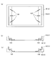
- FIG. 2A is a plan view
- FIG. 2B is a front view
- FIG. 2C is a cross-sectional view taken along line AA of FIG.
- FIG. 2A is a cross-sectional view taken along the line AA in FIG.
- FIG. 2A is a plan view of the transfer device of FIG. 2, in which the sub-transport conveyor unit and the regulating means connected thereto are indicated by solid lines, and the others are indicated by two-dot chain lines
- FIG. 2A is a cross-sectional view taken along the line AA in FIG. It is the perspective view which observed one short side wall part of the belt side frame of the main conveyance conveyor part from the back surface side.
- a control means The modification of a control means is shown, (a) is the perspective view, (b) is a sectional view in the state where the main conveyance conveyor part or the sub conveyance conveyor part is falling, (c) is the main It is sectional drawing of the state which the conveyance conveyor part or the sub conveyance conveyor part is rising, (d) is a cross-sectional view of a control means. It is explanatory drawing which modeled and demonstrated the relationship between a main conveyance conveyor part or a sub conveyance conveyor part, a main frame, and several linear control means, (a) is the top view, (b) is the main figure.
- FIG. 3 is a cross-sectional view conceptually illustrating a cross section AA in FIG. 2, and showing a positional relationship between a transport roller and a belt, and a geared motor.
- the transfer apparatus 1 according to the embodiment of the present invention will be described.
- the transfer device 1 according to the present embodiment has a large number of parts, and not only the shape of each part is complicated but also complicated. Therefore, in order to facilitate understanding of the invention, the outline and characteristic configuration of the transfer apparatus 1 will be described first, and then the specific configuration of each part will be described.
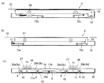
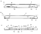
- the transfer device 1 includes a sub-transport conveyor unit (sub-transport unit) 2, a main transport conveyor unit (main transport unit) 3, and an elevating unit. And a geared motor 5. Moreover, in the transfer apparatus 1 of this embodiment, the control means 72 and 73 are provided so that the sub conveyance conveyor part 2 and the main conveyance conveyor part 3 may move straight up and down linearly.
- the sub-transport conveyor unit 2 of the transfer apparatus 1 includes a plurality of transport rollers 14 and a roller-side frame 19 that rotatably supports the transport rollers 14.
- cam followers 27 are respectively provided at four locations below the roller side frame 19.
- the cam follower 27 is a roller.
- the sub-transport conveyor unit 2 is a unit in which a plurality of transport rollers 14 and four cam followers 27 are integrated with the roller-side frame 19.
- At least one of the plurality of transport rollers 14 is a driving roller, and the other is a driven roller, and the driving roller and the driven roller are powered by a belt.
- the driving roller is a motor built-in roller, and a motor and a speed reducer are built in the roller body.
- the sub-transport conveyor section 2 has a transport path formed by a plurality of transport rollers 14, and the article 25 (FIG. 1) that is a transported object placed on the transport path is transported by the rotation of the transport roller 14. Is done.
- the drive motor for driving the roller is disposed in the same plane as each rotating body (roller). ing.
- the roller side frame 19 is restricted from moving in the horizontal direction by the restricting means 73a to 73d, and can reciprocate only in the vertical direction. Details of the restricting means 73a to 73d will be described later.
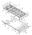
- the main transfer conveyor unit 3 includes one belt driving roller 80, a plurality of belt driven pulleys 81, annular belts 82 and 88 suspended from both rollers, and the belt side frame 18. And a belt conveyor body 85.
- the belt conveyor main body 85 includes three narrow first narrow belt conveyors 15 (stenosis conveyors) and one second narrow belt conveyor 30 (stenosis conveyor) as shown in FIGS. In addition, four rows are provided in parallel.
- the belt 82 of the first narrow belt conveyor 15 has an annular shape, and, as shown in FIG. 30, the traveling path of the belt 82 includes a conveyance path side 82a on which the article 25 (FIG. 1) is placed, and a lower side of the conveyance path side 82a. There is a return side 82b that passes through.
- the traveling path of the belt 88 of the annular second narrow belt conveyor 30 includes a conveyance path side 88a on which the article 25 (FIG. 1) is placed and a return side 88b that passes below the conveyance path side 88a.
- the conveyance path side 82a and the return side 82b of the first narrow belt conveyor 15 are parallel over almost the entire length in the conveyance direction of the article 25 by the main conveyance conveyor unit 3.
- the first narrow belt conveyor 15 has a substantially constant width in the height direction.
- a constricted portion 90 (FIG. 17) is provided near the center of the second narrow belt conveyor 30.
- the second narrow belt conveyor 30 has a substantially U-shape that is recessed downward by the constricted portion 90.
- the return side 88b of the belt 88 of the second narrow belt conveyor 30 approaches the conveyance path side 88a over a predetermined length in the conveyance direction of the article 25 by the main conveyance conveyor unit 3. Therefore, the width in the height direction of the second narrow belt conveyor 30 is narrower than the other portions in the constricted portion 90.
- a lower portion near the center of the second narrow belt conveyor 30 is recessed to form a constricted portion 90.
- the constricted portion 90 is in the vicinity of the center of the second narrow belt conveyor 30 and extends in the running direction of the belt 82.
- a space 78 (FIGS. 20 and 22C) is provided between the constricted portion 90 of the second narrow belt conveyor 30 and the bottom wall 31 of the main frame 12. , FIG. 30) is formed.
- the space 78 is a region defined by the constricted portion 90 and the bottom wall portion 31, and is located between the portion other than the constricted portion 90 of the second narrow belt conveyor 30 and the bottom wall portion 31, or the first narrow belt conveyor 15.
- the area in the height direction is wider than the space formed between the bottom wall portion 31 and the bottom wall portion 31.
- the space 78 is formed between the adjacent conveying rollers 14 of the sub-conveying conveyor unit 2 in the transfer apparatus 1, and the space 78 is formed in parallel with the conveying rollers 14. ing.
- each conveyance roller 14 does not pass through the space 78.
- the second narrow belt conveyor 30 and the first narrow belt conveyors 15 are arranged in parallel when viewed in plan.
- Each first narrow belt conveyor 15 is moved up and down by the elevating mechanism 4 at the side of the space 78, and the belt 82 of each first narrow belt conveyor 15 is driven by a belt driving roller 80 (travel path side 82 a, return). Travel along side 82b). Therefore, the belt 82 does not pass through the space 78.
- the belt 88 of the second narrow belt conveyor 30 travels on a traveling track (conveying path side 88a, return side 88b) along the constricted portion 90.
- the belt 88 passes through both ends in the longitudinal direction of the space 78 and above the space 78 so as to draw a U-shape, and travels while avoiding the space 78. Therefore, the belt 88 does not pass through the space 78.
- a geared motor 5 as an elevating means is arranged in this space 78.
- the attachment posture of the geared motor 5 is parallel to the conveyance rollers 14 of the sub-conveyance conveyor unit 2 and is disposed between the conveyance rollers 14.
- the position in the height direction of the geared motor 5 arranged in the space 78 is any one of the conveying bodies (conveying rollers) in a state where any of the conveying units (the main conveying conveyor unit 3 and the sub conveying conveyor unit 2) is lowered. 14, a position where a part or the whole of the geared motor 5 is higher than the height of the lower end of the rotation locus or the traveling locus of the belt 82, 88). Therefore, the height of the lower end of the lowered conveying roller 14, the height of the lower end of the belt 82 of the first narrow belt conveyor 15, and the height of the lower end of the belt 88 of the second narrow belt conveyor 30 are Lower than the highest part.
- the geared motor 5 is accommodated and disposed in the space 78 formed inside the transfer device 1, so that it does not collide with the main transport conveyor unit 3 and the sub transport conveyor unit 2 that move up and down.
- the geared motor 5 and the first narrow belt conveyor 15 of the main transfer conveyor unit 3 do not overlap in plan view. Therefore, the belt 82 of the first narrow belt conveyor 15 is moved up and down on the side of the geared motor 5 by the elevating mechanism 4, and the height position of the geared motor 5 increases the height of the lower end portion of the traveling locus of the belt 82. It is over.
- the height position of the geared motor 5 exceeds the height position of the lower end portion of the travel locus of the belt 88 (second narrow belt conveyor 30) of the main conveyor unit 3.
- the lower end portion of the travel locus of the belt 88 is a portion other than the constricted portion 90 on the return side 88b.
- the belt 88 suspended from the roller 67a, the second and third fixed tension pulleys 60b and 60c, and the roller 67b is along the U-shaped constricted portion 90 of the roller mounting member 59. That is, the belt 88 is disposed so as to avoid the geared motor 5 over the entire length of the geared motor 5 from the front end side (output shaft side) side portion of the geared motor 5 to the rear end side portion from above.
- the planar arrangement position of the geared motor 5 is a planar region overlapping the second narrow belt conveyor 30 (conveying unit) of the main transport conveyor unit 3, but the bottom wall of the second narrow belt conveyor 30 and the main frame 12.
- a space 78 is formed between the portions 31, and the geared motor 5 is disposed in the space 78.
- the space 78 is formed along the constricted portion 90 of the second narrow belt conveyor 30 as described above. Therefore, the height position of the geared motor 5 exceeds the height position of the lower end of the return side 88b of the belt 88 (conveyance body) passing through a portion other than the constricted portion 90 of the lowered second narrow belt conveyor 30. .
- the height position of the geared motor 5 is a position lower than the height of the constricted portion 90 of the lowered second narrow belt conveyor 30, and the height position of the lower end of the return side 88b of the belt 88 (conveyance body) is set. Not over. Therefore, the geared motor 5 and the belt 88 (conveyance body) do not interfere with each other even when the main conveyance conveyor section 3 (second narrow belt conveyor 30) is lowered.
- planar arrangement position of the geared motor 5 is a planar area overlapping the sub-conveying conveyor unit 2 (conveying unit), and the height position of the geared motor 5 is the conveying roller 14 ( The height of the lower edge of the (conveyor) is exceeded.
- FIG. 22C the lower end of the transport roller 14 is depicted by a two-dot chain line.
- the conveying roller 14 and the geared motor 5 are overlapped in the height direction.
- the geared motor 5 and each of the transport rollers 14 (transport body) do not interfere with each other because they have different installation positions when viewed in plan.
- the belt conveyor main body 85 of the main transport conveyor unit 3 an example in which three first narrow belt conveyors 15 and one second narrow belt conveyor 30 are provided in the belt conveyor main body 85 of the main transport conveyor unit 3 is shown.
- the second narrow belt conveyor 30 can be omitted. That is, by omitting the second narrow belt conveyor 30, a space for arranging the geared motor 5 of the lifting mechanism 4 in the transfer device 1 may be secured.
- the example which comprises the main conveyance conveyor part 3 with a belt conveyor was shown, you may comprise instead the roller conveyor which arranged the several roller in which articles
- the geared motor 5 of the lifting / lowering means can be disposed in the space 78 in the transfer device 1 without interfering with other members of the transfer device 1. Therefore, the overall height of the transfer device 1 can be reduced.
- geared motors can be used instead of the geared motor 5.
- a motor that can rotate at a low speed and is provided with a separate reduction gear can be used in place of the geared motor 5.
- the cam follower 36 is installed in each of the four locations on the lower outer side of the belt side frame 18.
- the cam follower 36 is a roller.
- the main transport conveyor unit 3 is a unit in which a belt driving roller 80, a plurality of belt driven pulleys 81, and four cam followers 36 are integrated with the belt side frame 18.
- the belt driving roller 80 is a roller with a built-in motor and includes a motor (not shown) having a speed reduction mechanism inside a rotatable outer cylinder. Therefore, the outer cylinder rotates when the motor is driven.
- the belt-side frame 18 is restricted from moving in the horizontal direction by the restricting means 72a to 72d, and can reciprocate only in the vertical direction. Details of the restricting means 72a to 72d will be described later.
- a conveyance path is formed by the belt 82, and the article 25 placed on the conveyance path is conveyed by running the annular belt 82.
- the transport path of the main transport conveyor unit 3 and the transport path of the sub transport conveyor unit 2 are arranged in the same plane area as shown in FIGS. 1, 2, 23, and 24. That is, the belt 82 of the main transport conveyor unit 3 is disposed between the transport rollers 14 of the sub transport conveyor unit 2, and the two transport paths are in the same plane area.
- the raising / lowering means is comprised by the raising / lowering mechanism 4 and the geared motor 5 which combined several members.
- the elevating mechanism 4 includes a gear train 52, a power transmission shaft 39, a pinion gear 26, a horizontal movement member 11, a cam follower 27 belonging to the sub-conveying conveyor unit 2, and a cam follower belonging to the main conveying conveyor unit 3. 36 or the like.
- the power transmission shaft 39 is disposed in a direction intersecting the output shaft of the geared motor 5.
- the power transmission shaft 39 is in a twisted position with respect to the output shaft of the geared motor 5. That is, the height of the power transmission shaft 39 is lower than the output shaft (not shown) of the geared motor 5. Both ends of the power transmission shaft 39 reach the vicinity of both ends of the transfer device 1, and pinion gears 26 are attached to both ends.
- the torsional position means a positional relationship between two straight lines that are not parallel and do not intersect.
- the power transmission shaft 39 is disposed in the transfer apparatus 1 so as to be slightly separated below the respective transport rollers 14 of the main transport conveyor unit 3 and the belts 82 and 88 of the sub transport conveyor unit 2. It is orthogonal to the conveying roller 14 and the belts 82 and 88.
- the gear train 52 connects the output shaft of the geared motor 5 in a twisted position as shown in FIG. 5 and an intermediate portion of the power transmission shaft 39, and the rotational force of the geared motor 5 is applied to the power transmission shaft 39. It is a transmission. Therefore, when the geared motor 5 rotates, the pinion gears 26 attached to both ends of the power transmission shaft 39 rotate.
- two horizontal moving members 11 are arranged in parallel between the roller side frame 19 and the belt side frame 18.
- the horizontal moving member 11 is provided with a rack portion 9 facing downward.
- the horizontal movement member 11 can reciprocate only in the longitudinal direction.
- the pinion gear 26 described above engages with the rack portion 9 formed downward.
- the power transmission shaft 39 is twisted with respect to the output shaft of the geared motor 5 and is disposed below the output shaft (not shown) of the geared motor 5.
- the pinion gear 26 provided on the power transmission shaft 39 is engaged with the rack portion 9 formed downward.
- the horizontal movement member 11 is a linear motion cam and includes a long upper surface 11 b.
- the rack portion 9 described above is provided in the center of the upper surface 11b and on the lower surface side.
- the rack part 9 is engaged with the pinion gear 26 described above.
- the horizontal movement member 11 reciprocates in the horizontal direction. That is, by rotating the geared motor 5 described above, power is transmitted to the horizontal moving member 11 and the horizontal moving member 11 reciprocates.
- the horizontal moving member 11 is a linear cam as described above, and cam recesses 28 and 29 are provided on the upper surface 11b. That is, the cam recesses 28 and 29 are provided on both sides of the rack portion 9, respectively.
- the cam recesses 28 and 29 are fitted with the cam follower 27 provided on the roller side frame 19 and the cam follower 36 provided on the belt side frame 18. That is, when the geared motor 5 rotates and the pinion gear 26 rotates, the upper surface 11b of the horizontal moving member 11 moves horizontally while rotating the cam follower 27, and when the cam recesses 28 and 29 reach the position of the cam follower 27, FIG.
- the cam follower 27 is dropped into the cam recesses 28 and 29 as shown in FIG.
- the roller side frame 19 integrated with the cam follower 27 is lowered, and the sub-transport conveyor unit 2 is lowered downward.
- the main transfer conveyor unit 3 remains in the raised position.
- the main transport conveyor unit 3 and the sub transport conveyor unit 2 are both unitized and arranged in the main frame 12.
- the main transfer conveyor unit 3 and the main frame 12 are coupled only by the four restricting means 72a to 72d.
- the sub-transport conveyor unit 2 and the main frame 12 are also coupled by only four restricting means 73a to 73d.
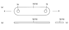
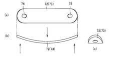
- the restricting means 72 and 73 employed in the transfer device 1 of the present embodiment are leaf springs. That is, the regulating means 72 and 73 are made by punching a thin plate-shaped spring steel, and the planar shape is an oval shape as shown in FIG. That is, the regulating means 72 and 73 are oval thin plates, have elasticity, and bend in a certain direction.
- the restricting means 72 and 73 are easily bent in the direction perpendicular to the plane as shown in FIGS. That is, when a bending force is applied in a direction perpendicular to the plane as shown by arrows in FIGS. However, as shown by the arrows in FIG. 9, it exerts a strong resistance against the force in the twisting direction and is difficult to twist.
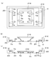
- FIG. 13 is an explanatory diagram modeling and explaining the relationship between the main transport conveyor unit 3 or the sub transport conveyor unit 2, the main frame 12, and the four regulating means 72 and 73.
- a rectangular frame A is a model of the main transport conveyor unit 3 or the sub transport conveyor unit 2.
- Surface B is a model of the main frame 12.
- the frame A (the main transport conveyor unit 3 or the sub transport conveyor unit 2) and the surface B are joined by four regulation means 72 and 73. That is, one end side of the regulating means 72 and 73 is joined to the frame A (the main transport conveyor unit 3 or the sub transport conveyor unit 2), and the other end side of the regulating means 72 and 73 is joined to the surface B (the main frame 12).
- the restricting means 72 and 73 are plate bodies and can be fixed simply by screwing them to the frame A and the surface B. Therefore, the assembly of the transfer device 1 is easy.
- the planar positional relationship between the restricting means 72 and 73 is as shown in FIG. 13A, and the frame A-side joining portion 200 of the restricting means 72 and 73 is joined to the frame A, and the restricting means 72 and 73.
- the surface B-side joint portion 201 is in a plane area surrounded by the frame A.
- the regulating means 72 and 73 are arranged in a plane posture, and the plane of the regulating means 72 and 73, the virtual plane of the frame A, and the plane formed by the plane B are substantially parallel. That is, the lower surfaces of the regulating means 72 and 73 are opposed to the plane formed by the main frame 12 as the surface B, and the upper surfaces of the regulating means 72 and 73 are opposed to the virtual plane of the frame A. That is, the restricting means 72 and 73 are elastic plates that are bent in a certain direction, and the restricting means 72 and 73 are moved up and down by the frame A (the main transfer conveyor unit 3 or the auxiliary transfer conveyor unit 2). It is attached between the surface B (main frame 12) and the frame A in a posture matched to the moving direction.
- the restricting means 72 and 73 are leaf springs and are easily bent in a direction perpendicular to the plane, but are not easily twisted.
- the planes of the regulating means 72 and 73 are substantially parallel to the plane formed by the virtual plane of the frame A and the plane B. Therefore, when the individual restricting means 72 and 73 are observed, the frame A side joint portion 200 of the restricting means 72 and 73 can be moved straight in the direction perpendicular to the surface B by bending. That is, when the frame A is lifted by the cam, the restricting means 72 and 73 bend and warp in an upper chord state, and move the frame A vertically without shaking.
- each restricting means 72, 73 are attached between the frame A and the surface B, so that each frame A-side joint 200 of each restricting means 72, 73. Move straight in the direction perpendicular to the plane B.
- four regulating means 72 and 73 are attached between the frame A and the surface B, respectively, and the frame A side joint portion 200 of the regulating means 72 and 73 is a part close to the corner of the frame A.
- the restricting means 72 and 73 have a property of being difficult to twist, a large force is not required for the frame A and the surface B to approach and separate in parallel. When the frame A and the surface B are inclined or twisted, the reaction force of the restricting means 72 and 73 tries to correct them to a parallel posture.
- the restriction means 72 and 73 restrict the frame A so as to move up and down straight with respect to the surface B.
- the main transport conveyor unit 3 and the main frame 12 are coupled by only four regulating means 72, and the main transport conveyor unit 3 is connected to the main by the action of the four regulating means 72. It is restricted to move in a direction perpendicular to the frame 12. More specifically, the belt-side frame 18 of the main conveyor unit 3 is restricted from moving in the horizontal direction by the restricting means 72 and can reciprocate only in the vertical direction.
- the sub-conveying conveyor unit 2 is operated by the four restricting means 73. Therefore, the main frame 12 is restricted so as to move in a vertical direction. That is, the roller-side frame 19 of the sub-conveying conveyor unit 2 is restricted from moving in the horizontal direction by the restricting means 73 and can reciprocate only in the vertical direction.
- the main transport conveyor unit 3 and the sub transport conveyor unit 2 each have four cam followers 36 and 27, and the four cam followers 36 and 27 are moved by the horizontal moving member 11 that is a linear motion cam. Are raised and lowered at the same time. For this reason, the four cam followers 36 of the main transport conveyor unit 3 are lifted and lowered simultaneously by the horizontal moving member 11, so that the main transport conveyor unit 3 moves up and down while maintaining a horizontal posture. The same applies to the sub-conveying conveyor unit 2, and the four cam followers 27 of the sub-conveying conveyor unit 2 are simultaneously moved up and down by the horizontal moving member 11, so that the sub-conveying conveyor unit 2 moves up and down while maintaining a horizontal posture.
- the regulating means 72 and 73 are leaf springs that are extremely thin and are arranged in parallel to the virtual plane of the main transport conveyor unit 3 and the virtual plane of the sub transport conveyor unit 2.
- the restricting means 72 and 73 have a planar posture and the total height is extremely low. That is, the height of the restricting means 72 and 73 is merely the thickness of the leaf spring, and is significantly lower than that of the prior art guide. Therefore, the total height of the transfer apparatus 1 of this embodiment is low.
- the main transport conveyor unit 3 or the sub transport conveyor unit 2 is modeled and the frame A is illustrated, and the main frame 12 is modeled and the surface B is illustrated. It was.
- the belt side frame 18 which is a part of the main transport conveyor unit 3 is smaller than the roller side frame 19 which is a part of the sub transport conveyor unit 2 as shown in FIG.
- the frame 18 is housed in the roller side frame 19. Therefore, both are in a common area in the height direction.
- four regulating means 72a to 72d shown in FIG. 15 are attached between the belt side frame 18 and the main frame 12, and guide the belt side frame 18 in the vertical direction.
- four regulating means 73a to 73d shown in FIG. 21 are attached between the roller side frame 19 and the main frame 12 to guide the roller side frame 19 in the vertical direction.
- the transfer apparatus 1 of this embodiment is arrange
- the transfer device 1 is arranged between the upstream main conveyance line 22 and the downstream main conveyance line 23 arranged in a straight line to form the main line 100, and is orthogonal to the main conveyance lines 22 and 23.
- the auxiliary transport line 24 is connected to the transfer device 1.
- the conveyor line 21 conveys the article 25 along the main line 100 (main conveyance lines 22 and 23) or changes the conveyance direction on the transfer device 1, and transfers the article 25 to the sub line 101 (sub conveyance line 24). ).
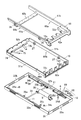
- the transfer apparatus 1 includes a main frame 12 that accommodates and arranges all the constituent members, and a main transport conveyor unit 3 that transports an article 25 (FIG. 1) to the main transport line 23 (FIG. 1). And the sub-transport conveyor unit 2 that transports the article 25 to the sub-line 101.
- the transfer device 1 has an elevating mechanism 4.
- the main frame 12 has a bottom wall portion 31, long side wall portions 32a and 32b, and short side wall portions 33a and 33b.
- the bottom wall portion 31 has a rectangular thin plate shape.
- Long side wall portions 32 a and 32 b are provided on the long side edge of the bottom wall portion 31.
- Short side wall portions 33 a and 33 b are provided on the short side edge of the bottom wall portion 31.
- the long side wall portions 32a and 32b and the short side wall portions 33a and 33b are connected to each other to form a frame that surrounds the four sides.
- the long side wall portions 32 a and 32 b and the short side wall portions 33 a and 33 b are fixed orthogonally to the bottom wall portion 31.
- the bottom wall portion 31 is provided with four guide members 68 along the long side wall portions 32a and 32b from the end side to the center side of the long side wall portions 32a and 32b.
- the guide member 68 includes a floor plate 68a, a guide rail 68b, and a screw 68c.
- the floor plate 68a is a substantially rectangular thin plate member.
- the guide rail 68b is a plate-like member having the same length as the floor board 68a and a width smaller than the floor board 68a.
- a guide rail 68b is disposed at the center of the floor plate 68a, and both ends of the both are penetrated by screws 68c and fixed to the bottom wall portion 31.
- the rail part 69 is comprised on the flooring board 68a of the both sides of the guide rail 68b.
- the bottom wall portion 31 is provided with four cylindrical fixing portions 34a to 34d and four cylindrical fixing portions 35a to 35d. A female screw is formed inside each cylindrical fixing portion. Of these eight cylindrical fixing portions, only the cylindrical fixing portions 35c and 35d are longer than the other cylindrical fixing portions.
- One ends of restricting means 73a to 73d are fixed to the four cylindrical fixing portions 34a to 34d of the main frame 12. The other ends of the restricting means 73a to 73d are coupled to the roller-side frame 19 of the sub-transport conveyor unit 2. Further, one end of the restricting means 72a to 72d is fixed to the four cylindrical fixing portions 35a to 35d of the main frame 12. The other ends of the regulating means 72a to 72d are coupled to the belt side frame 18 of the main transport conveyor unit 3. That is, each of the cylindrical fixing portions 34a to 34d and 35a to 35d is connected to a belt side frame 18 and a roller side frame 19 which will be described later via regulating means 72a to 72d and 73a to 73d as shown in FIG.
- An elevating mechanism 4 is provided on the bottom wall portion 31. As shown in FIG. 5, the lifting mechanism 4 includes a geared motor 5, a power transmission shaft 39, a horizontal movement member 11, and the like.
- a helical gear (not shown) is mounted on the output shaft (not shown) of the geared motor 5.
- the geared motor 5 is fixed to the central portion of the bottom wall portion 31 by fixing members 37 a and 37 b with an output shaft (not shown) facing the longitudinal direction of the main frame 12.
- a gear box 38 is fixed to the fixing member 37b.
- An output shaft (not shown) of the geared motor 5 is accommodated in the gear box 38.
- the power transmission shaft 39 has a length slightly shorter than the length of the bottom wall portion 31 in the short direction.
- a helical gear (not shown) different from the helical gear (not shown) provided in the geared motor 5 is provided in the middle of the power transmission shaft 39.
- pinion gears 26 a and 26 b are provided at both ends of the power transmission shaft 39.
- the power transmission shaft 39 extends in the short direction of the main frame 12 and is arranged at the center of the bottom wall portion 31. Near both ends of the power transmission shaft 39 are supported by bearing members 40a and 40b.
- the pinion gear 26a is disposed between the two guide members 68 along the long side wall portion 32a.
- the pinion gear 26b is disposed between the two guide members 68 along the long side wall portion 32b.
- the power transmission shaft 39 passes through the gear box 38 from a direction orthogonal to the output shaft (not shown) of the geared motor 5.
- a helical gear (not shown) of the power transmission shaft 39 is accommodated in the gear box 38.
- a helical gear (not shown) on the geared motor 5 side and a helical gear (not shown) on the power transmission shaft 39 side are directly or indirectly engaged so that power transmission is possible.
- the power transmission shaft 39 is below the output shaft (not shown) of the geared motor 5.
- the power transmission shaft 39 and the output shaft (not shown) of the geared motor 5 are in a torsional positional relationship.
- the horizontal moving member 11 is a long and substantially rectangular parallelepiped member as shown in FIGS. 3, 5, and 6.
- the horizontal movement member 11 has a substantially rectangular cross section, and the horizontal movement member 11 is disposed in the main frame 12 in such a posture that the longitudinal direction of the rectangle of the cross section coincides with the vertical direction.
- a recess is formed in the central portion of the lower surface 11 a of the horizontal moving member 11.
- a rack portion 9 is provided in this recess.
- Rack teeth 9a are formed on the rack portion 9 by appropriate means such as gear cutting. That is, the rack teeth 9a of the rack portion 9 are formed downward.
- the four shafts 10 are provided on the side surface of the horizontal moving member 11 so as to pass through four places in the longitudinal direction of the horizontal moving member 11.
- Two shafts 10 are arranged on both sides of the rack portion 9.
- a pair of induction rollers 6 is attached to each shaft 10.
- the upper surface 11b of the horizontal moving member 11 has a plurality of portions having different heights as shown in FIG. 6, FIG. 7, and FIG. That is, on the upper surface 11b of the horizontal moving member 11, in order from one end, the first low position portion 8a (cam recessed portion 28a), the first high position portion 7a, the second low position portion 8b (cam recessed portion 28b), the first A second high position portion 7b, a third low position portion 8c (cam concave portion 29a), a third high position portion 7c, and a fourth low position portion 8d (cam concave portion 29b) are formed.
- the first low position portion 8 a and the fourth low position portion 8 d are formed at both ends of the horizontal movement member 11.
- the second high position portion 7b is formed at the central portion in the longitudinal direction of the horizontal moving member 11, and constitutes the highest portion of the upper surface 11b. That is, the second high position portion 7b is formed on the upper surface 11b of the central portion in the longitudinal direction of the horizontal moving member 11, and the rack portion 9 is formed on the lower surface 11a below the second high position portion 7b. .
- the guide roller 6 is disposed on the rail portion 69 of the floor plate 68 a of the guide member 68. That is, the pair of guide rollers 6 are arranged on both sides of the guide rail 68b and can reciprocate along the guide rail 68b.
- FIG. 6C shows a state in which the pinion gear 26 a (26 b) is engaged with the central portion of the rack portion 9 of the horizontal moving member 11.
- the pinion gear 26a rotates counterclockwise as viewed in FIG. 6C
- the horizontal movement member 11 moves to the left as shown in FIG. 8C.
- the pinion gear 26a rotates clockwise as viewed in FIG. 6C
- the horizontal movement member 11 moves to the right as shown in FIG. 7C.
- the main conveyor unit 3 includes a belt-side frame 18 and a belt conveyor body 85.
- the belt conveyor main body 85 is formed by four rows of three narrow first narrow belt conveyors 15 (stenosis conveyor) and one second narrow belt conveyor 30 (stenosis conveyor) in parallel.
- the driving pulley of the four rows of narrow belt conveyors is shared by one belt driving roller 80. That is, in this embodiment, one belt drive roller 80 (motor built-in roller) is used as a common drive pulley.
- the first narrow belt conveyor 15 has a structure as shown in FIG. 16, and a plate-like roller mounting member 16 is provided on one side, and the belt mounting member 16 includes one belt driven pulley 81 and two belt driven pulleys 81. A fixed tension pulley 83 and a plurality of rollers 17 are provided.
- a narrow belt 82 is suspended between a common driving pulley (belt driving roller 80) and each driven pulley.
- Each roller 17 is disposed inside the annular belt 82 so as to support the load applied to the belt 82. That is, the belt driving roller 80 is arranged in the horizontal direction in the same row as the belt driven pulley 81 fixed to the roller mounting member 16 and the plurality of rollers 17. Therefore, the overall height of the main transport conveyor unit 3 is low.
- the fixed tension pulley 83 presses the belt 82 from the outside.
- the roller mounting member 16 has a structure in which an elongated plate-like member is bent in an L shape along the longitudinal direction.
- an auto tensioner 87 is attached to the belt 82. As shown in FIG. 16, the auto tensioner 87 is attached to the roller mounting member 16.
- the auto tensioner 87 includes a swing piece 94, a movable tension pulley 84, and a spring 86.
- the roller mounting member 16 is provided with a long hole-shaped spring accommodating hole and a spring fixing hole.
- the spring fixing hole is provided at one end in the longitudinal direction of the spring accommodation hole.
- One end of a spring 86 is fixed to the spring fixing hole of the roller mounting member 16. A part of the spring 86 is accommodated in the spring accommodating hole.
- the rocking piece 94 is fixed to the roller mounting member 16 via a shaft so as to be rotatable.
- a movable tension pulley 84 is provided at the tip of the swing piece 94.
- the movable tension pulley 84 can freely rotate with respect to the swing piece 94.
- the other end of the spring 86 is fixed to the rear end portion of the swing piece 94.
- the spring 86 connects the spring fixing hole 92b of the roller mounting member 16 and the rear end portion of the swing piece 94, and a part of the spring 86 is disposed in the spring accommodating hole 92a.
- the spring 86 is a tension spring and pulls the swing piece 94.
- the swing piece 94 rotates (swings), the movable tension pulley 84 fixed to the tip of the swing piece 94 presses the belt 82, and an appropriate tension is applied to the belt 82.
- the auto tensioner 87 has a movable tension pulley 84, and the movable tension pulley 84 can freely rotate, and can move toward and away from the belt 82.
- short side wall portion 42b and the roller mounting member 16 are bolted.
- short side wall portion 42a and the roller attachment member 16 are bolted.
- the second narrow belt conveyor 30 has a structure as shown in FIGS. 17 to 19, and a plate-like roller mounting member 59 is provided on one side, and one belt driven pulley 81 and one roller mounting member 59 are provided on the roller mounting member 59.
- Three fixed tension pulleys 60 first fixed tension pulley 60a, second fixed tension pulley 60b, and third fixed tension pulley 60c), a plurality of rollers 67 (67a to 67c), and a plurality of small diameter rollers 89 are provided. ing.
- a belt driven pulley 81, three fixed tension pulleys 60, a plurality of rollers 67, and a plurality of small diameter rollers 89 are rotatably mounted on the roller mounting member 59.
- three fixed tension pulleys 60 (60a to 60c), a plurality of rollers 67 (67a to 67c), and a plurality of small diameter rollers 89 are provided.
- a narrow and narrow belt 88 is suspended.
- the rollers 67a to 67c and the plurality of small-diameter rollers 89 are disposed inside the belt 88 so as to support the load applied to the belt 88.
- Each of the fixed tension pulleys 60a to 60c applies tension to the belt 88 by pressing the belt 88 from the outside.
- the roller attachment member 59 is provided with a constricted portion 90 having a small size in the height direction.
- the constricted portion 90 is provided near the lower center of the second narrow belt conveyor 30.
- the second narrow belt conveyor 30 has a U-shape.
- a plurality of small diameter rollers 89 are arranged along the constricted portion 90.
- the annular belt 88 passes through an upper conveyance path side 88a and a lower return side 88b, which are travel loci.
- the article 25 (FIG. 1) is placed on the belt 88 passing through the conveyance path side 88a, and a load is applied.
- Each roller 67 (67a to 67c) and each small-diameter roller 89 support the load of the article 25.
- each member of the second narrow belt conveyor 30 is as follows. That is, the belt driving roller 80 and the belt driven pulley 81 are arranged on both sides, and in the belt 88, a roller 67a, a plurality of small-diameter rollers 89, and rollers 67b and 67c are arranged in this order from the belt driving roller 80 side. Yes. A first fixed tension pulley 60a that presses the belt 88 from the outside is disposed between the belt driving roller 80 and the roller 67a.
- a second fixed tension pulley 60b is disposed between the roller 67a and the small diameter roller 89
- a third fixed tension pulley 60c is disposed between the small diameter roller 89 and the roller 67b. That is, the second and third fixed tension pulleys 60 b and 60 c are arranged on both sides of the plurality of small diameter rollers 89.
- the belt 88 is lifted along the constricted portion 90 of the roller mounting member 59, and the belt 88 A part of the return side 88b (lower side) of the traveling locus of this is approaching the conveyance path side 88a (upper side).
- a portion of the belt 88 where the conveyance path side 88a and the return side 88b are close to each other is protected by the upper cover 50a and the lower cover 50b.
- a space 78 is formed below the upper cover 50a and the lower cover 50b.
- an auto tensioner 87 is attached to the second narrow belt conveyor 30.
- the auto tensioner 87 has the same structure as the auto tensioner 87 of the first narrow belt conveyor 15, and a duplicate description is omitted.
- the second narrow belt conveyor 30 is bolted to the belt side frame 18 in the same manner as the first narrow belt conveyor 15.
- the belt side frame 18 is a frame-like member composed of two long side wall portions 41a and 41b and two short side wall portions 42a and 42b as shown in FIGS.
- the long side wall portions 41a and 41b have the same structure, but the left and right sides are different.
- the long side wall 41a will be mainly described, and redundant description on the long side wall 41b will be omitted.
- the long side wall portion 41a is a long flat plate-like member, and the upper side is bent at a right angle to form a flange shape.
- a projecting portion 48a projecting downward is provided at one end of the long side wall portion 41a.
- a protrusion 48b protruding downward is provided in the vicinity of the end opposite to the end where the protrusion 48a of the long side wall 41a is provided.
- the protrusions 48a and 48b protrude to the same extent.
- a roller fixing hole 43 is provided in the vicinity of the end of the long side wall portion 41a on the protruding portion 48a side.
- follower fixing holes 44a are provided at two locations on the long side wall 41a.
- the follower fixing hole 44a is a hole for rotatably supporting the cam follower 36.
- Two cam followers 36 are arranged at a predetermined interval in the longitudinal direction of the long side wall 41a, and both the cam followers 36 are provided outside the long side wall 41a.
- One cam follower 36 is provided at a portion from which the protruding portion 48b protrudes.
- the short side wall portions 42a and 42b are flat plate-like members shorter than the long side wall portions 41a as shown in FIGS.
- Each part of the short side wall part 42a is appropriately bent as shown in FIGS. 15 and 25, and has a lower horizontal part 45a, a vertical part 45b, and an upper horizontal part 45c.
- the lower horizontal portion 45a and the upper horizontal portion 45c are arranged on opposite sides of the vertical portion 45b.
- the upper horizontal portion 45c is provided with four projecting portions 46a to 46d. Each of the protruding portions 46a to 46d protrudes to the opposite side of the vertical portion 45b in the same plane as the upper horizontal portion 45c.
- the protrusions 46a to 46d are arranged at predetermined equal intervals in order from the end of the upper horizontal portion 45c.
- a hole 47 is provided in the vicinity of the free end of each of the protrusions 46a to 46d.
- cylindrical fixing portions 70c and 70d are provided on the lower surface side of the protruding portions 46a and 46d.
- the cylindrical fixing portions 70 c and 70 d are fixed to the protruding portions 46 a and 46 d by screws that pass through the holes 47.
- Female screws are formed inside the cylindrical fixing portions 70c and 70d.
- One ends of restricting means 72c and 72d are fixed to the cylindrical fixing portions 70c and 70d.
- Both ends of the short side wall portion 42a are connected to the tips of the protruding portions 48a of the long side wall portions 41a and 41b, respectively.
- the projecting portions 46a to 46d of the short side wall portion 42a are arranged so as to face the center side of the long side wall portions 41a and 41b, and the lower horizontal portion 45a is formed of the long side wall portions 41a and 41b. It is arrange
- the short side wall portion 42b is an elongated plate member having the same length as the short side wall portion 42a.
- the first narrow belt conveyor 15 and the second narrow belt conveyor 30 are bolted along the long side of the short side wall portion 42b.
- the long side wall portions 41a and 41b and the short side wall portions 42a and 42b constitute a frame-like belt side frame 18. Both end portions of the short side wall portion 42a (lower horizontal portion 45a) are fixed to the protruding portions 48a of the long side wall portions 41a and 41b, and both end portions of the short side wall portion 42b are on the long side side. It is being fixed to the front-end
- the sub-transport conveyor unit 2 includes a roller side frame 19 and a roller conveyor body 13 as shown in FIG.
- the roller conveyor body 13 is disposed on the roller side frame 19.
- at least one of the plurality of transport rollers 14 is a driving roller, and the other is a driven roller, and the roller conveyor body 13 is driven by a belt.
- the roller side frame 19 has two long side wall portions 51a and 51b and two short side wall portions 52a and 52b.
- the long side wall portions 51a and 51b have the same structure, but the left and right sides are different.
- the long side wall 51a will be mainly described, and redundant description on the long side wall 51b will be omitted.
- the roller side frame 19 is a frame-like member composed of long side wall portions 51a and 51b and short side wall portions 52a and 52b as shown in FIGS.
- the roller side frame 19 is slightly larger than the belt side frame 18 and can accommodate the belt side frame 18 therein.
- the long side wall 51a is composed of a long flat plate member.
- the upper side of the long side wall 51a is bent at a right angle to form a flange shape.
- follower fixing holes 54a are provided at two locations on the long side wall 51a.
- the follower fixing hole 54a is a hole for rotatably supporting the cam follower 27 (depicted on the long side wall 51b).
- the two cam followers 27 are arranged at a predetermined interval in the longitudinal direction of the long side wall portion 51a, and both the cam followers 27 are provided at a portion off the center of the long side wall portion 51a.
- the short side wall portions 52a and 52b are flat members that are shorter than the long side wall portions 51a.
- the short side wall portion 52a has a structure in which a flat plate is bent into a substantially U shape. That is, as shown in FIG. 26, the short side wall portion 52a has a bottom wall portion 55a and vertical wall portions 55b and 55c, and the vertical wall portions 55b and 55c stand up from both sides of the bottom wall portion 55a. .
- the vertical wall 55c has a higher standing height from the bottom wall 55a than the vertical wall 55b.
- fixing holes 76a and 76b are provided in the vicinity of both ends in the longitudinal direction of the bottom wall portion 55a.
- Projecting portions 56a to 56e projecting upward are provided on the upper edge portion of the vertical wall portion 55c.
- the protrusions 56a to 56e are arranged at a predetermined interval of equal intervals.
- the second projecting portion 56b from the end has a longer projecting length than the other projecting portions, and is bent at a right angle in a direction away from the bottom wall portion 55a to form a horizontal portion 53. It is bent to face.
- the protrusions 56a to 56e have the same height. Holes 57 are provided in the vicinity of the tips of the protrusions 56a to 56e.
- Vertical wall portions 58 are provided at both ends in the longitudinal direction of the short side wall portion 52a.
- the vertical wall portion 58 is lower than the projecting portions 56a to 56e.
- the short side wall portion 52b is composed of a plate-like member having a length comparable to that of the short side wall portion 52a.
- the short side wall portion 52b is bent along the longitudinal direction to form a bottom wall portion 61a and a vertical wall portion 61b.
- the bottom wall portion 61a is provided with two fixing holes 62a and 62b at a predetermined interval.
- Notches 65a to 65e are provided at equal intervals on the upper side of the vertical wall 61b. Projections 63a to 63d projecting upward are formed on the upper side of the vertical wall 61b by the notches 65a to 65e.
- connection wall part 64 which continues the vertical wall part 61b is provided in the both ends of the short side wall part 52b.
- the connection wall part 64 has orthogonal side wall parts 64a and 64b.
- the side wall part 64a is connected orthogonally to the vertical wall part 61b.
- the width of the bottom wall portion 61a and the width of the side wall portion 64a are the same, and the side wall portion 64a is bent in the same direction as the bottom wall portion 61a with respect to the vertical wall portion 61b.
- the side wall portion 64b is orthogonal to the side wall portion 64a and extends to the side where the bottom wall portion 61a is not present.
- the roller-side frame 19 is a frame-like member in which the long side wall portions 51a and 51b are opposed to each other, one end is connected by the short side wall portion 52a, and the other end is connected by the short side wall portion 52b. It is. Lower portions of one ends of the long side wall portions 51a and 51b are connected to the vertical wall portions 58 on both sides of the short side wall portion 52a.
- the other ends of the long side wall portions 51a and 51b are connected to the side wall portions 64b of the connection wall portions 64 on both sides of the short side wall portion 52b. Therefore, a space 66b is formed below the connection wall portion 64 and the long side wall portions 51a and 51b.
- the cam follower 27 is rotatably fixed to the long side wall portions 51a and 51b while floating in the air above the space 66b. Further, the cam follower 27 is disposed inside the frame of the roller side frame 19.
- the main frame 12 and the belt side frame 18 are connected by four restricting means 72a to 72d (plate springs).
- the restricting means 72a to 72d are thin and thin plate-like members as described above, and are members having both rigidity and elasticity. As shown in FIG. 9, holes 74 and 75 are provided near both ends of the restricting means 72a to 72d.
- the restricting means 73a to 73d are members having the same configuration as the restricting means 72a to 72d. Holes 74 and 75 are provided near both ends of the regulating means 73a to 73d.
- the short side wall portion 52a of the roller side frame 19 is connected to the main frame 12 by restricting means 73c and 73d. Specifically, the fixing hole 76a of the short side wall portion 52a and the hole 74 of the restricting means 73c are coincident with each other and are fixed with bolts and nuts. Further, as shown in FIG.
- the cylindrical fixing portion 34c of the main frame 12 and the hole 75 of the restricting means 73c coincide with each other and are fixed with bolts and nuts.
- the restricting means 73 c is fixed to the fixing hole 76 a of the short side wall portion 52 a and the cylindrical fixing portion 34 c of the main frame 12.
- the restricting means 73d is fixed to the fixing hole 76b of the short side wall portion 52a and the cylindrical fixing portion 34d of the main frame 12.
- the short side wall portion 52b of the roller side frame 19 is connected to the main frame 12 by regulating means 73a and 73b shown in FIG. That is, the restricting means 73a and 73b are fixed to the fixing holes 62a and 62b of the short side wall portion 52b and the cylindrical fixing portions 34a and 34b (FIG. 4) of the main frame 12, respectively.
- the transfer device 1 in a state where the above-described members are assembled has a planar shape as shown in FIG. 22A and a front shape as shown in FIG.
- the positional relationship between the restricting means 72 and 73 is as shown in FIGS. That is, since the eight restricting means 72 and 73 are arranged at positions separated from each other as shown in FIGS. 23 (a) and 24 (a), the other restricting means 72, 73 when bent. 73, the main conveyance conveyor part 3 and the sub conveyance conveyor part 2 can be raised / lowered smoothly.
- the eight regulating means 72 and 73 are in the same region in the height direction as shown in FIGS. 23B and 24B, and are transferred because the individual heights are low. The overall height of the device 1 is low.
- the transfer device 1 When the conveyance direction of the article 25 shown in FIG. 1 is set, the transfer device 1 is operated as follows. When the article 25 is transported from the upstream main transport line 22 to the downstream main transport line 23, the main transport conveyor unit 3 of the transfer device 1 is raised, and the belts 82 and 88 are disposed on the transport path. The sub-conveying conveyor unit 2 is lowered and the conveying roller 14 is retracted below the conveying path. That is, the geared motor 5 is driven to move the horizontal moving member 11 to the right as shown in FIG. 7C, and the cam follower 36 of the main transfer conveyor unit 3 is moved to the first high position portion 7a and the third high position.
- the cam followers 27 of the sub-transport conveyor unit 2 are arranged on the first low position portion 8a (cam concave portion 28a) and the third low position portion 8c (cam concave portion 29a).
- the main transport conveyor unit 3 moves to the raised position
- the sub-transport conveyor unit 2 moves to the lowered position.
- Belts 82 and 88 are arranged on the conveying surface, and the article 25 is conveyed to the downstream main conveying line 23 side by the main conveying conveyor unit 3 of the transfer device 1.
- the regulating means 72 and 73 guide the main transport conveyor unit 3 and the sub transport conveyor unit 2 to move in the vertical direction.
- the sub transport conveyor unit 2 of the transfer device 1 is raised, and the transport rollers 14 are arranged on the transport path.
- the conveying conveyor unit 3 is lowered and the belts 82 and 88 are retracted downward in the conveying path. That is, the geared motor 5 is driven to move the horizontal moving member 11 to the left as shown in FIG. 8C, and the cam follower 36 of the main transfer conveyor unit 3 is moved to the second low position portion 8b (cam recessed portion 28a).
- the cam follower 27 of the sub-transport conveyor unit 2 is disposed on the first high position portion 7a and the third high position portion 7c, as well as on the fourth low position portion 8d (cam recess 29b).
- the main transfer conveyor unit 3 moves to the lowered position, and the auxiliary transfer conveyor unit 2 moves to the raised position.
- a conveyance roller 14 is disposed on the conveyance surface, and the article 25 is conveyed to the sub conveyance line 24 side by the sub conveyance conveyor unit 2 of the transfer device 1.
- the restricting means 72 and 73 guide the main transport conveyor unit 3 and the sub transport conveyor unit 2 to move in the vertical direction.
- leaf springs are employed as the restricting means 72 and 73.
- the sub-transport conveyor unit 2 and the main transport conveyor unit 3 are guided so as to move up and down in a straight line by utilizing the elasticity of the leaf springs.
- the present invention is not limited to this configuration, and a plate body that can be inclined can be employed instead of the plate spring.
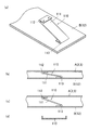
- FIG. 27 shows an example in which a tiltable plate body 111 is employed as the regulating means 110.
- the main body of the restricting means 110 is a plate body 111 that has a small elastic force and is not easily bent.
- both ends of the regulating means 110 are connected to the frame A (the main transport conveyor unit 3 or the sub transport conveyor unit 2) and the surface B (the main frame 12) via hinges 112 and 113, as shown in FIG. It can take a posture close to horizontal as shown in b) and a tilted posture as shown in FIG.
- the hinges 112 and 113 have a certain amount of backlash, and the change in the distance in the longitudinal direction between the hinges 112 and 113 due to the plate body 111 changing to the inclined posture is absorbed by the backlash.
- the restricting means 110 is a plate and is inclined in a direction perpendicular to the plane, but is hardly twisted. Further, the plane of each regulating means 110 is substantially parallel to the plane formed by the virtual plane of the frame A and the plane B. Therefore, when the individual regulating means 110 is observed, the frame A can be moved straight in the direction perpendicular to the surface B by being inclined. That is, when the frame A is lifted by the cam, each regulating means 110 is inclined, and the frame A can be moved vertically without shaking.
- the restricting means 110 employed in the present embodiment is a plate, but need not be bent. Therefore, for example, the cross section may have a “U” shape as shown in FIG. That is, the regulating means 110 does not necessarily have to be planar.
- the restricting means 120 shown in FIG. 28 also employs a tiltable plate 121, but shows an example in which the hinge is omitted. That is, the main body portion of the restricting means 120 is a plate body 121, which has a small elastic force and is not easily bent. On the other hand, there are holes 126, 127 at both ends of the restricting means 120, and fastening elements 123, 125 such as pins or screws are inserted into the holes 126, 127 so that the frame A (the main transport conveyor unit 3 or the sub transport conveyor) is inserted. Part 2) and face B (main frame 12).
- the holes 126 and 127 at both ends of the restricting means 120 are larger than the fastening elements 123 and 125 such as pins or screws, and the fastening elements 123 and 125 loosely restrain both ends of the restricting means 120. Only. For this reason, it is possible to take a posture close to horizontal as shown in FIG. 28B and an inclined posture as shown in FIG.
- the restricting means 120 employed in the present embodiment is a plate, but does not need to be bent. Therefore, for example, the cross section may have a “U” shape as shown in FIG. That is, the regulating means 120 does not necessarily have to be planar.
- FIG. 29 employs a wire rod such as a piano wire as the regulating means 130.
- the restricting means 130 employed in the present embodiment is a wire material such as a piano wire and has elasticity in the bending direction.
- the frame A (the main transport conveyor unit 3 or the sub transport conveyor unit 2) and the surface B are joined by a large number of regulating means 130.
- the frame A can be moved straight in the direction perpendicular to the surface B. That is, when the frame A is lifted by the cam, each regulating means 130 is inclined, and the frame A can be moved vertically without shaking.
Abstract
A transfer device is developed, the total height of which can be reduced relative to the related art. The transfer device (1) includes: a main conveyor unit (3) that has a main conveyor body (82); a sub conveyor unit (2) that has a sub conveyor body (14); and a lifting mechanism (4) that lifts or lowers the main conveyor unit (3) and the sub conveyor unit (2) in order to cause a vertical difference therebetween; and a motor (5) for actuating the lifting mechanism (4). The planar location of the motor (5) is a planar region overlapping the main conveyor body (82) and the sub conveyor body (14), and the vertical location of the motor (5) is a position such that, with any one of the conveyor units (3, 2) lowered, all or part of the motor (5) becomes higher than the lower end of the rotating locus or travelling locus of the corresponding conveyor body (82, 14). Thus, the total height of the transfer device (1) can be reduced with the motor (5) disposed within the transfer device (1).
Description
本発明は、コンベアラインの一部を構成する移載装置に関するものであり、特に、搬送物の搬送方向を搬入方向に対して交差する方向に転換できる移載装置に関するものである。
The present invention relates to a transfer device that constitutes a part of a conveyor line, and more particularly, to a transfer device that can change the conveyance direction of a conveyed product to a direction that intersects the loading direction.
製品の組み立てラインや、物品の配送場では、搬送物の搬送にコンベアラインが利用されることが多い。たとえば、配送場では多数のコンベアラインが縦横に設置されていて、コンベアラインが交錯する位置に移載装置が配置されている。移載装置は、物品を元のコンベアライン(主コンベアライン)から搬出し、他のコンベアライン(副コンベアライン)に乗り移らせて、所望の場所に搬送する機能を有する。
In the assembly line of products and the delivery place for goods, a conveyor line is often used for transporting transported items. For example, a large number of conveyor lines are installed vertically and horizontally in a delivery area, and a transfer device is arranged at a position where the conveyor lines intersect. The transfer device has a function of carrying out articles from an original conveyor line (main conveyor line), transferring them to another conveyor line (sub-conveyor line), and transporting them to a desired place.
そして移載装置は、前記した機能を果たすべく、物品を搬送する二つの搬送コンベア部と、搬送コンベア部の高さ位置を変更する昇降手段が備えられている。二つの搬送コンベア部は、それぞれ搬送物を載置して搬送する搬送路を有している。二つの搬送コンベア部の搬送路は、搬送方向が互いに異なる。移載装置は、前記した昇降手段によって、2つの搬送路の相対的高さの変更が可能な構成となっている。
The transfer device is provided with two transport conveyor parts for transporting articles and lifting means for changing the height position of the transport conveyor part in order to perform the above-described functions. Each of the two transport conveyor units has a transport path for placing and transporting a transported object. The transport paths of the two transport conveyor units have different transport directions. The transfer device has a configuration in which the relative height of the two conveyance paths can be changed by the above-described lifting means.
この種の移載装置は、昇降手段によって、搬送に関わらない側の搬送コンベア部の搬送路の頂面をコンベアラインの搬送面よりも下方に待避させ、さらに搬送に寄与する側の搬送コンベア部の頂面をコンベアラインの搬送面側にリフトして露出させる。そして、搬送面側にリフトした側の搬送コンベア部を作動(走行)させることで、搬送に関わらない搬送部に搬送を阻害されることなく、円滑な搬送を可能にしている。
This type of transfer device uses a lifting means to retract the top surface of the transport path of the transport conveyor unit on the side not related to transport below the transport surface of the conveyor line, and further to the transport conveyor unit on the side that contributes to transport The top surface is lifted and exposed to the conveyor surface side of the conveyor line. Then, by operating (running) the transport conveyor unit on the side lifted to the transport surface side, smooth transport is possible without being disturbed by the transport unit not related to transport.
また移載装置は、二つの搬送コンベア部をそれぞれ真っ直ぐに昇降させるための規制手段を備えている。
一般に規制手段は直線ガイドであり、直立姿勢のピン又は軸と、これに係合してピンを摺動する軸受部材によって構成されている。
例えば、そのような移載装置の技術が、特許文献1に開示されている。
またコンベア装置を上下方向に多段に重ねて搬送物を搬送する多段コンベア装置が特許文献2に開示されている。 Moreover, the transfer apparatus is provided with the control means for raising / lowering two conveyance conveyor parts each straightly.
Generally, the restricting means is a linear guide, and is constituted by a pin or shaft in an upright posture and a bearing member that engages with the pin or shaft and slides the pin.
For example, the technology of such a transfer apparatus is disclosed inPatent Document 1.
Further,Patent Document 2 discloses a multistage conveyor device that conveys a conveyed product by stacking conveyor devices in multiple stages in the vertical direction.
一般に規制手段は直線ガイドであり、直立姿勢のピン又は軸と、これに係合してピンを摺動する軸受部材によって構成されている。
例えば、そのような移載装置の技術が、特許文献1に開示されている。
またコンベア装置を上下方向に多段に重ねて搬送物を搬送する多段コンベア装置が特許文献2に開示されている。 Moreover, the transfer apparatus is provided with the control means for raising / lowering two conveyance conveyor parts each straightly.
Generally, the restricting means is a linear guide, and is constituted by a pin or shaft in an upright posture and a bearing member that engages with the pin or shaft and slides the pin.
For example, the technology of such a transfer apparatus is disclosed in
Further,
従来技術の移載装置は、コンベアラインの他の部位に比べて全高が高いという不満がある。
即ち前記した様に移載装置は、コンベアラインの一部を構成するものであるが、従来技術の移載装置は全高が高く、コンベアライン全体の高さが高くなってしまうという不満がある。移載装置を備えたコンベアラインでは、移載装置の部分によってコンベアラインの全高が決まってしまう。
例えばコンベアラインの移載装置以外の部分(本流部分)がローラコンベアであるならば、従来技術においても本流部分の高さは、ローラの外径よりも僅かに高い程度に抑えることができる。また例えば本流部分がベルトコンベアであった場合でも、従来技術においてもその全高を両端のプーリの外径よりも僅かに高い程度に抑えることができる。
しかしながら従来技術の移載装置は、本流部分のコンベアに比べて全高が高い。そのため、特許文献2に開示された様な多段コンベア装置の一部に、従来技術の移載装置を設置することは困難であった。 The prior art transfer device is unsatisfactory in that its overall height is higher than other parts of the conveyor line.
That is, as described above, the transfer device constitutes a part of the conveyor line. However, the conventional transfer device has a high overall height, and the height of the entire conveyor line is unsatisfactory. In a conveyor line equipped with a transfer device, the overall height of the conveyor line is determined by the transfer device portion.
For example, if the part (main part) other than the transfer device of the conveyor line is a roller conveyor, the height of the main part can be suppressed to a level slightly higher than the outer diameter of the roller even in the prior art. For example, even when the mainstream portion is a belt conveyor, the total height can be suppressed to be slightly higher than the outer diameters of the pulleys at both ends even in the prior art.
However, the total height of the transfer device of the prior art is higher than that of the mainstream conveyor. For this reason, it has been difficult to install a conventional transfer device on a part of a multi-stage conveyor device as disclosed inPatent Document 2.
即ち前記した様に移載装置は、コンベアラインの一部を構成するものであるが、従来技術の移載装置は全高が高く、コンベアライン全体の高さが高くなってしまうという不満がある。移載装置を備えたコンベアラインでは、移載装置の部分によってコンベアラインの全高が決まってしまう。
例えばコンベアラインの移載装置以外の部分(本流部分)がローラコンベアであるならば、従来技術においても本流部分の高さは、ローラの外径よりも僅かに高い程度に抑えることができる。また例えば本流部分がベルトコンベアであった場合でも、従来技術においてもその全高を両端のプーリの外径よりも僅かに高い程度に抑えることができる。
しかしながら従来技術の移載装置は、本流部分のコンベアに比べて全高が高い。そのため、特許文献2に開示された様な多段コンベア装置の一部に、従来技術の移載装置を設置することは困難であった。 The prior art transfer device is unsatisfactory in that its overall height is higher than other parts of the conveyor line.
That is, as described above, the transfer device constitutes a part of the conveyor line. However, the conventional transfer device has a high overall height, and the height of the entire conveyor line is unsatisfactory. In a conveyor line equipped with a transfer device, the overall height of the conveyor line is determined by the transfer device portion.
For example, if the part (main part) other than the transfer device of the conveyor line is a roller conveyor, the height of the main part can be suppressed to a level slightly higher than the outer diameter of the roller even in the prior art. For example, even when the mainstream portion is a belt conveyor, the total height can be suppressed to be slightly higher than the outer diameters of the pulleys at both ends even in the prior art.
However, the total height of the transfer device of the prior art is higher than that of the mainstream conveyor. For this reason, it has been difficult to install a conventional transfer device on a part of a multi-stage conveyor device as disclosed in
そこで本発明は、従来技術の上記した問題点に注目し、従来技術に比べて全高を低くすることが可能な移載装置を開発することを課題とするものである。
Therefore, the present invention focuses on the above-mentioned problems of the prior art, and an object of the present invention is to develop a transfer device capable of reducing the overall height as compared with the prior art.
上記課題を解決するための態様は、主搬送部と、副搬送部と、昇降手段とを有し、前記昇降手段は前記主搬送部又は副搬送部の少なくとも一方を昇降させる昇降機構と、前記昇降機構を動作させるモータとを有し、主搬送部には被搬送物と接して回転又は走行し、被搬送物を一定の方向に送り出す主搬送体が複数設けられ、副搬送部には被搬送物と接して回転又は走行し、被搬送物を主搬送部の搬送方向に対して交差する方向に送り出す副搬送体が複数設けられ、前記主搬送部と前記副搬送部は同一の平面領域に配置され、前記昇降手段によって一方の搬送部を他方の搬送部よりも上に上昇させて被搬送物を所望の方向に搬送する移載装置において、前記モータの平面的な配置位置は、前記主搬送部及び前記副搬送部と重なる平面領域であり、前記モータの高さ方向の配置位置は、いずれかの搬送部が降下した状態においていずれかの搬送体の回転軌跡又は走行軌跡の下端の高さよりも、モータの一部又は全体が上となる位置であることを特徴とする移載装置である。
An aspect for solving the above-described problem includes a main transport unit, a sub transport unit, and an elevating unit, and the elevating unit elevates and lowers at least one of the main transport unit or the sub transport unit, and A motor for operating the lifting mechanism, the main transport unit is provided with a plurality of main transport bodies that rotate or run in contact with the transported object and send the transported object in a certain direction, and the sub transport unit has a transported object. A plurality of sub-carriers that rotate or run in contact with the conveyance object and send the object to be conveyed in a direction intersecting the conveyance direction of the main conveyance unit are provided, and the main conveyance unit and the sub-conveyance unit are in the same plane area In the transfer device that lifts one transport unit above the other transport unit by the lifting means and transports the transported object in a desired direction, the planar layout position of the motor is It is a planar area that overlaps the main transport unit and the sub transport unit. The arrangement position in the height direction of the motor is such that a part or the whole of the motor is above the height of the lower end of the rotation trajectory or the travel trajectory of any of the transport bodies when any of the transport units is lowered. It is a transfer device characterized by the position.
本態様の移載装置では、前記モータの平面的な配置位置は、前記主搬送部及び前記副搬送部と重なる平面領域であるので、移載装置が占める面積は小さい。また、モータの高さ方向の配置位置は、いずれかの搬送部が降下した状態においていずれかの搬送体の回転軌跡又は走行軌跡の下端の高さよりも、モータの一部又は全体が上となる位置である。よって、移載装置の高さが極めて低く、移載装置の全高を低く設計することができる。
In the transfer device according to this aspect, the planar arrangement position of the motor is a planar region overlapping the main transport unit and the sub transport unit, so the area occupied by the transfer device is small. Further, the arrangement position in the height direction of the motor is such that a part or the whole of the motor is above the height of the lower end of the rotation locus or travel locus of any one of the conveyance bodies in a state where any conveyance unit is lowered. Position. Therefore, the height of the transfer device is extremely low, and the overall height of the transfer device can be designed to be low.
好ましい態様の一つは、一方の搬送部の搬送体はローラ又は同軸上に並べられた小回転体群からなる回転体であり、他方の搬送部の搬送体は幅の狭い狭窄コンベアであり、前記回転体は一定の間隔を開けて平行に配置され、狭窄コンベアは回転体の間にあって回転体の間から出没し、前記モータの一部又は全体の高さ方向の配置位置は、前記回転体の最下端の高さよりも上であり、且つ狭窄コンベアの回転軌跡又は走行軌跡の下端の高さよりも上であることを特徴とする移載装置である。
In one of the preferred embodiments, the transport body of one transport unit is a roller or a rotating body composed of small rotary bodies arranged coaxially, and the transport body of the other transport unit is a narrow constriction conveyor, The rotating bodies are arranged in parallel with a certain interval, and the constriction conveyor is located between the rotating bodies and protrudes between the rotating bodies, and the arrangement position of a part or the whole of the motor in the height direction is the rotating body. This is a transfer apparatus characterized in that it is above the height of the lowest end of the belt and above the height of the lower end of the rotation locus or travel locus of the constriction conveyor.
本態様の移載装置では、一方の搬送部の搬送体はローラ又は同軸上に並べられた小回転体群からなる回転体であり、他方の搬送部は幅の狭い狭窄コンベアであり、前記回転体は一定の間隔を開けて平行に配置され、狭窄コンベアは回転体の間にあって回転体の間から出没する。そのため、一方の搬送部と他方の搬送部のいずれかを上昇させると、被搬送物を各搬送部の搬送方向に搬送することができる。
また、前記モータの一部又は全体の高さ方向の配置位置は、前記回転体の最下端の高さよりも上であり、且つ狭窄コンベアの回転軌跡又は走行軌跡の下端の高さよりも上であるので、移載装置の全高を低くすることができる。 In the transfer device of this aspect, the transport body of one transport unit is a rotating body composed of rollers or small rotating body groups arranged coaxially, and the other transport unit is a narrow constriction conveyor, and the rotation The bodies are arranged in parallel at regular intervals, and the constriction conveyor is between the rotating bodies and protrudes from and between the rotating bodies. For this reason, when either one of the conveyance units and the other conveyance unit is raised, the object to be conveyed can be conveyed in the conveyance direction of each conveyance unit.
Further, the position of the motor in part or in the whole in the height direction is higher than the lowest end of the rotating body, and higher than the lower end of the narrowing conveyor rotation locus or traveling locus. Therefore, the overall height of the transfer device can be lowered.
他の好ましい態様は、昇降手段は、ギヤードモータと、前記ギヤードモータから回転力が伝動される動力伝動シャフトと、動力伝動シャフトに取り付けられたピニオンギヤと、ピニオンギヤと係合するラックとを有し、前記ギヤードモータの出力軸と動力伝動シャフトとはねじれの位置関係であって動力伝達シャフトはギヤードモータの出力軸よりも下にあり、前記ラックは、下向きに形成されたものであることを特徴とする移載装置である。
In another preferred aspect, the elevating means has a geared motor, a power transmission shaft to which a rotational force is transmitted from the geared motor, a pinion gear attached to the power transmission shaft, and a rack engaged with the pinion gear, The output shaft of the geared motor and the power transmission shaft are in a torsional positional relationship, the power transmission shaft is below the output shaft of the geared motor, and the rack is formed downward. This is a transfer device.
本態様の移載装置では、ギヤードモータの出力軸と動力伝動シャフトとはねじれの位置関係であって動力伝動シャフトの高さはギヤードモータの出力軸よりも下にある。一方ヌピニオンギヤと係合するラックは、歯が下向きに形成されたものである。そのため、ギヤードモータは、ラックと重なる高さの位置に配されることとなる。そのため本態様の移載装置は、全高が低い。
In the transfer device of this aspect, the output shaft of the geared motor and the power transmission shaft are in a torsional positional relationship, and the height of the power transmission shaft is lower than the output shaft of the geared motor. On the other hand, the rack engaged with the Nupinion gear has teeth formed downward. For this reason, the geared motor is arranged at a height that overlaps the rack. Therefore, the total height of the transfer device of this aspect is low.
他の好ましい態様は、一方の搬送部の搬送体はローラ又は同軸上に並べられた小回転体群からなる回転体であり、前記回転体は一定の間隔を開けて平行に配置されており、前記回転体を駆動する駆動モータが、各回転体と同一平面内に配置されていることを特徴とする移載装置である。
In another preferred aspect, the transport body of one transport unit is a rotating body composed of a roller or a group of small rotating bodies arranged on the same axis, and the rotating bodies are arranged in parallel at a predetermined interval. The transfer device is characterized in that a driving motor for driving the rotating body is disposed in the same plane as each rotating body.
本態様の移載装置では、回転体である搬送部の搬送体と駆動モータとが同一平面内に配置されているので、移載装置の全高を低くすることができる。
In the transfer device of this aspect, since the transport body of the transport unit that is a rotating body and the drive motor are arranged in the same plane, the overall height of the transfer device can be reduced.
他の好ました態様は、主搬送部と副搬送部の一方は、複数のローラが平行に配されたローラコンベア装置であり、他方は複数のベルトが平行に設けられたベルトコンベア装置であり、ローラコンベア装置を構成するローラの間にベルトコンベア装置を構成するベルトが配されており、前記ベルトの走行軌跡は、被搬送物を載置する搬送路側と、搬送路側の下方を通過するリターン側とがあり、少なくとも一つのベルトの前記リターン側には、被搬送物の搬送方向の所定長さに渡って搬送路側に接近したくびれ部があり、前記モータが前記くびれ部に配置されていることを特徴とする移載装置である。
In another preferred embodiment, one of the main conveyance unit and the sub conveyance unit is a roller conveyor device in which a plurality of rollers are arranged in parallel, and the other is a belt conveyor device in which a plurality of belts are provided in parallel. The belt constituting the belt conveyor device is arranged between the rollers constituting the roller conveyor device, and the travel path of the belt is a return that passes through the conveyance path side on which the object to be conveyed is placed and below the conveyance path side. The return side of at least one belt has a constricted portion that approaches the conveying path side over a predetermined length in the conveying direction of the object to be conveyed, and the motor is disposed in the constricted portion. This is a transfer device.
他の好ました態様は、主搬送部と副搬送部の一方は、複数のローラが平行に配されたローラコンベア装置であり、他方は複数のベルトコンベアが平行に設けられたベルトコンベア装置であり、ローラコンベア装置を構成するローラの間にベルトコンベア装置を構成するベルトが配されており、前記モータは、ローラコンベア装置のローラと平行であって、且つローラどうしの間に配置されていることを特徴とする移載装置である。
In another preferred embodiment, one of the main conveyance unit and the sub conveyance unit is a roller conveyor device in which a plurality of rollers are arranged in parallel, and the other is a belt conveyor device in which a plurality of belt conveyors are provided in parallel. There is a belt constituting the belt conveyor device between the rollers constituting the roller conveyor device, and the motor is parallel to the rollers of the roller conveyor device and disposed between the rollers. This is a transfer device.
上記した構成の移載装置は、前記主搬送部又は副搬送部の少なくとも一方が直線状に昇降移動する様に規制する規制手段と、フレームとを有し、前記規制手段は撓む及び/又は傾斜する板体又は線体であり、前記規制手段は撓み方向又は傾斜方向を前記主搬送部又は副搬送部が昇降移動する方向に合致させた姿勢でフレームと主搬送部又は副搬送部の間に取り付けられていることが望ましい。
The transfer device having the above-described configuration includes a restricting unit that restricts at least one of the main transport unit and the sub transport unit to move up and down in a straight line and a frame, and the restricting unit is bent and / or It is an inclined plate or wire, and the restricting means is positioned between the frame and the main transport unit or the sub transport unit in a posture in which the bending direction or the tilt direction matches the direction in which the main transport unit or the sub transport unit moves up and down. It is desirable to be attached to.
他の好ました態様は、フレームと、主搬送コンベア部と、副搬送コンベア部と、前記主搬送コンベア部又は副搬送コンベア部の少なくとも一方を昇降させる昇降手段と、前記主搬送コンベア部又は副搬送コンベア部の少なくとも一方が直線状に昇降移動する様に規制する規制手段とを有し、前記主搬送コンベア部は一定の平面領域にあって搬送物を一定の方向に搬送する主搬送路を有し、前記副搬送コンベア部は主搬送路と同一の平面領域に配置されていて主搬送路の搬送方向に対して交差する方向に搬送物を搬送する副搬送路を備え、前記昇降手段によって一方の搬送路を他方の搬送路よりも上に上昇させて搬送物を所望の方向に搬送する移載装置において、前記規制手段は撓む及び/又は傾斜する板体又は線体であり、前記規制手段は撓み方向又は傾斜方向を前記主搬送コンベア部又は副搬送コンベア部が昇降移動する方向に合致させた姿勢でフレームと主搬送装置又は副搬送装置の間に取り付けられていることを特徴とする移載装置である。
Other preferred embodiments include a frame, a main transport conveyor unit, a sub transport conveyor unit, lifting means for moving up and down at least one of the main transport conveyor unit or the sub transport conveyor unit, and the main transport conveyor unit or the sub transport unit. Restricting means for restricting at least one of the conveyor sections to move up and down in a straight line, and the main conveyor section is in a fixed plane area and has a main transport path for transporting a transported object in a fixed direction. The sub-conveying conveyor section is disposed in the same plane area as the main conveying path, and includes a sub-conveying path that conveys a conveyed product in a direction intersecting the conveying direction of the main conveying path, In the transfer device that lifts one transport path above the other transport path and transports the transported object in a desired direction, the restricting means is a bent or / or inclined plate or wire, Regulatory means The transfer is characterized in that it is mounted between the frame and the main transfer device or the sub-transport device in a posture in which the main transfer conveyor unit or the sub-transport conveyor unit is matched with the direction in which the main transfer conveyor unit or the sub-transfer conveyor unit moves up and down. Device.
上記した態様は、前記主搬送部又は副搬送部の少なくとも一方が直線状に昇降移動する様に規制する規制手段と、フレームとを有し、前記規制手段は撓む及び/又は傾斜する板体又は線体であり、前記規制手段は撓み方向又は傾斜方向を前記主搬送部又は副搬送部が昇降移動する方向に合致させた姿勢でフレームと主搬送部又は副搬送部の間に取り付けられていることを特徴としている。
The above-described aspect includes a restricting unit that restricts at least one of the main conveying unit or the sub-conveying unit to move up and down linearly and a frame, and the restricting unit bends and / or tilts. Or a linear body, and the regulating means is attached between the frame and the main transport unit or the sub transport unit in a posture in which the bending direction or the inclination direction is matched with the direction in which the main transport unit or the sub transport unit moves up and down. It is characterized by being.
本態様の移載装置では、規制手段として、一定の方向に撓むか或いは傾斜する板体又は線体が採用されている。
本態様の移載装置では、撓み方向又は傾斜方向を前記主搬送コンベア部又は副搬送コンベア部が昇降移動する方向に合致させた姿勢でフレームと主搬送装置又は副搬送装置の間に取り付けられている。
本態様の移載装置では、規制手段は板体又は線体であるから、高さが極めて低く、移載装置の全高を低く設計することができる。 In the transfer device of this aspect, a plate or a wire that bends or tilts in a certain direction is used as the restricting means.
In the transfer device of this aspect, the flexure direction or the inclination direction is attached between the frame and the main transport device or the sub transport device in a posture that matches the direction in which the main transport conveyor unit or the sub transport conveyor unit moves up and down. Yes.
In the transfer device of this aspect, since the restricting means is a plate or a wire, the height is extremely low, and the overall height of the transfer device can be designed to be low.
他の好ました態様は、前記規制手段は弾性を有していて一定の方向に撓む板体であり、前記規制手段は撓み方向を前記主搬送部又は副搬送部が昇降移動する方向に合致させた姿勢でフレームと主搬送部又は副搬送部の間に取り付けられていることを特徴とする移載装置である。
In another preferred embodiment, the restricting means is a plate that has elasticity and bends in a certain direction, and the restricting means moves the bend direction in a direction in which the main transport unit or the sub transport unit moves up and down. The transfer device is mounted between the frame and the main transport unit or the sub transport unit in a matched posture.
本態様の移載装置では、規制手段として、弾性を有していて一定の方向に撓む板体が採用されている。
本態様の移載装置では、規制手段は撓み方向を前記主搬送部又は副搬送部が昇降移動する方向に合致させた姿勢でフレームと主搬送部又は副搬送部の間に取り付けられている。
本態様の移載装置では、搬送部が上方に移動する場合は、規制手段が例えば上弦姿勢に反る。また搬送部が下方に移動する場合は、規制手段が例えば下弦姿勢に反る。
規制手段は板状であるから、全体が上弦姿勢や下弦姿勢に反るものの、捩じれ姿勢にはなりにくい。そのため搬送部を真っ直ぐに昇降させることができる。
また規制手段は板体であるから、高さが極めて低く、移載装置の全高を低く設計することができる。 In the transfer device of this aspect, a plate body that has elasticity and bends in a certain direction is employed as the restricting means.
In the transfer device of this aspect, the restricting means is attached between the frame and the main transport unit or the sub transport unit in a posture in which the bending direction matches the direction in which the main transport unit or the sub transport unit moves up and down.
In the transfer device of this aspect, when the transport unit moves upward, the regulating means warps, for example, the upper string posture. Moreover, when a conveyance part moves below, a control means warps a lower chord attitude | position, for example.
Since the restricting means is plate-shaped, the whole is warped in the upper chord posture or the lower chord posture, but is not easily twisted. Therefore, the conveyance unit can be lifted and lowered straight.
Further, since the regulating means is a plate body, the height is extremely low, and the overall height of the transfer device can be designed to be low.
他の好ました態様は、フレームと主搬送部又は副搬送部の間に、規制手段が複数取り付けられていることを特徴とする移載装置である。
Another preferred embodiment is a transfer device characterized in that a plurality of regulating means are attached between the frame and the main transport unit or the sub transport unit.
本態様の移載装置では、規制手段が複数取り付けられているから、搬送部の平面方向への移動をより完全に抑制することができる。また規制手段は前記した様に板体であるから、個数が増えても全高に与える影響は小さい。
In the transfer device of this aspect, since a plurality of restricting means are attached, the movement of the transport unit in the plane direction can be more completely suppressed. Further, since the restricting means is a plate as described above, the influence on the overall height is small even if the number increases.
他の好ました態様は、主搬送部と副搬送部の一方は、複数のローラが平行に配されたローラコンベア装置であり、他方は複数のベルトコンベアが平行に設けられたベルトコンベア装置であり、ローラコンベア装置を構成するローラの間にベルトコンベア装置を構成するベルトが配され、前記ベルトにはテンショナーによって常時張力が付与されていることを特徴とする移載装置である。
In another preferred embodiment, one of the main conveyance unit and the sub conveyance unit is a roller conveyor device in which a plurality of rollers are arranged in parallel, and the other is a belt conveyor device in which a plurality of belt conveyors are provided in parallel. And a belt constituting the belt conveyor device is arranged between the rollers constituting the roller conveyor device, and a tension is always applied to the belt by a tensioner.
本態様の移載装置では、搬送部の一つに、複数のベルトコンベアが平行に設けられたベルトコンベア装置が採用されている。そして前記ベルトにはテンショナーによって常時張力が付与されている。そのためベルトは撓まず、メンテナンスが容易である。
In the transfer device of this aspect, a belt conveyor device in which a plurality of belt conveyors are provided in parallel in one of the transporting units is employed. The belt is always tensioned by a tensioner. Therefore, the belt does not bend and maintenance is easy.
本発明の移載装置は、昇降機構を動作させるモータの平面的な配置位置が、主搬送体及び副搬送体と重なる平面領域であり、さらにモータと各搬送部とが互いに干渉することなく高さ方向には重なるので、設置面積を拡大することなく、全高を低くすることができる。
In the transfer device of the present invention, the planar arrangement position of the motor that operates the lifting mechanism is a planar region that overlaps with the main transport body and the sub transport body, and the motor and each transport section are high without interfering with each other. Since they overlap in the vertical direction, the overall height can be lowered without increasing the installation area.
以下さらに本発明の実施形態の移載装置1について説明する。本実施形態の移載装置1は、部品点数が多く、且つ各部品の形状が複雑であるばかりでなく入り組んでいる。そこで、発明の理解を容易にするため、最初に移載装置1の概要と、特徴的構成について説明し、その後で各部の具体的構成を説明する。
Hereinafter, the transfer apparatus 1 according to the embodiment of the present invention will be described. The transfer device 1 according to the present embodiment has a large number of parts, and not only the shape of each part is complicated but also complicated. Therefore, in order to facilitate understanding of the invention, the outline and characteristic configuration of the transfer apparatus 1 will be described first, and then the specific configuration of each part will be described.
本実施形態の移載装置1は、図2、図3、図4、図5の様に、副搬送コンベア部(副搬送部)2と主搬送コンベア部(主搬送部)3と、昇降手段およびギヤードモータ5を備えている。また本実施形態の移載装置1では、副搬送コンベア部2及び主搬送コンベア部3がまっすぐ直線状に昇降移動する様に、規制手段72,73が設けられている。
As shown in FIGS. 2, 3, 4, and 5, the transfer device 1 according to the present embodiment includes a sub-transport conveyor unit (sub-transport unit) 2, a main transport conveyor unit (main transport unit) 3, and an elevating unit. And a geared motor 5. Moreover, in the transfer apparatus 1 of this embodiment, the control means 72 and 73 are provided so that the sub conveyance conveyor part 2 and the main conveyance conveyor part 3 may move straight up and down linearly.
図3、図21に示すように、移載装置1の副搬送コンベア部2は、複数の搬送ローラ14と、搬送ローラ14を回転可能に支持するローラ側フレーム19とを有している。ローラ側フレーム19の下部の4カ所には、図4の様にそれぞれカムフォロア27が設けられている。カムフォロア27はコロである。副搬送コンベア部2は、ローラ側フレーム19に、複数の搬送ローラ14と4つのカムフォロア27とが一体化されたユニットとなっている。
As shown in FIGS. 3 and 21, the sub-transport conveyor unit 2 of the transfer apparatus 1 includes a plurality of transport rollers 14 and a roller-side frame 19 that rotatably supports the transport rollers 14. As shown in FIG. 4, cam followers 27 are respectively provided at four locations below the roller side frame 19. The cam follower 27 is a roller. The sub-transport conveyor unit 2 is a unit in which a plurality of transport rollers 14 and four cam followers 27 are integrated with the roller-side frame 19.
また、複数の搬送ローラ14のうちの少なくとも一つは駆動ローラであり、その他は従動ローラであって、駆動ローラと従動ローラとがベルトで動力伝達されている。駆動ローラは、モータ内蔵ローラであり、ローラ本体内にモータと減速機が内蔵されている。
副搬送コンベア部2は、複数の搬送ローラ14によって搬送路が形成されており、搬送路の上に載った被搬送物である物品25(図1)は、搬送ローラ14が回転することによって搬送される。
前記した様に駆動ローラの中にローラを駆動するモータと減速機が内蔵されているから、本実施形態では、ローラを駆動する駆動モータが、各回転体(ローラ)と同一平面内に配置されている。
ローラ側フレーム19は、規制手段73a~73dによって水平方向への移動が制限され、上下方向にのみ往復移動が可能である。規制手段73a~73dの詳細については後記する。 In addition, at least one of the plurality oftransport rollers 14 is a driving roller, and the other is a driven roller, and the driving roller and the driven roller are powered by a belt. The driving roller is a motor built-in roller, and a motor and a speed reducer are built in the roller body.
Thesub-transport conveyor section 2 has a transport path formed by a plurality of transport rollers 14, and the article 25 (FIG. 1) that is a transported object placed on the transport path is transported by the rotation of the transport roller 14. Is done.
As described above, since the motor and the speed reducer for driving the roller are built in the drive roller, in this embodiment, the drive motor for driving the roller is disposed in the same plane as each rotating body (roller). ing.
Theroller side frame 19 is restricted from moving in the horizontal direction by the restricting means 73a to 73d, and can reciprocate only in the vertical direction. Details of the restricting means 73a to 73d will be described later.
副搬送コンベア部2は、複数の搬送ローラ14によって搬送路が形成されており、搬送路の上に載った被搬送物である物品25(図1)は、搬送ローラ14が回転することによって搬送される。
前記した様に駆動ローラの中にローラを駆動するモータと減速機が内蔵されているから、本実施形態では、ローラを駆動する駆動モータが、各回転体(ローラ)と同一平面内に配置されている。
ローラ側フレーム19は、規制手段73a~73dによって水平方向への移動が制限され、上下方向にのみ往復移動が可能である。規制手段73a~73dの詳細については後記する。 In addition, at least one of the plurality of
The
As described above, since the motor and the speed reducer for driving the roller are built in the drive roller, in this embodiment, the drive motor for driving the roller is disposed in the same plane as each rotating body (roller). ing.
The
主搬送コンベア部3は、図3、図15の様に、一つのベルト駆動ローラ80と、複数のベルト従動プーリ81と、両ローラに懸架される環状のベルト82、88と、ベルト側フレーム18とベルトコンベア本体85を備えている。
As shown in FIGS. 3 and 15, the main transfer conveyor unit 3 includes one belt driving roller 80, a plurality of belt driven pulleys 81, annular belts 82 and 88 suspended from both rollers, and the belt side frame 18. And a belt conveyor body 85.
ベルトコンベア本体85は、幅の細い3つの第1狭幅ベルトコンベア15(狭窄コンベア)と、1つの第2狭幅ベルトコンベア30(狭窄コンベア)が、図2、図3、図15に示す様に、平行に4列設けられたものである。
The belt conveyor main body 85 includes three narrow first narrow belt conveyors 15 (stenosis conveyors) and one second narrow belt conveyor 30 (stenosis conveyor) as shown in FIGS. In addition, four rows are provided in parallel.
第1狭幅ベルトコンベア15のベルト82は環状であり、図30に示す様に、ベルト82の走行軌跡には物品25(図1)を載置する搬送路側82aと、搬送路側82aの下方を通過するリターン側82bとがある。同様に、環状の第2狭幅ベルトコンベア30のベルト88の走行軌跡には、物品25(図1)を載置する搬送路側88aと、搬送路側88aの下方を通過するリターン側88bとがある。
第1狭幅ベルトコンベア15の搬送路側82aとリターン側82bは、主搬送コンベア部3による物品25の搬送方向のほぼ全長に渡って平行である。第1狭幅ベルトコンベア15は、高さ方向の幅がほぼ一定である。 Thebelt 82 of the first narrow belt conveyor 15 has an annular shape, and, as shown in FIG. 30, the traveling path of the belt 82 includes a conveyance path side 82a on which the article 25 (FIG. 1) is placed, and a lower side of the conveyance path side 82a. There is a return side 82b that passes through. Similarly, the traveling path of the belt 88 of the annular second narrow belt conveyor 30 includes a conveyance path side 88a on which the article 25 (FIG. 1) is placed and a return side 88b that passes below the conveyance path side 88a. .
Theconveyance path side 82a and the return side 82b of the first narrow belt conveyor 15 are parallel over almost the entire length in the conveyance direction of the article 25 by the main conveyance conveyor unit 3. The first narrow belt conveyor 15 has a substantially constant width in the height direction.
第1狭幅ベルトコンベア15の搬送路側82aとリターン側82bは、主搬送コンベア部3による物品25の搬送方向のほぼ全長に渡って平行である。第1狭幅ベルトコンベア15は、高さ方向の幅がほぼ一定である。 The
The
これに対して、第2狭幅ベルトコンベア30の中央付近にはくびれ部90(図17)が設けられている。第2狭幅ベルトコンベア30は、くびれ部90によって下方が凹んだ略コの字形を呈している。くびれ部90では、第2狭幅ベルトコンベア30のベルト88のリターン側88bが、主搬送コンベア部3による物品25の搬送方向の所定長さに渡って搬送路側88aに接近している。そのため、第2狭幅ベルトコンベア30の高さ方向の幅は、くびれ部90において他の部位よりも狭くなっている。第2狭幅ベルトコンベア30の中央付近の下部が凹んでくびれ部90が形成されている。くびれ部90は、第2狭幅ベルトコンベア30の中央付近にあって、ベルト82の走行方向に拡がっている。
In contrast, a constricted portion 90 (FIG. 17) is provided near the center of the second narrow belt conveyor 30. The second narrow belt conveyor 30 has a substantially U-shape that is recessed downward by the constricted portion 90. In the constricted portion 90, the return side 88b of the belt 88 of the second narrow belt conveyor 30 approaches the conveyance path side 88a over a predetermined length in the conveyance direction of the article 25 by the main conveyance conveyor unit 3. Therefore, the width in the height direction of the second narrow belt conveyor 30 is narrower than the other portions in the constricted portion 90. A lower portion near the center of the second narrow belt conveyor 30 is recessed to form a constricted portion 90. The constricted portion 90 is in the vicinity of the center of the second narrow belt conveyor 30 and extends in the running direction of the belt 82.
そして、主搬送コンベア部3をメインフレーム12に配置すると、第2狭幅ベルトコンベア30のくびれ部90とメインフレーム12の底壁部31の間には空間78(図20、図22(c)、図30)が形成される。空間78は、くびれ部90と底壁部31によって区画された領域であり、第2狭幅ベルトコンベア30のくびれ部90以外の部位と底壁部31の間や、第1狭幅ベルトコンベア15と底壁部31の間に形成される空間よりも高さ方向の領域が広い。
また、空間78は、図30に示す様に、移載装置1内において、副搬送コンベア部2の隣接する搬送ローラ14の間に形成されており、空間78は搬送ローラ14と平行に形成されている。 When themain conveyor 3 is disposed on the main frame 12, a space 78 (FIGS. 20 and 22C) is provided between the constricted portion 90 of the second narrow belt conveyor 30 and the bottom wall 31 of the main frame 12. , FIG. 30) is formed. The space 78 is a region defined by the constricted portion 90 and the bottom wall portion 31, and is located between the portion other than the constricted portion 90 of the second narrow belt conveyor 30 and the bottom wall portion 31, or the first narrow belt conveyor 15. The area in the height direction is wider than the space formed between the bottom wall portion 31 and the bottom wall portion 31.
Further, as shown in FIG. 30, thespace 78 is formed between the adjacent conveying rollers 14 of the sub-conveying conveyor unit 2 in the transfer apparatus 1, and the space 78 is formed in parallel with the conveying rollers 14. ing.
また、空間78は、図30に示す様に、移載装置1内において、副搬送コンベア部2の隣接する搬送ローラ14の間に形成されており、空間78は搬送ローラ14と平行に形成されている。 When the
Further, as shown in FIG. 30, the
平面視すると、空間78と各搬送ローラ14は、平行に並んでおり、各搬送ローラ14は昇降機構4によって空間78の側方で昇降する。よって、各搬送ローラ14が空間78を通過することはない。
When viewed in plan, the space 78 and the transport rollers 14 are arranged in parallel, and the transport rollers 14 are lifted and lowered by the lifting mechanism 4 on the side of the space 78. Therefore, each conveyance roller 14 does not pass through the space 78.
また、第2狭幅ベルトコンベア30と各第1狭幅ベルトコンベア15は、平面視すると平行に並んで配置されている。各第1狭幅ベルトコンベア15は、空間78の側方で昇降機構4によって昇降すると共に、各第1狭幅ベルトコンベア15のベルト82は、ベルト駆動ローラ80によって走行軌道(搬送路側82a,リターン側82b)に沿って走行する。よってベルト82は、空間78を通過することはない。
The second narrow belt conveyor 30 and the first narrow belt conveyors 15 are arranged in parallel when viewed in plan. Each first narrow belt conveyor 15 is moved up and down by the elevating mechanism 4 at the side of the space 78, and the belt 82 of each first narrow belt conveyor 15 is driven by a belt driving roller 80 (travel path side 82 a, return). Travel along side 82b). Therefore, the belt 82 does not pass through the space 78.
さらに第2狭幅ベルトコンベア30のベルト88は、くびれ部90に沿った走行軌道(搬送路側88a,リターン側88b)上を走行する。ベルト88はコの字を描く様に空間78の長手方向の両端と空間78の上方を通過し、空間78を避けて走行する。よって、ベルト88が空間78を通過することはない。
Furthermore, the belt 88 of the second narrow belt conveyor 30 travels on a traveling track (conveying path side 88a, return side 88b) along the constricted portion 90. The belt 88 passes through both ends in the longitudinal direction of the space 78 and above the space 78 so as to draw a U-shape, and travels while avoiding the space 78. Therefore, the belt 88 does not pass through the space 78.
この空間78には、昇降手段のギヤードモータ5が配置されている。ギヤードモータ5の取り付け姿勢は、副搬送コンベア部2の搬送ローラ14と平行であって、且つ搬送ローラ14どうしの間に配置されている。
空間78に配置されたギヤードモータ5の高さ方向の配置位置は、いずれかの搬送部(主搬送コンベア部3、副搬送コンベア部2)が降下した状態において、いずれかの搬送体(搬送ローラ14,ベルト82,88)の回転軌跡又は走行軌跡の下端の高さよりも、ギヤードモータ5の一部又は全体が上となる位置である。よって、降下した搬送ローラ14の下端の高さと、第1狭幅ベルトコンベア15のベルト82の下端の高さ、及び第2狭幅ベルトコンベア30のベルト88の下端の高さは、空間78の最も高い部分よりも低い。 In thisspace 78, a geared motor 5 as an elevating means is arranged. The attachment posture of the geared motor 5 is parallel to the conveyance rollers 14 of the sub-conveyance conveyor unit 2 and is disposed between the conveyance rollers 14.
The position in the height direction of the gearedmotor 5 arranged in the space 78 is any one of the conveying bodies (conveying rollers) in a state where any of the conveying units (the main conveying conveyor unit 3 and the sub conveying conveyor unit 2) is lowered. 14, a position where a part or the whole of the geared motor 5 is higher than the height of the lower end of the rotation locus or the traveling locus of the belt 82, 88). Therefore, the height of the lower end of the lowered conveying roller 14, the height of the lower end of the belt 82 of the first narrow belt conveyor 15, and the height of the lower end of the belt 88 of the second narrow belt conveyor 30 are Lower than the highest part.
空間78に配置されたギヤードモータ5の高さ方向の配置位置は、いずれかの搬送部(主搬送コンベア部3、副搬送コンベア部2)が降下した状態において、いずれかの搬送体(搬送ローラ14,ベルト82,88)の回転軌跡又は走行軌跡の下端の高さよりも、ギヤードモータ5の一部又は全体が上となる位置である。よって、降下した搬送ローラ14の下端の高さと、第1狭幅ベルトコンベア15のベルト82の下端の高さ、及び第2狭幅ベルトコンベア30のベルト88の下端の高さは、空間78の最も高い部分よりも低い。 In this
The position in the height direction of the geared
しかし、ギヤードモータ5は、移載装置1の内部に形成された空間78に収容配置されることにより、昇降する主搬送コンベア部3や、副搬送コンベア部2と衝突することがない。
However, the geared motor 5 is accommodated and disposed in the space 78 formed inside the transfer device 1, so that it does not collide with the main transport conveyor unit 3 and the sub transport conveyor unit 2 that move up and down.
本実施形態では、平面視してギヤードモータ5と主搬送コンベア部3の第1狭幅ベルトコンベア15とが重なっていない。そのため、第1狭幅ベルトコンベア15のベルト82は、昇降機構4によってギヤードモータ5の側方で上下移動し、ギヤードモータ5の高さ位置が、ベルト82の走行軌跡の下端部分の高さを越えている。
In this embodiment, the geared motor 5 and the first narrow belt conveyor 15 of the main transfer conveyor unit 3 do not overlap in plan view. Therefore, the belt 82 of the first narrow belt conveyor 15 is moved up and down on the side of the geared motor 5 by the elevating mechanism 4, and the height position of the geared motor 5 increases the height of the lower end portion of the traveling locus of the belt 82. It is over.
また、ギヤードモータ5の高さ位置は、主搬送コンベア部3のベルト88(第2狭幅ベルトコンベア30)の走行軌跡の下端部分の高さ位置を越えている。ベルト88の走行軌跡の下端部分とは、リターン側88bにおけるくびれ部90以外の部分である。
換言すると、コロ67a、第2,第3固定テンションプ-リ60b,60c、コロ67bに懸掛されたベルト88は、コロ取付け部材59のコの字形のくびれ部90に沿っている。すなわち、ベルト88は、ギヤードモータ5の前端側(出力軸側)側部から上方を経て後端側側部にかけてギヤードモータ5の全長に渡ってギヤードモータ5を避ける様に配置されている。 Further, the height position of the gearedmotor 5 exceeds the height position of the lower end portion of the travel locus of the belt 88 (second narrow belt conveyor 30) of the main conveyor unit 3. The lower end portion of the travel locus of the belt 88 is a portion other than the constricted portion 90 on the return side 88b.
In other words, thebelt 88 suspended from the roller 67a, the second and third fixed tension pulleys 60b and 60c, and the roller 67b is along the U-shaped constricted portion 90 of the roller mounting member 59. That is, the belt 88 is disposed so as to avoid the geared motor 5 over the entire length of the geared motor 5 from the front end side (output shaft side) side portion of the geared motor 5 to the rear end side portion from above.
換言すると、コロ67a、第2,第3固定テンションプ-リ60b,60c、コロ67bに懸掛されたベルト88は、コロ取付け部材59のコの字形のくびれ部90に沿っている。すなわち、ベルト88は、ギヤードモータ5の前端側(出力軸側)側部から上方を経て後端側側部にかけてギヤードモータ5の全長に渡ってギヤードモータ5を避ける様に配置されている。 Further, the height position of the geared
In other words, the
ギヤードモータ5の平面的な配置位置は、主搬送コンベア部3の第2狭幅ベルトコンベア30(搬送部)と重なる平面領域であるが、第2狭幅ベルトコンベア30とメインフレーム12の底壁部31の間には空間78が形成されており、ギヤードモータ5は空間78内に配置されている。空間78は、前述の様に第2狭幅ベルトコンベア30のくびれ部90に沿って形成されている。そのため、ギヤードモータ5の高さ位置は、降下した第2狭幅ベルトコンベア30のくびれ部90以外の部位を通過するベルト88(搬送体)のリターン側88bの下端の高さ位置を越えている。しかし、ギヤードモータ5の高さ位置は、降下した第2狭幅ベルトコンベア30のくびれ部90の高さよりも低い位置であり、ベルト88(搬送体)のリターン側88bの下端の高さ位置を越えていない。そのため主搬送コンベア部3(第2狭幅ベルトコンベア30)が降下しても、ギヤードモータ5とベルト88(搬送体)は互いに干渉することはない。
The planar arrangement position of the geared motor 5 is a planar region overlapping the second narrow belt conveyor 30 (conveying unit) of the main transport conveyor unit 3, but the bottom wall of the second narrow belt conveyor 30 and the main frame 12. A space 78 is formed between the portions 31, and the geared motor 5 is disposed in the space 78. The space 78 is formed along the constricted portion 90 of the second narrow belt conveyor 30 as described above. Therefore, the height position of the geared motor 5 exceeds the height position of the lower end of the return side 88b of the belt 88 (conveyance body) passing through a portion other than the constricted portion 90 of the lowered second narrow belt conveyor 30. . However, the height position of the geared motor 5 is a position lower than the height of the constricted portion 90 of the lowered second narrow belt conveyor 30, and the height position of the lower end of the return side 88b of the belt 88 (conveyance body) is set. Not over. Therefore, the geared motor 5 and the belt 88 (conveyance body) do not interfere with each other even when the main conveyance conveyor section 3 (second narrow belt conveyor 30) is lowered.
また、ギヤードモータ5の平面的な配置位置は、副搬送コンベア部2(搬送部)と重なる平面領域であり、ギヤードモータ5の高さ位置は、降下した副搬送コンベア部2の搬送ローラ14(搬送体)の下端の高さ位置を越えている。図22(c)において、搬送ローラ14の下端を二点鎖線で描写した。図22(c)に示す様に、搬送ローラ14とギヤードモータ5は、高さ方向の位置が重複している。しかし、ギヤードモータ5と各搬送ローラ14(搬送体)とは、平面視した際における設置位置が異なるため、互いに干渉することはない。
Further, the planar arrangement position of the geared motor 5 is a planar area overlapping the sub-conveying conveyor unit 2 (conveying unit), and the height position of the geared motor 5 is the conveying roller 14 ( The height of the lower edge of the (conveyor) is exceeded. In FIG. 22C, the lower end of the transport roller 14 is depicted by a two-dot chain line. As shown in FIG. 22 (c), the conveying roller 14 and the geared motor 5 are overlapped in the height direction. However, the geared motor 5 and each of the transport rollers 14 (transport body) do not interfere with each other because they have different installation positions when viewed in plan.
本実施形態では、主搬送コンベア部3のベルトコンベア本体85には、3つの第1狭幅ベルトコンベア15と、1つの第2狭幅ベルトコンベア30とを設けた例を示したが、このうちの第2狭幅ベルトコンベア30を省略することもできる。すなわち、第2狭幅ベルトコンベア30を省略することにより、移載装置1内に昇降機構4のギヤードモータ5を配置する空間を確保してもよい。
また、主搬送コンベア部3をベルトコンベアで構成する例を示したが、代わりに物品が載置される複数のコロを物品の搬送方向に沿って並べたころコンベアで構成してもよい。 In the present embodiment, an example in which three firstnarrow belt conveyors 15 and one second narrow belt conveyor 30 are provided in the belt conveyor main body 85 of the main transport conveyor unit 3 is shown. The second narrow belt conveyor 30 can be omitted. That is, by omitting the second narrow belt conveyor 30, a space for arranging the geared motor 5 of the lifting mechanism 4 in the transfer device 1 may be secured.
Moreover, although the example which comprises the mainconveyance conveyor part 3 with a belt conveyor was shown, you may comprise instead the roller conveyor which arranged the several roller in which articles | goods are mounted along the conveyance direction of articles | goods.
また、主搬送コンベア部3をベルトコンベアで構成する例を示したが、代わりに物品が載置される複数のコロを物品の搬送方向に沿って並べたころコンベアで構成してもよい。 In the present embodiment, an example in which three first
Moreover, although the example which comprises the main
これらの手法により、昇降手段のギヤードモータ5は、移載装置1の他の部材に干渉することなく移載装置1内の空間78に配置することができる。そのため、移載装置1の全高を低くすることができる。
By these methods, the geared motor 5 of the lifting / lowering means can be disposed in the space 78 in the transfer device 1 without interfering with other members of the transfer device 1. Therefore, the overall height of the transfer device 1 can be reduced.
ギヤードモータ5の代わりに、その他のモータを採用することもできる。即ち、低速回転が可能で、減速機が別に設けられたモータであれば、ギヤードモータ5の代わりに使用することができる。
そ の 他 Other motors can be used instead of the geared motor 5. In other words, a motor that can rotate at a low speed and is provided with a separate reduction gear can be used in place of the geared motor 5.
ベルト側フレーム18の下部外側の4箇所には、それぞれカムフォロア36が設置されている。カムフォロア36はコロである。主搬送コンベア部3は、ベルト側フレーム18に、ベルト駆動ローラ80と、複数のベルト従動プーリ81及び4つのカムフォロア36が一体化されたユニットとなっている。
The cam follower 36 is installed in each of the four locations on the lower outer side of the belt side frame 18. The cam follower 36 is a roller. The main transport conveyor unit 3 is a unit in which a belt driving roller 80, a plurality of belt driven pulleys 81, and four cam followers 36 are integrated with the belt side frame 18.
ベルト駆動ローラ80はモータ内蔵ローラであって回転可能な外筒の内部に減速機構を有するモータ(図示せず)を備えている。そのためモータが駆動されると外筒が回転する。
ベルト側フレーム18は、規制手段72a~72dによって水平方向への移動が制限され、上下方向にのみ往復移動が可能である。規制手段72a~72dの詳細については後記する。
主搬送コンベア部3は、ベルト82によって搬送路が形成されており、搬送路の上に載った物品25は、環状のベルト82を走行させることによって搬送される。
主搬送コンベア部3の搬送路と、副搬送コンベア部2の搬送路は、図1、図2、図23、図24の様に同一の平面領域に配置されている。即ち副搬送コンベア部2の搬送ローラ14同士の間に、主搬送コンベア部3のベルト82が配置されており、二つの搬送路が同一の平面領域にある。 Thebelt driving roller 80 is a roller with a built-in motor and includes a motor (not shown) having a speed reduction mechanism inside a rotatable outer cylinder. Therefore, the outer cylinder rotates when the motor is driven.
The belt-side frame 18 is restricted from moving in the horizontal direction by the restricting means 72a to 72d, and can reciprocate only in the vertical direction. Details of the restricting means 72a to 72d will be described later.
In themain conveyor 3, a conveyance path is formed by the belt 82, and the article 25 placed on the conveyance path is conveyed by running the annular belt 82.
The transport path of the maintransport conveyor unit 3 and the transport path of the sub transport conveyor unit 2 are arranged in the same plane area as shown in FIGS. 1, 2, 23, and 24. That is, the belt 82 of the main transport conveyor unit 3 is disposed between the transport rollers 14 of the sub transport conveyor unit 2, and the two transport paths are in the same plane area.
ベルト側フレーム18は、規制手段72a~72dによって水平方向への移動が制限され、上下方向にのみ往復移動が可能である。規制手段72a~72dの詳細については後記する。
主搬送コンベア部3は、ベルト82によって搬送路が形成されており、搬送路の上に載った物品25は、環状のベルト82を走行させることによって搬送される。
主搬送コンベア部3の搬送路と、副搬送コンベア部2の搬送路は、図1、図2、図23、図24の様に同一の平面領域に配置されている。即ち副搬送コンベア部2の搬送ローラ14同士の間に、主搬送コンベア部3のベルト82が配置されており、二つの搬送路が同一の平面領域にある。 The
The belt-
In the
The transport path of the main
次に昇降手段について説明する。本実施形態では、昇降手段は、複数の部材が組み合わされてなる昇降機構4とギヤードモータ5によって構成されている。
Next, the lifting means will be described. In this embodiment, the raising / lowering means is comprised by the raising / lowering mechanism 4 and the geared motor 5 which combined several members.
昇降機構4は、具体的には、ギヤ列52と、動力伝動シャフト39と、ピニオンギヤ26と、水平移動部材11及び前記した副搬送コンベア部2に属するカムフォロア27と主搬送コンベア部3に属するカムフォロア36等から構成される。
動力伝動シャフト39は、ギヤードモータ5の出力軸に対して交差する方向に配置されている。動力伝動シャフト39は、ギヤードモータ5の出力軸に対してねじれの位置にある。即ち動力伝動シャフト39の高さは、ギヤードモータ5の出力軸(図示せず)よりも下にある。動力伝動シャフト39の両端は移載装置1の両端近傍に至っており、両端にピニオンギヤ26が取り付けられている。
ここで、ねじれの位置とは、平行ではなく、交わっていない2本の直線の位置関係を意味している。
動力伝動シャフト39は、移載装置1内において、主搬送コンベア部3の各搬送ローラ14と副搬送コンベア部2のベルト82,88の下方に若干離間して配置されており、平面視すると各搬送ローラ14及びベルト82,88と直交している。 Specifically, the elevatingmechanism 4 includes a gear train 52, a power transmission shaft 39, a pinion gear 26, a horizontal movement member 11, a cam follower 27 belonging to the sub-conveying conveyor unit 2, and a cam follower belonging to the main conveying conveyor unit 3. 36 or the like.
Thepower transmission shaft 39 is disposed in a direction intersecting the output shaft of the geared motor 5. The power transmission shaft 39 is in a twisted position with respect to the output shaft of the geared motor 5. That is, the height of the power transmission shaft 39 is lower than the output shaft (not shown) of the geared motor 5. Both ends of the power transmission shaft 39 reach the vicinity of both ends of the transfer device 1, and pinion gears 26 are attached to both ends.
Here, the torsional position means a positional relationship between two straight lines that are not parallel and do not intersect.
Thepower transmission shaft 39 is disposed in the transfer apparatus 1 so as to be slightly separated below the respective transport rollers 14 of the main transport conveyor unit 3 and the belts 82 and 88 of the sub transport conveyor unit 2. It is orthogonal to the conveying roller 14 and the belts 82 and 88.
動力伝動シャフト39は、ギヤードモータ5の出力軸に対して交差する方向に配置されている。動力伝動シャフト39は、ギヤードモータ5の出力軸に対してねじれの位置にある。即ち動力伝動シャフト39の高さは、ギヤードモータ5の出力軸(図示せず)よりも下にある。動力伝動シャフト39の両端は移載装置1の両端近傍に至っており、両端にピニオンギヤ26が取り付けられている。
ここで、ねじれの位置とは、平行ではなく、交わっていない2本の直線の位置関係を意味している。
動力伝動シャフト39は、移載装置1内において、主搬送コンベア部3の各搬送ローラ14と副搬送コンベア部2のベルト82,88の下方に若干離間して配置されており、平面視すると各搬送ローラ14及びベルト82,88と直交している。 Specifically, the elevating
The
Here, the torsional position means a positional relationship between two straight lines that are not parallel and do not intersect.
The
ギヤ列52は、図5の様にねじれの位置にあるギヤードモータ5の出力軸と、動力伝動シャフト39の中間部とを接続するものであり、ギヤードモータ5の回転力を動力伝動シャフト39に伝動するものである。従ってギヤードモータ5が回転すると、動力伝動シャフト39の両端に取り付けられたピニオンギヤ26が回転する。
The gear train 52 connects the output shaft of the geared motor 5 in a twisted position as shown in FIG. 5 and an intermediate portion of the power transmission shaft 39, and the rotational force of the geared motor 5 is applied to the power transmission shaft 39. It is a transmission. Therefore, when the geared motor 5 rotates, the pinion gears 26 attached to both ends of the power transmission shaft 39 rotate.
本実施形態では、ローラ側フレーム19とベルト側フレーム18の間に、2つの水平移動部材11が平行に配置されている。水平移動部材11にはラック部9が下向きに設けられている。水平移動部材11は長手方向にのみ往復移動が可能である。
前記したピニオンギヤ26は下向きに形成されたラック部9と係合する。
ここで、前記した様に動力伝動シャフト39は、ギヤードモータ5の出力軸に対してねじれの位置関係であってギヤードモータ5の出力軸(図示せず)よりも下に配置されている。また動力伝動シャフト39に設けられたピニオンギヤ26は、下向きに形成されたラック部9と係合している。この本実施形態の移載装置1は、このレイアウトを採用することにより、ギヤードモータ5を水平移動部材11に囲まれた空間に配置することが可能となり、移載装置1の全高を下げることに成功している。 In the present embodiment, two horizontal movingmembers 11 are arranged in parallel between the roller side frame 19 and the belt side frame 18. The horizontal moving member 11 is provided with a rack portion 9 facing downward. The horizontal movement member 11 can reciprocate only in the longitudinal direction.
The pinion gear 26 described above engages with therack portion 9 formed downward.
Here, as described above, thepower transmission shaft 39 is twisted with respect to the output shaft of the geared motor 5 and is disposed below the output shaft (not shown) of the geared motor 5. The pinion gear 26 provided on the power transmission shaft 39 is engaged with the rack portion 9 formed downward. By adopting this layout, the transfer device 1 of this embodiment can arrange the geared motor 5 in a space surrounded by the horizontal movement member 11 and reduce the overall height of the transfer device 1. Has succeeded.
前記したピニオンギヤ26は下向きに形成されたラック部9と係合する。
ここで、前記した様に動力伝動シャフト39は、ギヤードモータ5の出力軸に対してねじれの位置関係であってギヤードモータ5の出力軸(図示せず)よりも下に配置されている。また動力伝動シャフト39に設けられたピニオンギヤ26は、下向きに形成されたラック部9と係合している。この本実施形態の移載装置1は、このレイアウトを採用することにより、ギヤードモータ5を水平移動部材11に囲まれた空間に配置することが可能となり、移載装置1の全高を下げることに成功している。 In the present embodiment, two horizontal moving
The pinion gear 26 described above engages with the
Here, as described above, the
図5、図6に示すように水平移動部材11は、直動カムであり、長尺状の上面11bを備えている。この上面11bの中央であって下面側に前記したラック部9が設けられている。
ラック部9には、前記したピニオンギヤ26が噛み合う。そして正回転又は逆回転するピニオンギヤ26から動力が伝達されることによって、水平移動部材11は水平方向に往復移動する。即ち前記したギヤードモータ5を回転することにより、水平移動部材11に動力が伝動され、水平移動部材11は往復移動する。 As shown in FIGS. 5 and 6, thehorizontal movement member 11 is a linear motion cam and includes a long upper surface 11 b. The rack portion 9 described above is provided in the center of the upper surface 11b and on the lower surface side.
Therack part 9 is engaged with the pinion gear 26 described above. When the power is transmitted from the pinion gear 26 that rotates forward or reverse, the horizontal movement member 11 reciprocates in the horizontal direction. That is, by rotating the geared motor 5 described above, power is transmitted to the horizontal moving member 11 and the horizontal moving member 11 reciprocates.
ラック部9には、前記したピニオンギヤ26が噛み合う。そして正回転又は逆回転するピニオンギヤ26から動力が伝達されることによって、水平移動部材11は水平方向に往復移動する。即ち前記したギヤードモータ5を回転することにより、水平移動部材11に動力が伝動され、水平移動部材11は往復移動する。 As shown in FIGS. 5 and 6, the
The
また、水平移動部材11は、前記した様に直動カムであり、上面11bには、カム凹部28,29が設けられている。即ちカム凹部28,29は、それぞれラック部9の両脇に設けられている。カム凹部28,29には、前述のローラ側フレーム19に設けたカムフォロア27と、ベルト側フレーム18に設けたカムフォロア36が嵌る。
即ちギヤードモータ5が回転してピニオンギヤ26が回転すると、水平移動部材11の上面11bは、カムフォロア27を回転させながら水平移動し、カム凹部28,29がカムフォロア27の位置に差し掛かると、図7に示すようにカムフォロア27をカム凹部28,29内に落とし込む。その結果、カムフォロア27と一体のローラ側フレーム19が降下し、副搬送コンベア部2が下方に下がる。一方、主搬送コンベア部3は上昇位置に留まる。 Further, the horizontal movingmember 11 is a linear cam as described above, and cam recesses 28 and 29 are provided on the upper surface 11b. That is, the cam recesses 28 and 29 are provided on both sides of the rack portion 9, respectively. The cam recesses 28 and 29 are fitted with the cam follower 27 provided on the roller side frame 19 and the cam follower 36 provided on the belt side frame 18.
That is, when the gearedmotor 5 rotates and the pinion gear 26 rotates, the upper surface 11b of the horizontal moving member 11 moves horizontally while rotating the cam follower 27, and when the cam recesses 28 and 29 reach the position of the cam follower 27, FIG. The cam follower 27 is dropped into the cam recesses 28 and 29 as shown in FIG. As a result, the roller side frame 19 integrated with the cam follower 27 is lowered, and the sub-transport conveyor unit 2 is lowered downward. On the other hand, the main transfer conveyor unit 3 remains in the raised position.
即ちギヤードモータ5が回転してピニオンギヤ26が回転すると、水平移動部材11の上面11bは、カムフォロア27を回転させながら水平移動し、カム凹部28,29がカムフォロア27の位置に差し掛かると、図7に示すようにカムフォロア27をカム凹部28,29内に落とし込む。その結果、カムフォロア27と一体のローラ側フレーム19が降下し、副搬送コンベア部2が下方に下がる。一方、主搬送コンベア部3は上昇位置に留まる。 Further, the horizontal moving
That is, when the geared
同様に、ベルト側フレーム18の4つのカムフォロア36も、ギヤードモータ5が回転してピニオンギヤ26が回転し、水平移動部材11が水平移動すると、図8に示すようにカム凹部28,29内に落とし込まれる。その結果、ベルト側フレーム18は降下し、主搬送コンベア部3が下がる。一方、副搬送コンベア部2は上昇位置に留まる。
Similarly, when the geared motor 5 rotates and the pinion gear 26 rotates and the horizontal movement member 11 moves horizontally, the four cam followers 36 of the belt side frame 18 are dropped into the cam recesses 28 and 29 as shown in FIG. Is included. As a result, the belt-side frame 18 is lowered and the main transport conveyor unit 3 is lowered. On the other hand, the sub-conveying conveyor unit 2 remains in the raised position.
前記した様に、ギヤードモータ5が回転すると、動力伝動シャフト39の両端に取り付けられたピニオンギヤ26が回転し、水平移動部材11が移動するから、ギヤードモータ5を回転させることによって、主搬送コンベア部3と、副搬送コンベア部2が交互に昇降する。
As described above, when the geared motor 5 is rotated, the pinion gears 26 attached to both ends of the power transmission shaft 39 are rotated and the horizontal moving member 11 is moved. 3 and the sub-transport conveyor unit 2 are lifted and lowered alternately.
本実施形態の移載装置1は、主搬送コンベア部3と、副搬送コンベア部2が共にユニット化され、メインフレーム12内に配置されている。
そして主搬送コンベア部3とメインフレーム12との間は、4枚の規制手段72a~72dのみによって結合されている。
また副搬送コンベア部2とメインフレーム12との間についても、4枚の規制手段73a~73dのみによって結合されている。
本実施形態の移載装置1で採用する規制手段72,73は、板ばねである。即ち規制手段72,73は薄い板状のバネ鋼を打ち抜いて作られたものであり、平面形状は図10の様に小判形をしている。即ち規制手段72,73は長円形の薄板であり、弾性を有していて一定の方向に撓む。即ち規制手段72,73は、図11、図12の様に平面に対して垂直方向に撓みやすい。即ち図11、図12の矢印の様に、平面に対して垂直方向に曲げ力が加わると、容易に撓む。しかしながら、図9の矢印の様に、捩じれ方向の力に対しては、強い抗力を発揮し、捩じれ難い。 In thetransfer apparatus 1 of the present embodiment, the main transport conveyor unit 3 and the sub transport conveyor unit 2 are both unitized and arranged in the main frame 12.
The maintransfer conveyor unit 3 and the main frame 12 are coupled only by the four restricting means 72a to 72d.
Further, thesub-transport conveyor unit 2 and the main frame 12 are also coupled by only four restricting means 73a to 73d.
The restricting means 72 and 73 employed in thetransfer device 1 of the present embodiment are leaf springs. That is, the regulating means 72 and 73 are made by punching a thin plate-shaped spring steel, and the planar shape is an oval shape as shown in FIG. That is, the regulating means 72 and 73 are oval thin plates, have elasticity, and bend in a certain direction. That is, the restricting means 72 and 73 are easily bent in the direction perpendicular to the plane as shown in FIGS. That is, when a bending force is applied in a direction perpendicular to the plane as shown by arrows in FIGS. However, as shown by the arrows in FIG. 9, it exerts a strong resistance against the force in the twisting direction and is difficult to twist.
そして主搬送コンベア部3とメインフレーム12との間は、4枚の規制手段72a~72dのみによって結合されている。
また副搬送コンベア部2とメインフレーム12との間についても、4枚の規制手段73a~73dのみによって結合されている。
本実施形態の移載装置1で採用する規制手段72,73は、板ばねである。即ち規制手段72,73は薄い板状のバネ鋼を打ち抜いて作られたものであり、平面形状は図10の様に小判形をしている。即ち規制手段72,73は長円形の薄板であり、弾性を有していて一定の方向に撓む。即ち規制手段72,73は、図11、図12の様に平面に対して垂直方向に撓みやすい。即ち図11、図12の矢印の様に、平面に対して垂直方向に曲げ力が加わると、容易に撓む。しかしながら、図9の矢印の様に、捩じれ方向の力に対しては、強い抗力を発揮し、捩じれ難い。 In the
The main
Further, the
The restricting means 72 and 73 employed in the
図13は、主搬送コンベア部3又は副搬送コンベア部2とメインフレーム12及び4枚の規制手段72,73の関係をモデル化して説明した説明図である。図13において、四角形の枠Aは、主搬送コンベア部3又は副搬送コンベア部2をモデル化したものである。また面Bは、メインフレーム12をモデル化したものである。
本実施形態の移載装置1では、枠A(主搬送コンベア部3又は副搬送コンベア部2)と、面Bとの間が、4枚の規制手段72,73で接合されている。即ち規制手段72,73の一端側が枠A(主搬送コンベア部3又は副搬送コンベア部2)に接合され、規制手段72,73の他端側が面B(メインフレーム12)に接合されている。規制手段72,73は板体であり、枠Aと面Bにねじ止めするだけで固定することができる。よって、移載装置1の組立が容易である。 FIG. 13 is an explanatory diagram modeling and explaining the relationship between the maintransport conveyor unit 3 or the sub transport conveyor unit 2, the main frame 12, and the four regulating means 72 and 73. In FIG. 13, a rectangular frame A is a model of the main transport conveyor unit 3 or the sub transport conveyor unit 2. Surface B is a model of the main frame 12.
In thetransfer device 1 of the present embodiment, the frame A (the main transport conveyor unit 3 or the sub transport conveyor unit 2) and the surface B are joined by four regulation means 72 and 73. That is, one end side of the regulating means 72 and 73 is joined to the frame A (the main transport conveyor unit 3 or the sub transport conveyor unit 2), and the other end side of the regulating means 72 and 73 is joined to the surface B (the main frame 12). The restricting means 72 and 73 are plate bodies and can be fixed simply by screwing them to the frame A and the surface B. Therefore, the assembly of the transfer device 1 is easy.
本実施形態の移載装置1では、枠A(主搬送コンベア部3又は副搬送コンベア部2)と、面Bとの間が、4枚の規制手段72,73で接合されている。即ち規制手段72,73の一端側が枠A(主搬送コンベア部3又は副搬送コンベア部2)に接合され、規制手段72,73の他端側が面B(メインフレーム12)に接合されている。規制手段72,73は板体であり、枠Aと面Bにねじ止めするだけで固定することができる。よって、移載装置1の組立が容易である。 FIG. 13 is an explanatory diagram modeling and explaining the relationship between the main
In the
規制手段72,73の平面的な位置関係は、図13(a)の通りであり、規制手段72,73の枠A側接合部200は、枠Aに接合されており、規制手段72,73の面B側接合部201は、枠Aで囲まれた平面エリア内にある。
また各規制手段72,73を平面的に観察すると、各規制手段72,73の中心軸線X-X(図10)は、いずれも枠A(主搬送コンベア部3又は副搬送コンベア部2)の各辺に対して傾斜している。また各規制手段72,73の中心軸線X-X同士についても互いに傾斜した関係にあり、平行ではない。
さらに規制手段72,73の枠A側接合部200はいずれも枠Aの角に近い部位にある。 The planar positional relationship between the restricting means 72 and 73 is as shown in FIG. 13A, and the frame A-side joining portion 200 of the restricting means 72 and 73 is joined to the frame A, and the restricting means 72 and 73. The surface B-side joint portion 201 is in a plane area surrounded by the frame A.
When the regulating means 72 and 73 are observed in a plan view, the central axes XX (FIG. 10) of the regulating means 72 and 73 are both in the frame A (the mainconveyance conveyor unit 3 or the sub conveyance conveyor unit 2). Inclined with respect to each side. Further, the central axes XX of the restricting means 72 and 73 are also inclined with respect to each other and are not parallel.
Further, both the frame A side joints 200 of the restricting means 72 and 73 are located near the corners of the frame A.
また各規制手段72,73を平面的に観察すると、各規制手段72,73の中心軸線X-X(図10)は、いずれも枠A(主搬送コンベア部3又は副搬送コンベア部2)の各辺に対して傾斜している。また各規制手段72,73の中心軸線X-X同士についても互いに傾斜した関係にあり、平行ではない。
さらに規制手段72,73の枠A側接合部200はいずれも枠Aの角に近い部位にある。 The planar positional relationship between the restricting
When the regulating means 72 and 73 are observed in a plan view, the central axes XX (FIG. 10) of the regulating means 72 and 73 are both in the frame A (the main
Further, both the frame A side joints 200 of the restricting
また各規制手段72,73は平面姿勢で配置されており、各規制手段72,73の平面と、枠Aの仮想平面、及び面Bが構成する平面は、略平行である。即ち各規制手段72,73の下面は、面Bたるメインフレーム12が構成する平面と対向し、各規制手段72,73の上面は、枠Aの仮想平面と対向する。即ち規制手段72,73は弾性を有していて一定の方向に撓む板体であり、規制手段72,73は撓み方向を枠A(主搬送コンベア部3又は副搬送コンベア部2)が昇降移動する方向に合致させた姿勢で面B(メインフレーム12)と枠Aの間に取り付けられている。
Further, the regulating means 72 and 73 are arranged in a plane posture, and the plane of the regulating means 72 and 73, the virtual plane of the frame A, and the plane formed by the plane B are substantially parallel. That is, the lower surfaces of the regulating means 72 and 73 are opposed to the plane formed by the main frame 12 as the surface B, and the upper surfaces of the regulating means 72 and 73 are opposed to the virtual plane of the frame A. That is, the restricting means 72 and 73 are elastic plates that are bent in a certain direction, and the restricting means 72 and 73 are moved up and down by the frame A (the main transfer conveyor unit 3 or the auxiliary transfer conveyor unit 2). It is attached between the surface B (main frame 12) and the frame A in a posture matched to the moving direction.
前記した様に各規制手段72,73は、板ばねであって平面に対して垂直方向に撓みやすいが、捩じれ難い。また各規制手段72,73の平面は、枠Aの仮想平面、及び面Bが構成する平面と略平行である。そのため個々の規制手段72,73を観察すると、撓むことによって規制手段72,73の枠A側接合部200を面Bに対して垂直方向に真っ直ぐ移動させることができる。即ち枠Aをカムで持ち上げると、各規制手段72,73は、撓んで上弦状態に反り、枠Aをぶれることなく垂直に移動させる。
また本実施形態では、枠Aと面Bとの間に、各規制手段72,73がそれぞれ複数(4枚)ずつ取り付けられているから、各規制手段72,73の各枠A側接合部200は、いずれも面Bに対して垂直方向に真っ直ぐ移動する。
また枠Aと面Bとの間に、各規制手段72,73がそれぞれ4枚ずつ取り付けられており、且つ規制手段72,73の枠A側接合部200はいずれも枠Aの角に近い部位にあり、さらに規制手段72,73は捩じれにくい性質を持っているから、枠Aと面Bが平行に近接・離反するには大きな力を要しない。また枠Aと面Bが傾斜姿勢となったり捩じれ姿勢となった場合には、規制手段72,73の反力で両者を平行姿勢に修正しようとされる。 As described above, the restricting means 72 and 73 are leaf springs and are easily bent in a direction perpendicular to the plane, but are not easily twisted. The planes of the regulating means 72 and 73 are substantially parallel to the plane formed by the virtual plane of the frame A and the plane B. Therefore, when the individual restricting means 72 and 73 are observed, the frame A side joint portion 200 of the restricting means 72 and 73 can be moved straight in the direction perpendicular to the surface B by bending. That is, when the frame A is lifted by the cam, the restricting means 72 and 73 bend and warp in an upper chord state, and move the frame A vertically without shaking.
Further, in the present embodiment, a plurality of (four) each restricting means 72, 73 are attached between the frame A and the surface B, so that each frame A-side joint 200 of each restricting means 72, 73. Move straight in the direction perpendicular to the plane B.
Further, four regulating means 72 and 73 are attached between the frame A and the surface B, respectively, and the frame A sidejoint portion 200 of the regulating means 72 and 73 is a part close to the corner of the frame A. Furthermore, since the restricting means 72 and 73 have a property of being difficult to twist, a large force is not required for the frame A and the surface B to approach and separate in parallel. When the frame A and the surface B are inclined or twisted, the reaction force of the restricting means 72 and 73 tries to correct them to a parallel posture.
また本実施形態では、枠Aと面Bとの間に、各規制手段72,73がそれぞれ複数(4枚)ずつ取り付けられているから、各規制手段72,73の各枠A側接合部200は、いずれも面Bに対して垂直方向に真っ直ぐ移動する。
また枠Aと面Bとの間に、各規制手段72,73がそれぞれ4枚ずつ取り付けられており、且つ規制手段72,73の枠A側接合部200はいずれも枠Aの角に近い部位にあり、さらに規制手段72,73は捩じれにくい性質を持っているから、枠Aと面Bが平行に近接・離反するには大きな力を要しない。また枠Aと面Bが傾斜姿勢となったり捩じれ姿勢となった場合には、規制手段72,73の反力で両者を平行姿勢に修正しようとされる。 As described above, the restricting
Further, in the present embodiment, a plurality of (four) each restricting means 72, 73 are attached between the frame A and the surface B, so that each frame A-side joint 200 of each restricting means 72, 73. Move straight in the direction perpendicular to the plane B.
Further, four regulating means 72 and 73 are attached between the frame A and the surface B, respectively, and the frame A side
そのため本実施形態では、各規制手段72,73によって枠Aが面Bに対して真っ直ぐに昇降する様に規制される。即ち本実施形態では、主搬送コンベア部3とメインフレーム12との間は、4枚の規制手段72のみによって結合されており、主搬送コンベア部3は、4枚の規制手段72の作用によってメインフレーム12に対して真っ直ぐ垂直方向に移動する様に規制される。より具体的には、主搬送コンベア部3のベルト側フレーム18は、規制手段72によって水平方向への移動が制限され、上下方向にのみ往復移動が可能である。
Therefore, in this embodiment, the restriction means 72 and 73 restrict the frame A so as to move up and down straight with respect to the surface B. In other words, in the present embodiment, the main transport conveyor unit 3 and the main frame 12 are coupled by only four regulating means 72, and the main transport conveyor unit 3 is connected to the main by the action of the four regulating means 72. It is restricted to move in a direction perpendicular to the frame 12. More specifically, the belt-side frame 18 of the main conveyor unit 3 is restricted from moving in the horizontal direction by the restricting means 72 and can reciprocate only in the vertical direction.
副搬送コンベア部2とメインフレーム12との間の関係についても同様であり、両者は4枚の規制手段73のみによって結合されており、副搬送コンベア部2は、4枚の規制手段73の作用によってメインフレーム12に対して真っ直ぐ垂直方向に移動する様に規制される。即ち副搬送コンベア部2のローラ側フレーム19は、規制手段73によって水平方向への移動が制限され、上下方向にのみ往復移動が可能である。
The same applies to the relationship between the sub-conveying conveyor unit 2 and the main frame 12, and the two are coupled by only four restricting means 73. The sub-conveying conveyor unit 2 is operated by the four restricting means 73. Therefore, the main frame 12 is restricted so as to move in a vertical direction. That is, the roller-side frame 19 of the sub-conveying conveyor unit 2 is restricted from moving in the horizontal direction by the restricting means 73 and can reciprocate only in the vertical direction.
また前記した様に、主搬送コンベア部3と副搬送コンベア部2には、いずれも4個のカムフォロア36,27があり、4個のカムフォロア36,27は、直動カムたる水平移動部材11によって、同時に昇降される。そのため主搬送コンベア部3の4個のカムフォロア36は、水平移動部材11によって、同時に昇降されるから、主搬送コンベア部3は水平姿勢を保って昇降する。
副搬送コンベア部2についても同様であり、副搬送コンベア部2の4個のカムフォロア27は、水平移動部材11によって、同時に昇降されるから、副搬送コンベア部2は水平姿勢を保って昇降する。 Further, as described above, the maintransport conveyor unit 3 and the sub transport conveyor unit 2 each have four cam followers 36 and 27, and the four cam followers 36 and 27 are moved by the horizontal moving member 11 that is a linear motion cam. Are raised and lowered at the same time. For this reason, the four cam followers 36 of the main transport conveyor unit 3 are lifted and lowered simultaneously by the horizontal moving member 11, so that the main transport conveyor unit 3 moves up and down while maintaining a horizontal posture.
The same applies to thesub-conveying conveyor unit 2, and the four cam followers 27 of the sub-conveying conveyor unit 2 are simultaneously moved up and down by the horizontal moving member 11, so that the sub-conveying conveyor unit 2 moves up and down while maintaining a horizontal posture.
副搬送コンベア部2についても同様であり、副搬送コンベア部2の4個のカムフォロア27は、水平移動部材11によって、同時に昇降されるから、副搬送コンベア部2は水平姿勢を保って昇降する。 Further, as described above, the main
The same applies to the
また規制手段72,73は板ばねであって極めて薄く、かつ主搬送コンベア部3の仮想的な平面と、副搬送コンベア部2の仮想的な平面に対して平行に配されているから、各規制手段72,73は平面姿勢であって全高が極めて低い。即ち規制手段72,73の高さは、板ばねの厚さに過ぎず、従来技術のガイドに比べて著しく低い。そのため本実施形態の移載装置1は、全高が低い。
Further, the regulating means 72 and 73 are leaf springs that are extremely thin and are arranged in parallel to the virtual plane of the main transport conveyor unit 3 and the virtual plane of the sub transport conveyor unit 2. The restricting means 72 and 73 have a planar posture and the total height is extremely low. That is, the height of the restricting means 72 and 73 is merely the thickness of the leaf spring, and is significantly lower than that of the prior art guide. Therefore, the total height of the transfer apparatus 1 of this embodiment is low.
図13においては、規制手段72,73の機能を説明するために、主搬送コンベア部3又は副搬送コンベア部2をモデル化して枠Aを図示し、メインフレーム12をモデル化して面Bを示した。実際の実施形態の移載装置1では、図2の様に主搬送コンベア部3の一部たるベルト側フレーム18は、副搬送コンベア部2の一部たるローラ側フレーム19よりも小さく、ベルト側フレーム18は、ローラ側フレーム19の中に納まっている。そのため両者は高さ方向に共通の領域にある。
そして、ベルト側フレーム18とメインフレーム12の間には、図15に示す4個の規制手段72a~72dが取り付けられていてベルト側フレーム18を天地方向にガイドしている。また、ローラ側フレーム19とメインフレーム12の間には、図21に示す4個の規制手段73a~73dが取り付けられていてローラ側フレーム19を天地方向にガイドしている。 In FIG. 13, in order to explain the functions of the regulating means 72 and 73, the maintransport conveyor unit 3 or the sub transport conveyor unit 2 is modeled and the frame A is illustrated, and the main frame 12 is modeled and the surface B is illustrated. It was. In the transfer device 1 of the actual embodiment, the belt side frame 18 which is a part of the main transport conveyor unit 3 is smaller than the roller side frame 19 which is a part of the sub transport conveyor unit 2 as shown in FIG. The frame 18 is housed in the roller side frame 19. Therefore, both are in a common area in the height direction.
Further, four regulating means 72a to 72d shown in FIG. 15 are attached between thebelt side frame 18 and the main frame 12, and guide the belt side frame 18 in the vertical direction. Further, four regulating means 73a to 73d shown in FIG. 21 are attached between the roller side frame 19 and the main frame 12 to guide the roller side frame 19 in the vertical direction.
そして、ベルト側フレーム18とメインフレーム12の間には、図15に示す4個の規制手段72a~72dが取り付けられていてベルト側フレーム18を天地方向にガイドしている。また、ローラ側フレーム19とメインフレーム12の間には、図21に示す4個の規制手段73a~73dが取り付けられていてローラ側フレーム19を天地方向にガイドしている。 In FIG. 13, in order to explain the functions of the regulating means 72 and 73, the main
Further, four regulating means 72a to 72d shown in FIG. 15 are attached between the
次に、本実施形態の移載装置1の具体的構成を細部に渡って詳細に説明する。
本実施形態の移載装置1は、図1に示す様に、コンベアライン21における搬送経路が交差する部位に配置される。即ち直線状に配置された上流側の主搬送ライン22と下流側の主搬送ライン23の間に移載装置1が配置されて主ライン100が構成されており、主搬送ライン22,23と直交する副搬送ライン24が移載装置1に接続されている。 Next, a specific configuration of thetransfer device 1 of the present embodiment will be described in detail.
Thetransfer apparatus 1 of this embodiment is arrange | positioned in the site | part which the conveyance path | route in the conveyor line 21 crosses, as shown in FIG. In other words, the transfer device 1 is arranged between the upstream main conveyance line 22 and the downstream main conveyance line 23 arranged in a straight line to form the main line 100, and is orthogonal to the main conveyance lines 22 and 23. The auxiliary transport line 24 is connected to the transfer device 1.
本実施形態の移載装置1は、図1に示す様に、コンベアライン21における搬送経路が交差する部位に配置される。即ち直線状に配置された上流側の主搬送ライン22と下流側の主搬送ライン23の間に移載装置1が配置されて主ライン100が構成されており、主搬送ライン22,23と直交する副搬送ライン24が移載装置1に接続されている。 Next, a specific configuration of the
The
そのためコンベアライン21は、物品25を主ライン100(主搬送ライン22,23)に沿って搬送したり、移載装置1上で搬送方向を変更し、物品25を副ライン101(副搬送ライン24)に沿って搬送することができる。
図3に示す様に、移載装置1は、全ての構成部材を収容配置するメインフレーム12と、物品25(図1)を主搬送ライン23(図1)側へ搬送する主搬送コンベア部3と、物品25を副ライン101へ搬送する副搬送コンベア部2を有する。また、図3に示す様に、移載装置1は、昇降機構4を有している。 Therefore, theconveyor line 21 conveys the article 25 along the main line 100 (main conveyance lines 22 and 23) or changes the conveyance direction on the transfer device 1, and transfers the article 25 to the sub line 101 (sub conveyance line 24). ).
As shown in FIG. 3, thetransfer apparatus 1 includes a main frame 12 that accommodates and arranges all the constituent members, and a main transport conveyor unit 3 that transports an article 25 (FIG. 1) to the main transport line 23 (FIG. 1). And the sub-transport conveyor unit 2 that transports the article 25 to the sub-line 101. In addition, as shown in FIG. 3, the transfer device 1 has an elevating mechanism 4.
図3に示す様に、移載装置1は、全ての構成部材を収容配置するメインフレーム12と、物品25(図1)を主搬送ライン23(図1)側へ搬送する主搬送コンベア部3と、物品25を副ライン101へ搬送する副搬送コンベア部2を有する。また、図3に示す様に、移載装置1は、昇降機構4を有している。 Therefore, the
As shown in FIG. 3, the
メインフレーム12は、底壁部31、長辺側側壁部32a、32b、短辺側側壁部33a、33bを有している。
底壁部31は、長方形の薄板状を呈している。底壁部31の長辺側の端辺には、長辺側側壁部32a、32bが設けられている。底壁部31の短辺側の端辺には、短辺側側壁部33a、33bが設けられている。長辺側側壁部32a、32b、及び短辺側側壁部33a、33bは、互いに接続されて四方を囲む枠を構成している。また、長辺側側壁部32a、32b、及び短辺側側壁部33a、33bは、底壁部31に対して直交して固定されている。 Themain frame 12 has a bottom wall portion 31, long side wall portions 32a and 32b, and short side wall portions 33a and 33b.
Thebottom wall portion 31 has a rectangular thin plate shape. Long side wall portions 32 a and 32 b are provided on the long side edge of the bottom wall portion 31. Short side wall portions 33 a and 33 b are provided on the short side edge of the bottom wall portion 31. The long side wall portions 32a and 32b and the short side wall portions 33a and 33b are connected to each other to form a frame that surrounds the four sides. The long side wall portions 32 a and 32 b and the short side wall portions 33 a and 33 b are fixed orthogonally to the bottom wall portion 31.
底壁部31は、長方形の薄板状を呈している。底壁部31の長辺側の端辺には、長辺側側壁部32a、32bが設けられている。底壁部31の短辺側の端辺には、短辺側側壁部33a、33bが設けられている。長辺側側壁部32a、32b、及び短辺側側壁部33a、33bは、互いに接続されて四方を囲む枠を構成している。また、長辺側側壁部32a、32b、及び短辺側側壁部33a、33bは、底壁部31に対して直交して固定されている。 The
The
底壁部31には、長辺側側壁部32a、32bに沿って、長辺側側壁部32a、32bの端部側から中央部側にかけて4つのガイド部材68が設けられている。ガイド部材68は、敷板68a、ガイドレール68b、ねじ68cとで構成されている。
敷板68aは、略長方形の薄板の部材である。ガイドレール68bは、長さが敷板68aと同じで、幅が敷板68aより小さい板状の部材である。敷板68aの中央に、ガイドレール68bが配置されており、両者の両端は、ねじ68cで貫通されて底壁部31に固定されている。そして、ガイドレール68bの両側の敷板68a上が、レール部69を構成している。 Thebottom wall portion 31 is provided with four guide members 68 along the long side wall portions 32a and 32b from the end side to the center side of the long side wall portions 32a and 32b. The guide member 68 includes a floor plate 68a, a guide rail 68b, and a screw 68c.
Thefloor plate 68a is a substantially rectangular thin plate member. The guide rail 68b is a plate-like member having the same length as the floor board 68a and a width smaller than the floor board 68a. A guide rail 68b is disposed at the center of the floor plate 68a, and both ends of the both are penetrated by screws 68c and fixed to the bottom wall portion 31. And the rail part 69 is comprised on the flooring board 68a of the both sides of the guide rail 68b.
敷板68aは、略長方形の薄板の部材である。ガイドレール68bは、長さが敷板68aと同じで、幅が敷板68aより小さい板状の部材である。敷板68aの中央に、ガイドレール68bが配置されており、両者の両端は、ねじ68cで貫通されて底壁部31に固定されている。そして、ガイドレール68bの両側の敷板68a上が、レール部69を構成している。 The
The
底壁部31には、4つの筒状固定部34a~34dと、4つの筒状固定部35a~35dが設けられている。各筒状固定部の内部には、雌ねじが形成されている。これら8つの筒状固定部のうち、筒状固定部35c、35dのみが、その他の筒状固定部よりも長い。
メインフレーム12の4つの筒状固定部34a~34dには規制手段73a~73dの一端が固定される。そして規制手段73a~73dの他端は副搬送コンベア部2のローラ側フレーム19と結合される。
またメインフレーム12の4つの筒状固定部35a~35dには、規制手段72a~72dの一端が固定される。そして規制手段72a~72dの他端は主搬送コンベア部3のベルト側フレーム18と結合される。
即ち各筒状固定部34a~34d,35a~35dは、図6に示す様に規制手段72a~72d、73a~73dを介して後述のベルト側フレーム18及びローラ側フレーム19と連結される。 Thebottom wall portion 31 is provided with four cylindrical fixing portions 34a to 34d and four cylindrical fixing portions 35a to 35d. A female screw is formed inside each cylindrical fixing portion. Of these eight cylindrical fixing portions, only the cylindrical fixing portions 35c and 35d are longer than the other cylindrical fixing portions.
One ends of restrictingmeans 73a to 73d are fixed to the four cylindrical fixing portions 34a to 34d of the main frame 12. The other ends of the restricting means 73a to 73d are coupled to the roller-side frame 19 of the sub-transport conveyor unit 2.
Further, one end of the restricting means 72a to 72d is fixed to the fourcylindrical fixing portions 35a to 35d of the main frame 12. The other ends of the regulating means 72a to 72d are coupled to the belt side frame 18 of the main transport conveyor unit 3.
That is, each of thecylindrical fixing portions 34a to 34d and 35a to 35d is connected to a belt side frame 18 and a roller side frame 19 which will be described later via regulating means 72a to 72d and 73a to 73d as shown in FIG.
メインフレーム12の4つの筒状固定部34a~34dには規制手段73a~73dの一端が固定される。そして規制手段73a~73dの他端は副搬送コンベア部2のローラ側フレーム19と結合される。
またメインフレーム12の4つの筒状固定部35a~35dには、規制手段72a~72dの一端が固定される。そして規制手段72a~72dの他端は主搬送コンベア部3のベルト側フレーム18と結合される。
即ち各筒状固定部34a~34d,35a~35dは、図6に示す様に規制手段72a~72d、73a~73dを介して後述のベルト側フレーム18及びローラ側フレーム19と連結される。 The
One ends of restricting
Further, one end of the restricting means 72a to 72d is fixed to the four
That is, each of the
また、底壁部31上には、昇降機構4が設けられている。
昇降機構4は、図5に示す様に、ギヤードモータ5、動力伝動シャフト39、水平移動部材11等を有する。 An elevatingmechanism 4 is provided on the bottom wall portion 31.
As shown in FIG. 5, thelifting mechanism 4 includes a geared motor 5, a power transmission shaft 39, a horizontal movement member 11, and the like.
昇降機構4は、図5に示す様に、ギヤードモータ5、動力伝動シャフト39、水平移動部材11等を有する。 An elevating
As shown in FIG. 5, the
ギヤードモータ5の出力軸(図示せず)には、ヘリカルギヤ(図示せず)が装着されている。ギヤードモータ5は、出力軸(図示せず)が、メインフレーム12の長手方向を向く姿勢で、固定部材37a、37bによって、底壁部31の中央部分に固定されている。固定部材37bには、ギヤボックス38が固定されている。ギヤードモータ5の出力軸(図示せず)は、ギヤボックス38内に収容されている。
A helical gear (not shown) is mounted on the output shaft (not shown) of the geared motor 5. The geared motor 5 is fixed to the central portion of the bottom wall portion 31 by fixing members 37 a and 37 b with an output shaft (not shown) facing the longitudinal direction of the main frame 12. A gear box 38 is fixed to the fixing member 37b. An output shaft (not shown) of the geared motor 5 is accommodated in the gear box 38.
動力伝動シャフト39は、底壁部31の短手方向の長さよりも若干短い長さを有している。動力伝動シャフト39の途中の部位には、ギヤードモータ5に設けられたヘリカルギヤ(図示せず)とは別のヘリカルギヤ(図示せず)が設けられている。また、動力伝動シャフト39の両端には、ピニオンギヤ26a、26bが設けられている。
The power transmission shaft 39 has a length slightly shorter than the length of the bottom wall portion 31 in the short direction. A helical gear (not shown) different from the helical gear (not shown) provided in the geared motor 5 is provided in the middle of the power transmission shaft 39. In addition, pinion gears 26 a and 26 b are provided at both ends of the power transmission shaft 39.
動力伝動シャフト39は、メインフレーム12の短手方向にのびており、底壁部31の中央に配置されている。動力伝動シャフト39の両端付近は、軸受部材40a、40bで支持されている。ピニオンギヤ26aは、長辺側側壁部32aに沿った2つのガイド部材68の間に配置されている。また、ピニオンギヤ26bは、長辺側側壁部32bに沿った2つのガイド部材68の間に配置されている。
The power transmission shaft 39 extends in the short direction of the main frame 12 and is arranged at the center of the bottom wall portion 31. Near both ends of the power transmission shaft 39 are supported by bearing members 40a and 40b. The pinion gear 26a is disposed between the two guide members 68 along the long side wall portion 32a. The pinion gear 26b is disposed between the two guide members 68 along the long side wall portion 32b.
また、動力伝動シャフト39は、ギヤードモータ5の出力軸(図示せず)と直交する方向からギヤボックス38を貫通している。動力伝動シャフト39の図示しないヘリカルギヤは、ギヤボックス38内に収容されている。ギヤボックス38内では、ギヤードモータ5側のヘリカルギヤ(図示せず)と、動力伝動シャフト39側のヘリカルギヤ(図示せず)とが動力伝動が可能に直接的又は間接的に係合している。
動力伝動シャフト39は、ギヤードモータ5の出力軸(図示せず)よりも下にある。また、動力伝動シャフト39とギヤードモータ5の図示しない出力軸は、ねじれの位置関係にある。 Thepower transmission shaft 39 passes through the gear box 38 from a direction orthogonal to the output shaft (not shown) of the geared motor 5. A helical gear (not shown) of the power transmission shaft 39 is accommodated in the gear box 38. In the gear box 38, a helical gear (not shown) on the geared motor 5 side and a helical gear (not shown) on the power transmission shaft 39 side are directly or indirectly engaged so that power transmission is possible.
Thepower transmission shaft 39 is below the output shaft (not shown) of the geared motor 5. The power transmission shaft 39 and the output shaft (not shown) of the geared motor 5 are in a torsional positional relationship.
動力伝動シャフト39は、ギヤードモータ5の出力軸(図示せず)よりも下にある。また、動力伝動シャフト39とギヤードモータ5の図示しない出力軸は、ねじれの位置関係にある。 The
The
水平移動部材11は、図3、図5、図6で示されるように、長尺状であって略直方体状の部材である。水平移動部材11の横断面は略長方形であり、水平移動部材11は、横断面の長方形の長手方向が上下方向と一致する姿勢でメインフレーム12内に配置される。水平移動部材11の下面11aの中央部分には凹所が形成されている。この凹所には、ラック部9が設けられている。ラック部9には、歯切り加工等の適宜の手段によってラック歯9aが形成されている。即ち、ラック部9のラック歯9aは、下向きに形成されている。
The horizontal moving member 11 is a long and substantially rectangular parallelepiped member as shown in FIGS. 3, 5, and 6. The horizontal movement member 11 has a substantially rectangular cross section, and the horizontal movement member 11 is disposed in the main frame 12 in such a posture that the longitudinal direction of the rectangle of the cross section coincides with the vertical direction. A recess is formed in the central portion of the lower surface 11 a of the horizontal moving member 11. A rack portion 9 is provided in this recess. Rack teeth 9a are formed on the rack portion 9 by appropriate means such as gear cutting. That is, the rack teeth 9a of the rack portion 9 are formed downward.
水平移動部材11の側面には、4つの軸10が水平移動部材11の長手方向の4箇所に貫通して設けられている。そして、ラック部9の両側に、軸10が2つずつ配置されている。各軸10には、一対の誘導コロ6が取り付けられている。
The four shafts 10 are provided on the side surface of the horizontal moving member 11 so as to pass through four places in the longitudinal direction of the horizontal moving member 11. Two shafts 10 are arranged on both sides of the rack portion 9. A pair of induction rollers 6 is attached to each shaft 10.
また水平移動部材11の上面11bは、図6、図7、図8で示されるように、高さの異なる複数の部分を有している。つまり、水平移動部材11の上面11bには、一方の端から順に、第一低位置部8a(カム凹部28a)、第一高位置部7a、第二低位置部8b(カム凹部28b)、第二高位置部7b、第三低位置部8c(カム凹部29a)、第三高位置部7c、第四低位置部8d(カム凹部29b)が形成されている。第一低位置部8aと第四低位置部8dは、水平移動部材11の両端に形成されている。
Further, the upper surface 11b of the horizontal moving member 11 has a plurality of portions having different heights as shown in FIG. 6, FIG. 7, and FIG. That is, on the upper surface 11b of the horizontal moving member 11, in order from one end, the first low position portion 8a (cam recessed portion 28a), the first high position portion 7a, the second low position portion 8b (cam recessed portion 28b), the first A second high position portion 7b, a third low position portion 8c (cam concave portion 29a), a third high position portion 7c, and a fourth low position portion 8d (cam concave portion 29b) are formed. The first low position portion 8 a and the fourth low position portion 8 d are formed at both ends of the horizontal movement member 11.
ここで、第二高位置部7bは、水平移動部材11の長手方向の中央部分に形成されており、上面11bの最も高い部分を構成している。すなわち、水平移動部材11の長手方向の中央部分の上面11bには第二高位置部7bが形成されており、第二高位置部7bの下方の下面11aにはラック部9が形成されている。
Here, the second high position portion 7b is formed at the central portion in the longitudinal direction of the horizontal moving member 11, and constitutes the highest portion of the upper surface 11b. That is, the second high position portion 7b is formed on the upper surface 11b of the central portion in the longitudinal direction of the horizontal moving member 11, and the rack portion 9 is formed on the lower surface 11a below the second high position portion 7b. .
誘導コロ6は、図4に示す様に、ガイド部材68の敷板68aのレール部69上に配置されている。すなわち、一対の誘導コロ6は、ガイドレール68bの両側に配置されており、ガイドレール68bに沿って往復移動が可能である。
As shown in FIG. 4, the guide roller 6 is disposed on the rail portion 69 of the floor plate 68 a of the guide member 68. That is, the pair of guide rollers 6 are arranged on both sides of the guide rail 68b and can reciprocate along the guide rail 68b.
また、ラック部9のラック歯9a(図5)は、動力伝動シャフト39に固定されたピニオンギヤ26a、26bと係合している。そのため、ギヤードモータ5を駆動すると、水平移動部材11がメインフレーム12の長手方向に沿って移動する。
図6(c)は、ピニオンギヤ26a(26b)が、水平移動部材11のラック部9の中央部分に係合している状態を示している。ピニオンギヤ26aが、図6(c)で見て左回りに回転すると、水平移動部材11は、図8(c)に示す様に左方へ移動する。ピニオンギヤ26aが、図6(c)で見て右回りに回転すると、水平移動部材11は、図7(c)に示す様に右方へ移動する。 Therack teeth 9 a (FIG. 5) of the rack portion 9 are engaged with pinion gears 26 a and 26 b fixed to the power transmission shaft 39. Therefore, when the geared motor 5 is driven, the horizontal movement member 11 moves along the longitudinal direction of the main frame 12.
FIG. 6C shows a state in which thepinion gear 26 a (26 b) is engaged with the central portion of the rack portion 9 of the horizontal moving member 11. When the pinion gear 26a rotates counterclockwise as viewed in FIG. 6C, the horizontal movement member 11 moves to the left as shown in FIG. 8C. When the pinion gear 26a rotates clockwise as viewed in FIG. 6C, the horizontal movement member 11 moves to the right as shown in FIG. 7C.
図6(c)は、ピニオンギヤ26a(26b)が、水平移動部材11のラック部9の中央部分に係合している状態を示している。ピニオンギヤ26aが、図6(c)で見て左回りに回転すると、水平移動部材11は、図8(c)に示す様に左方へ移動する。ピニオンギヤ26aが、図6(c)で見て右回りに回転すると、水平移動部材11は、図7(c)に示す様に右方へ移動する。 The
FIG. 6C shows a state in which the
主搬送コンベア部3は、図15に示されるように、ベルト側フレーム18とベルトコンベア本体85とを有する。
ベルトコンベア本体85は、幅の細い3つの第1狭幅ベルトコンベア15(狭窄コンベア)と、1つの第2狭幅ベルトコンベア30(狭窄コンベア)が、平行に4列設けられたものである。4列の狭幅ベルトコンベアの駆動側プーリは、一つのベルト駆動ローラ80で共用されている。即ち本実施形態では、一本のベルト駆動ローラ80(モータ内蔵ローラ)が共通の駆動プーリとして使用されている。 As shown in FIG. 15, themain conveyor unit 3 includes a belt-side frame 18 and a belt conveyor body 85.
The belt conveyormain body 85 is formed by four rows of three narrow first narrow belt conveyors 15 (stenosis conveyor) and one second narrow belt conveyor 30 (stenosis conveyor) in parallel. The driving pulley of the four rows of narrow belt conveyors is shared by one belt driving roller 80. That is, in this embodiment, one belt drive roller 80 (motor built-in roller) is used as a common drive pulley.
ベルトコンベア本体85は、幅の細い3つの第1狭幅ベルトコンベア15(狭窄コンベア)と、1つの第2狭幅ベルトコンベア30(狭窄コンベア)が、平行に4列設けられたものである。4列の狭幅ベルトコンベアの駆動側プーリは、一つのベルト駆動ローラ80で共用されている。即ち本実施形態では、一本のベルト駆動ローラ80(モータ内蔵ローラ)が共通の駆動プーリとして使用されている。 As shown in FIG. 15, the
The belt conveyor
また第1狭幅ベルトコンベア15は、図16の様な構造をしており、片側に板状のコロ取付け部材16が設けられ、当該コロ取付け部材16に一つのベルト従動プーリ81と、二つの固定テンションプーリ83と、複数のコロ17とが設けられている。
Further, the first narrow belt conveyor 15 has a structure as shown in FIG. 16, and a plate-like roller mounting member 16 is provided on one side, and the belt mounting member 16 includes one belt driven pulley 81 and two belt driven pulleys 81. A fixed tension pulley 83 and a plurality of rollers 17 are provided.
そして共通の駆動側プーリ(ベルト駆動ローラ80)と、個々の従動プーリとの間に幅の細いベルト82が懸架されている。
また各コロ17は、ベルト82にかかる荷重を支持すべく、環状のベルト82の内部に配置されている。即ち、ベルト駆動ローラ80は、コロ取付け部材16に固定されたベルト従動プーリ81、複数のコロ17と同列に水平方向に並んで配置されている。そのため、主搬送コンベア部3の全高は低い。また固定テンションプーリ83は、ベルト82を外側から押しつけている。コロ取付け部材16は、細長い板状の部材が長手方向に沿ってL字状に折り曲げられた様な構造を呈している。 Anarrow belt 82 is suspended between a common driving pulley (belt driving roller 80) and each driven pulley.
Eachroller 17 is disposed inside the annular belt 82 so as to support the load applied to the belt 82. That is, the belt driving roller 80 is arranged in the horizontal direction in the same row as the belt driven pulley 81 fixed to the roller mounting member 16 and the plurality of rollers 17. Therefore, the overall height of the main transport conveyor unit 3 is low. The fixed tension pulley 83 presses the belt 82 from the outside. The roller mounting member 16 has a structure in which an elongated plate-like member is bent in an L shape along the longitudinal direction.
また各コロ17は、ベルト82にかかる荷重を支持すべく、環状のベルト82の内部に配置されている。即ち、ベルト駆動ローラ80は、コロ取付け部材16に固定されたベルト従動プーリ81、複数のコロ17と同列に水平方向に並んで配置されている。そのため、主搬送コンベア部3の全高は低い。また固定テンションプーリ83は、ベルト82を外側から押しつけている。コロ取付け部材16は、細長い板状の部材が長手方向に沿ってL字状に折り曲げられた様な構造を呈している。 A
Each
さらに本実施形態では、ベルト82にオートテンショナー87が取り付けられている。図16に示す様に、オートテンショナー87は、コロ取付け部材16に装着されている。オートテンショナー87は、揺動片94、可動テンションプーリ84、バネ86を有する。
Furthermore, in this embodiment, an auto tensioner 87 is attached to the belt 82. As shown in FIG. 16, the auto tensioner 87 is attached to the roller mounting member 16. The auto tensioner 87 includes a swing piece 94, a movable tension pulley 84, and a spring 86.
コロ取付け部材16には、長孔状のバネ収容孔と、バネ固定孔とが設けられている。バネ固定孔は、バネ収容孔の長手方向の一端に設けられている。コロ取付け部材16のバネ固定孔には、バネ86の一端が固定されている。また、バネ収容孔には、バネ86の一部が収容されている。
The roller mounting member 16 is provided with a long hole-shaped spring accommodating hole and a spring fixing hole. The spring fixing hole is provided at one end in the longitudinal direction of the spring accommodation hole. One end of a spring 86 is fixed to the spring fixing hole of the roller mounting member 16. A part of the spring 86 is accommodated in the spring accommodating hole.
コロ取付け部材16には、軸を介して揺動片94が回動可能に固定されている。揺動片94の先端には可動テンションプーリ84が設けられている。可動テンションプーリ84は、揺動片94に対して自由回転が可能である。また、揺動片94の後端部分には、バネ86の他端が固定されている。
The rocking piece 94 is fixed to the roller mounting member 16 via a shaft so as to be rotatable. A movable tension pulley 84 is provided at the tip of the swing piece 94. The movable tension pulley 84 can freely rotate with respect to the swing piece 94. The other end of the spring 86 is fixed to the rear end portion of the swing piece 94.
即ち、バネ86は、コロ取付け部材16のバネ固定孔92bと揺動片94の後端部分とを接続しており、バネ86の一部がバネ収容孔92a内に配置されている。バネ86は、引っ張りばねであり、揺動片94を引っ張っている。このバネ86によって、揺動片94には軸93を中心とした回動力が付与されている。そして揺動片94が回動(揺動)し、揺動片94の先端に固定された可動テンションプーリ84がベルト82を押圧し、ベルト82には適度な張力が付与されている。
即ち、オートテンショナー87は、可動テンションプーリ84を有するものであり、可動テンションプーリ84は自由回転が可能であり、また、ベルト82に対して近接・離反が可能である。 That is, thespring 86 connects the spring fixing hole 92b of the roller mounting member 16 and the rear end portion of the swing piece 94, and a part of the spring 86 is disposed in the spring accommodating hole 92a. The spring 86 is a tension spring and pulls the swing piece 94. By this spring 86, turning force about the shaft 93 is applied to the swing piece 94. Then, the swing piece 94 rotates (swings), the movable tension pulley 84 fixed to the tip of the swing piece 94 presses the belt 82, and an appropriate tension is applied to the belt 82.
That is, theauto tensioner 87 has a movable tension pulley 84, and the movable tension pulley 84 can freely rotate, and can move toward and away from the belt 82.
即ち、オートテンショナー87は、可動テンションプーリ84を有するものであり、可動テンションプーリ84は自由回転が可能であり、また、ベルト82に対して近接・離反が可能である。 That is, the
That is, the
また、短辺側側壁部42bとコロ取付け部材16とがボルト止めされている。同様に、短辺側側壁部42aとコロ取付け部材16(第1狭幅ベルトコンベア15)とがボルト止めされている。
Also, the short side wall portion 42b and the roller mounting member 16 are bolted. Similarly, the short side wall portion 42a and the roller attachment member 16 (first narrow belt conveyor 15) are bolted.
また第2狭幅ベルトコンベア30は、図17~図19の様な構造をしており、片側に板状のコロ取付け部材59が設けられ、当該コロ取付け部材59に一つのベルト従動プーリ81と、三つの固定テンションプーリ60(第1固定テンションプーリ60a,第2固定テンションプーリ60b,第3固定テンションプーリ60c)と、複数のコロ67(67a~67c)と、複数の小径コロ89が設けられている。即ち、コロ取付け部材59には、ベルト従動プーリ81、三つの固定テンションプーリ60、複数のコロ67、複数の小径コロ89が回転可能に装着されている。
そして共通の駆動側プーリ(ベルト駆動ローラ80)と、ベルト従動プーリ81の間に、三つの固定テンションプーリ60(60a~60c)と複数のコロ67(67a~67c)と複数の小径コロ89が配置され、幅の細いベルト88が懸架されている。コロ67a~67cと複数の小径コロ89は、ベルト88にかかる荷重を支持すべく、ベルト88の内側に配置されている。各固定テンションプーリ60a~60cは、ベルト88を外側から押圧してベルト88に張力を付与している。 The secondnarrow belt conveyor 30 has a structure as shown in FIGS. 17 to 19, and a plate-like roller mounting member 59 is provided on one side, and one belt driven pulley 81 and one roller mounting member 59 are provided on the roller mounting member 59. Three fixed tension pulleys 60 (first fixed tension pulley 60a, second fixed tension pulley 60b, and third fixed tension pulley 60c), a plurality of rollers 67 (67a to 67c), and a plurality of small diameter rollers 89 are provided. ing. In other words, a belt driven pulley 81, three fixed tension pulleys 60, a plurality of rollers 67, and a plurality of small diameter rollers 89 are rotatably mounted on the roller mounting member 59.
Between the common driving pulley (belt driving roller 80) and the belt drivenpulley 81, three fixed tension pulleys 60 (60a to 60c), a plurality of rollers 67 (67a to 67c), and a plurality of small diameter rollers 89 are provided. A narrow and narrow belt 88 is suspended. The rollers 67a to 67c and the plurality of small-diameter rollers 89 are disposed inside the belt 88 so as to support the load applied to the belt 88. Each of the fixed tension pulleys 60a to 60c applies tension to the belt 88 by pressing the belt 88 from the outside.
そして共通の駆動側プーリ(ベルト駆動ローラ80)と、ベルト従動プーリ81の間に、三つの固定テンションプーリ60(60a~60c)と複数のコロ67(67a~67c)と複数の小径コロ89が配置され、幅の細いベルト88が懸架されている。コロ67a~67cと複数の小径コロ89は、ベルト88にかかる荷重を支持すべく、ベルト88の内側に配置されている。各固定テンションプーリ60a~60cは、ベルト88を外側から押圧してベルト88に張力を付与している。 The second
Between the common driving pulley (belt driving roller 80) and the belt driven
コロ取付け部材59には、高さ方向の寸法が小さいくびれ部90が設けられている。くびれ部90は、第2狭幅ベルトコンベア30の下部中央付近に設けられている。くびれ部90が設けられた結果、第2狭幅ベルトコンベア30はコの字形を呈している。このくびれ部90に沿って複数の小径コロ89が配置されている。
The roller attachment member 59 is provided with a constricted portion 90 having a small size in the height direction. The constricted portion 90 is provided near the lower center of the second narrow belt conveyor 30. As a result of the provision of the constricted portion 90, the second narrow belt conveyor 30 has a U-shape. A plurality of small diameter rollers 89 are arranged along the constricted portion 90.
環状のベルト88は、図18に示す様に、走行軌跡である上方の搬送路側88aと下方のリターン側88bとを通過する。搬送路側88aを通過するベルト88上には物品25(図1)が載置され、荷重が掛かる。各コロ67(67a~67c)と各小径コロ89は、この物品25の荷重を支持する。
As shown in FIG. 18, the annular belt 88 passes through an upper conveyance path side 88a and a lower return side 88b, which are travel loci. The article 25 (FIG. 1) is placed on the belt 88 passing through the conveyance path side 88a, and a load is applied. Each roller 67 (67a to 67c) and each small-diameter roller 89 support the load of the article 25.
第2狭幅ベルトコンベア30の各部材の具体的なレイアウトは、次の様である。
即ち、ベルト駆動ローラ80とベルト従動プーリ81が両側に配置されており、ベルト88内において、ベルト駆動ローラ80側からコロ67a、複数の小径コロ89、コロ67b、67cが、この順に配置されている。
ベルト駆動ローラ80とコロ67aの間には、ベルト88を外側から押圧する第1固定テンションプーリ60aが配置されている。 The specific layout of each member of the secondnarrow belt conveyor 30 is as follows.
That is, thebelt driving roller 80 and the belt driven pulley 81 are arranged on both sides, and in the belt 88, a roller 67a, a plurality of small-diameter rollers 89, and rollers 67b and 67c are arranged in this order from the belt driving roller 80 side. Yes.
A first fixedtension pulley 60a that presses the belt 88 from the outside is disposed between the belt driving roller 80 and the roller 67a.
即ち、ベルト駆動ローラ80とベルト従動プーリ81が両側に配置されており、ベルト88内において、ベルト駆動ローラ80側からコロ67a、複数の小径コロ89、コロ67b、67cが、この順に配置されている。
ベルト駆動ローラ80とコロ67aの間には、ベルト88を外側から押圧する第1固定テンションプーリ60aが配置されている。 The specific layout of each member of the second
That is, the
A first fixed
また、コロ67aと小径コロ89の間には第2固定テンションプーリ60bが配置されており、小径コロ89とコロ67bの間には第3固定テンションプーリ60cが配置されている。即ち、複数の小径コロ89の両側には第2,第3固定テンションプーリ60b,60cが配置されている。図17に示す様に、第2,第3固定テンションプーリ60b,60cによってベルト88が押さえ付けられた結果、コロ取付け部材59のくびれ部90に沿う様に、ベルト88が持ち上げられて、ベルト88の走行軌跡のリターン側88b(下側)の一部が搬送路側88a(上側)に接近している。ベルト88における、搬送路側88aとリターン側88bとが近接した部位は、上側カバー50aと下側カバー50bで保護されている。そして、上側カバー50a及び下側カバー50bの下方には、空間78が形成されている。
Further, a second fixed tension pulley 60b is disposed between the roller 67a and the small diameter roller 89, and a third fixed tension pulley 60c is disposed between the small diameter roller 89 and the roller 67b. That is, the second and third fixed tension pulleys 60 b and 60 c are arranged on both sides of the plurality of small diameter rollers 89. As shown in FIG. 17, as a result of the belt 88 being pressed by the second and third fixed tension pulleys 60b and 60c, the belt 88 is lifted along the constricted portion 90 of the roller mounting member 59, and the belt 88 A part of the return side 88b (lower side) of the traveling locus of this is approaching the conveyance path side 88a (upper side). A portion of the belt 88 where the conveyance path side 88a and the return side 88b are close to each other is protected by the upper cover 50a and the lower cover 50b. A space 78 is formed below the upper cover 50a and the lower cover 50b.
さらに、第2狭幅ベルトコンベア30には、オートテンショナー87が取り付けられている。オートテンショナー87は、第1狭幅ベルトコンベア15のオートテンショナー87と同じ構造を有するものであり、重複する説明は省略する。
また、第2狭幅ベルトコンベア30は、第1狭幅ベルトコンベア15と同様にベルト側フレーム18に対してボルト止めされている。 Further, anauto tensioner 87 is attached to the second narrow belt conveyor 30. The auto tensioner 87 has the same structure as the auto tensioner 87 of the first narrow belt conveyor 15, and a duplicate description is omitted.
The secondnarrow belt conveyor 30 is bolted to the belt side frame 18 in the same manner as the first narrow belt conveyor 15.
また、第2狭幅ベルトコンベア30は、第1狭幅ベルトコンベア15と同様にベルト側フレーム18に対してボルト止めされている。 Further, an
The second
ベルト側フレーム18は、図4、図15の様に2つの長辺側側壁部41a、41bと、2つの短辺側側壁部42a、42bとで構成された枠状の部材である。長辺側側壁部41a、41bは同構造であるが、左右の勝手が相違している。以下では、主に長辺側側壁部41aについて説明し、長辺側側壁部41bにおける重複する説明を省略する。
The belt side frame 18 is a frame-like member composed of two long side wall portions 41a and 41b and two short side wall portions 42a and 42b as shown in FIGS. The long side wall portions 41a and 41b have the same structure, but the left and right sides are different. In the following description, the long side wall 41a will be mainly described, and redundant description on the long side wall 41b will be omitted.
長辺側側壁部41aは長尺の平板状の部材であり、上辺が直角に折り曲げられてフランジ形状を呈している。長辺側側壁部41aの一端には下方に突出する突出部48aが設けられている。長辺側側壁部41aの突出部48aを設けた端部とは反対側の端部付近には、下方に突出する突出部48bが設けられている。突出部48a、48bは、同程度に突出している。長辺側側壁部41aにおける突出部48a側の端部付近には、ローラ固定孔43が設けられている。
The long side wall portion 41a is a long flat plate-like member, and the upper side is bent at a right angle to form a flange shape. A projecting portion 48a projecting downward is provided at one end of the long side wall portion 41a. A protrusion 48b protruding downward is provided in the vicinity of the end opposite to the end where the protrusion 48a of the long side wall 41a is provided. The protrusions 48a and 48b protrude to the same extent. A roller fixing hole 43 is provided in the vicinity of the end of the long side wall portion 41a on the protruding portion 48a side.
また、長辺側側壁部41aの2箇所にフォロア固定孔44a(長辺側側壁部41bに描写)が設けられている。フォロア固定孔44aは、カムフォロア36を回転可能に軸支するための孔である。2つのカムフォロア36が、長辺側側壁部41aの長手方向に所定の間隔を置いて配置されており、両カムフォロア36共に長辺側側壁部41aの外側に設けられている。一方のカムフォロア36は、突出部48bが突出する部分に設けられている。
Further, follower fixing holes 44a (depicted on the long side wall 41b) are provided at two locations on the long side wall 41a. The follower fixing hole 44a is a hole for rotatably supporting the cam follower 36. Two cam followers 36 are arranged at a predetermined interval in the longitudinal direction of the long side wall 41a, and both the cam followers 36 are provided outside the long side wall 41a. One cam follower 36 is provided at a portion from which the protruding portion 48b protrudes.
短辺側側壁部42a、42bは、図4、図15の様に長辺側側壁部41aよりも短い平板状の部材である。短辺側側壁部42aは、図15、図25の様に各部が適宜折り曲げられており、下側水平部45a、鉛直部45b、上側水平部45cを有する。
The short side wall portions 42a and 42b are flat plate-like members shorter than the long side wall portions 41a as shown in FIGS. Each part of the short side wall part 42a is appropriately bent as shown in FIGS. 15 and 25, and has a lower horizontal part 45a, a vertical part 45b, and an upper horizontal part 45c.
下側水平部45aと上側水平部45cは、鉛直部45bを挟んで互いに反対側に配置されている。上側水平部45cには、4つの突出部46a~46dが設けられている。各突出部46a~46dは、上側水平部45cと同一平面内で鉛直部45bとは反対側へ突出している。
The lower horizontal portion 45a and the upper horizontal portion 45c are arranged on opposite sides of the vertical portion 45b. The upper horizontal portion 45c is provided with four projecting portions 46a to 46d. Each of the protruding portions 46a to 46d protrudes to the opposite side of the vertical portion 45b in the same plane as the upper horizontal portion 45c.
各突出部46a~46dは、上側水平部45cの端から順に所定の等間隔を置いて配置されている。また、各突出部46a~46dの自由端側の端部付近には、孔47が設けられている。
図25に示す様に、各突出部46a,46dの下面側には、筒状固定部70c,70dが設けられている。筒状固定部70c,70dは、孔47を貫通するネジによって突出部46a,46dに固定されている。筒状固定部70c,70dの内部には雌ねじが形成されている。筒状固定部70c,70dには、規制手段72c,72dの一端が固定される。 Theprotrusions 46a to 46d are arranged at predetermined equal intervals in order from the end of the upper horizontal portion 45c. A hole 47 is provided in the vicinity of the free end of each of the protrusions 46a to 46d.
As shown in FIG. 25, cylindrical fixing portions 70c and 70d are provided on the lower surface side of the protruding portions 46a and 46d. The cylindrical fixing portions 70 c and 70 d are fixed to the protruding portions 46 a and 46 d by screws that pass through the holes 47. Female screws are formed inside the cylindrical fixing portions 70c and 70d. One ends of restricting means 72c and 72d are fixed to the cylindrical fixing portions 70c and 70d.
図25に示す様に、各突出部46a,46dの下面側には、筒状固定部70c,70dが設けられている。筒状固定部70c,70dは、孔47を貫通するネジによって突出部46a,46dに固定されている。筒状固定部70c,70dの内部には雌ねじが形成されている。筒状固定部70c,70dには、規制手段72c,72dの一端が固定される。 The
As shown in FIG. 25, cylindrical fixing portions 70c and 70d are provided on the lower surface side of the protruding
短辺側側壁部42aの両端は、それぞれ長辺側側壁部41a、41bの突出部48aの先端と繋がっている。短辺側側壁部42aの各突出部46a~46dは、長辺側側壁部41a、41bの中央側を向くように配置されており、下側水平部45aは、長辺側側壁部41a、41bの端部側に配置されている。
Both ends of the short side wall portion 42a are connected to the tips of the protruding portions 48a of the long side wall portions 41a and 41b, respectively. The projecting portions 46a to 46d of the short side wall portion 42a are arranged so as to face the center side of the long side wall portions 41a and 41b, and the lower horizontal portion 45a is formed of the long side wall portions 41a and 41b. It is arrange | positioned at the edge part side.
短辺側側壁部42bは、短辺側側壁部42aと同じ長さの細長い板部材である。短辺側側壁部42bの長辺に沿って、第1狭幅ベルトコンベア15、第2狭幅ベルトコンベア30がボルト止めされている。
The short side wall portion 42b is an elongated plate member having the same length as the short side wall portion 42a. The first narrow belt conveyor 15 and the second narrow belt conveyor 30 are bolted along the long side of the short side wall portion 42b.
このような長辺側側壁部41a、41bと、短辺側側壁部42a、42bによって枠状のベルト側フレーム18が構成されている。短辺側側壁部42a(下側水平部45a)の両端部は、長辺側側壁部41a、41bの突出部48aに固定されており、短辺側側壁部42bの両端部は、長辺側側壁部41a、41bの下方に突出する突出部48bの先端部分に固定されている。そのため、長辺側側壁部41a、41bの下方には空間66aが形成されている。
カムフォロア36は、図3、図15に示す様に、ベルト側フレーム18の枠の外側に配置されている。 The long side wall portions 41a and 41b and the short side wall portions 42a and 42b constitute a frame-like belt side frame 18. Both end portions of the short side wall portion 42a (lower horizontal portion 45a) are fixed to the protruding portions 48a of the long side wall portions 41a and 41b, and both end portions of the short side wall portion 42b are on the long side side. It is being fixed to the front-end | tip part of the protrusion part 48b which protrudes below the side wall parts 41a and 41b. Therefore, a space 66a is formed below the long side wall portions 41a and 41b.
As shown in FIGS. 3 and 15, thecam follower 36 is disposed outside the frame of the belt side frame 18.
カムフォロア36は、図3、図15に示す様に、ベルト側フレーム18の枠の外側に配置されている。 The long
As shown in FIGS. 3 and 15, the
副搬送コンベア部2は、図21に示す様に、ローラ側フレーム19とローラコンベア本体13とを有する。ローラコンベア本体13は、ローラ側フレーム19上に配置されている。ローラコンベア本体13は、前記した様に複数の搬送ローラ14のうちの少なくとも一つは駆動ローラであり、その他は従動ローラであって、駆動ローラと従動ローラとがベルトで動力伝達されている。
The sub-transport conveyor unit 2 includes a roller side frame 19 and a roller conveyor body 13 as shown in FIG. The roller conveyor body 13 is disposed on the roller side frame 19. As described above, at least one of the plurality of transport rollers 14 is a driving roller, and the other is a driven roller, and the roller conveyor body 13 is driven by a belt.
ローラ側フレーム19は、2つの長辺側側壁部51a、51bと、2つの短辺側側壁部52a、52bを有する。長辺側側壁部51a、51bは同構造であるが、左右の勝手が相違している。以下では、主に長辺側側壁部51aについて説明し、長辺側側壁部51bにおける重複する説明を省略する。
The roller side frame 19 has two long side wall portions 51a and 51b and two short side wall portions 52a and 52b. The long side wall portions 51a and 51b have the same structure, but the left and right sides are different. In the following description, the long side wall 51a will be mainly described, and redundant description on the long side wall 51b will be omitted.
ローラ側フレーム19は、図4、図21の様に長辺側側壁部51a、51bと、短辺側側壁部52a、52bとで構成された枠状の部材である。また、ローラ側フレーム19は、ベルト側フレーム18よりも一回り大きく、内部にベルト側フレーム18を収容可能である。
The roller side frame 19 is a frame-like member composed of long side wall portions 51a and 51b and short side wall portions 52a and 52b as shown in FIGS. The roller side frame 19 is slightly larger than the belt side frame 18 and can accommodate the belt side frame 18 therein.
長辺側側壁部51aは、長尺の平板状の部材で構成されている。長辺側側壁部51aの上辺は直角に折り曲げられてフランジ形状を呈している。また、長辺側側壁部51aの2箇所にフォロア固定孔54aが設けられている。フォロア固定孔54aは、カムフォロア27(長辺側側壁部51bに描写)を回転可能に軸支するための孔である。2つのカムフォロア27が、長辺側側壁部51aの長手方向に所定の間隔を置いて配置されており、両カムフォロア27共に長辺側側壁部51aの中央から外れた部位に設けられている。
The long side wall 51a is composed of a long flat plate member. The upper side of the long side wall 51a is bent at a right angle to form a flange shape. Also, follower fixing holes 54a are provided at two locations on the long side wall 51a. The follower fixing hole 54a is a hole for rotatably supporting the cam follower 27 (depicted on the long side wall 51b). The two cam followers 27 are arranged at a predetermined interval in the longitudinal direction of the long side wall portion 51a, and both the cam followers 27 are provided at a portion off the center of the long side wall portion 51a.
短辺側側壁部52a、52bは、長辺側側壁部51aよりも短い平板状の部材である。短辺側側壁部52aは、平板が略U字状に折り曲げられた構造を有する。すなわち、短辺側側壁部52aは、図26に示す様に、底壁部55a、鉛直壁部55b、55cを有し、底壁部55aの両側から鉛直壁部55b、55cが起立している。鉛直壁部55cは、鉛直壁部55bよりも底壁部55aからの起立高さが高い。
図26に示す様に、底壁部55aの長手方向の両端付近には、固定孔76a、76bが設けられている。 The short side wall portions 52a and 52b are flat members that are shorter than the long side wall portions 51a. The short side wall portion 52a has a structure in which a flat plate is bent into a substantially U shape. That is, as shown in FIG. 26, the short side wall portion 52a has a bottom wall portion 55a and vertical wall portions 55b and 55c, and the vertical wall portions 55b and 55c stand up from both sides of the bottom wall portion 55a. . The vertical wall 55c has a higher standing height from the bottom wall 55a than the vertical wall 55b.
As shown in FIG. 26, fixing holes 76a and 76b are provided in the vicinity of both ends in the longitudinal direction of the bottom wall portion 55a.
図26に示す様に、底壁部55aの長手方向の両端付近には、固定孔76a、76bが設けられている。 The short
As shown in FIG. 26, fixing
鉛直壁部55cの上縁部分には、上方に突出する突出部56a~56eが設けられている。各突出部56a~56eは、等間隔の所定の間隔を置いて配置されている。端から2番目の突出部56bは、他の突出部よりも突出長さが長く、底壁部55aから離れる方向に直角に折り曲げられて水平部53が形成され、水平部53からさらに鉛直方向を向くように折り曲げられている。各突出部56a~56eの高さは揃っている。各突出部56a~56eの先端付近には、各々孔57が設けられている。
Projecting portions 56a to 56e projecting upward are provided on the upper edge portion of the vertical wall portion 55c. The protrusions 56a to 56e are arranged at a predetermined interval of equal intervals. The second projecting portion 56b from the end has a longer projecting length than the other projecting portions, and is bent at a right angle in a direction away from the bottom wall portion 55a to form a horizontal portion 53. It is bent to face. The protrusions 56a to 56e have the same height. Holes 57 are provided in the vicinity of the tips of the protrusions 56a to 56e.
短辺側側壁部52aの長手方向の両端には、鉛直壁部58が設けられている。鉛直壁部58は、各突出部56a~56eよりも低い。
Vertical wall portions 58 are provided at both ends in the longitudinal direction of the short side wall portion 52a. The vertical wall portion 58 is lower than the projecting portions 56a to 56e.
短辺側側壁部52bは、短辺側側壁部52aと同程度の長さの板状部材で構成されている。短辺側側壁部52bは、長手方向に沿って折り曲げられて、底壁部61aと鉛直壁部61bとが形成されている。底壁部61aには、所定の間隔を置いて2つの固定孔62a、62bが設けられている。鉛直壁部61bの上辺には、等間隔に切欠部65a~65eが設けられている。切欠部65a~65eによって、鉛直壁部61bの上辺部分には、上方へ突出する突出部63a~63dが形成されている。
The short side wall portion 52b is composed of a plate-like member having a length comparable to that of the short side wall portion 52a. The short side wall portion 52b is bent along the longitudinal direction to form a bottom wall portion 61a and a vertical wall portion 61b. The bottom wall portion 61a is provided with two fixing holes 62a and 62b at a predetermined interval. Notches 65a to 65e are provided at equal intervals on the upper side of the vertical wall 61b. Projections 63a to 63d projecting upward are formed on the upper side of the vertical wall 61b by the notches 65a to 65e.
また、短辺側側壁部52bの両端には、鉛直壁部61bと連続する接続壁部64が設けられている。接続壁部64は、直交する側壁部64a、64bを有する。側壁部64aが鉛直壁部61bと直交して接続されている。底壁部61a幅と側壁部64aの幅は同じであり、側壁部64aは、鉛直壁部61bに対して底壁部61aと同方向に屈曲している。側壁部64bは、側壁部64aに対して直交しており、底壁部61aがない側へのびている。
Moreover, the connection wall part 64 which continues the vertical wall part 61b is provided in the both ends of the short side wall part 52b. The connection wall part 64 has orthogonal side wall parts 64a and 64b. The side wall part 64a is connected orthogonally to the vertical wall part 61b. The width of the bottom wall portion 61a and the width of the side wall portion 64a are the same, and the side wall portion 64a is bent in the same direction as the bottom wall portion 61a with respect to the vertical wall portion 61b. The side wall portion 64b is orthogonal to the side wall portion 64a and extends to the side where the bottom wall portion 61a is not present.
ローラ側フレーム19は、長辺側側壁部51a、51bが対向配置され、一端同士が短辺側側壁部52aで接続され、他端同士が短辺側側壁部52bで接続された枠状の部材である。長辺側側壁部51a、51bの一端の下部は、短辺側側壁部52aの両側の鉛直壁部58と接続されている。
The roller-side frame 19 is a frame-like member in which the long side wall portions 51a and 51b are opposed to each other, one end is connected by the short side wall portion 52a, and the other end is connected by the short side wall portion 52b. It is. Lower portions of one ends of the long side wall portions 51a and 51b are connected to the vertical wall portions 58 on both sides of the short side wall portion 52a.
また、長辺側側壁部51a、51bの他端は、短辺側側壁部52bの両側の接続壁部64の側壁部64bと接続されている。そのため、接続壁部64、長辺側側壁部51a、51bの下方には空間66bが形成されている。そして、カムフォロア27は、空間66bの上方で宙に浮いた状態で長辺側側壁部51a、51bに回転可能に固定されている。また、カムフォロア27は、ローラ側フレーム19の枠の内側に配置されている。
Further, the other ends of the long side wall portions 51a and 51b are connected to the side wall portions 64b of the connection wall portions 64 on both sides of the short side wall portion 52b. Therefore, a space 66b is formed below the connection wall portion 64 and the long side wall portions 51a and 51b. The cam follower 27 is rotatably fixed to the long side wall portions 51a and 51b while floating in the air above the space 66b. Further, the cam follower 27 is disposed inside the frame of the roller side frame 19.
メインフレーム12とベルト側フレーム18は、4つの規制手段72a~72d(板ばね)によって連結されている。
規制手段72a~72dは、前記した様に細長い薄板状の部材であり、剛性と弾性とを兼ね備えた部材である。図9に示す様に、規制手段72a~72dの両端付近には孔74、75が設けられている。 Themain frame 12 and the belt side frame 18 are connected by four restricting means 72a to 72d (plate springs).
The restricting means 72a to 72d are thin and thin plate-like members as described above, and are members having both rigidity and elasticity. As shown in FIG. 9, holes 74 and 75 are provided near both ends of the restricting means 72a to 72d.
規制手段72a~72dは、前記した様に細長い薄板状の部材であり、剛性と弾性とを兼ね備えた部材である。図9に示す様に、規制手段72a~72dの両端付近には孔74、75が設けられている。 The
The restricting means 72a to 72d are thin and thin plate-like members as described above, and are members having both rigidity and elasticity. As shown in FIG. 9, holes 74 and 75 are provided near both ends of the restricting means 72a to 72d.
また、メインフレーム12とローラ側フレーム19は、4つの規制手段73a~73d(板ばね)によって連結されている。規制手段73a~73dは、規制手段72a~72dと同じ構成を有する部材である。規制手段73a~73dの両端付近には孔74、75が設けられている。
ローラ側フレーム19の短辺側側壁部52aは、規制手段73c、73dによってメインフレーム12と接続されている。具体的には、短辺側側壁部52aの固定孔76aと規制手段73cの孔74とが一致しており、ボルト・ナットで固定されている。また、図26に示す様に、メインフレーム12の筒状固定部34cと規制手段73cの孔75とが一致しており、ボルト・ナットで固定されている。規制手段73cが、短辺側側壁部52aの固定孔76aと、メインフレーム12の筒状固定部34cに固定されている。同様に、規制手段73dが、短辺側側壁部52aの固定孔76bと、メインフレーム12の筒状固定部34dに固定されている。
また、ローラ側フレーム19の短辺側側壁部52bは、図21に示す規制手段73a、73bによってメインフレーム12と接続されている。すなわち、短辺側側壁部52bの固定孔62a、62bと、メインフレーム12の筒状固定部34a、34b(図4)に、各々規制手段73a、73bが固定されている。 Further, themain frame 12 and the roller side frame 19 are connected by four restricting means 73a to 73d (plate springs). The restricting means 73a to 73d are members having the same configuration as the restricting means 72a to 72d. Holes 74 and 75 are provided near both ends of the regulating means 73a to 73d.
The shortside wall portion 52a of the roller side frame 19 is connected to the main frame 12 by restricting means 73c and 73d. Specifically, the fixing hole 76a of the short side wall portion 52a and the hole 74 of the restricting means 73c are coincident with each other and are fixed with bolts and nuts. Further, as shown in FIG. 26, the cylindrical fixing portion 34c of the main frame 12 and the hole 75 of the restricting means 73c coincide with each other and are fixed with bolts and nuts. The restricting means 73 c is fixed to the fixing hole 76 a of the short side wall portion 52 a and the cylindrical fixing portion 34 c of the main frame 12. Similarly, the restricting means 73d is fixed to the fixing hole 76b of the short side wall portion 52a and the cylindrical fixing portion 34d of the main frame 12.
Further, the shortside wall portion 52b of the roller side frame 19 is connected to the main frame 12 by regulating means 73a and 73b shown in FIG. That is, the restricting means 73a and 73b are fixed to the fixing holes 62a and 62b of the short side wall portion 52b and the cylindrical fixing portions 34a and 34b (FIG. 4) of the main frame 12, respectively.
ローラ側フレーム19の短辺側側壁部52aは、規制手段73c、73dによってメインフレーム12と接続されている。具体的には、短辺側側壁部52aの固定孔76aと規制手段73cの孔74とが一致しており、ボルト・ナットで固定されている。また、図26に示す様に、メインフレーム12の筒状固定部34cと規制手段73cの孔75とが一致しており、ボルト・ナットで固定されている。規制手段73cが、短辺側側壁部52aの固定孔76aと、メインフレーム12の筒状固定部34cに固定されている。同様に、規制手段73dが、短辺側側壁部52aの固定孔76bと、メインフレーム12の筒状固定部34dに固定されている。
また、ローラ側フレーム19の短辺側側壁部52bは、図21に示す規制手段73a、73bによってメインフレーム12と接続されている。すなわち、短辺側側壁部52bの固定孔62a、62bと、メインフレーム12の筒状固定部34a、34b(図4)に、各々規制手段73a、73bが固定されている。 Further, the
The short
Further, the short
上記した各部材が組み立てられた状態における移載装置1は、平面形状が図22(a)の様であり、正面形状は、図22(b)の通りである。
また規制手段72,73の位置関係は、図23、図24の通りである。即ち、8枚の規制手段72,73は、図23(a)、図24(a)の様に平面的に離れた位置に配置されているから、撓んだ際に他の規制手段72,73と衝突することはなく、主搬送コンベア部3と副搬送コンベア部2とを円滑に昇降させることができる。
またその一方で、8枚の規制手段72,73は、図23(b)、図24(b)の様に高さ方向には同一の領域にあり、且つ個々の高さが低いから移載装置1の全高が低い。 Thetransfer device 1 in a state where the above-described members are assembled has a planar shape as shown in FIG. 22A and a front shape as shown in FIG.
The positional relationship between the restricting means 72 and 73 is as shown in FIGS. That is, since the eight restricting means 72 and 73 are arranged at positions separated from each other as shown in FIGS. 23 (a) and 24 (a), the other restricting means 72, 73 when bent. 73, the main conveyance conveyor part 3 and the sub conveyance conveyor part 2 can be raised / lowered smoothly.
On the other hand, the eight regulating means 72 and 73 are in the same region in the height direction as shown in FIGS. 23B and 24B, and are transferred because the individual heights are low. The overall height of thedevice 1 is low.
また規制手段72,73の位置関係は、図23、図24の通りである。即ち、8枚の規制手段72,73は、図23(a)、図24(a)の様に平面的に離れた位置に配置されているから、撓んだ際に他の規制手段72,73と衝突することはなく、主搬送コンベア部3と副搬送コンベア部2とを円滑に昇降させることができる。
またその一方で、8枚の規制手段72,73は、図23(b)、図24(b)の様に高さ方向には同一の領域にあり、且つ個々の高さが低いから移載装置1の全高が低い。 The
The positional relationship between the restricting
On the other hand, the eight regulating means 72 and 73 are in the same region in the height direction as shown in FIGS. 23B and 24B, and are transferred because the individual heights are low. The overall height of the
次に移載装置1の動作について説明する。
図1に示す物品25の搬送方向を設定する際には、次の様に移載装置1を作動させる。
物品25を、上流側主搬送ライン22から下流側主搬送ライン23へ搬送する場合には、移載装置1の主搬送コンベア部3を上昇させて、ベルト82,88を搬送路上に配置し、副搬送コンベア部2を下降させて、搬送ローラ14を搬送路の下方へ退避させる。
即ち、ギヤードモータ5を駆動し、図7(c)に示す様に、水平移動部材11を右方へ移動させ、主搬送コンベア部3のカムフォロア36を第一高位置部7a、第三高位置部7c上に配置すると共に、副搬送コンベア部2のカムフォロア27を第一低位置部8a(カム凹部28a)、第三低位置部8c(カム凹部29a)に配置する。その結果、主搬送コンベア部3は上昇位置に移動し、副搬送コンベア部2は下降位置に移動する。搬送面上にはベルト82,88が配置され、物品25は移載装置1の主搬送コンベア部3によって下流側主搬送ライン23側へ搬送される。
このとき、各規制手段72、73は、図7(a)、図7(b)に示す様に、各々主搬送コンベア部3、副搬送コンベア部2を鉛直方向に移動する様にガイドする。 Next, the operation of thetransfer apparatus 1 will be described.
When the conveyance direction of thearticle 25 shown in FIG. 1 is set, the transfer device 1 is operated as follows.
When thearticle 25 is transported from the upstream main transport line 22 to the downstream main transport line 23, the main transport conveyor unit 3 of the transfer device 1 is raised, and the belts 82 and 88 are disposed on the transport path. The sub-conveying conveyor unit 2 is lowered and the conveying roller 14 is retracted below the conveying path.
That is, the gearedmotor 5 is driven to move the horizontal moving member 11 to the right as shown in FIG. 7C, and the cam follower 36 of the main transfer conveyor unit 3 is moved to the first high position portion 7a and the third high position. The cam followers 27 of the sub-transport conveyor unit 2 are arranged on the first low position portion 8a (cam concave portion 28a) and the third low position portion 8c (cam concave portion 29a). As a result, the main transport conveyor unit 3 moves to the raised position, and the sub-transport conveyor unit 2 moves to the lowered position. Belts 82 and 88 are arranged on the conveying surface, and the article 25 is conveyed to the downstream main conveying line 23 side by the main conveying conveyor unit 3 of the transfer device 1.
At this time, as shown in FIGS. 7A and 7B, the regulating means 72 and 73 guide the maintransport conveyor unit 3 and the sub transport conveyor unit 2 to move in the vertical direction.
図1に示す物品25の搬送方向を設定する際には、次の様に移載装置1を作動させる。
物品25を、上流側主搬送ライン22から下流側主搬送ライン23へ搬送する場合には、移載装置1の主搬送コンベア部3を上昇させて、ベルト82,88を搬送路上に配置し、副搬送コンベア部2を下降させて、搬送ローラ14を搬送路の下方へ退避させる。
即ち、ギヤードモータ5を駆動し、図7(c)に示す様に、水平移動部材11を右方へ移動させ、主搬送コンベア部3のカムフォロア36を第一高位置部7a、第三高位置部7c上に配置すると共に、副搬送コンベア部2のカムフォロア27を第一低位置部8a(カム凹部28a)、第三低位置部8c(カム凹部29a)に配置する。その結果、主搬送コンベア部3は上昇位置に移動し、副搬送コンベア部2は下降位置に移動する。搬送面上にはベルト82,88が配置され、物品25は移載装置1の主搬送コンベア部3によって下流側主搬送ライン23側へ搬送される。
このとき、各規制手段72、73は、図7(a)、図7(b)に示す様に、各々主搬送コンベア部3、副搬送コンベア部2を鉛直方向に移動する様にガイドする。 Next, the operation of the
When the conveyance direction of the
When the
That is, the geared
At this time, as shown in FIGS. 7A and 7B, the regulating means 72 and 73 guide the main
また、物品25を上流側主搬送ライン22から副搬送ライン24側へ搬送する場合には、移載装置1の副搬送コンベア部2を上昇させて、搬送ローラ14を搬送路上に配置し、主搬送コンベア部3を下降させて、ベルト82,88を搬送路の下方へ退避させる。
即ち、ギヤードモータ5を駆動し、図8(c)に示す様に、水平移動部材11を左方へ移動させ、主搬送コンベア部3のカムフォロア36を第二低位置部8b(カム凹部28a)、第四低位置部8d(カム凹部29b)上に配置すると共に、副搬送コンベア部2のカムフォロア27を第一高位置部7a、第三高位置部7c上に配置する。その結果、主搬送コンベア部3は下降位置に移動し、副搬送コンベア部2は上昇位置に移動する。搬送面上には搬送ローラ14が配置され、物品25は移載装置1の副搬送コンベア部2によって副搬送ライン24側へ搬送される。
このとき、各規制手段72、73は、図8(a)、図8(b)に示す様に、各々主搬送コンベア部3、副搬送コンベア部2を鉛直方向に移動する様にガイドする。 Further, when thearticle 25 is transported from the upstream main transport line 22 to the sub transport line 24 side, the sub transport conveyor unit 2 of the transfer device 1 is raised, and the transport rollers 14 are arranged on the transport path. The conveying conveyor unit 3 is lowered and the belts 82 and 88 are retracted downward in the conveying path.
That is, the gearedmotor 5 is driven to move the horizontal moving member 11 to the left as shown in FIG. 8C, and the cam follower 36 of the main transfer conveyor unit 3 is moved to the second low position portion 8b (cam recessed portion 28a). The cam follower 27 of the sub-transport conveyor unit 2 is disposed on the first high position portion 7a and the third high position portion 7c, as well as on the fourth low position portion 8d (cam recess 29b). As a result, the main transfer conveyor unit 3 moves to the lowered position, and the auxiliary transfer conveyor unit 2 moves to the raised position. A conveyance roller 14 is disposed on the conveyance surface, and the article 25 is conveyed to the sub conveyance line 24 side by the sub conveyance conveyor unit 2 of the transfer device 1.
At this time, as shown in FIG. 8A and FIG. 8B, the restricting means 72 and 73 guide the main transport conveyor unit 3 and the sub transport conveyor unit 2 to move in the vertical direction.
即ち、ギヤードモータ5を駆動し、図8(c)に示す様に、水平移動部材11を左方へ移動させ、主搬送コンベア部3のカムフォロア36を第二低位置部8b(カム凹部28a)、第四低位置部8d(カム凹部29b)上に配置すると共に、副搬送コンベア部2のカムフォロア27を第一高位置部7a、第三高位置部7c上に配置する。その結果、主搬送コンベア部3は下降位置に移動し、副搬送コンベア部2は上昇位置に移動する。搬送面上には搬送ローラ14が配置され、物品25は移載装置1の副搬送コンベア部2によって副搬送ライン24側へ搬送される。
このとき、各規制手段72、73は、図8(a)、図8(b)に示す様に、各々主搬送コンベア部3、副搬送コンベア部2を鉛直方向に移動する様にガイドする。 Further, when the
That is, the geared
At this time, as shown in FIG. 8A and FIG. 8B, the restricting
以上説明した実施形態では、板ばねを規制手段72,73として採用した。即ち板ばねが弾性を有していて撓むことを利用して副搬送コンベア部2及び主搬送コンベア部3がまっすぐ直線状に昇降移動する様にガイドした。
しかしながら本発明は、この構成に限定されるものではなく、板ばねに代わって傾斜可能な板体を採用することもできる。
図27は、規制手段110として、傾斜可能な板体111を採用した例を示している。規制手段110の本体部は、板体111であって、弾性力は小さく、撓みにくい。その一方で、規制手段110の両端は、ヒンジ112,113を介して枠A(主搬送コンベア部3又は副搬送コンベア部2)と面B(メインフレーム12)に接続されており、図27(b)の様な水平に近い姿勢と、図27(c)の様な傾斜姿勢をとることができる。なおヒンジ112,113にはある程度のガタがあり、板体111が傾斜姿勢に変化することに伴う、ヒンジ112,113間の長手方向の距離の変化は当該ガタによって吸収される。 In the embodiment described above, leaf springs are employed as the restricting means 72 and 73. In other words, the sub-transport conveyor unit 2 and the main transport conveyor unit 3 are guided so as to move up and down in a straight line by utilizing the elasticity of the leaf springs.
However, the present invention is not limited to this configuration, and a plate body that can be inclined can be employed instead of the plate spring.
FIG. 27 shows an example in which atiltable plate body 111 is employed as the regulating means 110. The main body of the restricting means 110 is a plate body 111 that has a small elastic force and is not easily bent. On the other hand, both ends of the regulating means 110 are connected to the frame A (the main transport conveyor unit 3 or the sub transport conveyor unit 2) and the surface B (the main frame 12) via hinges 112 and 113, as shown in FIG. It can take a posture close to horizontal as shown in b) and a tilted posture as shown in FIG. The hinges 112 and 113 have a certain amount of backlash, and the change in the distance in the longitudinal direction between the hinges 112 and 113 due to the plate body 111 changing to the inclined posture is absorbed by the backlash.
しかしながら本発明は、この構成に限定されるものではなく、板ばねに代わって傾斜可能な板体を採用することもできる。
図27は、規制手段110として、傾斜可能な板体111を採用した例を示している。規制手段110の本体部は、板体111であって、弾性力は小さく、撓みにくい。その一方で、規制手段110の両端は、ヒンジ112,113を介して枠A(主搬送コンベア部3又は副搬送コンベア部2)と面B(メインフレーム12)に接続されており、図27(b)の様な水平に近い姿勢と、図27(c)の様な傾斜姿勢をとることができる。なおヒンジ112,113にはある程度のガタがあり、板体111が傾斜姿勢に変化することに伴う、ヒンジ112,113間の長手方向の距離の変化は当該ガタによって吸収される。 In the embodiment described above, leaf springs are employed as the restricting
However, the present invention is not limited to this configuration, and a plate body that can be inclined can be employed instead of the plate spring.
FIG. 27 shows an example in which a
本実施形態では、規制手段110は、板体であって平面に対して垂直方向に傾斜するが捩じれ難い。また各規制手段110の平面は、枠Aの仮想平面、及び面Bが構成する平面と略平行である。そのため個々の規制手段110を観察すると、傾斜することによって枠Aを面Bに対して垂直方向に真っ直ぐ移動させることができる。即ち枠Aをカムで持ち上げると、各規制手段110は傾斜し、枠Aをぶれることなく垂直に移動させることができる。
本実施形態で採用する規制手段110は、板体ではあるが、撓ませる必要はない。そのため、例えば断面が図27(d)の様な「コ」の字状であってもよい。即ち規制手段110は必ずしも平面状である必要はない。 In the present embodiment, the restricting means 110 is a plate and is inclined in a direction perpendicular to the plane, but is hardly twisted. Further, the plane of each regulating means 110 is substantially parallel to the plane formed by the virtual plane of the frame A and the plane B. Therefore, when the individual regulating means 110 is observed, the frame A can be moved straight in the direction perpendicular to the surface B by being inclined. That is, when the frame A is lifted by the cam, each regulating means 110 is inclined, and the frame A can be moved vertically without shaking.
The restricting means 110 employed in the present embodiment is a plate, but need not be bent. Therefore, for example, the cross section may have a “U” shape as shown in FIG. That is, the regulating means 110 does not necessarily have to be planar.
図28に示す規制手段120も、傾斜可能な板体121を採用するものであるが、ヒンジを省略した例を示している。
即ち規制手段120の本体部は、板体121であって、弾性力は小さく、撓みにくい。その一方で、規制手段120の両端には孔126,127があり、当該孔126,127にピン又はネジ等の締結要素123、125が挿通されて枠A(主搬送コンベア部3又は副搬送コンベア部2)と面B(メインフレーム12)に接続されている。
そして本実施形態では、規制手段120の両端の孔126,127は、ピン又はネジ等の締結要素123、125に比べて大きく、且つ締結要素123、125は緩く規制手段120の両端を抑えているに過ぎない。
そのため図28(b)の様な水平に近い姿勢と、図28(c)の様な傾斜姿勢をとることができる。
本実施形態で採用する規制手段120は、板体ではあるが、撓ませる必要はない。そのため、例えば断面が図28(d)の様な「コ」の字状であってもよい。即ち規制手段120は必ずしも平面状である必要はない。 The restricting means 120 shown in FIG. 28 also employs atiltable plate 121, but shows an example in which the hinge is omitted.
That is, the main body portion of the restricting means 120 is aplate body 121, which has a small elastic force and is not easily bent. On the other hand, there are holes 126, 127 at both ends of the restricting means 120, and fastening elements 123, 125 such as pins or screws are inserted into the holes 126, 127 so that the frame A (the main transport conveyor unit 3 or the sub transport conveyor) is inserted. Part 2) and face B (main frame 12).
In the present embodiment, the holes 126 and 127 at both ends of the restricting means 120 are larger than the fastening elements 123 and 125 such as pins or screws, and the fastening elements 123 and 125 loosely restrain both ends of the restricting means 120. Only.
For this reason, it is possible to take a posture close to horizontal as shown in FIG. 28B and an inclined posture as shown in FIG.
The restricting means 120 employed in the present embodiment is a plate, but does not need to be bent. Therefore, for example, the cross section may have a “U” shape as shown in FIG. That is, the regulating means 120 does not necessarily have to be planar.
即ち規制手段120の本体部は、板体121であって、弾性力は小さく、撓みにくい。その一方で、規制手段120の両端には孔126,127があり、当該孔126,127にピン又はネジ等の締結要素123、125が挿通されて枠A(主搬送コンベア部3又は副搬送コンベア部2)と面B(メインフレーム12)に接続されている。
そして本実施形態では、規制手段120の両端の孔126,127は、ピン又はネジ等の締結要素123、125に比べて大きく、且つ締結要素123、125は緩く規制手段120の両端を抑えているに過ぎない。
そのため図28(b)の様な水平に近い姿勢と、図28(c)の様な傾斜姿勢をとることができる。
本実施形態で採用する規制手段120は、板体ではあるが、撓ませる必要はない。そのため、例えば断面が図28(d)の様な「コ」の字状であってもよい。即ち規制手段120は必ずしも平面状である必要はない。 The restricting means 120 shown in FIG. 28 also employs a
That is, the main body portion of the restricting means 120 is a
In the present embodiment, the
For this reason, it is possible to take a posture close to horizontal as shown in FIG. 28B and an inclined posture as shown in FIG.
The restricting means 120 employed in the present embodiment is a plate, but does not need to be bent. Therefore, for example, the cross section may have a “U” shape as shown in FIG. That is, the regulating means 120 does not necessarily have to be planar.
また上記した実施形態では、いずれも板状の規制手段72,73,110,120を開示したが、線状の部材を規制手段130として利用することもできる。
図29は、ピアノ線の様な線材を規制手段130として採用したものである。本実施形態で採用する規制手段130は、ピアノ線の様な線材であり、撓み方向の弾性を有する。
本実施形態では、枠A(主搬送コンベア部3又は副搬送コンベア部2)と、面Bとの間が、多数の規制手段130で接合されている。本実施形態においても、枠Aを面Bに対して垂直方向に真っ直ぐ移動させることができる。即ち枠Aをカムで持ち上げると、各規制手段130は傾斜し、枠Aをぶれることなく垂直に移動させることができる。 In the above-described embodiments, the plate-like restricting means 72, 73, 110, and 120 are all disclosed, but a linear member can be used as the restrictingmeans 130.
FIG. 29 employs a wire rod such as a piano wire as the regulating means 130. The restricting means 130 employed in the present embodiment is a wire material such as a piano wire and has elasticity in the bending direction.
In the present embodiment, the frame A (the maintransport conveyor unit 3 or the sub transport conveyor unit 2) and the surface B are joined by a large number of regulating means 130. Also in this embodiment, the frame A can be moved straight in the direction perpendicular to the surface B. That is, when the frame A is lifted by the cam, each regulating means 130 is inclined, and the frame A can be moved vertically without shaking.
図29は、ピアノ線の様な線材を規制手段130として採用したものである。本実施形態で採用する規制手段130は、ピアノ線の様な線材であり、撓み方向の弾性を有する。
本実施形態では、枠A(主搬送コンベア部3又は副搬送コンベア部2)と、面Bとの間が、多数の規制手段130で接合されている。本実施形態においても、枠Aを面Bに対して垂直方向に真っ直ぐ移動させることができる。即ち枠Aをカムで持ち上げると、各規制手段130は傾斜し、枠Aをぶれることなく垂直に移動させることができる。 In the above-described embodiments, the plate-like restricting means 72, 73, 110, and 120 are all disclosed, but a linear member can be used as the restricting
FIG. 29 employs a wire rod such as a piano wire as the regulating means 130. The restricting means 130 employed in the present embodiment is a wire material such as a piano wire and has elasticity in the bending direction.
In the present embodiment, the frame A (the main
Claims (12)
- 主搬送部と、副搬送部と、昇降手段とを有し、前記昇降手段は前記主搬送部又は副搬送部の少なくとも一方を昇降させる昇降機構と、前記昇降機構を動作させるモータとを有し、
主搬送部には被搬送物と接して回転又は走行し、被搬送物を一定の方向に送り出す主搬送体が複数設けられ、副搬送部には被搬送物と接して回転又は走行し、被搬送物を主搬送部の搬送方向に対して交差する方向に送り出す副搬送体が複数設けられ、前記主搬送部と前記副搬送部は同一の平面領域に配置され、前記昇降手段によって一方の搬送部を他方の搬送部よりも上に上昇させて被搬送物を所望の方向に搬送する移載装置において、
前記モータの平面的な配置位置は、前記主搬送部及び前記副搬送部と重なる平面領域であり、
前記モータの高さ方向の配置位置は、いずれかの搬送部が降下した状態においていずれかの搬送体の回転軌跡又は走行軌跡の下端の高さよりも、モータの一部又は全体が上となる位置であることを特徴とする移載装置。 A main transport unit, a sub transport unit, and an elevating unit; the elevating unit includes an elevating mechanism that elevates and lowers at least one of the main transport unit and the sub transport unit; and a motor that operates the elevating mechanism. ,
The main transport unit is provided with a plurality of main transport bodies that rotate or travel in contact with the object to be transported and send the transported object in a certain direction, and the sub transport unit rotates or travels in contact with the object to be transported, There are provided a plurality of sub-carriers for sending a conveyed product in a direction intersecting the conveyance direction of the main conveyance unit, and the main conveyance unit and the sub-conveyance unit are arranged in the same plane region, and one conveyance is performed by the lifting means. In the transfer device that raises the part above the other conveyance unit and conveys the object to be conveyed in a desired direction,
The planar arrangement position of the motor is a planar area overlapping with the main transport unit and the sub transport unit,
The arrangement position of the motor in the height direction is a position where a part or the whole of the motor is above the height of the lower end of the rotation trajectory or travel trajectory of any of the transport bodies when any of the transport units is lowered. The transfer apparatus characterized by being. - 一方の搬送部の搬送体はローラ又は同軸上に並べられた小回転体群からなる回転体であり、他方の搬送部の搬送体は幅の狭い狭窄コンベアであり、
前記回転体は一定の間隔を開けて平行に配置され、狭窄コンベアは回転体の間にあって回転体の間から出没し、
前記モータの一部又は全体の高さ方向の配置位置は、前記回転体の最下端の高さよりも上であり、且つ狭窄コンベアの回転軌跡又は走行軌跡の下端の高さよりも上であることを特徴とする請求項1に記載の移載装置。 The transport body of one transport section is a roller or a rotating body composed of small rotary bodies arranged coaxially, and the transport body of the other transport section is a narrow constriction conveyor,
The rotating bodies are arranged in parallel with a certain interval, and the constriction conveyor is located between the rotating bodies and appears and disappears between the rotating bodies,
The arrangement position in the height direction of a part or the whole of the motor is higher than the height of the lowermost end of the rotating body and higher than the height of the lower end of the rotation trajectory of the constriction conveyor or the travel trajectory. The transfer apparatus according to claim 1, wherein - 昇降手段は、ギヤードモータと、前記ギヤードモータから回転力が伝動される動力伝動シャフトと、動力伝動シャフトに取り付けられたピニオンギヤと、ピニオンギヤと係合するラックとを有し、前記ギヤードモータの出力軸と動力伝動シャフトとはねじれの位置関係であって動力伝達シャフトはギヤードモータの出力軸よりも下にあり、前記ラックは、下向きに形成されたものであることを特徴とする請求項1又は2に記載の移載装置。 The elevating means includes a geared motor, a power transmission shaft to which a rotational force is transmitted from the geared motor, a pinion gear attached to the power transmission shaft, and a rack engaged with the pinion gear, and an output shaft of the geared motor The power transmission shaft is in a torsional positional relationship, the power transmission shaft is below the output shaft of the geared motor, and the rack is formed downward. The transfer apparatus described in 1.
- 一方の搬送部の搬送体はローラ又は同軸上に並べられた小回転体群からなる回転体であり、前記回転体は一定の間隔を開けて平行に配置されており、前記回転体を駆動する駆動モータが、各回転体と同一平面内に配置されていることを特徴とする請求項1乃至3のいずれかに記載の移載装置。 The transport body of one transport section is a roller or a rotating body composed of small rotating bodies arranged on the same axis, and the rotating bodies are arranged in parallel at a predetermined interval to drive the rotating body. 4. The transfer apparatus according to claim 1, wherein the drive motor is disposed in the same plane as each rotating body.
- 主搬送部と副搬送部の一方は、複数のローラが平行に配されたローラコンベア装置であり、他方は複数のベルトが平行に設けられたベルトコンベア装置であり、ローラコンベア装置を構成するローラの間にベルトコンベア装置を構成するベルトが配されており、
前記ベルトの走行軌跡は、被搬送物を載置する搬送路側と、搬送路側の下方を通過するリターン側とがあり、少なくとも一つのベルトの前記リターン側には、被搬送物の搬送方向の所定長さに渡って搬送路側に接近したくびれ部があり、
前記モータが前記くびれ部に配置されていることを特徴とする請求項1乃至4のいずれかに記載の移載装置。 One of the main conveyance unit and the sub conveyance unit is a roller conveyor device in which a plurality of rollers are arranged in parallel, and the other is a belt conveyor device in which a plurality of belts are provided in parallel, and the rollers constituting the roller conveyor device The belt constituting the belt conveyor device is arranged between
The travel path of the belt includes a transport path side on which a transported object is placed and a return side that passes below the transport path side, and the return side of at least one belt has a predetermined transport direction of the transported object. There is a constricted part that approaches the conveyance path side over the length,
The transfer device according to claim 1, wherein the motor is disposed in the constricted portion. - 主搬送部と副搬送部の一方は、複数のローラが平行に配されたローラコンベア装置であり、他方は複数のベルトコンベアが平行に設けられたベルトコンベア装置であり、ローラコンベア装置を構成するローラの間にベルトコンベア装置を構成するベルトが配されており、
前記モータは、ローラコンベア装置のローラと平行であって、且つローラどうしの間に配置されていることを特徴とする請求項1乃至5のいずれかに記載の移載装置。 One of the main transport unit and the sub transport unit is a roller conveyor device in which a plurality of rollers are arranged in parallel, and the other is a belt conveyor device in which a plurality of belt conveyors are provided in parallel, and constitutes a roller conveyor device. A belt constituting a belt conveyor device is arranged between the rollers,
The transfer apparatus according to claim 1, wherein the motor is parallel to the rollers of the roller conveyor device and is disposed between the rollers. - 前記主搬送部又は副搬送部の少なくとも一方が直線状に昇降移動する様に規制する規制手段と、フレームとを有し、前記規制手段は撓む及び/又は傾斜する板体又は線体であり、前記規制手段は撓み方向又は傾斜方向を前記主搬送部又は副搬送部が昇降移動する方向に合致させた姿勢でフレームと主搬送部又は副搬送部の間に取り付けられていることを特徴とする請求項1乃至6のいずれかに記載の移載装置。 A restricting means for restricting at least one of the main conveying part or the sub-conveying part to move up and down in a straight line and a frame, and the restricting means is a plate body or a linear body that is bent and / or inclined. The regulating means is attached between the frame and the main transport unit or the sub transport unit in a posture in which the bending direction or the tilt direction is matched with the direction in which the main transport unit or the sub transport unit moves up and down. The transfer device according to any one of claims 1 to 6.
- フレームと、主搬送コンベア部と、副搬送コンベア部と、前記主搬送コンベア部又は副搬送コンベア部の少なくとも一方を昇降させる昇降手段と、前記主搬送コンベア部又は副搬送コンベア部の少なくとも一方が直線状に昇降移動する様に規制する規制手段とを有し、前記主搬送コンベア部は一定の平面領域にあって搬送物を一定の方向に搬送する主搬送路を有し、前記副搬送コンベア部は主搬送路と同一の平面領域に配置されていて主搬送路の搬送方向に対して交差する方向に搬送物を搬送する副搬送路を備え、前記昇降手段によって一方の搬送路を他方の搬送路よりも上に上昇させて搬送物を所望の方向に搬送する移載装置において、
前記規制手段は撓む及び/又は傾斜する板体又は線体であり、前記規制手段は撓み方向又は傾斜方向を前記主搬送コンベア部又は副搬送コンベア部が昇降移動する方向に合致させた姿勢でフレームと主搬送コンベア部又は副搬送コンベア部の間に取り付けられていることを特徴とする移載装置。 A frame, a main transport conveyor unit, a sub transport conveyor unit, an elevating means for moving up and down at least one of the main transport conveyor unit or the sub transport conveyor unit, and at least one of the main transport conveyor unit or the sub transport conveyor unit are straight lines The main transport conveyor unit has a main transport path for transporting a transported object in a certain direction, and the sub transport conveyor unit. Is provided with a sub-transport path that is disposed in the same plane area as the main transport path and transports a transported object in a direction intersecting the transport direction of the main transport path, and the transport means moves one transport path to the other. In the transfer device that raises above the path and conveys the conveyed object in a desired direction,
The restricting means is a plate body or a linear body that bends and / or tilts, and the restricting means has a posture in which a bending direction or an inclined direction is matched with a direction in which the main transport conveyor section or the sub transport conveyor section moves up and down. A transfer apparatus, wherein the transfer apparatus is mounted between a frame and a main transport conveyor unit or a sub transport conveyor unit. - 前記規制手段は弾性を有していて一定の方向に撓む板体であり、前記規制手段は撓み方向を前記主搬送部又は副搬送部が昇降移動する方向に合致させた姿勢でフレームと主搬送部又は副搬送部の間に取り付けられていることを特徴とする請求項1乃至8のいずれかに記載の移載装置。 The restricting means is a plate that has elasticity and bends in a certain direction, and the restricting means has a posture in which the bending direction matches the direction in which the main transport unit or the sub transport unit moves up and down. The transfer device according to claim 1, wherein the transfer device is attached between the transport unit or the sub-transport unit.
- フレームと主搬送部又は副搬送部の間に、規制手段が複数取り付けられていることを特徴とする請求項1乃至9のいずれかに記載の移載装置。 10. The transfer device according to claim 1, wherein a plurality of regulating means are attached between the frame and the main transport unit or the sub transport unit.
- 主搬送部と副搬送部の一方は、複数のローラが平行に配されたローラコンベア装置であり、他方は複数のベルトコンベアが平行に設けられたベルトコンベア装置であり、ローラコンベア装置を構成するローラの間にベルトコンベア装置を構成するベルトが配され、前記ベルトにはテンショナーによって常時張力が付与されていることを特徴とする請求項1乃至10のいずれかに記載の移載装置。 One of the main transport unit and the sub transport unit is a roller conveyor device in which a plurality of rollers are arranged in parallel, and the other is a belt conveyor device in which a plurality of belt conveyors are provided in parallel, and constitutes a roller conveyor device. The transfer device according to claim 1, wherein a belt constituting a belt conveyor device is disposed between the rollers, and tension is constantly applied to the belt by a tensioner.
- 昇降手段は、ギヤードモータと、複数の部材が組み合わされてなる昇降機構とを有し、昇降機構は、ピニオンギヤと、ラックと、ラックによって直線移動するカム部と、前記主搬送部又は副搬送部に設けられたカムフォロアを有していることを特徴とする請求項1乃至11のいずれかに記載の移載装置。 The elevating means has a geared motor and an elevating mechanism in which a plurality of members are combined. The elevating mechanism includes a pinion gear, a rack, a cam portion that moves linearly by the rack, and the main conveyance unit or the sub conveyance unit. The transfer device according to claim 1, further comprising a cam follower provided in the head.
Priority Applications (4)
| Application Number | Priority Date | Filing Date | Title |
|---|---|---|---|
| CN201580017233.5A CN106132849B (en) | 2014-01-28 | 2015-01-26 | Shifting apparatus |
| US15/113,193 US10053300B2 (en) | 2014-01-28 | 2015-01-26 | Transfer device |
| EP15744073.6A EP3100966B1 (en) | 2014-01-28 | 2015-01-26 | Transfer device |
| US16/034,911 US10301123B2 (en) | 2014-01-28 | 2018-07-13 | Transfer device |
Applications Claiming Priority (6)
| Application Number | Priority Date | Filing Date | Title |
|---|---|---|---|
| JP2014-013835 | 2014-01-28 | ||
| JP2014013835 | 2014-01-28 | ||
| JP2014039735A JP6304486B2 (en) | 2014-01-28 | 2014-02-28 | Transfer equipment |
| JP2014-039736 | 2014-02-28 | ||
| JP2014039736A JP2015163549A (en) | 2014-01-28 | 2014-02-28 | transfer device |
| JP2014-039735 | 2014-02-28 |
Related Child Applications (2)
| Application Number | Title | Priority Date | Filing Date |
|---|---|---|---|
| US15/113,193 A-371-Of-International US10053300B2 (en) | 2014-01-28 | 2015-01-26 | Transfer device |
| US16/034,911 Division US10301123B2 (en) | 2014-01-28 | 2018-07-13 | Transfer device |
Publications (1)
| Publication Number | Publication Date |
|---|---|
| WO2015115357A1 true WO2015115357A1 (en) | 2015-08-06 |
Family
ID=53756931
Family Applications (1)
| Application Number | Title | Priority Date | Filing Date |
|---|---|---|---|
| PCT/JP2015/051993 WO2015115357A1 (en) | 2014-01-28 | 2015-01-26 | Transfer device |
Country Status (1)
| Country | Link |
|---|---|
| WO (1) | WO2015115357A1 (en) |
Cited By (1)
| Publication number | Priority date | Publication date | Assignee | Title |
|---|---|---|---|---|
| DE102017107505A1 (en) * | 2017-04-07 | 2018-10-11 | Jungheinrich Aktiengesellschaft | hoist |
Citations (7)
| Publication number | Priority date | Publication date | Assignee | Title |
|---|---|---|---|---|
| JPH0672607A (en) * | 1992-08-25 | 1994-03-15 | Dainippon Printing Co Ltd | Inverting and collecting device of strip plate |
| JPH06115679A (en) * | 1992-10-09 | 1994-04-26 | Murata Mach Ltd | Direction changing device |
| JP2000168948A (en) * | 1998-11-30 | 2000-06-20 | Ito Denki Kk | Cross feeder |
| JP2001225946A (en) | 2000-02-10 | 2001-08-21 | Misuzu Koki Kk | Supply system to multi-row and multi-stage conveyer device |
| JP2003112821A (en) * | 2001-10-10 | 2003-04-18 | Toho Kikai Kogyo Kk | Carrying direction changing device |
| JP2012051679A (en) | 2010-08-31 | 2012-03-15 | Ito Denki Kk | Transfer device |
| JP2013230914A (en) * | 2012-04-27 | 2013-11-14 | Ito Denki Kk | Transfer device |
-
2015
- 2015-01-26 WO PCT/JP2015/051993 patent/WO2015115357A1/en active Application Filing
Patent Citations (7)
| Publication number | Priority date | Publication date | Assignee | Title |
|---|---|---|---|---|
| JPH0672607A (en) * | 1992-08-25 | 1994-03-15 | Dainippon Printing Co Ltd | Inverting and collecting device of strip plate |
| JPH06115679A (en) * | 1992-10-09 | 1994-04-26 | Murata Mach Ltd | Direction changing device |
| JP2000168948A (en) * | 1998-11-30 | 2000-06-20 | Ito Denki Kk | Cross feeder |
| JP2001225946A (en) | 2000-02-10 | 2001-08-21 | Misuzu Koki Kk | Supply system to multi-row and multi-stage conveyer device |
| JP2003112821A (en) * | 2001-10-10 | 2003-04-18 | Toho Kikai Kogyo Kk | Carrying direction changing device |
| JP2012051679A (en) | 2010-08-31 | 2012-03-15 | Ito Denki Kk | Transfer device |
| JP2013230914A (en) * | 2012-04-27 | 2013-11-14 | Ito Denki Kk | Transfer device |
Non-Patent Citations (1)
| Title |
|---|
| See also references of EP3100966A4 * |
Cited By (1)
| Publication number | Priority date | Publication date | Assignee | Title |
|---|---|---|---|---|
| DE102017107505A1 (en) * | 2017-04-07 | 2018-10-11 | Jungheinrich Aktiengesellschaft | hoist |
Similar Documents
| Publication | Publication Date | Title |
|---|---|---|
| JP6650086B2 (en) | Transfer equipment | |
| JP6706745B2 (en) | Transfer device | |
| JP6647528B2 (en) | lift device | |
| US7357245B2 (en) | Chain-type conveyor having direction-changing roller | |
| JP6140468B2 (en) | Conveyor direction change device | |
| JP6861432B2 (en) | Conveyor device and conveyor unit | |
| JP6156615B2 (en) | Transfer equipment | |
| JP2014152025A (en) | Turnaround device for material to be conveyed | |
| JP2014152024A (en) | Direction-changing device for conveyance object | |
| CN112607301A (en) | Transfer conveying device | |
| WO2015115357A1 (en) | Transfer device | |
| JP2009057172A (en) | Elevating/lowering device | |
| KR101273607B1 (en) | Tray transferring system | |
| WO2023276993A1 (en) | Transfer device | |
| EP2090531A1 (en) | Chain-type conveyor having direction-changing roller | |
| JP5859226B2 (en) | lift device | |
| JP2005280857A (en) | Transport device | |
| US11780688B2 (en) | Conveyor, conveying system and manufacturing method of conveyor | |
| JP2021127597A (en) | Door device | |
| JP6685834B2 (en) | Floating carrier | |
| KR20240002644A (en) | Easy-maintenance diverter for conveyor apparatus | |
| JP2023006810A (en) | Transfer device | |
| KR20210152610A (en) | Direction switching part and conveyer apparatus comprising the same | |
| JP4552604B2 (en) | Device for positioning an object to be conveyed in a conveyor | |
| JP2023035193A (en) | Conveyor equipment and transfer equipment |
Legal Events
| Date | Code | Title | Description |
|---|---|---|---|
| 121 | Ep: the epo has been informed by wipo that ep was designated in this application |
Ref document number: 15744073 Country of ref document: EP Kind code of ref document: A1 |
|
| WWE | Wipo information: entry into national phase |
Ref document number: 15113193 Country of ref document: US |
|
| NENP | Non-entry into the national phase |
Ref country code: DE |
|
| REEP | Request for entry into the european phase |
Ref document number: 2015744073 Country of ref document: EP |
|
| WWE | Wipo information: entry into national phase |
Ref document number: 2015744073 Country of ref document: EP |