EP3098868A1 - Piezoelektrisches element und vorrichtung mit angebrachtem piezoelektrischem element - Google Patents
Piezoelektrisches element und vorrichtung mit angebrachtem piezoelektrischem element Download PDFInfo
- Publication number
- EP3098868A1 EP3098868A1 EP16171516.4A EP16171516A EP3098868A1 EP 3098868 A1 EP3098868 A1 EP 3098868A1 EP 16171516 A EP16171516 A EP 16171516A EP 3098868 A1 EP3098868 A1 EP 3098868A1
- Authority
- EP
- European Patent Office
- Prior art keywords
- manganese
- electrode
- piezoelectric element
- piezoelectric
- substrate
- Prior art date
- Legal status (The legal status is an assumption and is not a legal conclusion. Google has not performed a legal analysis and makes no representation as to the accuracy of the status listed.)
- Granted
Links
- 239000011572 manganese Substances 0.000 claims abstract description 106
- 229910052748 manganese Inorganic materials 0.000 claims abstract description 82
- PWHULOQIROXLJO-UHFFFAOYSA-N Manganese Chemical compound [Mn] PWHULOQIROXLJO-UHFFFAOYSA-N 0.000 claims abstract description 80
- 239000000758 substrate Substances 0.000 claims abstract description 68
- 150000001875 compounds Chemical class 0.000 claims abstract description 40
- 239000011734 sodium Substances 0.000 claims abstract description 37
- 239000010955 niobium Substances 0.000 claims abstract description 31
- WAEMQWOKJMHJLA-UHFFFAOYSA-N Manganese(2+) Chemical compound [Mn+2] WAEMQWOKJMHJLA-UHFFFAOYSA-N 0.000 claims abstract description 27
- 229910052700 potassium Inorganic materials 0.000 claims abstract description 19
- 229910052708 sodium Inorganic materials 0.000 claims abstract description 18
- 229910052758 niobium Inorganic materials 0.000 claims abstract description 13
- GUCVJGMIXFAOAE-UHFFFAOYSA-N niobium atom Chemical compound [Nb] GUCVJGMIXFAOAE-UHFFFAOYSA-N 0.000 claims abstract description 6
- DGAQECJNVWCQMB-PUAWFVPOSA-M Ilexoside XXIX Chemical compound C[C@@H]1CC[C@@]2(CC[C@@]3(C(=CC[C@H]4[C@]3(CC[C@@H]5[C@@]4(CC[C@@H](C5(C)C)OS(=O)(=O)[O-])C)C)[C@@H]2[C@]1(C)O)C)C(=O)O[C@H]6[C@@H]([C@H]([C@@H]([C@H](O6)CO)O)O)O.[Na+] DGAQECJNVWCQMB-PUAWFVPOSA-M 0.000 claims abstract description 5
- ZLMJMSJWJFRBEC-UHFFFAOYSA-N Potassium Chemical compound [K] ZLMJMSJWJFRBEC-UHFFFAOYSA-N 0.000 claims abstract description 5
- 239000011591 potassium Substances 0.000 claims abstract description 5
- 239000002131 composite material Substances 0.000 claims description 21
- 229910052751 metal Inorganic materials 0.000 claims description 7
- 239000010410 layer Substances 0.000 description 97
- 239000010408 film Substances 0.000 description 38
- 238000000034 method Methods 0.000 description 38
- 239000000463 material Substances 0.000 description 30
- 230000008569 process Effects 0.000 description 28
- 230000000052 comparative effect Effects 0.000 description 24
- RVTZCBVAJQQJTK-UHFFFAOYSA-N oxygen(2-);zirconium(4+) Chemical compound [O-2].[O-2].[Zr+4] RVTZCBVAJQQJTK-UHFFFAOYSA-N 0.000 description 21
- 229910001928 zirconium oxide Inorganic materials 0.000 description 19
- 239000012790 adhesive layer Substances 0.000 description 18
- 239000013078 crystal Substances 0.000 description 18
- 230000006870 function Effects 0.000 description 14
- 230000001681 protective effect Effects 0.000 description 14
- 238000005259 measurement Methods 0.000 description 12
- 238000000576 coating method Methods 0.000 description 11
- 238000004891 communication Methods 0.000 description 11
- 239000002243 precursor Substances 0.000 description 11
- 239000000243 solution Substances 0.000 description 11
- XUIMIQQOPSSXEZ-UHFFFAOYSA-N Silicon Chemical compound [Si] XUIMIQQOPSSXEZ-UHFFFAOYSA-N 0.000 description 10
- 239000007788 liquid Substances 0.000 description 10
- BASFCYQUMIYNBI-UHFFFAOYSA-N platinum Chemical compound [Pt] BASFCYQUMIYNBI-UHFFFAOYSA-N 0.000 description 10
- 229910052710 silicon Inorganic materials 0.000 description 10
- 239000010703 silicon Substances 0.000 description 10
- 239000000654 additive Substances 0.000 description 9
- 230000000996 additive effect Effects 0.000 description 9
- 150000004696 coordination complex Chemical class 0.000 description 9
- 239000010936 titanium Substances 0.000 description 9
- VYPSYNLAJGMNEJ-UHFFFAOYSA-N Silicium dioxide Chemical compound O=[Si]=O VYPSYNLAJGMNEJ-UHFFFAOYSA-N 0.000 description 8
- 229910052783 alkali metal Inorganic materials 0.000 description 8
- 150000001340 alkali metals Chemical class 0.000 description 8
- 238000004519 manufacturing process Methods 0.000 description 8
- 238000002441 X-ray diffraction Methods 0.000 description 7
- 238000004544 sputter deposition Methods 0.000 description 7
- 230000015572 biosynthetic process Effects 0.000 description 6
- TVMXDCGIABBOFY-UHFFFAOYSA-N octane Chemical compound CCCCCCCC TVMXDCGIABBOFY-UHFFFAOYSA-N 0.000 description 6
- RTAQQCXQSZGOHL-UHFFFAOYSA-N Titanium Chemical compound [Ti] RTAQQCXQSZGOHL-UHFFFAOYSA-N 0.000 description 5
- 238000005238 degreasing Methods 0.000 description 5
- 238000010586 diagram Methods 0.000 description 5
- BITYAPCSNKJESK-UHFFFAOYSA-N potassiosodium Chemical compound [Na].[K] BITYAPCSNKJESK-UHFFFAOYSA-N 0.000 description 5
- 238000004151 rapid thermal annealing Methods 0.000 description 5
- 229910052719 titanium Inorganic materials 0.000 description 5
- QCWXUUIWCKQGHC-UHFFFAOYSA-N Zirconium Chemical compound [Zr] QCWXUUIWCKQGHC-UHFFFAOYSA-N 0.000 description 4
- 239000000470 constituent Substances 0.000 description 4
- 229910052697 platinum Inorganic materials 0.000 description 4
- SCVFZCLFOSHCOH-UHFFFAOYSA-M potassium acetate Chemical compound [K+].CC([O-])=O SCVFZCLFOSHCOH-UHFFFAOYSA-M 0.000 description 4
- 239000000377 silicon dioxide Substances 0.000 description 4
- 239000000126 substance Substances 0.000 description 4
- 229910052726 zirconium Inorganic materials 0.000 description 4
- GWEVSGVZZGPLCZ-UHFFFAOYSA-N Titan oxide Chemical compound O=[Ti]=O GWEVSGVZZGPLCZ-UHFFFAOYSA-N 0.000 description 3
- 239000000853 adhesive Substances 0.000 description 3
- 230000001070 adhesive effect Effects 0.000 description 3
- 238000006243 chemical reaction Methods 0.000 description 3
- 239000011248 coating agent Substances 0.000 description 3
- 239000010949 copper Substances 0.000 description 3
- 238000000151 deposition Methods 0.000 description 3
- 238000001035 drying Methods 0.000 description 3
- ZUFQCVZBBNZMKD-UHFFFAOYSA-M potassium 2-ethylhexanoate Chemical compound [K+].CCCCC(CC)C([O-])=O ZUFQCVZBBNZMKD-UHFFFAOYSA-M 0.000 description 3
- 235000012239 silicon dioxide Nutrition 0.000 description 3
- OGIDPMRJRNCKJF-UHFFFAOYSA-N titanium oxide Inorganic materials [Ti]=O OGIDPMRJRNCKJF-UHFFFAOYSA-N 0.000 description 3
- POAOYUHQDCAZBD-UHFFFAOYSA-N 2-butoxyethanol Chemical compound CCCCOCCO POAOYUHQDCAZBD-UHFFFAOYSA-N 0.000 description 2
- FHRAKXJVEOBCBQ-UHFFFAOYSA-L 2-ethylhexanoate;manganese(2+) Chemical compound [Mn+2].CCCCC(CC)C([O-])=O.CCCCC(CC)C([O-])=O FHRAKXJVEOBCBQ-UHFFFAOYSA-L 0.000 description 2
- LAIUFBWHERIJIH-UHFFFAOYSA-N 3MC7 Natural products CCCCC(C)CC LAIUFBWHERIJIH-UHFFFAOYSA-N 0.000 description 2
- 229910052581 Si3N4 Inorganic materials 0.000 description 2
- 229910010252 TiO3 Inorganic materials 0.000 description 2
- MCMNRKCIXSYSNV-UHFFFAOYSA-N ZrO2 Inorganic materials O=[Zr]=O MCMNRKCIXSYSNV-UHFFFAOYSA-N 0.000 description 2
- QVGXLLKOCUKJST-UHFFFAOYSA-N atomic oxygen Chemical compound [O] QVGXLLKOCUKJST-UHFFFAOYSA-N 0.000 description 2
- 229910052797 bismuth Inorganic materials 0.000 description 2
- JCXGWMGPZLAOME-UHFFFAOYSA-N bismuth atom Chemical compound [Bi] JCXGWMGPZLAOME-UHFFFAOYSA-N 0.000 description 2
- 239000011575 calcium Substances 0.000 description 2
- 239000003795 chemical substances by application Substances 0.000 description 2
- 229910052802 copper Inorganic materials 0.000 description 2
- 238000012937 correction Methods 0.000 description 2
- 230000006866 deterioration Effects 0.000 description 2
- 238000007599 discharging Methods 0.000 description 2
- 238000006073 displacement reaction Methods 0.000 description 2
- 230000007613 environmental effect Effects 0.000 description 2
- 238000005530 etching Methods 0.000 description 2
- 238000010438 heat treatment Methods 0.000 description 2
- 239000011777 magnesium Substances 0.000 description 2
- 239000000203 mixture Substances 0.000 description 2
- 229910052760 oxygen Inorganic materials 0.000 description 2
- 239000001301 oxygen Substances 0.000 description 2
- 238000005192 partition Methods 0.000 description 2
- 235000011056 potassium acetate Nutrition 0.000 description 2
- BWHMMNNQKKPAPP-UHFFFAOYSA-L potassium carbonate Substances [K+].[K+].[O-]C([O-])=O BWHMMNNQKKPAPP-UHFFFAOYSA-L 0.000 description 2
- 238000012545 processing Methods 0.000 description 2
- 238000007789 sealing Methods 0.000 description 2
- HQVNEWCFYHHQES-UHFFFAOYSA-N silicon nitride Chemical compound N12[Si]34N5[Si]62N3[Si]51N64 HQVNEWCFYHHQES-UHFFFAOYSA-N 0.000 description 2
- 229910052709 silver Inorganic materials 0.000 description 2
- CDBYLPFSWZWCQE-UHFFFAOYSA-L sodium carbonate Substances [Na+].[Na+].[O-]C([O-])=O CDBYLPFSWZWCQE-UHFFFAOYSA-L 0.000 description 2
- VYPDUQYOLCLEGS-UHFFFAOYSA-M sodium;2-ethylhexanoate Chemical compound [Na+].CCCCC(CC)C([O-])=O VYPDUQYOLCLEGS-UHFFFAOYSA-M 0.000 description 2
- 238000001039 wet etching Methods 0.000 description 2
- CYWDDBNPXTUVNN-UHFFFAOYSA-I 2-ethylhexanoate;niobium(5+) Chemical compound [Nb+5].CCCCC(CC)C([O-])=O.CCCCC(CC)C([O-])=O.CCCCC(CC)C([O-])=O.CCCCC(CC)C([O-])=O.CCCCC(CC)C([O-])=O CYWDDBNPXTUVNN-UHFFFAOYSA-I 0.000 description 1
- OYPRJOBELJOOCE-UHFFFAOYSA-N Calcium Chemical compound [Ca] OYPRJOBELJOOCE-UHFFFAOYSA-N 0.000 description 1
- RYGMFSIKBFXOCR-UHFFFAOYSA-N Copper Chemical compound [Cu] RYGMFSIKBFXOCR-UHFFFAOYSA-N 0.000 description 1
- 238000000018 DNA microarray Methods 0.000 description 1
- XEEYBQQBJWHFJM-UHFFFAOYSA-N Iron Chemical compound [Fe] XEEYBQQBJWHFJM-UHFFFAOYSA-N 0.000 description 1
- WHXSMMKQMYFTQS-UHFFFAOYSA-N Lithium Chemical compound [Li] WHXSMMKQMYFTQS-UHFFFAOYSA-N 0.000 description 1
- FYYHWMGAXLPEAU-UHFFFAOYSA-N Magnesium Chemical compound [Mg] FYYHWMGAXLPEAU-UHFFFAOYSA-N 0.000 description 1
- BQCADISMDOOEFD-UHFFFAOYSA-N Silver Chemical compound [Ag] BQCADISMDOOEFD-UHFFFAOYSA-N 0.000 description 1
- VMHLLURERBWHNL-UHFFFAOYSA-M Sodium acetate Chemical compound [Na+].CC([O-])=O VMHLLURERBWHNL-UHFFFAOYSA-M 0.000 description 1
- 238000004833 X-ray photoelectron spectroscopy Methods 0.000 description 1
- 239000000443 aerosol Substances 0.000 description 1
- 239000012670 alkaline solution Substances 0.000 description 1
- 229910052787 antimony Inorganic materials 0.000 description 1
- WATWJIUSRGPENY-UHFFFAOYSA-N antimony atom Chemical compound [Sb] WATWJIUSRGPENY-UHFFFAOYSA-N 0.000 description 1
- 229910052788 barium Inorganic materials 0.000 description 1
- DSAJWYNOEDNPEQ-UHFFFAOYSA-N barium atom Chemical compound [Ba] DSAJWYNOEDNPEQ-UHFFFAOYSA-N 0.000 description 1
- 229910002113 barium titanate Inorganic materials 0.000 description 1
- 230000008901 benefit Effects 0.000 description 1
- 229910052791 calcium Inorganic materials 0.000 description 1
- 230000008859 change Effects 0.000 description 1
- 238000005229 chemical vapour deposition Methods 0.000 description 1
- 229910017052 cobalt Inorganic materials 0.000 description 1
- 239000010941 cobalt Substances 0.000 description 1
- GUTLYIVDDKVIGB-UHFFFAOYSA-N cobalt atom Chemical compound [Co] GUTLYIVDDKVIGB-UHFFFAOYSA-N 0.000 description 1
- 238000004040 coloring Methods 0.000 description 1
- 230000007547 defect Effects 0.000 description 1
- 230000008021 deposition Effects 0.000 description 1
- 239000006185 dispersion Substances 0.000 description 1
- 238000001312 dry etching Methods 0.000 description 1
- 239000007772 electrode material Substances 0.000 description 1
- 238000011156 evaluation Methods 0.000 description 1
- 238000001704 evaporation Methods 0.000 description 1
- 239000012530 fluid Substances 0.000 description 1
- 239000011521 glass Substances 0.000 description 1
- 229910052737 gold Inorganic materials 0.000 description 1
- 229910052741 iridium Inorganic materials 0.000 description 1
- GKOZUEZYRPOHIO-UHFFFAOYSA-N iridium atom Chemical compound [Ir] GKOZUEZYRPOHIO-UHFFFAOYSA-N 0.000 description 1
- 238000000608 laser ablation Methods 0.000 description 1
- 239000004973 liquid crystal related substance Substances 0.000 description 1
- 229910052744 lithium Inorganic materials 0.000 description 1
- 229910052749 magnesium Inorganic materials 0.000 description 1
- 230000028161 membrane depolarization Effects 0.000 description 1
- 239000002184 metal Substances 0.000 description 1
- 238000012986 modification Methods 0.000 description 1
- 230000004048 modification Effects 0.000 description 1
- ZTILUDNICMILKJ-UHFFFAOYSA-N niobium(v) ethoxide Chemical compound CCO[Nb](OCC)(OCC)(OCC)OCC ZTILUDNICMILKJ-UHFFFAOYSA-N 0.000 description 1
- 239000011368 organic material Substances 0.000 description 1
- 239000003960 organic solvent Substances 0.000 description 1
- 230000001590 oxidative effect Effects 0.000 description 1
- 238000000059 patterning Methods 0.000 description 1
- 238000004838 photoelectron emission spectroscopy Methods 0.000 description 1
- 238000001020 plasma etching Methods 0.000 description 1
- 229910000027 potassium carbonate Inorganic materials 0.000 description 1
- 239000010970 precious metal Substances 0.000 description 1
- VSZWPYCFIRKVQL-UHFFFAOYSA-N selanylidenegallium;selenium Chemical compound [Se].[Se]=[Ga].[Se]=[Ga] VSZWPYCFIRKVQL-UHFFFAOYSA-N 0.000 description 1
- 239000004065 semiconductor Substances 0.000 description 1
- 238000000926 separation method Methods 0.000 description 1
- 239000004332 silver Substances 0.000 description 1
- 239000001632 sodium acetate Substances 0.000 description 1
- 235000017281 sodium acetate Nutrition 0.000 description 1
- 229910000029 sodium carbonate Inorganic materials 0.000 description 1
- 238000003980 solgel method Methods 0.000 description 1
- 239000002904 solvent Substances 0.000 description 1
- 239000011877 solvent mixture Substances 0.000 description 1
- 238000001228 spectrum Methods 0.000 description 1
- 238000004528 spin coating Methods 0.000 description 1
- 238000000992 sputter etching Methods 0.000 description 1
- 230000000087 stabilizing effect Effects 0.000 description 1
- 229910052712 strontium Inorganic materials 0.000 description 1
- CIOAGBVUUVVLOB-UHFFFAOYSA-N strontium atom Chemical compound [Sr] CIOAGBVUUVVLOB-UHFFFAOYSA-N 0.000 description 1
- 229910052715 tantalum Inorganic materials 0.000 description 1
- GUVRBAGPIYLISA-UHFFFAOYSA-N tantalum atom Chemical compound [Ta] GUVRBAGPIYLISA-UHFFFAOYSA-N 0.000 description 1
- JBQYATWDVHIOAR-UHFFFAOYSA-N tellanylidenegermanium Chemical compound [Te]=[Ge] JBQYATWDVHIOAR-UHFFFAOYSA-N 0.000 description 1
- 238000007669 thermal treatment Methods 0.000 description 1
- 239000010409 thin film Substances 0.000 description 1
- 238000003466 welding Methods 0.000 description 1
Images


Classifications
-
- H—ELECTRICITY
- H10—SEMICONDUCTOR DEVICES; ELECTRIC SOLID-STATE DEVICES NOT OTHERWISE PROVIDED FOR
- H10N—ELECTRIC SOLID-STATE DEVICES NOT OTHERWISE PROVIDED FOR
- H10N30/00—Piezoelectric or electrostrictive devices
- H10N30/80—Constructional details
- H10N30/85—Piezoelectric or electrostrictive active materials
-
- B—PERFORMING OPERATIONS; TRANSPORTING
- B41—PRINTING; LINING MACHINES; TYPEWRITERS; STAMPS
- B41J—TYPEWRITERS; SELECTIVE PRINTING MECHANISMS, i.e. MECHANISMS PRINTING OTHERWISE THAN FROM A FORME; CORRECTION OF TYPOGRAPHICAL ERRORS
- B41J2/00—Typewriters or selective printing mechanisms characterised by the printing or marking process for which they are designed
- B41J2/005—Typewriters or selective printing mechanisms characterised by the printing or marking process for which they are designed characterised by bringing liquid or particles selectively into contact with a printing material
- B41J2/01—Ink jet
- B41J2/135—Nozzles
- B41J2/14—Structure thereof only for on-demand ink jet heads
- B41J2/14201—Structure of print heads with piezoelectric elements
- B41J2/14233—Structure of print heads with piezoelectric elements of film type, deformed by bending and disposed on a diaphragm
-
- H—ELECTRICITY
- H10—SEMICONDUCTOR DEVICES; ELECTRIC SOLID-STATE DEVICES NOT OTHERWISE PROVIDED FOR
- H10N—ELECTRIC SOLID-STATE DEVICES NOT OTHERWISE PROVIDED FOR
- H10N30/00—Piezoelectric or electrostrictive devices
- H10N30/01—Manufacture or treatment
- H10N30/07—Forming of piezoelectric or electrostrictive parts or bodies on an electrical element or another base
- H10N30/074—Forming of piezoelectric or electrostrictive parts or bodies on an electrical element or another base by depositing piezoelectric or electrostrictive layers, e.g. aerosol or screen printing
- H10N30/077—Forming of piezoelectric or electrostrictive parts or bodies on an electrical element or another base by depositing piezoelectric or electrostrictive layers, e.g. aerosol or screen printing by liquid phase deposition
-
- H—ELECTRICITY
- H10—SEMICONDUCTOR DEVICES; ELECTRIC SOLID-STATE DEVICES NOT OTHERWISE PROVIDED FOR
- H10N—ELECTRIC SOLID-STATE DEVICES NOT OTHERWISE PROVIDED FOR
- H10N30/00—Piezoelectric or electrostrictive devices
- H10N30/20—Piezoelectric or electrostrictive devices with electrical input and mechanical output, e.g. functioning as actuators or vibrators
- H10N30/204—Piezoelectric or electrostrictive devices with electrical input and mechanical output, e.g. functioning as actuators or vibrators using bending displacement, e.g. unimorph, bimorph or multimorph cantilever or membrane benders
- H10N30/2047—Membrane type
-
- H—ELECTRICITY
- H10—SEMICONDUCTOR DEVICES; ELECTRIC SOLID-STATE DEVICES NOT OTHERWISE PROVIDED FOR
- H10N—ELECTRIC SOLID-STATE DEVICES NOT OTHERWISE PROVIDED FOR
- H10N30/00—Piezoelectric or electrostrictive devices
- H10N30/704—Piezoelectric or electrostrictive devices based on piezoelectric or electrostrictive films or coatings
-
- H—ELECTRICITY
- H10—SEMICONDUCTOR DEVICES; ELECTRIC SOLID-STATE DEVICES NOT OTHERWISE PROVIDED FOR
- H10N—ELECTRIC SOLID-STATE DEVICES NOT OTHERWISE PROVIDED FOR
- H10N30/00—Piezoelectric or electrostrictive devices
- H10N30/80—Constructional details
- H10N30/85—Piezoelectric or electrostrictive active materials
- H10N30/853—Ceramic compositions
- H10N30/8542—Alkali metal based oxides, e.g. lithium, sodium or potassium niobates
-
- H—ELECTRICITY
- H10—SEMICONDUCTOR DEVICES; ELECTRIC SOLID-STATE DEVICES NOT OTHERWISE PROVIDED FOR
- H10N—ELECTRIC SOLID-STATE DEVICES NOT OTHERWISE PROVIDED FOR
- H10N30/00—Piezoelectric or electrostrictive devices
- H10N30/80—Constructional details
- H10N30/87—Electrodes or interconnections, e.g. leads or terminals
-
- B—PERFORMING OPERATIONS; TRANSPORTING
- B41—PRINTING; LINING MACHINES; TYPEWRITERS; STAMPS
- B41J—TYPEWRITERS; SELECTIVE PRINTING MECHANISMS, i.e. MECHANISMS PRINTING OTHERWISE THAN FROM A FORME; CORRECTION OF TYPOGRAPHICAL ERRORS
- B41J2/00—Typewriters or selective printing mechanisms characterised by the printing or marking process for which they are designed
- B41J2/005—Typewriters or selective printing mechanisms characterised by the printing or marking process for which they are designed characterised by bringing liquid or particles selectively into contact with a printing material
- B41J2/01—Ink jet
- B41J2/135—Nozzles
- B41J2/14—Structure thereof only for on-demand ink jet heads
- B41J2/14201—Structure of print heads with piezoelectric elements
- B41J2/14233—Structure of print heads with piezoelectric elements of film type, deformed by bending and disposed on a diaphragm
- B41J2002/14241—Structure of print heads with piezoelectric elements of film type, deformed by bending and disposed on a diaphragm having a cover around the piezoelectric thin film element
-
- B—PERFORMING OPERATIONS; TRANSPORTING
- B41—PRINTING; LINING MACHINES; TYPEWRITERS; STAMPS
- B41J—TYPEWRITERS; SELECTIVE PRINTING MECHANISMS, i.e. MECHANISMS PRINTING OTHERWISE THAN FROM A FORME; CORRECTION OF TYPOGRAPHICAL ERRORS
- B41J2202/00—Embodiments of or processes related to ink-jet or thermal heads
- B41J2202/01—Embodiments of or processes related to ink-jet heads
- B41J2202/03—Specific materials used
-
- H—ELECTRICITY
- H10—SEMICONDUCTOR DEVICES; ELECTRIC SOLID-STATE DEVICES NOT OTHERWISE PROVIDED FOR
- H10N—ELECTRIC SOLID-STATE DEVICES NOT OTHERWISE PROVIDED FOR
- H10N30/00—Piezoelectric or electrostrictive devices
- H10N30/01—Manufacture or treatment
- H10N30/07—Forming of piezoelectric or electrostrictive parts or bodies on an electrical element or another base
- H10N30/074—Forming of piezoelectric or electrostrictive parts or bodies on an electrical element or another base by depositing piezoelectric or electrostrictive layers, e.g. aerosol or screen printing
- H10N30/077—Forming of piezoelectric or electrostrictive parts or bodies on an electrical element or another base by depositing piezoelectric or electrostrictive layers, e.g. aerosol or screen printing by liquid phase deposition
- H10N30/078—Forming of piezoelectric or electrostrictive parts or bodies on an electrical element or another base by depositing piezoelectric or electrostrictive layers, e.g. aerosol or screen printing by liquid phase deposition by sol-gel deposition
Definitions
- the present invention relates to a piezoelectric element and a piezoelectric element applied device.
- a piezoelectric element includes a piezoelectric layer and two electrodes.
- the piezoelectric layer has electromechanical conversion characteristics.
- the piezoelectric layer is interposed between the two electrodes.
- a device piezoelectric element applied device which uses such a piezoelectric element as a driving source has been recently actively developed.
- the piezoelectric element applied device for example, a liquid ejecting head represented by an ink jet recording head, a MEMS element represented by a piezoelectric MEMS element, an ultrasonic measurement device represented by an ultrasonic sensor and the like, and a piezoelectric actuator device are provided.
- a piezoelectric element for example, as a material (piezoelectric material) of a piezoelectric layer of a piezoelectric element used in the liquid ejecting head, potassium sodium niobate (KNN; (K, Na)NbO 3 ) has been proposed (for example, see JP-A-2014-60267 (Claim 1, paragraph [0029] and the like) and JP-A-2014-65317 (Claim 1, paragraph [0019] and the like)).
- KNN potassium sodium niobate
- JP-A-2014-65317 Japanese Patent Application Laim 1, paragraph [0019] and the like
- a piezoelectric element is configured in such a manner that an elastic film, an adhesive layer formed of Ti and the like, a first electrode, a KNN piezoelectric layer, a second electrode, and the like are layered on a substrate.
- An advantage of some aspects of the invention is at least one of improving the crystal orientation of a piezoelectric layer, and improving various types of characteristics in a piezoelectric element using a potassium sodium niobate-based piezoelectric material, and a piezoelectric element applied device.
- a piezoelectric element which includes a first electrode which is formed on a substrate, a piezoelectric layer which is formed on the first electrode, and is formed from a compound oxide having an ABO 3 type perovskite structure in which potassium (K), sodium (Na), niobium (Nb), and manganese (Mn) are provided, and a second electrode which is formed on the piezoelectric layer.
- the manganese includes bivalent manganese (Mn 2+ ), trivalent manganese (Mn 3+ ), and tetravalent manganese (Mn 4+ ).
- a molar ratio (Mn 2+ /(Mn 3+ +Mn 4+ )) of the bivalent manganese to a sum of the trivalent manganese and the tetravalent manganese is equal to or greater than 0.31.
- the bivalent manganese is contained so as to cause the molar ratio (Mn 2+ /(Mn 3+ +Mn 4+ )) of the bivalent manganese to be equal to or greater than 0.31, the crystal orientation of the piezoelectric layer is improved. It is possible to easily obtain an engineered domain structure, and to improve piezoelectric characteristics by improving the crystal orientation of the piezoelectric layer.
- the molar ratio (Mn 2+ /(Mn 3+ +Mn 4+ )) of the bivalent manganese to the sum of the trivalent manganese and the tetravalent manganese is preferably equal to or smaller than 3.90.
- a piezoelectric element which includes a first electrode which is formed on a substrate, a piezoelectric layer which is formed on the first electrode, and is formed from a compound oxide having an ABO 3 type perovskite structure in which potassium (K), sodium (Na), niobium (Nb), and manganese (Mn) are provided, and a second electrode which is formed on the piezoelectric layer.
- the manganese includes bivalent manganese (Mn 2+ ), trivalent manganese (Mn 3+ ), and tetravalent manganese (Mn 4+ ).
- a molar ratio (Mn 2+ /(Mn 3+ +Mn 4+ )) of the bivalent manganese to the sum of the trivalent manganese and the tetravalent manganese is equal to or smaller than 3.90.
- the bivalent manganese is contained so as to cause the molar ratio (Mn 2+ /(Mn 3+ +Mn 4+ )) of the bivalent manganese to be equal to or smaller than 3.90, it is possible to obtain a piezoelectric element having good leakage characteristics. In addition, it is possible to easily obtain an engineered domain structure, and to improve piezoelectric characteristics by improving the crystal orientation of the piezoelectric layer.
- the content of the manganese is preferably greater than 0.3 mol%, with respect to the total amount of metallic elements constituting a B site of the ABO 3 type perovskite structure.
- the aspect it is possible to cause the molar ratio (Mn 2+ /(Mn 3+ +Mn 4+ )) of the bivalent manganese to be greater than a predetermined value, and the crystal orientation of the compound oxide is further improved.
- the content of the manganese is preferably equal to or smaller than 2 mol%, with respect to the total amount of metallic elements constituting a B site of the ABO 3 type perovskite structure.
- the aspect it is possible to cause the molar ratio (Mn 2+ /(Mn 3+ +Mn 4+ )) of the bivalent manganese to be smaller than a predetermined value, and to obtain a piezoelectric element having good leakage characteristics.
- the compound oxide in the ABO 3 type perovskite structure preferably has a composite represented by the following formula (1). (Kx, Na 1-x )(Nb 1-y , Mn y )O 3 ... (1) 0.1 ⁇ x ⁇ 0.9
- the compound oxide represented by the above formula (1) is a so-called KNN-based compound oxide. According to the embodiment, in a case where a piezoelectric material formed from such KNN-based compound oxide is used, it is possible to improve the crystal orientation of a piezoelectric layer. In addition, it is possible to improve various types of characteristics.
- a piezoelectric element applied device which includes the piezoelectric element described in any one of the above aspects. According to the aspect, since the piezoelectric element is provided, it is possible to provide a device which is functionally excellent.
- X, Y, and Z indicate three spatial axes perpendicular to each other. In the specification, descriptions will be made by using directions along the three spatial axes, which are respectively set as an X direction, a Y direction, and a Z direction.
- the Z direction indicates a thickness direction or a layered direction of a plate, a layer, and a film.
- the X direction and the Y direction indicate an in-plane direction of the plate, the layer, and the film.
- Fig. 1 is an example of a liquid ejecting apparatus according to the embodiment of the invention.
- Fig. 1 illustrates a schematic configuration of an ink jet type recording apparatus (recording apparatus).
- an ink jet recording head unit (head unit II) is provided so as to be attachable to cartridges 2A and 2B.
- the cartridges 2A and 2B constitute an ink supply section.
- the head unit II includes a plurality of ink jet recording heads (recording heads) and is mounted in a carriage 3.
- the carriage 3 is provided with a carriage shaft 5 so as to be movable in a shaft direction.
- the carriage shaft 5 is attached to a main body 4 of the apparatus.
- the head unit II and the carriage 3 are configured so as to respectively enable discharging of a black ink composition and a color ink composition, for example.
- a driving force of a driving motor 6 is transferred to the carriage 3 through a plurality of gears and timing belts 7 (not illustrated). Thus, the carriage 3 is moved along the carriage shaft 5.
- a transporting roller 8 is provided as a transporting section in the main body 4 of the apparatus.
- a recording sheet S which is a recording medium such as paper is transported by the transporting roller 8.
- the transporting section is not limited to the transporting roller, and may be a belt, a drum, or the like.
- a piezoelectric element is used as an actuator in the ink jet recording head. It is possible to avoid deterioration of various types of characteristics (durability, ink ejecting characteristics, and the like) of the ink jet type recording apparatus I by using the piezoelectric element (which will be described later).
- Fig. 2 is an exploded perspective view illustrating a schematic configuration of the ink jet recording head.
- Fig. 3A is a plan view illustrating the schematic configuration of the ink jet recording head (plan view obtained by viewing a passage formation substrate from a piezoelectric element side).
- Fig. 3B is a cross-sectional view taken along line IIIB-IIIB in Fig. 3A .
- a plurality of partition walls 11 are formed in the passage formation substrate 10 (below referred to as "substrate 10").
- the passage formation substrate 10 is subdivided into a plurality of pressure generation chambers 12 by the partition walls 11. That is, the pressure generation chambers 12 are arranged in the substrate 10 in the X direction (direction in which nozzle openings 21 for discharging an ink of the same color) are arranged.
- a substrate 10 for example, a silicon single crystal substrate may be used.
- an ink supply path 13 and a communication path 14 are formed on one end portion side of the pressure generation chamber 12 in the Y direction.
- the ink supply path 13 is configured in such a manner that one side of the pressure generation chamber 12 is narrowed from the X direction, and thus an opening area of the pressure generation chamber 12 becomes small.
- the communication path 14 has substantially the same width as the pressure generation chamber 12 in the X direction.
- a communication portion 15 is formed on the outside (+Y direction side) of the communication path 14.
- the communication portion 15 constitutes a portion of a manifold 100.
- the manifold 100 functions as a common ink chamber for the pressure generation chambers 12. In this manner, a fluid passage which is formed from the pressure generation chamber 12, the ink supply path 13, the communication path 14, and the communication portion 15 is formed in the substrate 10.
- a SUS nozzle plate 20 is bonded to one surface side (surface on a -Z direction side) of the substrate 10.
- the nozzle openings 21 are arranged in the nozzle plate 20 in the X direction.
- the nozzle openings 21 respectively communicate with the pressure generation chambers 12.
- the nozzle plate 20 may be bonded to the substrate 10 by using an adhesive, a heat-welding film, or the like.
- a vibration plate 50 is formed on another surface (surface on a +Z direction) of the substrate 10.
- the vibration plate 50 includes, for example, an elastic film 51 formed on the substrate 10, and a zirconium oxide layer 52 formed on the elastic film 51.
- the elastic film 51 is formed from silicon dioxide (SiO 2 ) for example.
- the zirconium oxide layer 52 is formed from zirconium dioxide (ZrO 2 ) for example.
- the elastic film 51 need not be a member separate from the substrate 10. A portion of the substrate 10 is processed so as to be thin, and a part obtained by the processing may be used as the elastic film.
- a piezoelectric element 300 is formed on the zirconium oxide layer 52 with an adhesive layer 56 interposed between the piezoelectric element 300 and the zirconium oxide layer 52.
- the piezoelectric element 300 includes a first electrode 60, a piezoelectric layer 70, and a second electrode 80.
- the adhesive layer 56 is formed from, for example, a titanium oxide (TiOx) layer, a titanium (Ti) layer, a silicon nitride (SiN) layer, or the like.
- the adhesive layer 56 has a function of improving adhesiveness between the piezoelectric layer 70 and the vibration plate 50.
- the adhesive layer 56 may be omitted.
- displacement of the piezoelectric layer 70 having electromechanical conversion characteristics causes displacement to occur in the vibration plate 50 and the first electrode 60. That is, in the embodiment, the vibration plate 50 and the first electrode 60 substantially have a function as a vibration plate.
- the elastic film 51 and the zirconium oxide layer 52 may be omitted and only the first electrode 60 may function as the vibration plate.
- the first electrode 60 is preferably protected by using an insulating protective film and the like, so as not to bring an ink into contact with the first electrode 60.
- the first electrode 60 is divided for each of the pressure generation chambers 12. That is, the first electrode 60 is configured as an individual electrode which is independent for each of the pressure generation chambers 12.
- the first electrode 60 is formed so as to have a width narrower than the width of each of the pressure generation chambers 12 in the X direction.
- the first electrode 60 is formed so as to have a width wider than the width of each of the pressure generation chambers 12 in the Y direction. That is, both end portions of the first electrode 60 are formed to the outside of an area facing the pressure generation chamber 12 in the Y direction.
- a lead electrode 90 is connected to one end portion side (opposite side to the communication path 14) of the first electrode 60 in the Y direction.
- the piezoelectric layer 70 is provided between the first electrode 60 and the second electrode 80.
- the piezoelectric layer 70 is formed so as to have a width wider than the width of the first electrode in the X direction.
- the piezoelectric layer 70 is formed so as to have a width wider than the length of the pressure generation chamber 12 in the Y direction.
- An end portion (end portion on the +Y direction) of the ink supply path 13 side of the piezoelectric layer 70 in the Y direction is formed on the outside of an end portion of the first electrode 60. That is, another end portion (end portion on the +Y direction) of the first electrode 60 is covered with the piezoelectric layer 70.
- One end portion (end portion on a -Y direction side) of the piezoelectric layer 70 is provided on the inner side of one end portion (end portion on the -Y direction side) of the first electrode 60. That is, the one end portion (end portion on the -Y direction side) of the first electrode 60 is not covered with the piezoelectric layer 70.
- the second electrode 80 is provided over the piezoelectric layer 70, the first electrode 60, and the vibration plate 50 in the X direction. That is, the second electrode 80 is configured as a common electrode which is commonly used for a plurality of piezoelectric layers 70. Instead of the second electrode 80, the first electrode 60 may be used as the common electrode.
- a protective substrate 30 is bonded to the substrate 10 in which the piezoelectric element 300 is formed, by using an adhesive 35.
- the protective substrate 30 includes a manifold portion 32. At least a portion of the manifold 100 is configured by the manifold portion 32.
- the manifold portion 32 according to the embodiment is formed in a width direction (X direction) of the pressure generation chamber 12, so as to pass through the protective substrate 30 in a thickness direction (Z direction). As described above, the manifold portion 32 communicates with the communication portion 15 of the substrate 10. With the configuration, the manifold 100 which functions as the common ink chamber for the pressure generation chambers 12 is configured.
- a piezoelectric element holding portion 31 is formed in an area including the piezoelectric element 300 in the protective substrate 30.
- the piezoelectric element holding portion 31 has a space which is large enough not to impede the movement of the piezoelectric element 300.
- the space may be sealed or may not be sealed.
- a through-hole 33 which passes through the protective substrate 30 in the thickness direction (Z direction) is provided in the protective substrate 30. An end portion of the lead electrode 90 is exposed in the through-hole 33.
- a driving circuit 120 which functions as a signal processing unit is fixed to the protective substrate 30.
- the driving circuit 120 may use, for example, a circuit board or a semiconductor integrated circuit (IC).
- the driving circuit 120 and the lead electrode 90 are electrically connected to each other through a connection wire 121.
- the driving circuit 120 may be electrically connected to a printer controller 200.
- a compliance substrate 40 which is formed from a sealing film 41 and a fixation plate 42 is bonded to the protective substrate 30.
- An area of the fixation plate 42, which faces the manifold 100 functions as an opening portion 43 obtained by completely removing the fixation plate 42 in the thickness direction (Z direction).
- One surface (surface on the -Z direction) of the manifold 100 is sealed by the sealing film 41 having flexibility.
- Fig. 4 is a cross-sectional view in the vicinity of the piezoelectric element when Fig. 3B is taken along line IV-IV.
- the piezoelectric element 300 includes the zirconium oxide layer 52, the adhesive layer 56, the first electrode 60, a seed layer 65, the piezoelectric layer 70, and the second electrode 80.
- the thickness of the zirconium oxide layer 52 is about 20 nm.
- the thickness of the adhesive layer 56 is about 10 nm.
- the thickness of the first electrode is about 0.1 ⁇ m.
- the thickness of the seed layer 65 is equal to or smaller than 80 nm, and preferably from 10 nm to 50 nm.
- the piezoelectric layer 70 is a so-called thin-film piezoelectric body.
- the piezoelectric layer 70 has a thickness which is equal to or smaller than 3.0 ⁇ m, preferably from 0.3 ⁇ m to 2.0 ⁇ m, and more preferably from 0.5 ⁇ m to 1.5 ⁇ m.
- the thickness of the second electrode 80 is about 0.1 ⁇ m.
- the value of the thickness of the constituents exemplified herein is only an example, and may be changed in a range without deviating from the scope of the invention as defined by the claims.
- the adhesive layer 56 may be omitted.
- the material of the first electrode 60 and the second electrode 80 precious metal such as platinum (Pt) and iridium (Ir) is appropriate.
- the material of the first electrode 60 and the material of the second electrode 80 may be materials having conductivity.
- the material of the first electrode 60 and the material of the second electrode 80 may be the same as each other, or may be different from each other.
- K or Na contained in a piezoelectric material may be diffused in the first electrode 60.
- the zirconium oxide layer 52 provided between the first electrode 60 and the substrate 10 conducts a stopper function of K or Na. Thus, it is possible to suppress reaching of alkali metal to the substrate 10.
- the piezoelectric layer 70 is configured by using a piezoelectric material which is formed from compound oxide of a perovskite structure.
- the perovskite structure is indicated by a general formula ABO 3 .
- the compound oxide of the ABO 3 type perovskite structure which includes K, Na, and Nb is used as the piezoelectric material.
- An example of the compound oxide includes KNN-based compound oxide represented by the following formula (2). (Kx, Na 1-x )(Nb 1-y , Mn y )O 3 ... (2)
- 0.1 ⁇ x ⁇ 0.9, preferably, 0.3 ⁇ x ⁇ 0.7, and more preferably, 0.4 ⁇ x ⁇ 0.6, and 0.003 ⁇ y ⁇ 0.02, and preferably, 0.005 ⁇ y ⁇ 0.01 is satisfied.
- oxygen is provided in an A site so as to be 12-coordinated, and oxygen is provided in a B site so as to be 6-coordinated, thereby an octahedron is formed.
- KNN-based compound oxide K and Na are positioned at the A site and Nb and Mn are positioned at the B site.
- the compound oxide represented by the formula (2) is so-called a KNN-based compound oxide.
- the KNN-based compound oxide is a non-lead-based piezoelectric material which does not contain lead (Pb).
- Pb lead
- the KNN-based compound oxide has excellent biocompatibility, and has a small environmental load. Because the KNN-based compound oxide has excellent piezoelectric characteristics among non-lead-based piezoelectric materials, the KNN-based compound oxide is advantageous for improving various types of characteristics.
- the KNN-based compound oxide has the Curie temperature higher than that of other non-lead-based piezoelectric materials (for example, BNT-BKT-BT; [(Bi,Na)TiO 3 ]-[(Bi,K)TiO 3] -[BaTiO 3 ]), and occurrence of depolarization due to an increase of a temperature is also difficult. Thus, using at a high temperature is possible.
- other non-lead-based piezoelectric materials for example, BNT-BKT-BT; [(Bi,Na)TiO 3 ]-[(Bi,K)TiO 3] -[BaTiO 3 ]
- the manganese is contained in a form including a bivalent manganese (Mn 2+ ), a trivalent manganese (Mn 3+ ), and a tetravalent manganese (Mn 4+ ).
- the molar ratio (Mn 2+ /(Mn 3+ +Mn 4+ )) of the bivalent manganese to the sum of the trivalent manganese and the tetravalent manganese is preferably equal to or greater than 0.31. If the molar ratio of the bivalent manganese is equal to or greater than 0.31, the crystal orientation of the piezoelectric layer is improved.
- the molar ratio (Mn 2+ /(Mn 3+ +Mn 4+ )) of the bivalent manganese to the sum of the trivalent manganese and the tetravalent manganese is equal to or smaller than 3.90. If the molar ratio of the bivalent manganese is equal to or smaller than 3.90, it is possible to obtain a piezoelectric element having good leakage characteristics. If the bivalent manganese is out from the above range, the crystal orientation is degraded, or a piezoelectric element having good leakage characteristics is not obtained.
- the ratio of the bivalent manganese is changed by the content of Mn, for example.
- the content of Mn is greater than 0.3 mol%, and preferably equal to or smaller than 1 mol%, with respect to the total amount of metallic elements constituting the B site. It is possible to cause the molar ratio (Mn 2+ /(Mn 3+ +Mn 4+ )) of the bivalent manganese to be greater than a predetermined value by causing the content of Mn to be greater than 0.3 mol%, and preferably equal to or greater than 0.5 mol%, and the crystal orientation of the piezoelectric layer is improved.
- the content of Mn is equal to or smaller than 2 mol%, and preferably equal to or smaller than 1 mol%, with respect to the total amount of the metallic elements constituting the B site.
- the molar ratio (Mn 2+ /(Mn 3+ +Mn 4+ )) of the bivalent manganese is greater than a predetermined value by causing the content of Mn to be equal to or smaller than 2 mol%, and preferably equal to or smaller than 1 mol%, and it is possible to obtain a piezoelectric element having good leakage characteristics.
- the ratio of the bivalent manganese is also changed by other causes, for example, baking conditions during manufacturing, and the like.
- the piezoelectric material usable in the embodiment is not limited to the composite represented by the formula (2).
- another element may be included in the A site or the B site.
- the additive include lithium (Li), barium (Ba), calcium (Ca), strontium (Sr), zirconium (Zr), titanium (Ti), bismuth (Bi), tantalum (Ta), antimony (Sb), iron (Fe), cobalt (Co), silver (Ag), magnesium (Mg), zinc (Zn), and copper (Cu).
- this additive may be included.
- the amount of the additive is equal to or smaller than 20%, equal to or smaller than 15%, or equal to or smaller than 10%, with respect to the total amount of an element which functions as the main component.
- Using the additive causes various types of characteristics to be improved, and thus configurations or functions are easily diversified.
- the ABO 3 type perovskite structure is also provided.
- the piezoelectric material a material having a composite in which some of elements are absent, a material having a composite in which some of elements are surplus, and a material having a composite in which some of elements are substituted with other elements are also included.
- a material shifted from a composite of stoichiometry by defect or surplus, or a material in which some of elements are substituted with other elements are included in the piezoelectric material according to the embodiment, as long as the basic characteristics of the piezoelectric layer 70 are not changed.
- compound oxide of the ABO 3 type perovskite structure containing K, Na, and Nb is not limited only to the compound oxide of the ABO 3 type perovskite structure containing K, Na, and Nb. That is, in the specification, the “compound oxide of the ABO 3 type perovskite structure containing K, Na, and Nb” includes a piezoelectric material which is represented as a mixed crystal which contains compound oxide (for example, KNN-based compound oxide which is exemplified above) of the ABO 3 type perovskite structure containing K, Na, and Nb, and other compound oxide having the ABO 3 type perovskite structure.
- compound oxide for example, KNN-based compound oxide which is exemplified above
- other compound oxide is not limited.
- a non-lead-based piezoelectric material which does not contain lead (Pb) is preferable.
- a non-lead-based piezoelectric material which does not contain lead (Pb) and bismuth (Bi) is more preferable. If the compound oxide is used, the piezoelectric element 300 having excellent biocompatibility, and having a small environmental load is obtained.
- the piezoelectric layer 70 formed from the compound oxide as described above is preferentially oriented in (100) plane in the embodiment.
- the piezoelectric layer 70 formed from the KNN-based compound oxide may be preferentially oriented in (110) plane or (111) plane by a predetermined orientation control layer which is provided if necessary.
- the piezoelectric layer 70 is preferentially oriented in the (100) plane.
- the piezoelectric layer 70 which is preferentially oriented in the (100) plane improves various types of characteristics more easily than a piezoelectric layer which is randomly oriented or is preferentially oriented in another crystal plane.
- preferential orientation means that a crystal of which the content is equal to or greater than 50%, and preferably equal to or greater than 80% is oriented in a predetermined crystal plane.
- “being preferentially orientated in (100) plane” includes a case where all crystals in the piezoelectric layer 70 are oriented in the (100) plane, and a case where crystals of the half or more (being equal to or greater than 50%, and preferably equal to or greater than 80%) are oriented in the (100) plane.
- a silicon substrate 110 is prepared. Then, the silicon substrate 110 is thermally oxidized, and thus the elastic film 51 formed from silicon dioxide and the like is formed on the surface of the thermally-oxidized substrate 110.
- a zirconium film is formed on the elastic film 51 by using a sputtering method. The formed zirconium film is thermally oxidized, and thereby the zirconium oxide layer 52 is formed. Thus, in this manner, the vibration plate 50 formed from the elastic film 51 and the zirconium oxide layer 52 is formed.
- the adhesive layer 56 formed from titanium oxide is formed on the zirconium oxide layer 52 by using a sputtering method or by thermally oxidizing a titanium film. As illustrated in Fig. 5A , the first electrode 60 is formed on the adhesive layer 56 by using a sputtering method, an evaporation method, or the like.
- a resist (not illustrated) having a predetermine shape is formed as a mask on the first electrode 60.
- the adhesive layer 56 and the first electrode 60 are simultaneously patterned.
- a plurality of piezoelectric films 74 are formed so as to be superposed on the adhesive layer 56, the first electrode 60, and the vibration plate 50.
- the piezoelectric layer 70 is formed by the plurality of piezoelectric films 74.
- the piezoelectric layer 70 may be formed by using a chemical solution method such as a metal organic deposition (MOD) method and a sol-gel method, for example.
- MOD metal organic deposition
- the piezoelectric layer 70 may be formed, for example, by using a laser ablation method, a sputtering method, a pulsed layer deposition method (PLD method), a CVD method, an aerosol deposition method, and the like.
- the piezoelectric layer 70 formed by using the chemical solution method is formed by repeating a series of processes a plurality of number of times.
- the series of processes includes processes from a process (coating process) of performing coating with a precursor solution to a process (baking process) of baking the precursor film.
- Specific procedures in a case where the piezoelectric layer 70 is formed by using the chemical solution method are as follows, for example. Firstly, a precursor solution containing a predetermined metal complex is prepared. In the precursor solution, a metal complex containing K, Na, Nb, and Mn is dissolved or dispersed in an organic solvent by baking.
- Examples of the metal complex containing K include potassium 2-ethylhexanoate, potassium carbonate, and potassium acetate.
- Examples of the metal complex containing Na include sodium 2-ethylhexanoate, sodium carbonate, and sodium acetate.
- Examples of the metal complex containing Nb include 2-ethyl hexane acid niobium and pentaethoxyniobium.
- Examples of the metal complex containing Mn include manganese 2-ethylhexanoate.
- two or more types of metal complex may be used together. For example, as the metal complex containing K, potassium 2-ethylhexanoate and potassium acetate may be used together.
- the precursor solution may contain an additive agent for stabilizing dispersion of the metal complex containing K, Na, and Nb.
- an additive agent 2-ethyl hexane acid and the like are exemplified.
- the coating with the precursor solution is performed on a portion of the substrate, at which the vibration plate 50, the adhesive layer 56, and the first electrode 60 are formed, and on a portion of the substrate, at which the vibration plate 50 is formed (coating process).
- the precursor film is heated to a predetermined temperature, for example, to a temperature of about 130°C to 250°C, and is dried for a predetermined period (drying process).
- the dried piezoelectric precursor film is heated to a predetermined temperature, for example, to a temperature of about 300°C to 450°C, and is held for a predetermined period, thereby being degreased (degreasing process).
- the degreased precursor film is heated to a higher temperature, for example, to a temperature of 500°C to 800°C, and is held at this temperature, and thereby crystallized, a piezoelectric film 74 is completed (baking process).
- a heating device used in the drying process, the degreasing process, and the baking process for example, a rapid thermal annealing (RTA) device, a hot plate, and the like are exemplified.
- the RTA device performs heating by irradiation with an infrared lamp.
- the above processes are repeated a plurality of number of times, and thus the piezoelectric layer 70 formed from a plurality of piezoelectric films 74 is formed.
- the processes from the coating process to the degreasing process may be repeated a plurality of number of times, and then, the baking process may be performed.
- the piezoelectric material contains alkali metal (K or Na).
- the alkali metal is easily diffused in the first electrode 60 or the adhesive layer 56, in the baking process. If most of the alkali metal reaches the silicon substrate 110 through the first electrode 60 and the adhesive layer 56, the alkali metal is caused to react with the substrate 10.
- the zirconium oxide layer 52 conducts the stopper function of K or Na. Thus, it is possible to suppress reaching of the alkali metal to the substrate 10.
- the piezoelectric layer 70 formed from a plurality of piezoelectric films 74 is patterned so as to have a shape as illustrated in Fig. 5D . Patterning may be performed by using dry etching such as reactive ion etching and ion milling, or wet etching in which an etching liquid is used.
- the second electrode 80 is formed on the piezoelectric layer 70.
- the second electrode 80 may be formed by using a method similarly to the first electrode 60.
- the piezoelectric element 300 which includes the first electrode 60, the piezoelectric layer 70, and the second electrode 80 is completed. In other words, a portion at which the first electrode 60, the piezoelectric layer 70, and the second electrode 80 overlap each other functions as the piezoelectric element 300.
- a wafer 130 for the protective substrate is bonded to a surface on the piezoelectric element 300 side of the silicon substrate 110, through the adhesive 35 (see Fig. 3B ). Then, the surface of the wafer 130 for the protective substrate is abraded so as to become thin.
- the manifold portion 32 or the through-hole 33 is formed on the wafer 130 for the protective substrate.
- a mask film 53 is formed on a surface of the silicon substrate 110 on an opposite side to the piezoelectric element 300, and is patterned so as to have a predetermined shape. As illustrated in Fig.
- anisotropic etching (wet etching) with an alkaline solution such as KOH is performed on the silicon substrate 110 through the mask film 53.
- an alkaline solution such as KOH
- an unnecessary portion of an outer circumferential portion of the silicon substrate 110 and the wafer 130 for the protective substrate is cut out and removed by dicing and the like.
- the nozzle plate 20 is bonded to the surface of the silicon substrate 110 on the opposite side to the piezoelectric element 300 (see Fig. 3B ).
- the compliance substrate 40 is bonded to the wafer 130 for the protective substrate (see Fig. 3B ).
- a surface of a silicon substrate of 6 inch was thermally oxidized, and thus the elastic film 51 formed from a silicon dioxide film was formed on the substrate. Then, a zirconium film was formed on the elastic film 51 by sputtering, and the zirconium film was thermally oxidized. Thus, the zirconium oxide layer 52 was formed. A titanium film was formed on the zirconium oxide layer 52 by sputtering, and the titanium film was thermally oxidized. Thus, the adhesive layer 56 was formed. Platinum was formed on the adhesive layer by sputtering, and was patterned so as to have a predetermined shape. Thus, the first electrode 60 was formed.
- the piezoelectric layer 70 was formed through the following procedures. Firstly, n-octane solutions of potassium 2-ethylhexanoate, sodium 2-ethylhexanoate, 2-ethylhexanoate niobium, and manganese 2-ethylhexanoate were mixed, and thereby a precursor solution was prepared so as to have a composite of the following formula (4). (K 0.4 Na 0.6 ) (Nb 0.98 Mn 0.02 )O 3 ... (4)
- a piezoelectric element of Example 2 was manufactured similar to Example 1 except that the composite of the piezoelectric layer 70 was set as (K 0.4 Na 0.6 ) (Nb 0.995 Mn 0.005 )O 3 •
- a piezoelectric element of Example 3 was manufactured similar to Example 1 except that the composite of the piezoelectric layer 70 was set as (K 0.424 Na 0.636 ) (Nb 0.995 Mn 0.005 ) O 3 In this composite, the total amount of the elements in the A site is 1.06 mol, and the total amount of the elements in the B site is 1.00 mol. That is, this composite is a composite in which alkali metal in the A site is excessively added to the composite of the stoichiometry.
- the composite of the piezoelectric layer 70 was set as (K 0.4 Na 0.6 ) (Nb 0.995 Mn 0.005 ) O 3 , and the processes from the coating process to the degreasing process were performed similar to Example 1.
- the baking process was performed at 500°C for three minutes.
- the processes from the coating process to the baking process were performed five times, and then thermal treatment was performed at 700°C for five minutes, and thereby a piezoelectric element of Example 4 was manufactured.
- a piezoelectric element of Example 5 was manufactured similar to Example 4 except that the composite of the piezoelectric layer 70 was set as (K 0.4 Na 0.6 ) (Nb 0.99 Mn 0.01 )O 3 •
- a piezoelectric element of Example 6 was manufactured similar to Example 4 except that the composite of the piezoelectric layer 70 was set as (K 0.4 Na 0.6 ) (Nb 0.987 Mn 0.013 )O 3 •
- a piezoelectric element of Example 7 was manufactured similar to Example 4 except that the composite of the piezoelectric layer 70 was set as (K 0.4 Na 0.6 ) (Nb 0.985 Mn 0.015 )O 3 •
- a piezoelectric element of Comparative Example 1 was manufactured similar to Example 1 except that the composite of the piezoelectric layer 70 was set as (K 0.4 Na 0.6 )NbO 3 •
- a piezoelectric element of Comparative Example 2 was manufactured similar to Example 4 except that the composite of the piezoelectric layer 70 was set as (K 0.4 Na 0.6 ) (Nb 0.98 Mn 0.02 )O 3 .
- a piezoelectric element of Comparative Example 3 was manufactured similar to Example 1 except that the composite of the piezoelectric layer 70 was set as (K 0.4 Na 0.6 ) (Nb 0.997 Mn 0.003 )O 3 •
- X-ray photoemission spectroscopy was measured by using "ESCALAB250" (manufactured by Thermo Fisher Scientific Co.).
- evaluation was performed in a state where electro gun irradiation having a spot diameter of 500 ⁇ m 2 was performed for charging correction, by using Al-K ⁇ rays.
- measuring was performed under conditions of a step interval of 1 eV, pass energy of 200 eV, an accumulating period of 100 ⁇ s.
- a step interval of 1 eV In order to reduce a change of a chemical state occurring by damage of the X-ray, five or more pieces for each of the samples were measured, results obtained by measuring were averaged, and the averaged results were used as measurement data.
- Correction of an energy axis in the device for XPS was performed by using Au, Ag, and Cu.
- An energy axis of each of the measured samples was corrected in such a manner that Cls, C-C, and C-H Peak were set to 284.8 eV.
- the waveform of Mn2p3 was separated by using a Voigt function. A position of peak energy referred to American Mineralogist, Volume 83, pages 305-315 .
- X-ray diffraction was measured by using "D8 Discover” (manufactured by Bruker AXS Co.). The measurement was performed by using CuK ⁇ as a ray source, and using a two-dimensional detector (GADDS) as a detector.
- XRD X-ray diffraction
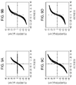
- XRD measurement results in Examples 1 to 4 and 7, and Comparative Examples 1 and 2 are shown in Figs. 7A to 7G respectively.
- An XRD two-dimensional image of Comparative Example 2 illustrated in Fig. 7G is shown in Fig. 8 .
- Cases of Examples 1 to 4 and 7, and Comparative Example 2 in which manganese is contained were as follows. Firstly, as illustrated in Fig.
- perovskite type compound oxide constituting the piezoelectric layer was randomly oriented, from the XRD two-dimensional image illustrated in Fig. 8 .
- (100) orientation was easily performed in a case where manganese was contained, and the ratio (Mn 2+ /(Mn 3+ +Mn 4+ )) of the bivalent manganese was equal to or greater than 0.31.
- P-E hysteresis was measured with an applied voltage of 10 eV to 30 eV, at a frequency of 1 kHz by using "FCE measurement system” (manufactured by Toyo Co).
- a Si single crystal substrate is exemplified as the passage formation substrate.
- the passage formation substrate may be a SOI substrate or a material such as glass. Even when any substrate is used as the passage formation substrate, deterioration due to a reaction with alkali metal derived from the piezoelectric layer is predicted. Thus, providing the zirconium oxide layer which conducts the stopper function of K or Na is meaningful.
- the ink jet recording head is exemplified and described.
- the invention may be also applied to a liquid ejecting head which ejects a liquid other than an ink.
- a liquid ejecting head include various recording heads used in an image recording apparatus such as a printer; a coloring material ejecting head used in manufacturing a color filter in a liquid crystal display and the like; an electrode material ejecting head used in forming an electrode in an organic EL display, a field emission display (FED), and the like; and a bio-organic material ejecting head used in manufacturing a bio-chip.
- the invention is not limited to the piezoelectric element mounted in the liquid ejecting head.
- the invention may be also applied to a piezoelectric element mounted in other piezoelectric element applied devices.
- An example of the piezoelectric element applied device includes a MEMS element represented by a piezoelectric MEMS element.
- an ultrasonic measurement device represented by an ultrasonic sensor and the like may be provided.
- piezoelectric element applied device is not limited to the above-described examples.
- a pyroelectric element in a piezoelectric actuator device, an ultrasonic motor, a pressure sensor, an IR sensor, and the like; and a ferroelectric element in a ferroelectric memory and the like are exemplified. These elements are just an example.
- the thickness, the width, the relative positional relationship, and the like of the constituents illustrated in the drawings, that is, the layers and the like may be exaggeratedly illustrated in describing the invention.
- the term of “being on” in the specification is not limited to the meaning that the positional relationship between the constituents is “just on”.
- an expression that "the zirconium oxide layer on the substrate” or an expression “the first electrode on the zirconium oxide layer” includes a case where other constituents are provided between the substrate and the zirconium oxide layer or between the zirconium oxide layer and the first electrode.
Landscapes
- Engineering & Computer Science (AREA)
- Chemical & Material Sciences (AREA)
- Materials Engineering (AREA)
- Ceramic Engineering (AREA)
- Manufacturing & Machinery (AREA)
- Particle Formation And Scattering Control In Inkjet Printers (AREA)
- Inorganic Compounds Of Heavy Metals (AREA)
- General Electrical Machinery Utilizing Piezoelectricity, Electrostriction Or Magnetostriction (AREA)
Applications Claiming Priority (1)
| Application Number | Priority Date | Filing Date | Title |
|---|---|---|---|
| JP2015109078A JP6521241B2 (ja) | 2015-05-28 | 2015-05-28 | 圧電素子及び圧電素子応用デバイス |
Publications (2)
| Publication Number | Publication Date |
|---|---|
| EP3098868A1 true EP3098868A1 (de) | 2016-11-30 |
| EP3098868B1 EP3098868B1 (de) | 2017-11-22 |
Family
ID=56081344
Family Applications (1)
| Application Number | Title | Priority Date | Filing Date |
|---|---|---|---|
| EP16171516.4A Active EP3098868B1 (de) | 2015-05-28 | 2016-05-26 | Piezoelektrisches element und vorrichtung mit angebrachtem piezoelektrischem element |
Country Status (4)
| Country | Link |
|---|---|
| US (1) | US10199559B2 (de) |
| EP (1) | EP3098868B1 (de) |
| JP (1) | JP6521241B2 (de) |
| CN (1) | CN106206932B (de) |
Cited By (3)
| Publication number | Priority date | Publication date | Assignee | Title |
|---|---|---|---|---|
| EP3336912A1 (de) * | 2016-12-19 | 2018-06-20 | Seiko Epson Corporation | Bauelement mit piezoelektrischem film |
| EP3364472A1 (de) * | 2017-02-15 | 2018-08-22 | Seiko Epson Corporation | Piezoelektrisches element und vorrichtung mit angewandtem piezoelektrischem element |
| EP3364471A4 (de) * | 2015-10-16 | 2019-10-23 | Sciocs Company Limited | Mehrschichtiges substrat mit piezoelektrischer dünnschicht, piezoelektrisches dünnschichtelement und verfahren zur herstellung davon |
Families Citing this family (7)
| Publication number | Priority date | Publication date | Assignee | Title |
|---|---|---|---|---|
| WO2017164413A1 (en) * | 2016-03-25 | 2017-09-28 | Canon Kabushiki Kaisha | Method of manufacturing an oscillator, method of manufacturing an oscillatory wave driving apparatus, and method of manufacturing an optical apparatus |
| JP2018129402A (ja) * | 2017-02-08 | 2018-08-16 | セイコーエプソン株式会社 | 圧電素子及びその製造方法 |
| JP6932966B2 (ja) * | 2017-03-28 | 2021-09-08 | セイコーエプソン株式会社 | 圧電素子及び圧電素子応用デバイス |
| JP6953810B2 (ja) * | 2017-06-09 | 2021-10-27 | セイコーエプソン株式会社 | 圧電素子、及び圧電素子応用デバイス |
| JP6958045B2 (ja) | 2017-07-11 | 2021-11-02 | セイコーエプソン株式会社 | 圧電素子およびその製造方法、ならびに圧電素子応用デバイス |
| WO2019093092A1 (ja) * | 2017-11-09 | 2019-05-16 | 株式会社村田製作所 | 圧電部品、センサおよびアクチュエータ |
| CN109809499B (zh) * | 2019-01-09 | 2021-03-19 | 蜂巢能源科技有限公司 | 富锂正极材料前驱体、富锂正极材料及其制备方法 |
Citations (4)
| Publication number | Priority date | Publication date | Assignee | Title |
|---|---|---|---|---|
| JPS56120180A (en) * | 1981-02-12 | 1981-09-21 | Nec Corp | Piezoelectric porcelain |
| US20140084754A1 (en) * | 2012-09-21 | 2014-03-27 | Tdk Corporation | Thin film piezoelectric device |
| JP2014060267A (ja) | 2012-09-18 | 2014-04-03 | Hitachi Metals Ltd | 圧電膜素子及びそれを備えた圧電膜デバイス |
| JP2014065317A (ja) | 2014-01-17 | 2014-04-17 | Seiko Epson Corp | 圧電素子及び液体噴射ヘッド |
Family Cites Families (10)
| Publication number | Priority date | Publication date | Assignee | Title |
|---|---|---|---|---|
| JPS5612080A (en) | 1979-07-09 | 1981-02-05 | Hitachi Ltd | Full-enclose type motor-driven compressor |
| JP5021595B2 (ja) * | 2007-10-19 | 2012-09-12 | 日本碍子株式会社 | 圧電/電歪磁器組成物及び圧電/電歪素子 |
| US8022604B2 (en) | 2007-10-19 | 2011-09-20 | Ngk Insulators, Ltd. | (Li, Na, K)(Nb, Ta)O3 type piezoelectric/electrostrictive ceramic composition containing 30-50 mol% Ta and piezoelectric/electrorestrictive device containing the same |
| JP5662888B2 (ja) | 2011-07-04 | 2015-02-04 | 太陽誘電株式会社 | 多積層圧電セラミックス部品 |
| JP6249669B2 (ja) * | 2012-08-27 | 2017-12-20 | キヤノン株式会社 | 圧電材料、圧電素子、および電子機器 |
| JP6315883B2 (ja) | 2012-12-26 | 2018-04-25 | キヤノン株式会社 | 圧電素子、振動波モーター用ステーター |
| CN103265289B (zh) * | 2013-05-14 | 2016-05-11 | 齐齐哈尔大学 | 一种锰掺杂铌酸钾钠基无铅压电薄膜的制备方法 |
| WO2015033791A1 (ja) * | 2013-09-09 | 2015-03-12 | 株式会社村田製作所 | 圧電薄膜素子及びその製造方法 |
| US9022532B1 (en) * | 2013-10-21 | 2015-05-05 | Tdk Corporation | Piezoelectric element, piezoelectric actuator, piezoelectric sensor, hard disk drive, and ink-jet printer device |
| WO2015079372A1 (en) * | 2013-11-29 | 2015-06-04 | Semiconductor Energy Laboratory Co., Ltd. | Lithium-manganese composite oxide and secondary battery |
-
2015
- 2015-05-28 JP JP2015109078A patent/JP6521241B2/ja active Active
-
2016
- 2016-03-30 CN CN201610191452.1A patent/CN106206932B/zh active Active
- 2016-04-25 US US15/137,240 patent/US10199559B2/en active Active
- 2016-05-26 EP EP16171516.4A patent/EP3098868B1/de active Active
Patent Citations (4)
| Publication number | Priority date | Publication date | Assignee | Title |
|---|---|---|---|---|
| JPS56120180A (en) * | 1981-02-12 | 1981-09-21 | Nec Corp | Piezoelectric porcelain |
| JP2014060267A (ja) | 2012-09-18 | 2014-04-03 | Hitachi Metals Ltd | 圧電膜素子及びそれを備えた圧電膜デバイス |
| US20140084754A1 (en) * | 2012-09-21 | 2014-03-27 | Tdk Corporation | Thin film piezoelectric device |
| JP2014065317A (ja) | 2014-01-17 | 2014-04-17 | Seiko Epson Corp | 圧電素子及び液体噴射ヘッド |
Non-Patent Citations (2)
| Title |
|---|
| MATSUDA ET AL., JAPANESE JOURNAL OF APPLIED PHYSICS, vol. 51, 2012 |
| WONGSAENMAI S ET AL: "Crystal structure and ferroelectric properties of Mn-doped ((KaNa)Li)NbOlead-free ceramics", CURRENT APPLIED PHYSICS, NORTH-HOLLAND, AMSTERDAM, NL, vol. 12, no. 2, 19 July 2011 (2011-07-19), pages 418 - 421, XP028110366, ISSN: 1567-1739, [retrieved on 20110727], DOI: 10.1016/J.CAP.2011.07.040 * |
Cited By (5)
| Publication number | Priority date | Publication date | Assignee | Title |
|---|---|---|---|---|
| EP3364471A4 (de) * | 2015-10-16 | 2019-10-23 | Sciocs Company Limited | Mehrschichtiges substrat mit piezoelektrischer dünnschicht, piezoelektrisches dünnschichtelement und verfahren zur herstellung davon |
| US11107971B2 (en) | 2015-10-16 | 2021-08-31 | Sumitomo Chemical Company, Limited | Laminated substrate with piezoelectric thin film, piezoelectric thin film element and method for manufacturing this element |
| EP3336912A1 (de) * | 2016-12-19 | 2018-06-20 | Seiko Epson Corporation | Bauelement mit piezoelektrischem film |
| EP3364472A1 (de) * | 2017-02-15 | 2018-08-22 | Seiko Epson Corporation | Piezoelektrisches element und vorrichtung mit angewandtem piezoelektrischem element |
| US10181555B2 (en) | 2017-02-15 | 2019-01-15 | Seiko Epson Corporation | Piezoelectric element and piezoelectric element applied device |
Also Published As
| Publication number | Publication date |
|---|---|
| CN106206932B (zh) | 2019-01-15 |
| JP2016225422A (ja) | 2016-12-28 |
| CN106206932A (zh) | 2016-12-07 |
| US20170345994A1 (en) | 2017-11-30 |
| JP6521241B2 (ja) | 2019-05-29 |
| EP3098868B1 (de) | 2017-11-22 |
| US10199559B2 (en) | 2019-02-05 |
Similar Documents
| Publication | Publication Date | Title |
|---|---|---|
| EP3098868B1 (de) | Piezoelektrisches element und vorrichtung mit angebrachtem piezoelektrischem element | |
| US10243137B2 (en) | Piezoelectric element and piezoelectric element applied device | |
| EP3073540B1 (de) | Piezoelektrisches element, anwendungsvorrichtung für piezoelektrisches element und verfahren zur herstellung eines piezoelektrischen elements | |
| US10186652B2 (en) | Piezoelectric element and piezoelectric element applied device | |
| EP3070753B1 (de) | Piezoelektrisches element, aufbringungsvorrichtung für piezoelektrisches element und herstellungsverfahren eines piezoelektrischen elements | |
| EP3336912B1 (de) | Bauelement mit piezoelektrischem film | |
| US10134977B2 (en) | Piezoelectric element, method for manufacturing the same, and piezoelectric element-applied device | |
| JP6652736B2 (ja) | 圧電素子、及び圧電素子応用デバイス | |
| US10181555B2 (en) | Piezoelectric element and piezoelectric element applied device | |
| EP3413362B1 (de) | Piezoelektrisches element und vorrichtung mit angebrachtem piezoelektrischem element | |
| US10734570B2 (en) | Piezoelectric element and piezoelectric element applied device | |
| EP3382766B1 (de) | Bauelement mit piezoelektrischer schicht | |
| JP2016192511A (ja) | 圧電素子及び圧電素子応用デバイス | |
| US20180138394A1 (en) | Piezoelectric element, piezoelectric element application device, and method of manufacturing piezoelectric element | |
| US20130106959A1 (en) | Liquid ejecting head, liquid ejecting apparatus and piezoelectric element | |
| CN117835794A (zh) | 压电基板、压电元件以及压电元件应用器件 |
Legal Events
| Date | Code | Title | Description |
|---|---|---|---|
| PUAI | Public reference made under article 153(3) epc to a published international application that has entered the european phase |
Free format text: ORIGINAL CODE: 0009012 |
|
| AK | Designated contracting states |
Kind code of ref document: A1 Designated state(s): AL AT BE BG CH CY CZ DE DK EE ES FI FR GB GR HR HU IE IS IT LI LT LU LV MC MK MT NL NO PL PT RO RS SE SI SK SM TR |
|
| AX | Request for extension of the european patent |
Extension state: BA ME |
|
| 17P | Request for examination filed |
Effective date: 20170110 |
|
| RBV | Designated contracting states (corrected) |
Designated state(s): AL AT BE BG CH CY CZ DE DK EE ES FI FR GB GR HR HU IE IS IT LI LT LU LV MC MK MT NL NO PL PT RO RS SE SI SK SM TR |
|
| GRAP | Despatch of communication of intention to grant a patent |
Free format text: ORIGINAL CODE: EPIDOSNIGR1 |
|
| INTG | Intention to grant announced |
Effective date: 20170705 |
|
| GRAS | Grant fee paid |
Free format text: ORIGINAL CODE: EPIDOSNIGR3 |
|
| GRAA | (expected) grant |
Free format text: ORIGINAL CODE: 0009210 |
|
| AK | Designated contracting states |
Kind code of ref document: B1 Designated state(s): AL AT BE BG CH CY CZ DE DK EE ES FI FR GB GR HR HU IE IS IT LI LT LU LV MC MK MT NL NO PL PT RO RS SE SI SK SM TR |
|
| REG | Reference to a national code |
Ref country code: GB Ref legal event code: FG4D |
|
| REG | Reference to a national code |
Ref country code: CH Ref legal event code: EP |
|
| REG | Reference to a national code |
Ref country code: IE Ref legal event code: FG4D |
|
| REG | Reference to a national code |
Ref country code: AT Ref legal event code: REF Ref document number: 949160 Country of ref document: AT Kind code of ref document: T Effective date: 20171215 |
|
| REG | Reference to a national code |
Ref country code: DE Ref legal event code: R096 Ref document number: 602016000874 Country of ref document: DE |
|
| REG | Reference to a national code |
Ref country code: NL Ref legal event code: MP Effective date: 20171122 |
|
| REG | Reference to a national code |
Ref country code: LT Ref legal event code: MG4D |
|
| REG | Reference to a national code |
Ref country code: AT Ref legal event code: MK05 Ref document number: 949160 Country of ref document: AT Kind code of ref document: T Effective date: 20171122 |
|
| PG25 | Lapsed in a contracting state [announced via postgrant information from national office to epo] |
Ref country code: NL Free format text: LAPSE BECAUSE OF FAILURE TO SUBMIT A TRANSLATION OF THE DESCRIPTION OR TO PAY THE FEE WITHIN THE PRESCRIBED TIME-LIMIT Effective date: 20171122 Ref country code: FI Free format text: LAPSE BECAUSE OF FAILURE TO SUBMIT A TRANSLATION OF THE DESCRIPTION OR TO PAY THE FEE WITHIN THE PRESCRIBED TIME-LIMIT Effective date: 20171122 Ref country code: NO Free format text: LAPSE BECAUSE OF FAILURE TO SUBMIT A TRANSLATION OF THE DESCRIPTION OR TO PAY THE FEE WITHIN THE PRESCRIBED TIME-LIMIT Effective date: 20180222 Ref country code: LT Free format text: LAPSE BECAUSE OF FAILURE TO SUBMIT A TRANSLATION OF THE DESCRIPTION OR TO PAY THE FEE WITHIN THE PRESCRIBED TIME-LIMIT Effective date: 20171122 Ref country code: ES Free format text: LAPSE BECAUSE OF FAILURE TO SUBMIT A TRANSLATION OF THE DESCRIPTION OR TO PAY THE FEE WITHIN THE PRESCRIBED TIME-LIMIT Effective date: 20171122 Ref country code: SE Free format text: LAPSE BECAUSE OF FAILURE TO SUBMIT A TRANSLATION OF THE DESCRIPTION OR TO PAY THE FEE WITHIN THE PRESCRIBED TIME-LIMIT Effective date: 20171122 |
|
| REG | Reference to a national code |
Ref country code: FR Ref legal event code: PLFP Year of fee payment: 3 |
|
| PG25 | Lapsed in a contracting state [announced via postgrant information from national office to epo] |
Ref country code: GR Free format text: LAPSE BECAUSE OF FAILURE TO SUBMIT A TRANSLATION OF THE DESCRIPTION OR TO PAY THE FEE WITHIN THE PRESCRIBED TIME-LIMIT Effective date: 20180223 Ref country code: HR Free format text: LAPSE BECAUSE OF FAILURE TO SUBMIT A TRANSLATION OF THE DESCRIPTION OR TO PAY THE FEE WITHIN THE PRESCRIBED TIME-LIMIT Effective date: 20171122 Ref country code: RS Free format text: LAPSE BECAUSE OF FAILURE TO SUBMIT A TRANSLATION OF THE DESCRIPTION OR TO PAY THE FEE WITHIN THE PRESCRIBED TIME-LIMIT Effective date: 20171122 Ref country code: LV Free format text: LAPSE BECAUSE OF FAILURE TO SUBMIT A TRANSLATION OF THE DESCRIPTION OR TO PAY THE FEE WITHIN THE PRESCRIBED TIME-LIMIT Effective date: 20171122 Ref country code: BG Free format text: LAPSE BECAUSE OF FAILURE TO SUBMIT A TRANSLATION OF THE DESCRIPTION OR TO PAY THE FEE WITHIN THE PRESCRIBED TIME-LIMIT Effective date: 20180222 Ref country code: AT Free format text: LAPSE BECAUSE OF FAILURE TO SUBMIT A TRANSLATION OF THE DESCRIPTION OR TO PAY THE FEE WITHIN THE PRESCRIBED TIME-LIMIT Effective date: 20171122 |
|
| PG25 | Lapsed in a contracting state [announced via postgrant information from national office to epo] |
Ref country code: DK Free format text: LAPSE BECAUSE OF FAILURE TO SUBMIT A TRANSLATION OF THE DESCRIPTION OR TO PAY THE FEE WITHIN THE PRESCRIBED TIME-LIMIT Effective date: 20171122 Ref country code: CY Free format text: LAPSE BECAUSE OF FAILURE TO SUBMIT A TRANSLATION OF THE DESCRIPTION OR TO PAY THE FEE WITHIN THE PRESCRIBED TIME-LIMIT Effective date: 20171122 Ref country code: EE Free format text: LAPSE BECAUSE OF FAILURE TO SUBMIT A TRANSLATION OF THE DESCRIPTION OR TO PAY THE FEE WITHIN THE PRESCRIBED TIME-LIMIT Effective date: 20171122 Ref country code: CZ Free format text: LAPSE BECAUSE OF FAILURE TO SUBMIT A TRANSLATION OF THE DESCRIPTION OR TO PAY THE FEE WITHIN THE PRESCRIBED TIME-LIMIT Effective date: 20171122 Ref country code: SK Free format text: LAPSE BECAUSE OF FAILURE TO SUBMIT A TRANSLATION OF THE DESCRIPTION OR TO PAY THE FEE WITHIN THE PRESCRIBED TIME-LIMIT Effective date: 20171122 |
|
| REG | Reference to a national code |
Ref country code: DE Ref legal event code: R097 Ref document number: 602016000874 Country of ref document: DE |
|
| PG25 | Lapsed in a contracting state [announced via postgrant information from national office to epo] |
Ref country code: PL Free format text: LAPSE BECAUSE OF FAILURE TO SUBMIT A TRANSLATION OF THE DESCRIPTION OR TO PAY THE FEE WITHIN THE PRESCRIBED TIME-LIMIT Effective date: 20171122 Ref country code: IT Free format text: LAPSE BECAUSE OF FAILURE TO SUBMIT A TRANSLATION OF THE DESCRIPTION OR TO PAY THE FEE WITHIN THE PRESCRIBED TIME-LIMIT Effective date: 20171122 Ref country code: SM Free format text: LAPSE BECAUSE OF FAILURE TO SUBMIT A TRANSLATION OF THE DESCRIPTION OR TO PAY THE FEE WITHIN THE PRESCRIBED TIME-LIMIT Effective date: 20171122 |
|
| PLBE | No opposition filed within time limit |
Free format text: ORIGINAL CODE: 0009261 |
|
| STAA | Information on the status of an ep patent application or granted ep patent |
Free format text: STATUS: NO OPPOSITION FILED WITHIN TIME LIMIT |
|
| 26N | No opposition filed |
Effective date: 20180823 |
|
| PG25 | Lapsed in a contracting state [announced via postgrant information from national office to epo] |
Ref country code: SI Free format text: LAPSE BECAUSE OF FAILURE TO SUBMIT A TRANSLATION OF THE DESCRIPTION OR TO PAY THE FEE WITHIN THE PRESCRIBED TIME-LIMIT Effective date: 20171122 |
|
| REG | Reference to a national code |
Ref country code: BE Ref legal event code: MM Effective date: 20180531 |
|
| PG25 | Lapsed in a contracting state [announced via postgrant information from national office to epo] |
Ref country code: MC Free format text: LAPSE BECAUSE OF FAILURE TO SUBMIT A TRANSLATION OF THE DESCRIPTION OR TO PAY THE FEE WITHIN THE PRESCRIBED TIME-LIMIT Effective date: 20171122 |
|
| REG | Reference to a national code |
Ref country code: IE Ref legal event code: MM4A |
|
| PG25 | Lapsed in a contracting state [announced via postgrant information from national office to epo] |
Ref country code: LU Free format text: LAPSE BECAUSE OF NON-PAYMENT OF DUE FEES Effective date: 20180526 |
|
| PG25 | Lapsed in a contracting state [announced via postgrant information from national office to epo] |
Ref country code: IE Free format text: LAPSE BECAUSE OF NON-PAYMENT OF DUE FEES Effective date: 20180526 |
|
| PG25 | Lapsed in a contracting state [announced via postgrant information from national office to epo] |
Ref country code: BE Free format text: LAPSE BECAUSE OF NON-PAYMENT OF DUE FEES Effective date: 20180531 |
|
| REG | Reference to a national code |
Ref country code: CH Ref legal event code: PL |
|
| PG25 | Lapsed in a contracting state [announced via postgrant information from national office to epo] |
Ref country code: LI Free format text: LAPSE BECAUSE OF NON-PAYMENT OF DUE FEES Effective date: 20190531 Ref country code: MT Free format text: LAPSE BECAUSE OF NON-PAYMENT OF DUE FEES Effective date: 20180526 Ref country code: CH Free format text: LAPSE BECAUSE OF NON-PAYMENT OF DUE FEES Effective date: 20190531 |
|
| PG25 | Lapsed in a contracting state [announced via postgrant information from national office to epo] |
Ref country code: TR Free format text: LAPSE BECAUSE OF FAILURE TO SUBMIT A TRANSLATION OF THE DESCRIPTION OR TO PAY THE FEE WITHIN THE PRESCRIBED TIME-LIMIT Effective date: 20171122 |
|
| PG25 | Lapsed in a contracting state [announced via postgrant information from national office to epo] |
Ref country code: PT Free format text: LAPSE BECAUSE OF FAILURE TO SUBMIT A TRANSLATION OF THE DESCRIPTION OR TO PAY THE FEE WITHIN THE PRESCRIBED TIME-LIMIT Effective date: 20171122 |
|
| PG25 | Lapsed in a contracting state [announced via postgrant information from national office to epo] |
Ref country code: MK Free format text: LAPSE BECAUSE OF NON-PAYMENT OF DUE FEES Effective date: 20171122 Ref country code: RO Free format text: LAPSE BECAUSE OF FAILURE TO SUBMIT A TRANSLATION OF THE DESCRIPTION OR TO PAY THE FEE WITHIN THE PRESCRIBED TIME-LIMIT Effective date: 20171122 Ref country code: HU Free format text: LAPSE BECAUSE OF FAILURE TO SUBMIT A TRANSLATION OF THE DESCRIPTION OR TO PAY THE FEE WITHIN THE PRESCRIBED TIME-LIMIT; INVALID AB INITIO Effective date: 20160526 |
|
| PG25 | Lapsed in a contracting state [announced via postgrant information from national office to epo] |
Ref country code: AL Free format text: LAPSE BECAUSE OF FAILURE TO SUBMIT A TRANSLATION OF THE DESCRIPTION OR TO PAY THE FEE WITHIN THE PRESCRIBED TIME-LIMIT Effective date: 20171122 Ref country code: IS Free format text: LAPSE BECAUSE OF FAILURE TO SUBMIT A TRANSLATION OF THE DESCRIPTION OR TO PAY THE FEE WITHIN THE PRESCRIBED TIME-LIMIT Effective date: 20180322 |
|
| REG | Reference to a national code |
Ref country code: DE Ref legal event code: R079 Ref document number: 602016000874 Country of ref document: DE Free format text: PREVIOUS MAIN CLASS: H01L0041187000 Ipc: H10N0030853000 |
|
| REG | Reference to a national code |
Ref country code: FR Ref legal event code: PLFP Year of fee payment: 8 |
|
| PGFP | Annual fee paid to national office [announced via postgrant information from national office to epo] |
Ref country code: FR Payment date: 20230411 Year of fee payment: 8 Ref country code: DE Payment date: 20230331 Year of fee payment: 8 |
|
| PGFP | Annual fee paid to national office [announced via postgrant information from national office to epo] |
Ref country code: GB Payment date: 20230406 Year of fee payment: 8 |