EP3098369A1 - Schlüssel - Google Patents
Schlüssel Download PDFInfo
- Publication number
- EP3098369A1 EP3098369A1 EP16169710.7A EP16169710A EP3098369A1 EP 3098369 A1 EP3098369 A1 EP 3098369A1 EP 16169710 A EP16169710 A EP 16169710A EP 3098369 A1 EP3098369 A1 EP 3098369A1
- Authority
- EP
- European Patent Office
- Prior art keywords
- key
- data carrier
- bit
- key bit
- data
- Prior art date
- Legal status (The legal status is an assumption and is not a legal conclusion. Google has not performed a legal analysis and makes no representation as to the accuracy of the status listed.)
- Granted
Links
Images

Classifications
-
- E—FIXED CONSTRUCTIONS
- E05—LOCKS; KEYS; WINDOW OR DOOR FITTINGS; SAFES
- E05B—LOCKS; ACCESSORIES THEREFOR; HANDCUFFS
- E05B19/00—Keys; Accessories therefor
- E05B19/04—Construction of the bow or head of the key; Attaching the bow to the shank
-
- E—FIXED CONSTRUCTIONS
- E05—LOCKS; KEYS; WINDOW OR DOOR FITTINGS; SAFES
- E05B—LOCKS; ACCESSORIES THEREFOR; HANDCUFFS
- E05B19/00—Keys; Accessories therefor
- E05B19/24—Key distinguishing marks
-
- E—FIXED CONSTRUCTIONS
- E05—LOCKS; KEYS; WINDOW OR DOOR FITTINGS; SAFES
- E05B—LOCKS; ACCESSORIES THEREFOR; HANDCUFFS
- E05B19/00—Keys; Accessories therefor
- E05B19/26—Use of special materials for keys
-
- E—FIXED CONSTRUCTIONS
- E05—LOCKS; KEYS; WINDOW OR DOOR FITTINGS; SAFES
- E05B—LOCKS; ACCESSORIES THEREFOR; HANDCUFFS
- E05B47/00—Operating or controlling locks or other fastening devices by electric or magnetic means
- E05B47/0038—Operating or controlling locks or other fastening devices by electric or magnetic means using permanent magnets
- E05B47/0045—Operating or controlling locks or other fastening devices by electric or magnetic means using permanent magnets keys with permanent magnets
-
- G—PHYSICS
- G07—CHECKING-DEVICES
- G07C—TIME OR ATTENDANCE REGISTERS; REGISTERING OR INDICATING THE WORKING OF MACHINES; GENERATING RANDOM NUMBERS; VOTING OR LOTTERY APPARATUS; ARRANGEMENTS, SYSTEMS OR APPARATUS FOR CHECKING NOT PROVIDED FOR ELSEWHERE
- G07C9/00—Individual registration on entry or exit
- G07C9/00174—Electronically operated locks; Circuits therefor; Nonmechanical keys therefor, e.g. passive or active electrical keys or other data carriers without mechanical keys
- G07C2009/00968—Electronically operated locks; Circuits therefor; Nonmechanical keys therefor, e.g. passive or active electrical keys or other data carriers without mechanical keys shape of the data carrier
- G07C2009/00984—Electronically operated locks; Circuits therefor; Nonmechanical keys therefor, e.g. passive or active electrical keys or other data carriers without mechanical keys shape of the data carrier fob
-
- G—PHYSICS
- G07—CHECKING-DEVICES
- G07C—TIME OR ATTENDANCE REGISTERS; REGISTERING OR INDICATING THE WORKING OF MACHINES; GENERATING RANDOM NUMBERS; VOTING OR LOTTERY APPARATUS; ARRANGEMENTS, SYSTEMS OR APPARATUS FOR CHECKING NOT PROVIDED FOR ELSEWHERE
- G07C9/00—Individual registration on entry or exit
- G07C9/00174—Electronically operated locks; Circuits therefor; Nonmechanical keys therefor, e.g. passive or active electrical keys or other data carriers without mechanical keys
- G07C9/00944—Details of construction or manufacture
Definitions
- the present invention relates to the technical field of locking systems, in particular keys. More specifically, the present invention relates to so-called mechatronic keys, that is, keys in which both mechanical and electronic components are combined.
- Mechatronic locking systems and mechatronic keys have been around for a while.
- mechanical components are combined with electronic components so that they can combine the advantages of pure mechanical locking systems (e.g., ruggedness) with the advantages of electronics (e.g., easier access control management, particularly in case of key loss).
- the mechatronic locking systems comprise electronic identification elements (for example a data carrier integrated in the key and a corresponding reader) which are used to check the opening authorization.
- the control of the authorizations for such keys may be made, as desired, by a combination between these electronic identification elements and mechanical identification elements (e.g., the cuts on the key bit) or solely by the electronic identification elements.
- the conventional keys with integrated data carriers typically have an opening in the key cradle into which the data carrier can be inserted and closed by a removable cover. In this way, all mechanical elements of the key prefabricated and the data carrier can then be integrated into the key after programming and adaptation to the desired application. Thus, the production of keys can be simplified.
- the object of the present invention to provide a new key which does not have these and other disadvantages of the prior art. It is in particular the object of the present invention to propose a key in which unauthorized manipulation or influencing of the data stored on the data carrier integrated therein is made impossible or at least made more difficult despite a simple structure and handling. In addition, this key should also be inexpensive to produce and as versatile as possible.
- a key comprising a key chalk composed of a first element and a second element Reiden, a key bit and a data carrier for the electronic storage of data, wherein the data from the data carrier to a control module are transferable, in which the first element of the circle and / or the second element of the circle of the key are formed such that the data carrier between the first element Reidenelement and the second element Re is enclosable, and that the crayon with the disk by the positioning of the key bit is lockable.
- the advantage of this invention is, in particular, that the data carrier in the inventive key between the two components of the key crayons are positioned so that these two elements Reiden both for the maintenance and for the backup of the disk can be used. At the same time the locking of the key crop, so the final composition and assembly of the key is achieved by positioning the key bit. Consequently, in the inventive key, if desired, be completely dispensed with additional fasteners.
- the key crop is preferably designed in such a way that physical access to the data carrier when the key crop is locked is not possible.
- This design of the key can be used to guarantee the security and integrity of the integrated data carrier and thus also the data stored on the integrated data carrier in a simple manner.
- a blocking element is provided and can be positioned in the key crop such that the blocking element is at least partially damaged when removing the key bit. Thanks to such a structure of a key according to the invention, the security and integrity of the data stored on the integrated data carrier can be further improved. In fact, in case of damage to the barrier element immediately on an attempted or manipulated key can be concluded, which can lead to the fact that safety-critical risks, for example, by adjusting the access and security authorities to be removed.
- the key has an optical identification element.
- the optical identification element can be formed exchangeable. This allows different (otherwise identical looking) keys to be distinguished in a simple way.
- the identification element can be an exchangeable colored insert which can be inserted into a corresponding receptacle in the key bit.
- the first Reidenelement has a recess for receiving the data carrier and the second Reidenelements. This simplifies the mounting of the data carrier in the key crop.
- the first element of the element and / or the second element of the element can have reception elements for the key bit.
- the positioning of the key bit and the locking of the key chalk to complete the key can also be simplified.
- the key of the inventive key may be at least partially made of plastic.
- the plastic has several advantages, which recommend it for the production of the key cereals. These include, for example, a relatively simple production of different, even complex shapes and a cheap production.
- the data carrier in the key according to the invention can typically be an RFID or an NFC transponder.
- the radio-frequency identification or RFID or the near field communication or NFC technologies are due to their robustness, low energy consumption and fairly high security of data transmission very well suited for the transmission of stored on the disk of the inventive key data to the control module, where the identification of the key and the corresponding access authorization are checked.
- These control modules can typically be integrated into the fitting or cylinder, but there are also systems in which the control of data stored on the disk is ensured by mobile or eg in the wall integrated devices.
- the use of the inventive key with most existing locking systems can be ensured in this way, as they are also based in many cases on the RFID or NFC technologies.
- the key according to the invention can be constructed so that the key bit comprises a mechanically and / or magnetically readable identification code.
- the inventive key can also be used in purely mechanical or magnetic locking systems.
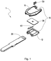
- FIGS. 1 and 2 schematically illustrates a key according to an embodiment of the present invention in an exploded view.
- This key 1 comprises in the usual way a key bit 10 and a key bit 20.
- This key bit 20 of the key 1 may also have, as with ordinary keys incisions or other similar coding elements which can be mechanically or magnetically read in a known manner. For reasons of clarity, these known per se coding elements have been omitted in the figures.
- the key 1 in addition to the key bit 10 and the key bit 20, the key 1 according to the invention also comprises a data carrier 30 on which data can be stored electronically and transmitted wirelessly to a control module.
- This data carrier 30 can be any devices which can store data in an electronic manner and deliver it wirelessly as needed to a suitable reading device, for example an RFID or NFC transponder.
- a suitable reading device for example an RFID or NFC transponder.
- the use of such transponders in mechatronic keys and locking systems and the corresponding authorization control by the control module is also known per se, so that a detailed description of these elements of the key 1 or the corresponding locking system is likewise omitted.
- the key 10 of the key 1 comprises a first element Re 11 and a second element Re 12, from which the key 10 can be assembled.
- the first element Reiden 11 specifically has a recess 13 which is dimensioned so that the disk 30 and the second Reidenelement 12 can accommodate.
- the composition or the assembly of the key 1 can in FIG. 2 be well understood.
- the first element 11 is initially provided Reidenelement with the upwardly open receiving recess 13.
- this recess 13 is then, as indicated by the arrow, the disk 30 is inserted.
- the recess 13 in the first element Reiden 11 (with the data carrier 20 therein) is then completed by the second element Re 12.
- the first Reidenelement 11 and the second Reidenelement 12 fit together in such a way that after joining these two elements 11, 12 a flush key 10 with the integrated therein disk 30 is formed.
- first Reidenelement 11 and the second Reidenelement 12 also receiving elements 14, 15, 16 for the key bit 20 on.
- these receiving elements 14, 15, 16 are designed to be in the assembled state of the key crest 10 (such as in FIG FIG. 3 illustrated) form a channel 17 into which the key bit 20 can be inserted, as indicated by the arrow in FIG FIG. 3 is illustrated.
- Self-explanatory is the fact that the dimensions and / or the shape of the hymnbarts 20 and the two elements Re 11, 12, of which the crayon 10 is composed, are matched to each other, so that the key bit 20 in the provided receptacle 17 of the crayon 10th finds a suitable seat. This positioning of the key bit 20 in the key 10 leads to a locking of the key 10 cereals with the built-in disk 30th
- This structure of the key 1 according to the invention and / or its key crayon 10 makes it possible for physical access to the inserted data carrier 30 not to be possible (or only by a complete disassembly of the key 1) when the crayon 10 is locked. As a result, the security of the data stored on the data carrier 30 can be massively improved.
- a locking element 40 may be provided in the key 1.
- the blocking element 40 is not mandatory and it should therefore be emphasized that the blocking element 40 can also be omitted in an embodiment of the present invention. If present, this locking element 40 is positionable in the key collar 10 of the key such that it is at least partially irreparably damaged when removing the key bit 20. As a result, a manipulation of the key 1 or of the data carrier 30 integrated therein can be easily recognized.
- the locking member 40 has a special shape, with a projection 41 which cooperates with the key bit 20, as just explained.
- a recess 18 matching the shape of the blocking element 40 is provided in the key ridge 10 (or in the second element 12).
- This locking element 40 is inserted after insertion of the data carrier 30 in the recess 13 of the first element Re 11, but before the onset of the second element Re 12 and the locking of the crayon 10 in the corresponding recess 18 in the second element 12.
- the blocking element 40 like the data carrier 30, is located in the interior of the key crest 10.
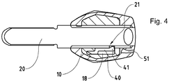
- the key bit 20 in turn has a recess 21 on its side edge, which is positioned so that it is located after the insertion of the key bit 20 in the crayon 10 just before the projection 41.
- the projection 41 of the locking element 40 engages in the recess 21 of the key bit 20, whereby a connection of these two elements is formed.
- the locking element 40 can be arranged so that it has a bias, which is its engagement in the recess 21st facilitated. This bias can also be used in particular to make it impossible to lead the projection 41 out of the recess 21. Thanks to this structure of the locking element 20, forcibly removing the key bit 20 from the key bit 10 inevitably leads to irreversible damage to the blocking element 40, so that any manipulation of the key 1 can be easily recognized.
- the key ridge 10 of the key 1 has a recess 51 into which an optical identification element 50 can be inserted.
- This optical identification element 50 may be, for example, a colored element which can be inserted into and removed from the recess 51.
- a suitable choice of the color of the element 50 may be used to identify various otherwise identical-looking keys (e.g., blue for the house key and red for the key from the workstation, etc.).
- other characteristics of the identification element 50 e.g., material, texture, etc.
- the identification element 50 can also be made interchangeable as needed.
Landscapes
- Lock And Its Accessories (AREA)
Abstract
Description
- Die vorliegende Erfindung bezieht sich auf das technische Gebiet der Schliesssysteme, insbesondere auf Schlüssel. Genauer gesagt bezieht sich die vorliegende Erfindung auf so genannte mechatronische Schlüssel, also Schlüssel, bei welchen sowohl mechanische als auch elektronische Komponenten miteinander kombiniert sind.
- Mechatronische Schliesssysteme und mechatronische Schlüssel gibt es schon seit einer Weile. In solchen mechatronischen Systemen sind mechanische Komponenten mit elektronischen Komponenten kombiniert, so dass diese die Vorteile von reinen mechanischen Schliessanlagen (z.B. die Robustheit) mit den Vorteilen der Elektronik (z.B. einfachere Verwaltung der Zutrittsrechte, insbesondere bei Schlüsselverlust) vereinen können.
- Zu diesem Zweck umfassen die mechatronischen Schliesssysteme elektronische Identifikationselemente (zum Beispiel einen in den Schlüssel integrierten Datenträger und einen entsprechenden Leser), welche zur Prüfung der Schliess- bzw. Öffnungsberechtigung benutzt werden. Die Kontrolle der Berechtigungen bei solchen Schlüsseln kann nach Wahl durch eine Kombination zwischen diesen elektronischen Identifikationselementen und mechanischen Identifikationselementen (z.B. den Einschnitten auf dem Schlüsselbart) oder aber ausschliesslich durch die elektronischen Identifikationselemente vorgenommen werden.
- Die herkömmlichen Schlüsseln mit integrierten Datenträgern weisen typischerweise eine Öffnung in der Schlüsselreide auf, in welche der Datenträger eingeführt und durch einen wiederentfernbaren Deckel abgeschlossen werden kann. Auf diese Weise können alle mechanischen Elemente des Schlüssels vorfabriziert werden und der Datenträger kann dann nach der Programmierung und Anpassung an die gewünschte Anwendung in den Schlüssel integriert werden. Damit kann die Herstellung von Schlüsseln vereinfacht werden.
- Diese Methode hat jedoch auch einige Nachteile. So kann zwar eine flexible und einfache Personalisierung von Schlüsseln gewährleistet werden, jedoch nur auf Kosten der erhöhten Sicherheit. In der Tat können die Datenträger bei diesen herkömmlichen Schlüsseln auf eine relativ einfache Weise aus der Schlüsselreide herausgenommen, manipuliert oder gar durch andere Datenträger ersetzt werden.
- Es ist daher die Aufgabe der vorliegenden Erfindung, einen neuen Schlüssel zur Verfügung zu stellen, welcher diese und andere Nachteile des Standes der Technik nicht aufweisen. Es ist insbesondere die Aufgabe der vorliegenden Erfindung, einen Schlüssel vorzuschlagen, bei welchem eine unerlaubte Manipulation bzw. Beeinflussung der auf dem darin integrierten Datenträger gespeicherten Daten trotz einer einfachen Struktur und Handhabung verunmöglicht oder zumindest erschwert ist. Zusätzlich sollte dieser Schlüssel auch kostengünstig herstellbar und möglichst vielfältig einsetzbar sein.
- Gemäss der vorliegenden Erfindung werden diese Ziele insbesondere durch die Elemente des unabhängigen Anspruchs erreicht. Weitere vorteilhafte Ausführungsformen gehen ausserdem aus den abhängigen Ansprüchen und der Beschreibung hervor.
- Diese Ziele der Erfindung werden vor allem durch einen Schlüssel erreicht, umfassend eine aus einem ersten Reidenelement und einem zweiten Reidenelement zusammensetzbare Schlüsselreide, einen Schlüsselbart sowie einen Datenträger zur elektronischen Speicherung von Daten, wobei die Daten aus dem Datenträger an ein Kontrollmodul übertragbar sind, bei welchem das erste Reidenelement und/oder das zweite Reidenelement der Schlüsselreide derart ausgebildet sind, dass der Datenträger zwischen dem ersten Reidenelement und dem zweiten Reidenelement einschliessbar ist, und dass die Schlüsselreide mit dem Datenträger durch das Positionieren des Schlüsselbarts verriegelbar ist.
- Der Vorteil dieser Erfindung liegt insbesondere darin, dass der Datenträger im erfindungsgemässen Schlüssel zwischen den beiden Bestandelementen der Schlüsselreide positioniert werden, so dass diese beiden Reidenelemente sowohl für den Halt als auch für die Sicherung des Datenträgers verwendet werden können. Gleichzeitig wird die Verriegelung der Schlüsselreide, also die definitive Zusammensetzung und Montage des Schlüssels durch das Positionieren des Schlüsselbarts erreicht. Folglich kann beim erfindungsgemässen Schlüssel, wenn gewünscht, vollkommen auf zusätzliche Befestigungselemente verzichtet werden.
- Bevorzugt ist die Schlüsselreide derart ausgebildet, dass ein physischer Zugriff auf den Datenträger bei verriegelter Schlüsselreide nicht möglich ist. Durch diese Bauweise des Schlüssels kann die Sicherheit und Unversehrtheit des integrierten Datenträgers und damit auch die der auf dem integrierten Datenträger gespeicherten Daten auf eine einfache Art und Weise garantiert werden.
- In einer bevorzugten Ausführungsvariante der Erfindung ist ein Sperrelement vorgesehen und in der Schlüsselreide derart positionierbar, dass das Sperrelement beim Entfernen des Schlüsselbarts mindestens teilweise beschädigbar ist. Dank eines solchen Aufbaus eines erfindungsgemässen Schlüssels kann die Sicherheit und Unversehrtheit der auf dem integrierten Datenträger gespeicherten Daten noch weiter verbessert werden. In der Tat kann bei einer Beschädigung des Sperrelements sofort auf eine versuchte bzw. erfolgte Manipulation des Schlüssels geschlossen werden, was dazu führen kann, dass sicherheitskritische Risiken beispielsweise durch eine Anpassung der Zutritts- und Sicherheitsbefugnisse aus dem Weg geräumt werden.
- In einer anderen Ausführungsvariante der vorliegenden Erfindung weist die Schlüsselreide ein optisches Identifikationselement aufweist. Bevorzugt kann das optische Identifikationselement austauschbar ausgebildet sein. Dadurch können verschiedene (ansonsten gleich aussehende) Schlüssel auf eine einfache Weise voneinander unterschieden werden. Wie weiter erläutert wird kann sich um das Identifikationselement um einen austauschbaren farbigen Einsatz handeln, welcher in eine entsprechende Aufnahme in der Schlüsselreide eingeführt werden kann.
- In einer bevorzugten Ausführungsvariante der vorliegenden Erfindung weist das erste Reidenelement eine Vertiefung zur Aufnahme des Datenträgers und des zweiten Reidenelements auf. Damit wird die Montage des Datenträgers in der Schlüsselreide vereinfacht. Ausserdem können das erste Reidenelement und/oder das zweite Reidenelement Aufnahmeelemente für den Schlüsselbart aufweisen. Damit können zudem das Positionieren des Schlüsselbarts und die Verriegelung der Schlüsselreide zur Fertigstellung des Schlüssels ebenfalls vereinfacht werden.
- Die Schlüsselreide des erfindungsgemässen Schlüssels kann mindestens teilweise aus Kunststoff hergestellt. Der Kunststoff hat verschiedene Vorteile, welche ihn für die Herstellung der Schlüsselreide empfehlen. Dazu gehören zum Beispiel eine relativ einfache Herstellung verschiedener, auch komplexer Formen und eine günstige Fertigung.
- Der Datenträger im erfindungsgemässen Schlüssel kann typischerweise ein RFID- bzw. ein NFC-Transponder sein. Die Radio-frequency identification oder RFID- bzw. die Near field communication oder NFC-Technologien sind auf Grund ihrer Robustheit, kleinem Energieverbrauch und ziemlich grosser Sicherheit der Datenübertragung sehr gut geeignet für die Übertragung der auf dem Datenträger des erfindungsgemässen Schlüssels gespeicherten Daten zum Kontrollmodul, wo die Identifikation des Schlüssels und die entsprechende Zutrittsberechtigung überprüft werden. Diese Kontrollmodule können typischerweise in den Beschlag bzw. den Zylinder integriert sein, aber es gibt auch Systeme, bei welchen die Kontrolle der auf dem Datenträger gespeicherten Daten durch mobile oder z.B. in die Wand integrierte Geräte gewährleistet wird. Zudem kann auf diese Weise die Verwendung des erfindungsgemässen Schlüssels mit den meisten bestehenden Schliesssystemen gewährleistet werden, da diese in vielen Fällen ebenfalls auf die RFID- bzw. NFC-Technologien basieren.
- Der erfindungsgemässe Schlüssel kann selbstverständlich so aufgebaut sein, dass der Schlüsselbart einen mechanisch und/oder magnetisch lesbaren Identifikationscode umfasst. Damit kann der erfindungsgemässe Schlüssel auch in rein mechanischen bzw. magnetischen Schliesssystemen verwendet werden.
- Weitere Einzelheiten der Erfindung gehen aus der nun folgenden Beschreibung besonderer bzw. bevorzugter Ausführungsvarianten der Erfindung hervor, welche in den beigelegten Zeichnungen dargestellt sind. Der Beschreibung lassen sich auch die weiteren Vorteile der vorliegenden Erfindung entnehmen sowie Anregungen und Vorschläge, wie der Erfindungsgegenstand im Rahmen des Beanspruchten abgeändert oder auch weiterentwickelt werden könnte.
- Die Erfindung wird nun an Hand von einem Ausführungsbeispiel unter Bezugnahme auf die folgenden beiliegenden Zeichnungen näher erläutert werden.
- In den Zeichnungen stellen dar:
-
Figuren 1 und2 perspektivische schematische Explosionsansichten eines Schlüssels gemäss einem Ausführungsbeispiel der Erfindung;Figur 1 in einer Oberansicht undFigur 2 in einer Unteransicht; -
Figur 3 eine perspektivische schematische Ansicht des Schlüssels ausFigur 2 , bevor der Schlüsselbart mit der Schlüsselreide verbunden wird; und -
Figur 4 einen Querschnitt durch den Schlüssels aus den vorhergehenden Figuren in der Ansicht von oben. - In
Figuren 1 und2 wird schematisch ein Schlüssel gemäss einem Ausführungsbeispiel der vorliegenden Erfindung in einer Explosionsansicht illustriert. Dieser Schlüssel 1 umfasst in gewöhnlicher Weise eine Schlüsselreide 10 und einen Schlüsselbart 20. Dieser Schlüsselbart 20 des Schlüssels 1 kann ebenfalls wie bei gewöhnlichen Schlüsseln Einschnitte oder andere ähnliche Kodierungselemente aufweisen, welche in bekannter Weise mechanisch bzw. magnetisch gelesen werden können. Aus Übersichtsgründen sind diese an sich bekannten Kodierungselemente in den Figuren ausgelassen worden. - Neben der Schlüsselreide 10 und dem Schlüsselbart 20 umfasst der erfindungsgemässe Schlüssel 1 auch einen Datenträger 30 auf welchem Daten elektronisch gespeichert und drahtlos an ein Kontrollmodul übertragen werden können. Bei diesem Datenträger 30 kann sich um beliebige Vorrichtungen handeln, welche Daten in elektronischer Weise speichern und nach Bedarf an ein geeignetes Lesegerät drahtlos abgeben können, zum Beispiel um einen RFIDoder NFC-Transponder. Die Verwendung von solchen Transponder in mechatronischen Schlüsseln und Schliesssystemen und die entsprechende Berechtigungskontrolle durch das Kontrollmodul ist an sich ebenfalls bekannt, so dass eine detaillierte Beschreibung dieser Elemente des Schlüssels 1 bzw. des entsprechenden Schliesssystems ebenfalls ausgelassen wird.
- Wie in
Figuren 1 und2 gesehen werden kann, umfasst die Schlüsselreide 10 des Schlüssels 1 ein erstes Reidenelement 11 und ein zweites Reidenelement 12, aus welchem die Schlüsselreide 10 zusammengebaut werden kann. Das erste Reidenelement 11 weist spezifisch eine Vertiefung 13 auf, welche so dimensioniert ist, dass den Datenträger 30 und das zweite Reidenelement 12 aufnehmen kann. - Die Zusammensetzung bzw. die Montage des Schlüssels 1 kann in
Figur 2 gut nachvollzogen werden. Hierzu wird zunächst das erste Reidenelement 11 mit der nach oben geöffneten Aufnahmevertiefung 13 zur Verfügung gestellt. In diese Vertiefung 13 wird dann, wie durch den Pfeil angedeutet, der Datenträger 30 eingesetzt. Die Vertiefung 13 im ersten Reidenelement 11 (mit dem darin liegenden Datenträger 20) wird danach durch das zweite Reidenelement 12 abgeschlossen. Wie inFigur 3 gut gesehen werden kann passen das erste Reidenelement 11 und das zweite Reidenelement 12 derart zusammen, dass nach dem Zusammenfügen dieser beiden Elemente 11, 12 eine bündige Schlüsselreide 10 mit dem darin integrierten Datenträger 30 entsteht. - Wie in
Figuren 1 und2 ebenfalls gut ersichtlich ist, weisen das erste Reidenelement 11 und das zweite Reidenelement 12 ausserdem Aufnahmeelemente 14, 15, 16 für den Schlüsselbart 20 auf. Spezifisch sind diese Aufnahmeelemente 14, 15, 16 so ausgestaltet, dass sie im zusammengefügten Zustand der Schlüsselreide 10 (wie zum Beispiel inFigur 3 illustriert) einen Kanal 17 bilden, in welchen der Schlüsselbart 20 eingeführt werden kann, was durch den Pfeil inFigur 3 illustriert wird. - Selbsterklärend ist die Tatsache, dass die Dimensionen und/oder die Form des Schlüsselbarts 20 bzw. der beiden Reidenelemente 11, 12, aus welchen die Schlüsselreide 10 zusammengesetzt ist, aneinander abgestimmt sind, so dass der Schlüsselbart 20 in der vorgesehenen Aufnahme 17 der Schlüsselreide 10 einen passenden Sitz findet. Dieses Positionieren des Schlüsselbarts 20 in der Schlüsselreide 10 führt zu einer Verriegelung der Schlüsselreide 10 mit dem darin eingebauten Datenträger 30.
- Die gegenseitige Befestigung aller Bestandteile des Schlüssels 1 kann lediglich durch den passenden Sitz gewährleistet werden. Allerdings können am Schlüsselbart 20 und/oder an der Schlüsselreide 10 nach Bedarf auch passende Fixierungselemente (zum Beispiel in der Art einer Spundung) vorgesehen werden, durch welche diese beiden Bestandteile des Schlüssels 1 miteinander fest verbunden werden können. Auch denkbar wären eine Klebeverbindung durch geeignete Klebemittel oder eine andere Art der Befestigung.
- Diese Struktur des erfindungsgemässen Schlüssels 1 bzw. seiner Schlüsselreide 10 macht es möglich, dass ein physischer Zugriff auf den eingesetzten Datenträger 30 bei verriegelter Schlüsselreide 10 gar nicht (bzw. nur durch ein komplettes Auseinandernehmen des Schlüssels 1) möglich ist. Dadurch kann die Sicherheit der auf dem Datenträger 30 gespeicherten Daten massiv verbessert werden.
- Die Sicherheit der Daten kann jedoch noch weiter verbessert werden. Hierzu kann im Schlüssel 1 auch ein Sperrelement 40 vorgesehen sein. Selbstverständlich ist das Sperrelement 40 nicht zwingend und es soll daher betont werden, dass das Sperrelement 40 in einem Ausführungsbeispiel der vorliegenden Erfindung auch ausgelassen werden kann. Wenn vorhanden, ist dieses Sperrelement 40 in der Schlüsselreide 10 des Schlüssels derart positionierbar, dass es beim Entfernen des Schlüsselbarts 20 mindestens teilweise irreparabel beschädigt wird. Dadurch kann eine Manipulation des Schlüssels 1 bzw. des darin integrierten Datenträgers 30 einfach erkannt werden.
- Wie in
Figuren 1 ,2 und4 gut gesehen werden kann, hat das Sperrelement 40 eine besondere Form, mit einem Vorsprung 41, welcher mit dem Schlüsselbart 20 zusammenwirkt, wie soeben erläutert wird. Ausserdem ist in der Schlüsselreide 10 (bzw. im zweiten Reidenelement 12) eine zur Form des Sperrelements 40 passende Vertiefung 18 vorgesehen. Dieses Sperrelement 40 wird nach dem Einsetzen des Datenträgers 30 in die Vertiefung 13 des ersten Reidenelements 11, jedoch vor dem Einsetzen des zweiten Reidenelements 12 und dem Verriegeln der Schlüsselreide 10 in die entsprechende Vertiefung 18 im zweiten Reidenelement 12 eingesetzt. Somit befindet sich das Sperrelement 40, wie der Datenträger 30, im Inneren der Schlüsselreide 10. - Der Schlüsselbart 20 weist seinerseits eine Vertiefung 21 an seiner Seitenkante, welche derart positioniert ist, dass sie sich nach dem Einführen des Schlüsselbarts 20 in die Schlüsselreide 10 genau vor dem Vorsprung 41 befindet. In diesem Moment rastet der Vorsprung 41 des Sperrelements 40 in die Vertiefung 21 des Schlüsselbarts 20 ein, wodurch eine Verbindung dieser beiden Elemente entsteht. Das Sperrelement 40 kann so angeordnet werden, dass es eine Vorspannung aufweist, welche sein Einrasten in die Vertiefung 21 erleichtert. Diese Vorspannung kann insbesondere auch verwendet werden, um ein Herausführen des Vorsprungs 41 aus der Vertiefung 21 unmöglich macht. Dank dieser Struktur des Sperrelements 20 führt ein gewaltsames Herausnehmen des Schlüsselbarts 20 aus der Schlüsselreide 10 zwingend zu einer irreversiblen Beschädigung des Sperrelements 40, so dass jede Manipulation am Schlüssel 1 einfach erkannt werden kann.
- Schliesslich weist die Schlüsselreide 10 des Schlüssels 1 eine Vertiefung 51, in welche ein optisches Identifikationselement 50 eingefügt werden kann. Dieses optische Identifikationselement 50 kann beispielsweise ein farbiges Element sein, welches in die Vertiefung 51 eingeführt und aus dieser wieder herausgenommen werden kann. Eine geeignete Wahl der Farbe des Elements 50 kann zur Kennzeichnung verschiedener sonst gleich aussehender Schlüssel verwendet werden (z.B. blau für den Hausschlüssel und rot für den Schlüssel vom Arbeitsplatz, etc.). Neben der Farbe können selbstverständlich auch andere Eigenschaften des Identifikationselements 50 (z.B. Material, Oberflächenbeschaffenheit, etc.) zur Unterscheidung von Schlüsseln verwendet werden. Das Identifikationselement 50 kann nach Bedarf auch austauschbar ausgestaltet werden.
- Zum Schluss sei darauf hingewiesen, dass die hier beispielhaft beschriebenen Ausführungsvarianten nur eine Auswahl an möglichen Realisierungen der erfindungsgemässen Ideen darstellen und keinesfalls als limitierend angesehen werden sollen. Der Fachmann wird verstehen, dass noch andere Implementierungen der Erfindung und weitere Elemente möglich sind, ohne dass die wesentlichen Merkmale der Erfindung vernachlässigt werden. Insbesondere können die einzelnen Bestandteile des Schlüssels 1 in verschiedenen Materialien, Farben oder/oder Mustern angeboten werden, damit die erfindungsgemässen Schlüssel nicht nur eine praktische, sondern auch eine ästhetische Funktion erfüllen können.
Claims (10)
- Schlüssel (1), umfassend eine aus einem ersten Reidenelement (11) und einem zweiten Reidenelement (12) zusammensetzbare Schlüsselreide (10), einen Schlüsselbart (20) sowie einen Datenträger (30) zur elektronischen Speicherung von Daten, wobei die Daten aus dem Datenträger (30) an ein Kontrollmodul übertragbar sind,
dadurch gekennzeichnet,
dass das erste Reidenelement (11) und/oder das zweite Reidenelement (12) der Schlüsselreide (10) derart ausgebildet sind, dass der Datenträger (30) zwischen dem ersten Reidenelement (10) und dem zweiten Reidenelement (11) einschliessbar ist, und dass die Schlüsselreide (10) mit dem Datenträger (30) durch das Positionieren des Schlüsselbarts (20) verriegelbar ist. - Schlüssel nach Anspruch 1, dadurch gekennzeichnet, dass die Schlüsselreide (10) derart ausgebildet ist, dass ein physischer Zugriff auf den Datenträger (30) bei verriegelter Schlüsselreide (10) nicht möglich ist.
- Schlüssel nach Anspruch 1 oder 2, dadurch gekennzeichnet, dass ein Sperrelement (40) vorgesehen und in der Schlüsselreide (10) derart positionierbar ist, so dass das Sperrelement (40) beim Entfernen des Schlüsselbarts (20) mindestens teilweise beschädigbar ist.
- Schlüssel nach einem der vorangehenden Ansprüche, dadurch gekennzeichnet, dass die Schlüsselreide (10) ein optisches Identifikationselement (50) aufweist.
- Schlüssel nach Anspruch 4, dadurch gekennzeichnet, dass das optische Identifikationselement (50) austauschbar ist.
- Schlüssel nach einem der vorangehenden Ansprüche, dadurch gekennzeichnet, dass das erste Reidenelement (11) eine Vertiefung (13) zur Aufnahme des Datenträgers (30) und des zweiten Reidenelements (12) aufweist.
- Schlüssel nach einem der vorangehenden Ansprüche, dadurch gekennzeichnet, dass das erste Reidenelement (11) und/oder das zweite Reidenelement (12) Aufnahmeelemente für den Schlüsselbart (20) aufweisen.
- Schlüssel nach einem der vorangehenden Ansprüche, dadurch gekennzeichnet, dass die Schlüsselreide (10) mindestens teilweise aus Kunststoff hergestellt ist.
- Schlüssel nach einem der vorangehenden Ansprüche, dadurch gekennzeichnet, dass der Datenträger (30) ein RFID- bzw. ein NFC-Transponder ist.
- Schlüssel nach einem der vorangehenden Ansprüche, dadurch gekennzeichnet, dass der Schlüsselbart (20) einen mechanisch und/oder magnetisch lesbaren Identifikationscode umfasst.
Applications Claiming Priority (1)
| Application Number | Priority Date | Filing Date | Title |
|---|---|---|---|
| CH00683/15A CH711103A1 (de) | 2015-05-18 | 2015-05-18 | Schlüssel. |
Publications (2)
| Publication Number | Publication Date |
|---|---|
| EP3098369A1 true EP3098369A1 (de) | 2016-11-30 |
| EP3098369B1 EP3098369B1 (de) | 2018-05-09 |
Family
ID=54544857
Family Applications (1)
| Application Number | Title | Priority Date | Filing Date |
|---|---|---|---|
| EP16169710.7A Active EP3098369B1 (de) | 2015-05-18 | 2016-05-13 | Schlüssel |
Country Status (2)
| Country | Link |
|---|---|
| EP (1) | EP3098369B1 (de) |
| CH (1) | CH711103A1 (de) |
Cited By (1)
| Publication number | Priority date | Publication date | Assignee | Title |
|---|---|---|---|---|
| EP3536879A1 (de) | 2018-03-08 | 2019-09-11 | Aug. Winkhaus GmbH & Co. KG | Schlüssel und verfahren zur herstellung eines aus metall gefertigten schlüssels |
Citations (5)
| Publication number | Priority date | Publication date | Assignee | Title |
|---|---|---|---|---|
| US4349975A (en) * | 1981-03-05 | 1982-09-21 | Chubb Wayne L | Key attachment |
| JPH08270276A (ja) * | 1995-03-29 | 1996-10-15 | Clover:Kk | 鍵 |
| EP0879929A1 (de) * | 1997-05-22 | 1998-11-25 | Valeo Securite Habitacle | Ein Gehäuse bildender Schlüsselkopf mit einer elektronischen Vorrichtung |
| DE102009022636A1 (de) * | 2009-05-26 | 2010-12-02 | Volkswagen Ag | Gehäuse eines elektronischen Schlüssels |
| US20150047399A1 (en) * | 2013-08-16 | 2015-02-19 | The Hillman Group Inc. | Multi-piece key assembly |
-
2015
- 2015-05-18 CH CH00683/15A patent/CH711103A1/de unknown
-
2016
- 2016-05-13 EP EP16169710.7A patent/EP3098369B1/de active Active
Patent Citations (5)
| Publication number | Priority date | Publication date | Assignee | Title |
|---|---|---|---|---|
| US4349975A (en) * | 1981-03-05 | 1982-09-21 | Chubb Wayne L | Key attachment |
| JPH08270276A (ja) * | 1995-03-29 | 1996-10-15 | Clover:Kk | 鍵 |
| EP0879929A1 (de) * | 1997-05-22 | 1998-11-25 | Valeo Securite Habitacle | Ein Gehäuse bildender Schlüsselkopf mit einer elektronischen Vorrichtung |
| DE102009022636A1 (de) * | 2009-05-26 | 2010-12-02 | Volkswagen Ag | Gehäuse eines elektronischen Schlüssels |
| US20150047399A1 (en) * | 2013-08-16 | 2015-02-19 | The Hillman Group Inc. | Multi-piece key assembly |
Cited By (2)
| Publication number | Priority date | Publication date | Assignee | Title |
|---|---|---|---|---|
| EP3536879A1 (de) | 2018-03-08 | 2019-09-11 | Aug. Winkhaus GmbH & Co. KG | Schlüssel und verfahren zur herstellung eines aus metall gefertigten schlüssels |
| DE102018203550A1 (de) | 2018-03-08 | 2019-09-12 | Aug. Winkhaus Gmbh & Co. Kg | Schlüssel und Verfahren zur Herstellung eines aus Metall gefertigten Schlüssels |
Also Published As
| Publication number | Publication date |
|---|---|
| EP3098369B1 (de) | 2018-05-09 |
| CH711103A1 (de) | 2016-11-30 |
Similar Documents
| Publication | Publication Date | Title |
|---|---|---|
| EP0809743B1 (de) | Elektronischer schlüssel | |
| EP3049218A1 (de) | Verschluss für einen behälter | |
| EP0974719A2 (de) | Schloss, insbesondere für eine Schliessanlage | |
| EP3098369B1 (de) | Schlüssel | |
| WO2013030078A1 (de) | Mechatronische schliessvorrichtung | |
| EP3753442B1 (de) | Kartengehäuse | |
| DE102007021138A1 (de) | Montageanordnung sowie Erfassungssystem mit einer solchen Anordnung | |
| AT400605B (de) | Identifikationsträger für ein schliesssystem | |
| DE102014015280A1 (de) | Tragbarer Datenträger | |
| EP1736622A1 (de) | Knaufzylinder | |
| DE10225368C1 (de) | Schließzylinder mit kontaktloser Übertragung eines Signals | |
| DE19520791A1 (de) | Vorrichtung zum gegenseitigen Verbinden von Containern | |
| EP2268511B1 (de) | Vorrichtung zum betätigen von schlössern, insbesondere an fahrzeugen | |
| WO1996017334A1 (de) | Vorrichtung zur speicherung persönlicher identifikationsnummern | |
| EP0434176B1 (de) | Schloss-Schlüssel-Kombination | |
| EP0193814A2 (de) | Gegenstand mit Informationsträger und Verfahren zu seiner Herstellung | |
| DE4022971A1 (de) | Sicherheitsschloss mit doppelschliesszylinder | |
| EP3184005B1 (de) | Feuerwehrschlüsseldepot mit mindestens einem darin angeordneten mechanischen schlüssel | |
| DE102004033746B3 (de) | Schlosssicherung | |
| DE19527223A1 (de) | Anhänger für Schlüssel, z.B. Kraftfahrzeugschlüssel | |
| DE202007019437U1 (de) | Montageanordnung sowie Erfassungssystem mit einer solchen Anordnung | |
| EP1124207A1 (de) | Schliesssystem | |
| DE102012105084A1 (de) | Mechanisches Sicherheitsschloss | |
| DE202013104341U1 (de) | Verschluss für einen Behälter | |
| DE102009007135A1 (de) | Transportwagen |
Legal Events
| Date | Code | Title | Description |
|---|---|---|---|
| PUAI | Public reference made under article 153(3) epc to a published international application that has entered the european phase |
Free format text: ORIGINAL CODE: 0009012 |
|
| AK | Designated contracting states |
Kind code of ref document: A1 Designated state(s): AL AT BE BG CH CY CZ DE DK EE ES FI FR GB GR HR HU IE IS IT LI LT LU LV MC MK MT NL NO PL PT RO RS SE SI SK SM TR |
|
| AX | Request for extension of the european patent |
Extension state: BA ME |
|
| 17P | Request for examination filed |
Effective date: 20170420 |
|
| RBV | Designated contracting states (corrected) |
Designated state(s): AL AT BE BG CH CY CZ DE DK EE ES FI FR GB GR HR HU IE IS IT LI LT LU LV MC MK MT NL NO PL PT RO RS SE SI SK SM TR |
|
| RIC1 | Information provided on ipc code assigned before grant |
Ipc: E05B 19/24 20060101ALN20171002BHEP Ipc: E05B 19/04 20060101AFI20171002BHEP Ipc: E05B 19/26 20060101ALN20171002BHEP |
|
| GRAP | Despatch of communication of intention to grant a patent |
Free format text: ORIGINAL CODE: EPIDOSNIGR1 |
|
| INTG | Intention to grant announced |
Effective date: 20171129 |
|
| GRAS | Grant fee paid |
Free format text: ORIGINAL CODE: EPIDOSNIGR3 |
|
| GRAA | (expected) grant |
Free format text: ORIGINAL CODE: 0009210 |
|
| AK | Designated contracting states |
Kind code of ref document: B1 Designated state(s): AL AT BE BG CH CY CZ DE DK EE ES FI FR GB GR HR HU IE IS IT LI LT LU LV MC MK MT NL NO PL PT RO RS SE SI SK SM TR |
|
| REG | Reference to a national code |
Ref country code: GB Ref legal event code: FG4D Free format text: NOT ENGLISH |
|
| REG | Reference to a national code |
Ref country code: CH Ref legal event code: EP Ref country code: AT Ref legal event code: REF Ref document number: 997698 Country of ref document: AT Kind code of ref document: T Effective date: 20180515 |
|
| REG | Reference to a national code |
Ref country code: DE Ref legal event code: R096 Ref document number: 502016001016 Country of ref document: DE Ref country code: IE Ref legal event code: FG4D Free format text: LANGUAGE OF EP DOCUMENT: GERMAN |
|
| REG | Reference to a national code |
Ref country code: NL Ref legal event code: FP |
|
| REG | Reference to a national code |
Ref country code: LT Ref legal event code: MG4D |
|
| PG25 | Lapsed in a contracting state [announced via postgrant information from national office to epo] |
Ref country code: NO Free format text: LAPSE BECAUSE OF FAILURE TO SUBMIT A TRANSLATION OF THE DESCRIPTION OR TO PAY THE FEE WITHIN THE PRESCRIBED TIME-LIMIT Effective date: 20180809 Ref country code: FI Free format text: LAPSE BECAUSE OF FAILURE TO SUBMIT A TRANSLATION OF THE DESCRIPTION OR TO PAY THE FEE WITHIN THE PRESCRIBED TIME-LIMIT Effective date: 20180509 Ref country code: BG Free format text: LAPSE BECAUSE OF FAILURE TO SUBMIT A TRANSLATION OF THE DESCRIPTION OR TO PAY THE FEE WITHIN THE PRESCRIBED TIME-LIMIT Effective date: 20180809 Ref country code: SE Free format text: LAPSE BECAUSE OF FAILURE TO SUBMIT A TRANSLATION OF THE DESCRIPTION OR TO PAY THE FEE WITHIN THE PRESCRIBED TIME-LIMIT Effective date: 20180509 Ref country code: ES Free format text: LAPSE BECAUSE OF FAILURE TO SUBMIT A TRANSLATION OF THE DESCRIPTION OR TO PAY THE FEE WITHIN THE PRESCRIBED TIME-LIMIT Effective date: 20180509 Ref country code: LT Free format text: LAPSE BECAUSE OF FAILURE TO SUBMIT A TRANSLATION OF THE DESCRIPTION OR TO PAY THE FEE WITHIN THE PRESCRIBED TIME-LIMIT Effective date: 20180509 |
|
| PG25 | Lapsed in a contracting state [announced via postgrant information from national office to epo] |
Ref country code: LV Free format text: LAPSE BECAUSE OF FAILURE TO SUBMIT A TRANSLATION OF THE DESCRIPTION OR TO PAY THE FEE WITHIN THE PRESCRIBED TIME-LIMIT Effective date: 20180509 Ref country code: GR Free format text: LAPSE BECAUSE OF FAILURE TO SUBMIT A TRANSLATION OF THE DESCRIPTION OR TO PAY THE FEE WITHIN THE PRESCRIBED TIME-LIMIT Effective date: 20180810 Ref country code: HR Free format text: LAPSE BECAUSE OF FAILURE TO SUBMIT A TRANSLATION OF THE DESCRIPTION OR TO PAY THE FEE WITHIN THE PRESCRIBED TIME-LIMIT Effective date: 20180509 Ref country code: RS Free format text: LAPSE BECAUSE OF FAILURE TO SUBMIT A TRANSLATION OF THE DESCRIPTION OR TO PAY THE FEE WITHIN THE PRESCRIBED TIME-LIMIT Effective date: 20180509 |
|
| REG | Reference to a national code |
Ref country code: BE Ref legal event code: MM Effective date: 20180531 |
|
| PG25 | Lapsed in a contracting state [announced via postgrant information from national office to epo] |
Ref country code: EE Free format text: LAPSE BECAUSE OF FAILURE TO SUBMIT A TRANSLATION OF THE DESCRIPTION OR TO PAY THE FEE WITHIN THE PRESCRIBED TIME-LIMIT Effective date: 20180509 Ref country code: PL Free format text: LAPSE BECAUSE OF FAILURE TO SUBMIT A TRANSLATION OF THE DESCRIPTION OR TO PAY THE FEE WITHIN THE PRESCRIBED TIME-LIMIT Effective date: 20180509 Ref country code: DK Free format text: LAPSE BECAUSE OF FAILURE TO SUBMIT A TRANSLATION OF THE DESCRIPTION OR TO PAY THE FEE WITHIN THE PRESCRIBED TIME-LIMIT Effective date: 20180509 Ref country code: RO Free format text: LAPSE BECAUSE OF FAILURE TO SUBMIT A TRANSLATION OF THE DESCRIPTION OR TO PAY THE FEE WITHIN THE PRESCRIBED TIME-LIMIT Effective date: 20180509 Ref country code: CZ Free format text: LAPSE BECAUSE OF FAILURE TO SUBMIT A TRANSLATION OF THE DESCRIPTION OR TO PAY THE FEE WITHIN THE PRESCRIBED TIME-LIMIT Effective date: 20180509 Ref country code: SK Free format text: LAPSE BECAUSE OF FAILURE TO SUBMIT A TRANSLATION OF THE DESCRIPTION OR TO PAY THE FEE WITHIN THE PRESCRIBED TIME-LIMIT Effective date: 20180509 |
|
| REG | Reference to a national code |
Ref country code: DE Ref legal event code: R097 Ref document number: 502016001016 Country of ref document: DE |
|
| REG | Reference to a national code |
Ref country code: IE Ref legal event code: MM4A |
|
| PG25 | Lapsed in a contracting state [announced via postgrant information from national office to epo] |
Ref country code: IT Free format text: LAPSE BECAUSE OF FAILURE TO SUBMIT A TRANSLATION OF THE DESCRIPTION OR TO PAY THE FEE WITHIN THE PRESCRIBED TIME-LIMIT Effective date: 20180509 Ref country code: SM Free format text: LAPSE BECAUSE OF FAILURE TO SUBMIT A TRANSLATION OF THE DESCRIPTION OR TO PAY THE FEE WITHIN THE PRESCRIBED TIME-LIMIT Effective date: 20180509 |
|
| PLBE | No opposition filed within time limit |
Free format text: ORIGINAL CODE: 0009261 |
|
| STAA | Information on the status of an ep patent application or granted ep patent |
Free format text: STATUS: NO OPPOSITION FILED WITHIN TIME LIMIT |
|
| PG25 | Lapsed in a contracting state [announced via postgrant information from national office to epo] |
Ref country code: MC Free format text: LAPSE BECAUSE OF FAILURE TO SUBMIT A TRANSLATION OF THE DESCRIPTION OR TO PAY THE FEE WITHIN THE PRESCRIBED TIME-LIMIT Effective date: 20180509 |
|
| 26N | No opposition filed |
Effective date: 20190212 |
|
| PG25 | Lapsed in a contracting state [announced via postgrant information from national office to epo] |
Ref country code: IE Free format text: LAPSE BECAUSE OF NON-PAYMENT OF DUE FEES Effective date: 20180513 Ref country code: FR Free format text: LAPSE BECAUSE OF NON-PAYMENT OF DUE FEES Effective date: 20180709 |
|
| PG25 | Lapsed in a contracting state [announced via postgrant information from national office to epo] |
Ref country code: SI Free format text: LAPSE BECAUSE OF FAILURE TO SUBMIT A TRANSLATION OF THE DESCRIPTION OR TO PAY THE FEE WITHIN THE PRESCRIBED TIME-LIMIT Effective date: 20180509 Ref country code: BE Free format text: LAPSE BECAUSE OF NON-PAYMENT OF DUE FEES Effective date: 20180531 |
|
| PG25 | Lapsed in a contracting state [announced via postgrant information from national office to epo] |
Ref country code: AL Free format text: LAPSE BECAUSE OF FAILURE TO SUBMIT A TRANSLATION OF THE DESCRIPTION OR TO PAY THE FEE WITHIN THE PRESCRIBED TIME-LIMIT Effective date: 20180509 |
|
| PG25 | Lapsed in a contracting state [announced via postgrant information from national office to epo] |
Ref country code: MT Free format text: LAPSE BECAUSE OF FAILURE TO SUBMIT A TRANSLATION OF THE DESCRIPTION OR TO PAY THE FEE WITHIN THE PRESCRIBED TIME-LIMIT Effective date: 20180509 |
|
| PG25 | Lapsed in a contracting state [announced via postgrant information from national office to epo] |
Ref country code: TR Free format text: LAPSE BECAUSE OF FAILURE TO SUBMIT A TRANSLATION OF THE DESCRIPTION OR TO PAY THE FEE WITHIN THE PRESCRIBED TIME-LIMIT Effective date: 20180509 |
|
| PG25 | Lapsed in a contracting state [announced via postgrant information from national office to epo] |
Ref country code: PT Free format text: LAPSE BECAUSE OF FAILURE TO SUBMIT A TRANSLATION OF THE DESCRIPTION OR TO PAY THE FEE WITHIN THE PRESCRIBED TIME-LIMIT Effective date: 20180509 |
|
| PG25 | Lapsed in a contracting state [announced via postgrant information from national office to epo] |
Ref country code: CY Free format text: LAPSE BECAUSE OF FAILURE TO SUBMIT A TRANSLATION OF THE DESCRIPTION OR TO PAY THE FEE WITHIN THE PRESCRIBED TIME-LIMIT Effective date: 20180509 Ref country code: HU Free format text: LAPSE BECAUSE OF FAILURE TO SUBMIT A TRANSLATION OF THE DESCRIPTION OR TO PAY THE FEE WITHIN THE PRESCRIBED TIME-LIMIT; INVALID AB INITIO Effective date: 20160513 Ref country code: MK Free format text: LAPSE BECAUSE OF NON-PAYMENT OF DUE FEES Effective date: 20180509 |
|
| PG25 | Lapsed in a contracting state [announced via postgrant information from national office to epo] |
Ref country code: IS Free format text: LAPSE BECAUSE OF FAILURE TO SUBMIT A TRANSLATION OF THE DESCRIPTION OR TO PAY THE FEE WITHIN THE PRESCRIBED TIME-LIMIT Effective date: 20180909 |
|
| PGFP | Annual fee paid to national office [announced via postgrant information from national office to epo] |
Ref country code: LU Payment date: 20210519 Year of fee payment: 6 |
|
| PGFP | Annual fee paid to national office [announced via postgrant information from national office to epo] |
Ref country code: NL Payment date: 20210519 Year of fee payment: 6 |
|
| REG | Reference to a national code |
Ref country code: NL Ref legal event code: MM Effective date: 20220601 |
|
| PG25 | Lapsed in a contracting state [announced via postgrant information from national office to epo] |
Ref country code: LU Free format text: LAPSE BECAUSE OF NON-PAYMENT OF DUE FEES Effective date: 20220513 |
|
| PG25 | Lapsed in a contracting state [announced via postgrant information from national office to epo] |
Ref country code: NL Free format text: LAPSE BECAUSE OF NON-PAYMENT OF DUE FEES Effective date: 20220601 |
|
| P01 | Opt-out of the competence of the unified patent court (upc) registered |
Effective date: 20230706 |
|
| PGFP | Annual fee paid to national office [announced via postgrant information from national office to epo] |
Ref country code: DE Payment date: 20250521 Year of fee payment: 10 |
|
| PGFP | Annual fee paid to national office [announced via postgrant information from national office to epo] |
Ref country code: GB Payment date: 20250527 Year of fee payment: 10 |
|
| PGFP | Annual fee paid to national office [announced via postgrant information from national office to epo] |
Ref country code: CH Payment date: 20250601 Year of fee payment: 10 |
|
| PGFP | Annual fee paid to national office [announced via postgrant information from national office to epo] |
Ref country code: AT Payment date: 20250522 Year of fee payment: 10 |