EP3098048A1 - Klappverschluss - Google Patents
Klappverschluss Download PDFInfo
- Publication number
- EP3098048A1 EP3098048A1 EP16170959.7A EP16170959A EP3098048A1 EP 3098048 A1 EP3098048 A1 EP 3098048A1 EP 16170959 A EP16170959 A EP 16170959A EP 3098048 A1 EP3098048 A1 EP 3098048A1
- Authority
- EP
- European Patent Office
- Prior art keywords
- closure
- hinged
- hinged lid
- hinge
- lid
- Prior art date
- Legal status (The legal status is an assumption and is not a legal conclusion. Google has not performed a legal analysis and makes no representation as to the accuracy of the status listed.)
- Granted
Links
Images

Classifications
-
- B—PERFORMING OPERATIONS; TRANSPORTING
- B65—CONVEYING; PACKING; STORING; HANDLING THIN OR FILAMENTARY MATERIAL
- B65D—CONTAINERS FOR STORAGE OR TRANSPORT OF ARTICLES OR MATERIALS, e.g. BAGS, BARRELS, BOTTLES, BOXES, CANS, CARTONS, CRATES, DRUMS, JARS, TANKS, HOPPERS, FORWARDING CONTAINERS; ACCESSORIES, CLOSURES, OR FITTINGS THEREFOR; PACKAGING ELEMENTS; PACKAGES
- B65D47/00—Closures with filling and discharging, or with discharging, devices
- B65D47/04—Closures with discharging devices other than pumps
- B65D47/06—Closures with discharging devices other than pumps with pouring spouts or tubes; with discharge nozzles or passages
- B65D47/08—Closures with discharging devices other than pumps with pouring spouts or tubes; with discharge nozzles or passages having articulated or hinged closures
- B65D47/0804—Closures with discharging devices other than pumps with pouring spouts or tubes; with discharge nozzles or passages having articulated or hinged closures integrally formed with the base element provided with the spout or discharge passage
- B65D47/0809—Closures with discharging devices other than pumps with pouring spouts or tubes; with discharge nozzles or passages having articulated or hinged closures integrally formed with the base element provided with the spout or discharge passage and elastically biased towards both the open and the closed positions
- B65D47/0814—Closures with discharging devices other than pumps with pouring spouts or tubes; with discharge nozzles or passages having articulated or hinged closures integrally formed with the base element provided with the spout or discharge passage and elastically biased towards both the open and the closed positions by at least three hinge sections, at least one having a length different from the others
-
- B—PERFORMING OPERATIONS; TRANSPORTING
- B29—WORKING OF PLASTICS; WORKING OF SUBSTANCES IN A PLASTIC STATE IN GENERAL
- B29C—SHAPING OR JOINING OF PLASTICS; SHAPING OF MATERIAL IN A PLASTIC STATE, NOT OTHERWISE PROVIDED FOR; AFTER-TREATMENT OF THE SHAPED PRODUCTS, e.g. REPAIRING
- B29C45/00—Injection moulding, i.e. forcing the required volume of moulding material through a nozzle into a closed mould; Apparatus therefor
- B29C45/0081—Injection moulding, i.e. forcing the required volume of moulding material through a nozzle into a closed mould; Apparatus therefor of objects with parts connected by a thin section, e.g. hinge, tear line
-
- B—PERFORMING OPERATIONS; TRANSPORTING
- B29—WORKING OF PLASTICS; WORKING OF SUBSTANCES IN A PLASTIC STATE IN GENERAL
- B29C—SHAPING OR JOINING OF PLASTICS; SHAPING OF MATERIAL IN A PLASTIC STATE, NOT OTHERWISE PROVIDED FOR; AFTER-TREATMENT OF THE SHAPED PRODUCTS, e.g. REPAIRING
- B29C45/00—Injection moulding, i.e. forcing the required volume of moulding material through a nozzle into a closed mould; Apparatus therefor
- B29C45/0053—Injection moulding, i.e. forcing the required volume of moulding material through a nozzle into a closed mould; Apparatus therefor combined with a final operation, e.g. shaping
- B29C45/0055—Shaping
- B29C2045/0056—Shaping folding back undercut forming parts, e.g. tabs of closures
Definitions
- the invention relates to a hinged closure for a container, in particular for liquid, pasty or powdery products, preferably drinks, chemicals, medicines, detergents or the like.
- the present application takes priority of the German utility model application filed on 26 May 2015 DE 20 2015 003 783 to claim and the entire content of which is incorporated by reference into the present application.
- the flip-top closure has a closure bottom and a hinged lid, which are rotatably connected by a hinge.
- the flip-top closure will be described below for the sake of simplicity in a state in which it is closed unless otherwise specified and mounted in a horizontal orientation on the upper end of a container, whereby the closure bottom is below the hinged lid.
- this is not a limitation.
- closure lower part have an upwardly projecting extraction mandrel with a removal opening for the product and the hinged lid on a downwardly projecting sealing pin, wherein the sealing pin penetrates when closing the flap closure into the sampling chamber and sealingly seals it.
- the present invention is based on the object to provide a snap closure of the type mentioned, in which the closing operation is facilitated.
- the invention relates to a hinged closure for a container, in particular for liquid, pasty or powdered products, with a closure bottom for mounting on a removal opening of the container and with a closed lid of the flap closure, the closure bottom at least partially covering hinged lid.
- the closure lower part facing away from the container on the outside in the closed state of the flap closure in the direction of the hinged lid Ab.medom with a removal opening and the hinged lid on its inner lid surface in the closed state of the flap closure in the direction of the closure bottom protruding sealing pin.
- closure lower part and the hinged lid by means of at least one hinge are rotatably connected to each other about an axis of rotation that when closing the flap closure of the hinged lid penetrates into the Ent.medom of the closure base and sealingly closes the removal opening and that the closure bottom and the hinged lid on the largest Touch part of its circumference outside the hinge area substantially in a parting plane.
- the invention is based on the recognition that it is favorable for easy insertion of the sealing pin in the sampling dome, when the sealing plug is inserted as steep as possible in closing the hinged lid in the sampling, d. H. when the closing angle is as small as possible.
- the angle of closure between a central axis of the withdrawal mandrel and a center axis of the sealing journal is understood as the angle at which the withdrawal dome and the sealing journal first touch each other when closing the folding closure.
- the sealing pin and the removal dome tend to tilt during insertion of the sealing pin into the removal dome, whereby the friction between the sealing pin and the removal dome increases and / or the sealing dowel in particular deforms more during insertion, whereby the Inserting required force becomes greater.
- the invention now provides that the axis of rotation of the hinge is offset relative to the parting plane in the direction of the hinged lid.
- the hinge is a living hinge.
- Such a hinge can be easily produced, in particular integrally with the closure bottom and / or with the hinged lid by injection molding, and is only slightly visible in particular in the closed state of the snap closure.
- closure bottom and the hinged lid are further connected via at least one tension band, and the at least one tension band conceals in the closed state of the snap closure at least one transition region on the outer peripheral surface of the flap closure between the parting plane and an outer boundary seen in the circumferential direction of the hinge.
- Such a strap is preferably used to provide the snap closure with a snap function, d. H. that the hinged lid when opening from a certain opening angle automatically "snaps" into an open position and / or automatically “snaps” when closing from a certain opening angle in the closed or almost closed position.
- the tension band is preferably arranged in the circumferential direction of the snap closure immediately adjacent to the hinge and connects the hinged lid with the closure bottom.
- the transition region results from the difference in height between the parting plane and the axis of rotation of the hinge, which results according to the invention, and is visually perceptible, for example, by a "Versprung” or “offset” of the outer perimeter of the snap closure in the region of the parting plane.
- the fact that the tension band covers the transition region between the parting plane and the hinge displaced in the direction of the hinged cover according to the invention improves the visual impression of the hinged closure, especially in the closed state.
- the closure bottom part and the hinged lid are connected by two tension bands, and each tension band conceals a transition region in the closed state of the snap closure.
- the two clamping bands are arranged on both sides of the hinge immediately adjacent to the hinge.
- this embodiment of the invention has seen at least one transition region in the circumferential direction in the form of a step or a straight or curved slope.
- the shape of the transition region can be chosen depending on the constructive and / or design conditions for the snap closure.
- the transition region in a hinged closure with rounded outer contours preferably in the form of a curved slope, which has no "kinks" are designed to disturb the overall visual impression of the snap closure, especially in the open state, little.
- the distance from the parting plane to the center of the axis of rotation of the hinge is at least 10%, preferably at least 20%, more preferably at least 25% of the distance from the parting plane to the removal opening.
- the invention further relates to an injection molding machine for producing a flap closure according to the invention, which has means to close the flap closure after injection molding and before complete removal from the injection mold.
- the flap closure is preferably injection molded from a plastic material.
- this is an injection molding machine, in which the flap closure according to the invention is injection molded in one piece.
- the hinged lid is molded onto the closure bottom or the closure bottom to the hinged lid, wherein the part to which the other part is molded, previously injection-molded separately and preferably one of the two parts is integrally injection molded with the hinge ,
- the means for closing the flip-top closure preferably consist of a mechanical device which, by pressing on the hinged lid, causes it to rotate about the axis of rotation of the hinge in the direction of the closure lower part, thereby closing the hinged closure.
- Fig. 1 shows a hinged closure 1 of the prior art, namely a) in a side view in the manufacturing state (fully open), b) in a perspective view in the manufacturing state and c) in a vertical section in the nearly closed state.
- the hinged closure 1 has a closure bottom 2 and a hinged lid 3, which are connected to each other by a hinge 7, preferably a film hinge, wherein the hinge 7 is provided with a snap function by two clamping bands 8 arranged in the circumferential direction to the left and right of the hinge 7 ,
- the axis of rotation of the hinge 7 is located in the parting plane 9, in which touch the closure part 2 and the hinged lid 3 in the closed state of the flap closure 1. Especially in the side view in Fig. 1 a) the dividing plane 9 is clearly visible as a horizontal line.
- the closure part 2 has a recessed grip 12 and the hinged cover 3 has a recessed grip 13 into which a finger, preferably a thumb, can be placed in the closed state of the folding closure 1, thereby facilitating the pushing up of the hinged cover 3 and thus the opening of the folding closure 1 becomes.
- the closure lower part 2 further has on its upper side a removal dome 4, which rises above the parting plane and at the upper end in the middle of which the removal opening 5 is located.
- the hinged lid 3 has on its inside a sealing pin 6, which penetrates when closing the hinged lid 3 in the removal opening 5 and sealingly seals.
- the flap closure 1 is intended to be rebound by means of bouncing elements 14 onto a corresponding bead on the neck of a container (not shown).
- Fig. 1 c The state of the flap closure 1 at this time is in Fig. 1 c) shown. It can be seen in the sectional view that the right edge of the sealing plug 6 already touches the removal dome 4 at the right edge of the removal opening 5, while the left edge of the sealing plug 6 does not touch the removal dome 4 at the left edge of the removal opening 5. Due to the mentioned, relatively large angle, the sealing pin 6 can tilt in the removal opening 5, which makes it difficult to close the hinged lid 3.
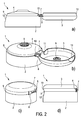
- Fig. 2 shows the hinged closure 1 according to the invention also a) in a side view in the manufacturing state (fully open) and b) in a perspective view in the manufacturing state and additionally c) in a perspective view obliquely from behind in the closed state and d) in a side view in the closed state.
- Fig. 2 is the axis of rotation of the hinge 7 relative to the parting plane 9 upwards, ie in the direction of the removal opening 5, offset.
- the projections 10 and 11 have a mutually complementary shape, so that in the closed state of the flap closure 1 on the one hand, the closure base 2 and the hinged lid 3 do not collide with each other and on the other hand between the closure base 2 and the hinged lid 3 results in a closed circumferential contact line without joints.
Landscapes
- Engineering & Computer Science (AREA)
- Mechanical Engineering (AREA)
- Manufacturing & Machinery (AREA)
- Closures For Containers (AREA)
Abstract
Description
- Die Erfindung betrifft einen Klappverschluss für einen Behälter, insbesondere für flüssige, pastöse oder pulverförmige Produkte, vorzugsweise Getränke, Chemikalien, Medikamente, Reinigungsmittel oder Ähnliches. Die vorliegende Anmeldung nimmt die Priorität der am 26. Mai 2015 angemeldeten deutschen Gebrauchsmusteranmeldung
DE 20 2015 003 783 in Anspruch und deren gesamter Inhalt wird durch Bezugnahme in die vorliegenden Anmeldung aufgenommen. Der Klappverschluss weist ein Verschlussunterteil und einen Klappdeckel auf, welche durch ein Scharnier drehbar verbunden sind. - Der Klappverschluss wird im Folgenden der Einfachheit halber in einem Zustand beschrieben, in dem er - wenn nicht anders angegeben - geschlossen ist und in einer horizontalen Orientierung auf dem oberen Ende eines Behälters montiert ist, wodurch sich das Verschlussunterteil unterhalb des Klappdeckels befindet. Dies stellt jedoch keine Einschränkung dar.
- Weiterhin weisen das Verschlussunterteil einen nach oben hervorstehenden Entnahmedom mit einer Entnahmeöffnung für das Produkt und der Klappdeckel einen nach unten hervorstehenden Dichtzapfen auf, wobei der Dichtzapfen beim Schließen des Klappverschlusses in den Entnahmedom eindringt und diesen dichtend verschließt.
- Bei derartigen Klappverschlüssen tritt oft das Problem auf, dass der Dichtzapfen sich beim Schließen des Klappdeckels nur relativ schwer, d. h. mit einem größeren Kraftaufwand, in den Entnahmedom einführen lässt, wenn er den Entnahmedom im geschlossenen Zustand des Klappverschlusses hinreichend gut abdichten soll. Dies ist insbesondere dann problematisch, wenn der Klappverschluss durch Spritzgießen aus Kunststoff gefertigt wird und bereits unmittelbar nach dem Spritzgießvorgang noch im Spritzgießwerkzeug geschlossen werden soll.
- Der vorliegenden Erfindung liegt die Aufgabe zu Grunde, einen Klappverschluss der genannten Art zu schaffen, bei dem der Schließvorgang erleichtert ist.
- Die Aufgabe wird gelöst durch einen Klappverschluss gemäß Merkmal 1. Vorteilhafte Ausführungen der Erfindung sind in den Unteransprüchen enthalten.
- Die Erfindung geht aus von einem Klappverschluss für einen Behälter, insbesondere für flüssige, pastöse oder pulverförmige Produkte, mit einem Verschlussunterteil zur Montage auf einer Entnahmeöffnung des Behälters und mit einem im geschlossenen Zustand des Klappverschlusses das Verschlussunterteil zumindest teilweise überdeckenden Klappdeckel.
- Dabei weist das Verschlussunterteil auf seiner dem Behälter abgewandten Außenseite einen im geschlossenen Zustand des Klappverschlusses in Richtung des Klappdeckels hervorstehenden Entnahmedom mit einer Entnahmeöffnung und der Klappdeckel auf seiner inneren Deckelfläche einen im geschlossenen Zustand des Klappverschlusses in Richtung des Verschlussunterteils hervorstehenden Dichtzapfen auf.
- Weiterhin sind das Verschlussunterteil und der Klappdeckel mittels wenigstens eines Scharniers derart um eine Drehachse drehbar miteinander verbunden, dass beim Schließen des Klappverschlusses der Dichtzapfen des Klappdeckels in den Entnahmedom des Verschlussunterteils eindringt und die Entnahmeöffnung dichtend verschließt und dass sich das Verschlussunterteil und der Klappdeckel auf dem größten Teil ihres außerhalb des Bereichs des Scharniers gelegenen Umfangs im Wesentlichen in einer Trennebene berühren.
- Die Erfindung basiert auf der Erkenntnis, dass es für ein leichtes Einführen des Dichtzapfens in den Entnahmedom günstig ist, wenn der Dichtzapfen beim Schließen des Klappdeckels möglichst steil in den Entnahmedom eingeführt wird, d. h. wenn der Schließwinkel möglichst klein ist. Unter dem Schließwinkel wird hierbei der Winkel zwischen einer Mittelachse des Entnahmedoms und einer Mittelachse des Dichtzapfens zu dem Zeitpunkt verstanden, an dem sich der Entnahmedom und der Dichtzapfen beim Schließen des Klappverschlusses erstmals berühren.
- Ist der Schließwinkel dagegen relativ groß, so neigen der Dichtzapfen und der Entnahmedom dazu, sich beim Einführen des Dichtzapfens in den Entnahmedom zu verkanten, wodurch die Reibung zwischen Dichtzapfen und Entnahmedom steigt und/oder sich insbesondere der Dichtzapfen beim Einführen stärker verformt, wodurch die zum Einführen erforderliche Kraft größer wird.
- Die Erfindung sieht nun vor, dass die Drehachse des Scharniers gegenüber der Trennebene in Richtung des Klappdeckels hin versetzt ist.
- Hierdurch wird der Schließwinkel gegenüber einem herkömmlichen Klappverschluss, bei dem die Drehachse des Scharniers üblicherweise in der Trennebene verläuft, verringert und somit das Einführen des Dichtzapfens in den Entnahmedom erleichtert.
- In einer bevorzugten Ausführung der Erfindung ist das Scharnier ein Filmscharnier. Ein solches Scharnier lässt sich leicht herstellen, insbesondere einstückig mit dem Verschlussunterteil und/oder mit dem Klappdeckel durch Spritzgießen, und ist insbesondere im geschlossenen Zustand des Klappverschlusses nur wenig sichtbar.
- In einer weiteren bevorzugten Ausführung der Erfindung sind das Verschlussunterteil und der Klappdeckel ferner über wenigstens ein Spannband verbunden, und das wenigstens eine Spannband verdeckt im geschlossenen Zustand des Klappverschlusses wenigstens einen Übergangsbereich auf der äußeren Umfangsfläche des Klappverschlusses zwischen der Trennebene und einer in Umfangsrichtung gesehen äußeren Grenze des Scharniers.
- Ein solches Spannband wird vorzugsweise dazu eingesetzt, um den Klappverschluss mit einer Schnappfunktion auszustatten, d. h. dass der Klappdeckel beim Öffnen ab einem bestimmten Öffnungswinkel selbsttätig in eine geöffnete Stellung "aufschnappt" und/oder beim Schließen ab einem bestimmten Öffnungswinkel selbsttätig in die geschlossene oder eine nahezu geschlossene Stellung "zuschnappt". Das Spannband ist vorzugsweise in Umfangsrichtung des Klappverschlusses unmittelbar neben dem Scharnier angeordnet und verbindet den Klappdeckel mit dem Verschlussunterteil.
- Der Übergangsbereich resultiert aus dem Höhenunterschied zwischen der Trennebene und der Drehachse des Scharniers, welcher sich erfindungsgemäß ergibt, und ist optisch beispielsweise durch einen "Versprung" oder "Versatz" der äußeren Umfangslinie des Klappverschlusses im Bereich der Trennebene wahrnehmbar. Dass das Spannband den Übergangsbereich zwischen der Trennebene und dem erfindungsgemäß gegenüber der Trennebene in Richtung des Klappdeckels hin versetzten Scharnier verdeckt, verbessert den optischen Eindruck des Klappverschlusses insbesondere im geschlossenen Zustand.
- In einer bevorzugten Variante dieser Ausführung der Erfindung sind das Verschlussunterteil und der Klappdeckel über zwei Spannbänder verbunden, und jedes Spannband verdeckt im geschlossenen Zustand des Klappverschlusses einen Übergangsbereich. Vorzugsweise sind die beiden Spannbänder auf beiden Seiten des Scharniers unmittelbar neben dem Scharnier angeordnet. Durch die Überdeckung der beiden Übergangsbereiche lässt sich erreichen, dass sich der Klappverschluss im geschlossenen Zustand optisch nicht oder nur kaum von einem herkömmlichen Klappverschluss, bei dem die Drehachse des Scharniers in der Trennebene verläuft, zu unterscheiden ist.
- In einer weiteren bevorzugten Variante dieser Ausführung der Erfindung hat wenigstens ein Übergangsbereich in Umfangsrichtung gesehen die Form einer Stufe oder einer geraden oder gekrümmten Schräge. Die Form des Übergangsbereichs kann dabei je nach den konstruktiven und/oder gestalterischen Rahmenbedingungen für den Klappverschluss gewählt werden. So kann der Übergangsbereich bei einem Klappverschluss mit abgerundeten Außenkonturen vorzugsweise in Form einer gekrümmten Schräge, welche keine "Knicke" aufweist, gestaltet werden, um den optischen Gesamteindruck des Klappverschlusses, insbesondere im offenen Zustand, nur wenig zu stören.
- In einer weiteren bevorzugten Ausführung der Erfindung beträgt der Abstand von der Trennebene zum Mittelpunkt der Drehachse des Scharniers wenigstens 10 %, vorzugsweise wenigstens 20 %, weiter vorzugsweise wenigstens 25 % des Abstandes von der Trennebene zur Entnahmeöffnung. Durch eine geeignete Wahl dieses Abstandes können die Position der Drehachse des Scharniers und die anderen konstruktiven Parameter, welche insgesamt den Schließwinkel bestimmen, insbesondere der Durchmesser des Klappverschlusses und eine etwaige Exzentrizität der Entnahmeöffnung, aufeinander abgestimmt werden.
- Gegenstand der Erfindung ist weiterhin eine Spritzgießmaschine zur Herstellung eines erfindungsgemäßen Klappverschlusses, welche Mittel aufweist, um den Klappverschluss nach dem Spritzgießen und vor dem vollständigen Entnehmen aus dem Spritzgießwerkzeug zu schließen. Der Klappverschluss wird dabei vorzugsweise aus einem Kunststoffmaterial spritzgegossen.
- Vorzugsweise handelt es sich hierbei um eine Spritzgießmaschine, in welcher der erfindungsgemäße Klappverschluss einstückig spritzgegossen wird. Eine andere bevorzugte Herstellung sieht vor, dass der Klappdeckel an das Verschlussunterteil oder das Verschlussunterteil an den Klappdeckel angespritzt wird, wobei dasjenige Teil, an das das andere Teil angespritzt wird, vorher separat spritzgegossen wurde und wobei vorzugsweise eines der beiden Teile einstückig mit dem Scharnier spritzgegossen wird.
- Beim Schließen des Klappverschlusses befindet sich vorzugsweise das Verschlussunterteil noch in seiner Spritzgießform oder -formhälfte, während die Spritzgießform oder -formhälfte des Klappdeckels bereits entfernt wurde.
- Die Mittel zum Schließen des Klappverschlusses bestehen vorzugsweise aus einer mechanischen Einrichtung, welche durch einen Druck auf den Klappdeckel bewirken, dass dieser sich um die Drehachse des Scharniers in Richtung des Verschlussunterteils dreht und dadurch der Klappverschluss geschlossen wird.
- Dieser Vorgang kann jedoch auch mit vertauschten Rollen des Verschlussunterteils und des Klappdeckels ablaufen, d. h. das Verschlussunterteil wird durch die Mittel zum Schließen in Richtung des Klappdeckels gedreht und dadurch der Klappverschluss geschlossen.
- Weitere Ausgestaltungen und Vorteile der Erfindung gehen aus der folgenden Beschreibung in Verbindung mit den Zeichnungen hervor. Dabei zeigen:
- Fig. 1:
- einen Klappverschluss aus dem Stand der Technik im geöffneten Zustand in einer Seitenansicht, einer perspektivischen Ansicht und einer Schnittdarstellung;
- Fig. 2:
- einen erfindungsgemäßen Klappverschluss im geöffneten Zustand in einer Seitenansicht und in einer perspektivischen Ansicht sowie im geschlossenen Zustand in einer perspektivischen Ansicht und einer Seitenansicht.
-
Fig. 1 zeigt einen Klappverschluss 1 aus dem Stand der Technik, und zwar a) in einer Seitenansicht im Herstellungszustand (vollständig geöffnet), b) in einer perspektivischen Ansicht im Herstellungszustand und c) in einem vertikalen Schnitt im nahezu geschlossenen Zustand. - Der Klappverschluss 1 weist ein Verschlussunterteil 2 und einen Klappdeckel 3 auf, welche durch ein Scharnier 7, vorzugsweise ein Filmscharnier, miteinander verbunden sind, wobei das Scharnier 7 durch zwei in Umfangsrichtung gesehen links und rechts des Scharniers 7 angeordnete Spannbänder 8 mit einer Schnappfunktion ausgestattet ist.
- Die Drehachse des Scharniers 7 liegt in der Trennebene 9, in welcher sich das Verschlussunterteil 2 und der Klappdeckel 3 im geschlossenen Zustand des Klappverschlusses 1 berühren. Insbesondere in der Seitenansicht in
Fig. 1 a) ist die Trennebene 9 als waagerechte Linie gut zu erkennen. - Weiterhin weist das Verschlussunterteil 2 eine Griffmulde 12 und der Klappdeckel 3 eine Griffmulde 13 auf, in welche im geschlossenen Zustand des Klappverschlusses 1 ein Finger, vorzugsweise ein Daumen, gelegt werden kann, wodurch das Hochdrücken des Klappdeckels 3 und damit das Öffnen des Klappverschlusses 1 erleichtert wird.
- Das Verschlussunterteil 2 weist weiterhin an seiner Oberseite einen Entnahmedom 4 auf, welcher sich über die Trennebene erhebt und an dessen oberem Ende in der Mitte sich die Entnahmeöffnung 5 befindet. Der Klappdeckel 3 weist an seiner Innenseite einen Dichtzapfen 6 auf, welcher beim Schließen des Klappdeckels 3 in die Entnahmeöffnung 5 eindringt und diese dichtend verschließt.
- Der Klappverschluss 1 ist dafür vorgesehen, mittels Aufprellelementen 14 auf einen entsprechenden Wulst auf dem Hals eines Behälters (nicht dargestellt) aufgeprellt zu werden.
- Beim Schließen des Klappdeckels 3 haben die Mittelachse der Entnahmeöffnung 5, welche vertikal verläuft, und die Mittelachse des Dichtzapfens 6 zu dem Zeitpunkt, an dem der Dichtzapfen 6 den Entnahmedom 4 erstmals berührt, einen relativ großen Winkel zueinander.
- Der Zustand des Klappverschlusses 1 zu diesem Zeitpunkt ist in
Fig. 1 c) dargestellt. Man erkennt in der Schnittdarstellung, dass der rechte Rand des Dichtzapfens 6 bereits den Entnahmedom 4 am rechten Rand der Entnahmeöffnung 5 berührt, während der linke Rand des Dichtzapfens 6 den Entnahmedom 4 am linken Rand der Entnahmeöffnung 5 noch nicht berührt. Durch den genannten, relativ großen Winkel kann sich der Dichtzapfen 6 in der Entnahmeöffnung 5 verkanten, was das Schließen des Klappdeckels 3 erschwert. -
Fig. 2 zeigt den erfindungsgemäßen Klappverschluss 1 ebenfalls a) in einer Seitenansicht im Herstellungszustand (vollständig geöffnet) und b) in einer perspektivischen Ansicht im Herstellungszustand sowie zusätzlich c) in einer perspektivischen Ansicht von schräg hinten im geschlossenen Zustand und d) in einer Seitenansicht im geschlossenen Zustand. - Soweit die Elemente des erfindungsgemäßen Klappverschlusses gemäß
Fig. 2 mit denjenigen des Klappverschlusses aus dem Stand der Technik gemäßFig. 1 übereinstimmen, wurden auch die gleichen Bezugszeichen verwendet. Die gemeinsamen Elemente der inFig. 1 und2 dargestellten Klappverschlüsse werden hier nicht noch einmal beschrieben. - In dem erfindungsgemäßen Klappverschluss 1 gemäß
Fig. 2 ist die Drehachse des Scharniers 7 gegenüber der Trennebene 9 nach oben hin, d. h. in Richtung der Entnahmeöffnung 5, versetzt. Dadurch wird der Winkel zwischen der vertikalen Mittelachse der Entnahmeöffnung 5 und der Mittelachse des Dichtzapfens 6 zum Zeitpunkt der ersten Berührung zwischen Dichtzapfen 6 und Entnahmedom 4 beim Schließen des Klappdeckels 3 verringert und somit das Schließen erleichtert. - Durch das Versetzen der Drehachse des Scharniers 7 aus der Trennebene 9 nach oben hin entsteht zwischen der Trennebene 9 und dem Scharnier 7 auf dem Umfang des Verschlussunterteils 2 auf beiden Seiten des Scharniers 7 jeweils ein vertikaler Versprung 10. Entsprechend entsteht an dem Rand des Klappdeckels 3, an dem das Scharnier befestigt ist, auf beiden Seiten des Scharniers 7 jeweils ein (im geschlossenen Zustand des Klappverschlusses 1) vertikaler Versprung 11. Jeweils ein Versprung 10 am Verschlussunterteil 2 und ein Versprung 11 am Klappdeckel 3 ist besonders in
Fig. 2 b) gut zu erkennen. - Vorzugsweise haben die Versprünge 10 und 11 eine zueinander komplementäre Form, damit im geschlossenen Zustand der Klappverschlusses 1 einerseits das Verschlussunterteil 2 und der Klappdeckel 3 nicht miteinander kollidieren und sich andererseits zwischen dem Verschlussunterteil 2 und dem Klappdeckel 3 eine geschlossene umlaufende Berührungslinie ohne Fugen ergibt.
- In
Fig. 2 c) ist zu sehen, dass die Versprünge 10 und 11 am Verschlussunterteil 2 bzw. am Klappdeckel 3 im geschlossenen Zustand des Klappverschlusses 1 praktisch vollständig von den Spannbändern 8 verdeckt werden und somit für den Benutzer nahezu unsichtbar sind. Der einzige im geschlossenen Zustand des erfindungsgemäßen Klappverschlusses 1 sichtbare Unterschied gegenüber einem Klappverschluss aus dem Stand der Technik besteht darin, dass die Spannbänder 8 und das Scharnier 7 in vertikaler Richtung nicht mehr symmetrisch zur Trennebene 9 angeordnet sind, was jedoch den optischen Eindruck des Klappverschlusses 1 höchstens geringfügig beeinträchtigt. -
- 1
- Klappverschluss
- 2
- Verschlussunterteil
- 3
- Klappdeckel
- 4
- Entnahmedom
- 5
- Entnahmeöffnung
- 6
- Dichtzapfen
- 7
- Scharnier
- 8
- Spannband
- 9
- Trennebene
- 10
- Versprung am Verschlussunterteil
- 11
- Versprung am Klappdeckel
- 12
- Griffmulde am Verschlussunterteil
- 13
- Griffmulde am Klappdeckel
- 14
- Aufprellelement
Claims (13)
- Klappverschluss (1) für einen Behälter, insbesondere für flüssige, pastöse oder pulverförmige Produkte, mit einem Verschlussunterteil (2) zur Montage auf einer Entnahmeöffnung des Behälters und mit einem im geschlossenen Zustand des Klappverschlusses (1) das Verschlussunterteil (2) zumindest teilweise überdeckenden Klappdeckel (3),
wobei das Verschlussunterteil (2) auf seiner dem Behälter abgewandten Außenseite einen im geschlossenen Zustand des Klappverschlusses (1) in Richtung des Klappdeckels (3) hervorstehenden Entnahmedom (4) mit einer Entnahmeöffnung (5) und der Klappdeckel (3) auf seiner inneren Deckelfläche einen im geschlossenen Zustand des Klappverschlusses (1) in Richtung des Verschlussunterteils (2) hervorstehenden Dichtzapfen (6) aufweist,
wobei das Verschlussunterteil (2) und der Klappdeckel (3) mittels wenigstens eines Scharniers (7) derart um eine Drehachse drehbar miteinander verbunden sind, dass beim Schließen des Klappverschlusses (1) der Dichtzapfen (6) des Klappdeckels (3) in den Entnahmedom (4) des Verschlussunterteils (2) eindringt und die Entnahmeöffnung (5) dichtend verschließt und sich das Verschlussunterteil (2) und der Klappdeckel (3) auf dem größten Teil ihres außerhalb des Bereichs des Scharniers (7) gelegenen Umfangs im Wesentlichen in einer Trennebene (9) berühren,
dadurch gekennzeichnet, dass
die Drehachse des Scharniers (7) gegenüber der Trennebene (9) in Richtung des Klappdeckels (3) hin versetzt ist. - Klappverschluss (1) gemäß Anspruch 1, dadurch gekennzeichnet, dass das Scharnier (7) ein Filmscharnier ist.
- Klappverschluss (1) gemäß einem der vorhergehenden Ansprüche, dadurch gekennzeichnet, dass das Verschlussunterteil (2) und der Klappdeckel (3) ferner über wenigstens ein Spannband (8) verbunden sind und das wenigstens eine Spannband (8) im geschlossenen Zustand des Klappverschlusses (1) wenigstens einen Übergangsbereich (10, 11) auf der äußeren Umfangsfläche des Klappverschlusses (1) zwischen der Trennebene (9) und einer in Umfangsrichtung gesehen äußeren Grenze des Scharniers (7) verdeckt.
- Klappverschluss (1) gemäß Anspruch 3, dadurch gekennzeichnet, dass das Verschlussunterteil (2) und der Klappdeckel (3) über zwei Spannbänder (8) verbunden sind und jedes Spannband (8) im geschlossenen Zustand des Klappverschlusses (1) einen Übergangsbereich (10, 11) verdeckt.
- Klappverschluss (1) gemäß Anspruch 3 oder 4, dadurch gekennzeichnet, dass wenigstens ein Übergangsbereich (10, 11) in Umfangsrichtung gesehen die Form einer Stufe oder einer geraden oder gekrümmten Schräge hat.
- Klappverschluss (1) gemäß einem der vorhergehenden Ansprüche, dadurch gekennzeichnet, dass der Abstand von der Trennebene (9) zum Mittelpunkt der Drehachse des Scharniers (7) wenigstens 10 %, vorzugsweise wenigstens 20 %, weiter vorzugsweise wenigstens 25 % des Abstandes von der Trennebene (9) zur Entnahmeöffnung (5) beträgt.
- Spritzgießmaschine zur Herstellung eines Klappverschlusses (1) gemäß einem der vorhergehenden Ansprüche, dadurch gekennzeichnet, dass die Spritzgießmaschine Mittel aufweist, um den Klappverschluss (1) nach dem Spritzgießen und vor dem vollständigen Entnehmen aus dem Spritzgießwerkzeug zu schließen.
- Verfahren zur Herstellung eines Klappverschlusses (1) gemäß einem der Ansprüche 1 bis 6, dadurch gekennzeichnet, dass das Verfahren ein Spritzgießen aufweist.
- Verfahren zur Herstellung eines Klappverschlusses (1) gemäß Anspruch 8, dadurch gekennzeichnet, dass der Klappverschluss (1) nach dem Spritzgießen und vor dem vollständigen Entnehmen geschlossen wird.
- Verfahren zur Herstellung eines Klappverschlusses (1) gemäß Anspruch 8 oder 9, dadurch gekennzeichnet, dass das Verschlussunterteil (2) sich noch in seiner Spritzgießform oder in seiner Spritzgießformhälfte befindet, während die Spritzgießform oder Spritzgießformhälfte des Klappdeckels (3) bereits entfernt worden ist.
- Verfahren zur Herstellung eines Klappverschlusses (1) gemäß einem der Ansprüche 8 bis 10, dadurch gekennzeichnet, dass der Klappdeckel (3) an das Verschlussunterteil (2) oder dass das Verschlussunterteil (2) an den Klappdeckel (3) angespritzt wird.
- Verfahren zur Herstellung eines Klappverschlusses (1) gemäß Anspruch 11 dadurch gekennzeichnet, dass das dasjenige Teil, an das das andere Teil angespritzt wird, vorher separat spritzgegossen wurde, und dass insbesondere eines der beiden Teile einstückig mit dem Scharnier (7) spritzgegossen wird.
- Verfahren zur Herstellung eines Klappverschlusses (1) gemäß einem der Ansprüche 8 bis 12, dadurch gekennzeichnet, dass der Klappverschluss (1) aus einem Kunststoffmaterial spritzgegossen wird.
Priority Applications (1)
| Application Number | Priority Date | Filing Date | Title |
|---|---|---|---|
| PL16170959T PL3098048T3 (pl) | 2015-05-26 | 2016-05-24 | Zamknięcie klapkowe |
Applications Claiming Priority (1)
| Application Number | Priority Date | Filing Date | Title |
|---|---|---|---|
| DE202015003783.6U DE202015003783U1 (de) | 2015-05-26 | 2015-05-26 | Klappverschluss |
Publications (2)
| Publication Number | Publication Date |
|---|---|
| EP3098048A1 true EP3098048A1 (de) | 2016-11-30 |
| EP3098048B1 EP3098048B1 (de) | 2018-02-28 |
Family
ID=53782840
Family Applications (1)
| Application Number | Title | Priority Date | Filing Date |
|---|---|---|---|
| EP16170959.7A Active EP3098048B1 (de) | 2015-05-26 | 2016-05-24 | Klappverschluss |
Country Status (4)
| Country | Link |
|---|---|
| EP (1) | EP3098048B1 (de) |
| DE (1) | DE202015003783U1 (de) |
| ES (1) | ES2671508T3 (de) |
| PL (1) | PL3098048T3 (de) |
Cited By (3)
| Publication number | Priority date | Publication date | Assignee | Title |
|---|---|---|---|---|
| CN110015498A (zh) * | 2019-05-17 | 2019-07-16 | 卓高泰(广州)材料科技有限公司 | 一种易于倒出及回流的翻盖和瓶子 |
| US11040806B2 (en) | 2017-12-15 | 2021-06-22 | Husky Injection Molding Systems Ltd. | Closure cap for a container |
| JP2022173727A (ja) * | 2021-05-10 | 2022-11-22 | 凸版印刷株式会社 | 射出成形体の製造方法 |
Families Citing this family (2)
| Publication number | Priority date | Publication date | Assignee | Title |
|---|---|---|---|---|
| DE202015003783U1 (de) | 2015-05-26 | 2015-07-20 | Weener Plastik Gmbh | Klappverschluss |
| CN105270722B (zh) * | 2015-11-05 | 2017-07-04 | 张卫 | 开关式酒瓶盖 |
Citations (8)
| Publication number | Priority date | Publication date | Assignee | Title |
|---|---|---|---|---|
| US4220248A (en) * | 1978-10-31 | 1980-09-02 | Polytop Corporation | Closure with hinged lid and cam and spring elements holding lid open or closed |
| FR2633590A1 (fr) * | 1988-07-01 | 1990-01-05 | Astra Plastique | Bouchon-verseur en matiere synthetique a capuchon articule |
| DE4219598A1 (de) * | 1992-06-16 | 1993-12-23 | Createchnic Ag Dietlikon | Zweikammerflasche mit Kunststoffverschluß |
| DE20304496U1 (de) * | 2003-03-20 | 2003-06-18 | Kunststoffwerk Kremsmünster Ges.m.b.H & Co.KG, Wien | Klappverschluss |
| WO2006045087A2 (en) * | 2004-10-20 | 2006-04-27 | Csp Technologies, Inc. | Re-sealable moisture tight containers for strips and the like having alternative sealing mechanisms |
| DE202009000138U1 (de) * | 2009-01-05 | 2009-03-19 | Weener Plastik Ag | Klappverschluss |
| JP2013184727A (ja) * | 2012-03-08 | 2013-09-19 | Kureha Corp | 植物由来のポリオレフィンを含有するトグル構造を備えるキャップ |
| DE202015003783U1 (de) | 2015-05-26 | 2015-07-20 | Weener Plastik Gmbh | Klappverschluss |
-
2015
- 2015-05-26 DE DE202015003783.6U patent/DE202015003783U1/de not_active Expired - Lifetime
-
2016
- 2016-05-24 EP EP16170959.7A patent/EP3098048B1/de active Active
- 2016-05-24 PL PL16170959T patent/PL3098048T3/pl unknown
- 2016-05-24 ES ES16170959.7T patent/ES2671508T3/es active Active
Patent Citations (9)
| Publication number | Priority date | Publication date | Assignee | Title |
|---|---|---|---|---|
| US4220248A (en) * | 1978-10-31 | 1980-09-02 | Polytop Corporation | Closure with hinged lid and cam and spring elements holding lid open or closed |
| CA1121310A (en) * | 1978-10-31 | 1982-04-06 | Polytop Corporation | Closure with hinged lid and cam and spring elements holding lid open or closed |
| FR2633590A1 (fr) * | 1988-07-01 | 1990-01-05 | Astra Plastique | Bouchon-verseur en matiere synthetique a capuchon articule |
| DE4219598A1 (de) * | 1992-06-16 | 1993-12-23 | Createchnic Ag Dietlikon | Zweikammerflasche mit Kunststoffverschluß |
| DE20304496U1 (de) * | 2003-03-20 | 2003-06-18 | Kunststoffwerk Kremsmünster Ges.m.b.H & Co.KG, Wien | Klappverschluss |
| WO2006045087A2 (en) * | 2004-10-20 | 2006-04-27 | Csp Technologies, Inc. | Re-sealable moisture tight containers for strips and the like having alternative sealing mechanisms |
| DE202009000138U1 (de) * | 2009-01-05 | 2009-03-19 | Weener Plastik Ag | Klappverschluss |
| JP2013184727A (ja) * | 2012-03-08 | 2013-09-19 | Kureha Corp | 植物由来のポリオレフィンを含有するトグル構造を備えるキャップ |
| DE202015003783U1 (de) | 2015-05-26 | 2015-07-20 | Weener Plastik Gmbh | Klappverschluss |
Cited By (4)
| Publication number | Priority date | Publication date | Assignee | Title |
|---|---|---|---|---|
| US11040806B2 (en) | 2017-12-15 | 2021-06-22 | Husky Injection Molding Systems Ltd. | Closure cap for a container |
| CN110015498A (zh) * | 2019-05-17 | 2019-07-16 | 卓高泰(广州)材料科技有限公司 | 一种易于倒出及回流的翻盖和瓶子 |
| CN110015498B (zh) * | 2019-05-17 | 2024-11-05 | 卓高泰(广州)材料科技有限公司 | 一种易于倒出及回流的翻盖和瓶子 |
| JP2022173727A (ja) * | 2021-05-10 | 2022-11-22 | 凸版印刷株式会社 | 射出成形体の製造方法 |
Also Published As
| Publication number | Publication date |
|---|---|
| PL3098048T3 (pl) | 2018-08-31 |
| DE202015003783U1 (de) | 2015-07-20 |
| ES2671508T3 (es) | 2018-06-06 |
| EP3098048B1 (de) | 2018-02-28 |
Similar Documents
| Publication | Publication Date | Title |
|---|---|---|
| DE69300251T2 (de) | Verpackungsvorrichtung, insbesondere für kosmetische Produkte. | |
| DE69508462T2 (de) | Originalitätsverschluss | |
| EP2670683B1 (de) | Klappdeckelverschluss mit betätigungsteil und originalitätssicherung | |
| EP3098048B1 (de) | Klappverschluss | |
| WO2017076398A1 (de) | Schnappdeckel in mehrkomponenten-spritzgusstechnik | |
| EP3526131B1 (de) | Kunststoffverschluss mit einem unversehrtheitsgarantieelement | |
| EP0986501B1 (de) | Einteiliger kunststoffverschluss | |
| DE10246086B4 (de) | Behälter | |
| DE4421766A1 (de) | Vorrichtung mit Drückelement zum Verschließen einer seitlichen Auslaßöffnung durch axiales Verschieben | |
| EP1194342B1 (de) | Zweiteiliger schnappscharnierverschluss aus kunststoff | |
| DE69903580T2 (de) | Originalitätsverschluss | |
| WO1994022732A1 (de) | Kunststoffverschluss | |
| EP3458376A1 (de) | Trinkbecherdeckel | |
| WO2019096795A1 (de) | Kunststoffverschlussteil mit abtrennbarer membran | |
| DE3410420A1 (de) | Behaelter | |
| EP3807161B1 (de) | Behälter mit einem bistabilen deckel | |
| DE102009010681B3 (de) | Deckelanordnung mit Originalitätssiegel | |
| DE102005059675B4 (de) | Verschluss und Verfahren zu dessen Herstellung | |
| DE102020132335A1 (de) | Papier- oder Kartonverpackung | |
| DE69725690T2 (de) | Verschlusskappe für einen mit einem Befestigungsflansch versehenen Behälter | |
| EP0868360A1 (de) | Verschlusskappe | |
| DE2904290A1 (de) | Verschlussanordnung | |
| DE2024385C3 (de) | Sicherheitsverschluß für einen Behalter | |
| CH674831A5 (en) | Hinged plastic closure cap for bottles - has integrally moulded cap, guarantee band and a lower part | |
| EP3145830B1 (de) | Behälterverschluss |
Legal Events
| Date | Code | Title | Description |
|---|---|---|---|
| PUAI | Public reference made under article 153(3) epc to a published international application that has entered the european phase |
Free format text: ORIGINAL CODE: 0009012 |
|
| AK | Designated contracting states |
Kind code of ref document: A1 Designated state(s): AL AT BE BG CH CY CZ DE DK EE ES FI FR GB GR HR HU IE IS IT LI LT LU LV MC MK MT NL NO PL PT RO RS SE SI SK SM TR |
|
| AX | Request for extension of the european patent |
Extension state: BA ME |
|
| RIN1 | Information on inventor provided before grant (corrected) |
Inventor name: SCHIPPER, MICHAEL |
|
| 17P | Request for examination filed |
Effective date: 20170327 |
|
| RBV | Designated contracting states (corrected) |
Designated state(s): AL AT BE BG CH CY CZ DE DK EE ES FI FR GB GR HR HU IE IS IT LI LT LU LV MC MK MT NL NO PL PT RO RS SE SI SK SM TR |
|
| GRAJ | Information related to disapproval of communication of intention to grant by the applicant or resumption of examination proceedings by the epo deleted |
Free format text: ORIGINAL CODE: EPIDOSDIGR1 |
|
| GRAP | Despatch of communication of intention to grant a patent |
Free format text: ORIGINAL CODE: EPIDOSNIGR1 |
|
| RIC1 | Information provided on ipc code assigned before grant |
Ipc: B29C 45/00 20060101AFI20171010BHEP Ipc: B65D 47/08 20060101ALI20171010BHEP |
|
| INTG | Intention to grant announced |
Effective date: 20171031 |
|
| RIN1 | Information on inventor provided before grant (corrected) |
Inventor name: SCHIPPER, MICHAEL |
|
| GRAS | Grant fee paid |
Free format text: ORIGINAL CODE: EPIDOSNIGR3 |
|
| GRAA | (expected) grant |
Free format text: ORIGINAL CODE: 0009210 |
|
| AK | Designated contracting states |
Kind code of ref document: B1 Designated state(s): AL AT BE BG CH CY CZ DE DK EE ES FI FR GB GR HR HU IE IS IT LI LT LU LV MC MK MT NL NO PL PT RO RS SE SI SK SM TR |
|
| REG | Reference to a national code |
Ref country code: GB Ref legal event code: FG4D Free format text: NOT ENGLISH Ref country code: CH Ref legal event code: EP |
|
| REG | Reference to a national code |
Ref country code: AT Ref legal event code: REF Ref document number: 973622 Country of ref document: AT Kind code of ref document: T Effective date: 20180315 |
|
| REG | Reference to a national code |
Ref country code: IE Ref legal event code: FG4D Free format text: LANGUAGE OF EP DOCUMENT: GERMAN |
|
| REG | Reference to a national code |
Ref country code: DE Ref legal event code: R096 Ref document number: 502016000605 Country of ref document: DE |
|
| REG | Reference to a national code |
Ref country code: NL Ref legal event code: FP |
|
| REG | Reference to a national code |
Ref country code: FR Ref legal event code: PLFP Year of fee payment: 3 |
|
| REG | Reference to a national code |
Ref country code: ES Ref legal event code: FG2A Ref document number: 2671508 Country of ref document: ES Kind code of ref document: T3 Effective date: 20180606 |
|
| REG | Reference to a national code |
Ref country code: LT Ref legal event code: MG4D |
|
| PG25 | Lapsed in a contracting state [announced via postgrant information from national office to epo] |
Ref country code: FI Free format text: LAPSE BECAUSE OF FAILURE TO SUBMIT A TRANSLATION OF THE DESCRIPTION OR TO PAY THE FEE WITHIN THE PRESCRIBED TIME-LIMIT Effective date: 20180228 Ref country code: NO Free format text: LAPSE BECAUSE OF FAILURE TO SUBMIT A TRANSLATION OF THE DESCRIPTION OR TO PAY THE FEE WITHIN THE PRESCRIBED TIME-LIMIT Effective date: 20180528 Ref country code: CY Free format text: LAPSE BECAUSE OF FAILURE TO SUBMIT A TRANSLATION OF THE DESCRIPTION OR TO PAY THE FEE WITHIN THE PRESCRIBED TIME-LIMIT Effective date: 20180228 Ref country code: LT Free format text: LAPSE BECAUSE OF FAILURE TO SUBMIT A TRANSLATION OF THE DESCRIPTION OR TO PAY THE FEE WITHIN THE PRESCRIBED TIME-LIMIT Effective date: 20180228 Ref country code: HR Free format text: LAPSE BECAUSE OF FAILURE TO SUBMIT A TRANSLATION OF THE DESCRIPTION OR TO PAY THE FEE WITHIN THE PRESCRIBED TIME-LIMIT Effective date: 20180228 |
|
| PG25 | Lapsed in a contracting state [announced via postgrant information from national office to epo] |
Ref country code: GR Free format text: LAPSE BECAUSE OF FAILURE TO SUBMIT A TRANSLATION OF THE DESCRIPTION OR TO PAY THE FEE WITHIN THE PRESCRIBED TIME-LIMIT Effective date: 20180529 Ref country code: BG Free format text: LAPSE BECAUSE OF FAILURE TO SUBMIT A TRANSLATION OF THE DESCRIPTION OR TO PAY THE FEE WITHIN THE PRESCRIBED TIME-LIMIT Effective date: 20180528 Ref country code: RS Free format text: LAPSE BECAUSE OF FAILURE TO SUBMIT A TRANSLATION OF THE DESCRIPTION OR TO PAY THE FEE WITHIN THE PRESCRIBED TIME-LIMIT Effective date: 20180228 Ref country code: LV Free format text: LAPSE BECAUSE OF FAILURE TO SUBMIT A TRANSLATION OF THE DESCRIPTION OR TO PAY THE FEE WITHIN THE PRESCRIBED TIME-LIMIT Effective date: 20180228 Ref country code: SE Free format text: LAPSE BECAUSE OF FAILURE TO SUBMIT A TRANSLATION OF THE DESCRIPTION OR TO PAY THE FEE WITHIN THE PRESCRIBED TIME-LIMIT Effective date: 20180228 |
|
| PG25 | Lapsed in a contracting state [announced via postgrant information from national office to epo] |
Ref country code: MT Free format text: LAPSE BECAUSE OF FAILURE TO SUBMIT A TRANSLATION OF THE DESCRIPTION OR TO PAY THE FEE WITHIN THE PRESCRIBED TIME-LIMIT Effective date: 20180228 |
|
| PG25 | Lapsed in a contracting state [announced via postgrant information from national office to epo] |
Ref country code: RO Free format text: LAPSE BECAUSE OF FAILURE TO SUBMIT A TRANSLATION OF THE DESCRIPTION OR TO PAY THE FEE WITHIN THE PRESCRIBED TIME-LIMIT Effective date: 20180228 Ref country code: AL Free format text: LAPSE BECAUSE OF FAILURE TO SUBMIT A TRANSLATION OF THE DESCRIPTION OR TO PAY THE FEE WITHIN THE PRESCRIBED TIME-LIMIT Effective date: 20180228 Ref country code: EE Free format text: LAPSE BECAUSE OF FAILURE TO SUBMIT A TRANSLATION OF THE DESCRIPTION OR TO PAY THE FEE WITHIN THE PRESCRIBED TIME-LIMIT Effective date: 20180228 |
|
| REG | Reference to a national code |
Ref country code: DE Ref legal event code: R097 Ref document number: 502016000605 Country of ref document: DE |
|
| PG25 | Lapsed in a contracting state [announced via postgrant information from national office to epo] |
Ref country code: CZ Free format text: LAPSE BECAUSE OF FAILURE TO SUBMIT A TRANSLATION OF THE DESCRIPTION OR TO PAY THE FEE WITHIN THE PRESCRIBED TIME-LIMIT Effective date: 20180228 Ref country code: SM Free format text: LAPSE BECAUSE OF FAILURE TO SUBMIT A TRANSLATION OF THE DESCRIPTION OR TO PAY THE FEE WITHIN THE PRESCRIBED TIME-LIMIT Effective date: 20180228 Ref country code: DK Free format text: LAPSE BECAUSE OF FAILURE TO SUBMIT A TRANSLATION OF THE DESCRIPTION OR TO PAY THE FEE WITHIN THE PRESCRIBED TIME-LIMIT Effective date: 20180228 Ref country code: SK Free format text: LAPSE BECAUSE OF FAILURE TO SUBMIT A TRANSLATION OF THE DESCRIPTION OR TO PAY THE FEE WITHIN THE PRESCRIBED TIME-LIMIT Effective date: 20180228 |
|
| PLBE | No opposition filed within time limit |
Free format text: ORIGINAL CODE: 0009261 |
|
| STAA | Information on the status of an ep patent application or granted ep patent |
Free format text: STATUS: NO OPPOSITION FILED WITHIN TIME LIMIT |
|
| PG25 | Lapsed in a contracting state [announced via postgrant information from national office to epo] |
Ref country code: MC Free format text: LAPSE BECAUSE OF FAILURE TO SUBMIT A TRANSLATION OF THE DESCRIPTION OR TO PAY THE FEE WITHIN THE PRESCRIBED TIME-LIMIT Effective date: 20180228 |
|
| 26N | No opposition filed |
Effective date: 20181129 |
|
| REG | Reference to a national code |
Ref country code: IE Ref legal event code: MM4A |
|
| PG25 | Lapsed in a contracting state [announced via postgrant information from national office to epo] |
Ref country code: SI Free format text: LAPSE BECAUSE OF FAILURE TO SUBMIT A TRANSLATION OF THE DESCRIPTION OR TO PAY THE FEE WITHIN THE PRESCRIBED TIME-LIMIT Effective date: 20180228 |
|
| PG25 | Lapsed in a contracting state [announced via postgrant information from national office to epo] |
Ref country code: IE Free format text: LAPSE BECAUSE OF NON-PAYMENT OF DUE FEES Effective date: 20180524 |
|
| REG | Reference to a national code |
Ref country code: CH Ref legal event code: PL |
|
| PG25 | Lapsed in a contracting state [announced via postgrant information from national office to epo] |
Ref country code: LI Free format text: LAPSE BECAUSE OF NON-PAYMENT OF DUE FEES Effective date: 20190531 Ref country code: CH Free format text: LAPSE BECAUSE OF NON-PAYMENT OF DUE FEES Effective date: 20190531 |
|
| PG25 | Lapsed in a contracting state [announced via postgrant information from national office to epo] |
Ref country code: PT Free format text: LAPSE BECAUSE OF FAILURE TO SUBMIT A TRANSLATION OF THE DESCRIPTION OR TO PAY THE FEE WITHIN THE PRESCRIBED TIME-LIMIT Effective date: 20180228 |
|
| PG25 | Lapsed in a contracting state [announced via postgrant information from national office to epo] |
Ref country code: HU Free format text: LAPSE BECAUSE OF FAILURE TO SUBMIT A TRANSLATION OF THE DESCRIPTION OR TO PAY THE FEE WITHIN THE PRESCRIBED TIME-LIMIT; INVALID AB INITIO Effective date: 20160524 Ref country code: MK Free format text: LAPSE BECAUSE OF NON-PAYMENT OF DUE FEES Effective date: 20180228 |
|
| PG25 | Lapsed in a contracting state [announced via postgrant information from national office to epo] |
Ref country code: IS Free format text: LAPSE BECAUSE OF FAILURE TO SUBMIT A TRANSLATION OF THE DESCRIPTION OR TO PAY THE FEE WITHIN THE PRESCRIBED TIME-LIMIT Effective date: 20180628 |
|
| REG | Reference to a national code |
Ref country code: AT Ref legal event code: MM01 Ref document number: 973622 Country of ref document: AT Kind code of ref document: T Effective date: 20210524 |
|
| PG25 | Lapsed in a contracting state [announced via postgrant information from national office to epo] |
Ref country code: AT Free format text: LAPSE BECAUSE OF NON-PAYMENT OF DUE FEES Effective date: 20210524 |
|
| P01 | Opt-out of the competence of the unified patent court (upc) registered |
Effective date: 20230505 |
|
| PGFP | Annual fee paid to national office [announced via postgrant information from national office to epo] |
Ref country code: TR Payment date: 20230522 Year of fee payment: 8 |
|
| PGFP | Annual fee paid to national office [announced via postgrant information from national office to epo] |
Ref country code: NL Payment date: 20250522 Year of fee payment: 10 |
|
| PGFP | Annual fee paid to national office [announced via postgrant information from national office to epo] |
Ref country code: PL Payment date: 20250516 Year of fee payment: 10 Ref country code: DE Payment date: 20250519 Year of fee payment: 10 |
|
| PGFP | Annual fee paid to national office [announced via postgrant information from national office to epo] |
Ref country code: GB Payment date: 20250522 Year of fee payment: 10 Ref country code: ES Payment date: 20250616 Year of fee payment: 10 |
|
| PGFP | Annual fee paid to national office [announced via postgrant information from national office to epo] |
Ref country code: LU Payment date: 20250520 Year of fee payment: 10 Ref country code: BE Payment date: 20250520 Year of fee payment: 10 Ref country code: IT Payment date: 20250530 Year of fee payment: 10 |
|
| PGFP | Annual fee paid to national office [announced via postgrant information from national office to epo] |
Ref country code: FR Payment date: 20250521 Year of fee payment: 10 |