EP3095717A1 - Schalenverschliessmaschine - Google Patents
Schalenverschliessmaschine Download PDFInfo
- Publication number
- EP3095717A1 EP3095717A1 EP15168593.0A EP15168593A EP3095717A1 EP 3095717 A1 EP3095717 A1 EP 3095717A1 EP 15168593 A EP15168593 A EP 15168593A EP 3095717 A1 EP3095717 A1 EP 3095717A1
- Authority
- EP
- European Patent Office
- Prior art keywords
- tray
- cutting groove
- receptacle
- sealing
- shell
- Prior art date
- Legal status (The legal status is an assumption and is not a legal conclusion. Google has not performed a legal analysis and makes no representation as to the accuracy of the status listed.)
- Granted
Links
Images


Classifications
-
- B—PERFORMING OPERATIONS; TRANSPORTING
- B29—WORKING OF PLASTICS; WORKING OF SUBSTANCES IN A PLASTIC STATE IN GENERAL
- B29C—SHAPING OR JOINING OF PLASTICS; SHAPING OF MATERIAL IN A PLASTIC STATE, NOT OTHERWISE PROVIDED FOR; AFTER-TREATMENT OF THE SHAPED PRODUCTS, e.g. REPAIRING
- B29C66/00—General aspects of processes or apparatus for joining preformed parts
- B29C66/50—General aspects of joining tubular articles; General aspects of joining long products, i.e. bars or profiled elements; General aspects of joining single elements to tubular articles, hollow articles or bars; General aspects of joining several hollow-preforms to form hollow or tubular articles
- B29C66/51—Joining tubular articles, profiled elements or bars; Joining single elements to tubular articles, hollow articles or bars; Joining several hollow-preforms to form hollow or tubular articles
- B29C66/53—Joining single elements to tubular articles, hollow articles or bars
- B29C66/534—Joining single elements to open ends of tubular or hollow articles or to the ends of bars
- B29C66/5346—Joining single elements to open ends of tubular or hollow articles or to the ends of bars said single elements being substantially flat
- B29C66/53461—Joining single elements to open ends of tubular or hollow articles or to the ends of bars said single elements being substantially flat joining substantially flat covers and/or substantially flat bottoms to open ends of container bodies
-
- B—PERFORMING OPERATIONS; TRANSPORTING
- B08—CLEANING
- B08B—CLEANING IN GENERAL; PREVENTION OF FOULING IN GENERAL
- B08B5/00—Cleaning by methods involving the use of air flow or gas flow
- B08B5/02—Cleaning by the force of jets, e.g. blowing-out cavities
-
- B—PERFORMING OPERATIONS; TRANSPORTING
- B08—CLEANING
- B08B—CLEANING IN GENERAL; PREVENTION OF FOULING IN GENERAL
- B08B9/00—Cleaning hollow articles by methods or apparatus specially adapted thereto
- B08B9/02—Cleaning pipes or tubes or systems of pipes or tubes
- B08B9/027—Cleaning the internal surfaces; Removal of blockages
- B08B9/032—Cleaning the internal surfaces; Removal of blockages by the mechanical action of a moving fluid, e.g. by flushing
- B08B9/0321—Cleaning the internal surfaces; Removal of blockages by the mechanical action of a moving fluid, e.g. by flushing using pressurised, pulsating or purging fluid
- B08B9/0328—Cleaning the internal surfaces; Removal of blockages by the mechanical action of a moving fluid, e.g. by flushing using pressurised, pulsating or purging fluid by purging the pipe with a gas or a mixture of gas and liquid
-
- B—PERFORMING OPERATIONS; TRANSPORTING
- B65—CONVEYING; PACKING; STORING; HANDLING THIN OR FILAMENTARY MATERIAL
- B65B—MACHINES, APPARATUS OR DEVICES FOR, OR METHODS OF, PACKAGING ARTICLES OR MATERIALS; UNPACKING
- B65B31/00—Packaging articles or materials under special atmospheric or gaseous conditions; Adding propellants to aerosol containers
-
- B—PERFORMING OPERATIONS; TRANSPORTING
- B65—CONVEYING; PACKING; STORING; HANDLING THIN OR FILAMENTARY MATERIAL
- B65B—MACHINES, APPARATUS OR DEVICES FOR, OR METHODS OF, PACKAGING ARTICLES OR MATERIALS; UNPACKING
- B65B31/00—Packaging articles or materials under special atmospheric or gaseous conditions; Adding propellants to aerosol containers
- B65B31/02—Filling, closing, or filling and closing, containers or wrappers in chambers maintained under vacuum or superatmospheric pressure or containing a special atmosphere, e.g. of inert gas
- B65B31/025—Filling, closing, or filling and closing, containers or wrappers in chambers maintained under vacuum or superatmospheric pressure or containing a special atmosphere, e.g. of inert gas specially adapted for rigid or semi-rigid containers
- B65B31/028—Filling, closing, or filling and closing, containers or wrappers in chambers maintained under vacuum or superatmospheric pressure or containing a special atmosphere, e.g. of inert gas specially adapted for rigid or semi-rigid containers closed by a lid sealed to the upper rim of the container, e.g. tray-like container
-
- B—PERFORMING OPERATIONS; TRANSPORTING
- B65—CONVEYING; PACKING; STORING; HANDLING THIN OR FILAMENTARY MATERIAL
- B65B—MACHINES, APPARATUS OR DEVICES FOR, OR METHODS OF, PACKAGING ARTICLES OR MATERIALS; UNPACKING
- B65B51/00—Devices for, or methods of, sealing or securing package folds or closures; Devices for gathering or twisting wrappers, or necks of bags
-
- B—PERFORMING OPERATIONS; TRANSPORTING
- B65—CONVEYING; PACKING; STORING; HANDLING THIN OR FILAMENTARY MATERIAL
- B65B—MACHINES, APPARATUS OR DEVICES FOR, OR METHODS OF, PACKAGING ARTICLES OR MATERIALS; UNPACKING
- B65B7/00—Closing containers or receptacles after filling
- B65B7/16—Closing semi-rigid or rigid containers or receptacles not deformed by, or not taking-up shape of, contents, e.g. boxes or cartons
- B65B7/162—Closing semi-rigid or rigid containers or receptacles not deformed by, or not taking-up shape of, contents, e.g. boxes or cartons by feeding web material to securing means
- B65B7/164—Securing by heat-sealing
-
- B—PERFORMING OPERATIONS; TRANSPORTING
- B29—WORKING OF PLASTICS; WORKING OF SUBSTANCES IN A PLASTIC STATE IN GENERAL
- B29C—SHAPING OR JOINING OF PLASTICS; SHAPING OF MATERIAL IN A PLASTIC STATE, NOT OTHERWISE PROVIDED FOR; AFTER-TREATMENT OF THE SHAPED PRODUCTS, e.g. REPAIRING
- B29C65/00—Joining or sealing of preformed parts, e.g. welding of plastics materials; Apparatus therefor
- B29C65/02—Joining or sealing of preformed parts, e.g. welding of plastics materials; Apparatus therefor by heating, with or without pressure
-
- B—PERFORMING OPERATIONS; TRANSPORTING
- B29—WORKING OF PLASTICS; WORKING OF SUBSTANCES IN A PLASTIC STATE IN GENERAL
- B29C—SHAPING OR JOINING OF PLASTICS; SHAPING OF MATERIAL IN A PLASTIC STATE, NOT OTHERWISE PROVIDED FOR; AFTER-TREATMENT OF THE SHAPED PRODUCTS, e.g. REPAIRING
- B29C65/00—Joining or sealing of preformed parts, e.g. welding of plastics materials; Apparatus therefor
- B29C65/74—Joining or sealing of preformed parts, e.g. welding of plastics materials; Apparatus therefor by welding and severing, or by joining and severing, the severing being performed in the area to be joined, next to the area to be joined, in the joint area or next to the joint area
- B29C65/745—Joining or sealing of preformed parts, e.g. welding of plastics materials; Apparatus therefor by welding and severing, or by joining and severing, the severing being performed in the area to be joined, next to the area to be joined, in the joint area or next to the joint area using a single unit having both a severing tool and a welding tool
- B29C65/7451—Joining or sealing of preformed parts, e.g. welding of plastics materials; Apparatus therefor by welding and severing, or by joining and severing, the severing being performed in the area to be joined, next to the area to be joined, in the joint area or next to the joint area using a single unit having both a severing tool and a welding tool the severing tool and the welding tool being movable with respect to one-another
-
- B—PERFORMING OPERATIONS; TRANSPORTING
- B29—WORKING OF PLASTICS; WORKING OF SUBSTANCES IN A PLASTIC STATE IN GENERAL
- B29C—SHAPING OR JOINING OF PLASTICS; SHAPING OF MATERIAL IN A PLASTIC STATE, NOT OTHERWISE PROVIDED FOR; AFTER-TREATMENT OF THE SHAPED PRODUCTS, e.g. REPAIRING
- B29C65/00—Joining or sealing of preformed parts, e.g. welding of plastics materials; Apparatus therefor
- B29C65/74—Joining or sealing of preformed parts, e.g. welding of plastics materials; Apparatus therefor by welding and severing, or by joining and severing, the severing being performed in the area to be joined, next to the area to be joined, in the joint area or next to the joint area
- B29C65/745—Joining or sealing of preformed parts, e.g. welding of plastics materials; Apparatus therefor by welding and severing, or by joining and severing, the severing being performed in the area to be joined, next to the area to be joined, in the joint area or next to the joint area using a single unit having both a severing tool and a welding tool
- B29C65/7461—Joining or sealing of preformed parts, e.g. welding of plastics materials; Apparatus therefor by welding and severing, or by joining and severing, the severing being performed in the area to be joined, next to the area to be joined, in the joint area or next to the joint area using a single unit having both a severing tool and a welding tool for making welds and cuts of other than simple rectilinear form
-
- B—PERFORMING OPERATIONS; TRANSPORTING
- B29—WORKING OF PLASTICS; WORKING OF SUBSTANCES IN A PLASTIC STATE IN GENERAL
- B29C—SHAPING OR JOINING OF PLASTICS; SHAPING OF MATERIAL IN A PLASTIC STATE, NOT OTHERWISE PROVIDED FOR; AFTER-TREATMENT OF THE SHAPED PRODUCTS, e.g. REPAIRING
- B29C65/00—Joining or sealing of preformed parts, e.g. welding of plastics materials; Apparatus therefor
- B29C65/78—Means for handling the parts to be joined, e.g. for making containers or hollow articles, e.g. means for handling sheets, plates, web-like materials, tubular articles, hollow articles or elements to be joined therewith; Means for discharging the joined articles from the joining apparatus
- B29C65/7841—Holding or clamping means for handling purposes
-
- B—PERFORMING OPERATIONS; TRANSPORTING
- B29—WORKING OF PLASTICS; WORKING OF SUBSTANCES IN A PLASTIC STATE IN GENERAL
- B29C—SHAPING OR JOINING OF PLASTICS; SHAPING OF MATERIAL IN A PLASTIC STATE, NOT OTHERWISE PROVIDED FOR; AFTER-TREATMENT OF THE SHAPED PRODUCTS, e.g. REPAIRING
- B29C65/00—Joining or sealing of preformed parts, e.g. welding of plastics materials; Apparatus therefor
- B29C65/78—Means for handling the parts to be joined, e.g. for making containers or hollow articles, e.g. means for handling sheets, plates, web-like materials, tubular articles, hollow articles or elements to be joined therewith; Means for discharging the joined articles from the joining apparatus
- B29C65/7858—Means for handling the parts to be joined, e.g. for making containers or hollow articles, e.g. means for handling sheets, plates, web-like materials, tubular articles, hollow articles or elements to be joined therewith; Means for discharging the joined articles from the joining apparatus characterised by the feeding movement of the parts to be joined
- B29C65/7861—In-line machines, i.e. feeding, joining and discharging are in one production line
- B29C65/787—In-line machines, i.e. feeding, joining and discharging are in one production line using conveyor belts or conveyor chains
-
- B—PERFORMING OPERATIONS; TRANSPORTING
- B29—WORKING OF PLASTICS; WORKING OF SUBSTANCES IN A PLASTIC STATE IN GENERAL
- B29C—SHAPING OR JOINING OF PLASTICS; SHAPING OF MATERIAL IN A PLASTIC STATE, NOT OTHERWISE PROVIDED FOR; AFTER-TREATMENT OF THE SHAPED PRODUCTS, e.g. REPAIRING
- B29C66/00—General aspects of processes or apparatus for joining preformed parts
- B29C66/001—Joining in special atmospheres
- B29C66/0012—Joining in special atmospheres characterised by the type of environment
- B29C66/0014—Gaseous environments
- B29C66/00141—Protective gases
-
- B—PERFORMING OPERATIONS; TRANSPORTING
- B29—WORKING OF PLASTICS; WORKING OF SUBSTANCES IN A PLASTIC STATE IN GENERAL
- B29C—SHAPING OR JOINING OF PLASTICS; SHAPING OF MATERIAL IN A PLASTIC STATE, NOT OTHERWISE PROVIDED FOR; AFTER-TREATMENT OF THE SHAPED PRODUCTS, e.g. REPAIRING
- B29C66/00—General aspects of processes or apparatus for joining preformed parts
- B29C66/001—Joining in special atmospheres
- B29C66/0012—Joining in special atmospheres characterised by the type of environment
- B29C66/0014—Gaseous environments
- B29C66/00145—Vacuum, e.g. partial vacuum
-
- B—PERFORMING OPERATIONS; TRANSPORTING
- B29—WORKING OF PLASTICS; WORKING OF SUBSTANCES IN A PLASTIC STATE IN GENERAL
- B29C—SHAPING OR JOINING OF PLASTICS; SHAPING OF MATERIAL IN A PLASTIC STATE, NOT OTHERWISE PROVIDED FOR; AFTER-TREATMENT OF THE SHAPED PRODUCTS, e.g. REPAIRING
- B29C66/00—General aspects of processes or apparatus for joining preformed parts
- B29C66/01—General aspects dealing with the joint area or with the area to be joined
- B29C66/05—Particular design of joint configurations
- B29C66/10—Particular design of joint configurations particular design of the joint cross-sections
- B29C66/11—Joint cross-sections comprising a single joint-segment, i.e. one of the parts to be joined comprising a single joint-segment in the joint cross-section
- B29C66/112—Single lapped joints
-
- B—PERFORMING OPERATIONS; TRANSPORTING
- B29—WORKING OF PLASTICS; WORKING OF SUBSTANCES IN A PLASTIC STATE IN GENERAL
- B29C—SHAPING OR JOINING OF PLASTICS; SHAPING OF MATERIAL IN A PLASTIC STATE, NOT OTHERWISE PROVIDED FOR; AFTER-TREATMENT OF THE SHAPED PRODUCTS, e.g. REPAIRING
- B29C66/00—General aspects of processes or apparatus for joining preformed parts
- B29C66/01—General aspects dealing with the joint area or with the area to be joined
- B29C66/05—Particular design of joint configurations
- B29C66/10—Particular design of joint configurations particular design of the joint cross-sections
- B29C66/13—Single flanged joints; Fin-type joints; Single hem joints; Edge joints; Interpenetrating fingered joints; Other specific particular designs of joint cross-sections not provided for in groups B29C66/11 - B29C66/12
- B29C66/131—Single flanged joints, i.e. one of the parts to be joined being rigid and flanged in the joint area
-
- B—PERFORMING OPERATIONS; TRANSPORTING
- B29—WORKING OF PLASTICS; WORKING OF SUBSTANCES IN A PLASTIC STATE IN GENERAL
- B29C—SHAPING OR JOINING OF PLASTICS; SHAPING OF MATERIAL IN A PLASTIC STATE, NOT OTHERWISE PROVIDED FOR; AFTER-TREATMENT OF THE SHAPED PRODUCTS, e.g. REPAIRING
- B29C66/00—General aspects of processes or apparatus for joining preformed parts
- B29C66/80—General aspects of machine operations or constructions and parts thereof
- B29C66/83—General aspects of machine operations or constructions and parts thereof characterised by the movement of the joining or pressing tools
- B29C66/832—Reciprocating joining or pressing tools
- B29C66/8322—Joining or pressing tools reciprocating along one axis
-
- B—PERFORMING OPERATIONS; TRANSPORTING
- B29—WORKING OF PLASTICS; WORKING OF SUBSTANCES IN A PLASTIC STATE IN GENERAL
- B29C—SHAPING OR JOINING OF PLASTICS; SHAPING OF MATERIAL IN A PLASTIC STATE, NOT OTHERWISE PROVIDED FOR; AFTER-TREATMENT OF THE SHAPED PRODUCTS, e.g. REPAIRING
- B29C66/00—General aspects of processes or apparatus for joining preformed parts
- B29C66/80—General aspects of machine operations or constructions and parts thereof
- B29C66/84—Specific machine types or machines suitable for specific applications
- B29C66/843—Machines for making separate joints at the same time in different planes; Machines for making separate joints at the same time mounted in parallel or in series
- B29C66/8432—Machines for making separate joints at the same time mounted in parallel or in series
-
- B—PERFORMING OPERATIONS; TRANSPORTING
- B29—WORKING OF PLASTICS; WORKING OF SUBSTANCES IN A PLASTIC STATE IN GENERAL
- B29C—SHAPING OR JOINING OF PLASTICS; SHAPING OF MATERIAL IN A PLASTIC STATE, NOT OTHERWISE PROVIDED FOR; AFTER-TREATMENT OF THE SHAPED PRODUCTS, e.g. REPAIRING
- B29C66/00—General aspects of processes or apparatus for joining preformed parts
- B29C66/80—General aspects of machine operations or constructions and parts thereof
- B29C66/84—Specific machine types or machines suitable for specific applications
- B29C66/849—Packaging machines
-
- B—PERFORMING OPERATIONS; TRANSPORTING
- B65—CONVEYING; PACKING; STORING; HANDLING THIN OR FILAMENTARY MATERIAL
- B65B—MACHINES, APPARATUS OR DEVICES FOR, OR METHODS OF, PACKAGING ARTICLES OR MATERIALS; UNPACKING
- B65B2210/00—Specific aspects of the packaging machine
- B65B2210/06—Sterilising or cleaning machinery or conduits
-
- B—PERFORMING OPERATIONS; TRANSPORTING
- B65—CONVEYING; PACKING; STORING; HANDLING THIN OR FILAMENTARY MATERIAL
- B65B—MACHINES, APPARATUS OR DEVICES FOR, OR METHODS OF, PACKAGING ARTICLES OR MATERIALS; UNPACKING
- B65B61/00—Auxiliary devices, not otherwise provided for, for operating on sheets, blanks, webs, binding material, containers or packages
- B65B61/04—Auxiliary devices, not otherwise provided for, for operating on sheets, blanks, webs, binding material, containers or packages for severing webs, or for separating joined packages
- B65B61/06—Auxiliary devices, not otherwise provided for, for operating on sheets, blanks, webs, binding material, containers or packages for severing webs, or for separating joined packages by cutting
- B65B61/065—Auxiliary devices, not otherwise provided for, for operating on sheets, blanks, webs, binding material, containers or packages for severing webs, or for separating joined packages by cutting by punching out
Definitions
- the invention relates to a tray sealing machine according to the preamble of claim 1 and to a method according to the preamble of claim 9.
- the EP 2 641 835 A1 discloses a tray sealing machine having an optimized sealing tool with a gassing and an evacuation opening, both of which openings are disposed on a common side of the sealing tool to achieve a U-shaped flow path without turbulence.
- these particles can be taken up by the gas flow and taken along.
- the strength of the flow can decrease in such a way that partial deposition of the particles on the shell edge and a cutting groove of a shell receptacle occurs.
- the deposits of the particles on the edge of the shell which partly serves as a sealing surface, can lead to defects in the seal and, in consequence, to the rejection of non-recyclable packaging. Deposits in the cutting groove can accumulate during operation and lead to problems or higher loads during the cutting process.
- the object of the present invention is to provide an improved tray sealing machine which overcomes the aforementioned problems.
- the tray sealing machine comprises a sealing tool lower part with a shell receptacle and a sealing tool upper part, wherein the shell receptacle has a cutting groove which is provided in each case circumferentially around each opening for a shell in the shell receptacle.
- the tray sealing machine according to the invention is characterized in that the shell receptacle has at least one in each case pointing into the cutting groove inlet opening and outlet opening for gas purging of the cutting groove. This results in gas flow within the cutting groove, foreign particles, such as herbs or small product remnants deposited in the cutting groove, toward the exit opening and further through that opening into the interior of the seal tool bottom, below the shell seat or directly outwardly of the tool base for example, transported in a collection container. So the pollution of the shell receptacle and also the sealing surface on the shell edge is avoided or at least greatly reduced.
- the input port and the exit port are located below a tray support of the tray receiver to optimize the flow of gas in the cutting groove so that the cutting groove can act as a channel for the flow from the input port to the exit port.
- the inlet opening and the outlet opening preferably have a mutually parallel orientation, since in rectangular shells by means of a U-shaped flow at least three sides of the cutting groove can be cleaned.
- the inlet opening has a cross-sectional area of 20 to 50 mm 2 and / or the outlet opening has a cross-sectional area of 30 to 80 mm 2, wherein the inlet opening may also comprise a plurality of bores with the specified cross-sectional area.
- this design ensures effective gas flow and, on the other hand, optimized delivery of the particles out of the cutting groove through the outlet opening.
- a conduit within the cup receptacle is provided from the exit opening downwardly into an interior of the sealing die bottom. Through the line can be removed from the gas flow entrained particles or impurities.
- the shell receptacle preferably has in each case a plurality of gassing openings and evacuation openings for gassing or gas purging each of a shell or the space within the shell.
- the gassing openings are provided above a plane defined by the tray support to efficiently create a modified atmosphere inside the tray or package.
- the inlet opening and the outlet opening are each arranged on a common side with the gassing and evacuation, since there is no or very little unwanted deposits of particles in the cutting groove and on the shell edge on this common side. All openings expediently have a common mutually parallel alignment.
- a method according to the invention for cleaning a cutting groove of a previously described tray sealing machine is characterized in that before sealing and / or during sealing, a gas is introduced through the inlet opening into the cutting groove and this gas is at least partially discharged from the cutting groove through the outlet opening, to remove particles or foreign bodies that are in the cutting groove, in whole or in part.
- gas is not only oxygen, nitrogen or a mixture of both, but also air or other gases and gas mixtures conceivable.
- the flow path of the gas within the cutting groove is preferably largely congruent with the gas flow path for gas purging of the shell to prevent turbulence and effective cleaning of the sealing surface on the shell edge.
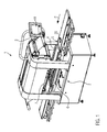
- FIG. 1 shows an example of a tray sealing machine 1 with a sealing station 2, which seals trays 20 with a cover sheet 3, and a gripper system 4, which the Shells 20 moves in a transport direction P from a feed conveyor 5 in the sealing station 2.
- the sealing station 2 has a sealing tool lower part 6 and a sealing tool upper part 7 arranged above it.
- a controller 18 controls and monitors all operations in the tray sealing machine 1.
- Fig. 2 shows a vertical sectional view of the sealing tool lower part 6 with a shell receptacle 8 and the sealing tool upper part 7 in the open position. Only in a central opening 9 of the shell receptacle 8, a shell 20 is shown. At the bottom of the sealing tool upper part 7, the lid film 3 is shown. The sealing tool lower part 6 is movable together with the shell receptacle 8 and the shell 20 by means of a not shown hoist in the direction of arrow up to the lid film 3 and the sealing tool upper part 7.
- the shell receptacle 8 has a shell support 12 for each shell 20, which defines a plane E.
- Fig. 3 shows a detailed section of the central region of the shell receptacle 8 with the shell 20 and a foil section 10 already separated from the cover foil 3, wherein the sealing die bottom part 6 and the sealing tool top part 7 are now in a closed position and form a gas-tight chamber 11 around the shell 20, to evacuate and / or aerate the interior of the shell 20, namely to form a modified atmosphere.
- the shell receptacle 8 has, for receiving the shell 20 or the shell edge 21, a shell support 12 which, for the purpose of sealing, comprises a silicone seal 13.
- the sealing tool lower part 6 has an inner space 30 below the shell receptacle 8 or below the shell 20.
- FIG. 3 also shows schematically a knife 26, which separates out of the lid film 3, the film section 10 before, during or after sealing and thereby immersed in the cutting groove 16 down.
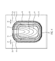
- Fig. 4 shows in an isometric view of the shell receptacle 8 with the opening 9, the shell support 12 and the cutting groove 16.
- the gas flow which can be generated via the five gassing 14 and the four evacuation openings 15, is shown.
- This U-shaped gas flow provides for modifying the atmosphere of the interior of the shell 20 to minimize, for example, the level of oxygen to preserve a foodstuff to be packaged for extended periods of time.
- a generated via the inlet opening 17 and the outlet opening 19 in the cutting groove 16, also U-shaped gas flow, in the Fig. 4 is shown as a dash-dot line, ensures removal of particles or small product residues that have settled on the shell edge 21 or in the cutting groove 16, especially the sealing surface before sealing the film portion 10 of foreign bodies such as particles or small Clean product residues.
- the inlet opening 17 has a cross-sectional area 22 which corresponds to the cross section in a feed line 24.
- the outlet opening 19 has a cross-sectional area 23 which corresponds to the cross-section in a conduit 25.
- the line 25 may extend in such a way that the escaping gas and the particles can reach down into the inner space 30 of the sealing tool lower part 6 and be collected there.
- inlet opening 17 or outlet opening 19 a plurality of bores or openings having a common cross-sectional area corresponding to the above-mentioned inlet opening 17 or outlet opening 19 are also included under the definition of inlet opening 17 or outlet opening 19.
Landscapes
- Engineering & Computer Science (AREA)
- Mechanical Engineering (AREA)
- Chemical & Material Sciences (AREA)
- Dispersion Chemistry (AREA)
- Vacuum Packaging (AREA)
- Closing Of Containers (AREA)
- Container, Conveyance, Adherence, Positioning, Of Wafer (AREA)
Abstract
Description
- Die Erfindung bezieht sich auf eine Schalenverschließmaschine gemäß dem Oberbegriff des Anspruchs 1 sowie auf ein Verfahren gemäß dem Oberbegriff des Anspruchs 9.
- Aus der
EP 1 842 776 A2 ist eine Schalenverschließmaschine mit einer Schalenaufnahme bekannt, wobei über Öffnungen in der Schalenaufnahme ein Gas zugeführt und abgeführt werden kann, um die Atmosphäre in einer mit Produkt gefüllten Schale zu modifizieren. - Die
EP 2 641 835 A1 offenbart eine Schalenverschließmaschine mit einem optimierten Siegelwerkzeug mit einer Begasungs- und einer Evakuierungsöffnung, wobei beide Öffnungen an einer gemeinsamen Seite des Siegelwerkzeugs angeordnet sind, um einen U-förmigen Strömungsverlauf ohne Turbulenzen zu erreichen. Bei Produkten, die an ihrer Oberfläche kleine Partikel wie Panadebrösel, Kräuter oder Gewürze aufweisen, können diese Partikel von der Gasströmung aufgenommen und mitgenommen werden. Im Bereich der gegenüber den Öffnungen liegenden Seite kann die Stärke der Strömung derart abfallen, dass es zum teilweisen Ablagern der Partikel auf dem Schalenrand und einer Schneidnut einer Schalenaufnahme kommt. Die Ablagerungen der Partikel auf dem Schalenrand, der zum Teil als Siegelfläche dient, können zu Mängeln der Siegelung und in Folge zu Ausschuss von nicht verwertbaren Verpackungen führen. Ablagerungen in der Schneidnut können sich im laufenden Betrieb aufhäufen und zu Problemen bzw. höheren Belastungen beim Schneidprozess führen. - Aufgabe der vorliegenden Erfindung ist es, eine verbesserte Schalenverschließmaschine zur Verfügung zu stellen, die die zuvor genannten Probleme beseitigt.
- Diese Aufgabe wird gelöst durch eine Schalenverschließmaschine mit den Merkmalen des Anspruchs 1 bzw. durch ein Verfahren zum Betrieb einer solchen Schalenverschließmaschine mit den Merkmalen des Anspruchs 9 Vorteilhafte Weiterbildungen der Erfindung sind in den Unteransprüchen angegeben.
- Die erfindungsgemäße Schalenverschließmaschine umfasst ein Siegelwerkzeugunterteil mit einer Schalenaufnahme und ein Siegelwerkzeugoberteil, wobei die Schalenaufnahme eine Schneidnut, die jeweils umlaufend um jede Öffnung für eine Schale in der Schalenaufnahme vorgesehen ist, aufweist. Die erfindungsgemäße Schalenverschließmaschine zeichnet sich dadurch aus, dass die Schalenaufnahme wenigstens eine jeweils in die Schneidnut weisende Eingangsöffnung und Ausgangsöffnung zum Gasspülen der Schneidnut aufweist. Dies führt zu einer Gasströmung innerhalb der Schneidnut, die Fremdpartikel wie Kräuter oder kleine Produktreste, die sich in der Schneidnut abgesetzt haben, in Richtung der Ausgangsöffnung und weiter durch diese Öffnung in das Innere des Siegelwerkzeugunterteils unterhalb der Schalenaufnahme oder direkt nach außen aus dem Werkzeugunterteil hinaus beispielsweise in einen Sammelbehälter befördert. So wird die Verschmutzung der Schalenaufnahme und auch der Siegelfläche am Schalenrand vermieden oder wenigstens stark verringert.
- Vorzugsweise sind die Eingangsöffnung und die Ausgangsöffnung unterhalb einer Schalenauflage der Schalenaufnahme angeordnet, um die Gasströmung in der Schneidnut zu optimieren, so dass die Schneidnut als Kanal für die Strömung von der Eingangsöffnung bis hin zur Ausgangsöffnung fungieren kann.
- Die Eingangsöffnung und die Ausgangsöffnung weisen bevorzugt eine zueinander parallele Ausrichtung auf, da bei rechteckigen Schalen mittels einer U-förmigen Strömung wenigstens drei Seiten der Schneidnut reinigbar sind.
- In einer besonders vorteilhaften Ausführung weist die Eingangsöffnung eine Querschnittsfläche von 20 bis 50 mm2 und/oder die Ausgangsöffnung eine Querschnittsfläche von 30 bis 80 mm2 auf, wobei die Eingangsöffnung auch mehrere Bohrungen mit der angegebenen Querschnittsfläche umfassen kann. Diese Ausführung sorgt einerseits für eine wirksame Gasströmung und andererseits für ein optimiertes Herausfördern der Partikel aus der Schneidnut durch die Ausgangsöffnung.
- Vorzugsweise ist eine Leitung innerhalb der Schalenaufnahme von der Ausgangsöffnung nach unten in ein Inneres des Siegelwerkzeugunterteils vorgesehen. Durch die Leitung können von der Gasströmung mitgenommene Partikel oder Verunreinigungen abgeführt werden.
- Die Schalenaufnahme weist bevorzugt jeweils mehrere Begasungsöffnungen und Evakuierungsöffnungen zum Begasen oder Gasspülen jeweils einer Schale bzw. des Raums innerhalb der Schale auf. Dabei sind die Begasungsöffnungen vorzugsweise oberhalb einer Ebene, die durch die Schalenauflage definiert ist, vorgesehen, um effizient eine modifizierte Atmosphäre im Inneren der Schale bzw der Verpackung zu erzeugen. Bevorzugt sind dabei die Eingangsöffnung und die Ausgangsöffnung jeweils auf einer gemeinsamen Seite mit den Begasungs- und Evakuierungsöffnungen angeordnet, da es an dieser gemeinsamen Seite zu keinen oder nur sehr geringen unerwünschten Ablagerungen von Partikeln in der Schneidnut und auf dem Schalenrand kommt. Alle Öffnungen weisen zweckmäßigerweise eine gemeinsame zueinander parallele Ausrichtung auf.
- Ein erfindungsgemäßes Verfahren zum Reinigen einer Schneidnut einer zuvor beschriebenen Schalenverschließmaschine zeichnet sich dadurch aus, dass vor dem Siegeln und/oder während des Siegelns ein Gas durch die Eingangsöffnung in die Schneidnut eingebracht wird und dieses Gas durch die Ausgangsöffnung wenigstens teilweise aus der Schneidnut ausgeleitet wird, um Partikel oder Fremdkörper, die sich in der Schneidnut befinden, aus dieser ganz oder teilweise zu entfernen. Als Gas ist nicht nur Sauerstoff, Stickstoff oder ein Gemisch von beiden, sondern auch Luft bzw. andere Gase und Gasgemische denkbar.
- Der Strömungsverlauf des Gases innerhalb der Schneidnut ist vorzugsweise weitestgehend kongruent zum Strömungsverlauf des Gases zum Gasspülen der Schale, um Turbulenzen zu verhindern und eine effektive Reinigung der Siegelfläche auf dem Schalenrand zu bewirken.
- Im Folgenden wird ein vorteilhaftes Ausführungsbeispiel der Erfindung anhand einer Zeichnung näher erläutert. Im Einzelnen zeigen:
- Fig. 1
- ein Beispiel einer erfindungsgemäßen Schalenverschließmaschine,
- Fig. 2
- eine schematische Schnittansicht von Siegelwerkzeugunterteil und Siegelwerkzeugoberteil,
- Fig. 3
- eine Detailansicht der Schalenaufnahme und
- Fig. 4
- eine schematische Ansicht der Schalenaufnahme.
- Gleiche Komponenten sind in den Figuren durchgängig mit gleichen Bezugszeichen versehen.
-
Figur 1 zeigt ein Beispiel einer Schalenversiegelungsmaschine 1 mit einer Siegelstation 2, die Schalen 20 mit einer Deckelfolie 3 versiegelt, und einem Greifersystem 4, das die Schalen 20 in einer Transportrichtung P von einem Zuführförderer 5 in die Siegelstation 2 bewegt. Die Siegelstation 2 weist ein Siegelwerkzeugunterteil 6 und ein darüber angeordnetes Siegelwerkzeugoberteil 7 auf. Eine Steuerung 18 steuert und überwacht alle Vorgänge in der Schalenversiegelungsmaschine 1. -
Fig. 2 zeigt eine vertikale Schnittansicht des Siegelwerkzeugunterteils 6 mit einer Schalenaufnahme 8 und des Siegelwerkzeugoberteils 7 in offener Stellung. Lediglich in einer mittleren Öffnung 9 der Schalenaufnahme 8 ist eine Schale 20 dargestellt. An der Unterseite des Siegelwerkzeugoberteils 7 ist die Deckelfolie 3 dargestellt. Das Siegelwerkzeugunterteil 6 ist zusammen mit der Schalenaufnahme 8 und der Schale 20 mittels eines nicht näher dargestellten Hubwerks in Pfeilrichtung nach oben an die Deckelfolie 3 und das Siegelwerkzeugoberteil 7 bewegbar. Die Schalenaufnahme 8 weist für jede Schale 20 eine Schalenauflage 12 auf, die eine Ebene E definiert. -
Fig. 3 zeigt einen Detailausschnitt des mittleren Bereichs der Schalenaufnahme 8 mit der Schale 20 und einem bereits aus der Deckelfolie 3 ausgetrennten Folienabschnitt 10, wobei sich das Siegelwerkzeugunterteil 6 und das Siegelwerkzeugoberteil 7 nun in einer geschlossenen Stellung befinden und eine gasdichte Kammer 11 um die Schale 20 bilden, um das Innere der Schale 20 zu evakuieren und/oder zu begasen, nämlich eine modifizierte Atmosphäre zu bilden. Die Schalenaufnahme 8 weist zur Aufnahme der Schale 20 bzw. des Schalenrands 21 eine Schalenauflage 12, die zum Zweck des Abdichtens eine Silikondichtung 13 umfasst, auf. Das Siegelwerkzeugunterteil 6 weist unterhalb der Schalenaufnahme 8 bzw. unterhalb der Schale 20 einen Innenraum 30 auf. - In dieser Schnittansicht sind rechts hinter der Schale 20 fünf Begasungsöffnungen 14 und links vier Evakuierungs- bzw. Ausgangsöffnungen 15 dargestellt, die wenigstens teilweise oberhalb der Schalenauflage 12 angeordnet sind, um eine Strömung über dem Schalenrand 21 und der Schale 20 zu erzeugen. Die Schalenaufnahme 8 weist jeweils eine um die Öffnung 9 der Schalenaufnahme 8 und um die Schalenauflage 12 ringsum laufende Schneidnut 16 auf. Im hinteren rechten Bereich von der Zeichenebene bzw. der Schneidnut 16 sind eine Eingangsöffnung 17 zum Zuführen eines Gases in die Schneidnut 16 und im hinteren linken Bereich eine Ausgangsöffnung 19 zum Austreten des Gases vorgesehen, wobei die Eingangsöffnung 17 und Ausgangsöffnung 19 vollständig unterhalb der Ebene E der Schalenauflage 12 angeordnet sind.
Fig. 3 zeigt auch schematisch ein Messer 26, das aus der Deckelfolie 3 den Folienabschnitt 10 vor, während oder nach dem Siegeln heraustrennt und dabei in die Schneidnut 16 nach unten eintaucht. -
Fig. 4 zeigt in einer isometrischen Ansicht die Schalenaufnahme 8 mit der Öffnung 9, der Schalenauflage 12 und der Schneidnut 16. Anhand gestrichelter Linien ist die Gasströmung, die über die fünf Begasungsöffnungen 14 und die vier Evakuierungsöffnungen 15 erzeugt werden kann, dargestellt. Diese U-förmige Gasströmung sorgt für ein Modifizieren der Atmosphäre des Inneren der Schale 20, um beispielsweise den Sauerstoffanteil zu minimieren, um ein zu verpackendes Lebensmittel über längere Zeit haltbar zu machen. - Eine über die Eingangsöffnung 17 und die Ausgangsöffnung 19 in der Schneidnut 16 erzeugte, ebenfalls U-förmige Gasströmung, die in der
Fig. 4 als Strich-Punkt-Linie dargestellt ist, sorgt für einen Abtransport von Partikeln oder kleinen Produktresten, die sich auf dem Schalenrand 21 oder in der Schneidnut 16 abgesetzt haben, um vor allem die Siegelfläche vor dem Aufsiegeln des Folienabschnitts 10 von Fremdkörpern wie Partikeln oder kleinen Produktresten zu reinigen. - Die Eingangsöffnung 17 weist eine Querschnittsfläche 22 auf, die dem Querschnitt in einer Zuleitung 24 entspricht auf. Analog weist die Ausgangsöffnung 19 eine Querschnittsfläche 23 auf, die dem Querschnitt in einer Leitung 25 entspricht. Die Leitung 25 kann derart verlaufen, dass das austretende Gas und die Partikel nach unten in den Innenraum 30 des Siegelwerkzeugunterteils 6 gelangen und dort gesammelt werden können.
- Unter der Definition Eingangsöffnung 17 bzw. Ausgangsöffnung 19 sind alternativ auch eine Mehrzahl von Bohrungen bzw. Öffnungen mit einer gemeinsamen Querschnittsfläche, die der oben erwähnten Eingangsöffnung 17 bzw. Ausgangsöffnung 19 entspricht, mit erfasst.
Claims (10)
- Schalenverschließmaschine (1), umfassend ein Siegelwerkzeugunterteil (6) mit einer mindestens eine Öffnung (9) für je eine Schale (20) umfassende Schalenaufnahme (8) und ein Siegelwerkzeugoberteil (7), wobei die Schalenaufnahme (8) pro Öffnung (9) je eine Schneidnut (16), die jeweils umlaufend um die Öffnung (9) in der Schalenaufnahme (8) vorgesehen ist, aufweist, dadurch gekennzeichnet, dass die Schalenaufnahme (8) wenigstens eine jeweils in die Schneidnut (16) weisende Eingangsöffnung (17) und jeweils mindestens eine in die Schneidnut (16) weisende Ausgangsöffnung (19) zum Gasspülen der Schneidnut (16) aufweist.
- Schalenverschließmaschine nach Anspruch 1, dadurch gekennzeichnet, dass die Eingangsöffnung (17) und die Ausgangsöffnung (19) unterhalb einer Ebene (E) einer Schalenauflage (12) der Schalenaufnahme (8) angeordnet sind.
- Schalenverschließmaschine nach einem der vorangehenden Ansprüche, dadurch gekennzeichnet, dass die Eingangsöffnung (17) und die Ausgangsöffnung (19) eine zueinander parallele Ausrichtung aufweisen.
- Schalenverschließmaschine nach einem der vorangehenden Ansprüche, dadurch gekennzeichnet, dass die Eingangsöffnung (17) eine Querschnittsfläche (22) von 20 bis 50 mm2 und/oder die Ausgangsöffnung (19) eine Querschnittsfläche (23) von 30 bis 80 mm2 aufweist.
- Schalenverschließmaschine nach einem der vorangehenden Ansprüche, dadurch gekennzeichnet, dass eine Leitung (25) innerhalb der Schalenaufnahme (8) von der Ausgangsöffnung (19) nach unten in einen Innenraum (30) des Siegelwerkzeugunterteils (6) vorgesehen ist.
- Schalenverschließmaschine nach einem der vorangehenden Ansprüche, dadurch gekennzeichnet, dass die Schalenaufnahme (8) jeweils mehrere Begasungsöffnungen (14) und Evakuierungsöffnungen (15) zum Begasen oder Gasspülen jeweils einer Schale (20) aufweist.
- Schalenverschließmaschine nach Anspruch 6, dadurch gekennzeichnet, dass jede der Begasungsöffnungen (14) und der Evakuierungsöffnungen (15) wenigstens teilweise oberhalb einer Ebene (E), die durch die Schalenauflage (12) definiert ist, vorgesehen sind.
- Schalenverschließmaschine nach einem der vorangehenden Ansprüche 6 oder 7, dadurch gekennzeichnet, dass die Eingangsöffnung (17) und die Ausgangsöffnung (19) jeweils auf einer gemeinsamen Seite der Schalenaufnahme (8) mit den Begasungsöffnungen (14) und Evakuierungsöffnungen (15) angeordnet sind.
- Verfahren zum Reinigen einer Schneidnut (16) einer Schalenverschließmaschine (1) gemäß einem der vorangehenden Ansprüche, dadurch gekennzeichnet, dass vor dem Siegeln und/oder während des Siegelvorgangs ein Gas durch die Eingangsöffnung (17) in die Schneidnut (16) eingebracht wird und dieses Gas durch die Ausgangsöffnung (19) wenigstens teilweise aus der Schneidnut (16) ausgeleitet wird.
- Verfahren nach Anspruch 9, dadurch gekennzeichnet, dass ein Strömungsverlauf des Gases innerhalb der Schneidnut (16) weitestgehend kongruent zu einem Strömungsverlauf des Gases zum Gasspülen der Schale (20) ist.
Priority Applications (3)
| Application Number | Priority Date | Filing Date | Title |
|---|---|---|---|
| EP15168593.0A EP3095717B1 (de) | 2015-05-21 | 2015-05-21 | Schalenverschliessmaschine |
| ES15168593.0T ES2669597T3 (es) | 2015-05-21 | 2015-05-21 | Máquina cerradora de barquetas |
| US15/159,190 US20160339484A1 (en) | 2015-05-21 | 2016-05-19 | Tray sealer |
Applications Claiming Priority (1)
| Application Number | Priority Date | Filing Date | Title |
|---|---|---|---|
| EP15168593.0A EP3095717B1 (de) | 2015-05-21 | 2015-05-21 | Schalenverschliessmaschine |
Publications (2)
| Publication Number | Publication Date |
|---|---|
| EP3095717A1 true EP3095717A1 (de) | 2016-11-23 |
| EP3095717B1 EP3095717B1 (de) | 2018-04-25 |
Family
ID=53188958
Family Applications (1)
| Application Number | Title | Priority Date | Filing Date |
|---|---|---|---|
| EP15168593.0A Not-in-force EP3095717B1 (de) | 2015-05-21 | 2015-05-21 | Schalenverschliessmaschine |
Country Status (3)
| Country | Link |
|---|---|
| US (1) | US20160339484A1 (de) |
| EP (1) | EP3095717B1 (de) |
| ES (1) | ES2669597T3 (de) |
Cited By (1)
| Publication number | Priority date | Publication date | Assignee | Title |
|---|---|---|---|---|
| CN114101207A (zh) * | 2021-11-24 | 2022-03-01 | 国网北京市电力公司 | 一种导线压接管超声波清洗装置及方法 |
Families Citing this family (4)
| Publication number | Priority date | Publication date | Assignee | Title |
|---|---|---|---|---|
| GB2576735A (en) | 2018-08-29 | 2020-03-04 | Proseal Uk Ltd | Packaging apparatus |
| IT201900010938A1 (it) * | 2019-07-04 | 2021-01-04 | Amc S R L | Macchina termosaldatrice o termoformatrice con sistema map ad alte performance, ottimizzato e autopulente |
| DE102019215451A1 (de) * | 2019-10-09 | 2021-04-15 | Multivac Sepp Haggenmüller Se & Co. Kg | Schalenverschließmaschine mit zweispuriger Förderanordnung und Förderverfahren |
| ES1266381Y (es) * | 2021-01-20 | 2021-08-03 | Luis Calvo Sanz S A | Utensilio para la limpieza del borde de sellado de latas de conservas |
Citations (4)
| Publication number | Priority date | Publication date | Assignee | Title |
|---|---|---|---|---|
| EP1842776A2 (de) | 2006-04-05 | 2007-10-10 | A.W.A.X. PROGETTAZIONE E RICERCA S.r.l. | Vorrichtung zur Verpackung von Ablagen mit Produkten in einer modifizierten Atmosphäre |
| US20110072764A1 (en) * | 2009-09-30 | 2011-03-31 | Ross Industries, Inc. | Method and apparatus for sealing containers |
| WO2011124548A1 (en) * | 2010-04-08 | 2011-10-13 | Gruppo Fabbri Vignola S.P.A. | Apparatus with opposing housings for modified atmosphere packaging of products placed in trays |
| EP2641835A1 (de) | 2012-03-23 | 2013-09-25 | Multivac Sepp Haggenmüller GmbH & Co. KG | Verpackungsmaschine mit Siegelstation zum Begasen einer Verpackung |
-
2015
- 2015-05-21 ES ES15168593.0T patent/ES2669597T3/es active Active
- 2015-05-21 EP EP15168593.0A patent/EP3095717B1/de not_active Not-in-force
-
2016
- 2016-05-19 US US15/159,190 patent/US20160339484A1/en not_active Abandoned
Patent Citations (4)
| Publication number | Priority date | Publication date | Assignee | Title |
|---|---|---|---|---|
| EP1842776A2 (de) | 2006-04-05 | 2007-10-10 | A.W.A.X. PROGETTAZIONE E RICERCA S.r.l. | Vorrichtung zur Verpackung von Ablagen mit Produkten in einer modifizierten Atmosphäre |
| US20110072764A1 (en) * | 2009-09-30 | 2011-03-31 | Ross Industries, Inc. | Method and apparatus for sealing containers |
| WO2011124548A1 (en) * | 2010-04-08 | 2011-10-13 | Gruppo Fabbri Vignola S.P.A. | Apparatus with opposing housings for modified atmosphere packaging of products placed in trays |
| EP2641835A1 (de) | 2012-03-23 | 2013-09-25 | Multivac Sepp Haggenmüller GmbH & Co. KG | Verpackungsmaschine mit Siegelstation zum Begasen einer Verpackung |
Cited By (1)
| Publication number | Priority date | Publication date | Assignee | Title |
|---|---|---|---|---|
| CN114101207A (zh) * | 2021-11-24 | 2022-03-01 | 国网北京市电力公司 | 一种导线压接管超声波清洗装置及方法 |
Also Published As
| Publication number | Publication date |
|---|---|
| ES2669597T3 (es) | 2018-05-28 |
| EP3095717B1 (de) | 2018-04-25 |
| US20160339484A1 (en) | 2016-11-24 |
Similar Documents
| Publication | Publication Date | Title |
|---|---|---|
| EP3095717B1 (de) | Schalenverschliessmaschine | |
| EP2415696B1 (de) | Sauggreifer für Lebensmittel | |
| EP3539739B1 (de) | Maschine zum slicen in die packung | |
| EP3675696B1 (de) | Frittiereinheit | |
| EP2641835B1 (de) | Verpackungsmaschine mit Siegelstation zum Begasen einer Verpackung | |
| EP3846638B1 (de) | Verfahren zum haltbarmachen von lebensmitteln in einer transport- und verkaufsverpackung | |
| DE19945500A1 (de) | Verfahren und Vorrichtung zum Entkeimen von Behältern in einer Füllmaschine | |
| DE2156889A1 (de) | Vorrichtung zum raeuchern von lebensmitteln | |
| EP1803664B1 (de) | Vorrichtung zur Unterbrechung eines kontinuierlichen Produktstroms einer Rundläuferpresse | |
| DE202007004586U1 (de) | Nuss- und Kernobstdose | |
| WO2020192959A2 (de) | Verfahren und vorrichtung zur steuerung der herstellung eines extraktes durch fest-flüssig-extraktion | |
| DE29806607U1 (de) | Fritieranlage | |
| DE102020006482B4 (de) | Vorrichtung zum Schneiden von landwirtschaftlichen Produkten und Zentralrecheneinheit mit zumindest einem Datenspeicher zur Steuerung der Vorrichtung | |
| WO2003091106A1 (de) | Verfahren und vorrichtung zur schutzgas-spülung von behältern | |
| DE3127481C2 (de) | Vorrichtung zum Entleeren von Dragierkesseln und zum Nachtrocknen und Zwischenlagern von Dragees | |
| EP3318518B1 (de) | Aufgabevorrichtung für behälterverschlüsse | |
| EP4019416B1 (de) | Siegelstation mit fliehkraftabscheider | |
| DE102014112840B4 (de) | Einlegemaschine und Einlegeverfahren | |
| EP0581123B1 (de) | Verfahren zum sauerstoffreien Verpacken von Ware | |
| EP4101312B1 (de) | Verfahren und vorrichtung zur evakuierung und rückbegasung von unverpackten produkten in nur einer vakuumkammer zur steigerung der produktionsleistung bei gleichzeitiger erhöhung der nachhaltigkeit | |
| EP0581122B1 (de) | Verfahren und Vorrichtung zum sauerstofffreien Verpacken von Ware | |
| DE29602529U1 (de) | Fritiervorrichtung | |
| EP0487115A1 (de) | Schälanlage zum mechanischen Schälen von Erd- oder Baumfrüchten | |
| EP3366141A1 (de) | Verfahren zur behandlung von lebensmitteln wie gemüse und pilzen | |
| DE132573C (de) |
Legal Events
| Date | Code | Title | Description |
|---|---|---|---|
| PUAI | Public reference made under article 153(3) epc to a published international application that has entered the european phase |
Free format text: ORIGINAL CODE: 0009012 |
|
| AK | Designated contracting states |
Kind code of ref document: A1 Designated state(s): AL AT BE BG CH CY CZ DE DK EE ES FI FR GB GR HR HU IE IS IT LI LT LU LV MC MK MT NL NO PL PT RO RS SE SI SK SM TR |
|
| AX | Request for extension of the european patent |
Extension state: BA ME |
|
| 17P | Request for examination filed |
Effective date: 20170509 |
|
| RBV | Designated contracting states (corrected) |
Designated state(s): AL AT BE BG CH CY CZ DE DK EE ES FI FR GB GR HR HU IE IS IT LI LT LU LV MC MK MT NL NO PL PT RO RS SE SI SK SM TR |
|
| GRAP | Despatch of communication of intention to grant a patent |
Free format text: ORIGINAL CODE: EPIDOSNIGR1 |
|
| RIC1 | Information provided on ipc code assigned before grant |
Ipc: B65B 61/06 20060101ALI20170922BHEP Ipc: B65B 51/00 20060101ALI20170922BHEP Ipc: B29C 65/00 20060101ALI20170922BHEP Ipc: B08B 9/032 20060101ALI20170922BHEP Ipc: B65B 31/00 20060101ALI20170922BHEP Ipc: B08B 3/02 20060101ALI20170922BHEP Ipc: B29C 65/78 20060101ALI20170922BHEP Ipc: B65B 7/16 20060101ALI20170922BHEP Ipc: B65B 31/02 20060101ALI20170922BHEP Ipc: B65B 31/04 20060101AFI20170922BHEP Ipc: B29C 65/02 20060101ALI20170922BHEP Ipc: B29C 65/74 20060101ALI20170922BHEP |
|
| GRAJ | Information related to disapproval of communication of intention to grant by the applicant or resumption of examination proceedings by the epo deleted |
Free format text: ORIGINAL CODE: EPIDOSDIGR1 |
|
| INTG | Intention to grant announced |
Effective date: 20171019 |
|
| GRAP | Despatch of communication of intention to grant a patent |
Free format text: ORIGINAL CODE: EPIDOSNIGR1 |
|
| INTC | Intention to grant announced (deleted) | ||
| INTG | Intention to grant announced |
Effective date: 20171206 |
|
| GRAA | (expected) grant |
Free format text: ORIGINAL CODE: 0009210 |
|
| GRAS | Grant fee paid |
Free format text: ORIGINAL CODE: EPIDOSNIGR3 |
|
| AK | Designated contracting states |
Kind code of ref document: B1 Designated state(s): AL AT BE BG CH CY CZ DE DK EE ES FI FR GB GR HR HU IE IS IT LI LT LU LV MC MK MT NL NO PL PT RO RS SE SI SK SM TR |
|
| REG | Reference to a national code |
Ref country code: GB Ref legal event code: FG4D Free format text: NOT ENGLISH |
|
| REG | Reference to a national code |
Ref country code: CH Ref legal event code: EP |
|
| REG | Reference to a national code |
Ref country code: AT Ref legal event code: REF Ref document number: 992612 Country of ref document: AT Kind code of ref document: T Effective date: 20180515 |
|
| REG | Reference to a national code |
Ref country code: IE Ref legal event code: FG4D Free format text: LANGUAGE OF EP DOCUMENT: GERMAN |
|
| REG | Reference to a national code |
Ref country code: DE Ref legal event code: R096 Ref document number: 502015003987 Country of ref document: DE Ref country code: FR Ref legal event code: PLFP Year of fee payment: 4 |
|
| REG | Reference to a national code |
Ref country code: ES Ref legal event code: FG2A Ref document number: 2669597 Country of ref document: ES Kind code of ref document: T3 Effective date: 20180528 |
|
| REG | Reference to a national code |
Ref country code: NL Ref legal event code: FP |
|
| REG | Reference to a national code |
Ref country code: LT Ref legal event code: MG4D |
|
| PG25 | Lapsed in a contracting state [announced via postgrant information from national office to epo] |
Ref country code: NO Free format text: LAPSE BECAUSE OF FAILURE TO SUBMIT A TRANSLATION OF THE DESCRIPTION OR TO PAY THE FEE WITHIN THE PRESCRIBED TIME-LIMIT Effective date: 20180725 Ref country code: FI Free format text: LAPSE BECAUSE OF FAILURE TO SUBMIT A TRANSLATION OF THE DESCRIPTION OR TO PAY THE FEE WITHIN THE PRESCRIBED TIME-LIMIT Effective date: 20180425 Ref country code: BG Free format text: LAPSE BECAUSE OF FAILURE TO SUBMIT A TRANSLATION OF THE DESCRIPTION OR TO PAY THE FEE WITHIN THE PRESCRIBED TIME-LIMIT Effective date: 20180725 Ref country code: LT Free format text: LAPSE BECAUSE OF FAILURE TO SUBMIT A TRANSLATION OF THE DESCRIPTION OR TO PAY THE FEE WITHIN THE PRESCRIBED TIME-LIMIT Effective date: 20180425 Ref country code: PL Free format text: LAPSE BECAUSE OF FAILURE TO SUBMIT A TRANSLATION OF THE DESCRIPTION OR TO PAY THE FEE WITHIN THE PRESCRIBED TIME-LIMIT Effective date: 20180425 Ref country code: SE Free format text: LAPSE BECAUSE OF FAILURE TO SUBMIT A TRANSLATION OF THE DESCRIPTION OR TO PAY THE FEE WITHIN THE PRESCRIBED TIME-LIMIT Effective date: 20180425 |
|
| PG25 | Lapsed in a contracting state [announced via postgrant information from national office to epo] |
Ref country code: LV Free format text: LAPSE BECAUSE OF FAILURE TO SUBMIT A TRANSLATION OF THE DESCRIPTION OR TO PAY THE FEE WITHIN THE PRESCRIBED TIME-LIMIT Effective date: 20180425 Ref country code: RS Free format text: LAPSE BECAUSE OF FAILURE TO SUBMIT A TRANSLATION OF THE DESCRIPTION OR TO PAY THE FEE WITHIN THE PRESCRIBED TIME-LIMIT Effective date: 20180425 Ref country code: GR Free format text: LAPSE BECAUSE OF FAILURE TO SUBMIT A TRANSLATION OF THE DESCRIPTION OR TO PAY THE FEE WITHIN THE PRESCRIBED TIME-LIMIT Effective date: 20180726 Ref country code: HR Free format text: LAPSE BECAUSE OF FAILURE TO SUBMIT A TRANSLATION OF THE DESCRIPTION OR TO PAY THE FEE WITHIN THE PRESCRIBED TIME-LIMIT Effective date: 20180425 |
|
| REG | Reference to a national code |
Ref country code: CH Ref legal event code: PL |
|
| PG25 | Lapsed in a contracting state [announced via postgrant information from national office to epo] |
Ref country code: PT Free format text: LAPSE BECAUSE OF FAILURE TO SUBMIT A TRANSLATION OF THE DESCRIPTION OR TO PAY THE FEE WITHIN THE PRESCRIBED TIME-LIMIT Effective date: 20180827 |
|
| REG | Reference to a national code |
Ref country code: DE Ref legal event code: R097 Ref document number: 502015003987 Country of ref document: DE |
|
| REG | Reference to a national code |
Ref country code: BE Ref legal event code: MM Effective date: 20180531 |
|
| PG25 | Lapsed in a contracting state [announced via postgrant information from national office to epo] |
Ref country code: DK Free format text: LAPSE BECAUSE OF FAILURE TO SUBMIT A TRANSLATION OF THE DESCRIPTION OR TO PAY THE FEE WITHIN THE PRESCRIBED TIME-LIMIT Effective date: 20180425 Ref country code: EE Free format text: LAPSE BECAUSE OF FAILURE TO SUBMIT A TRANSLATION OF THE DESCRIPTION OR TO PAY THE FEE WITHIN THE PRESCRIBED TIME-LIMIT Effective date: 20180425 Ref country code: MC Free format text: LAPSE BECAUSE OF FAILURE TO SUBMIT A TRANSLATION OF THE DESCRIPTION OR TO PAY THE FEE WITHIN THE PRESCRIBED TIME-LIMIT Effective date: 20180425 Ref country code: SK Free format text: LAPSE BECAUSE OF FAILURE TO SUBMIT A TRANSLATION OF THE DESCRIPTION OR TO PAY THE FEE WITHIN THE PRESCRIBED TIME-LIMIT Effective date: 20180425 Ref country code: CZ Free format text: LAPSE BECAUSE OF FAILURE TO SUBMIT A TRANSLATION OF THE DESCRIPTION OR TO PAY THE FEE WITHIN THE PRESCRIBED TIME-LIMIT Effective date: 20180425 Ref country code: RO Free format text: LAPSE BECAUSE OF FAILURE TO SUBMIT A TRANSLATION OF THE DESCRIPTION OR TO PAY THE FEE WITHIN THE PRESCRIBED TIME-LIMIT Effective date: 20180425 |
|
| REG | Reference to a national code |
Ref country code: IE Ref legal event code: MM4A |
|
| PG25 | Lapsed in a contracting state [announced via postgrant information from national office to epo] |
Ref country code: LI Free format text: LAPSE BECAUSE OF NON-PAYMENT OF DUE FEES Effective date: 20180531 Ref country code: CH Free format text: LAPSE BECAUSE OF NON-PAYMENT OF DUE FEES Effective date: 20180531 Ref country code: SM Free format text: LAPSE BECAUSE OF FAILURE TO SUBMIT A TRANSLATION OF THE DESCRIPTION OR TO PAY THE FEE WITHIN THE PRESCRIBED TIME-LIMIT Effective date: 20180425 |
|
| PLBE | No opposition filed within time limit |
Free format text: ORIGINAL CODE: 0009261 |
|
| STAA | Information on the status of an ep patent application or granted ep patent |
Free format text: STATUS: NO OPPOSITION FILED WITHIN TIME LIMIT |
|
| PG25 | Lapsed in a contracting state [announced via postgrant information from national office to epo] |
Ref country code: LU Free format text: LAPSE BECAUSE OF NON-PAYMENT OF DUE FEES Effective date: 20180521 |
|
| 26N | No opposition filed |
Effective date: 20190128 |
|
| PG25 | Lapsed in a contracting state [announced via postgrant information from national office to epo] |
Ref country code: IE Free format text: LAPSE BECAUSE OF NON-PAYMENT OF DUE FEES Effective date: 20180521 |
|
| PG25 | Lapsed in a contracting state [announced via postgrant information from national office to epo] |
Ref country code: BE Free format text: LAPSE BECAUSE OF NON-PAYMENT OF DUE FEES Effective date: 20180531 Ref country code: SI Free format text: LAPSE BECAUSE OF FAILURE TO SUBMIT A TRANSLATION OF THE DESCRIPTION OR TO PAY THE FEE WITHIN THE PRESCRIBED TIME-LIMIT Effective date: 20180425 |
|
| PG25 | Lapsed in a contracting state [announced via postgrant information from national office to epo] |
Ref country code: AL Free format text: LAPSE BECAUSE OF FAILURE TO SUBMIT A TRANSLATION OF THE DESCRIPTION OR TO PAY THE FEE WITHIN THE PRESCRIBED TIME-LIMIT Effective date: 20180425 |
|
| PG25 | Lapsed in a contracting state [announced via postgrant information from national office to epo] |
Ref country code: MT Free format text: LAPSE BECAUSE OF FAILURE TO SUBMIT A TRANSLATION OF THE DESCRIPTION OR TO PAY THE FEE WITHIN THE PRESCRIBED TIME-LIMIT Effective date: 20180425 |
|
| PG25 | Lapsed in a contracting state [announced via postgrant information from national office to epo] |
Ref country code: TR Free format text: LAPSE BECAUSE OF FAILURE TO SUBMIT A TRANSLATION OF THE DESCRIPTION OR TO PAY THE FEE WITHIN THE PRESCRIBED TIME-LIMIT Effective date: 20180425 |
|
| PG25 | Lapsed in a contracting state [announced via postgrant information from national office to epo] |
Ref country code: CY Free format text: LAPSE BECAUSE OF FAILURE TO SUBMIT A TRANSLATION OF THE DESCRIPTION OR TO PAY THE FEE WITHIN THE PRESCRIBED TIME-LIMIT Effective date: 20180425 Ref country code: MK Free format text: LAPSE BECAUSE OF NON-PAYMENT OF DUE FEES Effective date: 20180425 Ref country code: HU Free format text: LAPSE BECAUSE OF FAILURE TO SUBMIT A TRANSLATION OF THE DESCRIPTION OR TO PAY THE FEE WITHIN THE PRESCRIBED TIME-LIMIT; INVALID AB INITIO Effective date: 20150521 |
|
| PG25 | Lapsed in a contracting state [announced via postgrant information from national office to epo] |
Ref country code: IS Free format text: LAPSE BECAUSE OF FAILURE TO SUBMIT A TRANSLATION OF THE DESCRIPTION OR TO PAY THE FEE WITHIN THE PRESCRIBED TIME-LIMIT Effective date: 20180825 |
|
| REG | Reference to a national code |
Ref country code: AT Ref legal event code: MM01 Ref document number: 992612 Country of ref document: AT Kind code of ref document: T Effective date: 20200521 |
|
| PG25 | Lapsed in a contracting state [announced via postgrant information from national office to epo] |
Ref country code: AT Free format text: LAPSE BECAUSE OF NON-PAYMENT OF DUE FEES Effective date: 20200521 |
|
| PGFP | Annual fee paid to national office [announced via postgrant information from national office to epo] |
Ref country code: NL Payment date: 20230519 Year of fee payment: 9 Ref country code: IT Payment date: 20230531 Year of fee payment: 9 Ref country code: FR Payment date: 20230517 Year of fee payment: 9 Ref country code: ES Payment date: 20230621 Year of fee payment: 9 Ref country code: DE Payment date: 20230519 Year of fee payment: 9 |
|
| P01 | Opt-out of the competence of the unified patent court (upc) registered |
Effective date: 20230801 |
|
| PGFP | Annual fee paid to national office [announced via postgrant information from national office to epo] |
Ref country code: GB Payment date: 20230522 Year of fee payment: 9 |
|
| REG | Reference to a national code |
Ref country code: DE Ref legal event code: R119 Ref document number: 502015003987 Country of ref document: DE |
|
| REG | Reference to a national code |
Ref country code: NL Ref legal event code: MM Effective date: 20240601 |
|
| GBPC | Gb: european patent ceased through non-payment of renewal fee |
Effective date: 20240521 |
|
| PG25 | Lapsed in a contracting state [announced via postgrant information from national office to epo] |
Ref country code: NL Free format text: LAPSE BECAUSE OF NON-PAYMENT OF DUE FEES Effective date: 20240601 |
|
| PG25 | Lapsed in a contracting state [announced via postgrant information from national office to epo] |
Ref country code: DE Free format text: LAPSE BECAUSE OF NON-PAYMENT OF DUE FEES Effective date: 20241203 |
|
| PG25 | Lapsed in a contracting state [announced via postgrant information from national office to epo] |
Ref country code: FR Free format text: LAPSE BECAUSE OF NON-PAYMENT OF DUE FEES Effective date: 20240531 |
|
| PG25 | Lapsed in a contracting state [announced via postgrant information from national office to epo] |
Ref country code: IT Free format text: LAPSE BECAUSE OF NON-PAYMENT OF DUE FEES Effective date: 20240521 Ref country code: GB Free format text: LAPSE BECAUSE OF NON-PAYMENT OF DUE FEES Effective date: 20240521 |
|
| REG | Reference to a national code |
Ref country code: ES Ref legal event code: FD2A Effective date: 20250702 |
|
| PG25 | Lapsed in a contracting state [announced via postgrant information from national office to epo] |
Ref country code: ES Free format text: LAPSE BECAUSE OF NON-PAYMENT OF DUE FEES Effective date: 20240522 |