EP3095118B1 - System und verfahren zur verbesserung der empfindlichkeit eines sipping-systems - Google Patents
System und verfahren zur verbesserung der empfindlichkeit eines sipping-systems Download PDFInfo
- Publication number
- EP3095118B1 EP3095118B1 EP15702898.6A EP15702898A EP3095118B1 EP 3095118 B1 EP3095118 B1 EP 3095118B1 EP 15702898 A EP15702898 A EP 15702898A EP 3095118 B1 EP3095118 B1 EP 3095118B1
- Authority
- EP
- European Patent Office
- Prior art keywords
- canister
- gas
- water
- sipping
- fission
- Prior art date
- Legal status (The legal status is an assumption and is not a legal conclusion. Google has not performed a legal analysis and makes no representation as to the accuracy of the status listed.)
- Active
Links
Images


Classifications
-
- G—PHYSICS
- G21—NUCLEAR PHYSICS; NUCLEAR ENGINEERING
- G21C—NUCLEAR REACTORS
- G21C17/00—Monitoring; Testing ; Maintaining
- G21C17/06—Devices or arrangements for monitoring or testing fuel or fuel elements outside the reactor core, e.g. for burn-up, for contamination
- G21C17/07—Leak testing
-
- Y—GENERAL TAGGING OF NEW TECHNOLOGICAL DEVELOPMENTS; GENERAL TAGGING OF CROSS-SECTIONAL TECHNOLOGIES SPANNING OVER SEVERAL SECTIONS OF THE IPC; TECHNICAL SUBJECTS COVERED BY FORMER USPC CROSS-REFERENCE ART COLLECTIONS [XRACs] AND DIGESTS
- Y02—TECHNOLOGIES OR APPLICATIONS FOR MITIGATION OR ADAPTATION AGAINST CLIMATE CHANGE
- Y02E—REDUCTION OF GREENHOUSE GAS [GHG] EMISSIONS, RELATED TO ENERGY GENERATION, TRANSMISSION OR DISTRIBUTION
- Y02E30/00—Energy generation of nuclear origin
- Y02E30/30—Nuclear fission reactors
Definitions
- the present invention relates generally to a vacuum canister sipping system that is designed to detect failures in nuclear fuel assemblies and a corresponding method.
- Vacuum canister sipping detects fuel failures in nuclear fuel assemblies by isolating a fuel assembly in a chamber/canister and reducing the ambient pressure in the chamber to draw out fission gas through the cladding failures in the fuel elements of the assembly.
- the gas bubbles are collected at the top of the chamber and passed through a radiation detector (e.g., scintillation detector) to detect the presence of fission gas.
- a radiation detector e.g., scintillation detector
- a limitation of existing vacuum sipping systems is that the application of vacuum during the sipping cycle causes dissolved gasses, radioactive or otherwise, in the canister water to come out of solution and contribute to the radioactivity of the gas sample being detected. It can therefore be challenging to detect faint fuel leak signatures under pool water conditions of high and/or fluctuating ambient dissolved fission gas content.
- the present invention consists in a method as defined by the subject-matter of claim 1 and in a system as defined by the subject-matter of claim 9.
- Canister sipping equipment can detect a leaking nuclear fuel assembly only when the level of activity released by the assembly is noticeably higher than the variation in background radiation.
- There are multiple sources of background noise that can degrade the minimum detection threshold of the equipment e.g. presence of dissolved fission gas in the fuel pool and sipping canister, external gamma radiation to the radiation detector, contamination of the radiation detector, etc.).
- both the fuel assembly being tested and the vacuum canister itself are disposed in a fuel pool at the nuclear plant.
- the water in the fuel pool typically contains some fission gases (e.g., from failed/leaking fuel assemblies in the pool).
- the ambient fission gas reduces the sensitivity of the system to detecting fission gas that is leaking from the tested fuel assembly, as opposed to fission gas that is present in the ambient fuel pool environment.
- the ambient fission gas in the fuel pool may therefore impair the accuracy of failure detection or the ability to detect small failures in the fuel assembly being tested.
- the fuel pool water is typically borated, while in other types of reactors (e.g., BWR reactors), the fuel pool water is not borated.
- Various embodiments of the present invention are applicable to reactors that use borated and/or unborated water in the fuel pool.
- fuel pool and its derivatives includes similar elements of a nuclear plant where equipment can be installed and that are flooded with water to enable fuel movement.
- the refueling cavity, transfer canal, cask loading pit, etc. are all considered to be a "fuel pool” as that term is used herein.
- fuel pool water includes the water disposed in any such "fuel pool.”
- the measurement noise sources may be reduced.
- dissolved fission gas is filtered out of the pool water that is used in the canister to reduce this significant source of measurement noise.
- Reduction of dissolved fission gas in the canister can be accomplished by pumping the water out of the canister so that it is replaced by water from the pool.
- This flushing reduces the amount of dissolved fission gas in the chamber back to the normal background of dissolved fission gasses in the bulk pool inventory.
- the level of dissolved fission gasses in the bulk pool can be very high (e.g. if there are many leaking assemblies during an outage), which results in elevated background levels even after flushing with water from the pool.
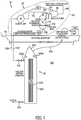
- FIG. 1 illustrates a vacuum canister sipping system 10 according to an embodiment of the present invention.
- the system 10 includes a water treatment device 20 connected to a sipping device 30.
- the water treatment device 20 includes a recirculating pump 50, one or more gas transfer membrane modules 70 (see also FIG. 2 ), a vacuum pump 80, a control system 90, an inlet water passageway 100 that leads to an inlet of the pump 50, an intermediate water passageway 110 connecting an outlet of the pump 50 to an aqueous stream inlet 70a of the module 70, a water outlet passageway 120 connecting an aqueous stream outlet 70b of the module 70 to an inlet of the sipping device 30, a strip gas inlet passage or port 70c connecting to a strip gas inlet of the module 70, an intermediate gas passageway 130 connecting a strip gas outlet 70d of the module 70 to an inlet of the vacuum pump 80, and a strip gas outlet passageway 140 connected to an outlet of the pump 80.
- the discharged air (including the fission gasses) from the vacuum pump 80 is directed either to a plant ventilation return or other location.
- the plant may wish to direct the fission-gas-laden strip gas from the passageway 140 to
- the relative positions of components of the water treatment device 20 may be switched without deviating from the scope of the present invention.
- the pump 50 may be disposed anywhere along the passageways 100, 110, 120 and/or be disposed downstream from the module 70.
- the pump 50 could alternatively be dispose downstream from the canister 500, for example downstream from the valve 520, and suction water through the system 10.
- the pump 80 could alternatively be disposed upstream from the module 70 and pump strip gas to the inlet 70c.
- many or all of the components of the water treatment device 20 may be mounted to a common frame 85 such as a skid or palette that provides for easy movement of the device 20.
- the device and frame 85 may be positioned on a floor 95 of the nuclear power plant next to the fuel pool 160 to facilitate easy connection of the passageway 100 with the fuel pool 160 and connection of the passageway 120 with the sipping device 30.
- the device 20 may alternatively be disposed on multiple frames without deviating from the scope of the present invention.
- Additional parts of the system 10 such as components of the sipping device 30 (e.g., the pump 570, detector 580, the control system 590) may also be mounted to the frame 85 to provide an easily accessible, compact system 10.
- the pump 50 moves ambient water from the fuel pool 160 sequentially through the passageway 100, the pump 50, the passageway 110, the module 70, and the passageway 120 to the sipping device 30.
- the pump 80 sucks strip gas (e.g., ambient/local air around the fuel pool or air from another source) through the inlet 70c, the module 70, the passageway 130, the pump 80, and the outlet passageway 140.
- strip gas e.g., ambient/local air around the fuel pool or air from another source
- the module 70 comprises an enclosed housing 200 through which the water flows from the aqueous inlet 70a to the aqueous outlet 70b.
- a distribution tube 210 distributes the water flow outwardly from the inlet 70a.
- the water then passes around a central baffle 220, and back to a collection tube 230 that leads to the outlet 70b.
- the strip gas flows from the strip gas inlet 70c through a plurality of hollow fiber membranes 250 and out through the outlet 70d.
- the membranes 250 allow exchange of gases between the water and strip gas, resulting in a discharge dissolved gas composition in the water that closely matches the composition of the incoming strip gas (i.e., nearly free of fission gas).
- fission gas in the incoming pool water is filtered out of the water and into the strip gas stream. Consequently, the module 70 removes fission gas from the incoming pool water from the passageway 110 and discharges clean/degassed water with less fission gas into the passageway 120. The removed fission gas combines with the strip gas in the module 70 and is expelled through the outlet 70d.
- the module 70 and membranes 250 remove fission gases, but do not remove boron from borated fuel pool water (if the fuel pool water is borated according to various embodiments). Accordingly, the clean/degassed water being used to flush the canister 500 remains borated (in embodiments in which the fuel pool water was already borated), and does not impact the boron concentration in the fuel pool. In embodiments in which the fuel pool water is borated, if fresh clean water, rather than borated pool water, were used to flush a canister 500, the water would either be borated before use, or used in an unborated state. Unborated water is preferably not used in fuel pools for certain types of reactors due to significant criticality control issues.
- the tubes 210, 230, baffle 220, and membranes 250 are part of a replaceable cartridge 270.
- the housing 200 may be opened to replace a used or fouled cartridge 270 with a fresh cartridge.
- the membranes 250 comprise hollow fiber membranes.
- the membranes 250 may take any other suitable shape (e.g., sheet membranes that separate the strip gas regions from the water regions within the module 70).
- the membranes 250 may comprise any suitable gas transfer membrane that permits transfer of fission gases therethrough without permitting water transfer.
- Liqui-Cel® Membrana Gas Transfer Modules may be used as the membranes 250. See “Membrane Contactors: An Introduction to the Technology,” Ultrapure Water® May/June 1996--UP130427. "BATMAN - Best Available Technique Minimising All Nuclides,” IVL Swedish Environmental Research Institute, April 18, 2006 , discloses other membranes that may be used as the membrane 250.
- a single module 70 is shown. However, multiple modules 70 may be used without deviating from the scope of the present invention. Multiple modules 70 may be arranged in parallel and/or series between the passageways 110, 120. Parallel modules 70 may be used to increase the flow rate of water through the water treatment device 20. Serial modules 70 may be used to increase the amount of fission gas removed from the water by the water treatment device 20.
- the module(s) 70 may be sized to collectively provide once-through processing at a liquid flow rate of approximately 25-500, 25-300, and/or 50-100 gallons/minute, which may be sufficient to turn over the full volume of the sipping canister 500 in approximately 1-2 minutes and/or less than 5, 4, 3, 2, and/or 1 minutes. An additional 1-2 minutes of flushing can be performed at the start of each cycle without a noticeable impact to the overall throughput of the sipping system 10.
- the strip gas being used in the module 70 is kept at a slight to moderate vacuum pressure.
- This vacuum causes dissolved air and other gases in the water (in addition to fission gas) to diffuse into the strip gas.
- Removal of dissolved air from the water that is used in the canister 500 during the sipping procedure improves the sensitivity of the sipping procedure to detecting small leaks in the fuel assembly 600.
- the fraction of dissolved air in the canister water less air is released from the canister water into the air bubble at the top of the canister 500 during the sipping procedure.
- the air bubble being sampled will comprise a relatively larger portion of leaked fission gas because the air bubble is not being diluted as much by air being released from the water.
- the larger concentration of any leaked fission gas in the air bubble being sampled by the detector 580 facilitates more accurate/sensitive detection of leaks.
- the control system 90 includes manual and/or automatic controls to control the pumps 50, 80, and may include additional sensors (e.g., flow/pressure sensors) that are used to determine and adjust the devices (e.g., pumps 50, 80) being controlled by the control system 90.
- additional sensors e.g., flow/pressure sensors
- the sipping device 30 includes a canister 500.
- the canister 500 has a fuel assembly opening 500a, a water inlet 500b connected to the passageway 120 by a valve 510, and a water outlet 500c connected to the fuel pool 160 via a valve 520.
- the canister 500 also includes a lid 540 that may be selectively opened and closed (e.g., manually or automatically) to uncover and cover the opening 500a.
- the device 30 also includes a passageway 560 that leads from an upper, interior end of the canister 500 to a vacuum pump 570 and detector 580 disposed outside of the pool 160.
- the pump 570 and radiation detector 580 may be mounted to the frame 85.
- the sipping device 30 works in substantially the same manner as conventional sipping devices, except that water from the water treatment device 20 is used to flush and fill the canister 500.
- a sipping device control system 590 connects to various components of the sipping device 30 such as the valves 510, 520, the pump 570, and the detector 580, to turn these components on or off at the appropriate times in the sipping cycle.
- the control system 590 may be connected to or integrally formed with the control system 90 of the water treatment device 20 to ensure that the water treatment device 20 is operated at the desired points in the sipping cycle.
- the sipping cycle proceeds through the following sequential steps:
- steps 5 and 6 may be switched in order.
- steps 3 and 4 may occur simultaneously (or an intermediate buffer tank in the passageway 120 may be used).
- Steps 7-9 may occur simultaneously.
- the degassing process performed by the water treatment device 20 and flushing the canister 500 with clean/degassed water reduces the background level of fission gases and provides a lower, more stable fission gas background level than if the flush water from the fuel pool 160 were not degassed. This results in a higher signal-to-noise ratio in the detector 580, which may result in an improved failure detection accuracy and/or the ability to detect smaller failures in the fuel assembly 600 being tested.
- the module 70 and gas transfer membranes 250 may be substituted by an alternate gas transfer component such as a spray degasser or column degasser.
- an alternate gas transfer component such as a spray degasser or column degasser.
- All or some of the components of the water treatment device 20 may be submersible in the pool 160.
- the module 70 and pump 50 may be mounted to the canister 500 and submerged in the pool 160. This may facilitate the shortening or elimination of the passageways 100, 120.
- the strip gas passageways 70c, 70d may be lengthened.
- a reservoir or buffer tank 620 may be disposed in the passageway 120 for storage of cleaned/degassed water to support a higher flushing flow rate or multi-pass treatment of pool water.
- a lower throughput water treatment device 20 may continuously fill the reservoir 620, and cleaned/degassed water in the reservoir 620 may be intermittently used to flush the canister 500 by opening the valve 510.
- the resulting flushing may be at a higher volumetric flow rate than would be possible if the flushing flow rate was limited to the flow rate possible from the pump 50 and module 70.
- the various water passageways 100, 110, 120 and gas passageways 130, 140 may comprise any type of suitable passageways (e.g., rigid or flexible hoses, pipes, etc.).
- the water treatment device 20 may be used without the sipping device 30 such that the device 20 continuously degasses the water in the pool 160 by sucking gas-laden water out of the pool through the passageway 100, degassing the water, and returning the water to the pool 160 through the open outlet end of the passageway 120.
- Such continuous degassing may improve the sensitivity of a standalone canister sipping device 30 (or other fuel assembly leak detection device (e.g., a telescope leak detection device) by lowering the ambient fission gas concentration in the pool 160 water.
- the terms "clean water,” “degassed water,” “filtered water” and the like refer to water that has been filtered to reduce the concentration of gasses (e.g., fission gases) therein. Such water is still considered clean/degassed/filtered even if it is not completely devoid of dissolved gases such as fission gases.
- the water treatment device 20 removes at least 5, 10, 20, 30, 40, 50, 60, 70, 80, 90, 95, and/or 99% of the fission gases originally present in the water such that the degassed water has at least 5, 10, 20, 30, 40, 50, 60, 70, 80, 90, 95, and/or 99% less fission gases than before the filtering/degassing.
- various techniques may be used to increase the degree of filtering/degassing (e.g., the use of larger or sequential modules 70 and/or additional degassing equipment).
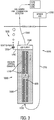
- FIG. 3 illustrates a vacuum canister sipping system 1010 according to an alternate arrangement.
- the system 1010 is substantially similar to the system 10, except that the system 1010 uses an alternative water treatment device 1020 that degasses the water already in the canister, rather than degassing water outside of the canister.
- the system 1010 includes a sipping device 1030 that is substantially similar to or identical to the above-discussed sipping device 30.
- the sipping device 1030 includes a canister 1500 and a passageway 1560 that leads from an upper, interior end of the canister 1500 to a vacuum pump 1570 and detector 1580 disposed outside of the pool.
- the sipping device 1030 also includes a control system 1590.
- the water treatment device 1020 comprises an air sparging system 1020 connected to the canister 1500.
- the air sparging system 1020 comprises a sparge air supply 1700 (e.g., a tank of compressed sparge air; a compressor configured to compress ambient air to provide pressurized sparge air, etc.).
- the sparge gas comprises air.
- the sparge gas may comprise any other type of suitable gas into which fission gasses can diffuse.
- the system 1020 includes a sparge gas supply line 1710 that extends from the sparge gas supply 1700 to a sparge gas inlet 1720 at or near the bottom of the canister 1500.
- the sparge gas inlet 1720 may lead into a gas diffuser that separates the sparge gas into small bubbles 1770.
- the system 1020 also includes a sparge gas outlet passageway 1740 connected the canister 1500 at or near the top of the canister 1500.
- the outlet passageway 1740 may open directly into the fuel pool so that fission-gas-laden sparge gas can vent into the pool or may lead to a filter/scrubber or other waste treatment device.
- a valve 1750 is connected to the outlet 1740.
- the valve 1750 may comprise a check-valve that permits sparge gas to exit the canister through the outlet 1740, while preventing liquid or gas from entering the canister 1500 via the outlet 1740 when the system 1010 applies a vacuum within the canister 1500.
- valve 1750 may comprise a valve that is controlled by the control system 1590 so that the control system 1590 closes the valve 1750 before a vacuum is applied to the canister 1500 during the sipping procedure.
- the outlet passageway 1740 comprises an instrument cluster side port in the canister1500.
- the outlet 1740 and valve 1750 are omitted altogether, and sparge gas that has bubbled through the canister 1500 and absorbed fission gasses is removed from the canister 1500 via the passageway 1560.
- sparge gas is introduced into the canister 1500 by the water treatment device 1020 after the fuel assembly 600 is loaded and the canister lid 1540 is closed. As bubbles 1770 of sparge gas rise within the sipping canister 1500, fission gasses diffuse into the bubbles 1770 and are carried to the top of the canister 1500. The sparge gas exits to the pool via the outlet 1740, and/or to the sipping system detection unit 1580 via the gas sample line 1560.
- Pressure inside the canister 1500 is preferably maintained at or near local ambient pressure within the fuel pool during the sparging process to prevent or limit the escape of fission gasses from a leaking fuel assembly 600. Venting the sparge gas out of the canister 1500 via the outlet 1740 and/or passageway 1560 may allow some or all of the sparge gas to escape and maintain the pressure inside the canister 1500 at close to ambient. Alternatively, the rates of air sparging and gas sampling may be actively controlled by the control system 1590 to maintain canister 1500 pressure at the desired conditions.
- control system 1590 is operatively connected to the water treatment device 1020 so as to control the water treatment device 1020 (e.g., by controlling the timing and rate at which sparge gas is introduced into the canister 1500 and the timing and rate at which sparge gas is allowed to exit the canister via the outlet 1740 and/or passageway 1560).
- Sparging may continue for a predetermined duration sufficient to extract the desired fraction of fission gasses from the canister water. Alternatively, sparging may continue until the radioactivity of sparge air exiting via the gas sample line 1560 reaches a desired level, as detected by the detector 1580.
- the sipping cycle continues similarly to existing sipping systems except that the background radioactivity measurements are lower than if sparging had not been performed, and leaking assemblies 600 are easier to identify.
- system 1010 operates as follows (one or more steps of which may be automated via the control system 1590):
- FIG. 4 illustrates a vacuum canister sipping system 2010 according to an alternate arrangement.
- leak detection sensitivity is improved by preventing fission gas that is present in the canister water from altering the concentration-based radioactivity of the gas bubble during the vacuum sipping procedure. This is because fission gasses that are released from the canister water into the gas bubble during the vacuum sipping procedure are released in proportion to dissolved gas (e.g., air) that is also in the canister water because the concentrations are equilibrated.
- the matching equilibrated release of such fission gasses and air reduces or eliminates the extent to which such release impacts the radioactivity detected by the detector.
- Conventional sipping procedures involve forming a clean gas bubble in the canister over the fuel assembly.
- the air bubble is formed from plant air, which is relatively reliably low in radioactivity/fission gasses.
- the air bubble is formed with this clean air at the start of the sipping procedure.
- the canister is then subjected to a vacuum pressure, which causes fission gases to leak into the canister water through any leaks in the fuel assembly. This leaked fission gas floats up and into the air bubble at the top of the canister. Samples of the air bubble are detected over time by a fission gas detector. At the start of the procedure, the air going through the detector is just clean air from the air bubble.
- the determination of a leak requires that this increase in inventory is sufficiently large as to be noticeable relative to the expected gradual increase in radioactivity caused by the ambient fission gasses already in the canister water.
- the results of the sipping procedure can be compared to the results of a control sipping procedure in which a fuel assembly is not disposed in the canister according to various arrangements.
- such use of an initial control can lead to errors based on, for example, (1) variations in fission gas concentrations in different batches of fuel pool water that are disposed in the canister during the sipping procedure, and/or (2) an artificial local increase in the fission gases in the canister water as a result of residual fission gas remaining in the canister from a prior test of a leaking fuel assembly.
- the system 2010 is configured to reduce the extent to which the concentration of fission gasses in the air bubble and gas sample loop are influenced by the action of dissolved gasses coming out of solution within the canister during the vacuum sipping procedure.
- the system 2010 includes a canister 2500 and lid 2540 that are substantially similar or identical to the canister 1500 and lid 1540 of the system 1010.
- the system 2010 incorporates a controlled carrier gas recirculation loop 2020.
- An outlet port 2550 connects at or near the top of the canister 2540 and opens into a passageway 2560.
- a carrier gas supply 2570 connects to the passageway 2560 via a valve 2580.
- the loop 2020 progresses sequentially from the passageway 2560 through a valve 2590, a pump 2600, a detector 2610 (similar or identical to the detector 580), a pump 2620, a valve 2630, and a passageway 2640, which connects to an inlet 2650 into the canister 2500 at or near the bottom of the canister 2500.
- a vent/exhaust passageway 2660 connects, by way of a valve 2670 to the loop 2020 between the detector 2610 and pump 2620.
- Pressure sensors 2690, 2700 are operatively connected to the passageways 2560, 2640, respectively.
- the carrier gas supply 2570 may comprise any suitable supply of air or other suitable gas (e.g., a compressor that compresses ambient plant air for use in the system 2010; a compressed air tank).
- suitable gas e.g., a compressor that compresses ambient plant air for use in the system 2010; a compressed air tank.
- the system 2010 includes a control system 2800 that operatively connects to the various valves 1750, 2580, 2590, 2670, 2630, sensors 2690, 2700, pumps 2600, 2620, and detector 2610 to control the operation of the system 2010.
- the control system 2800 is configured to automatically undertake some or all of the sipping procedure once the fuel assembly 600 is placed inside the canister 2500.
- the system 2010 is operated (e.g., by the control system 2800) as follows:
- the recirculation step continues until the detected radiation in the recirculating carrier gas reaches or approaches equilibrium.
- the terms "reaches” and “approaches” do not require an absolute equilibrium. Rather, they are used to identify a proximity to equilibrium. For example, as used herein, equilibrium is reached or approached when the rate of increase in detected radioactivity in the recirculating carrier gas falls below a predetermined threshold (e.g., less than a 1, 2, 3, 4, 5, 10, 15, 20, 30, and/or 40% increase in radioactivity/fission gas concentration over a predetermined time period (e.g., 1, 2, 5, 10, 20, 30, 60, 90, 120, 600, 1200 seconds)).
- a predetermined threshold e.g., less than a 1, 2, 3, 4, 5, 10, 15, 20, 30, and/or 40% increase in radioactivity/fission gas concentration over a predetermined time period (e.g., 1, 2, 5, 10, 20, 30, 60, 90, 120, 600, 1200 seconds).
- the fission gas removal features of the systems 10, 1010 and the equilibrium-based leak-detection sensitivity of the system 2010 are combined.
- such a hybrid approach can be accomplished using the system 2010.
- sparge gas is fed from the supply air 2570 through the valve 2590, pump 2600, detector 2610, pump 2620, valve 2630, passageway 2640, and inlet 2650 to introduce the sparge gas/air into the canister 2500.
- the sparge gas bubbles float up through the canister water, they absorb fission gasses from the canister water.
- the fission-gas-laden air is then vented from the system 2010 via the vent 1740 and valve 1750.
- the fission gas removal step functions in a manner similar to the fission gas removal step of the system 1010.
- a membrane filter such as the filter 70 from the system 10 may be incorporated into the system 2010 to reduce the absolute fission gas concentration in the canister 2500 water.
- the system 2010 progresses through its equilibrium and sipping steps as discussed above.
- the reduced absolute fission gas concentration in the canister water reduces the fission gas concentration in the air bubble at equilibrium, which may improve the system's leak detection sensitivity because a leak-based increase in radioactivity/fission gas concentration is larger relative to the background radioactivity/fission gas concentration in the gas bubble being sampled.
Landscapes
- Physics & Mathematics (AREA)
- Engineering & Computer Science (AREA)
- Plasma & Fusion (AREA)
- General Engineering & Computer Science (AREA)
- High Energy & Nuclear Physics (AREA)
- Monitoring And Testing Of Nuclear Reactors (AREA)
Claims (14)
- Verfahren zum Erkennen eines Fehlers in einer Kernbrennstoff-Anordnung (600) in einem Brennstofflagerbecken, wobei das Verfahren umfasst:Einbringen der Kernbrennstoff-Anordnung in einen Kanister (500) einer in dem Brennstofflagerbecken angeordneten Kanister-Vakuumsaugvorrichtung (30);Entfernen von Spaltgasen aus Brennstofflagerbeckenwasser, um entgastes Wasser zu erzeugen, wobei das Entfernen das Filtern des Brennstofflagerbeckenwassers durch eine Gastransfermembranvorrichtung (70) umfasst, die Spaltgase aus dem Brennstofflagerbeckenwasser extrahiert; undnach dem Einbringen des Kernbrennstoff-Anordnung in den Kanister, Ausführen eines Vakuumsaugvorgangs unter Verwendung der Kanister-Saugvorrichtung, um einen Fehler in der Brennstoff-Anordnung zu erkennen, indem aus der Brennstoff-Anordnung austretendes Spaltgas erkannt wird, während das entgaste Wasser in dem Kanister angeordnet ist.
- Verfahren nach Anspruch 1, ferner umfassend das Spülen des entgasten Wassers durch den Kanister nach dem Einbringen der Kernbrennstoff-Anordnung in den Kanister und vor der Ausführung, wodurch mindestens ein Teil des in dem Kanister angeordneten Brennstofflagerbeckenwassers mit dem entgasten Wasser verdrängt wird, wobei das Spülen eine Konzentration von Spaltgasen in dem in dem Kanister angeordneten Wasser reduziert.
- Verfahren nach Anspruch 2, wobei während des Spülensein Volumen des entgasten Wassers, das in den Kanister gespült wird, mindestens das Doppelte eines Volumens des Kanisters beträgt.
- Verfahren nach Anspruch 1, 2 oder 3, wobei das Entfernen das Anlegen von Vakuumdruck an ein mit der Gastransfermembranvorrichtung verwendetes Stripping-Gas umfasst, sodass die Gastransfermembranvorrichtung sowohl Spaltgas als auch gelöste Luft aus dem Brennstofflagerbeckenwasser filtert.
- Verfahren nach Anspruch 1, 2 oder 3, wobei:
wobei:
das Entfernen umfasst:Einleiten von Spülgas in den Kanister, sodass gelöste Spaltgase in dem im Kanister befindlichen Brennstofflagerbeckenwasser in das eingeleitete Spülgas diffundieren, undEntfernen mindestens eines Teils des eingeleiteten Spülgases aus dem Kanister; unddas Entfernen der Spaltgase aus dem Brennstofflagerbeckenwasser nach dem Einbringen der Kernbrennstoff-Anordnung in den Kanister und vor dem Ausführen des Vakuumsaugvorgangs erfolgt. - Verfahren nach Anspruch 5, ferner umfassend das Aufrechterhalten eines Drucks innerhalb des Kanisters bei lokalen Umgebungsdruckbedingungen im Brennstofflagerbecken während des Einleitens des Spülgases in den Kanister.
- Verfahren nach Anspruch 5, wobei ein Teil des in den Kanister eingeleiteten Spülgases aus dem Kanister aufgefangen und seine Radioaktivität gemessen wird, um einen Hintergrundwert für den Vergleich mit der während des Vakuumsaugvorgangs gemessenen Radioaktivität zu definieren.
- Verfahren nach Anspruch 5, wobei eine während des Einleitens verwendete Zufuhr von Spülgas einen geringeren Anteil an Spaltgas aufweist als ein gelöstes Gasgemisch im Brennstofflagerbeckenwasser, das vor dem Einleiten im Kanister angeordnet wird.
- Ein Kanister-Saugsystem (10), umfassend:eine Kanister-Vakuumsaugvorrichtung (30) mit einem Kanister (500), wobei die Kanister-Vakuumsaugvorrichtung dazu konfiguriert ist, einen Fehler in einer in dem Kanister angeordneten Kernbrennstoff-Anordnung (600) zu erkennen, indem Spaltgas, das während eines Vakuumsaugvorgangs der Kanister-Vakuumsaugvorrichtung aus dem Brennstoff-Anordnung austritt, erkannt wird; undeine Wasseraufbereitungsvorrichtung (20), die mit dem Kanister verbunden ist und dazu konfiguriert ist, Spaltgase aus dem Brennstofflagerbeckenwasser zu entfernen, um entgastes Wasser zu erzeugen,wobei die Wasseraufbereitungsvorrichtung dazu geeignet ist, das entgaste Wasser innerhalb des Kanisters vor dem Ausführen des Vakuumsaugverfahrens bereitzustellen,wobei die Wasseraufbereitungsvorrichtung umfasst:eine Gastransfermembranvorrichtung (70), die dazu konfiguriert ist, Spaltgase aus dem Brennstofflagerbeckenwasser zu extrahieren, das aus einem Brennstofflagerbecken extrahiert wurde, um das entgaste Wasser zu bilden, undeinen Kanister-Spülmechanismus, der dazu konfiguriert ist, das entgaste Wasser durch den Kanister zu spülen, nachdem die Kernbrennstoff-Anordnung in den Kanister eingebracht worden ist, wodurch mindestens ein Teil des im Kanister angeordneten Brennstoffbeckenwassers mit dem entgasten Wasser verdrängt wird.
- Kanister-Saugsystem nach Anspruch 9, wobei der Kanister-Spülmechanismus so konfiguriert ist, dass ein Volumen des in den Kanister gespülten entgasten Wassers mindestens das Doppelte eines Volumens des Kanisters beträgt.
- Kanister-Saugsystem nach Anspruch 9, wobei die Wasseraufbereitungsvorrichtung umfasst:eine Spaltgaszufuhr und einen Spaltgaseinlass, die mit dem Kanister verbunden sind, wobei die Wasseraufbereitungsvorrichtung dazu konfiguriert ist, Spülgas über den Einlass in den Kanister einzuleiten, sodass gelöste Spaltgase in dem in dem Kanister angeordneten Brennstofflagerbeckenwasser in das eingeleitete Spülgas diffundieren, undeinen mit dem Kanister verbundenen Spülgasauslass, wobei der Auslass so konfiguriert ist, dass das eingeleitete Spülgas den Kanister verlassen kann,wobei die Wasseraufbereitungsvorrichtung dazu konfiguriert ist, die Spaltgase aus dem Brennstofflagerbeckenwasser nach dem Einbringen der Kernbrennstoff-Anordnung in den Kanister und vor dem Ausführen des Vakuumsaugvorgangs zu entfernen.
- Kanister-Saugsystem nach Anspruch 11, wobei das System dazu konfiguriert ist, den Druck innerhalb des Kanisters auf einem lokalen Umgebungsdruck des Brennstofflagerbeckens während des Einleitens des Spülgases in den Kanister aufrechtzuhalten.
- Kanister-Saugsystem nach Anspruch 11, wobei die Kanister-Vakuumsaugvorrichtung dazu konfiguriert ist, einen Teil des in den Kanister eingeleiteten Spülgases aufzufangen und eine Radioaktivität des gesammelten Spülgases zu messen, um einen Hintergrundwert zum Vergleich mit einer während des Vakuumsaugvorgangs gemessenen Radioaktivität zu definieren.
- Kanister-Saugsystem nach Anspruch 11, wobei die Spaltgaszufuhr einen geringeren Anteil an Spaltgas aufweist als ein gelöstes Gasgemisch in dem vor dem Betrieb der Wasseraufbereitungsvorrichtung im Kanister angeordneten Brennstofflagerbeckenwasser.
Applications Claiming Priority (2)
| Application Number | Priority Date | Filing Date | Title |
|---|---|---|---|
| US201461928301P | 2014-01-16 | 2014-01-16 | |
| PCT/US2015/011752 WO2015109182A2 (en) | 2014-01-16 | 2015-01-16 | System and method for improving sensitivity of a sipping system |
Publications (2)
| Publication Number | Publication Date |
|---|---|
| EP3095118A2 EP3095118A2 (de) | 2016-11-23 |
| EP3095118B1 true EP3095118B1 (de) | 2018-10-03 |
Family
ID=52450605
Family Applications (1)
| Application Number | Title | Priority Date | Filing Date |
|---|---|---|---|
| EP15702898.6A Active EP3095118B1 (de) | 2014-01-16 | 2015-01-16 | System und verfahren zur verbesserung der empfindlichkeit eines sipping-systems |
Country Status (8)
| Country | Link |
|---|---|
| US (1) | US11170904B2 (de) |
| EP (1) | EP3095118B1 (de) |
| JP (1) | JP6693879B2 (de) |
| KR (1) | KR102309025B1 (de) |
| CN (1) | CN105981109B (de) |
| CA (1) | CA2936654C (de) |
| ES (1) | ES2691943T3 (de) |
| WO (1) | WO2015109182A2 (de) |
Families Citing this family (15)
| Publication number | Priority date | Publication date | Assignee | Title |
|---|---|---|---|---|
| FR3062946B1 (fr) * | 2017-02-15 | 2021-07-23 | Areva Np | Dispositif et procede de controle d'etancheite par ressuage d'un assemblage de combustible nucleaire |
| JP7101687B2 (ja) | 2017-04-20 | 2022-07-15 | ドミニオン エンジニアリング,インク. | 原子力プラント用モジュール式水浄化システム |
| DE102017114835B3 (de) * | 2017-07-04 | 2018-10-31 | Framatome Gmbh | Analysevorrichtung zum Nachweis von Spaltprodukten durch Messung einer Radioaktivität und Analysesystem |
| CN107564594A (zh) * | 2017-08-23 | 2018-01-09 | 福建福清核电有限公司 | 一种核电站燃料包壳破口当量的评价方法 |
| CN108182980A (zh) * | 2017-11-27 | 2018-06-19 | 中核控制系统工程有限公司 | 一种适用于燃料包壳在线啜吸检测装置的气路系统 |
| KR101948535B1 (ko) * | 2017-12-26 | 2019-03-05 | 세안기술 주식회사 | 가스순환라인에 대한 가스누출 감지, 가스누출발생구간 검출 및 우회순환라인을 자동으로 형성하는 기능을 구비한 캐니스터 건조장치 및 그 건조장치의 제어방법 |
| CN109599196B (zh) * | 2018-12-19 | 2019-08-09 | 西安交通大学 | 一种燃料元件破损后裂变气体泄漏测量实验装置及方法 |
| CN111354488B (zh) * | 2018-12-21 | 2022-08-19 | 核动力运行研究所 | 一种核燃料组件真空离线啜吸检测装置及方法 |
| CN111354485B (zh) * | 2018-12-21 | 2024-08-09 | 核动力运行研究所 | 核燃料组件离线泄漏监测啜吸室新型密封结构 |
| CN110911022A (zh) * | 2019-10-14 | 2020-03-24 | 湖南汉华京电清洁能源科技有限公司 | 定量检测燃料组件破损程度的方法 |
| CN112002449B (zh) * | 2020-07-27 | 2024-09-10 | 中核武汉核电运行技术股份有限公司 | 离线真空啜吸检测与安全控制系统及控制方法 |
| CN111799004B (zh) * | 2020-07-27 | 2024-10-18 | 中核武汉核电运行技术股份有限公司 | 真空离线啜吸系统及检测方法 |
| CN112002450B (zh) * | 2020-08-24 | 2024-10-18 | 中核武汉核电运行技术股份有限公司 | 燃料组件固定隔离装置 |
| CN119339980A (zh) * | 2023-07-19 | 2025-01-21 | 中核武汉核电运行技术股份有限公司 | 一种燃料组件真空离线啜吸模拟装置 |
| US20250266179A1 (en) * | 2024-02-15 | 2025-08-21 | Robert D. Varrin, Jr. | Method and Apparatus to Test for Defects in Irradiated Nuclear Fuel |
Family Cites Families (21)
| Publication number | Priority date | Publication date | Assignee | Title |
|---|---|---|---|---|
| JPS515486A (de) * | 1974-07-03 | 1976-01-17 | Hitachi Ltd | |
| US4034599A (en) * | 1975-06-18 | 1977-07-12 | General Electric Company | Device for locating defective fuel |
| JPS52106096A (en) * | 1976-03-03 | 1977-09-06 | Hitachi Ltd | Broken fuel detecting method |
| JPS5862596A (ja) * | 1981-10-09 | 1983-04-14 | 株式会社日立製作所 | 破損燃料検出法 |
| CN1016471B (zh) | 1985-12-20 | 1992-04-29 | 法玛通公司 | 核燃料组件中包壳缺陷检测的方法和装置 |
| JPS63266395A (ja) * | 1987-04-24 | 1988-11-02 | Mitsubishi Atom Power Ind Inc | 燃料漏洩検査装置 |
| FR2666924B1 (fr) * | 1990-09-13 | 1992-12-18 | Framatome Sa | Procede et dispositif de detection de fuite sur un element combustible d'un assemblage pour reacteur nucleaire. |
| US5546435A (en) | 1992-11-16 | 1996-08-13 | Abb Atom Ab | Fission product leak detection in a pressurized-water reactor |
| US5457720A (en) | 1994-04-15 | 1995-10-10 | General Electric Company | System for krypton-xenon concentration, separation and measurement for rapid detection of defective nuclear fuel bundles |
| JP2000002787A (ja) * | 1998-06-16 | 2000-01-07 | Toshiba Eng Co Ltd | 原子力プラントの過酸化水素濃度低減装置 |
| JP3691970B2 (ja) * | 1998-09-10 | 2005-09-07 | 株式会社東芝 | 破損燃料集合体の検出方法およびその装置 |
| JP2000162373A (ja) * | 1998-11-26 | 2000-06-16 | Hitachi Ltd | 燃料破損検査方法及び燃料破損検査装置 |
| DE19924066A1 (de) * | 1999-05-26 | 2000-04-20 | Siemens Ag | Verfahren und Vorrichtung zum Prüfen von Kernreaktor-Brennelementen |
| AU2003233490A1 (en) * | 2002-04-08 | 2003-10-27 | Dominion Engineering, Inc. | Liquid degassing system for power plant system layup |
| CN100341803C (zh) | 2003-09-29 | 2007-10-10 | 张侯国 | 小型污水循环处理装置 |
| JP2006029930A (ja) * | 2004-07-15 | 2006-02-02 | Hitachi Ltd | 核燃料の炉外シッピング装置及び炉外シッピング方法 |
| JP2005265856A (ja) * | 2005-05-12 | 2005-09-29 | Toshiba Corp | 破損燃料集合体の検出方法およびその装置 |
| JP2012052818A (ja) * | 2010-08-31 | 2012-03-15 | Mitsubishi Heavy Ind Ltd | 燃料棒の漏洩検査方法 |
| US8414685B2 (en) | 2010-09-08 | 2013-04-09 | Westinghouse Electric Company Llc | System and method for removal of dissolved gases in makeup water of a water-cooled nuclear reactor |
| CN202034074U (zh) | 2011-03-30 | 2011-11-09 | 西北核技术研究所 | 液态放射性废物处理装置 |
| CN103405945B (zh) * | 2013-07-31 | 2016-02-10 | 中科华核电技术研究院有限公司 | 脱除核电站反应堆冷却剂中溶解气体的脱气装置及其方法 |
-
2015
- 2015-01-16 CN CN201580004792.2A patent/CN105981109B/zh active Active
- 2015-01-16 KR KR1020167021817A patent/KR102309025B1/ko active Active
- 2015-01-16 JP JP2016543221A patent/JP6693879B2/ja active Active
- 2015-01-16 ES ES15702898.6T patent/ES2691943T3/es active Active
- 2015-01-16 CA CA2936654A patent/CA2936654C/en active Active
- 2015-01-16 US US15/104,971 patent/US11170904B2/en active Active
- 2015-01-16 EP EP15702898.6A patent/EP3095118B1/de active Active
- 2015-01-16 WO PCT/US2015/011752 patent/WO2015109182A2/en not_active Ceased
Non-Patent Citations (1)
| Title |
|---|
| None * |
Also Published As
| Publication number | Publication date |
|---|---|
| WO2015109182A2 (en) | 2015-07-23 |
| WO2015109182A3 (en) | 2015-10-22 |
| EP3095118A2 (de) | 2016-11-23 |
| JP2017503170A (ja) | 2017-01-26 |
| US11170904B2 (en) | 2021-11-09 |
| CA2936654A1 (en) | 2015-07-23 |
| KR20160106727A (ko) | 2016-09-12 |
| CN105981109A (zh) | 2016-09-28 |
| CN105981109B (zh) | 2018-09-14 |
| ES2691943T3 (es) | 2018-11-29 |
| KR102309025B1 (ko) | 2021-10-07 |
| JP6693879B2 (ja) | 2020-05-13 |
| US20170032854A1 (en) | 2017-02-02 |
| CA2936654C (en) | 2022-08-09 |
Similar Documents
| Publication | Publication Date | Title |
|---|---|---|
| CA2936654C (en) | System and method for improving sensitivity of a sipping system | |
| US4034599A (en) | Device for locating defective fuel | |
| US5414742A (en) | Leak-detection system and method for detecting a leaking container | |
| CA2481540C (en) | Liquid degassing system for power plant system layup | |
| US6570949B2 (en) | Method and apparatus for testing nuclear reactor fuel assemblies | |
| JP2000507697A (ja) | 漏洩検出装置および方法 | |
| US4696788A (en) | Process and device for detecting defective cladding sheaths in a nuclear fuel assembly | |
| CN85109072A (zh) | 核燃料组件中包壳缺陷检测的方法和装置 | |
| KR101519799B1 (ko) | 경수로 원자력발전소 증기발생기 세관 누설 온라인 감시를 위한 자외선-가시광선 분광광도측정장치와 이온크로마토그래피를 이용하는 붕소이온의 검출방법 및 검출시스템 | |
| CA2500737C (en) | Device and method for extracting liquid samples | |
| WO2003034442A1 (en) | Method and device for liquid coolant nuclear reactor fuel rod assembly handling and leakage monitoring | |
| WO2025174401A1 (en) | Method and apparatus to test for defects in irradiated nuclear fuel | |
| EP0684612B1 (de) | System und Verfahren zur Erkennung eines einzelnen lecken Kernbrennstabs mit hieraus auslaufenden radioaktiven Stoffen | |
| JPS6025756B2 (ja) | 破損燃料検出方法 | |
| JP2000002782A (ja) | 原子炉格納容器内雰囲気制御装置 | |
| JP2006029930A (ja) | 核燃料の炉外シッピング装置及び炉外シッピング方法 | |
| CN221006928U (zh) | 船舶压载水采集装置 | |
| KR20180047155A (ko) | 칼란드리아 내부 구조물 검사장비의 방사선 피폭 방지장치 | |
| RU2859914C1 (ru) | Способ оперативного контроля герметичности топливных сборок водо-водяного реактора при его перегрузке | |
| CN118402015A (zh) | 用于在核设施的池中升高或降低核燃料组件的装置 | |
| KR100241142B1 (ko) | 에어 이젝터를 이용한 자동 시료 채취 장치 | |
| Osborne | Device for locating defective fuel | |
| CN107004448B (zh) | 用于对燃料棒盒实施密封度检测的装置和方法 | |
| JPS60166841A (ja) | 油中ガス自動分析装置 | |
| JP2005265856A (ja) | 破損燃料集合体の検出方法およびその装置 |
Legal Events
| Date | Code | Title | Description |
|---|---|---|---|
| PUAI | Public reference made under article 153(3) epc to a published international application that has entered the european phase |
Free format text: ORIGINAL CODE: 0009012 |
|
| 17P | Request for examination filed |
Effective date: 20160720 |
|
| AK | Designated contracting states |
Kind code of ref document: A2 Designated state(s): AL AT BE BG CH CY CZ DE DK EE ES FI FR GB GR HR HU IE IS IT LI LT LU LV MC MK MT NL NO PL PT RO RS SE SI SK SM TR |
|
| AX | Request for extension of the european patent |
Extension state: BA ME |
|
| DAX | Request for extension of the european patent (deleted) | ||
| GRAP | Despatch of communication of intention to grant a patent |
Free format text: ORIGINAL CODE: EPIDOSNIGR1 |
|
| STAA | Information on the status of an ep patent application or granted ep patent |
Free format text: STATUS: GRANT OF PATENT IS INTENDED |
|
| INTG | Intention to grant announced |
Effective date: 20180508 |
|
| GRAS | Grant fee paid |
Free format text: ORIGINAL CODE: EPIDOSNIGR3 |
|
| GRAA | (expected) grant |
Free format text: ORIGINAL CODE: 0009210 |
|
| STAA | Information on the status of an ep patent application or granted ep patent |
Free format text: STATUS: THE PATENT HAS BEEN GRANTED |
|
| AK | Designated contracting states |
Kind code of ref document: B1 Designated state(s): AL AT BE BG CH CY CZ DE DK EE ES FI FR GB GR HR HU IE IS IT LI LT LU LV MC MK MT NL NO PL PT RO RS SE SI SK SM TR |
|
| REG | Reference to a national code |
Ref country code: GB Ref legal event code: FG4D |
|
| REG | Reference to a national code |
Ref country code: CH Ref legal event code: EP Ref country code: AT Ref legal event code: REF Ref document number: 1049497 Country of ref document: AT Kind code of ref document: T Effective date: 20181015 |
|
| REG | Reference to a national code |
Ref country code: IE Ref legal event code: FG4D Ref country code: DE Ref legal event code: R096 Ref document number: 602015017452 Country of ref document: DE |
|
| REG | Reference to a national code |
Ref country code: SE Ref legal event code: TRGR |
|
| REG | Reference to a national code |
Ref country code: ES Ref legal event code: FG2A Ref document number: 2691943 Country of ref document: ES Kind code of ref document: T3 Effective date: 20181129 |
|
| REG | Reference to a national code |
Ref country code: NL Ref legal event code: MP Effective date: 20181003 |
|
| REG | Reference to a national code |
Ref country code: LT Ref legal event code: MG4D |
|
| REG | Reference to a national code |
Ref country code: AT Ref legal event code: MK05 Ref document number: 1049497 Country of ref document: AT Kind code of ref document: T Effective date: 20181003 |
|
| PG25 | Lapsed in a contracting state [announced via postgrant information from national office to epo] |
Ref country code: NL Free format text: LAPSE BECAUSE OF FAILURE TO SUBMIT A TRANSLATION OF THE DESCRIPTION OR TO PAY THE FEE WITHIN THE PRESCRIBED TIME-LIMIT Effective date: 20181003 |
|
| PG25 | Lapsed in a contracting state [announced via postgrant information from national office to epo] |
Ref country code: IS Free format text: LAPSE BECAUSE OF FAILURE TO SUBMIT A TRANSLATION OF THE DESCRIPTION OR TO PAY THE FEE WITHIN THE PRESCRIBED TIME-LIMIT Effective date: 20190203 Ref country code: LT Free format text: LAPSE BECAUSE OF FAILURE TO SUBMIT A TRANSLATION OF THE DESCRIPTION OR TO PAY THE FEE WITHIN THE PRESCRIBED TIME-LIMIT Effective date: 20181003 Ref country code: CZ Free format text: LAPSE BECAUSE OF FAILURE TO SUBMIT A TRANSLATION OF THE DESCRIPTION OR TO PAY THE FEE WITHIN THE PRESCRIBED TIME-LIMIT Effective date: 20181003 Ref country code: BG Free format text: LAPSE BECAUSE OF FAILURE TO SUBMIT A TRANSLATION OF THE DESCRIPTION OR TO PAY THE FEE WITHIN THE PRESCRIBED TIME-LIMIT Effective date: 20190103 Ref country code: NO Free format text: LAPSE BECAUSE OF FAILURE TO SUBMIT A TRANSLATION OF THE DESCRIPTION OR TO PAY THE FEE WITHIN THE PRESCRIBED TIME-LIMIT Effective date: 20190103 Ref country code: HR Free format text: LAPSE BECAUSE OF FAILURE TO SUBMIT A TRANSLATION OF THE DESCRIPTION OR TO PAY THE FEE WITHIN THE PRESCRIBED TIME-LIMIT Effective date: 20181003 Ref country code: AT Free format text: LAPSE BECAUSE OF FAILURE TO SUBMIT A TRANSLATION OF THE DESCRIPTION OR TO PAY THE FEE WITHIN THE PRESCRIBED TIME-LIMIT Effective date: 20181003 Ref country code: PL Free format text: LAPSE BECAUSE OF FAILURE TO SUBMIT A TRANSLATION OF THE DESCRIPTION OR TO PAY THE FEE WITHIN THE PRESCRIBED TIME-LIMIT Effective date: 20181003 Ref country code: LV Free format text: LAPSE BECAUSE OF FAILURE TO SUBMIT A TRANSLATION OF THE DESCRIPTION OR TO PAY THE FEE WITHIN THE PRESCRIBED TIME-LIMIT Effective date: 20181003 Ref country code: FI Free format text: LAPSE BECAUSE OF FAILURE TO SUBMIT A TRANSLATION OF THE DESCRIPTION OR TO PAY THE FEE WITHIN THE PRESCRIBED TIME-LIMIT Effective date: 20181003 |
|
| PG25 | Lapsed in a contracting state [announced via postgrant information from national office to epo] |
Ref country code: RS Free format text: LAPSE BECAUSE OF FAILURE TO SUBMIT A TRANSLATION OF THE DESCRIPTION OR TO PAY THE FEE WITHIN THE PRESCRIBED TIME-LIMIT Effective date: 20181003 Ref country code: AL Free format text: LAPSE BECAUSE OF FAILURE TO SUBMIT A TRANSLATION OF THE DESCRIPTION OR TO PAY THE FEE WITHIN THE PRESCRIBED TIME-LIMIT Effective date: 20181003 Ref country code: PT Free format text: LAPSE BECAUSE OF FAILURE TO SUBMIT A TRANSLATION OF THE DESCRIPTION OR TO PAY THE FEE WITHIN THE PRESCRIBED TIME-LIMIT Effective date: 20190203 Ref country code: GR Free format text: LAPSE BECAUSE OF FAILURE TO SUBMIT A TRANSLATION OF THE DESCRIPTION OR TO PAY THE FEE WITHIN THE PRESCRIBED TIME-LIMIT Effective date: 20190104 |
|
| REG | Reference to a national code |
Ref country code: DE Ref legal event code: R097 Ref document number: 602015017452 Country of ref document: DE |
|
| PG25 | Lapsed in a contracting state [announced via postgrant information from national office to epo] |
Ref country code: DK Free format text: LAPSE BECAUSE OF FAILURE TO SUBMIT A TRANSLATION OF THE DESCRIPTION OR TO PAY THE FEE WITHIN THE PRESCRIBED TIME-LIMIT Effective date: 20181003 Ref country code: IT Free format text: LAPSE BECAUSE OF FAILURE TO SUBMIT A TRANSLATION OF THE DESCRIPTION OR TO PAY THE FEE WITHIN THE PRESCRIBED TIME-LIMIT Effective date: 20181003 |
|
| REG | Reference to a national code |
Ref country code: DE Ref legal event code: R119 Ref document number: 602015017452 Country of ref document: DE |
|
| PLBE | No opposition filed within time limit |
Free format text: ORIGINAL CODE: 0009261 |
|
| STAA | Information on the status of an ep patent application or granted ep patent |
Free format text: STATUS: NO OPPOSITION FILED WITHIN TIME LIMIT |
|
| PG25 | Lapsed in a contracting state [announced via postgrant information from national office to epo] |
Ref country code: SK Free format text: LAPSE BECAUSE OF FAILURE TO SUBMIT A TRANSLATION OF THE DESCRIPTION OR TO PAY THE FEE WITHIN THE PRESCRIBED TIME-LIMIT Effective date: 20181003 Ref country code: SM Free format text: LAPSE BECAUSE OF FAILURE TO SUBMIT A TRANSLATION OF THE DESCRIPTION OR TO PAY THE FEE WITHIN THE PRESCRIBED TIME-LIMIT Effective date: 20181003 Ref country code: EE Free format text: LAPSE BECAUSE OF FAILURE TO SUBMIT A TRANSLATION OF THE DESCRIPTION OR TO PAY THE FEE WITHIN THE PRESCRIBED TIME-LIMIT Effective date: 20181003 Ref country code: RO Free format text: LAPSE BECAUSE OF FAILURE TO SUBMIT A TRANSLATION OF THE DESCRIPTION OR TO PAY THE FEE WITHIN THE PRESCRIBED TIME-LIMIT Effective date: 20181003 Ref country code: MC Free format text: LAPSE BECAUSE OF FAILURE TO SUBMIT A TRANSLATION OF THE DESCRIPTION OR TO PAY THE FEE WITHIN THE PRESCRIBED TIME-LIMIT Effective date: 20181003 |
|
| REG | Reference to a national code |
Ref country code: CH Ref legal event code: PL |
|
| 26N | No opposition filed |
Effective date: 20190704 |
|
| PG25 | Lapsed in a contracting state [announced via postgrant information from national office to epo] |
Ref country code: LU Free format text: LAPSE BECAUSE OF NON-PAYMENT OF DUE FEES Effective date: 20190116 |
|
| REG | Reference to a national code |
Ref country code: BE Ref legal event code: MM Effective date: 20190131 |
|
| REG | Reference to a national code |
Ref country code: IE Ref legal event code: MM4A |
|
| PG25 | Lapsed in a contracting state [announced via postgrant information from national office to epo] |
Ref country code: SI Free format text: LAPSE BECAUSE OF FAILURE TO SUBMIT A TRANSLATION OF THE DESCRIPTION OR TO PAY THE FEE WITHIN THE PRESCRIBED TIME-LIMIT Effective date: 20181003 Ref country code: DE Free format text: LAPSE BECAUSE OF NON-PAYMENT OF DUE FEES Effective date: 20190801 |
|
| PG25 | Lapsed in a contracting state [announced via postgrant information from national office to epo] |
Ref country code: BE Free format text: LAPSE BECAUSE OF NON-PAYMENT OF DUE FEES Effective date: 20190131 |
|
| PG25 | Lapsed in a contracting state [announced via postgrant information from national office to epo] |
Ref country code: LI Free format text: LAPSE BECAUSE OF NON-PAYMENT OF DUE FEES Effective date: 20190131 Ref country code: CH Free format text: LAPSE BECAUSE OF NON-PAYMENT OF DUE FEES Effective date: 20190131 |
|
| PG25 | Lapsed in a contracting state [announced via postgrant information from national office to epo] |
Ref country code: IE Free format text: LAPSE BECAUSE OF NON-PAYMENT OF DUE FEES Effective date: 20190116 |
|
| PG25 | Lapsed in a contracting state [announced via postgrant information from national office to epo] |
Ref country code: TR Free format text: LAPSE BECAUSE OF FAILURE TO SUBMIT A TRANSLATION OF THE DESCRIPTION OR TO PAY THE FEE WITHIN THE PRESCRIBED TIME-LIMIT Effective date: 20181003 |
|
| PG25 | Lapsed in a contracting state [announced via postgrant information from national office to epo] |
Ref country code: MT Free format text: LAPSE BECAUSE OF NON-PAYMENT OF DUE FEES Effective date: 20190116 |
|
| PG25 | Lapsed in a contracting state [announced via postgrant information from national office to epo] |
Ref country code: CY Free format text: LAPSE BECAUSE OF FAILURE TO SUBMIT A TRANSLATION OF THE DESCRIPTION OR TO PAY THE FEE WITHIN THE PRESCRIBED TIME-LIMIT Effective date: 20181003 |
|
| PG25 | Lapsed in a contracting state [announced via postgrant information from national office to epo] |
Ref country code: HU Free format text: LAPSE BECAUSE OF FAILURE TO SUBMIT A TRANSLATION OF THE DESCRIPTION OR TO PAY THE FEE WITHIN THE PRESCRIBED TIME-LIMIT; INVALID AB INITIO Effective date: 20150116 |
|
| PG25 | Lapsed in a contracting state [announced via postgrant information from national office to epo] |
Ref country code: MK Free format text: LAPSE BECAUSE OF FAILURE TO SUBMIT A TRANSLATION OF THE DESCRIPTION OR TO PAY THE FEE WITHIN THE PRESCRIBED TIME-LIMIT Effective date: 20181003 |
|
| PGFP | Annual fee paid to national office [announced via postgrant information from national office to epo] |
Ref country code: GB Payment date: 20251204 Year of fee payment: 12 |
|
| PGFP | Annual fee paid to national office [announced via postgrant information from national office to epo] |
Ref country code: FR Payment date: 20251208 Year of fee payment: 12 |
|
| PGFP | Annual fee paid to national office [announced via postgrant information from national office to epo] |
Ref country code: SE Payment date: 20251210 Year of fee payment: 12 |
|
| PGFP | Annual fee paid to national office [announced via postgrant information from national office to epo] |
Ref country code: ES Payment date: 20260209 Year of fee payment: 12 |