EP3094444B1 - Bearbeitungsvorrichtung und -verfahren zur laserbearbeitung einer oberfläche - Google Patents
Bearbeitungsvorrichtung und -verfahren zur laserbearbeitung einer oberfläche Download PDFInfo
- Publication number
- EP3094444B1 EP3094444B1 EP15700558.8A EP15700558A EP3094444B1 EP 3094444 B1 EP3094444 B1 EP 3094444B1 EP 15700558 A EP15700558 A EP 15700558A EP 3094444 B1 EP3094444 B1 EP 3094444B1
- Authority
- EP
- European Patent Office
- Prior art keywords
- unit
- optical axis
- module
- partial beams
- laser
- Prior art date
- Legal status (The legal status is an assumption and is not a legal conclusion. Google has not performed a legal analysis and makes no representation as to the accuracy of the status listed.)
- Active
Links
Images


Classifications
-
- B—PERFORMING OPERATIONS; TRANSPORTING
- B23—MACHINE TOOLS; METAL-WORKING NOT OTHERWISE PROVIDED FOR
- B23K—SOLDERING OR UNSOLDERING; WELDING; CLADDING OR PLATING BY SOLDERING OR WELDING; CUTTING BY APPLYING HEAT LOCALLY, e.g. FLAME CUTTING; WORKING BY LASER BEAM
- B23K26/00—Working by laser beam, e.g. welding, cutting or boring
- B23K26/02—Positioning or observing the workpiece, e.g. with respect to the point of impact; Aligning, aiming or focusing the laser beam
- B23K26/06—Shaping the laser beam, e.g. by masks or multi-focusing
- B23K26/067—Dividing the beam into multiple beams, e.g. multifocusing
- B23K26/0676—Dividing the beam into multiple beams, e.g. multifocusing into dependently operating sub-beams, e.g. an array of spots with fixed spatial relationship or for performing simultaneously identical operations
-
- B—PERFORMING OPERATIONS; TRANSPORTING
- B23—MACHINE TOOLS; METAL-WORKING NOT OTHERWISE PROVIDED FOR
- B23K—SOLDERING OR UNSOLDERING; WELDING; CLADDING OR PLATING BY SOLDERING OR WELDING; CUTTING BY APPLYING HEAT LOCALLY, e.g. FLAME CUTTING; WORKING BY LASER BEAM
- B23K26/00—Working by laser beam, e.g. welding, cutting or boring
- B23K26/02—Positioning or observing the workpiece, e.g. with respect to the point of impact; Aligning, aiming or focusing the laser beam
- B23K26/06—Shaping the laser beam, e.g. by masks or multi-focusing
- B23K26/064—Shaping the laser beam, e.g. by masks or multi-focusing by means of optical elements, e.g. lenses, mirrors or prisms
-
- B—PERFORMING OPERATIONS; TRANSPORTING
- B23—MACHINE TOOLS; METAL-WORKING NOT OTHERWISE PROVIDED FOR
- B23K—SOLDERING OR UNSOLDERING; WELDING; CLADDING OR PLATING BY SOLDERING OR WELDING; CUTTING BY APPLYING HEAT LOCALLY, e.g. FLAME CUTTING; WORKING BY LASER BEAM
- B23K26/00—Working by laser beam, e.g. welding, cutting or boring
- B23K26/352—Working by laser beam, e.g. welding, cutting or boring for surface treatment
-
- G—PHYSICS
- G02—OPTICS
- G02B—OPTICAL ELEMENTS, SYSTEMS OR APPARATUS
- G02B27/00—Optical systems or apparatus not provided for by any of the groups G02B1/00 - G02B26/00, G02B30/00
- G02B27/10—Beam splitting or combining systems
- G02B27/1086—Beam splitting or combining systems operating by diffraction only
- G02B27/1093—Beam splitting or combining systems operating by diffraction only for use with monochromatic radiation only, e.g. devices for splitting a single laser source
-
- G—PHYSICS
- G02—OPTICS
- G02B—OPTICAL ELEMENTS, SYSTEMS OR APPARATUS
- G02B26/00—Optical devices or arrangements for the control of light using movable or deformable optical elements
- G02B26/08—Optical devices or arrangements for the control of light using movable or deformable optical elements for controlling the direction of light
- G02B26/10—Scanning systems
- G02B26/105—Scanning systems with one or more pivoting mirrors or galvano-mirrors
Definitions
- the invention relates to a processing apparatus for laser processing a surface, with which a laser beam is parallel displaceable about an optical axis by means of a rotating unit, the staggered laser beam can be fanned with a divergence unit in a plurality of partial beams, the plurality of partial beam are each focused, some of Sub-beam from the resulting total beam can be removed, angles of rays of the sub-beam to each other are reduced in size, the remaining sub-beams are time-dependent deflected and the remaining sub-beams are each focused.
- the invention also relates to a corresponding method
- a processing apparatus for laser processing a surface comprising a laser beam input to which a laser beam can be irradiated in a beam direction on an optical axis, at least one arranged in the beam direction unit, with which the laser beam can be fanned into a plurality of partial beams, in the radial direction form a continuous or discontinuous intensity distribution to the optical axis, wherein the plurality of partial beams represents a total beam, arranged in the beam direction behind the unit first module with which the partial beams are each focusable, a selection unit, with the part of the partial beam from the total beam removable is a second module arranged in the beam direction behind the first module, with the angle of rays of the Partial beam are each reduced in size to each other, arranged in the beam direction behind the second module deflection unit with which the sub-beams are deflected time-dependent, and arranged in the beam direction behind the second module focussing unit with which the remaining sub-beam
- the first approach is a temporally faster distribution of the laser energy on the workpiece by rapid movement of the workpiece or the laser spot.
- the second approach involves splitting the laser power over a larger area. As an example of the second approach, a parallel processing with multiple processing points can be seen.
- the object of the present invention is therefore to provide a processing device for laser processing of a surface, which enables a high-precision overhauling of the surface with lasers even at very high laser powers. It is also the task, a corresponding procedure for Specify laser processing.
- a processing device for laser processing of a surface is specified with which a plurality of partial beam bundles are movable over a surface to be processed.
- the processing device has a laser beam input, to which a laser beam can be introduced.
- the direction in which the laser beam is einstrahlbar is referred to here as the beam direction.
- the beam direction of the irradiated laser beam also defines the optical axis of the system.
- the optical axis of the system should be understood here as a continuous straight line, which is, however, bent in accordance with optionally existing deflecting mirrors.
- a bundle of rays should preferably be understood to mean a set of beams which are at a certain angular range around a main beam of the corresponding beam or in a certain distance range (preferably measured in the direction normal to the main beam) from the main beam spread.
- Each ray bundle is thus preferably assigned a main ray and a set of rays around this main ray.
- the angular range may be finite in size or infinitesimal.
- the sub-beam is preferably defined by the distance range instead of the angle range when the beam is collimated. Under a beam is here advantageously understood the trajectory of a photon or perpendicular to the wavefront of the beam straight line.
- the beam in an image of geometric optics may be described as a plurality of rays having an angle relative to a principal ray that does not change by free propagation.
- an angular distribution can be defined from the totality of all angles between the main ray and the other rays.
- the main beam may then be the beam that passes through the center of the entrance pupil.
- the entrance pupil is the free aperture of the laser beam input into the optical system.
- the laser beam bundle can form an intensity distribution in a plane perpendicular to the optical axis, which describes the local energy distribution of the laser beam bundle on averaged over time.
- a rotation unit is arranged downstream of the laser beam input in the beam direction, by means of which the laser beam bundle can be displaced parallel to the optical axis in an offset direction by a distance, wherein the offset direction rotates temporally about the optical axis.
- the distance is preferably greater than zero, but may also be zero.
- the fact that the rotation unit is arranged in the beam direction behind the laser beam input means that a laser beam beam irradiated on the laser beam input in the beam direction on the optical axis reaches the rotation unit after entering the processing apparatus.
- the rotation unit displaces the laser beam parallel to the optical axis by said distance.
- the offset direction runs around the optical axis in time.
- the laser beam emerging from the rotary device thus describes in a plane perpendicular to the optical axis a path which rotates about the optical axis. If the mentioned distance is zero, then no offset direction is defined.
- the offset direction travels along a closed path about the optical axis, and more preferably circularly, so that said path is circular.
- the processing device further has a divergence unit arranged downstream of the rotation unit in the beam direction, with which the laser beam can be fanned into a plurality of partial beam bundles.
- the divergence unit can preferably be regarded as a beam splitter.
- the partial beam bundles can form a continuous intensity distribution in a plane perpendicular to the optical axis, they can however, preferably also have an intensity distribution which for each of the sub-beam has a local maximum intensity in said plane perpendicular to the optical axis.
- the partial beam bundles can each be regarded or formed as individual individual laser beam bundles.
- the partial beam bundles can overlap in their edge regions with adjacent partial beam bundles in partial regions along the optical axis or be present completely separate from one another. In the latter case, the intensity distribution in said plane is discontinuous.
- the distribution of the partial beam is determined by the structure of the beam splitter.
- the fact that the laser beam is fanned out into the plurality of sub-beam bundles preferably means that main beams of the sub-beam bundles are divergent behind the divergence unit.
- the function of the divergence unit can be advantageously described as dividing the principal rays into a finite or infinite number of new principal rays, each differing in their direction relative to the optical axis. For each new principal ray, there are then a set of rays which, relative to the new principal ray, have the same angular distribution as the rays of the laser beam incident in the divergence unit. A new principal ray can then be considered as a sub-beam along with this set of rays.
- the divergence unit thus leads to a change in the intensity distribution of the incident laser beam in the angular space.
- a continuous intensity distribution may be a coherent intensity distribution formed by the divergence unit.
- Each partial beam in the sense of paraxial geometric optics can then be focused by the first module into a point on a common focal plane with alignment perpendicular to the optical axis. In the continuous case, there are therefore infinitely many points in the focal plane and thus infinitely many sub-beam bundles.
- An example of a discontinuous intensity distribution is a beam splitter (eg a division into a grid of 4 by 4 sub-beam bundles), which splits the laser beam into a finite number of sub-beam bundles.
- a beam splitter eg a division into a grid of 4 by 4 sub-beam bundles
- focusing can thus result in locally separated focus points in an image of the paraxial optics.
- focus areas can arise in the focal plane.
- a combination of continuous intensity distribution and discontinuous intensity distribution due to divergence may also occur.
- the formation of a grid of 4 by 4 areas may be mentioned, each forming an "F".
- total beams The entirety of the partial beam bundles generated by the divergence unit should be referred to here as total beams.
- the divergence unit can also generate any intensity distribution in said plane perpendicular to the optical axis.
- n is the integer order of the grating
- ⁇ is the wavelength of the laser beam
- g the grating pitch
- ⁇ n is the angle of the main beam of the sub-beam to the optical axis.
- two-dimensional grids of the intensity distribution or complex intensity distributions can be generated here.
- the divergence unit can form partial beams that form a continuous intensity distribution in an imaginary plane perpendicular to the optical axis. In this case, adjacent sub-beam bundles merge into one another.
- the intensity distribution can assume any desired forms, the form of the intensity distribution being predetermined by the divergence unit.
- the above-described definition of the partial beam is applicable to any divergence units.
- Each total ray field formed by the divergence unit may be represented as being composed of any number of sub-beams, and the angular ranges in which the rays of a given sub-beam extend around the respective principal ray may also be infinitesimal.
- other divergence units may also produce discontinuous subbeams which do not overlap and whose beams propagate in a finite, non-vanishing angular range around the respective principal beam.
- the divergence unit may preferably be a diffractive optical element with a pattern of micro and / or nanostructures.
- the beam splitter can also be a dichroic beam splitter, a refractive optical Element, such as a microlens array, or other fixed or dynamic diffraction grating, such as a spatial light modulator, a hologram, or a grating light valve.
- the divergence unit generates collimated partial beam.
- the divergence unit may be rotatably mounted about at least one axis, in particular the optical axis, preferably about two or three mutually perpendicular axes, which particularly preferably comprise the optical axis.
- the processing device also has a first module arranged in the beam direction behind the divergence unit, with which the plurality of partial beam bundles can each be focused.
- a first module arranged in the beam direction behind the divergence unit, with which the plurality of partial beam bundles can each be focused.
- angles of the main steels of the partial beam can be reduced to each other, wherein particularly preferably the main rays of all partial beam can be parallelized to each other.
- the partial beam can therefore be deflected by the first module so that their main beam directions behind the first module parallel to each other. If the partial beam bundles generated by the divergence unit are individual laser beams or individual laser beam bundles, they can run parallel to one another behind the first module.
- the first module may also be referred to as the first relay module.
- the module is preferably positioned so that the divergence unit stands in an entrance pupil of this first module.
- the processing device also has a selection unit arranged downstream of the first module in the beam direction, with which part of the partial beam bundles can be removed from the total beam generated by the first module.
- the selection unit is arranged in a region along the optical axis, in which the partial beam due to their focus by the first module each other do not overlap.
- the selection unit may have a mirror which can be introduced into the beam path of the partial beam bundles to be removed, and with which preferably the partial beam bundles to be removed can be deflected onto an absorber.
- the mirror may advantageously be movable in two dimensions. It can be selected from the total beam certain sub-beam, while the remaining sub-beams pass through the selection module unhindered and follow the other beam path in the processing device.
- the selection unit can also have a mask which is movable into the beam path of the partial beam bundles to be removed.
- This mask can also be dynamically movable in two dimensions for this purpose.
- the selection unit may also have a micromirror array, in which individual sub-beams meet one or more movable mirrors, which direct the corresponding sub-beam from the beam path of the total beam into an absorber, or all partial beam, not from the total beam are to reflect in the direction of the optical axis of the processing device, so that the partial beam to be removed without being deflected meet, for example, an absorber.
- a micromirror array in which individual sub-beams meet one or more movable mirrors, which direct the corresponding sub-beam from the beam path of the total beam into an absorber, or all partial beam, not from the total beam are to reflect in the direction of the optical axis of the processing device, so that the partial beam to be removed without being deflected meet, for example, an absorber.
- the selection unit may also additionally or alternatively comprise a mask which hides and / or absorbs sub-beam bundles to be removed. Such a mask can remove partial beams from the total beam. Such a mask can also be used in addition to the units described above, such as mirrors, mask or static or dynamic micromirror array in the beam direction behind this corresponding device, and thus to remove from the partial beam bundles not removed by the first part of the selection unit further partial beam bundles from the total beam.
- the divergence unit divides the incoming laser beam into major and higher orders.
- a zeroth order which corresponds to the undiffracted light of the laser beam coupled into the divergence unit.
- the zeroth and the higher orders of diffraction are often undesirable because they can lead to a reduction in the efficiency of the divergence unit and can hinder the machining process in the surface to be machined.
- Such zeroth and higher orders can be removed by means of the selection unit, in particular by means of a mask, advantageously from the total beam.
- Such a mask may for example be a metal sheet, a coated transparent substrate in which a non-transparent coating has suitable openings, or a mirror with a suitable pattern of holes.
- the mask can then propagate the desired main orders uninfluenced while absorbed to be selected zeroth and higher orders of diffraction or deflected into an absorber.
- At least one partial beam which is a main order of a diffraction pattern generated by the diffractive optical element can also be removable with the selection unit.
- the selection unit can have a mirror or mask which is movable perpendicular to the optical axis as described above and additionally has a mask with openings as described above.
- the mask with the openings can be arranged in front of or preferably behind the movable mirror or the movable mask.
- the processing device also has a downstream in the beam direction behind the first module, preferably behind the selection unit, arranged second module, with the angle of rays of the partial steel bundles are each reduced in size to each other.
- the angles of the beams can be reduced in relation to one another.
- the partial beam can be collimated with the second module.
- the second module angle of the beams of the partial beam to each other are reducible to those angles which are equal to the corresponding angles on the optical axis point mirrored, which the rays of the corresponding Partial beam when entering the first module to each other. So if you look at one of the partial beam, so its rays enter the first module with certain angles to each other.
- the beams leave the second module with the same angles to each other, but point-mirrored on the optical axis. The partial beam is so after leaving the second module against the entrance to the first module on the head.
- the main beam of the sub-beams may be convergeable with the second module.
- the fact that the principal rays are convergable means that they are deflectable by the second module so that they converge towards each other.
- the main beam directions of the sub-beams are thus changed by the second module so that the distance between the main beams of the sub-beam in the direction perpendicular to the optical axis along the optical axis decreases to a point of smallest distance.
- the second module may be referred to as a second relay module.
- the relay module together with the elements lying in front in the beam direction, in particular with the first module, can image the overall beam, possibly reduced by partial beam bundles removed by the selection unit, into a beam plane in which the main beams of partial beam bundles have the smallest distance from one another.
- the total beam has its smallest diameter here. In this plane, the main rays of the respective sub-beam can intersect.
- the processing device has, in the beam direction behind the second module, preferably in front of the focusing unit, a deflection unit with which the partial beam bundles can be deflected in a time-dependent manner. With the deflection unit so the beam directions of the main beams of the partial beam are deflected.
- the deflection unit causes effective deflection of the sub-beams at the point where the main beams have the least distance from each other due to their convergence caused by the second module.
- the processing device also has a focusing unit with which the remaining partial beam bundles of the total beam can be focused in each case. Preferably, they can be focused on the surface to be processed.
- the focusing unit is preferably arranged in the beam direction behind the deflection unit. Preferably, it is also disposed in the beam direction past a point at which the principal rays of the sub-beams converged by the second module are the closest to each other. In this case, therefore, the focusing unit is arranged at a distance from the second module along the optical axis, in which the main beams of the partial beam diverge again. Behind the focusing unit, the partial beam can then run parallel to each other.
- the focusing unit may be, for example, an F-theta-corrected lens with telecentric properties. Together with the beam deflectors can be advantageously deflect the resulting focus on any two-dimensional paths on the surface to be processed.
- the rotational beam offset caused by the rotation unit can lead to a movement of the partial beam bundles in a circular path with a radius r ' in the beam plane in which the main beams of the partial beam bundles have the smallest distance behind the second module. This beam offset can lead to an adjustment of the beam relative to the optical axis of the focusing unit, so that the beam hits the workpiece at an angle ⁇ of its main beam relative to the optical axis.
- a collimated laser beam enters at the laser beam input of the processing device.
- the laser beam is fanned out by the divergence unit into a plurality of respectively collimated partial beam bundles.
- the processing device may further comprise a zoom system, which is arranged in the beam direction behind the divergence unit, preferably behind the first module, and with which a distance between the sub-beams or between the main beams of the sub-beam is changeable.
- the zoom system is thus advantageously configured such that the partial beam bundles enter the zoom system with main radiation directions parallel to one another at specific distances between the main beams and emerge from the zoom system with mutually parallel main beam directions with different distances of the main beams.
- the zoom system along the optical axis between the selection unit and the second module can be arranged.
- the zoom system can advantageously scale the total beam and thus cause a change in the distances of the sub-beam to each other. In the case of any continuous intensity distribution of finite or infinitesimal sub-beam bundles, this can be scaled by the zoom system.
- the zoom system may include or consist of fixed focal length lenses, moving lenses with discrete or continuous positions, or active elements such as liquid lenses, and may particularly preferably be motorized.
- the zoom system can be rotationally symmetrical, particularly preferably by means of spherical or aspherical lenses. It can thereby be scaled together in both spatial directions perpendicular to the optical axis.
- the zoom system can be designed, for example, by cylindrical or acylindrical surfaces in such a way that the scaling can be changed separately in each direction perpendicular to the optical axis.
- the zoom function can also be realized by using anamorphic prisms.
- the possible zoom range may also include a larger range, which may also be several tens of percent.
- the zoom system it is also possible to position the zoom system at an arbitrary position between the divergence unit and the focusing unit. It may also be an integral part of a lens group in this area.
- the zoom system may comprise a first group of anamorphic prisms or wedge plates, and preferably also a second group of anamorphotic prisms or wedge plates rotated by 90 ° relative to the first group about the optical axis.
- the fact that the first group is rotated by 90 ° with respect to the second group about the optical axis means that the rotation is indicated on the assumption that the optical axis extends from the first group to the second group as a straight line.
- the optical axis is bent, for example by a deflection mirror, the groups are rotated relative to one another in such a way that, in the absence of the bend, they would be rotated by 90 ° relative to one another about the optical axis.
- the zoom system can have a first group of cylindrical lenses and preferably also a second group of cylindrical lenses rotated by 90 ° relative to the first group about the optical axis.
- the fact that the first group is rotated by 90 ° relative to the second group about the optical axis means that the rotation is indicated on the assumption that the optical axis extends from the first group to the second group as a straight line. If, between the first group and the second group, the optical axis is bent, for example by a deflection mirror, the groups are rotated relative to one another in such a way that, in the absence of the bend, they would be rotated by 90 ° relative to one another about the optical axis.
- the prisms or cylindrical lenses of the first pair and the prisms or cylindrical lenses of the second pair are each rotatable relative to each other about axes which are perpendicular to the optical axis and parallel to non-parallel surfaces of the prism or the wedge plate or parallel to curved surface of the cylindrical lens. It is assumed that the partial beam through one of the non-parallel surfaces of the prism or the wedge plate in this incident and leave the prism or the wedge plate on another of the non-parallel surfaces, as this the beam direction is variable. The same applies to the curved surface of the cylindrical lens.
- the prisms of the groups are each arranged so that the axes about which the prisms are rotatable in the respective group are parallel to each other. These axes are rotated by 90 ° about the optical axis in the second group with respect to the axes of the first pair as described above.
- each group contains exactly two prisms, or two wedge plates or four cylindrical lenses.
- the rotation unit can be designed as a plane plane parallel plate, for example as a glass plate, which is preferably tilted relative to the optical axis by an angle ⁇ 0 ° and ⁇ 90 ° and which is rotatable about the optical axis. If the laser beam on the optical axis enters such a plane-parallel plate, it leaves it with a parallel offset with respect to the optical axis.
- the rotation unit may comprise or consist of at least two wedge plates arranged one behind the other along the optical axis, which are rotatable about the optical axis.
- the wedge plates are arranged so that a along the optical axis incident on the wedge plates laser beam is offset parallel when passing through the wedge plates, so this leaves with a distance greater than zero from the optical axis, but parallel to the optical axis.
- the wedge plates have an identical wedge angle and refractive index.
- a distance of the wedge plates of each group is mutually variable, so that by the respective group caused offset is changeable.
- the wedge plates are arranged mirrored about a plane perpendicular to the optical axis.
- the rotation unit may have two plane-parallel plates arranged one behind the other along the optical axis, which are tiltable independently of one another relative to the optical axis.
- the rotation unit may also comprise or consist of a Schmidt-Pechan prism, a rotating K-mirror or a Dove-prism, which are rotatable about the optical axis.
- the deflection unit is positioned so that an effective pivot point of the deflection unit lies in a plane in which an image of the divergence unit generated by the first and the second module is located.
- an effective fulcrum can advantageously be considered the spatial center (center of gravity) between the two deflection axes of the deflection.
- the processing device according to the invention can advantageously be used for the production of large-area periodic structures by laser ablation, for the production of arbitrary intensity distributions by laser ablation, for parallel laser drilling, laser cutting with several processing points and for parallel helical drilling.
- the processing device according to the invention can advantageously be used for laser processing with a fixed pattern at processing spots or any intensity distribution or for parallel processing with multiple partial beams, wherein in each level of the removal another beam distribution can be adjusted and thereby also for larger and non-periodic Abtragsgeometrien a corresponding the number of partial beam bundles multiplied Abtrags antique be achieved.
- the inventive device for large-scale production of periodic structures in thin films can be used. Depending on the number of generated beam bundles, a significant increase of the process speed by a factor of at least 100 compared to classical single-jet machining can be seen here. Especially in the field of ultrashort pulse processing, production rates not yet reached can be achieved.
- the processing device may also have a shift unit, along the optical Axis is disposed in the beam direction behind the laser beam input and in front of the rotation unit, and with the angle between beams of the laser beam are adjustable so that the rays to a point on the optical axis behind the shift unit or in a projection of the rays on the optical Axis run away from a point before or in the shift unit, wherein the distance of the corresponding point from the shift unit along the optical axis is variable.
- the distance is preferably dynamically changeable.
- the focus shift unit thus preferably has an adjustment device which allows a change of the distance.
- the term focus shift unit was chosen because the unit in question shifts the focus of the first module before the first module.
- the first module together with the focus shift unit has a focus shifted from the first module alone in front of the first module.
- the invention also relates to a method for laser processing a surface, wherein a laser beam is irradiated in a beam direction on an optical axis, the laser beam is offset parallel to the optical axis in an offset direction by a distance, wherein the offset direction rotates temporally about the optical axis, the laser beam is fanned into a plurality of sub-beam bundles forming a continuous or discontinuous intensity distribution in the direction radial to the optical axis, wherein the plurality of sub-beams represents a total beam, the sub-beams are each focused, a portion of the sub-beam is removed from the total beam Angle between beams of the remaining sub-beam is reduced in each case, the sub-beams are deflected time-dependent, each with reduced angles between their beams, and the remaining n partial beam of the total beam are each focused.
- the deflection unit performs a movement which leads to a circular deflection of the partial beam.
- the partial beam bundles thus advantageously carry out a helical drilling movement.
- the method can be considered as synchronous helical drilling with a variety of partial beams.
- the rotation of the rotation unit can be synchronized with the deflection of the deflection unit.
- the deflection unit can thus move with the same frequency and the same phase phi as the rotation unit and thus describe a circular path. In this way, vertical holes can be created in the surface.
- the beam splitter can rotate about the optical axis during processing and the workpiece can be moved relative to the processing device, so that a cutting joint is produced in the workpiece.
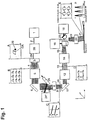
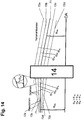
- Fig. 1 shows an exemplary embodiment of a processing device according to the invention for laser processing of a surface 23.
- the processing apparatus here has a laser system 1 which emits a collimated laser beam 2.
- the laser can be, for example, an unpulsed (cw laser), a short-pulse laser, for example a nanosecond laser, or preferably an ultrashort-pulsed laser, for example a picosecond laser and / or a femtosecond laser, which emits light of high coherence.
- cw laser unpulsed
- a short-pulse laser for example a nanosecond laser
- ultrashort-pulsed laser for example a picosecond laser and / or a femtosecond laser
- the wavelength of the laser can be, for example, in the infrared range, for example at 1064 nm or 1030 nm, in the visible range, for example at 532 nm or 515 nm, or else in the ultraviolet range, for example at 355 nm or 348 nm.
- the diameter of the emitted beam 2 is to be denoted by d 0 .
- the exemplary processing device of Fig. 1 has a rotational unit 28 arranged downstream of the laser system in the beam direction, by means of which the laser beam can be displaced parallel to the optical axis in an offset direction by a distance greater than zero, the offset direction circulating in time around the optical axis.
- That area between the laser system 1 and the rotation unit 28 is referred to herein as a laser beam input, at which the laser beam in a beam direction on an optical axis in the rotation unit or the processing device can be irradiated.
- the rotation unit 28 generates a parallel beam offset relative to the optical axis in the stationary state.
- the distance between the staggered beam (or its main beam) and the optical axis should be denoted by r .
- the collimated laser beam has a diameter of d 1 when hitting the rotating unit.
- the beam 29 leaves the rotation unit 28 collimated and thus moves in this example on a circular path parallel to the optical axis, as shown in Part A of the Fig. 1 is shown, which forms a section perpendicular to the optical axis.
- the rotation unit can advantageously be a rotating plane parallel plate of thickness t , which can be driven by a hollow shaft motor.
- a surface normal relative to the axis of rotation is tilted by an angle ⁇ , which is preferably not equal to 0 ° and not equal to 90 °.
- the motor allows rotation of the parallelepiped plate at a high speed in the range of, for example, 50-100 Hz or higher.
- the beam offset can also be realized, for example, by a combination of at least two synchronously rotating wedge plates (anamorphic prisms) which can be adjusted in relation to one another.
- Further possibilities for inducing the rotating optical beam offset are, for example, the use of a rotating Schmidt-Pechan prism, a rotating K-mirror or a rotating Dove prism. It is also possible to variably realize the radius r around which the laser beam 29 is offset with respect to the optical axis. This is possible with more complex structures.
- the processing device of Fig. 1 also has a divergence unit 3 arranged in the beam direction behind the rotation unit, with which the laser beam can be fanned into a plurality of partial beam 4, which can have a continuous or discrete intensity distribution in the direction radially to the optical axis.
- the main beam can be divided into a finite or infinite number of new main beams, each differing in their direction relative to the optical axis.
- a new main beam forms along with this set of rays a sub-beam. The divergence unit thus leads to a change in the intensity distribution of the incident laser beam in the angular space.
- a continuous intensity distribution is advantageously a coherent intensity distribution, which is formed by the divergence unit.
- each sub-beam in the sense of paraxial geometric optics can be focused in a point on a common focal plane with orientation perpendicular to the optical axis.
- the generation of the letter "F” may be mentioned.
- the contiguous intensity distribution of the "F” is formed by the divergence unit.
- an intensity distribution with the shape of the letter "F” is generated in the focal plane of the first module.
- Each point in the intensity distribution is shaped by a single sub-beam.
- An example of a discontinuous intensity distribution is a beam splitter (e.g., a split into a 4 by 4 sub-beam grid) which splits the laser beam into a finite number of sub-beams. Focusing in the focal plane of the first module results in locally separated focus points in an image of the paraxial optics. In an image of the diffraction-limited optics focus areas are created in the focal plane.
- a beam splitter e.g., a split into a 4 by 4 sub-beam grid
- a combination of continuous intensity distribution and discontinuous intensity distribution by the divergence unit can also be done.
- the formation of a grid of 4 by 4 areas may be mentioned, each forming an "F".
- the divergence unit 3 can be, for example, a beam splitter 3.
- the divergence unit or units 3 may be rotatably mounted, preferably in three dimensions.
- the divergence unit may be a diffractive optical element having a pattern of microstructures.
- the divergence unit 3 divides the laser beam 29 into a total beam 4 of partial beams.
- the distribution of these partial beams is determined by the construction of the divergence unit 3.
- the divergence unit can also generate any intensity distribution.
- n is the integer order of the grating
- ⁇ is the wavelength of the laser beam
- g is the grating pitch
- ⁇ n is the angle of the sub-beam to the optical axis.
- two-dimensional grids of the intensity distribution or complex intensity distributions can be produced.
- DOE diffractive optical element
- P n describes the power of the partial beam n
- ⁇ efficiency of the beam splitter
- P 0 the power of the incoming laser beam 29
- N and M the highest orders of the beam splitter
- ⁇ p n individual fluctuations in the power of the partial beam due to production- related inhomogeneities of the beam splitter.
- unwanted higher diffraction orders can also occur in the case of a beam splitter 3. These can also be part of the total beam 4.
- the total beam 4 of collimated sub-beams or the intensity distribution set by the beam splitter also performs a rotational movement by the rotation of the laser beam 29, as shown in sub-figure B, which depicts a plane perpendicular to the optical axis. This rotational movement can be transmitted in this example further optical beam path.
- a first module 5 which may be referred to as a relay module 5, on, with which the plurality of partial beam 4 to each other in an overall beam extending parallel to the beam direction can be parallelized.
- the entirety of the partial beam leaving the module 5 is referred to as the total beam.
- the beam directions of these partial beam bundles are behind the first module 5 parallel to each other.
- the relay module 5 may also cause focusing of the sub-beams, so that each sub-beam is focused in a plane 10, the plane 10 is preferably the same for all sub-beams and is perpendicular to the optical axis.
- processing device has in the beam direction behind the first module 5 on a beam deflector 6, which may be a simple mirror here.
- the beam deflector 6 is arranged with its surface normal at an angle of 45 ° to the optical axis and therefore causes a deflection of the partial beam through an angle of 90 °. It should always be assumed here that the optical axis and the beam direction are deflected by the corresponding angle by such a beam deflector, so that the optical axis in the example shown behind the beam deflector 6 at an angle of 90 ° to the optical axis in front of the beam deflector 6 stands.
- the processing apparatus shown has, in the beam direction behind the beam deflector 6, a selection unit which has a mirror 24 on the one hand and a mask 8 on the other hand. A part of the partial beam bundles of the total beam can be removed by the selection unit.
- the mirror 24 is oriented such that it reflects part of the partial beam bundle incident along the beam direction into an absorber 24 *.
- the mirror 24 is designed to be movable and thereby retractable into the beam path of some partial beam.
- the remaining partial beam bundles 7 * of the total beam then hit the mask 8, which removes further partial beam bundles from the remaining total beam 7 *.
- the mask 8 zeroth and higher diffraction orders can be removed from the total beam 7 * when the divergence unit 3 is based on a grating.
- the mask 8 may comprise a metal sheet, a coated transparent substrate in which a non-transparent coating has suitable openings, or a mirror with a defined grid of holes be that propagate the desired main orders uninfluenced.
- the zeroth and higher orders to be selected may be absorbed by the mask 8 or deflected into an absorber, for example the beam absorber 24 *.
- the selection unit is arranged in a region along the optical axis in which the partial beam bundles of the overall beam do not overlap. This can be achieved in particular in that the first module 5 focuses the partial beam bundles on the plane 10 in each case. As a result, the partial beam bundles do not overlap in an area in front of and behind the plane 10. Accordingly, the selection unit with the mirror 24 and the mask 8 can be arranged in this area.
- Subfigure C in Fig. 1 shows that the rotation of the individual partial beam is transmitted to the plane 10.
- a further beam deflector 11 is arranged, which in turn is with its surface normal at an angle of 45 ° to the optical axis and thus deflects the sub-beam as well as the optical axis and the beam direction by 90 °.
- the in Fig. 1 processing device shown an optional zoom system 12, with which the distance between the sub-beam of the total beam is changeable.
- the zoom system 12 thus scales the total beam 9 of the sub-beam passing through the mask 8 by a fixed, discrete or continuous adjustment and thus allows a change in the spot distances, in the case of any intensity distribution scaling this intensity distribution.
- the zoom system may include, for example, interchangeable fixed focal length lenses, moving lenses with discrete or continuous positions, or active elements such as liquid lenses, and preferably being motorized.
- the zoom system is alternatively positioned at an arbitrary position between the divergence unit 3 and the focusing unit 20 may be or may be an integral part of one of the devices and lens groups in this area.
- the processing device of Fig. 1 has in the beam direction behind the zoom system 12 on another module 14, which may be referred to as a second relay module 14.
- a second relay module 14 With this second module, the partial beams 9, which emerge from the zoom system 12 in parallel directions, converge, so that they have a minimal distance from one another in a beam plane 25. If the partial beam bundles are respectively focused onto the plane 10 by the first module 5, then they can each impinge divergently on the second relay module 14. This is advantageous when the module 14 collimates the partial beam.
- the second module 14 may be arranged in its orientation with respect to the optical axis exactly opposite to the first module 5, so that both together image the beam splitter 3 in the beam plane 25.
- the beam axes of the partial beam bundles of the total beam 15 emerging from the second module 14 can intersect.
- the processing device of Fig. 1 also has a deflecting unit arranged behind the second module in the beam direction, which has the beam deflectors 16 and 18 here.
- the deflection unit is arranged so that the effective point, by which the beams are deflected, lies in the beam plane 25.
- the beam deflectors 16 and 18 allow an adjustable deflection of the laser beam with high dynamics in the working plane of the workpiece 23.
- the beam deflectors are arranged perpendicular to each other here, so that they allow a beam deflection in two spatial directions.
- the beam deflector may be a galvanometer scanner here.
- other dynamic beam deflectors such as polygon scanners, resonance scanners, piezo scanners, MEM mirrors, acousto-optical or electro-optical deflectors can be used.
- the processing device shown has a focusing unit 20 with which the remaining partial beam bundles 19 of the total beam s can be parallelized. If the second module 14 in each case collimates the partial beam bundles, the focusing unit 20 can also focus the partial beam bundles in each case into the plane to be processed, so that the focusing unit has a Focusing optics 20 is.
- the focusing optics may, for example, be an F-theta-corrected lens with telecentric properties. Together with the beam deflectors 16 and 18, the resulting foci can then be deflected on any two-dimensional paths on the workpiece 23.
- the rotation of the beam offset caused by the rotation unit 28 leads in the beam plane 25 to a movement of the partial beam on a circular path with the radius r '.
- the beam offset leads to an adjustment of the laser beam relative to the optical axis of the focusing optics, so that the laser beam at an angle ⁇ relative to the optical axis hits the workpiece, as shown in part of Figure F of Fig. 1 is shown.
- the focused and adjusted total beam 21 forms on the workpiece 23 a determined by the beam splitter and the rest of the processing optics intensity distribution.
- a grid of foci in the form of grid points with equidistant grid point spacings in the respective spatial direction can be created in the working plane 23.
- the scaling of the total beam 13 by the zoom unit 12 allows a change of the grid point distances in the working plane 23 with high accuracy.
- a process gas nozzle is introduced between the focusing unit 20 and the workpiece 23, which directs a gas jet to the processing points and can lead to a targeted discharge of liquid or gaseous material.
- the process gas nozzle can be designed so that it has a plurality of partial nozzles, each covering the working area of a partial beam.
- a collimated laser beam 2 is emitted from the laser system 1 and subsequently impinges on a rotation unit 28 which induces a beam offset r such that the laser beam bundle describes a circular orbit about the optical system axis (cf. Fig. 1 - Picture A).
- the collimated laser beam then passes through a diffractive optical element (DOE).
- DOE diffractive optical element
- the rotation of the diffractive optical element relative to the optical axis is preferably set so that the edges of the rectangle which comprises the beam distribution of the DOE are each parallel to one of the scanner axes of the beam deflection units 16 or 18 are aligned.
- the bundle 4 encounters a relay module 5 which focuses the beam on the plane 10.
- the beam selection module preferably has two movable axes and a rectangular mirror which deflects subregions of the total beam 7 into the beam absorber 24 * by moving the axes.
- the beam 7 * strikes a mask 8 behind the beam selection module 24.
- the mask 8 selects further partial beam bundles from the total beam 7 * and thus filters unwanted higher orders, for example for the process. Behind the mask 8, the cleaned total beam 9 exits, whose partial beam are focused by focusing in the relay module 5 in the beam plane 10.
- the beam 9 is coupled into the zoom system 12.
- the zoom system 12 scales the total beam 9 with the aim of spatially manipulating the distances of the individual sub-beams on the workpiece 23.
- the total beam 13 enters the second relay module 14, so that a scaled image of the beam splitter 3 in the effective axis of rotation 25 of the dynamic beam deflector consisting of the elements 16 and 18 takes place.
- the deflected by the beam deflectors 16 and 18 total beam 19 is focused by the focusing optics 20 on the workpiece 23.
- the focused total beam 21 forms on the workpiece 23 a determined by the beam splitter and the rest of the processing optics intensity distribution.
- the rotation of the complete partial beam on the workpiece 23 is thereby manipulated by the rotation of the beam splitter 3 about the axis of the beam propagation direction (optical axis).
- the adjustment of the laser beam relative to the optical axis of the focusing unit is effected by the beam offset r of the rotation unit 28.
- the dynamic beam deflectors 16 and 18 are moved so that a circular path with fixed rotational frequency on the workpiece 23 is traversed (see. Fig. 1 - Picture E). This circular path is carried out by each partial beam.
- the rotation unit 28 is preferably moved synchronously with the beam deflectors 16 and 18 so that the rotational frequency of the rotation unit 28 and the circular path coincide. This results in the laser beam forming a constant angle of attack with each tangent of the circular path.
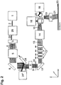
- Fig. 2 shows a further exemplary embodiment of a processing device according to the invention for laser processing of a surface 23rd
- the zoom system 12 is realized by way of example by means of four rotationally symmetrical lenses, which are displaceable relative to one another along the optical axis.
- a collimated laser beam 2 is emitted from the laser system 1 and subsequently impinges on a rotation unit 28 which induces a beam offset r so that the laser beam describes a circular orbit about the optical system axis.
- the collimated laser beam then passes through a beam splitter 3.
- the beam splitter splits the laser beam bundle 29 into a bundle 4 of respectively collimated partial beam bundles.
- the bundle 4 encounters a relay module 5 which focuses the beam on the plane 10.
- the focused total beam 7 passes through an area in which the partial beam are spatially separated.
- 24 selected rays are filtered by means of dynamically positionable beam selection module and deflected to a beam absorber 24 *.
- the beam 7 * strikes a mask 8 behind the beam selection module 24.
- the mask 8 selects further partial beam bundles from the total beam 7 * and thus filters unwanted higher orders, for example for the process.
- Behind the mask 8 the cleaned total beam 9 exits, whose partial beam are focused by focusing in the relay module 5 in the beam plane 10.
- the beam 9 is coupled into a 4-lens zoom system 12.
- the zoom system 12 influences the spatial angular distribution of the individual beams and thus scales the total beam 9 to form total beams 13 with the aim of spatially manipulating the distances of the individual partial beams on the workpiece 23.
- lenses defined in the zoom 12 are dynamically moved to model-based predefined positions in order to achieve the necessary magnification.
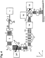
- Fig. 3 shows a further exemplary embodiment of a processing device according to the invention. Again, the elements shown correspond to those in FIG Fig. 1 shown, so that the statements made there are transferable. It is in Fig. 3 However, the zoom system by means of two anamorphic prism pairs 26 and 27, ie with wedge plate pairs 26 and 27 realized.
- a collimated laser beam 2 is emitted from the laser system 1 and subsequently impinges on a rotation unit 28, which induces a beam offset r so that the laser beam describes a circular path.
- the collimated laser beam then passes through a beam splitter 3.
- the beam splitter splits the laser beam bundle 29 into a bundle 4 of respectively collimated partial beam bundles.
- the bundle 4 encounters an anamorphic prism pair 26 which serves as a zoom system.
- the angular distribution in one axis can be manipulated and thus a change of the beam separation on the workpiece 23 in the affected axis can be achieved.
- the manipulated bundle strikes the relay module 5, which focuses the beam on the plane 10.
- the focused total beam 7 passes through an area in which the partial beam are spatially separated.
- 24 selected beam bundles are filtered by means of dynamically positionable beam selection module and deflected to a beam absorber 24 *.
- the beam 7 * strikes a mask 8 behind the beam selection module 24.
- the mask 8 selects further partial beam bundles from the total beam 7 * and thus filters unwanted higher orders, for example for the process.
- the beam 9 is coupled into a second anamorphic prism pair 27, which is arranged perpendicular to the first pair of prisms 26 and thus manipulates the second spatial axis of the beam spacings on the workpiece 23.
- the total beam 13 enters the second relay module 14, so that a scaled image of the beam splitter 3 in the effective axis of rotation 25 of the dynamic beam deflector consisting of the elements 16 and 18 takes place.
- the deflected by the beam deflectors 16 and 18 total beam 19 is focused by the focusing optics 20 on the workpiece 23.
- the focused total beam 21 forms on the workpiece 23 through the beam splitter and the rest of the processing optics determined intensity distribution.
- the rotation of the partial beam in the working plane on the workpiece 23 is thereby manipulated via the rotation of the beam splitter 3 orthogonal to the beam propagation direction.
- Fig. 4 shows a further embodiment of a processing device according to the invention.
- the elements shown essentially correspond to those in FIG Fig. 1 shown.
- the description too Fig. 1 can therefore up Fig. 4 be transmitted.
- the rotation unit 28 is designed as a tilted plane parallel plate and the zoom device 12 by means of four lenses which are displaceable relative to one another along the optical axis.
- a beam offset is induced in accordance with the refractive law.
- the beam 29 leaves the plate parallel and collimates to the optical axis.
- the rotation of the plane parallel plate causes the staggered beam to rotate about the optical axis and thus performs a circular motion.
- the angle of attack of the plane parallel plate relative to the optical axis can also be zero. In this case, however, the offset would be zero.
- Fig. 5 shows a further exemplary embodiment of the processing device according to the invention.
- the elements shown correspond to those in FIG Fig. 1 shown, so the description too Fig. 1 on Fig. 5 is transferable.
- the divergence unit 3 is tiltable relative to the optical axis.
- it may be a diffractive optical element.
- the period of the partial beam arrangement in the workpiece plane 23 can be influenced. This can be used, for example, for a fine adjustment of the spot period in the resolution range of a few micrometers to the range of a few nanometers.
- Fig. 6 shows a further embodiment of a processing device according to the invention.
- the structure corresponds to that in Fig. 1 shown, so the description too Fig. 1 on Fig. 6 is transferable.
- the in Fig. 6 shown construction a Lichtpolarisationstechnik 30 which changes the polarization state of the laser beam spatially dynamic.
- the light polarization unit 30 is arranged between the laser system 1 and the rotation unit 28.
- a linearly polarized collimated laser beam 2 is emitted from the laser system 1 and subsequently impinges on the light polarization unit 30 spatially, dynamically changes the polarization state of the laser beam.
- the Lichtpolarisationsaku 30 may have different versions. In the preferred case, it consists of a rotatably mounted half-wave plate which can perform a rotation of the polarization direction about the optical axis. The half-wave plate can be rotated at high frequency about the optical axis, so that a fast rotation of the polarization direction of the linearly polarized laser is made possible. Preferably, the rotation frequency of the half-wave plate is exactly half as large as that of the rotation unit 28.
- the polarization-modified laser beam 31 leaves the polarization unit 30 and subsequently strikes the rotation unit 28, which induces a beam offset r so that the laser beam describes a circular path.
- the collimated laser beam then passes through a beam splitter 3.
- the beam splitter divides the laser beam 29 into a bundle 4 of respectively collimated partial beams.
- the bundle 4 encounters a relay module 5 which focuses the beam on the plane 10.
- the focused total beam 7 passes through an area in which the partial beam bundles are spatially separated.
- 24 selected rays are filtered by means of dynamically positionable beam selection module and deflected to a beam absorber 24 *.
- the beam 7 * strikes a mask 8 behind the beam selection module 24.
- the mask 8 selects further partial beam bundles from the total beam 7 * and thus filters unwanted higher orders, for example for the process.
- the cleaned total beam 9 exits, whose partial beam are focused by focusing in the relay module 5 in the beam plane 10.
- the beam 9 is coupled into the zoom system 12.
- the zoom system 12 scales the total beam 9 with the aim of spatially manipulating the distances of the individual sub-beams on the workpiece 23.
- the total beam 13 enters the second relay module 14, so that a scaled image of the beam splitter 3 in the effective axis of rotation 25 of the dynamic beam deflector consisting of the elements 16 and 18 takes place.
- the deflected by the dynamic beam deflectors 16 and 18 total beam 19 is focused by the focusing optics 20 on the workpiece 23.
- the focused total beam 21 forms on the workpiece 23 a determined by the beam splitter and the rest of the processing optics intensity distribution.
- the rotation of the partial beam on the workpiece 23 is thereby manipulated via the rotation of the beam splitter 3 orthogonal to the beam propagation direction.
- the polarization unit can also be made of a quarter-wave plate for making circular polarization or a combination of retardation plates for producing other types of polarization.
- These include preferably the production of radial polarization in which the polarization vectors are radially aligned with the center of the intensity distribution of the laser beam or tangential polarization in which the polarization vectors are tangent to the center of the intensity distribution by using segmented quarter wave or half wave plates.
- Fig. 7 shows an exemplary realization of a rotation unit 28, with which an incident laser beam 2 is displaceable parallel by an amount r, wherein the embodiment shown allows to adjust the distance r variable.
- the structure has a first mirror 28a which reflects the incident laser beam 2 onto a plane-parallel plate 28b.
- the laser beam passes through the plane-parallel plate 28b and is offset parallel to its direction of incidence.
- the exiting laser beam strikes a second mirror 28c, which is oriented so that the outgoing laser beam 29 is parallel to the incident laser beam 2, but offset by the amount r.
- the plane parallel plate 28b is designed to rotate.
- the plane-parallel plate 28b rotates about an axis that passes through the point of impact of the laser beam on the plane-parallel plate.
- the angle of incidence ⁇ of the laser beam on the plane-parallel plate 28b can be adjusted. This is due to the plane parallel plate as in Fig. 1 described defined beam offset and thus a circular path radius r, which is variable by the change of the angle of incidence.
- the two mirrors are always correspondingly symmetrically adjusted so that the point of impact of the laser beam on the plane parallel plate corresponds to the rotation axis of the rotation unit and that the axis of rotation of the rotating beam after reflection on the second mirror 28c is identical for all angle settings.
- FIG. 8 shows by way of example a structure of a zoom unit having a first group of cylindrical lenses 12a and a second group of cylindrical lenses 12 b, which are arranged between the first module 5 and the second module 14.
- the cylinder axes of the cylindrical lenses are rotated in the lenses of the second group 12b with respect to the lenses of the first group 12a by 90 ° about the optical axis.
- the distance between the sub-beams is scaled in a first direction perpendicular to the optical axis and by the cylindrical lenses of the second groups 12b, a distance of the sub-beam is scaled in a direction perpendicular to the first direction.
- FIG. 9 illustrates the optical mode of action of anamorphic prisms on a discontinuous beam distribution.
- FIG. 9 shows this displacement of the partial beam 93 for three different exemplary positions of the prisms 91 and 92, which lead to different angles ⁇ 2 and ⁇ 3 and thus to different shifts in the focal plane 10 by distances d 2 and d 3rd
- the focus points in the focal plane 10 are the focus points in the focal plane 10. It can be seen that are caused by the tilting of the prisms 91 and 92 different distances between the focus points in one dimension.
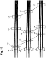
- FIG. 10 shows the course of the beams of three different sub-beam through a zoom system 12, which is formed with four rotationally symmetric lenses L4, L5, L6 and L7, in different configurations of the individual lens positions. It can be seen that the spacing of the partial beams 7a, 7b and 7c at the output of the four lenses L4, L5, L6 and L7 depends on the positioning of these lenses relative to each other. In the upper part of the figure FIG. 10 have the sub-beam 7a, 7b and 7c at the output of the smallest distance to each other. In the lowest part of the figure they have the greatest distance to each other.
- the partial beams 7a, 7b and 7c are shown as a bundle of a plurality of beams.
- One of these rays can be considered the main ray.
- the zoom system then scales the distances of the main beams to each other.
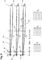
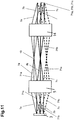
- FIG. 11 shows simplified the beam path of three different partial beam from the divergence unit 3 via the first module 5 to behind the second module 14 in a structure without zoom system.
- the divergence unit 3 fans out a laser beam not shown in the example shown into three partial beams 7a, 7b and 7c.
- Each sub-beam has a plurality of beams, of which in FIG. 11 in each case a main beam 71a, 71b and 71c and two further beams are shown by way of example.
- the divergence unit 3 collimated so that all the beams of the sub-beams each parallel to the respective main beam 71a, 71b and 71c.
- the beams run parallel to the main beam 71a, while they run parallel to the main beam 71b in the partial beam 7b.
- the first module 5 reduces the angles of the main beams 71a, 71b, and 71c relative to one another. In FIG. 11 this leads to a parallelization of the main beams 71a, 71b and 71c.
- the first module 5 focuses the partial beams 7a, 7b and 7c respectively.
- the partial beam bundles in each case again run apart and meet divergently on the second module 14. This colimates in the example shown, the partial beam, respectively, so that each sub-beam is collimated.
- the second module 14 deflects the sub-beam so that the main beams 71a, 71b and 71c of the sub-beam converge towards each other and at the right end of the in FIG. 11 cut construction shown.
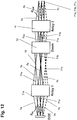
- FIG. 12 shows a structure similar to that in FIG. 11 shown, but additionally has a zoom system 12. It can be seen that the zoom system 12 changes the distance of the main beams 71a, 71b and 71c from each other, in the example shown reduced. The other elements of the device according to the invention were in FIG. 12 omitted for clarity.
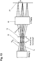
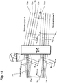
- FIG. 13 11 shows an illustration of the preferred positioning of the deflection unit 16 and 18 in a preferred configuration with a galvanometer scanner having two dynamically movable mirrors 16 and 18 in the area behind the second module 14.
- the mirrors 16 and 18 of the deflection unit are positioned so that the point where the main beams intersect due to the deflection by the second module 14 is just midway between the mirrors 16 and 18. *** "
- the partial beam bundles 7a, 7b and 7c after being deflected by the mirrors 16 and 18, pass through the focus unit 20, which here is an F-Linse lens.
- the focus unit 20 focuses the partial steel bundles respectively on the surface 23 to be processed.
- FIG. 14 shows a definition of the angles between the beams 72a, 72b, 72c and 72d relative to a main beam 71 and the effect of the second module 14 on the angles of the beams 72a, 72b, 72c and 72d in the sub-beam and relative to the angle of the main beam 71 to the optical axis.
- the sub-beam 7 passes at an angle of its main beam ⁇ HA with respect to the optical axis OA on the first module 14.
- the second module 14 changes the angle of the main beam to the optical axis in the angle ⁇ HB is smaller than the angle ⁇ HA in the example shown ,
- the angle of the beam 72a to the main beam 71 is designated by ⁇ 3a , the angle of the beam 72b to the main beam 71 by ⁇ 2a and the angle of the beam 72c to the main beam 71 by ⁇ 1a .
- the first module 14 reduces the angles of the beams 72a, 72b, 72c and 72d to the main beam 71, respectively, so that the angles of the outgoing beams ⁇ 1b , ⁇ 2b and ⁇ 3b are each smaller than the angle of the incident beam to the incident principal beam ⁇ 1a , ⁇ 2a and ⁇ 3a .
- FIG. 15 shows the in FIG. 14 illustrated effect of the second module on the beams and in addition to the angle between main beams of different partial beam. Regarding the effect on the angles of the rays to the corresponding main ray on FIG. 14 directed.
- the principal ray of the upper sub-beam 7a will be referred to as 71a and the main ray of the lower sub-beam 7b as 71b.
- the main beams 71a and 71b make an angle ⁇ H1-H2-A slightly converging toward the second module 14. By the second module 14, they are deflected towards each other, so that they run towards each other behind the second module 14 with an angle ⁇ H1-H2-B .
- FIG. 16 shows a scanning strategy for the production of periodic patterns with the device according to the invention.
- the interspaces of adjacent sub-beam bundles are filled with structures.
- the period of the structures is an integer divisor of the spot period, that is to say the period of the partial beam bundles on the processing surface 23.
- the pattern of the processing points (Laserfoki) at a distance of the spot period is thereby moved by the deflection unit along a scan contour and thus generates a structure. Thereafter, the pattern is offset by a first period of the structures along a first axial direction, and the pattern is moved again with the deflection unit along the same scan contour. This is carried out until the area along the first axial direction with the length of the spot period has been filled with structures. This results in a closed row of periodic structures. Subsequently, the pattern is offset by a second period of the structures along a second axial direction, which is perpendicular to the first axial direction, by the deflection unit. Again, the pattern with the deflector is moved along the scan contour and the next row of structures is created by the procedure already described. This strategy is according to FIG. 16 until a closed area of periodic structures has been created.
- FIG. 17 shows a possible beam path for the image of a continuous Intensity distribution.
- the image consists of an infinite number of pixels, the distance between adjacent points ⁇ X being infinitely small.
- Each pixel can be assigned a partial beam.
- there are infinitely many sub-beam bundles whose main beams differ in their direction only by an infinitesimal angle ⁇ .
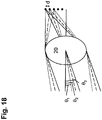
- FIG. 18 shows a possible beam path for the imaging of a discontinuous intensity distribution.
- the image consists of a finite number of pixels with a spatial separation d> 0.
- d a spatial separation
- the main rays of the sub-beams differ in their direction by angles other than zero.
Landscapes
- Physics & Mathematics (AREA)
- Optics & Photonics (AREA)
- Engineering & Computer Science (AREA)
- Plasma & Fusion (AREA)
- Mechanical Engineering (AREA)
- General Physics & Mathematics (AREA)
- Laser Beam Processing (AREA)
- Mechanical Optical Scanning Systems (AREA)
Applications Claiming Priority (2)
| Application Number | Priority Date | Filing Date | Title |
|---|---|---|---|
| DE201410200633 DE102014200633B3 (de) | 2014-01-15 | 2014-01-15 | Bearbeitungsvorrichtung und -verfahren zur Laserbearbeitung einer Oberfläche |
| PCT/EP2015/050489 WO2015107044A1 (de) | 2014-01-15 | 2015-01-13 | Bearbeitungsvorrichtung und -verfahren zur laserbearbeitung einer oberfläche |
Publications (2)
| Publication Number | Publication Date |
|---|---|
| EP3094444A1 EP3094444A1 (de) | 2016-11-23 |
| EP3094444B1 true EP3094444B1 (de) | 2019-07-31 |
Family
ID=52358769
Family Applications (1)
| Application Number | Title | Priority Date | Filing Date |
|---|---|---|---|
| EP15700558.8A Active EP3094444B1 (de) | 2014-01-15 | 2015-01-13 | Bearbeitungsvorrichtung und -verfahren zur laserbearbeitung einer oberfläche |
Country Status (8)
| Country | Link |
|---|---|
| EP (1) | EP3094444B1 (enExample) |
| JP (1) | JP6430523B2 (enExample) |
| KR (1) | KR102132846B1 (enExample) |
| CN (1) | CN106102982B (enExample) |
| DE (1) | DE102014200633B3 (enExample) |
| DK (1) | DK3094444T3 (enExample) |
| ES (1) | ES2751474T3 (enExample) |
| WO (1) | WO2015107044A1 (enExample) |
Cited By (1)
| Publication number | Priority date | Publication date | Assignee | Title |
|---|---|---|---|---|
| EP4238685A4 (en) * | 2020-10-28 | 2024-09-18 | Nikon Corporation | Optical processing device |
Families Citing this family (46)
| Publication number | Priority date | Publication date | Assignee | Title |
|---|---|---|---|---|
| DE102015213897A1 (de) * | 2015-07-23 | 2017-01-26 | Fraunhofer-Gesellschaft zur Förderung der angewandten Forschung e.V. | Anordnung und Verfahren zur verzeichnungsfreien zweidimensionalen Ablenkung von räumlich ausgedehnten Intensitätsverteilungen |
| DE102016112176B4 (de) * | 2016-07-04 | 2021-08-12 | Precitec Gmbh & Co. Kg | Vorrichtung zum selektiven Einführen einer Optik in einen Laserstrahl eines Laserbearbeitungskopfes und Laserbearbeitungskopf mit derselben |
| DE112017003592T5 (de) * | 2016-07-15 | 2019-03-28 | TeraDiode, Inc. | Materialbearbeitung unter Verwendung eines Lasers mit variabler Strahlform |
| EP3309520B1 (de) * | 2016-10-17 | 2018-08-29 | SICK STEGMANN GmbH | Winkelmesssystem zum bestimmen eines drehwinkels |
| CN107322171A (zh) * | 2016-12-08 | 2017-11-07 | 中国航空工业集团公司北京长城计量测试技术研究所 | 一种利用超短脉冲激光的复合加工系统 |
| CN106735875B (zh) * | 2017-02-20 | 2019-01-18 | 湖北工业大学 | 一种基于液晶空间光调制器的激光柔性微加工系统及方法 |
| CN106825918A (zh) * | 2017-03-13 | 2017-06-13 | 浙江师范大学 | 一种混合式激光束扫描装置及控制方法 |
| CN106695118B (zh) * | 2017-03-13 | 2018-10-09 | 浙江师范大学 | 一种四自由度xy振镜扫描装置及控制方法 |
| DE102017105955A1 (de) * | 2017-03-20 | 2018-09-20 | Laserpluss Ag | Laserschleifvorrichtung sowie Verfahren zum Bearbeiten eines Werkstückes |
| EP3385770A1 (en) * | 2017-04-07 | 2018-10-10 | Universite Paris Descartes | Spatio-temporal wavefront shaping of optical beams |
| CN107498052B (zh) * | 2017-09-22 | 2019-03-05 | 华中科技大学 | 一种用于多激光slm成形装置的负载均衡扫描成形方法 |
| SG11202001217RA (en) * | 2017-09-22 | 2020-03-30 | Electro Scientific Industries Inc | Acousto-optic system having phase-shifting reflector |
| DE102017217069A1 (de) | 2017-09-26 | 2019-03-28 | Volkswagen Aktiengesellschaft | Rotationseinheit für eine Beschichtungslanzeneinrichtung zum thermischen Beschichten eines Innenraums, sowie eine solche Beschichtungslanzeneinrichtung |
| CN108526685A (zh) * | 2018-07-06 | 2018-09-14 | 温州大学激光与光电智能制造研究院 | 激光加工光路分光系统 |
| BE1026484B1 (fr) * | 2018-07-24 | 2020-02-25 | Laser Eng Applications | Méthode et dispositif optique pour fournir deux faisceaux laser décalés |
| DE102018220434A1 (de) * | 2018-11-28 | 2020-05-28 | Fraunhofer-Gesellschaft zur Förderung der angewandten Forschung e.V. | Optische Anordnung zur Strukturierung von Oberflächen eines Substrates |
| CN109865939A (zh) * | 2019-01-22 | 2019-06-11 | 华东师范大学 | 一种双飞秒激光束柱透镜汇聚干涉制备大面积周期微纳结构的装置 |
| TWI843784B (zh) * | 2019-01-31 | 2024-06-01 | 美商伊雷克托科學工業股份有限公司 | 雷射加工設備、與設備一起使用的控制器及非暫時性電腦可讀取媒體 |
| DE202019101652U1 (de) | 2019-03-22 | 2019-05-16 | 4Jet Microtech Gmbh | Laserbearbeitungsvorrichtung zum Erzeugen einer Vielzahl von Furchen |
| DE102019108131A1 (de) * | 2019-03-28 | 2020-10-01 | Pulsar Photonics Gmbh | Vorrichtung und Verfahren zur Ausbildung von VIA-Laserbohrungen |
| DE102019114191A1 (de) * | 2019-05-27 | 2020-12-03 | Pulsar Photonics Gmbh | Laserbearbeitungsvorrichtung und Verfahren zur gleichzeitigen und selektiven Bearbeitung einer Mehrzahl von Bearbeitungsstellen eines Werkstücks |
| CN110543090B (zh) * | 2019-08-16 | 2022-01-28 | 北京钛极科技有限公司 | 一种光学加工系统及光学加工方法 |
| TWI716126B (zh) * | 2019-09-27 | 2021-01-11 | 財團法人工業技術研究院 | 雷射半切加工方法及其裝置 |
| JP7443041B2 (ja) * | 2019-12-12 | 2024-03-05 | 東レエンジニアリング株式会社 | 光スポット像照射装置および転写装置 |
| JP7443042B2 (ja) * | 2019-12-12 | 2024-03-05 | 東レエンジニアリング株式会社 | 光スポット像照射装置および転写装置 |
| BE1027700B1 (fr) | 2020-04-24 | 2021-05-18 | Laser Eng Applications | Dispositif pour un système optique d’usinage laser |
| BE1028021B1 (fr) * | 2020-06-30 | 2021-08-23 | Laser Eng Applications | Dispositif optique pour le marquage de pièces transparentes |
| CN112059412A (zh) * | 2020-07-30 | 2020-12-11 | 华东师范大学 | 一种激光诱导自由曲面周期性纳米结构图案与着色方法 |
| CN112045303B (zh) * | 2020-08-25 | 2021-12-17 | 之江实验室 | 基于光纤的高通量超分辨焦斑生成装置 |
| CN112192030B (zh) * | 2020-09-07 | 2021-07-27 | 中国科学院西安光学精密机械研究所 | 一种阵列增透减反功能的微纳结构加工方法及系统 |
| US20230390866A1 (en) * | 2020-12-08 | 2023-12-07 | Electro Scientific Industries, Inc. | Optical relay system and methods of use and manufacture |
| US11733534B2 (en) | 2021-01-21 | 2023-08-22 | AdlOptica Optical Systems GmbH | Optics for formation of multiple light spots with controlled spot intensity and variable spot pattern geometry |
| CN113319425B (zh) * | 2021-05-14 | 2022-08-05 | 华中科技大学 | 一种多轴激光扫描光学系统 |
| DE102021205500A1 (de) * | 2021-05-31 | 2022-12-01 | Volkswagen Aktiengesellschaft | Verfahren zur Herstellung einer Batterieelektrode |
| JP7647433B2 (ja) * | 2021-08-10 | 2025-03-18 | 株式会社リコー | レーザーマーキング装置 |
| CN114888458B (zh) * | 2021-08-17 | 2023-12-15 | 武汉华工激光工程有限责任公司 | 一种并行旋切加工装置及方法 |
| DE102021124004A1 (de) | 2021-09-16 | 2023-03-16 | Joachim Kern | Vorrichtung und Verfahren zur Herstellung von Düsenscheiben für Vernebler |
| CN114178677B (zh) * | 2021-12-09 | 2022-09-13 | 中国科学院西安光学精密机械研究所 | 一种微结构激光加工头、加工系统及调试加工方法 |
| DE102022134959A1 (de) * | 2022-12-29 | 2024-07-04 | Fraunhofer-Gesellschaft zur Förderung der angewandten Forschung eingetragener Verein | Verfahren zum laserbasierten Materialabtrag mit definiertem Kantenwinkel |
| DE102023102170A1 (de) * | 2023-01-30 | 2024-08-01 | Trumpf Laser Gmbh | Vorrichtung und Verfahren zum Bearbeiten eines Werkstücks |
| CN116560098A (zh) * | 2023-04-05 | 2023-08-08 | 无锡奥普顿光电子有限公司 | 一种光束分束平行输出装置 |
| WO2025056103A1 (de) | 2023-09-13 | 2025-03-20 | Nebu-Tec Med. Produkte Eike Kern Gmbh | Herstellung von verbesserten düsenscheiben durch laserbearbeitung |
| CN117239527B (zh) * | 2023-11-14 | 2024-04-12 | 拉普拉斯新能源科技股份有限公司 | 一种激光装置、激光加工系统及加工方法 |
| DE102023133294A1 (de) * | 2023-11-28 | 2025-05-28 | Trumpf Laser Gmbh | Vorrichtung und Verfahren zum Bearbeiten eines Werkstücks |
| DE102024001157B4 (de) * | 2024-04-11 | 2025-09-04 | Mercedes-Benz Group AG | Verfahren zur Formung eines Laserstrahles für eine Materialbearbeitung |
| DE102024117459A1 (de) * | 2024-06-20 | 2025-12-24 | Jenoptik Optical Systems Gmbh | Optische Anordnung zur Laserprojektion, Vorrichtung zur Laserbearbeitung und Verwendung derselben |
Family Cites Families (13)
| Publication number | Priority date | Publication date | Assignee | Title |
|---|---|---|---|---|
| FR2585480B1 (fr) * | 1985-07-24 | 1994-01-07 | Ateq Corp | Generateur de modeles a laser |
| US5386221A (en) * | 1992-11-02 | 1995-01-31 | Etec Systems, Inc. | Laser pattern generation apparatus |
| US5463200A (en) * | 1993-02-11 | 1995-10-31 | Lumonics Inc. | Marking of a workpiece by light energy |
| JP3271055B2 (ja) * | 1997-07-14 | 2002-04-02 | 住友重機械工業株式会社 | レーザによる光学材料のマーキング方法及びマーキング装置 |
| JP2000280225A (ja) * | 1999-04-02 | 2000-10-10 | Murata Mfg Co Ltd | セラミックグリーンシートの加工方法及び加工装置 |
| US6606197B2 (en) * | 2000-03-28 | 2003-08-12 | Corning Incorporated | Dual grating filtering system |
| US20040017431A1 (en) * | 2002-07-23 | 2004-01-29 | Yosuke Mizuyama | Laser processing method and laser processing apparatus using ultra-short pulse laser |
| US7521651B2 (en) * | 2003-09-12 | 2009-04-21 | Orbotech Ltd | Multiple beam micro-machining system and method |
| JP4184288B2 (ja) * | 2004-01-20 | 2008-11-19 | 日立ビアメカニクス株式会社 | レーザ加工機 |
| DE102007032231A1 (de) * | 2007-07-11 | 2009-01-15 | 3D-Micromac Ag | Vorrichtung zur Erzeugung von Mikrolöchern |
| CN201529849U (zh) * | 2009-10-09 | 2010-07-21 | 廊坊昊博金刚石有限公司 | 激光双面同步加工系统 |
| JP5511644B2 (ja) * | 2010-12-07 | 2014-06-04 | 住友重機械工業株式会社 | レーザ加工装置及びレーザ加工方法 |
| JP5148730B2 (ja) * | 2011-05-18 | 2013-02-20 | 昭和オプトロニクス株式会社 | ファイバ転送レーザ光学系 |
-
2014
- 2014-01-15 DE DE201410200633 patent/DE102014200633B3/de not_active Expired - Fee Related
-
2015
- 2015-01-13 KR KR1020167021946A patent/KR102132846B1/ko active Active
- 2015-01-13 CN CN201580014382.6A patent/CN106102982B/zh active Active
- 2015-01-13 WO PCT/EP2015/050489 patent/WO2015107044A1/de not_active Ceased
- 2015-01-13 DK DK15700558T patent/DK3094444T3/da active
- 2015-01-13 ES ES15700558T patent/ES2751474T3/es active Active
- 2015-01-13 JP JP2016546429A patent/JP6430523B2/ja active Active
- 2015-01-13 EP EP15700558.8A patent/EP3094444B1/de active Active
Non-Patent Citations (1)
| Title |
|---|
| None * |
Cited By (1)
| Publication number | Priority date | Publication date | Assignee | Title |
|---|---|---|---|---|
| EP4238685A4 (en) * | 2020-10-28 | 2024-09-18 | Nikon Corporation | Optical processing device |
Also Published As
| Publication number | Publication date |
|---|---|
| CN106102982A (zh) | 2016-11-09 |
| WO2015107044A1 (de) | 2015-07-23 |
| KR102132846B1 (ko) | 2020-07-13 |
| EP3094444A1 (de) | 2016-11-23 |
| JP2017504483A (ja) | 2017-02-09 |
| DE102014200633B3 (de) | 2015-05-07 |
| DK3094444T3 (da) | 2019-11-04 |
| ES2751474T3 (es) | 2020-03-31 |
| KR20160107298A (ko) | 2016-09-13 |
| CN106102982B (zh) | 2018-09-25 |
| JP6430523B2 (ja) | 2018-11-28 |
Similar Documents
| Publication | Publication Date | Title |
|---|---|---|
| EP3094444B1 (de) | Bearbeitungsvorrichtung und -verfahren zur laserbearbeitung einer oberfläche | |
| EP3799999B1 (de) | Optisches system zur strahlformung | |
| EP3221727B1 (de) | System zur asymmetrischen optischen strahlformung | |
| EP2976176B1 (de) | Verfahren und anordnung zur ausbildung einer strukturierung an oberflächen von bauteilen mit einem laserstrahl | |
| DE102014116958B4 (de) | Optisches System zur Strahlformung eines Laserstrahls, Laserbearbeitungsanlage, Verfahren zur Materialbearbeitung und Verwenden einer gemeinsamen langgezogenen Fokuszone zur Lasermaterialbearbeitung | |
| EP2596899B1 (de) | Vorrichtung und Verfahren zur Interferenzstrukturierung von flächigen Proben | |
| DE102015216342B3 (de) | Technik zur Herstellung periodischer Strukturen | |
| EP2217961A1 (de) | Vorrichtung zur strahlformung | |
| DE102020102077B4 (de) | Laserbearbeitungsvorrichtung und Verfahren zur Laserbearbeitung eines Werkstücks | |
| DE102012011343A1 (de) | Vorrichtung und Verfahren zur Interferenzstrukturierung von Proben sowie dergestalt strukturierte Proben | |
| DE102008016011A1 (de) | Korrektur optischer Elemente mittels flach eingestrahltem Korrekturlicht | |
| DE102020107760A1 (de) | Laserbearbeitungsvorrichtung und Verfahren zur Laserbearbeitung eines Werkstücks | |
| DE102021101373A1 (de) | Anordnung zur Lasermaterialbearbeitung | |
| WO2021151925A1 (de) | Laserbearbeitungsvorrichtung und verfahren zur laserbearbeitung eines werkstücks | |
| DE102015200795B3 (de) | Anordnung zur Bestrahlung einer Objektfläche mit mehreren Teilstrahlen ultrakurz gepulster Laserstrahlung | |
| DE102020134367A1 (de) | Vorrichtung zum Bearbeiten eines Materials | |
| DE10233491A1 (de) | Kompakte Einrichtung zur Bebilderung einer Druckform | |
| EP4263118A1 (de) | Vorrichtung zur strahlbeeinflussung eines laserstrahls | |
| WO2022033923A1 (de) | Vorrichtung zum erzeugen einer definierten laserlinie auf einer arbeitsebene | |
| DE102016124408A1 (de) | Vorrichtung zur Ablenkung und/oder Modulation einer Laserstrahlung, insbesondere einer Mehrzahl von Laserstrahlen | |
| DE102023102170A1 (de) | Vorrichtung und Verfahren zum Bearbeiten eines Werkstücks | |
| DE102022125106A1 (de) | Optische Anordnung für eine Laserbearbeitungsanlage | |
| WO1999028077A2 (de) | Vorrichtung zur homogenisierung eines licht- oder laserstrahls | |
| WO2025045517A1 (de) | Vorrichtung zum erzeugen einer periodischen struktur in einer substratfläche eines substrats und verfahren zu deren betrieb | |
| WO2024160647A1 (de) | Vorrichtung und verfahren zum bearbeiten eines werkstücks |
Legal Events
| Date | Code | Title | Description |
|---|---|---|---|
| PUAI | Public reference made under article 153(3) epc to a published international application that has entered the european phase |
Free format text: ORIGINAL CODE: 0009012 |
|
| 17P | Request for examination filed |
Effective date: 20160812 |
|
| AK | Designated contracting states |
Kind code of ref document: A1 Designated state(s): AL AT BE BG CH CY CZ DE DK EE ES FI FR GB GR HR HU IE IS IT LI LT LU LV MC MK MT NL NO PL PT RO RS SE SI SK SM TR |
|
| AX | Request for extension of the european patent |
Extension state: BA ME |
|
| RIN1 | Information on inventor provided before grant (corrected) |
Inventor name: GATEJ, ALEXANDER Inventor name: EIFEL, STEPHAN Inventor name: HOLTKAMP, JENS Inventor name: GILLNER, ARNOLD Inventor name: BUESING, LASSE Inventor name: TRAUB, MARTIN Inventor name: RYLL, JOACHIM Inventor name: GRETZKI, PATRICK |
|
| DAX | Request for extension of the european patent (deleted) | ||
| GRAP | Despatch of communication of intention to grant a patent |
Free format text: ORIGINAL CODE: EPIDOSNIGR1 |
|
| STAA | Information on the status of an ep patent application or granted ep patent |
Free format text: STATUS: GRANT OF PATENT IS INTENDED |
|
| INTG | Intention to grant announced |
Effective date: 20190314 |
|
| GRAS | Grant fee paid |
Free format text: ORIGINAL CODE: EPIDOSNIGR3 |
|
| GRAA | (expected) grant |
Free format text: ORIGINAL CODE: 0009210 |
|
| STAA | Information on the status of an ep patent application or granted ep patent |
Free format text: STATUS: THE PATENT HAS BEEN GRANTED |
|
| AK | Designated contracting states |
Kind code of ref document: B1 Designated state(s): AL AT BE BG CH CY CZ DE DK EE ES FI FR GB GR HR HU IE IS IT LI LT LU LV MC MK MT NL NO PL PT RO RS SE SI SK SM TR |
|
| REG | Reference to a national code |
Ref country code: CH Ref legal event code: EP Ref country code: GB Ref legal event code: FG4D Free format text: NOT ENGLISH |
|
| REG | Reference to a national code |
Ref country code: AT Ref legal event code: REF Ref document number: 1160403 Country of ref document: AT Kind code of ref document: T Effective date: 20190815 |
|
| REG | Reference to a national code |
Ref country code: IE Ref legal event code: FG4D Free format text: LANGUAGE OF EP DOCUMENT: GERMAN |
|
| REG | Reference to a national code |
Ref country code: DE Ref legal event code: R096 Ref document number: 502015009809 Country of ref document: DE |
|
| REG | Reference to a national code |
Ref country code: DK Ref legal event code: T3 Effective date: 20191029 |
|
| REG | Reference to a national code |
Ref country code: SE Ref legal event code: TRGR |
|
| REG | Reference to a national code |
Ref country code: NL Ref legal event code: MP Effective date: 20190731 |
|
| REG | Reference to a national code |
Ref country code: LT Ref legal event code: MG4D |
|
| PG25 | Lapsed in a contracting state [announced via postgrant information from national office to epo] |
Ref country code: BG Free format text: LAPSE BECAUSE OF FAILURE TO SUBMIT A TRANSLATION OF THE DESCRIPTION OR TO PAY THE FEE WITHIN THE PRESCRIBED TIME-LIMIT Effective date: 20191031 Ref country code: NL Free format text: LAPSE BECAUSE OF FAILURE TO SUBMIT A TRANSLATION OF THE DESCRIPTION OR TO PAY THE FEE WITHIN THE PRESCRIBED TIME-LIMIT Effective date: 20190731 Ref country code: LT Free format text: LAPSE BECAUSE OF FAILURE TO SUBMIT A TRANSLATION OF THE DESCRIPTION OR TO PAY THE FEE WITHIN THE PRESCRIBED TIME-LIMIT Effective date: 20190731 Ref country code: HR Free format text: LAPSE BECAUSE OF FAILURE TO SUBMIT A TRANSLATION OF THE DESCRIPTION OR TO PAY THE FEE WITHIN THE PRESCRIBED TIME-LIMIT Effective date: 20190731 Ref country code: PT Free format text: LAPSE BECAUSE OF FAILURE TO SUBMIT A TRANSLATION OF THE DESCRIPTION OR TO PAY THE FEE WITHIN THE PRESCRIBED TIME-LIMIT Effective date: 20191202 Ref country code: FI Free format text: LAPSE BECAUSE OF FAILURE TO SUBMIT A TRANSLATION OF THE DESCRIPTION OR TO PAY THE FEE WITHIN THE PRESCRIBED TIME-LIMIT Effective date: 20190731 Ref country code: NO Free format text: LAPSE BECAUSE OF FAILURE TO SUBMIT A TRANSLATION OF THE DESCRIPTION OR TO PAY THE FEE WITHIN THE PRESCRIBED TIME-LIMIT Effective date: 20191031 |
|
| PG25 | Lapsed in a contracting state [announced via postgrant information from national office to epo] |
Ref country code: LV Free format text: LAPSE BECAUSE OF FAILURE TO SUBMIT A TRANSLATION OF THE DESCRIPTION OR TO PAY THE FEE WITHIN THE PRESCRIBED TIME-LIMIT Effective date: 20190731 Ref country code: GR Free format text: LAPSE BECAUSE OF FAILURE TO SUBMIT A TRANSLATION OF THE DESCRIPTION OR TO PAY THE FEE WITHIN THE PRESCRIBED TIME-LIMIT Effective date: 20191101 Ref country code: RS Free format text: LAPSE BECAUSE OF FAILURE TO SUBMIT A TRANSLATION OF THE DESCRIPTION OR TO PAY THE FEE WITHIN THE PRESCRIBED TIME-LIMIT Effective date: 20190731 Ref country code: AL Free format text: LAPSE BECAUSE OF FAILURE TO SUBMIT A TRANSLATION OF THE DESCRIPTION OR TO PAY THE FEE WITHIN THE PRESCRIBED TIME-LIMIT Effective date: 20190731 Ref country code: IS Free format text: LAPSE BECAUSE OF FAILURE TO SUBMIT A TRANSLATION OF THE DESCRIPTION OR TO PAY THE FEE WITHIN THE PRESCRIBED TIME-LIMIT Effective date: 20191130 |
|
| PG25 | Lapsed in a contracting state [announced via postgrant information from national office to epo] |
Ref country code: TR Free format text: LAPSE BECAUSE OF FAILURE TO SUBMIT A TRANSLATION OF THE DESCRIPTION OR TO PAY THE FEE WITHIN THE PRESCRIBED TIME-LIMIT Effective date: 20190731 |
|
| REG | Reference to a national code |
Ref country code: ES Ref legal event code: FG2A Ref document number: 2751474 Country of ref document: ES Kind code of ref document: T3 Effective date: 20200331 |
|
| PG25 | Lapsed in a contracting state [announced via postgrant information from national office to epo] |
Ref country code: RO Free format text: LAPSE BECAUSE OF FAILURE TO SUBMIT A TRANSLATION OF THE DESCRIPTION OR TO PAY THE FEE WITHIN THE PRESCRIBED TIME-LIMIT Effective date: 20190731 Ref country code: EE Free format text: LAPSE BECAUSE OF FAILURE TO SUBMIT A TRANSLATION OF THE DESCRIPTION OR TO PAY THE FEE WITHIN THE PRESCRIBED TIME-LIMIT Effective date: 20190731 Ref country code: PL Free format text: LAPSE BECAUSE OF FAILURE TO SUBMIT A TRANSLATION OF THE DESCRIPTION OR TO PAY THE FEE WITHIN THE PRESCRIBED TIME-LIMIT Effective date: 20190731 |
|
| PG25 | Lapsed in a contracting state [announced via postgrant information from national office to epo] |
Ref country code: IS Free format text: LAPSE BECAUSE OF FAILURE TO SUBMIT A TRANSLATION OF THE DESCRIPTION OR TO PAY THE FEE WITHIN THE PRESCRIBED TIME-LIMIT Effective date: 20200224 Ref country code: SK Free format text: LAPSE BECAUSE OF FAILURE TO SUBMIT A TRANSLATION OF THE DESCRIPTION OR TO PAY THE FEE WITHIN THE PRESCRIBED TIME-LIMIT Effective date: 20190731 Ref country code: SM Free format text: LAPSE BECAUSE OF FAILURE TO SUBMIT A TRANSLATION OF THE DESCRIPTION OR TO PAY THE FEE WITHIN THE PRESCRIBED TIME-LIMIT Effective date: 20190731 Ref country code: CZ Free format text: LAPSE BECAUSE OF FAILURE TO SUBMIT A TRANSLATION OF THE DESCRIPTION OR TO PAY THE FEE WITHIN THE PRESCRIBED TIME-LIMIT Effective date: 20190731 |
|
| REG | Reference to a national code |
Ref country code: DE Ref legal event code: R097 Ref document number: 502015009809 Country of ref document: DE |
|
| PLBE | No opposition filed within time limit |
Free format text: ORIGINAL CODE: 0009261 |
|
| STAA | Information on the status of an ep patent application or granted ep patent |
Free format text: STATUS: NO OPPOSITION FILED WITHIN TIME LIMIT |
|
| PG2D | Information on lapse in contracting state deleted |
Ref country code: IS |
|
| PG25 | Lapsed in a contracting state [announced via postgrant information from national office to epo] |
Ref country code: IS Free format text: LAPSE BECAUSE OF FAILURE TO SUBMIT A TRANSLATION OF THE DESCRIPTION OR TO PAY THE FEE WITHIN THE PRESCRIBED TIME-LIMIT Effective date: 20191030 |
|
| 26N | No opposition filed |
Effective date: 20200603 |
|
| PG25 | Lapsed in a contracting state [announced via postgrant information from national office to epo] |
Ref country code: SI Free format text: LAPSE BECAUSE OF FAILURE TO SUBMIT A TRANSLATION OF THE DESCRIPTION OR TO PAY THE FEE WITHIN THE PRESCRIBED TIME-LIMIT Effective date: 20190731 Ref country code: MC Free format text: LAPSE BECAUSE OF FAILURE TO SUBMIT A TRANSLATION OF THE DESCRIPTION OR TO PAY THE FEE WITHIN THE PRESCRIBED TIME-LIMIT Effective date: 20190731 |
|
| REG | Reference to a national code |
Ref country code: BE Ref legal event code: MM Effective date: 20200131 |
|
| PG25 | Lapsed in a contracting state [announced via postgrant information from national office to epo] |
Ref country code: LU Free format text: LAPSE BECAUSE OF NON-PAYMENT OF DUE FEES Effective date: 20200113 |
|
| PG25 | Lapsed in a contracting state [announced via postgrant information from national office to epo] |
Ref country code: BE Free format text: LAPSE BECAUSE OF NON-PAYMENT OF DUE FEES Effective date: 20200131 |
|
| PG25 | Lapsed in a contracting state [announced via postgrant information from national office to epo] |
Ref country code: IE Free format text: LAPSE BECAUSE OF NON-PAYMENT OF DUE FEES Effective date: 20200113 |
|
| PG25 | Lapsed in a contracting state [announced via postgrant information from national office to epo] |
Ref country code: MT Free format text: LAPSE BECAUSE OF FAILURE TO SUBMIT A TRANSLATION OF THE DESCRIPTION OR TO PAY THE FEE WITHIN THE PRESCRIBED TIME-LIMIT Effective date: 20190731 Ref country code: CY Free format text: LAPSE BECAUSE OF FAILURE TO SUBMIT A TRANSLATION OF THE DESCRIPTION OR TO PAY THE FEE WITHIN THE PRESCRIBED TIME-LIMIT Effective date: 20190731 |
|
| PG25 | Lapsed in a contracting state [announced via postgrant information from national office to epo] |
Ref country code: MK Free format text: LAPSE BECAUSE OF FAILURE TO SUBMIT A TRANSLATION OF THE DESCRIPTION OR TO PAY THE FEE WITHIN THE PRESCRIBED TIME-LIMIT Effective date: 20190731 |
|
| P01 | Opt-out of the competence of the unified patent court (upc) registered |
Effective date: 20230524 |
|
| PGFP | Annual fee paid to national office [announced via postgrant information from national office to epo] |
Ref country code: ES Payment date: 20240216 Year of fee payment: 10 |
|
| PGFP | Annual fee paid to national office [announced via postgrant information from national office to epo] |
Ref country code: AT Payment date: 20240118 Year of fee payment: 10 |
|
| PGFP | Annual fee paid to national office [announced via postgrant information from national office to epo] |
Ref country code: SE Payment date: 20240123 Year of fee payment: 10 Ref country code: IT Payment date: 20240131 Year of fee payment: 10 Ref country code: DK Payment date: 20240123 Year of fee payment: 10 |
|
| PGFP | Annual fee paid to national office [announced via postgrant information from national office to epo] |
Ref country code: DE Payment date: 20250120 Year of fee payment: 11 |
|
| PGFP | Annual fee paid to national office [announced via postgrant information from national office to epo] |
Ref country code: CH Payment date: 20250201 Year of fee payment: 11 |
|
| PGFP | Annual fee paid to national office [announced via postgrant information from national office to epo] |
Ref country code: FR Payment date: 20250122 Year of fee payment: 11 |
|
| PGFP | Annual fee paid to national office [announced via postgrant information from national office to epo] |
Ref country code: GB Payment date: 20250123 Year of fee payment: 11 |
|
| REG | Reference to a national code |
Ref country code: DK Ref legal event code: EBP Effective date: 20250131 |
|
| REG | Reference to a national code |
Ref country code: SE Ref legal event code: EUG |
|
| REG | Reference to a national code |
Ref country code: AT Ref legal event code: MM01 Ref document number: 1160403 Country of ref document: AT Kind code of ref document: T Effective date: 20250113 |
|
| PG25 | Lapsed in a contracting state [announced via postgrant information from national office to epo] |
Ref country code: AT Free format text: LAPSE BECAUSE OF NON-PAYMENT OF DUE FEES Effective date: 20250113 |