EP3093922A1 - Kontaktelement für erdung einer mastleuchte - Google Patents
Kontaktelement für erdung einer mastleuchte Download PDFInfo
- Publication number
- EP3093922A1 EP3093922A1 EP16169415.3A EP16169415A EP3093922A1 EP 3093922 A1 EP3093922 A1 EP 3093922A1 EP 16169415 A EP16169415 A EP 16169415A EP 3093922 A1 EP3093922 A1 EP 3093922A1
- Authority
- EP
- European Patent Office
- Prior art keywords
- contact element
- luminaire
- leg
- mast
- housing
- Prior art date
- Legal status (The legal status is an assumption and is not a legal conclusion. Google has not performed a legal analysis and makes no representation as to the accuracy of the status listed.)
- Granted
Links
Images
Classifications
-
- H—ELECTRICITY
- H01—ELECTRIC ELEMENTS
- H01R—ELECTRICALLY-CONDUCTIVE CONNECTIONS; STRUCTURAL ASSOCIATIONS OF A PLURALITY OF MUTUALLY-INSULATED ELECTRICAL CONNECTING ELEMENTS; COUPLING DEVICES; CURRENT COLLECTORS
- H01R4/00—Electrically-conductive connections between two or more conductive members in direct contact, i.e. touching one another; Means for effecting or maintaining such contact; Electrically-conductive connections having two or more spaced connecting locations for conductors and using contact members penetrating insulation
- H01R4/26—Connections in which at least one of the connecting parts has projections which bite into or engage the other connecting part in order to improve the contact
-
- H—ELECTRICITY
- H01—ELECTRIC ELEMENTS
- H01R—ELECTRICALLY-CONDUCTIVE CONNECTIONS; STRUCTURAL ASSOCIATIONS OF A PLURALITY OF MUTUALLY-INSULATED ELECTRICAL CONNECTING ELEMENTS; COUPLING DEVICES; CURRENT COLLECTORS
- H01R4/00—Electrically-conductive connections between two or more conductive members in direct contact, i.e. touching one another; Means for effecting or maintaining such contact; Electrically-conductive connections having two or more spaced connecting locations for conductors and using contact members penetrating insulation
- H01R4/58—Electrically-conductive connections between two or more conductive members in direct contact, i.e. touching one another; Means for effecting or maintaining such contact; Electrically-conductive connections having two or more spaced connecting locations for conductors and using contact members penetrating insulation characterised by the form or material of the contacting members
- H01R4/64—Connections between or with conductive parts having primarily a non-electric function, e.g. frame, casing, rail
-
- F—MECHANICAL ENGINEERING; LIGHTING; HEATING; WEAPONS; BLASTING
- F21—LIGHTING
- F21V—FUNCTIONAL FEATURES OR DETAILS OF LIGHTING DEVICES OR SYSTEMS THEREOF; STRUCTURAL COMBINATIONS OF LIGHTING DEVICES WITH OTHER ARTICLES, NOT OTHERWISE PROVIDED FOR
- F21V21/00—Supporting, suspending, or attaching arrangements for lighting devices; Hand grips
- F21V21/10—Pendants, arms, or standards; Fixing lighting devices to pendants, arms, or standards
-
- F—MECHANICAL ENGINEERING; LIGHTING; HEATING; WEAPONS; BLASTING
- F21—LIGHTING
- F21V—FUNCTIONAL FEATURES OR DETAILS OF LIGHTING DEVICES OR SYSTEMS THEREOF; STRUCTURAL COMBINATIONS OF LIGHTING DEVICES WITH OTHER ARTICLES, NOT OTHERWISE PROVIDED FOR
- F21V23/00—Arrangement of electric circuit elements in or on lighting devices
Definitions
- the present invention relates to a contact element for producing a grounding connection for a pole luminaire.
- Mast lights usually include a metallic housing and / or a metallic mast flange, which is also referred to as a housing in the context of this description, which requires a potential equalization to ground for safety reasons.
- a metallic housing and / or a metallic mast flange which is also referred to as a housing in the context of this description, which requires a potential equalization to ground for safety reasons.
- equipotential bonding to earth can be achieved simply by making electrical contact with the metallic pole.
- the material of the mast is made of a non-conductor, e.g. Concrete, plastic or wood, separate equipment for the formation of equipotential bonding to earth are necessary.
- the object is achieved by a contact element according to claim 1 and by a pole lamp according to claim 7.
- the contact element according to the invention offers the possibility for light poles of different wall thickness to a simple electrical contact with the lamp housing create.
- any parts of the lamp housing or attached to the lamp housing flange eg articulated understood in general, which are adapted to be placed on a lamppost.
- the contact element has a U-shaped portion which is formed of a spring steel, so that it is suitable for different wall thicknesses of the lamp housing to be plugged thereon.
- a separate grounding conductor is connected as a single core to a first contact area.
- a second electrical contact area is provided which forms the electrical contact with the lamp housing by simply placing it. It is therefore simply plugged the contact element according to the invention on the lamppost and connected a separate grounding before placing the lamp housing. After placing the lamp housing, an electrical contact between the lamp housing and the earth is then formed for potential equalization.
- the second contact region has one, preferably two outwardly pointing, sharp-edged tongues, which are set up to scratch the attached luminaire housing.
- the sharp-edged tongues can form an electrical contact with the metallic core of the housing through a color or insulation layer of the luminaire housing.
- the tongues may, according to a preferred embodiment, be formed by simply bending one or two corners of the spring steel sheet. Alternatively, the tongues can also be formed by a cutout, which is bent upwards away from the lamp post. Under a tongue in this context, any shape, in particular triangular or square shapes with sharp corners to understand. It is particularly advantageous to provide two oppositely directed tongues, so that when the lamp housing is screwed tightly on a side opposite the contact element, the tongues dig against one another in the material of the lamp housing.
- the first contact region has an opening or a terminal, to which the grounding conductor can be connected as a separate individual line.
- a simple opening as a contact area is enough to clamp the earthing conductor.
- a clamp is provided on the contact element itself to form the first contact region.
- a barb pointing towards the wall of the luminaire mast is provided on the first and / or second leg, which prevents a movement of the contact element against the mounting direction.
- the contact element also remains firmly connected to the luminaire mast when the luminaire housing is removed from the mast for assembly work.
- the barb is formed by an inwardly angled portion of the first or second leg, i.e., the spring steel sheet itself. In this way, the barb is particularly easy to produce.
- An aspect of the invention also relates to a mast luminaire having a luminaire mast of a non-conductive material and a contact element according to an embodiment as described above, and an attached luminaire housing which forms an electrical contact with the contact element.
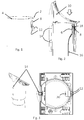
- the contact element is bent in a U-shape, so that a first leg 6 of the contact element 2 has in the interior of the lamp post 4 and a second leg 8 is located on the outside of the lamp post.
- the lamp housing 10 in the present embodiment comprises the lower part of a mast flange on which another part of the lamp housing is pivotally mounted (the upper part of the lamp housing is not shown in the figures).
- the second leg 8 of the contact element has at the lower two corners each a tongue which is outwardly, i. away from the luminaire mast 4, are angled.
- the tongues 12 are sharp-edged in the region of the edges and the corner, so that they dig into this when plugging the lamp housing 10. In particular, they also penetrate an optionally existing insulation or color layer of the lamp housing in order to make electrical contact with the metallic core of the lamp housing 10.
- a grounding cable 16 is connected in an opening 20 of the first leg 6, which serves to contact element 2 on a base of the mast with the Connect the earth electrically. In this way, an electrical potential equalization between the lamp housing 10 and the earth is created.
- the contact element 2 therefore provides a particularly simple way to create an electrical tap for grounding the lamp housing 10.
- the contact element 2 is attached to the lamp post before assembly of the lamp housing 10 and connected to the grounding conductor 16. Without further precautions after mounting and screwing the lamp housing 10, the electrical connection to the lamp housing is formed.
- a barb 18 is further formed by a bent inward toward the wall of the lamp post 4 portion of the spring steel sheet. This barb 18 digs when plugging the contact element 2 in the wall of the lamp post 4, so that an unintentional release of the contact element is prevented even when removing the lamp housing 10 for assembly work.
Landscapes
- Non-Portable Lighting Devices Or Systems Thereof (AREA)
- Fastening Of Light Sources Or Lamp Holders (AREA)
Abstract
Description
- Die vorliegende Erfindung betrifft ein Kontaktelement zur Herstellung eines Erdungsanschlusses für eine Mastleuchte.
- Mastleuchten umfassen in der Regel ein metallisches Gehäuse und/oder einen metallischen Mastflansch, welcher im Rahmen dieser Beschreibung ebenfalls als Gehäuse bezeichnet wird, das bzw. der aus Sicherheitsgründen einen Potenzialausgleich zur Erde benötigt. Für Leuchten, die auf einem metallischen Leuchtenmast montiert werden, kann der Potenzialausgleich zur Erde einfach durch einen elektrischen Kontakt zu dem metallischen Mast erfolgen. Sofern jedoch das Material des Masts aus einem Nichtleiter besteht, z.B. Beton, Kunststoff oder Holz, sind separate Einrichtungen zur Bildung des Potenzialausgleichs zur Erde notwendig.
- Für nichtleitende Leuchtenmasten ist daher eine zusätzliche elektrische Verbindung notwendig, um das Leuchtengehäuse mit der Erde zu verbinden. Eine zusätzliche Ader ist in den standardisierten Kabelsträngen zum Anschluss der Leuchten in der Regel jedoch nicht vorgesehen. Insbesondere darf der gelb/grüne Leiter der Anschlussleitung nicht für die Erdung verwendet werden, da diese Farbbezeichnung nur für den Schutzleiter verwendet werden darf. Es war daher notwendig, eine zusätzliche Ader in den Kabelstrang einzuführen. Diese Lösung ist äußerst aufwendig, da die standardgemäßen Anschlussleitungen getauscht werden müssen. Außerdem muss ein Ablegepunkt an der Leuchte geschaffen werden.
- Die vorliegende Erfindung soll eine technisch einfache Möglichkeit bieten, um einem Erdungsleiter innerhalb eines Leuchtenmastes mit dem Leuchtengehäuse elektrisch zu verbinden.
- Gelöst wird die Aufgabe durch ein Kontaktelement nach Anspruch 1 sowie durch eine Mastleuchte nach Anspruch 7.
- Das erfindungsgemäße Kontaktelement bietet die Möglichkeit für Leuchtenmasten unterschiedlicher Wandstärke einen einfachen elektrischen Kontakt zu dem Leuchtengehäuse zu schaffen. Unter Leuchtengehäuse gemäß der vorliegenden Beschreibung werden allgemein auch beliebige Teile des Leuchtengehäuses oder eines an dem Leuchtengehäuse angebrachten Flansches (z.B. gelenkig verbunden) verstanden, die dafür eingerichtet sind, auf einen Leuchtenmast aufgesetzt zu werden.
- Das Kontaktelement besitzt einen U-förmigen Abschnitt, der aus einem Federstahl gebildet ist, so dass er sich für unterschiedliche Wandstärken des Leuchtengehäuses eignet, um darauf aufgesteckt zu werden. Auf dem Schenkel des U-förmigen Abschnitts des Kontaktelements, der in den Leuchtenmast weist, wird ein separater Erdungsleiter als Einzelader an einem ersten Kontaktbereich angeschlossen. Auf dem zweiten gegenüberliegenden Schenkel, welcher auf der Außenseite des Leuchtenmastes liegt, ist ein zweiter elektrischer Kontaktbereich vorgesehen, welcher den elektrischen Kontakt zu dem Leuchtengehäuse durch einfaches Aufsetzen von diesem bildet. Es wird daher vor dem Aufsetzen des Leuchtengehäuses einfach das erfindungsgemäße Kontaktelement auf den Leuchtenmast aufgesteckt und eine separate Erdungsleitung angeschlossen. Nach dem Aufsetzen des Leuchtengehäuses ist dann ein elektrischer Kontakt zwischen dem Leuchtengehäuse und der Erde zum Potenzialausgleich gebildet.
- Gemäß einer bevorzugten Ausführungsform weist der zweite Kontaktbereich eine, vorzugsweise zwei nach außen weisende scharfkantige Zungen auf, welche dafür eingerichtet sind, das aufgesetzte Leuchtengehäuse anzukratzen. Die scharfkantigen Zungen können durch eine Farb- oder Isolierungsschicht des Leuchtengehäuses hindurch einen elektrischen Kontakt zu dem metallischen Kern des Gehäuses bilden.
- Die Zungen können gemäß einer bevorzugten Ausführungsform durch einfaches Abbiegen von einer oder zwei Ecken des Federstahlblechs gebildet werden. Alternativ können die Zungen auch durch einen Ausschnitt gebildet werden, der nach außen vom Leuchtenmast weg aufgebogen ist. Unter einer Zunge ist in diesem Zusammenhang jede beliebige Form, insbesondere dreieckige oder viereckige Formen mit scharfkantigen Ecken zu verstehen. Es ist von besonderem Vorteil, zwei gegeneinander gerichtete Zungen vorzusehen, so dass bei einem Festschrauben des Leuchtengehäuses auf einer dem Kontaktelement gegenüberliegenden Seite die Zungen sich gegeneinander in das Material des Leuchtengehäuses eingraben.
- Gemäß einer bevorzugen Ausführungsform weist der erste Kontaktbereich eine Öffnung oder eine Klemme auf, an welcher der Erdungsleiter als separate Einzelleitung anschließbar ist.
- Eine einfache Öffnung als Kontaktbereich genügt, um den Erdungsleiter festzuklemmen. Gemäß einer Alternative ist eine Klemme an dem Kontaktelement selbst vorgesehen, um den ersten Kontaktbereich zu bilden.
- Gemäß einer bevorzugten Ausführungsform ist an dem ersten und/oder zweiten Schenkel ein zur Wand des Leuchtenmastes weisender Widerhaken vorgesehen, der ein Abrücken des Kontaktelements entgegen der Aufsteckrichtung verhindert. Dadurch bleibt das Kontaktelement auch mit dem Leuchtenmast fest verbunden, wenn das Leuchtengehäuse von dem Mast zu Montagearbeiten abgenommen wird.
- Gemäß einer bevorzugten Ausführungsform ist der Widerhaken durch einen nach innen abgewinkelten Abschnitt des ersten oder zweiten Schenkel, d.h., aus dem Federstahlblech selbst, gebildet. Auf diese Weise ist der Widerhaken besonders einfach herstellbar.
- Ein Aspekt der Erfindung bezieht sich auch auf eine Mastleuchte mit einem Leuchtenmast aus einem nichtleitenden Material und einem Kontaktelement gemäß einer Ausführungsform wie vorhergehend beschrieben, und einem aufgesetzten Leuchtengehäuse, das einen elektrischen Kontakt mit dem Kontaktelement bildet.
- Weitere Vorteile und Merkmale der vorliegenden Erfindung werden aus der nachfolgenden Beschreibung einer bevorzugten Ausführungsform deutlich, die in Verbindung mit den Figuren gegeben wird, in denen Folgendes dargestellt ist:
- Figur 1
- zeigt eine perspektivische Ansicht eines oberen Leuchtenmastabschnittes mit aufgestecktem Kontaktelement gemäß einer Ausführungsform.
- Figur 2
- zeigt einen Querschnitt durch den oberen Mastabschnitt gemäß
Figur 1 mit einem aufgesetzten Leuchtengehäuse und einer angeschlossenen Erdungsleitung. - Figur 3
- zeigt eine Aufsicht auf das Leuchtengehäuse gemäß
Figur 2 , wobei im Piktogramm eine perspektivische Ansicht des Mastabschnitts mit dem Leuchtengehäuse gezeigt ist. - Bezugnehmend auf
Figur 1 ist ein aus Federstahlblech bestehendes Kontaktelement 2 dargestellt, welches auf einem Rand eines hohlen Leuchtenmastes 4 aufgesteckt ist. Der Leuchtenmast 4 ist aus einem nichtleitenden Material, wie z.B. aus Kunststoff, Holz oder Beton, gebildet. - Wie in dem Querschnitt gemäß
Figur 2 zu sehen ist, ist das Kontaktelement U-förmig gebogen, so dass ein erster Schenkel 6 des Kontaktelements 2 in den Innenraum des Leuchtenmastes 4 weist und ein zweiter Schenkel 8 auf der Außenseite des Leuchtenmastes liegt. - Über den Leuchtenmast 4 mit darauf aufgestecktem Kontaktelement 2 ist ein Leuchtengehäuse 10 aufgeschoben, wie in
Figur 2 mit der Aufsteckrichtung durch den Pfeil dargestellt ist. Das Leuchtengehäuse 10 in der vorliegenden Ausführungsform umfasst den unteren Teil eines Mastflansches, auf welchen ein weiterer Teil des Leuchtengehäuses schwenkbar montiert ist (der obere Teil des Leuchtengehäuses ist in den Figuren nicht dargestellt). - Der zweite Schenkel 8 des Kontaktelements weist an den unteren beiden Ecken jeweils eine Zunge auf, die nach außen, d.h. vom Leuchtenmast 4 weg, abgewinkelt sind. Die Zungen 12 sind im Bereich der Kanten und der Ecke scharfkantig ausgebildet, so dass sie sich beim Aufstecken des Leuchtengehäuses 10 in dieses eingraben. Insbesondere durchdringen sie auch eine gegebenenfalls vorhandene Isolierungs- oder Farbschicht des Leuchtengehäuses, um einen elektrischen Kontakt mit dem metallischen Kern des Leuchtengehäuses 10 einzugehen.
- Auf der dem Kontaktelement 2 gegenüberliegenden Seite des Leuchtengehäuses 10 sind zwei Schraublöcher 14 vorgesehen, welche dazu dienen, das Leuchtengehäuse an dem Mast festzuklemmen, indem Schrauben von außen nach innen gegen den Leuchtenmast 4 in das Gehäuse 10 eingeschraubt werden. Die Schrauben sind gegenüberliegend des Kontaktelements 2 vorgesehen, so dass durch das Anklemmen und Verschieben des Leuchtengehäuses an dem Mast die Zungen 12 sich noch fester in das Material des Gehäuses 10 eingraben. Durch das Montieren des Gehäuses 10 auf dem Leuchtenmast mit dem vorher aufgesteckten Kontaktelement 2 wird daher ein elektrischer Kontakt von dem Leuchtengehäuse zu dem zweiten Schenkel 8 und zu dem ersten Schenkel 6 des Kontaktelements 2 gebildet.
- An dem ersten Schenkel 6 ist ein Erdungskabel 16 in einer Öffnung 20 des ersten Schenkels 6 angeschlossen, welches dazu dient, das Kontaktelement 2 an einem Sockel des Mastes mit der Erde elektrisch zu verbinden. Auf diese Weise wird ein elektrischer Potenzialausgleich zwischen dem Leuchtengehäuse 10 und der Erde geschaffen.
- Das Kontaktelement 2 bietet daher eine besonders einfache Art, um einen elektrischen Abgriff zur Erdung des Leuchtengehäuses 10 zu schaffen. Das Kontaktelement 2 wird vor der Montage des Leuchtengehäuses 10 auf den Leuchtenmast aufgesteckt und mit dem Erdungsleiter 16 verbunden. Ohne weitere Vorkehrungen ist nach dem Aufsetzen und Anschrauben des Leuchtengehäuses 10 die elektrische Verbindung zu dem Leuchtengehäuse gebildet.
- An den ersten Schenkel 6 des Montageelementes 2 ist ferner ein Widerhaken 18 durch einen nach innen in Richtung zur Wand des Leuchtenmastes 4 gebogenen Abschnitt des Federstahlblechs gebildet. Dieser Widerhaken 18 gräbt sich beim Aufstecken des Kontaktelements 2 in die Wand des Leuchtenmastes 4 ein, so dass ein ungewolltes Lösen des Kontaktelements auch beim Abziehen des Leuchtengehäuses 10 zu Montagearbeiten verhindert wird.
- An der vorhergehend beschriebenen bevorzugten Ausführungsform können zahlreiche Änderungen vorgenommen werden, ohne vom Umfang der Erfindung, die durch die Ansprüche festgelegt ist, abzuweichen. Insbesondere können auch mehrere Widerhaken an einem oder beiden der Schenkel des Kontaktelements vorgesehen sein. Ferner kann anstelle der Öffnung 20 auch direkt eine Klemme an dem Schenkel 6 vorgesehen sein, um den Erdungsleiter 16 anzuschließen.
-
- 2
- Kontaktelement
- 4
- Leuchtenmast
- 6
- erster Schenkel
- 8
- zweiter Schenkel
- 10
- Leuchtengehäuse
- 12
- Zunge
- 14
- Schraubloch
- 16
- Erdungsleiter
- 18
- Widerhaken
- 20
- Öffnung
Claims (7)
- Kontaktelement (2) zur Herstellung eines Erdungsanschlusses für eine Mastleuchte,
wobei das Kontaktelement (2) in einem Bereich an einem Rand eines Leuchtenmastes (4) unterhalb eines aufgesetzten Leuchtengehäuses (10) anordenbar ist,
wobei das Kontaktelement (2) aus einem länglichen Streifen eines Federstahlblechs gebildet ist, das U-förmig gebogen ist, und auf eine Wand eines hohlen Leuchtenmastes (4) aufsteckbar ist, so dass ein erster Schenkel (6) des U innerhalb und ein zweiter Schenkel (8) des U außerhalb des hohlen Leuchtenmastes (4) liegt,
wobei der erste Schenkel (6) einen zum Inneren des Leuchtenmasten abgewinkelten ersten elektrischen Kontaktbereich aufweist, an dem ein separater Erdungsleiter (16) als Einzelader anschließbar ist, und
an dem zweiten Schenkel (8) ein zweiter elektrischer Kontaktbereich vorgesehen ist, der von dem Leuchtenmast nach außen vorsteht und der dazu eingerichtet ist, einen elektrischen Kontakt mit einem auf den Leuchtenmast (4) aufgesetzten Leuchtengehäuse (10) einzugehen. - Kontaktelement (2) nach Anspruch 1, wobei der zweite Kontaktbereich wenigstens eine, vorzugsweise zwei nach außen weisende scharfkantige Zungen (12) aufweist, welche dafür eingerichtet sind, ein aufgestecktes Leuchtengehäuse (4) anzukratzen.
- Kontaktelement (2) nach Anspruch 2, wobei die wenigstens eine Zunge (12) durch eine Abbiegung aus dem Federstahlblech, z.B. durch Abbiegen einer Ecke des Federstahlblechs, gebildet ist.
- Kontaktelement (2) nach einem der vorhergehenden Ansprüche, wobei der erste Kontaktbereich eine Öffnung (20) oder eine Klemme aufweist, an welcher ein Erdungsleiter (16) als separate Einzelleitung anschließbar ist.
- Kontaktelement (2) nach einem der vorhergehenden Ansprüche, wobei auf dem ersten und/oder zweiten Schenkel (6; 8) ein nach innen zur Wand des Leuchtenmastes weisender Widerhaken (18) vorgesehen ist, der ein Abrücken des Kontaktelements (2) entgegen der Aufsteckrichtung verhindert.
- Kontaktelement (2) nach Anspruch 5, wobei der wenigstens eine Widerhaken (18) durch einen nach innen abgewinkelten Abschnitt des ersten oder zweiten Schenkels (6; 8) gebildet ist.
- Mastleuchte mit einem Leuchtenmast (4), insbesondere aus einem nichtleitenden Material, einem Kontaktelement (2) nach einem der vorhergehenden Ansprüche und einem aufgesetzten Leuchtengehäuse (10), das einen elektrischen Kontakt mit dem Kontaktelement (2) bildet.
Applications Claiming Priority (1)
| Application Number | Priority Date | Filing Date | Title |
|---|---|---|---|
| DE102015107685.3A DE102015107685A1 (de) | 2015-05-15 | 2015-05-15 | Kontaktelement für Erdung einer Mastleuchte |
Publications (2)
| Publication Number | Publication Date |
|---|---|
| EP3093922A1 true EP3093922A1 (de) | 2016-11-16 |
| EP3093922B1 EP3093922B1 (de) | 2020-11-25 |
Family
ID=56024113
Family Applications (1)
| Application Number | Title | Priority Date | Filing Date |
|---|---|---|---|
| EP16169415.3A Active EP3093922B1 (de) | 2015-05-15 | 2016-05-12 | Mastleuchte mit erdungskontaktelement |
Country Status (2)
| Country | Link |
|---|---|
| EP (1) | EP3093922B1 (de) |
| DE (1) | DE102015107685A1 (de) |
Citations (5)
| Publication number | Priority date | Publication date | Assignee | Title |
|---|---|---|---|---|
| DE1639798U (de) * | 1949-06-13 | 1952-06-19 | Ft Products Ltd | Befestigungsklammer. |
| US3528050A (en) * | 1969-05-02 | 1970-09-08 | Holub Ind Inc | Push-on type grounding clip |
| DE3835695A1 (de) * | 1988-10-20 | 1990-04-26 | Schroff Gmbh | Mechanische und elektrische verbindung zwischen einem metallenen strangpressprofil und einem metallenen gussteil |
| US20090199505A1 (en) * | 2008-02-11 | 2009-08-13 | Cooper Technologies Company | Bracket |
| US20100224385A1 (en) * | 2009-03-03 | 2010-09-09 | Musco Corporation | Apparatus, method, and system for grounding support structures using an integrated grounding electrode |
Family Cites Families (4)
| Publication number | Priority date | Publication date | Assignee | Title |
|---|---|---|---|---|
| DE8915882U1 (de) * | 1989-05-02 | 1992-02-20 | Julius Cronenberg Ohg, 5760 Arnsberg | Rotations-Fahnenmast |
| DE29618542U1 (de) * | 1996-10-24 | 1996-12-19 | Eisele, Rolf, 74078 Heilbronn | Halterung für eine Fahne |
| US7686625B1 (en) * | 2008-11-07 | 2010-03-30 | Tyco Electronics Corporation | Grounding clip |
| DE202014103777U1 (de) * | 2014-08-14 | 2014-08-28 | Jiaxing City Gangqu Kalun Trading Co., Ltd. | Eine LED-Straßenlaterne |
-
2015
- 2015-05-15 DE DE102015107685.3A patent/DE102015107685A1/de not_active Withdrawn
-
2016
- 2016-05-12 EP EP16169415.3A patent/EP3093922B1/de active Active
Patent Citations (5)
| Publication number | Priority date | Publication date | Assignee | Title |
|---|---|---|---|---|
| DE1639798U (de) * | 1949-06-13 | 1952-06-19 | Ft Products Ltd | Befestigungsklammer. |
| US3528050A (en) * | 1969-05-02 | 1970-09-08 | Holub Ind Inc | Push-on type grounding clip |
| DE3835695A1 (de) * | 1988-10-20 | 1990-04-26 | Schroff Gmbh | Mechanische und elektrische verbindung zwischen einem metallenen strangpressprofil und einem metallenen gussteil |
| US20090199505A1 (en) * | 2008-02-11 | 2009-08-13 | Cooper Technologies Company | Bracket |
| US20100224385A1 (en) * | 2009-03-03 | 2010-09-09 | Musco Corporation | Apparatus, method, and system for grounding support structures using an integrated grounding electrode |
Also Published As
| Publication number | Publication date |
|---|---|
| DE102015107685A1 (de) | 2016-11-17 |
| EP3093922B1 (de) | 2020-11-25 |
Similar Documents
| Publication | Publication Date | Title |
|---|---|---|
| DE1640482A1 (de) | Elektrisches Verteilungssystem | |
| DE102015118574A1 (de) | Kontaktierungsvorrichtung zum Kontaktieren eines elektrischen Leiters an eine elektrische Leiterbahn | |
| DE102015103949A1 (de) | Poke Home-Druckknopf-Konnektor | |
| DE202008001961U1 (de) | Kontaktierungssystem für Lichtbänder oder Leuchten | |
| EP2886946A1 (de) | Halter für eine Betriebskomponente einer Leuchte | |
| DE10207322A1 (de) | Erdungsschuh für Transmissionskabel | |
| EP1475565A2 (de) | Leuchtenanordnung | |
| DE112016004037B4 (de) | Befestigungsvorrichtung, vorrangig zur Montage einer Antenne an einem Fahrzeug | |
| DE202008010908U1 (de) | Vogelabweiser | |
| DE102019202313A1 (de) | Befestigungslasche zur Befestigung eines Sicherheitszaunfeldes und Sicherheitszaun | |
| DE202018104252U1 (de) | Blitzschutz- und Erdungsklemme | |
| EP3084898B1 (de) | Vorrichtung zum kontaktieren von elektrischen leitern und/oder elektrischen kontaktelementen, sowie leuchte oder elektrisches gerät | |
| DE102009030662A1 (de) | Schraubklemmanschlussvorrichtung, insbesondere für den Anschluss eines Stromkabels an eine Stromzählerinstallation | |
| EP3093922B1 (de) | Mastleuchte mit erdungskontaktelement | |
| DE102011103415A1 (de) | Blitzschutz, Erdungs- und Potentialausgleichsklemme | |
| EP0397062A2 (de) | Einrichtung zum Schutz elektrischer Anlagen | |
| DE602005001923T2 (de) | Erdungsvorrichtung für Kabel mit Kabelmantel | |
| DE102017126913B4 (de) | Blitzstromableiteinrichtung | |
| DE202013104941U1 (de) | Elektrische Steckverbinderanordnung und Schirmanbindungselement hierzu | |
| EP3584888A1 (de) | Gerätestecker zum einschieben in eine gehäusewand sowie gerätesteckersystem und elektrogerät | |
| DE191728C (de) | ||
| DE10256300A1 (de) | LED-System | |
| AT11847U1 (de) | Vorrichtung zum anschluss elektrischer installationsgeräte | |
| DE2141350A1 (de) | Installationsgeraet, wie schalter, steckdose, drucktaste oder dergl | |
| DE6810729U (de) | Stromleistensystem |
Legal Events
| Date | Code | Title | Description |
|---|---|---|---|
| PUAI | Public reference made under article 153(3) epc to a published international application that has entered the european phase |
Free format text: ORIGINAL CODE: 0009012 |
|
| AK | Designated contracting states |
Kind code of ref document: A1 Designated state(s): AL AT BE BG CH CY CZ DE DK EE ES FI FR GB GR HR HU IE IS IT LI LT LU LV MC MK MT NL NO PL PT RO RS SE SI SK SM TR |
|
| AX | Request for extension of the european patent |
Extension state: BA ME |
|
| STAA | Information on the status of an ep patent application or granted ep patent |
Free format text: STATUS: REQUEST FOR EXAMINATION WAS MADE |
|
| 17P | Request for examination filed |
Effective date: 20170516 |
|
| RBV | Designated contracting states (corrected) |
Designated state(s): AL AT BE BG CH CY CZ DE DK EE ES FI FR GB GR HR HU IE IS IT LI LT LU LV MC MK MT NL NO PL PT RO RS SE SI SK SM TR |
|
| STAA | Information on the status of an ep patent application or granted ep patent |
Free format text: STATUS: EXAMINATION IS IN PROGRESS |
|
| 17Q | First examination report despatched |
Effective date: 20171025 |
|
| RIC1 | Information provided on ipc code assigned before grant |
Ipc: F21V 23/00 20150101ALN20190906BHEP Ipc: H01R 4/26 20060101AFI20190906BHEP Ipc: H01R 4/64 20060101ALI20190906BHEP Ipc: F21V 21/10 20060101ALN20190906BHEP |
|
| RAP1 | Party data changed (applicant data changed or rights of an application transferred) |
Owner name: SITECO GMBH |
|
| GRAP | Despatch of communication of intention to grant a patent |
Free format text: ORIGINAL CODE: EPIDOSNIGR1 |
|
| STAA | Information on the status of an ep patent application or granted ep patent |
Free format text: STATUS: GRANT OF PATENT IS INTENDED |
|
| RIC1 | Information provided on ipc code assigned before grant |
Ipc: F21V 23/00 20150101ALN20200506BHEP Ipc: H01R 4/26 20060101AFI20200506BHEP Ipc: H01R 4/64 20060101ALI20200506BHEP Ipc: F21V 21/10 20060101ALN20200506BHEP |
|
| INTG | Intention to grant announced |
Effective date: 20200527 |
|
| GRAS | Grant fee paid |
Free format text: ORIGINAL CODE: EPIDOSNIGR3 |
|
| GRAJ | Information related to disapproval of communication of intention to grant by the applicant or resumption of examination proceedings by the epo deleted |
Free format text: ORIGINAL CODE: EPIDOSDIGR1 |
|
| GRAL | Information related to payment of fee for publishing/printing deleted |
Free format text: ORIGINAL CODE: EPIDOSDIGR3 |
|
| STAA | Information on the status of an ep patent application or granted ep patent |
Free format text: STATUS: EXAMINATION IS IN PROGRESS |
|
| GRAJ | Information related to disapproval of communication of intention to grant by the applicant or resumption of examination proceedings by the epo deleted |
Free format text: ORIGINAL CODE: EPIDOSDIGR1 |
|
| GRAP | Despatch of communication of intention to grant a patent |
Free format text: ORIGINAL CODE: EPIDOSNIGR1 |
|
| GRAJ | Information related to disapproval of communication of intention to grant by the applicant or resumption of examination proceedings by the epo deleted |
Free format text: ORIGINAL CODE: EPIDOSDIGR1 |
|
| GRAL | Information related to payment of fee for publishing/printing deleted |
Free format text: ORIGINAL CODE: EPIDOSDIGR3 |
|
| GRAR | Information related to intention to grant a patent recorded |
Free format text: ORIGINAL CODE: EPIDOSNIGR71 |
|
| STAA | Information on the status of an ep patent application or granted ep patent |
Free format text: STATUS: GRANT OF PATENT IS INTENDED |
|
| GRAA | (expected) grant |
Free format text: ORIGINAL CODE: 0009210 |
|
| STAA | Information on the status of an ep patent application or granted ep patent |
Free format text: STATUS: THE PATENT HAS BEEN GRANTED |
|
| INTC | Intention to grant announced (deleted) | ||
| AK | Designated contracting states |
Kind code of ref document: B1 Designated state(s): AL AT BE BG CH CY CZ DE DK EE ES FI FR GB GR HR HU IE IS IT LI LT LU LV MC MK MT NL NO PL PT RO RS SE SI SK SM TR |
|
| INTG | Intention to grant announced |
Effective date: 20201020 |
|
| REG | Reference to a national code |
Ref country code: GB Ref legal event code: FG4D Free format text: NOT ENGLISH |
|
| REG | Reference to a national code |
Ref country code: CH Ref legal event code: EP Ref country code: CH Ref legal event code: NV Representative=s name: ISLER AND PEDRAZZINI AG, CH |
|
| REG | Reference to a national code |
Ref country code: AT Ref legal event code: REF Ref document number: 1339358 Country of ref document: AT Kind code of ref document: T Effective date: 20201215 |
|
| REG | Reference to a national code |
Ref country code: DE Ref legal event code: R096 Ref document number: 502016011765 Country of ref document: DE |
|
| REG | Reference to a national code |
Ref country code: IE Ref legal event code: FG4D Free format text: LANGUAGE OF EP DOCUMENT: GERMAN |
|
| REG | Reference to a national code |
Ref country code: NL Ref legal event code: MP Effective date: 20201125 |
|
| PG25 | Lapsed in a contracting state [announced via postgrant information from national office to epo] |
Ref country code: NO Free format text: LAPSE BECAUSE OF FAILURE TO SUBMIT A TRANSLATION OF THE DESCRIPTION OR TO PAY THE FEE WITHIN THE PRESCRIBED TIME-LIMIT Effective date: 20210225 Ref country code: PT Free format text: LAPSE BECAUSE OF FAILURE TO SUBMIT A TRANSLATION OF THE DESCRIPTION OR TO PAY THE FEE WITHIN THE PRESCRIBED TIME-LIMIT Effective date: 20210325 Ref country code: RS Free format text: LAPSE BECAUSE OF FAILURE TO SUBMIT A TRANSLATION OF THE DESCRIPTION OR TO PAY THE FEE WITHIN THE PRESCRIBED TIME-LIMIT Effective date: 20201125 Ref country code: GR Free format text: LAPSE BECAUSE OF FAILURE TO SUBMIT A TRANSLATION OF THE DESCRIPTION OR TO PAY THE FEE WITHIN THE PRESCRIBED TIME-LIMIT Effective date: 20210226 Ref country code: FI Free format text: LAPSE BECAUSE OF FAILURE TO SUBMIT A TRANSLATION OF THE DESCRIPTION OR TO PAY THE FEE WITHIN THE PRESCRIBED TIME-LIMIT Effective date: 20201125 |
|
| PG25 | Lapsed in a contracting state [announced via postgrant information from national office to epo] |
Ref country code: BG Free format text: LAPSE BECAUSE OF FAILURE TO SUBMIT A TRANSLATION OF THE DESCRIPTION OR TO PAY THE FEE WITHIN THE PRESCRIBED TIME-LIMIT Effective date: 20210225 Ref country code: SE Free format text: LAPSE BECAUSE OF FAILURE TO SUBMIT A TRANSLATION OF THE DESCRIPTION OR TO PAY THE FEE WITHIN THE PRESCRIBED TIME-LIMIT Effective date: 20201125 Ref country code: LV Free format text: LAPSE BECAUSE OF FAILURE TO SUBMIT A TRANSLATION OF THE DESCRIPTION OR TO PAY THE FEE WITHIN THE PRESCRIBED TIME-LIMIT Effective date: 20201125 Ref country code: PL Free format text: LAPSE BECAUSE OF FAILURE TO SUBMIT A TRANSLATION OF THE DESCRIPTION OR TO PAY THE FEE WITHIN THE PRESCRIBED TIME-LIMIT Effective date: 20201125 Ref country code: IS Free format text: LAPSE BECAUSE OF FAILURE TO SUBMIT A TRANSLATION OF THE DESCRIPTION OR TO PAY THE FEE WITHIN THE PRESCRIBED TIME-LIMIT Effective date: 20210325 |
|
| REG | Reference to a national code |
Ref country code: LT Ref legal event code: MG9D |
|
| PG25 | Lapsed in a contracting state [announced via postgrant information from national office to epo] |
Ref country code: HR Free format text: LAPSE BECAUSE OF FAILURE TO SUBMIT A TRANSLATION OF THE DESCRIPTION OR TO PAY THE FEE WITHIN THE PRESCRIBED TIME-LIMIT Effective date: 20201125 |
|
| PG25 | Lapsed in a contracting state [announced via postgrant information from national office to epo] |
Ref country code: SK Free format text: LAPSE BECAUSE OF FAILURE TO SUBMIT A TRANSLATION OF THE DESCRIPTION OR TO PAY THE FEE WITHIN THE PRESCRIBED TIME-LIMIT Effective date: 20201125 Ref country code: RO Free format text: LAPSE BECAUSE OF FAILURE TO SUBMIT A TRANSLATION OF THE DESCRIPTION OR TO PAY THE FEE WITHIN THE PRESCRIBED TIME-LIMIT Effective date: 20201125 Ref country code: SM Free format text: LAPSE BECAUSE OF FAILURE TO SUBMIT A TRANSLATION OF THE DESCRIPTION OR TO PAY THE FEE WITHIN THE PRESCRIBED TIME-LIMIT Effective date: 20201125 Ref country code: LT Free format text: LAPSE BECAUSE OF FAILURE TO SUBMIT A TRANSLATION OF THE DESCRIPTION OR TO PAY THE FEE WITHIN THE PRESCRIBED TIME-LIMIT Effective date: 20201125 Ref country code: EE Free format text: LAPSE BECAUSE OF FAILURE TO SUBMIT A TRANSLATION OF THE DESCRIPTION OR TO PAY THE FEE WITHIN THE PRESCRIBED TIME-LIMIT Effective date: 20201125 Ref country code: CZ Free format text: LAPSE BECAUSE OF FAILURE TO SUBMIT A TRANSLATION OF THE DESCRIPTION OR TO PAY THE FEE WITHIN THE PRESCRIBED TIME-LIMIT Effective date: 20201125 |
|
| REG | Reference to a national code |
Ref country code: DE Ref legal event code: R097 Ref document number: 502016011765 Country of ref document: DE |
|
| PG25 | Lapsed in a contracting state [announced via postgrant information from national office to epo] |
Ref country code: DK Free format text: LAPSE BECAUSE OF FAILURE TO SUBMIT A TRANSLATION OF THE DESCRIPTION OR TO PAY THE FEE WITHIN THE PRESCRIBED TIME-LIMIT Effective date: 20201125 |
|
| PLBE | No opposition filed within time limit |
Free format text: ORIGINAL CODE: 0009261 |
|
| STAA | Information on the status of an ep patent application or granted ep patent |
Free format text: STATUS: NO OPPOSITION FILED WITHIN TIME LIMIT |
|
| PG25 | Lapsed in a contracting state [announced via postgrant information from national office to epo] |
Ref country code: IT Free format text: LAPSE BECAUSE OF FAILURE TO SUBMIT A TRANSLATION OF THE DESCRIPTION OR TO PAY THE FEE WITHIN THE PRESCRIBED TIME-LIMIT Effective date: 20201125 Ref country code: AL Free format text: LAPSE BECAUSE OF FAILURE TO SUBMIT A TRANSLATION OF THE DESCRIPTION OR TO PAY THE FEE WITHIN THE PRESCRIBED TIME-LIMIT Effective date: 20201125 Ref country code: NL Free format text: LAPSE BECAUSE OF FAILURE TO SUBMIT A TRANSLATION OF THE DESCRIPTION OR TO PAY THE FEE WITHIN THE PRESCRIBED TIME-LIMIT Effective date: 20201125 |
|
| 26N | No opposition filed |
Effective date: 20210826 |
|
| PG25 | Lapsed in a contracting state [announced via postgrant information from national office to epo] |
Ref country code: ES Free format text: LAPSE BECAUSE OF FAILURE TO SUBMIT A TRANSLATION OF THE DESCRIPTION OR TO PAY THE FEE WITHIN THE PRESCRIBED TIME-LIMIT Effective date: 20201125 Ref country code: SI Free format text: LAPSE BECAUSE OF FAILURE TO SUBMIT A TRANSLATION OF THE DESCRIPTION OR TO PAY THE FEE WITHIN THE PRESCRIBED TIME-LIMIT Effective date: 20201125 |
|
| GBPC | Gb: european patent ceased through non-payment of renewal fee |
Effective date: 20210512 |
|
| PG25 | Lapsed in a contracting state [announced via postgrant information from national office to epo] |
Ref country code: LU Free format text: LAPSE BECAUSE OF NON-PAYMENT OF DUE FEES Effective date: 20210512 Ref country code: MC Free format text: LAPSE BECAUSE OF FAILURE TO SUBMIT A TRANSLATION OF THE DESCRIPTION OR TO PAY THE FEE WITHIN THE PRESCRIBED TIME-LIMIT Effective date: 20201125 |
|
| REG | Reference to a national code |
Ref country code: BE Ref legal event code: MM Effective date: 20210531 |
|
| PG25 | Lapsed in a contracting state [announced via postgrant information from national office to epo] |
Ref country code: IE Free format text: LAPSE BECAUSE OF NON-PAYMENT OF DUE FEES Effective date: 20210512 Ref country code: GB Free format text: LAPSE BECAUSE OF NON-PAYMENT OF DUE FEES Effective date: 20210512 |
|
| PG25 | Lapsed in a contracting state [announced via postgrant information from national office to epo] |
Ref country code: IS Free format text: LAPSE BECAUSE OF FAILURE TO SUBMIT A TRANSLATION OF THE DESCRIPTION OR TO PAY THE FEE WITHIN THE PRESCRIBED TIME-LIMIT Effective date: 20210325 Ref country code: FR Free format text: LAPSE BECAUSE OF NON-PAYMENT OF DUE FEES Effective date: 20210531 |
|
| PG25 | Lapsed in a contracting state [announced via postgrant information from national office to epo] |
Ref country code: BE Free format text: LAPSE BECAUSE OF NON-PAYMENT OF DUE FEES Effective date: 20210531 |
|
| PG25 | Lapsed in a contracting state [announced via postgrant information from national office to epo] |
Ref country code: HU Free format text: LAPSE BECAUSE OF FAILURE TO SUBMIT A TRANSLATION OF THE DESCRIPTION OR TO PAY THE FEE WITHIN THE PRESCRIBED TIME-LIMIT; INVALID AB INITIO Effective date: 20160512 |
|
| PG25 | Lapsed in a contracting state [announced via postgrant information from national office to epo] |
Ref country code: CY Free format text: LAPSE BECAUSE OF FAILURE TO SUBMIT A TRANSLATION OF THE DESCRIPTION OR TO PAY THE FEE WITHIN THE PRESCRIBED TIME-LIMIT Effective date: 20201125 |
|
| PG25 | Lapsed in a contracting state [announced via postgrant information from national office to epo] |
Ref country code: MK Free format text: LAPSE BECAUSE OF FAILURE TO SUBMIT A TRANSLATION OF THE DESCRIPTION OR TO PAY THE FEE WITHIN THE PRESCRIBED TIME-LIMIT Effective date: 20201125 |
|
| PG25 | Lapsed in a contracting state [announced via postgrant information from national office to epo] |
Ref country code: MT Free format text: LAPSE BECAUSE OF FAILURE TO SUBMIT A TRANSLATION OF THE DESCRIPTION OR TO PAY THE FEE WITHIN THE PRESCRIBED TIME-LIMIT Effective date: 20201125 |
|
| PGFP | Annual fee paid to national office [announced via postgrant information from national office to epo] |
Ref country code: DE Payment date: 20250519 Year of fee payment: 10 |
|
| PGFP | Annual fee paid to national office [announced via postgrant information from national office to epo] |
Ref country code: CH Payment date: 20250601 Year of fee payment: 10 |
|
| PGFP | Annual fee paid to national office [announced via postgrant information from national office to epo] |
Ref country code: AT Payment date: 20250519 Year of fee payment: 10 |
|
| PG25 | Lapsed in a contracting state [announced via postgrant information from national office to epo] |
Ref country code: TR Free format text: LAPSE BECAUSE OF FAILURE TO SUBMIT A TRANSLATION OF THE DESCRIPTION OR TO PAY THE FEE WITHIN THE PRESCRIBED TIME-LIMIT Effective date: 20201125 |