EP3093061B1 - Honeycomb structure and manufacturing method of honeycomb structure - Google Patents
Honeycomb structure and manufacturing method of honeycomb structure Download PDFInfo
- Publication number
- EP3093061B1 EP3093061B1 EP16163151.0A EP16163151A EP3093061B1 EP 3093061 B1 EP3093061 B1 EP 3093061B1 EP 16163151 A EP16163151 A EP 16163151A EP 3093061 B1 EP3093061 B1 EP 3093061B1
- Authority
- EP
- European Patent Office
- Prior art keywords
- honeycomb structure
- aggregates
- bonding
- bonding material
- porosity
- Prior art date
- Legal status (The legal status is an assumption and is not a legal conclusion. Google has not performed a legal analysis and makes no representation as to the accuracy of the status listed.)
- Active
Links
Images
Classifications
-
- B—PERFORMING OPERATIONS; TRANSPORTING
- B32—LAYERED PRODUCTS
- B32B—LAYERED PRODUCTS, i.e. PRODUCTS BUILT-UP OF STRATA OF FLAT OR NON-FLAT, e.g. CELLULAR OR HONEYCOMB, FORM
- B32B3/00—Layered products comprising a layer with external or internal discontinuities or unevennesses, or a layer of non-planar shape; Layered products comprising a layer having particular features of form
- B32B3/10—Layered products comprising a layer with external or internal discontinuities or unevennesses, or a layer of non-planar shape; Layered products comprising a layer having particular features of form characterised by a discontinuous layer, i.e. formed of separate pieces of material
- B32B3/12—Layered products comprising a layer with external or internal discontinuities or unevennesses, or a layer of non-planar shape; Layered products comprising a layer having particular features of form characterised by a discontinuous layer, i.e. formed of separate pieces of material characterised by a layer of regularly- arranged cells, e.g. a honeycomb structure
-
- B—PERFORMING OPERATIONS; TRANSPORTING
- B01—PHYSICAL OR CHEMICAL PROCESSES OR APPARATUS IN GENERAL
- B01D—SEPARATION
- B01D46/00—Filters or filtering processes specially modified for separating dispersed particles from gases or vapours
- B01D46/24—Particle separators, e.g. dust precipitators, using rigid hollow filter bodies
- B01D46/2403—Particle separators, e.g. dust precipitators, using rigid hollow filter bodies characterised by the physical shape or structure of the filtering element
- B01D46/2418—Honeycomb filters
- B01D46/2425—Honeycomb filters characterized by parameters related to the physical properties of the honeycomb structure material
- B01D46/2429—Honeycomb filters characterized by parameters related to the physical properties of the honeycomb structure material of the honeycomb walls or cells
-
- B—PERFORMING OPERATIONS; TRANSPORTING
- B01—PHYSICAL OR CHEMICAL PROCESSES OR APPARATUS IN GENERAL
- B01D—SEPARATION
- B01D46/00—Filters or filtering processes specially modified for separating dispersed particles from gases or vapours
- B01D46/24—Particle separators, e.g. dust precipitators, using rigid hollow filter bodies
- B01D46/2403—Particle separators, e.g. dust precipitators, using rigid hollow filter bodies characterised by the physical shape or structure of the filtering element
- B01D46/2418—Honeycomb filters
- B01D46/2425—Honeycomb filters characterized by parameters related to the physical properties of the honeycomb structure material
- B01D46/24491—Porosity
-
- B—PERFORMING OPERATIONS; TRANSPORTING
- B01—PHYSICAL OR CHEMICAL PROCESSES OR APPARATUS IN GENERAL
- B01D—SEPARATION
- B01D46/00—Filters or filtering processes specially modified for separating dispersed particles from gases or vapours
- B01D46/24—Particle separators, e.g. dust precipitators, using rigid hollow filter bodies
- B01D46/2403—Particle separators, e.g. dust precipitators, using rigid hollow filter bodies characterised by the physical shape or structure of the filtering element
- B01D46/2418—Honeycomb filters
- B01D46/2425—Honeycomb filters characterized by parameters related to the physical properties of the honeycomb structure material
- B01D46/24492—Pore diameter
-
- B—PERFORMING OPERATIONS; TRANSPORTING
- B01—PHYSICAL OR CHEMICAL PROCESSES OR APPARATUS IN GENERAL
- B01D—SEPARATION
- B01D46/00—Filters or filtering processes specially modified for separating dispersed particles from gases or vapours
- B01D46/24—Particle separators, e.g. dust precipitators, using rigid hollow filter bodies
- B01D46/2403—Particle separators, e.g. dust precipitators, using rigid hollow filter bodies characterised by the physical shape or structure of the filtering element
- B01D46/2418—Honeycomb filters
- B01D46/2451—Honeycomb filters characterized by the geometrical structure, shape, pattern or configuration or parameters related to the geometry of the structure
- B01D46/2482—Thickness, height, width, length or diameter
-
- B—PERFORMING OPERATIONS; TRANSPORTING
- B32—LAYERED PRODUCTS
- B32B—LAYERED PRODUCTS, i.e. PRODUCTS BUILT-UP OF STRATA OF FLAT OR NON-FLAT, e.g. CELLULAR OR HONEYCOMB, FORM
- B32B37/00—Methods or apparatus for laminating, e.g. by curing or by ultrasonic bonding
- B32B37/06—Methods or apparatus for laminating, e.g. by curing or by ultrasonic bonding characterised by the heating method
-
- B—PERFORMING OPERATIONS; TRANSPORTING
- B32—LAYERED PRODUCTS
- B32B—LAYERED PRODUCTS, i.e. PRODUCTS BUILT-UP OF STRATA OF FLAT OR NON-FLAT, e.g. CELLULAR OR HONEYCOMB, FORM
- B32B37/00—Methods or apparatus for laminating, e.g. by curing or by ultrasonic bonding
- B32B37/14—Methods or apparatus for laminating, e.g. by curing or by ultrasonic bonding characterised by the properties of the layers
- B32B37/146—Methods or apparatus for laminating, e.g. by curing or by ultrasonic bonding characterised by the properties of the layers whereby one or more of the layers is a honeycomb structure
-
- C—CHEMISTRY; METALLURGY
- C04—CEMENTS; CONCRETE; ARTIFICIAL STONE; CERAMICS; REFRACTORIES
- C04B—LIME, MAGNESIA; SLAG; CEMENTS; COMPOSITIONS THEREOF, e.g. MORTARS, CONCRETE OR LIKE BUILDING MATERIALS; ARTIFICIAL STONE; CERAMICS; REFRACTORIES; TREATMENT OF NATURAL STONE
- C04B35/00—Shaped ceramic products characterised by their composition; Ceramics compositions; Processing powders of inorganic compounds preparatory to the manufacturing of ceramic products
- C04B35/01—Shaped ceramic products characterised by their composition; Ceramics compositions; Processing powders of inorganic compounds preparatory to the manufacturing of ceramic products based on oxide ceramics
- C04B35/16—Shaped ceramic products characterised by their composition; Ceramics compositions; Processing powders of inorganic compounds preparatory to the manufacturing of ceramic products based on oxide ceramics based on silicates other than clay
- C04B35/18—Shaped ceramic products characterised by their composition; Ceramics compositions; Processing powders of inorganic compounds preparatory to the manufacturing of ceramic products based on oxide ceramics based on silicates other than clay rich in aluminium oxide
- C04B35/195—Alkaline earth aluminosilicates, e.g. cordierite or anorthite
-
- C—CHEMISTRY; METALLURGY
- C04—CEMENTS; CONCRETE; ARTIFICIAL STONE; CERAMICS; REFRACTORIES
- C04B—LIME, MAGNESIA; SLAG; CEMENTS; COMPOSITIONS THEREOF, e.g. MORTARS, CONCRETE OR LIKE BUILDING MATERIALS; ARTIFICIAL STONE; CERAMICS; REFRACTORIES; TREATMENT OF NATURAL STONE
- C04B35/00—Shaped ceramic products characterised by their composition; Ceramics compositions; Processing powders of inorganic compounds preparatory to the manufacturing of ceramic products
- C04B35/515—Shaped ceramic products characterised by their composition; Ceramics compositions; Processing powders of inorganic compounds preparatory to the manufacturing of ceramic products based on non-oxide ceramics
- C04B35/56—Shaped ceramic products characterised by their composition; Ceramics compositions; Processing powders of inorganic compounds preparatory to the manufacturing of ceramic products based on non-oxide ceramics based on carbides or oxycarbides
- C04B35/565—Shaped ceramic products characterised by their composition; Ceramics compositions; Processing powders of inorganic compounds preparatory to the manufacturing of ceramic products based on non-oxide ceramics based on carbides or oxycarbides based on silicon carbide
-
- C—CHEMISTRY; METALLURGY
- C04—CEMENTS; CONCRETE; ARTIFICIAL STONE; CERAMICS; REFRACTORIES
- C04B—LIME, MAGNESIA; SLAG; CEMENTS; COMPOSITIONS THEREOF, e.g. MORTARS, CONCRETE OR LIKE BUILDING MATERIALS; ARTIFICIAL STONE; CERAMICS; REFRACTORIES; TREATMENT OF NATURAL STONE
- C04B35/00—Shaped ceramic products characterised by their composition; Ceramics compositions; Processing powders of inorganic compounds preparatory to the manufacturing of ceramic products
- C04B35/622—Forming processes; Processing powders of inorganic compounds preparatory to the manufacturing of ceramic products
- C04B35/653—Processes involving a melting step
-
- C—CHEMISTRY; METALLURGY
- C04—CEMENTS; CONCRETE; ARTIFICIAL STONE; CERAMICS; REFRACTORIES
- C04B—LIME, MAGNESIA; SLAG; CEMENTS; COMPOSITIONS THEREOF, e.g. MORTARS, CONCRETE OR LIKE BUILDING MATERIALS; ARTIFICIAL STONE; CERAMICS; REFRACTORIES; TREATMENT OF NATURAL STONE
- C04B38/00—Porous mortars, concrete, artificial stone or ceramic ware; Preparation thereof
- C04B38/0006—Honeycomb structures
-
- F—MECHANICAL ENGINEERING; LIGHTING; HEATING; WEAPONS; BLASTING
- F01—MACHINES OR ENGINES IN GENERAL; ENGINE PLANTS IN GENERAL; STEAM ENGINES
- F01N—GAS-FLOW SILENCERS OR EXHAUST APPARATUS FOR MACHINES OR ENGINES IN GENERAL; GAS-FLOW SILENCERS OR EXHAUST APPARATUS FOR INTERNAL-COMBUSTION ENGINES
- F01N3/00—Exhaust or silencing apparatus having means for purifying, rendering innocuous, or otherwise treating exhaust
- F01N3/02—Exhaust or silencing apparatus having means for purifying, rendering innocuous, or otherwise treating exhaust for cooling, or for removing solid constituents of, exhaust
- F01N3/021—Exhaust or silencing apparatus having means for purifying, rendering innocuous, or otherwise treating exhaust for cooling, or for removing solid constituents of, exhaust by means of filters
- F01N3/022—Exhaust or silencing apparatus having means for purifying, rendering innocuous, or otherwise treating exhaust for cooling, or for removing solid constituents of, exhaust by means of filters characterised by specially adapted filtering structure, e.g. honeycomb, mesh or fibrous
- F01N3/0222—Exhaust or silencing apparatus having means for purifying, rendering innocuous, or otherwise treating exhaust for cooling, or for removing solid constituents of, exhaust by means of filters characterised by specially adapted filtering structure, e.g. honeycomb, mesh or fibrous the structure being monolithic, e.g. honeycombs
-
- C—CHEMISTRY; METALLURGY
- C04—CEMENTS; CONCRETE; ARTIFICIAL STONE; CERAMICS; REFRACTORIES
- C04B—LIME, MAGNESIA; SLAG; CEMENTS; COMPOSITIONS THEREOF, e.g. MORTARS, CONCRETE OR LIKE BUILDING MATERIALS; ARTIFICIAL STONE; CERAMICS; REFRACTORIES; TREATMENT OF NATURAL STONE
- C04B2111/00—Mortars, concrete or artificial stone or mixtures to prepare them, characterised by specific function, property or use
- C04B2111/00241—Physical properties of the materials not provided for elsewhere in C04B2111/00
- C04B2111/00405—Materials with a gradually increasing or decreasing concentration of ingredients or property from one layer to another
-
- C—CHEMISTRY; METALLURGY
- C04—CEMENTS; CONCRETE; ARTIFICIAL STONE; CERAMICS; REFRACTORIES
- C04B—LIME, MAGNESIA; SLAG; CEMENTS; COMPOSITIONS THEREOF, e.g. MORTARS, CONCRETE OR LIKE BUILDING MATERIALS; ARTIFICIAL STONE; CERAMICS; REFRACTORIES; TREATMENT OF NATURAL STONE
- C04B2235/00—Aspects relating to ceramic starting mixtures or sintered ceramic products
- C04B2235/02—Composition of constituents of the starting material or of secondary phases of the final product
- C04B2235/30—Constituents and secondary phases not being of a fibrous nature
- C04B2235/34—Non-metal oxides, non-metal mixed oxides, or salts thereof that form the non-metal oxides upon heating, e.g. carbonates, nitrates, (oxy)hydroxides, chlorides
- C04B2235/3427—Silicates other than clay, e.g. water glass
- C04B2235/3463—Alumino-silicates other than clay, e.g. mullite
- C04B2235/3481—Alkaline earth metal alumino-silicates other than clay, e.g. cordierite, beryl, micas such as margarite, plagioclase feldspars such as anorthite, zeolites such as chabazite
-
- C—CHEMISTRY; METALLURGY
- C04—CEMENTS; CONCRETE; ARTIFICIAL STONE; CERAMICS; REFRACTORIES
- C04B—LIME, MAGNESIA; SLAG; CEMENTS; COMPOSITIONS THEREOF, e.g. MORTARS, CONCRETE OR LIKE BUILDING MATERIALS; ARTIFICIAL STONE; CERAMICS; REFRACTORIES; TREATMENT OF NATURAL STONE
- C04B2235/00—Aspects relating to ceramic starting mixtures or sintered ceramic products
- C04B2235/02—Composition of constituents of the starting material or of secondary phases of the final product
- C04B2235/30—Constituents and secondary phases not being of a fibrous nature
- C04B2235/34—Non-metal oxides, non-metal mixed oxides, or salts thereof that form the non-metal oxides upon heating, e.g. carbonates, nitrates, (oxy)hydroxides, chlorides
- C04B2235/349—Clays, e.g. bentonites, smectites such as montmorillonite, vermiculites or kaolines, e.g. illite, talc or sepiolite
-
- C—CHEMISTRY; METALLURGY
- C04—CEMENTS; CONCRETE; ARTIFICIAL STONE; CERAMICS; REFRACTORIES
- C04B—LIME, MAGNESIA; SLAG; CEMENTS; COMPOSITIONS THEREOF, e.g. MORTARS, CONCRETE OR LIKE BUILDING MATERIALS; ARTIFICIAL STONE; CERAMICS; REFRACTORIES; TREATMENT OF NATURAL STONE
- C04B2235/00—Aspects relating to ceramic starting mixtures or sintered ceramic products
- C04B2235/02—Composition of constituents of the starting material or of secondary phases of the final product
- C04B2235/30—Constituents and secondary phases not being of a fibrous nature
- C04B2235/42—Non metallic elements added as constituents or additives, e.g. sulfur, phosphor, selenium or tellurium
- C04B2235/428—Silicon
-
- C—CHEMISTRY; METALLURGY
- C04—CEMENTS; CONCRETE; ARTIFICIAL STONE; CERAMICS; REFRACTORIES
- C04B—LIME, MAGNESIA; SLAG; CEMENTS; COMPOSITIONS THEREOF, e.g. MORTARS, CONCRETE OR LIKE BUILDING MATERIALS; ARTIFICIAL STONE; CERAMICS; REFRACTORIES; TREATMENT OF NATURAL STONE
- C04B2235/00—Aspects relating to ceramic starting mixtures or sintered ceramic products
- C04B2235/02—Composition of constituents of the starting material or of secondary phases of the final product
- C04B2235/50—Constituents or additives of the starting mixture chosen for their shape or used because of their shape or their physical appearance
- C04B2235/52—Constituents or additives characterised by their shapes
- C04B2235/5208—Fibers
- C04B2235/5216—Inorganic
- C04B2235/522—Oxidic
- C04B2235/5228—Silica and alumina, including aluminosilicates, e.g. mullite
-
- C—CHEMISTRY; METALLURGY
- C04—CEMENTS; CONCRETE; ARTIFICIAL STONE; CERAMICS; REFRACTORIES
- C04B—LIME, MAGNESIA; SLAG; CEMENTS; COMPOSITIONS THEREOF, e.g. MORTARS, CONCRETE OR LIKE BUILDING MATERIALS; ARTIFICIAL STONE; CERAMICS; REFRACTORIES; TREATMENT OF NATURAL STONE
- C04B2235/00—Aspects relating to ceramic starting mixtures or sintered ceramic products
- C04B2235/02—Composition of constituents of the starting material or of secondary phases of the final product
- C04B2235/50—Constituents or additives of the starting mixture chosen for their shape or used because of their shape or their physical appearance
- C04B2235/52—Constituents or additives characterised by their shapes
- C04B2235/5208—Fibers
- C04B2235/526—Fibers characterised by the length of the fibers
-
- C—CHEMISTRY; METALLURGY
- C04—CEMENTS; CONCRETE; ARTIFICIAL STONE; CERAMICS; REFRACTORIES
- C04B—LIME, MAGNESIA; SLAG; CEMENTS; COMPOSITIONS THEREOF, e.g. MORTARS, CONCRETE OR LIKE BUILDING MATERIALS; ARTIFICIAL STONE; CERAMICS; REFRACTORIES; TREATMENT OF NATURAL STONE
- C04B2235/00—Aspects relating to ceramic starting mixtures or sintered ceramic products
- C04B2235/02—Composition of constituents of the starting material or of secondary phases of the final product
- C04B2235/50—Constituents or additives of the starting mixture chosen for their shape or used because of their shape or their physical appearance
- C04B2235/52—Constituents or additives characterised by their shapes
- C04B2235/5292—Flakes, platelets or plates
-
- C—CHEMISTRY; METALLURGY
- C04—CEMENTS; CONCRETE; ARTIFICIAL STONE; CERAMICS; REFRACTORIES
- C04B—LIME, MAGNESIA; SLAG; CEMENTS; COMPOSITIONS THEREOF, e.g. MORTARS, CONCRETE OR LIKE BUILDING MATERIALS; ARTIFICIAL STONE; CERAMICS; REFRACTORIES; TREATMENT OF NATURAL STONE
- C04B2235/00—Aspects relating to ceramic starting mixtures or sintered ceramic products
- C04B2235/02—Composition of constituents of the starting material or of secondary phases of the final product
- C04B2235/50—Constituents or additives of the starting mixture chosen for their shape or used because of their shape or their physical appearance
- C04B2235/52—Constituents or additives characterised by their shapes
- C04B2235/5296—Constituents or additives characterised by their shapes with a defined aspect ratio, e.g. indicating sphericity
-
- C—CHEMISTRY; METALLURGY
- C04—CEMENTS; CONCRETE; ARTIFICIAL STONE; CERAMICS; REFRACTORIES
- C04B—LIME, MAGNESIA; SLAG; CEMENTS; COMPOSITIONS THEREOF, e.g. MORTARS, CONCRETE OR LIKE BUILDING MATERIALS; ARTIFICIAL STONE; CERAMICS; REFRACTORIES; TREATMENT OF NATURAL STONE
- C04B2235/00—Aspects relating to ceramic starting mixtures or sintered ceramic products
- C04B2235/02—Composition of constituents of the starting material or of secondary phases of the final product
- C04B2235/50—Constituents or additives of the starting mixture chosen for their shape or used because of their shape or their physical appearance
- C04B2235/54—Particle size related information
- C04B2235/5418—Particle size related information expressed by the size of the particles or aggregates thereof
- C04B2235/5436—Particle size related information expressed by the size of the particles or aggregates thereof micrometer sized, i.e. from 1 to 100 micron
-
- C—CHEMISTRY; METALLURGY
- C04—CEMENTS; CONCRETE; ARTIFICIAL STONE; CERAMICS; REFRACTORIES
- C04B—LIME, MAGNESIA; SLAG; CEMENTS; COMPOSITIONS THEREOF, e.g. MORTARS, CONCRETE OR LIKE BUILDING MATERIALS; ARTIFICIAL STONE; CERAMICS; REFRACTORIES; TREATMENT OF NATURAL STONE
- C04B2235/00—Aspects relating to ceramic starting mixtures or sintered ceramic products
- C04B2235/70—Aspects relating to sintered or melt-casted ceramic products
- C04B2235/74—Physical characteristics
- C04B2235/78—Grain sizes and shapes, product microstructures, e.g. acicular grains, equiaxed grains, platelet-structures
- C04B2235/788—Aspect ratio of the grains
-
- F—MECHANICAL ENGINEERING; LIGHTING; HEATING; WEAPONS; BLASTING
- F01—MACHINES OR ENGINES IN GENERAL; ENGINE PLANTS IN GENERAL; STEAM ENGINES
- F01N—GAS-FLOW SILENCERS OR EXHAUST APPARATUS FOR MACHINES OR ENGINES IN GENERAL; GAS-FLOW SILENCERS OR EXHAUST APPARATUS FOR INTERNAL-COMBUSTION ENGINES
- F01N2330/00—Structure of catalyst support or particle filter
- F01N2330/06—Ceramic, e.g. monoliths
-
- F—MECHANICAL ENGINEERING; LIGHTING; HEATING; WEAPONS; BLASTING
- F01—MACHINES OR ENGINES IN GENERAL; ENGINE PLANTS IN GENERAL; STEAM ENGINES
- F01N—GAS-FLOW SILENCERS OR EXHAUST APPARATUS FOR MACHINES OR ENGINES IN GENERAL; GAS-FLOW SILENCERS OR EXHAUST APPARATUS FOR INTERNAL-COMBUSTION ENGINES
- F01N2330/00—Structure of catalyst support or particle filter
- F01N2330/30—Honeycomb supports characterised by their structural details
- F01N2330/48—Honeycomb supports characterised by their structural details characterised by the number of flow passages, e.g. cell density
-
- F—MECHANICAL ENGINEERING; LIGHTING; HEATING; WEAPONS; BLASTING
- F01—MACHINES OR ENGINES IN GENERAL; ENGINE PLANTS IN GENERAL; STEAM ENGINES
- F01N—GAS-FLOW SILENCERS OR EXHAUST APPARATUS FOR MACHINES OR ENGINES IN GENERAL; GAS-FLOW SILENCERS OR EXHAUST APPARATUS FOR INTERNAL-COMBUSTION ENGINES
- F01N2330/00—Structure of catalyst support or particle filter
- F01N2330/60—Discontinuous, uneven properties of filter material, e.g. different material thickness along the longitudinal direction; Higher filter capacity upstream than downstream in same housing
-
- Y—GENERAL TAGGING OF NEW TECHNOLOGICAL DEVELOPMENTS; GENERAL TAGGING OF CROSS-SECTIONAL TECHNOLOGIES SPANNING OVER SEVERAL SECTIONS OF THE IPC; TECHNICAL SUBJECTS COVERED BY FORMER USPC CROSS-REFERENCE ART COLLECTIONS [XRACs] AND DIGESTS
- Y02—TECHNOLOGIES OR APPLICATIONS FOR MITIGATION OR ADAPTATION AGAINST CLIMATE CHANGE
- Y02T—CLIMATE CHANGE MITIGATION TECHNOLOGIES RELATED TO TRANSPORTATION
- Y02T10/00—Road transport of goods or passengers
- Y02T10/10—Internal combustion engine [ICE] based vehicles
- Y02T10/12—Improving ICE efficiencies
-
- Y—GENERAL TAGGING OF NEW TECHNOLOGICAL DEVELOPMENTS; GENERAL TAGGING OF CROSS-SECTIONAL TECHNOLOGIES SPANNING OVER SEVERAL SECTIONS OF THE IPC; TECHNICAL SUBJECTS COVERED BY FORMER USPC CROSS-REFERENCE ART COLLECTIONS [XRACs] AND DIGESTS
- Y10—TECHNICAL SUBJECTS COVERED BY FORMER USPC
- Y10T—TECHNICAL SUBJECTS COVERED BY FORMER US CLASSIFICATION
- Y10T428/00—Stock material or miscellaneous articles
- Y10T428/12—All metal or with adjacent metals
- Y10T428/12014—All metal or with adjacent metals having metal particles
- Y10T428/12028—Composite; i.e., plural, adjacent, spatially distinct metal components [e.g., layers, etc.]
- Y10T428/12042—Porous component
-
- Y—GENERAL TAGGING OF NEW TECHNOLOGICAL DEVELOPMENTS; GENERAL TAGGING OF CROSS-SECTIONAL TECHNOLOGIES SPANNING OVER SEVERAL SECTIONS OF THE IPC; TECHNICAL SUBJECTS COVERED BY FORMER USPC CROSS-REFERENCE ART COLLECTIONS [XRACs] AND DIGESTS
- Y10—TECHNICAL SUBJECTS COVERED BY FORMER USPC
- Y10T—TECHNICAL SUBJECTS COVERED BY FORMER US CLASSIFICATION
- Y10T428/00—Stock material or miscellaneous articles
- Y10T428/12—All metal or with adjacent metals
- Y10T428/1234—Honeycomb, or with grain orientation or elongated elements in defined angular relationship in respective components [e.g., parallel, inter- secting, etc.]
-
- Y—GENERAL TAGGING OF NEW TECHNOLOGICAL DEVELOPMENTS; GENERAL TAGGING OF CROSS-SECTIONAL TECHNOLOGIES SPANNING OVER SEVERAL SECTIONS OF THE IPC; TECHNICAL SUBJECTS COVERED BY FORMER USPC CROSS-REFERENCE ART COLLECTIONS [XRACs] AND DIGESTS
- Y10—TECHNICAL SUBJECTS COVERED BY FORMER USPC
- Y10T—TECHNICAL SUBJECTS COVERED BY FORMER US CLASSIFICATION
- Y10T428/00—Stock material or miscellaneous articles
- Y10T428/12—All metal or with adjacent metals
- Y10T428/12479—Porous [e.g., foamed, spongy, cracked, etc.]
Definitions
- the present invention relates to a honeycomb structure, and a manufacturing method of the honeycomb structure. More particularly, it relates to a honeycomb structure which is usable in a DPF to trap a particulate matter (PM) included in an exhaust gas, and a manufacturing method of the honeycomb structure.
- PM particulate matter
- a honeycomb structure made of ceramics has broadly been used in a use application such as a car exhaust gas purifying catalyst carrier, a diesel particulate removing filter, or a heat reservoir for a burning device.
- the honeycomb structure made of the ceramics (hereinafter simply referred to as "the honeycomb structure") is manufactured through a firing step of firing, at a high temperature, a honeycomb formed body obtained by extruding a forming material (a kneaded material) into a desirable honeycomb shape by use of an extruder.
- a diesel engine has a suitable thermal efficiency as compared with a gasoline engine, and has advantages as the engine for a car which matches a request for decrease of carbon dioxide emissions as a countermeasure against global warming.
- a particulate matter (PM) is included in an exhaust gas.
- This particulate matter is mainly constituted of carbon particulates of soot and the like, and the emitting of the particulate matter as it is to the atmosphere causes a serious environmental pollution. Therefore, in recent years, strict emission regulations have been performed concerning the particulate matter, and in addition to the conventional emission regulation based on a mass of the particulate matter, the emission regulation based on the number of particulates of the particulate matter has been performed in Europe and the like.
- diesel particulate removing filter a diesel particulate filter (DPF)
- This honeycomb structure includes latticed porous partition walls defining a plurality of polygonal cells which extends from one end face to the other end face and becomes through channels for fluid, and a plurality of plugging portions is disposed to plug one open end of each of predetermined cells and the other open end of the residual cells in accordance with a predetermined arrangement. Further, the exhaust gas introduced into the cells passes the partition walls, and is then emitted from the open end of the cells in which the plugging portions are not disposed. Therefore, when the exhaust gas passes the partition walls, the partition walls function as a filter portion to trap the particulate matter in the partition walls.
- honeycomb structure for use in the DPF, there has been suggested, for example, a honeycomb structure formed to include aggregates which are made of silicon carbide containing refractory particles and a bonding material which is made of metal silicon and bonds the aggregates to one another (see Patent Document 1).
- This suggestion has advantages that firing at a comparatively low temperature is enabled and that the above honeycomb structure can be manufactured while suppressing manufacturing cost.
- a honeycomb structure is known in which a PM trapping layer having an average pore diameter smaller than an average pore diameter of partition walls is formed on partition walls of a catalyst carrier filter including a honeycomb structure substrate (see Patent Document 2). In consequence, increase of the pressure loss can be suppressed, a burning rate of the particulate matter can be increased, and a regeneration efficiency can improve.
- the soot mass limit is an index of the durability of the honeycomb structure, and indicates the maximum amount of the particulate matter to be deposited at which damages such as cracks are not generated in the honeycomb structure.
- the regeneration treatment of burning and removing the deposited particulate matter with a high-temperature gas is carried out to decrease the pressure loss increased due to the particulate matter deposited in the partition walls of the DPF and to return a purifying performance to its original performance.
- thermal stress might be generated in the DPF and the cracks and the like might be generated in the DPF.
- the soot mass limit is defined as the maximum amount of the soot to be deposited at which the generation of the cracks or the like does not occur in the honeycomb structure in the above regeneration treatment, and it is considered that the honeycomb structure having a large value of the soot mass limit is excellent in durability.
- a porosity of the partition walls of the honeycomb structure is decreased to increase a heat capacity of the honeycomb structure, thereby inhibiting temperature rise during the regeneration treatment.
- the decrease of the porosity of the honeycomb structure causes the problem that pores of the partition walls are easy to be closed with the trapped particulate matter to increase the pressure loss.
- the pressure loss rapidly increases.
- a catalyst loaded filter (a ceramic filter) disclosed in Patent Document 2 can solve the above contrary problems, but to manufacture the filter, a PM trapping layer is prepared by adding a pore former to a substrate, the PM trapping layer and/or partition walls are further coated with a catalyst, and then the pore former is burnt and flied during catalyst baking, to form pores in the PM trapping layer, which causes the possibility that manufacturing steps of the catalyst loaded filter become complicated.
- the present applicants have investigated control of fine structures of partition wall surfaces and partition wall inner portions of partition walls of a honeycomb structure, and have found that the honeycomb structure possessing an inner structure different from a conventional honeycomb structure can be formed by adding, to a forming material, a bonding aid which controls the formation of the pores during firing of a honeycomb formed body without adding any special complicated steps.
- the present invention has been developed in view of the above situations, and objects thereof are to provide a honeycomb structure which increases a soot mass limit while inhibiting increase of a pressure loss and has a high durability, and to provide a manufacturing method of the honeycomb structure.
- a honeycomb structure mentioned below there are provided a honeycomb structure mentioned below, and a manufacturing method of the honeycomb structure.
- anisotropic particles such as mica are added as a bonding aid to a forming material to be extruded, so that a porosity and a pore diameter of a partition wall surface can be decreased as compared to a partition wall inner portion of the honeycomb structure.
- an average porosity of the whole honeycomb structure can be minimized, and a durability of the honeycomb structure can be improved by increasing a heat capacity.
- a particulate matter can be retained in the partition wall surfaces by decreasing the porosity and the pore diameter of the partition wall surfaces of the honeycomb structure, increase of a pressure loss can be inhibited by preventing pores in the partition walls from being closed, and a trapping performance of the particulate matter can be improved by forming a particulate matter layer on the partition wall surfaces. It is to be noted that in the manufacturing method of the honeycomb structure, the honeycomb structure which produce the above excellent effects can be manufactured without using a film preparing step.
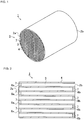
- a honeycomb structure 1 of one embodiment of the present invention has a honeycomb structure body 5 including latticed partition walls 4 defining a plurality of polygonal cells 3 which extends from one end face 2a to the other end face 2b and forms through channels for fluid, and plugging portions 7 formed to close one open end 6a of each of the predetermined cells 3 and the other open end 6b of the residual cells 3 in the plurality of cells 3 constituting the honeycomb structure body 5, respectively, in accordance with a predetermined regular arrangement.
- the plugging portions 7 of the present embodiment are formed to plug one open end 6a (or the other open end 6b) of the cells 3 adjacent to each other, i.e., alternately plug the open ends of the cells (e.g., see Fig. 2 ).
- the honeycomb structure 1 is manufactured by extruding a forming material 10 in which aggregates 8, a bonding material 9 different from a material of the aggregates 8 and a bonding aid 13 are mixed and kneaded, into a desirable honeycomb shape by use of an extruder to form a honeycomb formed body (a forming step), and firing the obtained honeycomb formed body at a predetermined firing temperature (a firing step).
- a DPF is prepared by using the manufactured honeycomb structure 1.
- An exhaust gas of a diesel engine is introduced from one end of this DPF, so that a particulate matter of soot or the like included in the exhaust gas can be trapped by the porous partition walls 4 while the exhaust gas passes the partition walls 4.
- the latticed partition walls 4 constituting the honeycomb structure 1 are mainly constituted of the aggregates 8 and the bonding material 9, and silicon carbide (SiC) is used as the aggregates.
- SiC silicon carbide
- an average size of the aggregates 8 is in a range of 10 to 60 micrometers.
- the bonding material 9 metal silicon (Si) or cordierite is used, and the material having an average particle diameter smaller than that of the aggregates 8 is used.
- silicon carbide as the aggregates 8 is bonded by metal silicon or the like which is the bonding material, and the partition walls 4 are formed.
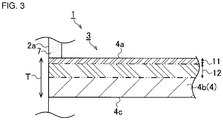
- a surface porosity A concerned with a porosity of a region (a surface region 11) of a partition wall inner portion 4b from the partition wall surface 4a to a depth of 15% and an inner porosity B concerned with a porosity of a region (an inner region 12) of the partition wall inner portion 4b from the partition wall surface 4a to a depth of 15% to 50% of the partition wall thickness T indicate values different from each other, and the value of the inner porosity B is larger than that of the surface porosity A. That is, the porosity of the inner region 12 is higher than that of the surface region 11.
- the surface porosity A mentioned above is in a range of 30% to 40%.
- the inner porosity B is in a range of 35% to 45%.
- a relation between the surface porosity A and the inner porosity B indicates that a difference obtained by subtracting the surface porosity A from the inner porosity B is in excess of 1.5% ("the inner porosity B-the surface porosity A > 1.5%").
- a surface average pore diameter C concerned with an average pore diameter of the surface region 11 of the partition wall 4 and an inner average pore diameter D concerned with an average pore diameter of the inner region 12 indicate different values, and the value of the inner average pore diameter D is larger than that of the surface average pore diameter C.
- the average pore diameter is calculated on the basis of an average distribution of respective pores of each of the surface region 11 and the inner region 12. That is, the average pore diameter of the inner region 12 is larger than that of the surface region 11, and in accordance with the above value of the porosity, the pores having large pore diameters occupy the inner region 12.
- the surface average pore diameter C mentioned above is in a range of 5 to 40 micrometers and further preferably in a range of 10 to 25 micrometers.
- the inner average pore diameter D is in a range of 8 to 50 micrometers and further preferably in a range of 20 to 30 micrometers.
- a relation between the surface average pore diameter C and the inner average pore diameter D indicates that a difference obtained by subtracting the surface average pore diameter C from the inner average pore diameter D is in excess of 0.5 micrometer ("the inner average pore diameter D-the surface average pore diameter C > 0.5 micrometer").
- the forming material 10 is obtained by mixing and kneading the aggregates 8, the bonding material 9 and the bonding aid 13 (a forming material providing step).
- the bonding aid 13 anisotropic particles are used, and the anisotropic particles are, for example, plate-shaped (thin plate-shaped) mica, rod-shaped (fibrous) Al-Si fibers or the like.
- the bonding aid 13 in which an average size in a major axis direction is a size of at least 5 micrometers or more and an aspect ratio of the average size in the major direction to an average size in a minor axis direction is 5 or more. Additionally, in the case of the fibers, diameters are defined as the above minor axis.
- the bonding aid 13 in which a melting point is lower than a melting point of the bonding material 9 (e.g., metal silicon) to be added and a blend ratio is adjusted in a range of 3.0 wt.% to 10.0 wt.%.
- a melting point is lower than a melting point of the bonding material 9 (e.g., metal silicon) to be added and a blend ratio is adjusted in a range of 3.0 wt.% to 10.0 wt.%.
- a trapping efficiency of the particulate matter (the soot) can be improved, increase of a pressure loss can be inhibited, and further, trapping leakage number concentration of the particulate matter can be minimized.
- the anisotropic particles of mica or the like are added as the bonding aid 13 to the bonding material 9 included in the forming material 10 at a predetermined blend ratio, and the firing is performed at a firing temperature higher than the melting point of the bonding material 9, so that the surface porosity A and the surface average pore diameter C of the surface region 11 can indicate values smaller than those of the inner porosity B and the inner average pore diameter D of the inner region 12 of the partition wall 4 of the honeycomb structure 1, respectively.
- the bonding aid 13 is added as the anisotropic particles to the forming material 10, and the porosities and the average pore diameters of the surface region 11 and the inner region 12 of the partition wall 4 are controlled, so that the abovementioned relations can be indicated.
- the particulate matter in the exhaust gas introduced into the DPF formed by using the honeycomb structure 1 is easy to be trapped by the partition wall surface 4a of the partition wall 4 in which the average pore diameter and the porosity are small. That is, the trapping efficiency can be increased, the pores of the partition wall inner portion 4b of the partition wall 4 are hard to be closed with the particulate matter, and hence the increase of the pressure loss can be inhibited. Furthermore, the porosity of the partition wall surface 4a is low, and hence a heat capacity can be increased in the whole partition wall 4, and a soot mass limit can be increased.
- the porosity of the whole partition wall 4 does not decrease, but the porosity of the surface region 11 from the partition wall surface 4a to the depth of 15% is decreased to a limited extent, and in the inner region 12 to the depth of 15% to 50%, the values of the inner porosity B and the inner average pore diameter D are kept at constant levels to the surface region 11.
- the particulate matter of the soot or the like forms a deposited layer (not shown) on the partition wall surface 4a to prevent the pores of the partition wall inner portion 4b from being closed, and hence the increase of the pressure loss due to the exhaust gas introduced into the honeycomb structure 1 can be inhibited.
- the average pore diameter and the porosity of the partition wall inner portion 4b are large, which also contributes to the prevention of the closing of the pores in the partition wall inner portion 4b.
- a depth region (not shown) of 50% to 85% of the partition wall surface 4a (corresponding to 15% to 50% of the partition wall back surface 4c) and a depth region (not shown) of 85% to 100% of the partition wall surface 4a (15% from the partition wall back surface 4c) indicate the same constitutions as in the inner region 12 and the surface region 11, respectively.
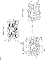
- Fig. 4 illustrates that silicon carbide is used as the aggregates 8, metal silicon is used as the bonding material 9 and thin plate-shaped mica is used as the bonding aid 13.
- the melting point of metal silicon (the bonding material 9) is about 1300°C, and the melting point of mica (the bonding aid 13) is lower than that of metal silicon and between 1200°C and 1300°C. Furthermore, the melting point of silicon carbide (the aggregates 8) is higher than that of metal silicon. It is to be noted that to simplify the description, drawing of a raw material other than the above three components is omitted in the forming material 10.
- the bonding material 9 and the bonding aid 13 are mixed and kneaded at the predetermined blend ratio, to form the forming material 10 in which the above three components are uniformly mixed (the forming material providing step and a bonding aid adding step).
- the average size of the bonding aid 13 is adjusted to be larger than the average size of the bonding material 9. Therefore, at least a part of the bonding material 9 comes in contact with the bonding aid 13 having a large average particle diameter and is bound (see "before firing" in Fig. 4 ).
- the material is extruded by using an extruder, to form the honeycomb formed body (the forming step).
- the obtained honeycomb formed body is sent to the firing step.
- the honeycomb formed body sent to the firing step is thrown into a firing furnace set at a predetermined firing temperature.
- the firing temperature is set at 1300°C or more.
- the bonding aid 13 having the lowest melting point first starts melting. At this time, the molten bonding aid 13 moves from the partition wall inner portion 4b toward the partition wall surface 4a (corresponding to the upside of paper surface in Fig. 4 ) or the partition wall back surface 4c (corresponding to the downside of the paper surface in Fig. 4 ).
- the bonding material 9 melts.
- the bonding aid 13 and the bonding material 9 melt, to bond the aggregates 8 in a state where these bonding aid and bonding material are moved to the partition wall surface 4a (or the partition wall back surface 4c).
- the honeycomb structure 1 discharged from the firing furnace is gradually cooled to the vicinity of room temperature. Consequently, it is considered that the bonding aid 13 and the bonding material 9 moved to the partition wall surface 4a or the like coagulate to form a bonding portion 14 which bonds the aggregates 8 of silicon carbide to one another.
- the surface region 11 of the partition wall surface 4a (or the partition wall back surface 4c) possesses a densified structure as compared with the inner region 12 of the partition wall inner portion 4b, and the partition wall 4 is formed in which a large number of pores having large pore diameters are formed in the partition wall inner portion 4b. Therefore, the porosities and average pore diameters can be controlled to vary in the surface region 11 and the inner region 12.
- the honeycomb structure 1 can be manufactured by using the forming material 10 to which the bonding aid 13 of mica or the like having an aspect ratio of 5 or more is added. Consequently, in the surface region 11 and the inner region 12 of the partition wall 4, the porosities and the average pore diameters can be varied, respectively, and differences in porosity and average pore diameter of the surface region 11 to the inner region 12 can be adjusted to be definite values or more.
- honeycomb structure of the present invention examples of the honeycomb structure of the present invention and the manufacturing method of the honeycomb structure will be described, but the honeycomb structure of the present invention and the manufacturing method of the honeycomb structure are not limited to these examples.
- a bonding material and a bonding aid including anisotropic particles were blended at a predetermined ratio, an organic binder, a surfactant and water were added, uniformly mixed and kneaded, and a forming material obtained in this manner was extruded by utilizing an extruder, to obtain a honeycomb formed body.
- the obtained honeycomb formed body was cut, dried, and then plugged, and firing was performed at a predetermined firing temperature, to obtain a segmented honeycomb structure.
- the honeycomb structure segments were bonded by using a bonding material, and then circumference grinding and circumference coating were performed, thereby preparing honeycomb structures of examples in the present invention and comparative examples.
- silicon carbide was used as aggregates in each of Examples 1 to 17 and Comparative Examples 1 to 13, metal silicon was used as the bonding material in Examples 1 to 8, Examples 15 to 17, Comparative Example 1, Comparative Examples 3 to 7 and Comparative Examples 10 to 13, and cordierite was used as the bonding material in Examples 9 to 14, Comparative Example 2 and Comparative Examples 8 and 9.
- a ratio between the aggregates and the bonding material was 75/25 in each example.
- mica was used in Examples 1 to 14 and Comparative Examples 6 to 13
- Al-Si fibers were used in Examples 15 to 17, and talc was used in Comparative Examples 3 to 5. Additionally, in Comparative Examples 1 and 2, the bonding aid was not added to the forming material.
- a diameter was 144 mm
- a length was 152 mm
- a partition wall thickness of a cell structure was 0.3 mm
- a cell density was 46.5 cells/cm 2 .
- Table 1 mentioned below shows a ratio (75/25) between the above aggregates and the bonding material, particle diameters ( ⁇ m) of the aggregates, particle shapes of the bonding aid, types of bonding aid, long axis side particle diameters ( ⁇ m), and blend ratios (wt.%), and a summary of measurement results of porosities (%) of a surface region and an inner region of each obtained honeycomb structure, average pore diameters ( ⁇ m) of the surface region and the inner region, pressure losses (kPa), and PN leakage numbers (particulates).
- Table 2 mentioned below shows a summary of respective average particle diameters of silicon carbide used as the aggregates, metal silicon used as the bonding material, alumina in cordierite used as the bonding material, and talc in cordierite used as the bonding material, and two types of mica, talc and Al-Si fibers used as the bonding aid in the examples and the comparative examples. Additionally, concerning talc in cordierite, mica, talc as the bonding aid and the Al-Si fibers as the bonding aid, there are also shown average particle diameters in a major axis direction and a minor axis direction and an aspect ratio which is a ratio of an average size of major axis of the particles to that of the minor axis.
- particle dia. (ave. particle dia. in long dia. direction) ⁇ m 6/10/28/ 60/75 6 7 9 25 105 25 20 Ave. particle dia. in short dia. direction ⁇ m - - - 1 or less 3 3 1 or less 3 Aspect ratio (long dia./short dia.) - - - - 25 or more 8.33 35.00 25 or more 6.67
- a scanning electron microscope (SEM) photograph of a partition wall cross section of each of a surface region and an inner region of each partition wall was photographed, and the porosity was calculated by using a commercially available image analysis software. Further specifically, bipolarization processing of an SEM image of the partition wall cross section was performed by using the image analysis software, areas of a partition wall portion (corresponding to the portion other than the pores) and a pore portion in each of the surface region and the inner region were measured, and the porosity in each region was calculated on the basis of a measured value of each obtained area.
- the bipolarization processing based on the photographed SEM image of the wall cross section mentioned below was performed by using the image analysis software, pore diameters of the respective pores in each of the surface region and the inner region of each partition wall were measured, and the average pore diameters were calculated from the obtained pore diameters.
- a DPF was prepared from each of the honeycomb structures of the examples and the comparative examples, a pressure of each of an inlet (an upstream side) and an outlet (a downstream side) of the DPF when passing air at room temperature (25°C) through the filter at a flow rate of 10 Nm 3 /min. was measured, and the pressure loss was obtained by calculating a difference between the pressures.
- the obtained measured value of the pressure loss which was 1.0 kPa or less was judged as "excellent” and the measured value in excess of 1.0 kPa was judged as "failure".
- the DPF formed of each of the honeycomb structures of the examples and the comparative examples was attached to an exhaust system of a vehicle on which a diesel engine having a displacement of 2.0 liters was mounted.
- the PN leakage number was measured from the total number of the particulates of the particulate matter at the outlet (on the downstream side) of the DPF when this vehicle was run in a new European driving cycle (NEDC) mode. Additionally, the measurement of the number of the particulates of the particulate matter was performed in accordance with a technique suggested by a particulate measurement program (abbreviated to "PMP") by the Working Party on Pollution and Energy of World Forum for Harmonization of Vehicle Regulations in United Nations Economic Commission for Europe.
- PMP particulate measurement program
- measured values of the PN leakage number which are smaller than 1.0 ⁇ 10 8 are judged as “excellent”, measured values of 1.0 ⁇ 10 8 or more and 1.0 ⁇ 10 9 or less are judged as “good”, and measured values in excess of 1.0 ⁇ 10 9 are judged as "failure”.
- the DPF prepared on the basis of the honeycomb structure of each of Examples 1 to 17 of the present invention had an excellent or good evaluation in a judgment result of each of the pressure loss and the PN leakage number, whereas the DPF prepared on the basis of the honeycomb structure of each of Comparative Examples 1 to 13 was judged as a failure in at least one of the pressure loss and the PN leakage number.
- the respective items will be described in detail.
- metal silicon was used in the present examples (Examples 1 to 3, etc.) and cordierite was used (Examples 9 to 14, etc.).
- a large difference between the types of bonding material was not especially recognized in one of the evaluation items of the pressure loss and the PN leakage number, and it was confirmed that metal silicon and cordierite were usable as the bonding material.
- the bonding aid (the anisotropic particles) for use, two types of mica which were different in long axis side particle diameters, Al-Si fibers and talc were used.
- the above judgment standards could not be satisfied in the respective items, whereas in mica and the Al-Si fibers, the excellent or good judgment result could be obtained in each item.
- large differences in pressure loss and PN leakage number could not be recognized due to differences in particle diameters of mica (see Examples 1 to 3, Examples 4 to 6, etc.). In consequence, it was confirmed that mica and the Al-Si fibers were effective as the bonding aid.
- the PN leakage number was proportional to the blend ratio of the bonding aid, and in a case where the blend ratio was high (10 wt.%), the smallest value of the PN leakage number was indicated (see Example 3, Example 8, Example 11 and Example 14), whereas in a case where the blend ratio was low (3.0 wt.%), the largest value of the PN leakage number was indicated (see Example 1, Example 6, Example 9 and Example 12). Consequently, in accordance with the blend ratio of the bonding aid, the pressure loss can be decreased and the PN leakage number can be controlled.
- the blend ratio contributed to the respective values of the surface porosity and the inner porosity, and the surface average pore diameter and the inner average pore diameter in the surface region and the inner region. Specifically, it was confirmed that as the blend ratio of the bonding aid to the aggregates increased in Examples 1 to 17, the values of the surface porosity and the surface average pore diameter changed to gradually decrease, whereas the values of the inner porosity and the inner average pore diameter changed to gradually increase.
- each of the difference between the surface porosity and the inner porosity and the difference between the surface average pore diameter and the inner average pore diameter indicated the highest value in the example where the blend ratio of the anisotropic particles was high (10 wt.%), and the difference indicated the lowest value in the example where the blend ratio of the anisotropic particles was low (3.0 wt.%). That is, when a large amount of the anisotropic particles is blended, control can be executed to increase the differences in porosity and average pore diameter between the surface region and the inner region.
- a honeycomb structure of the present invention and a manufacturing method of the honeycomb structure can be utilized in manufacturing of the honeycomb structure which can suitably be utilized as a carrier for a catalyst device or a filter in various fields of cars, chemistry, power, steel and the like.
- the present invention is suitably used as a DPF to trap a particulate matter included in an exhaust gas of a diesel engine.
Landscapes
- Chemical & Material Sciences (AREA)
- Engineering & Computer Science (AREA)
- Ceramic Engineering (AREA)
- Manufacturing & Machinery (AREA)
- Materials Engineering (AREA)
- Structural Engineering (AREA)
- Organic Chemistry (AREA)
- Geometry (AREA)
- Physics & Mathematics (AREA)
- Chemical Kinetics & Catalysis (AREA)
- Combustion & Propulsion (AREA)
- Mechanical Engineering (AREA)
- General Engineering & Computer Science (AREA)
- Inorganic Chemistry (AREA)
- Filtering Materials (AREA)
- Processes For Solid Components From Exhaust (AREA)
- Filtering Of Dispersed Particles In Gases (AREA)
- Porous Artificial Stone Or Porous Ceramic Products (AREA)
Applications Claiming Priority (1)
| Application Number | Priority Date | Filing Date | Title |
|---|---|---|---|
| JP2015071540A JP6227585B2 (ja) | 2015-03-31 | 2015-03-31 | ハニカム構造体、及びハニカム構造体の製造方法 |
Publications (2)
| Publication Number | Publication Date |
|---|---|
| EP3093061A1 EP3093061A1 (en) | 2016-11-16 |
| EP3093061B1 true EP3093061B1 (en) | 2020-01-08 |
Family
ID=55745559
Family Applications (1)
| Application Number | Title | Priority Date | Filing Date |
|---|---|---|---|
| EP16163151.0A Active EP3093061B1 (en) | 2015-03-31 | 2016-03-31 | Honeycomb structure and manufacturing method of honeycomb structure |
Country Status (3)
| Country | Link |
|---|---|
| US (1) | US10195813B2 (enExample) |
| EP (1) | EP3093061B1 (enExample) |
| JP (1) | JP6227585B2 (enExample) |
Families Citing this family (13)
| Publication number | Priority date | Publication date | Assignee | Title |
|---|---|---|---|---|
| JP7100478B2 (ja) * | 2018-03-30 | 2022-07-13 | 日本碍子株式会社 | セラミックス多孔体及びその製造方法、並びに集塵用フィルタ |
| JP7037985B2 (ja) * | 2018-03-30 | 2022-03-17 | 日本碍子株式会社 | ハニカムフィルタ |
| MX2021002538A (es) * | 2018-09-03 | 2021-07-21 | Corning Inc | Cuerpo de panal con material poroso. |
| JP2020158351A (ja) * | 2019-03-27 | 2020-10-01 | 日本碍子株式会社 | ハニカム構造体、および、ハニカム構造体の製造方法 |
| JP6984961B2 (ja) * | 2019-03-29 | 2021-12-22 | 株式会社デンソー | 排ガス浄化フィルタ |
| JP6984962B2 (ja) * | 2019-03-29 | 2021-12-22 | 株式会社デンソー | 排ガス浄化フィルタ |
| JP7118919B2 (ja) * | 2019-03-29 | 2022-08-16 | 株式会社Soken | 排ガス浄化フィルタ |
| JP7002504B2 (ja) * | 2019-07-29 | 2022-02-04 | 株式会社Soken | 排ガス浄化フィルタ |
| JP7002503B2 (ja) * | 2019-07-29 | 2022-02-04 | 株式会社Soken | 排ガス浄化フィルタ |
| JP2023151167A (ja) | 2022-03-31 | 2023-10-16 | 日本碍子株式会社 | 柱状ハニカム構造体 |
| JP7682829B2 (ja) | 2022-03-31 | 2025-05-26 | 日本碍子株式会社 | 柱状ハニカム構造体 |
| JP2023172124A (ja) * | 2022-05-23 | 2023-12-06 | 株式会社リコー | セラミックス構造体及びその製造方法 |
| CN119939787B (zh) * | 2025-04-08 | 2025-06-27 | 中汽研(天津)汽车工程研究院有限公司 | 一种蜂窝铝壁障有限元模型的设计方法 |
Family Cites Families (8)
| Publication number | Priority date | Publication date | Assignee | Title |
|---|---|---|---|---|
| JP2000113513A (ja) | 1998-08-05 | 2000-04-21 | Matsushita Electric Ind Co Ltd | 光学的記録媒体 |
| TW468179B (en) | 1998-08-05 | 2001-12-11 | Matsushita Electric Industrial Co Ltd | Optical recording medium |
| JP2008296141A (ja) | 2007-05-31 | 2008-12-11 | Ngk Insulators Ltd | ハニカムフィルタ |
| JP5208897B2 (ja) | 2008-10-09 | 2013-06-12 | 日本碍子株式会社 | ハニカムフィルタ |
| JP5369035B2 (ja) * | 2010-03-25 | 2013-12-18 | 日本碍子株式会社 | ゼオライトハニカム成形体及びゼオライトハニカム焼成体 |
| US20130330530A1 (en) | 2010-09-16 | 2013-12-12 | Komatsu Seiren Co., Ltd. | Porous Ceramic Sintered Body |
| JP5643692B2 (ja) | 2011-03-25 | 2014-12-17 | 日本碍子株式会社 | ハニカムフィルタ及びその製造方法 |
| JP5864329B2 (ja) * | 2012-03-28 | 2016-02-17 | 日本碍子株式会社 | ハニカム構造体 |
-
2015
- 2015-03-31 JP JP2015071540A patent/JP6227585B2/ja active Active
-
2016
- 2016-03-22 US US15/077,033 patent/US10195813B2/en active Active
- 2016-03-31 EP EP16163151.0A patent/EP3093061B1/en active Active
Non-Patent Citations (1)
| Title |
|---|
| None * |
Also Published As
| Publication number | Publication date |
|---|---|
| JP2016190198A (ja) | 2016-11-10 |
| US20160288449A1 (en) | 2016-10-06 |
| US10195813B2 (en) | 2019-02-05 |
| JP6227585B2 (ja) | 2017-11-08 |
| EP3093061A1 (en) | 2016-11-16 |
Similar Documents
| Publication | Publication Date | Title |
|---|---|---|
| EP3093061B1 (en) | Honeycomb structure and manufacturing method of honeycomb structure | |
| EP1769838B1 (en) | Honeycomb filter | |
| EP1440722B1 (en) | Honeycomb filter | |
| US7138002B2 (en) | Honeycomb structure and process for production thereof | |
| EP2098273B1 (en) | Ceramic honeycomb filter and process for producing the same | |
| EP2119487B1 (en) | Honeycomb structure and method for manufacturing the same | |
| US7169203B2 (en) | Honeycomb structure | |
| EP2106835A1 (en) | Ceramic honeycomb filter and method for manufacturing the same | |
| JP5328174B2 (ja) | 目封止ハニカム構造体 | |
| US9957861B2 (en) | Honeycomb filter | |
| US7073327B2 (en) | Exhaust emission control system, method of calculating pressure loss of filter, and method of manufacturing filter | |
| EP1669123B1 (en) | Ceramic filter | |
| JP6581934B2 (ja) | ハニカムフィルタ | |
| US9470131B2 (en) | Honeycomb structure | |
| EP2108434B1 (en) | Honeycomb structure | |
| US10974186B2 (en) | Ceramic porous body and dust collecting filter | |
| JP2023002191A (ja) | ハニカムフィルタ | |
| JP4773043B2 (ja) | セラミックフィルタ構造体 |
Legal Events
| Date | Code | Title | Description |
|---|---|---|---|
| PUAI | Public reference made under article 153(3) epc to a published international application that has entered the european phase |
Free format text: ORIGINAL CODE: 0009012 |
|
| AK | Designated contracting states |
Kind code of ref document: A1 Designated state(s): AL AT BE BG CH CY CZ DE DK EE ES FI FR GB GR HR HU IE IS IT LI LT LU LV MC MK MT NL NO PL PT RO RS SE SI SK SM TR |
|
| AX | Request for extension of the european patent |
Extension state: BA ME |
|
| STAA | Information on the status of an ep patent application or granted ep patent |
Free format text: STATUS: REQUEST FOR EXAMINATION WAS MADE |
|
| 17P | Request for examination filed |
Effective date: 20170509 |
|
| RBV | Designated contracting states (corrected) |
Designated state(s): AL AT BE BG CH CY CZ DE DK EE ES FI FR GB GR HR HU IE IS IT LI LT LU LV MC MK MT NL NO PL PT RO RS SE SI SK SM TR |
|
| GRAP | Despatch of communication of intention to grant a patent |
Free format text: ORIGINAL CODE: EPIDOSNIGR1 |
|
| STAA | Information on the status of an ep patent application or granted ep patent |
Free format text: STATUS: GRANT OF PATENT IS INTENDED |
|
| INTG | Intention to grant announced |
Effective date: 20190724 |
|
| RIN1 | Information on inventor provided before grant (corrected) |
Inventor name: ICHIKAWA, SHUICHI Inventor name: OUCHI, TAKAHIRO |
|
| GRAS | Grant fee paid |
Free format text: ORIGINAL CODE: EPIDOSNIGR3 |
|
| GRAA | (expected) grant |
Free format text: ORIGINAL CODE: 0009210 |
|
| STAA | Information on the status of an ep patent application or granted ep patent |
Free format text: STATUS: THE PATENT HAS BEEN GRANTED |
|
| AK | Designated contracting states |
Kind code of ref document: B1 Designated state(s): AL AT BE BG CH CY CZ DE DK EE ES FI FR GB GR HR HU IE IS IT LI LT LU LV MC MK MT NL NO PL PT RO RS SE SI SK SM TR |
|
| REG | Reference to a national code |
Ref country code: GB Ref legal event code: FG4D |
|
| REG | Reference to a national code |
Ref country code: CH Ref legal event code: EP |
|
| REG | Reference to a national code |
Ref country code: DE Ref legal event code: R096 Ref document number: 602016027654 Country of ref document: DE |
|
| REG | Reference to a national code |
Ref country code: IE Ref legal event code: FG4D |
|
| REG | Reference to a national code |
Ref country code: AT Ref legal event code: REF Ref document number: 1221987 Country of ref document: AT Kind code of ref document: T Effective date: 20200215 |
|
| REG | Reference to a national code |
Ref country code: NL Ref legal event code: MP Effective date: 20200108 |
|
| REG | Reference to a national code |
Ref country code: LT Ref legal event code: MG4D |
|
| PG25 | Lapsed in a contracting state [announced via postgrant information from national office to epo] |
Ref country code: LT Free format text: LAPSE BECAUSE OF FAILURE TO SUBMIT A TRANSLATION OF THE DESCRIPTION OR TO PAY THE FEE WITHIN THE PRESCRIBED TIME-LIMIT Effective date: 20200108 Ref country code: RS Free format text: LAPSE BECAUSE OF FAILURE TO SUBMIT A TRANSLATION OF THE DESCRIPTION OR TO PAY THE FEE WITHIN THE PRESCRIBED TIME-LIMIT Effective date: 20200108 Ref country code: NO Free format text: LAPSE BECAUSE OF FAILURE TO SUBMIT A TRANSLATION OF THE DESCRIPTION OR TO PAY THE FEE WITHIN THE PRESCRIBED TIME-LIMIT Effective date: 20200408 Ref country code: FI Free format text: LAPSE BECAUSE OF FAILURE TO SUBMIT A TRANSLATION OF THE DESCRIPTION OR TO PAY THE FEE WITHIN THE PRESCRIBED TIME-LIMIT Effective date: 20200108 Ref country code: NL Free format text: LAPSE BECAUSE OF FAILURE TO SUBMIT A TRANSLATION OF THE DESCRIPTION OR TO PAY THE FEE WITHIN THE PRESCRIBED TIME-LIMIT Effective date: 20200108 Ref country code: PT Free format text: LAPSE BECAUSE OF FAILURE TO SUBMIT A TRANSLATION OF THE DESCRIPTION OR TO PAY THE FEE WITHIN THE PRESCRIBED TIME-LIMIT Effective date: 20200531 |
|
| PG25 | Lapsed in a contracting state [announced via postgrant information from national office to epo] |
Ref country code: HR Free format text: LAPSE BECAUSE OF FAILURE TO SUBMIT A TRANSLATION OF THE DESCRIPTION OR TO PAY THE FEE WITHIN THE PRESCRIBED TIME-LIMIT Effective date: 20200108 Ref country code: LV Free format text: LAPSE BECAUSE OF FAILURE TO SUBMIT A TRANSLATION OF THE DESCRIPTION OR TO PAY THE FEE WITHIN THE PRESCRIBED TIME-LIMIT Effective date: 20200108 Ref country code: SE Free format text: LAPSE BECAUSE OF FAILURE TO SUBMIT A TRANSLATION OF THE DESCRIPTION OR TO PAY THE FEE WITHIN THE PRESCRIBED TIME-LIMIT Effective date: 20200108 Ref country code: GR Free format text: LAPSE BECAUSE OF FAILURE TO SUBMIT A TRANSLATION OF THE DESCRIPTION OR TO PAY THE FEE WITHIN THE PRESCRIBED TIME-LIMIT Effective date: 20200409 Ref country code: IS Free format text: LAPSE BECAUSE OF FAILURE TO SUBMIT A TRANSLATION OF THE DESCRIPTION OR TO PAY THE FEE WITHIN THE PRESCRIBED TIME-LIMIT Effective date: 20200508 Ref country code: BG Free format text: LAPSE BECAUSE OF FAILURE TO SUBMIT A TRANSLATION OF THE DESCRIPTION OR TO PAY THE FEE WITHIN THE PRESCRIBED TIME-LIMIT Effective date: 20200408 |
|
| REG | Reference to a national code |
Ref country code: DE Ref legal event code: R097 Ref document number: 602016027654 Country of ref document: DE |
|
| PG25 | Lapsed in a contracting state [announced via postgrant information from national office to epo] |
Ref country code: RO Free format text: LAPSE BECAUSE OF FAILURE TO SUBMIT A TRANSLATION OF THE DESCRIPTION OR TO PAY THE FEE WITHIN THE PRESCRIBED TIME-LIMIT Effective date: 20200108 Ref country code: ES Free format text: LAPSE BECAUSE OF FAILURE TO SUBMIT A TRANSLATION OF THE DESCRIPTION OR TO PAY THE FEE WITHIN THE PRESCRIBED TIME-LIMIT Effective date: 20200108 Ref country code: CZ Free format text: LAPSE BECAUSE OF FAILURE TO SUBMIT A TRANSLATION OF THE DESCRIPTION OR TO PAY THE FEE WITHIN THE PRESCRIBED TIME-LIMIT Effective date: 20200108 Ref country code: DK Free format text: LAPSE BECAUSE OF FAILURE TO SUBMIT A TRANSLATION OF THE DESCRIPTION OR TO PAY THE FEE WITHIN THE PRESCRIBED TIME-LIMIT Effective date: 20200108 Ref country code: SM Free format text: LAPSE BECAUSE OF FAILURE TO SUBMIT A TRANSLATION OF THE DESCRIPTION OR TO PAY THE FEE WITHIN THE PRESCRIBED TIME-LIMIT Effective date: 20200108 Ref country code: EE Free format text: LAPSE BECAUSE OF FAILURE TO SUBMIT A TRANSLATION OF THE DESCRIPTION OR TO PAY THE FEE WITHIN THE PRESCRIBED TIME-LIMIT Effective date: 20200108 Ref country code: MC Free format text: LAPSE BECAUSE OF FAILURE TO SUBMIT A TRANSLATION OF THE DESCRIPTION OR TO PAY THE FEE WITHIN THE PRESCRIBED TIME-LIMIT Effective date: 20200108 Ref country code: SK Free format text: LAPSE BECAUSE OF FAILURE TO SUBMIT A TRANSLATION OF THE DESCRIPTION OR TO PAY THE FEE WITHIN THE PRESCRIBED TIME-LIMIT Effective date: 20200108 |
|
| REG | Reference to a national code |
Ref country code: CH Ref legal event code: PL |
|
| PLBE | No opposition filed within time limit |
Free format text: ORIGINAL CODE: 0009261 |
|
| STAA | Information on the status of an ep patent application or granted ep patent |
Free format text: STATUS: NO OPPOSITION FILED WITHIN TIME LIMIT |
|
| REG | Reference to a national code |
Ref country code: AT Ref legal event code: MK05 Ref document number: 1221987 Country of ref document: AT Kind code of ref document: T Effective date: 20200108 |
|
| 26N | No opposition filed |
Effective date: 20201009 |
|
| REG | Reference to a national code |
Ref country code: BE Ref legal event code: MM Effective date: 20200331 |
|
| PG25 | Lapsed in a contracting state [announced via postgrant information from national office to epo] |
Ref country code: LU Free format text: LAPSE BECAUSE OF NON-PAYMENT OF DUE FEES Effective date: 20200331 |
|
| PG25 | Lapsed in a contracting state [announced via postgrant information from national office to epo] |
Ref country code: AT Free format text: LAPSE BECAUSE OF FAILURE TO SUBMIT A TRANSLATION OF THE DESCRIPTION OR TO PAY THE FEE WITHIN THE PRESCRIBED TIME-LIMIT Effective date: 20200108 Ref country code: IE Free format text: LAPSE BECAUSE OF NON-PAYMENT OF DUE FEES Effective date: 20200331 Ref country code: FR Free format text: LAPSE BECAUSE OF NON-PAYMENT OF DUE FEES Effective date: 20200331 Ref country code: CH Free format text: LAPSE BECAUSE OF NON-PAYMENT OF DUE FEES Effective date: 20200331 Ref country code: LI Free format text: LAPSE BECAUSE OF NON-PAYMENT OF DUE FEES Effective date: 20200331 Ref country code: IT Free format text: LAPSE BECAUSE OF FAILURE TO SUBMIT A TRANSLATION OF THE DESCRIPTION OR TO PAY THE FEE WITHIN THE PRESCRIBED TIME-LIMIT Effective date: 20200108 |
|
| PG25 | Lapsed in a contracting state [announced via postgrant information from national office to epo] |
Ref country code: BE Free format text: LAPSE BECAUSE OF NON-PAYMENT OF DUE FEES Effective date: 20200331 Ref country code: SI Free format text: LAPSE BECAUSE OF FAILURE TO SUBMIT A TRANSLATION OF THE DESCRIPTION OR TO PAY THE FEE WITHIN THE PRESCRIBED TIME-LIMIT Effective date: 20200108 Ref country code: PL Free format text: LAPSE BECAUSE OF FAILURE TO SUBMIT A TRANSLATION OF THE DESCRIPTION OR TO PAY THE FEE WITHIN THE PRESCRIBED TIME-LIMIT Effective date: 20200108 |
|
| GBPC | Gb: european patent ceased through non-payment of renewal fee |
Effective date: 20200408 |
|
| PG25 | Lapsed in a contracting state [announced via postgrant information from national office to epo] |
Ref country code: GB Free format text: LAPSE BECAUSE OF NON-PAYMENT OF DUE FEES Effective date: 20200408 |
|
| PG25 | Lapsed in a contracting state [announced via postgrant information from national office to epo] |
Ref country code: TR Free format text: LAPSE BECAUSE OF FAILURE TO SUBMIT A TRANSLATION OF THE DESCRIPTION OR TO PAY THE FEE WITHIN THE PRESCRIBED TIME-LIMIT Effective date: 20200108 Ref country code: MT Free format text: LAPSE BECAUSE OF FAILURE TO SUBMIT A TRANSLATION OF THE DESCRIPTION OR TO PAY THE FEE WITHIN THE PRESCRIBED TIME-LIMIT Effective date: 20200108 Ref country code: CY Free format text: LAPSE BECAUSE OF FAILURE TO SUBMIT A TRANSLATION OF THE DESCRIPTION OR TO PAY THE FEE WITHIN THE PRESCRIBED TIME-LIMIT Effective date: 20200108 |
|
| PG25 | Lapsed in a contracting state [announced via postgrant information from national office to epo] |
Ref country code: MK Free format text: LAPSE BECAUSE OF FAILURE TO SUBMIT A TRANSLATION OF THE DESCRIPTION OR TO PAY THE FEE WITHIN THE PRESCRIBED TIME-LIMIT Effective date: 20200108 Ref country code: AL Free format text: LAPSE BECAUSE OF FAILURE TO SUBMIT A TRANSLATION OF THE DESCRIPTION OR TO PAY THE FEE WITHIN THE PRESCRIBED TIME-LIMIT Effective date: 20200108 |
|
| PGFP | Annual fee paid to national office [announced via postgrant information from national office to epo] |
Ref country code: DE Payment date: 20260204 Year of fee payment: 11 |