EP3090832A1 - Low-rigidity workpiece machining assistance system - Google Patents
Low-rigidity workpiece machining assistance system Download PDFInfo
- Publication number
- EP3090832A1 EP3090832A1 EP14875324.7A EP14875324A EP3090832A1 EP 3090832 A1 EP3090832 A1 EP 3090832A1 EP 14875324 A EP14875324 A EP 14875324A EP 3090832 A1 EP3090832 A1 EP 3090832A1
- Authority
- EP
- European Patent Office
- Prior art keywords
- workpiece
- machining
- tool
- reaction force
- rotary body
- Prior art date
- Legal status (The legal status is an assumption and is not a legal conclusion. Google has not performed a legal analysis and makes no representation as to the accuracy of the status listed.)
- Granted
Links
- 238000003754 machining Methods 0.000 title claims abstract description 372
- 238000005520 cutting process Methods 0.000 claims description 148
- 238000000227 grinding Methods 0.000 claims description 43
- 230000002093 peripheral effect Effects 0.000 claims description 20
- 230000000717 retained effect Effects 0.000 claims description 20
- 239000004575 stone Substances 0.000 claims description 9
- ZZUFCTLCJUWOSV-UHFFFAOYSA-N furosemide Chemical compound C1=C(Cl)C(S(=O)(=O)N)=CC(C(O)=O)=C1NCC1=CC=CO1 ZZUFCTLCJUWOSV-UHFFFAOYSA-N 0.000 claims description 5
- 238000010586 diagram Methods 0.000 description 34
- 230000009467 reduction Effects 0.000 description 23
- 230000005284 excitation Effects 0.000 description 14
- 238000004519 manufacturing process Methods 0.000 description 11
- 230000000875 corresponding effect Effects 0.000 description 9
- 238000003801 milling Methods 0.000 description 7
- 238000005259 measurement Methods 0.000 description 6
- 230000007246 mechanism Effects 0.000 description 6
- 244000145845 chattering Species 0.000 description 4
- 238000005507 spraying Methods 0.000 description 4
- 229920002803 thermoplastic polyurethane Polymers 0.000 description 4
- 230000002596 correlated effect Effects 0.000 description 3
- 238000001514 detection method Methods 0.000 description 3
- 238000005553 drilling Methods 0.000 description 3
- 230000000694 effects Effects 0.000 description 3
- 229910000743 fusible alloy Inorganic materials 0.000 description 3
- 239000006096 absorbing agent Substances 0.000 description 2
- 239000011248 coating agent Substances 0.000 description 2
- 238000000576 coating method Methods 0.000 description 2
- 230000001276 controlling effect Effects 0.000 description 2
- 239000011347 resin Substances 0.000 description 2
- 229920005989 resin Polymers 0.000 description 2
- 229910045601 alloy Inorganic materials 0.000 description 1
- 239000000956 alloy Substances 0.000 description 1
- 238000004458 analytical method Methods 0.000 description 1
- 230000008859 change Effects 0.000 description 1
- 239000004927 clay Substances 0.000 description 1
- 229920001971 elastomer Polymers 0.000 description 1
- 238000005516 engineering process Methods 0.000 description 1
- 230000006870 function Effects 0.000 description 1
- 238000000034 method Methods 0.000 description 1
- 238000012986 modification Methods 0.000 description 1
- 230000004048 modification Effects 0.000 description 1
- 239000007921 spray Substances 0.000 description 1
Images


Classifications
-
- B—PERFORMING OPERATIONS; TRANSPORTING
- B24—GRINDING; POLISHING
- B24B—MACHINES, DEVICES, OR PROCESSES FOR GRINDING OR POLISHING; DRESSING OR CONDITIONING OF ABRADING SURFACES; FEEDING OF GRINDING, POLISHING, OR LAPPING AGENTS
- B24B41/00—Component parts such as frames, beds, carriages, headstocks
- B24B41/06—Work supports, e.g. adjustable steadies
-
- B—PERFORMING OPERATIONS; TRANSPORTING
- B23—MACHINE TOOLS; METAL-WORKING NOT OTHERWISE PROVIDED FOR
- B23B—TURNING; BORING
- B23B47/00—Constructional features of components specially designed for boring or drilling machines; Accessories therefor
-
- B—PERFORMING OPERATIONS; TRANSPORTING
- B23—MACHINE TOOLS; METAL-WORKING NOT OTHERWISE PROVIDED FOR
- B23C—MILLING
- B23C3/00—Milling particular work; Special milling operations; Machines therefor
-
- B—PERFORMING OPERATIONS; TRANSPORTING
- B23—MACHINE TOOLS; METAL-WORKING NOT OTHERWISE PROVIDED FOR
- B23C—MILLING
- B23C9/00—Details or accessories so far as specially adapted to milling machines or cutter
-
- B—PERFORMING OPERATIONS; TRANSPORTING
- B23—MACHINE TOOLS; METAL-WORKING NOT OTHERWISE PROVIDED FOR
- B23Q—DETAILS, COMPONENTS, OR ACCESSORIES FOR MACHINE TOOLS, e.g. ARRANGEMENTS FOR COPYING OR CONTROLLING; MACHINE TOOLS IN GENERAL CHARACTERISED BY THE CONSTRUCTION OF PARTICULAR DETAILS OR COMPONENTS; COMBINATIONS OR ASSOCIATIONS OF METAL-WORKING MACHINES, NOT DIRECTED TO A PARTICULAR RESULT
- B23Q1/00—Members which are comprised in the general build-up of a form of machine, particularly relatively large fixed members
- B23Q1/72—Auxiliary arrangements; Interconnections between auxiliary tables and movable machine elements
- B23Q1/76—Steadies; Rests
- B23Q1/766—Steadies or rests moving together with the tool support
-
- B—PERFORMING OPERATIONS; TRANSPORTING
- B24—GRINDING; POLISHING
- B24B—MACHINES, DEVICES, OR PROCESSES FOR GRINDING OR POLISHING; DRESSING OR CONDITIONING OF ABRADING SURFACES; FEEDING OF GRINDING, POLISHING, OR LAPPING AGENTS
- B24B47/00—Drives or gearings; Equipment therefor
- B24B47/26—Accessories, e.g. stops
-
- G—PHYSICS
- G05—CONTROLLING; REGULATING
- G05B—CONTROL OR REGULATING SYSTEMS IN GENERAL; FUNCTIONAL ELEMENTS OF SUCH SYSTEMS; MONITORING OR TESTING ARRANGEMENTS FOR SUCH SYSTEMS OR ELEMENTS
- G05B19/00—Programme-control systems
- G05B19/02—Programme-control systems electric
- G05B19/18—Numerical control [NC], i.e. automatically operating machines, in particular machine tools, e.g. in a manufacturing environment, so as to execute positioning, movement or co-ordinated operations by means of programme data in numerical form
- G05B19/402—Numerical control [NC], i.e. automatically operating machines, in particular machine tools, e.g. in a manufacturing environment, so as to execute positioning, movement or co-ordinated operations by means of programme data in numerical form characterised by control arrangements for positioning, e.g. centring a tool relative to a hole in the workpiece, additional detection means to correct position
-
- G—PHYSICS
- G05—CONTROLLING; REGULATING
- G05B—CONTROL OR REGULATING SYSTEMS IN GENERAL; FUNCTIONAL ELEMENTS OF SUCH SYSTEMS; MONITORING OR TESTING ARRANGEMENTS FOR SUCH SYSTEMS OR ELEMENTS
- G05B19/00—Programme-control systems
- G05B19/02—Programme-control systems electric
- G05B19/18—Numerical control [NC], i.e. automatically operating machines, in particular machine tools, e.g. in a manufacturing environment, so as to execute positioning, movement or co-ordinated operations by means of programme data in numerical form
- G05B19/404—Numerical control [NC], i.e. automatically operating machines, in particular machine tools, e.g. in a manufacturing environment, so as to execute positioning, movement or co-ordinated operations by means of programme data in numerical form characterised by control arrangements for compensation, e.g. for backlash, overshoot, tool offset, tool wear, temperature, machine construction errors, load, inertia
-
- G—PHYSICS
- G05—CONTROLLING; REGULATING
- G05B—CONTROL OR REGULATING SYSTEMS IN GENERAL; FUNCTIONAL ELEMENTS OF SUCH SYSTEMS; MONITORING OR TESTING ARRANGEMENTS FOR SUCH SYSTEMS OR ELEMENTS
- G05B2219/00—Program-control systems
- G05B2219/30—Nc systems
- G05B2219/40—Robotics, robotics mapping to robotics vision
- G05B2219/40154—Moving of objects
-
- G—PHYSICS
- G05—CONTROLLING; REGULATING
- G05B—CONTROL OR REGULATING SYSTEMS IN GENERAL; FUNCTIONAL ELEMENTS OF SUCH SYSTEMS; MONITORING OR TESTING ARRANGEMENTS FOR SUCH SYSTEMS OR ELEMENTS
- G05B2219/00—Program-control systems
- G05B2219/30—Nc systems
- G05B2219/49—Nc machine tool, till multiple
- G05B2219/49048—Control of damping of vibration of machine base
-
- G—PHYSICS
- G05—CONTROLLING; REGULATING
- G05B—CONTROL OR REGULATING SYSTEMS IN GENERAL; FUNCTIONAL ELEMENTS OF SUCH SYSTEMS; MONITORING OR TESTING ARRANGEMENTS FOR SUCH SYSTEMS OR ELEMENTS
- G05B2219/00—Program-control systems
- G05B2219/30—Nc systems
- G05B2219/49—Nc machine tool, till multiple
- G05B2219/49127—Variable clamping force as function of movement, force on workpiece
-
- G—PHYSICS
- G05—CONTROLLING; REGULATING
- G05B—CONTROL OR REGULATING SYSTEMS IN GENERAL; FUNCTIONAL ELEMENTS OF SUCH SYSTEMS; MONITORING OR TESTING ARRANGEMENTS FOR SUCH SYSTEMS OR ELEMENTS
- G05B2219/00—Program-control systems
- G05B2219/30—Nc systems
- G05B2219/50—Machine tool, machine tool null till machine tool work handling
- G05B2219/50391—Robot
Definitions
- the present invention relates to a machining assistance system, and particularly to a machining assistance system for assisting in machining a low-rigidity workpiece, such as a thin plate or a thin-wall cylinder.
- a machine tool is used in the machining, in which a workpiece, i.e., a machining target object, and a working tool are moved (i.e., rotated or linearly moved) relative to each other, and the workpiece is machined into an intended shape.
- a workpiece i.e., a machining target object
- a working tool are moved (i.e., rotated or linearly moved) relative to each other, and the workpiece is machined into an intended shape.
- NC machine tools the machining by which is automated by numerical control, are mainly used.
- An object of the present invention is, in machining a low-rigidity workpiece, to prevent a reduction in machining precision due to deformation of the workpiece while suppressing a reduction in production efficiency.
- a machining assistance system is a system for assisting a machining apparatus, the machining apparatus including: a workpiece retaining tool that retains a workpiece; a machining unit that machines the workpiece retained by the workpiece retaining tool by driving a working tool; and a machining control device that performs control of moving the machining unit relative to the workpiece retaining tool to position the working tool at a machining position.
- the machining assistance system includes: a workpiece supporting force generating unit that generates workpiece supporting force against machining reaction force that is exerted on a machining portion of the workpiece by the working tool; a supporting device that moves the supporting force generating unit while supporting the supporting force generating unit; and a workpiece supporting force control device that controls operation of the workpiece supporting force generating unit and operation of the supporting device based on machining reaction force related data related to the machining reaction force and machining position related data related to the machining position of the working tool, such that the workpiece supporting force generating unit exerts the workpiece supporting force on the workpiece against the machining reaction force.
- the workpiece supporting force generating unit generates workpiece supporting force against machining reaction force that is exerted on the machining portion of the workpiece by the working tool, and the supporting device moves the supporting force generating unit while supporting the supporting force generating unit.
- the workpiece supporting force control device controls the operation of the workpiece supporting force generating unit and the operation of the supporting device based on the machining reaction force related data and the machining position related data, such that the workpiece supporting force generating unit exerts the workpiece supporting force on the workpiece against the machining reaction force.
- the machining reaction force herein means force that is exerted from the working tool to the workpiece at the time of machining.
- cutting resistance is exerted from the workpiece to the working tool.
- reaction force against the cutting resistance is the reaction force (cutting reaction force).
- the machining unit may be configured to perform machining of the workpiece retained by the workpiece retaining tool by causing a columnar or discoid rotating tool with a cutting edge or grinding stone formed on its peripheral surface or distal end surface to rotate about a central axis of the rotating tool.
- the workpiece supporting force generating unit may include a columnar rotary body and a rotation driver that causes the rotary body to rotate about a central axis of the rotary body.
- the workpiece supporting force control device may be configured to, based on the machining reaction force related data and the machining position related data and by using the supporting device, perform: control of an orientation and a position of the workpiece supporting force generating unit, such that the central axis of the rotary body is parallel to the central axis of the rotating tool, and the rotary body exerts pushing force on the workpiece against cutting reaction force that is exerted on the workpiece by the rotating tool; and control of operation of the rotation driver to cause the rotary body to rotate, such that a rotational torque is exerted on the workpiece against a torque that is generated by the cutting reaction force.
- the machining herein includes cutting and grinding.
- the workpiece supporting force control device performs: control of the orientation and the position of the workpiece supporting force generating unit, such that the central axis of the rotary body is parallel to the central axis of the rotating tool, and the rotary body exerts pushing force on the workpiece against cutting reaction force that is exerted on the workpiece by the rotating tool; and control of the operation of the rotation driver to cause the rotary body to rotate, such that a rotational torque is exerted on the workpiece against a torque that is generated by the cutting reaction force.
- the machining apparatus is an apparatus for performing machining of the workpiece by the rotating tool, even if the workpiece is a low-rigidity workpiece, a reduction in machining precision due to deformation of the workpiece can be prevented while suppressing a reduction in production efficiency.
- the machining unit may be configured to perform cutting of a side surface of the workpiece retained by the workpiece retaining tool by causing a columnar rotating cutting tool with a cutting edge formed on its peripheral surface to rotate about a central axis of the rotating cutting tool
- the workpiece supporting force control device may be configured to, based on the machining reaction force related data and the machining position related data and by using the supporting device, perform: control of the orientation and the position of the workpiece supporting force generating unit, such that the central axis of the rotary body is parallel to the central axis of the rotating cutting tool, a peripheral surface of the rotary body faces the peripheral surface of the rotating cutting tool with the workpiece positioned in between, and the peripheral surface of the rotary body exerts pushing force on the workpiece against cutting reaction force that is exerted on the workpiece by the rotating cutting tool; and control of operation of the rotation driver to cause the rotary body to rotate in the same direction as a rotation direction of the rotating cutting tool, such that a rotational torque is exerted on the workpiece against
- the workpiece supporting force control device performs: control of the orientation and the position of the workpiece supporting force generating unit, such that the central axis of the rotary body is parallel to the central axis of the rotating cutting tool, the peripheral surface of the rotary body faces the peripheral surface of the rotating cutting tool with the workpiece positioned in between, and the peripheral surface of the rotary body exerts pushing force on the workpiece against cutting reaction force that is exerted on the workpiece by the rotating cutting tool; and control of the operation of the rotation driver to cause the rotary body to rotate in the same direction as the rotation direction of the rotating cutting tool, such that a rotational torque is exerted on the workpiece against a torque that is generated by the cutting reaction force.
- the machining apparatus is an apparatus for performing cutting of a side surface of the workpiece by the rotating cutting tool, even if the workpiece is a low-rigidity workpiece, a reduction in machining precision due to deformation of the workpiece can be prevented while suppressing a reduction in production efficiency.
- the machining unit may be configured to perform cutting of a surface of the workpiece retained by the workpiece retaining tool by causing a columnar rotating cutting tool with a cutting edge formed on its distal end surface to rotate about a central axis of the rotating cutting tool
- the workpiece supporting force control device may be configured to, based on the machining reaction force related data and the machining position related data and by using the supporting device, perform: control of the orientation and the position of the workpiece supporting force generating unit, such that the central axis of the rotary body is parallel to the central axis of the rotating cutting tool, a distal end surface of the rotary body faces the distal end surface of the rotating cutting tool with the workpiece positioned in between, and the distal end surface of the rotary body exerts pushing force on the workpiece against cutting reaction force that is exerted on the workpiece by the rotating cutting tool; and control of operation of the rotation driver to cause the rotary body to rotate in a direction reverse to a rotation direction of the rotating cutting tool, such that a rotational torque is
- the workpiece supporting force control device performs: control of the orientation and the position of the workpiece supporting force generating unit, such that the central axis of the rotary body is parallel to the central axis of the rotating cutting tool, the distal end surface of the rotary body faces the distal end surface of the rotating cutting tool with the workpiece positioned in between, and the distal end surface of the rotary body exerts pushing force on the workpiece against cutting reaction force that is exerted on the workpiece by the rotating cutting tool; and control of the operation of the rotation driver to cause the rotary body to rotate in the direction reverse to the rotation direction of the rotating cutting tool, such that a rotational torque is exerted on the workpiece against a torque that is generated by the cutting reaction force.
- the machining apparatus is an apparatus for performing milling or hole machining on a surface of the workpiece by the rotating cutting tool, even if the workpiece is a low-rigidity workpiece, a reduction in machining precision due to deformation of the workpiece can be prevented while suppressing a reduction in production efficiency.
- the machining unit may be configured to perform grinding of a side surface of the workpiece retained by the workpiece retaining tool by causing a discoid rotating grinding tool with grinding stone formed on its peripheral surface to rotate about a central axis of the rotating grinding tool
- the workpiece supporting force control device may be configured to, based on the machining reaction force related data and the machining position related data and by using the supporting device, perform: control of the orientation and the position of the workpiece supporting force generating unit, such that the central axis of the rotary body is parallel to the central axis of the rotating grinding tool, and the rotary body exerts pushing force on the workpiece against grinding reaction force that is exerted on the workpiece by the rotating grinding tool; and control of operation of the rotation driver to cause the rotary body to rotate, such that a rotational torque is exerted on the workpiece against a torque that is generated by the grinding reaction force.
- the workpiece supporting force control device performs: control the orientation and the position of the workpiece supporting force generating unit, such that the central axis of the rotary body is parallel to the central axis of the rotating grinding tool, and the rotary body exerts pushing force on the workpiece against grinding reaction force that is exerted on the workpiece by the rotating grinding tool; and control of the operation of the rotation driver to cause the rotary body to rotate, such that a rotational torque is exerted on the workpiece against a torque that is generated by the grinding reaction force.
- the machining apparatus is an apparatus for performing grinding of a side surface of the workpiece by the rotating grinding stone, even if the workpiece is a low-rigidity workpiece, a reduction in machining precision due to deformation of the workpiece can be prevented while suppressing a reduction in production efficiency.
- the machining assistance system may further include a dynamometer that detects motive power exerted on the workpiece, and the machining reaction force related data may be the motive power detected by the dynamometer.
- the motive power exerted on the workpiece during the machining is directly detected in real time by the dynamometer.
- This makes it possible to perform accurate feedback control of the workpiece supporting force by using the motive power detected by the dynamometer.
- the motive power exerted on the workpiece is detected by the dynamometer, and feedback control of the workpiece supporting force is performed, such that the value of the detected motive power is kept to zero.
- the machining unit may include the working tool and a motor that drives the working tool.
- the machining assistance system may further include a current sensor that detects an electric current flowing through the motor.
- the machining reaction force related data may be a current value of the electric current flowing through the motor, the electric current being detected by the current sensor.
- the current value of the motor driving the working tool is a value corresponding to the machining reaction force. Accordingly, the machining reaction force exerted on the workpiece during the machining is indirectly detected in real time by the current sensor. This makes it possible to perform feedforward control of the workpiece supporting force by using the motor current value detected by the current sensor.
- the machining assistance system may further include a vibration meter that is provided on the workpiece retaining tool and that measures vibration of the workpiece retained by the workpiece retaining tool, and the machining reaction force related data may be the vibration measured by the vibration meter.
- the vibration of the workpiece corresponds to the machining reaction force exerted on the workpiece. Accordingly, the machining reaction force exerted on the workpiece during the machining is indirectly measured in real time by the vibration meter. This makes it possible to perform feedback control of the workpiece supporting force by using the vibration measured by the vibration meter. Consequently, vibration of the workpiece can be suppressed. (It should be noted that since the number of chattering vibrations differs at each machining position, the strength of the pushing force exerted by the supporting force generating unit may be changed for each machining position.)
- the machining assistance system may further include a memory for storing the machining reaction force related data.
- the workpiece supporting force control device may control the operation of the workpiece supporting force generating unit and the operation of the supporting device based on the machining position related data and the machining reaction force related data stored in the memory.
- the machining reaction force for each machining position is experimentally or theoretically estimated in advance, and the workpiece supporting force can be controlled based thereon.
- This makes it possible to eliminate the devices for detecting the machining reaction force and simplify the machining assistance system.
- cutting resistance may be measured by a dynamometer in advance, and cutting reaction force estimated based on experimental data may be stored.
- the supporting device may be an articulated arm robot that retains the workpiece supporting force generating unit by a hand, and the workpiece supporting force control device may be configured to control operation of the articulated arm robot and the operation of the workpiece supporting force generating unit.
- the machining portion of a surface of the workpiece may be coated with a film that increases rigidity of the workpiece and that is machinable together with the workpiece.
- the following pre-machining treatment may be performed: coating the machining portion of the surface of the workpiece with a film made of, for example, foamed resin or low-melting alloy.
- the present invention produces an advantageous effect of being able to prevent, in machining a low-rigidity workpiece, a reduction in machining precision due to deformation of the workpiece while suppressing a reduction in production efficiency
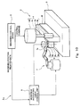
- Fig. 1 is a block diagram showing the configuration of a machining assistance system according to Embodiment 1 of the present invention.
- a machining assistance system 1 is a system for assisting a machining apparatus 2, which performs machining of a workpiece W automatically.
- the machining apparatus 2 includes: a workpiece retaining tool 3, which retains the workpiece W; a machining unit 4; and a machining control device 5.
- the machining apparatus 2 is, for example, a machining center capable of performing different types of machining in accordance with the purpose of the machining, such as side surface cutting, front surface cutting, hole machining, and grinding.
- the workpiece retaining tool 3 may be any tool, so long as it is capable of retaining the workpiece W.
- the workpiece retaining tool 3 includes, for example, a base and a mechanism that fixes the workpiece W on the base.
- the workpiece W is not limited to a particular type of workpiece, the less the rigidity of the workpiece W is, the more the functional advantages of the present invention are exerted.
- the workpiece W i.e., a machining target object in the present embodiment, is, for example, in the shape of a thin plate with low rigidity.
- the workpiece W may have a different shape, so long as the rigidity of the workpiece W is low.
- the workpiece W may be a thin-wall cylinder.
- the machining unit 4 machines the workpiece W retained by the workpiece retaining tool 3 by driving a working tool 4a.
- the machining unit 4 is configured to cut a side surface of the workpiece W retained by the workpiece retaining tool 3 by causing the columnar rotating cutting tool 4a with cutting edges formed on its peripheral surface to rotate about a central axis 4c.
- a driver 4d of the machining unit 4 includes, for example, a servomotor therein, and drives the rotating cutting tool 4a to rotate about the central axis 4c of a main shaft 4b (i.e., the central axis of the rotating cutting tool 4a).
- the machining control device 5 performs control of moving the machining unit 4 relative to the workpiece retaining tool 3 to position the working tool 4a at a machining position.
- the machining control device 5 includes: a moving mechanism (not shown) that moves the machining unit 4 relative to the workpiece retaining tool 3; and a controller (not shown) that controls the movement of the machining unit 4 relative to the workpiece retaining tool 3.
- the workpiece retaining tool 3 is fixed, and the machining unit 4 is moved by the moving mechanism.
- the controller performs computer numerical control (CNC) to control the position of the machining unit 4 by means of the moving mechanism and to control the operation of the machining unit 4, thereby controlling a cutting operation that the rotating cutting tool 4a performs on the workpiece W.
- CNC computer numerical control
- the definition of machining position related data herein includes both data indicating the machining position and data correlated with the machining position.
- the machining assistance system 1 includes a workpiece supporting force generating unit 6, a supporting device 7, a dynamometer 9, and a workpiece supporting force control device 8.
- the workpiece supporting force generating unit 6 generates workpiece supporting force against machining reaction force that is exerted on a machining portion of the workpiece W by the working tool 4a.
- the workpiece supporting force generating unit 6 includes a columnar rotary body 6a, a base 6b, and a rotation driver 6d.
- the columnar rotary body 6a is formed as an elastic body, for example. The elasticity of the elastic body is suitably selected by taking account of pushing force described below, the chattering frequency of the workpiece W, and so forth.
- the rotary body 6a is a rubber roller.
- the rotary body 6a includes a rotary shaft (not shown) whose central axis is an axis 6c.
- the rotary shaft is rotatably retained by the base 6b via bearings (not shown).
- the rotation driver 6d is mounted to the base 6b, and causes the rotary body 6a to rotate about the axis 6c in accordance with a rotational torque command from the workpiece supporting force control device 8.
- the rotation driver 6d is configured, for example, as a motor, and the main shaft of the motor is coaxially connected to the rotary shaft of the rotary body 6a.
- the motor is a servomotor, for example.
- the machining reaction force herein means force that is exerted from the working tool to the workpiece at the time of machining.
- cutting resistance is exerted from the workpiece W to the working tool 4a.
- reaction force against the cutting resistance is the reaction force (cutting reaction force).
- the supporting device 7 is not limited to a particular device, so long as the supporting device 7 moves the supporting force generating unit 6 while supporting the supporting force generating unit 6.
- the supporting device 7 is, for example, an articulated arm robot provided with a plurality of joint axes that are necessary for its operation.
- the articulated arm robot 7 retains the base 6b of the workpiece supporting force generating unit 6 by a hand 7a provided at the distal end of the arm.
- the dynamometer 9 detects motive power exerted on the workpiece W.
- the dynamometer 9 is provided in such a manner as to support the base of the workpiece retaining tool 3 of the machining apparatus 2, and detects motive power (a load) exerted on the workpiece W.
- the dynamometer 9 outputs the detected motive power to the workpiece supporting force control device 8 as machining reaction force related data.
- the definition of machining reaction force related data includes both data of machining reaction force and data correlated with the machining reaction force.
- the motive power detected by the dynamometer 9 is the resultant force of machining reaction force exerted on the workpiece W and workpiece supporting force exerted on the workpiece W by the supporting force generating unit 6, the motive power detected by the dynamometer 9 is data correlated with the machining reaction force.
- the workpiece supporting force control device 8 controls the operation of the workpiece supporting force generating unit 6 and the operation of the supporting device 7, such that the workpiece supporting force generating unit 6 exerts workpiece supporting force on the workpiece W against the machining reaction force.
- the workpiece supporting force control device 8 is configured to control the operation of the articulated arm robot 7 and control the operation of the workpiece supporting force generating unit 6.
- the workpiece supporting force control device 8 is configured to: control the orientation and the position of the workpiece supporting force generating unit 6, such that the rotary body 6a exerts pushing force on the workpiece W against cutting reaction force that is exerted on the workpiece W by the rotating cutting tool 4a; and control the operation of the rotation driver 6d, such that the rotary body 6a rotates and exerts a rotational torque on the workpiece W against a torque that is generated by the cutting reaction force.
- Fig. 2 is a block diagram showing the configuration of the workpiece supporting force control device (which may be hereinafter simply referred to as a supporting force control device) 8.
- the workpiece supporting force control device 8 includes a memory 8a, a motive power target value setter 8b, an adder-subtracter 8c, a compensator 8d, a component force calculator 8e, and a robot controller 8f.
- the workpiece supporting force control device 8 is configured, for example, as an arithmetic operation device such as a microcontroller or the like.
- the memory 8 a is configured, for example, as an internal memory of the microcontroller or the like.
- the aforementioned blocks 8b to 8e are functional blocks that are realized when the microcontroller executes a predetermined installed program.
- the memory 8a stores various data, such as a target value of the motive power (hereinafter, referred to as a motive power target value).
- the motive power target value setter 8b retrieves the motive power target value stored in the memory 8a, and outputs the retrieved motive power target value to the adder-subtracter 8c.
- the motive power target value is set to zero, and when the motive power detected by the dynamometer 9 (hereinafter, referred to as a motive power detection value) is zero, it means that proper supporting force is exerted on the workpiece W.
- the adder-subtracter 8c outputs a deviation of the motive power target value from the motive power detection value (hereinafter, referred to as a motive power deviation), which is a value obtained by subtracting the motive power detection value from the motive power target value, to the compensator 8d.
- a motive power deviation a deviation of the motive power target value from the motive power detection value
- the compensator 8d performs, for example, PID compensation on the motive power deviation, and outputs the compensated motive power deviation to the component force calculator 8e.
- the component force calculator 8e calculates pushing force that the rotary body 6a exerts against cutting reaction force that is exerted on the workpiece W by the rotating cutting tool 4a, and calculates a rotational torque that the rotary body 6a exerts, by rotating, against a torque that is generated by the cutting reaction force.
- the cutting reaction force can be divided into: tangential-direction component force, which is exerted in the tangential direction of the rotating cutting tool 4a; perpendicular-direction component force, which is exerted perpendicularly to the tangential-direction component force; and axial-direction component force, which is exerted in the direction of the rotational axis 4c.
- the ratio among the tangential-direction component force, the perpendicular-direction component force, and the axial-direction component force can be estimated based on the manner of performing the cutting work, or can be detected by the dynamometer 9. Thus, the ratio is known. Based on the known ratio, the component force calculator 8e calculates the pushing force and the rotational torque. In addition, the component force calculator 8e outputs a command value of the calculated pushing force to the robot controller 8f, and outputs a command value of the calculated rotational torque to the rotation driver 6d.
- the robot controller 8f controls the operation of the articulated arm robot, which serves as the supporting device 7.
- the robot controller 8f based on the machining position related data obtained from the machining control device 5, the robot controller 8f outputs an operation control signal to the articulated arm robot 7, such that the supporting force generating unit 6 is positioned at a position corresponding to a machining position where the rotating cutting tool 4a performs machining.
- the robot controller 8f converts the machining position related data represented in a coordinate system of the machining apparatus 2 into data represented in a coordinate system of the articulated arm robot 7, and controls the operation of the articulated arm robot 7 by using the converted data, such that the axis 6c of the rotary body 6a is parallel to the rotational axis of the rotating cutting tool 4a, and such that the position of the rotary body 6a in the height direction and the position of the rotary body 6a in the feed direction of the rotating cutting tool 4a correspond to the machining position where the rotating cutting tool 4a performs machining. Accordingly, the rotary body 6a moves in a manner to follow the movement of the machining position where the rotating cutting tool 4a performs machining.
- the robot controller 8f outputs an operation control signal to the articulated arm robot 7 to exert pushing force on the workpiece W via the rotary body 6a of the supporting force generating unit 6. Specifically, in accordance with the pushing force command value, the robot controller 8f controls the operation of the articulated arm robot 7 to change the position of the rotary body 6a and the pushing force in the thickness direction of the workpiece W. In this manner, the pushing force based on the pushing force command value is exerted on the workpiece W by the rotary body 6a.
- the rotation driver 6d controls the rotary body 6a of the supporting force generating unit 6 to exert a rotational torque on the workpiece W based on the rotational torque command value obtained from the component force calculator 8e. Specifically, the rotation driver 6d causes the rotary body 6a to rotate in the same direction as the rotation direction of the rotating cutting tool 4a with a rotational torque corresponding to the rotational torque command value. In this manner, the rotational torque corresponding to the rotational torque command value is exerted on the workpiece W by the rotary body 6a.
- Figs. 3A and 3B are schematic diagrams for describing workpiece supporting force (which may be hereinafter simply referred to as supporting force) exerted by the machining assistance system 1 when side surface cutting is performed.
- a plan view of Fig. 3A and a perspective view of Fig. 3B only show the rotating cutting tool 4a of the machining unit 4, the workpiece W, and the rotary body 6a of the supporting force generating unit 6 for the sake of convenience of the description.
- Figs. 3A and 3B are schematic diagrams for describing
- the workpiece supporting force control device 8 uses the supporting device (articulated arm robot) 7 to control the orientation and the position of the workpiece supporting force generating unit 6, such that: the axis 6c of the rotary body 6a is parallel to the central axis 4c of the rotating cutting tool 4a; the peripheral surface of the rotary body 6a faces the peripheral surface of the rotating cutting tool 4a with the workpiece W positioned in between; and the peripheral surface of the rotary body 6a exerts pushing force F' 2 on the workpiece W against perpendicular-direction component force F 2 of the cutting reaction force that is exerted on the workpiece W by the rotating cutting tool 4a.
- the workpiece supporting force control device 8 controls the operation of the rotation driver 6d to cause the rotary body 6a to rotate in a direction
- the machining apparatus 2 is an apparatus for performing cutting of a side surface of the workpiece by means of the rotating cutting tool 4a as in Embodiment 1
- the workpiece supporting force is controlled to substantially match the machining reaction force, and thereby deformation of the workpiece W due to the machining reaction force can be prevented even if the workpiece W is a low-rigidity workpiece. Consequently, a reduction in machining precision due deformation of the workpiece W can be prevented. Since it is not necessary to, for example, reduce the machining conditions, a reduction in production efficiency can be suppressed.
- Embodiment 2 of the present invention is described.
- the same components as those described in Embodiment 1 are denoted by the same reference signs as those used in Embodiment 1, and the description of such common components is omitted.
- a description is given focusing on differences from Embodiment 1.
- Fig. 4 is a block diagram showing the configuration of a machining assistance system according to Embodiment 2.
- Embodiment 2 is different from Embodiment 1 in that a machining assistance system 1a according to Embodiment 2 further includes a current sensor 10, which detects an electric current flowing through the motor of the driver 4d of the machining unit 4, and the machining reaction force related data is a current value of the electric current flowing through the motor, which is detected by the current sensor 10.
- the current value of the motor driving the rotating cutting tool 4a is a value corresponding to the machining reaction force.
- Fig. 5 is a block diagram showing the configuration of the workpiece supporting force control device 8 in the machining assistance system 1a of Fig. 4 .
- the workpiece supporting force control device 8 includes a machining reaction force calculator 8g.
- the memory 8a stores, as machining position related data, for example, data of the position of the rotary body 6a, which is taught in advance.
- the robot controller 8f retrieves the machining position related data taught in advance from the memory 8a, and based on the retrieved data, controls the operation of the articulated arm robot 7, such that the rotary body 6a moves in a manner to follow the movement of the machining position where the rotating cutting tool 4a performs machining.
- the machining reaction force calculator 8g receives a current value from the current sensor 10 as machining reaction force related data, refers to the table, retrieves the machining reaction force that corresponds to the received current value from the memory 8a, and outputs the retrieved machining reaction force to the component force calculator 8e.
- feedforward control is performed, such that the pushing force and the rotational torque exerted by the rotary body 6a correspond to the current value of the motor of the machining unit 4.
- workpiece supporting force that substantially matches the machining reaction force exerted on the workpiece W is exerted on the machining portion of the workpiece W, and thereby deformation of the workpiece due to the machining reaction force is prevented.
- the machining reaction force exerted on the workpiece W during the machining is indirectly detected in real time by the current sensor 10. This makes it possible to perform feedforward control of the workpiece supporting force by using the motor current value detected by the current sensor 10.
- Embodiment 3 of the present invention is described.
- the same components as those described in Embodiment 1 are denoted by the same reference signs as those used in Embodiment 1, and the description of such common components is omitted.
- a description is given focusing on differences from Embodiment 1.
- Fig. 6 is a block diagram showing the configuration of a machining assistance system according to Embodiment 3 of the present invention.
- Embodiment 3 is different from Embodiment 1 in that a machining assistance system 1b according to Embodiment 3 includes a vibration meter 11 in place of the dynamometer 9 of Embodiment 1, the vibration meter 11 being provided on the base of the workpiece retaining tool 3 and measuring vibration of the workpiece W during machining, and the machining reaction force related data is the vibration measured by the vibration meter 11.
- the vibration of the workpiece W corresponds to the machining reaction force exerted on the workpiece W.
- Fig. 7 is a block diagram showing the configuration of the workpiece supporting force control device in the machining assistance system 1b.
- the workpiece supporting force control device 8 includes a vibration target value setter 8h.
- the vibration target value setter 8h retrieves a vibration target value stored in the memory 8a, and outputs the retrieved vibration target value to the adder-subtracter 8c.
- the vibration target value is set to zero, and when the vibration measured by the vibration meter 11 (hereinafter, referred to as a vibration measurement value) is zero, it means that proper supporting force is exerted on the workpiece W.
- the adder-subtracter 8c outputs a deviation of the vibration target value from the vibration measurement value (hereinafter, referred to as a vibration deviation), which is a value obtained by subtracting the vibration measurement value from the vibration target value, to the compensator 8d.
- a vibration deviation a deviation of the vibration target value from the vibration measurement value
- the compensator 8d performs, for example, PID compensation on the vibration deviation, and outputs the compensated vibration deviation to the component force calculator 8e.
- the component force calculator 8e Based on the compensated vibration deviation, the component force calculator 8e outputs a pushing force command value and a rotational torque command value. Since the operations thereafter are the same as those described in Embodiment 1, the description thereof is omitted.
- the machining reaction force exerted on the workpiece W during the machining is indirectly measured in real time by the vibration meter 11. This makes it possible to perform feedback control of the workpiece supporting force by using the vibration measured by the vibration meter 11. Consequently, vibration of the workpiece W can be suppressed.
- Fig. 8 is a block diagram showing the configuration of a machining assistance system according to Variation 1 of Embodiment 3 of the present invention.
- the base 6b of the rotation driver 6d is supported by an excitation device 12 for actively suppressing vibration.
- a known excitation device can be used as the excitation device 12. Since the structure of such an excitation device is well known, the description thereof is given below briefly.
- the excitation device 12 includes, for example, a movable body (not shown) elastically supported by a base (not shown) and an exciter (not shown) that causes the movable body to vibrate.
- the base 6b of the rotation driver 6d is retained by the movable body, and the base of the excitation device 12 is retained by the hand 7a of the articulated arm robot 7.
- the excitation device 12 is configured to apply predetermined vibration to the rotary body 6a based on a vibration command from the workpiece supporting force control unit 8.
- the excitation device 12 is, for example, an electromagnetic excitation device of a permanent magnet type.
- Fig. 9 is a block diagram showing the configuration of the workpiece supporting force control device in the machining assistance system of Fig. 8 .
- the workpiece supporting force control device 8 further includes a vibration command value calculator 8j.
- the vibration command value calculator 8j calculates a vibration command value based on the vibration measurement value received from the vibration meter 11, and outputs the vibration command value to the excitation device 12.
- the vibration command value calculator 8j has, for example, a Fourier analysis function, and calculates the frequency and amplitude of major frequency components from the received vibration measurement value, and generates and outputs such a vibration command value as to cancel the major frequency components to the excitation device 12.
- the excitation device 12 actively generates vibration that cancels the vibration of the vibration measurement value.
- the generated vibration is superimposed on the pushing force via the rotary body 6a, and is transmitted to the workpiece W. This makes it possible to further increase the effect of suppressing the vibration of the workpiece W.
- the number of chattering vibrations occurring during machining differs at each machining position. Therefore, without using the excitation device 12, the strength of the pushing force exerted by the supporting force generating unit 6 may be changed for each machining position. Alternatively, the pushing force exerted by the supporting force generating unit 6 may be cyclically varied based on the natural frequency of the workpiece W. Further alternatively, the rotary body 6a may be provided with a dynamic vibration absorber, and the characteristics of the dynamic vibration absorber may be changed in accordance with the vibration.
- Embodiment 4 of the present invention is described.
- the same components as those described in Embodiment 1 are denoted by the same reference signs as those used in Embodiment 1, and the description of such common components is omitted.
- a description is given focusing on differences from Embodiment 1.
- Fig. 10 is a block diagram showing the configuration of a machining assistance system 1c according to Embodiment 4. As shown in Fig. 10 , the configuration according to Embodiment 4 is different from the above-described configurations according to Embodiments 1 to 3 in that the machining assistance system 1 c according to Embodiment 4 does not include devices for detecting the machining reaction force, such as the dynamometer 9, the current sensor 10, and the vibration meter 11.
- the workpiece supporting force control device 8 according to Embodiment 4 is different from the workpiece supporting force control device 8 according to Embodiment 1 in that the workpiece supporting force control device 8 according to Embodiment 4 includes a memory therein for storing machining reaction force related data in advance, and controls the operation of the workpiece supporting force generating unit 6 and the operation of the supporting device 7 based on machining position related data received from the machining control device 2 and the internally-stored machining reaction force related data.
- Fig. 11 is a block diagram showing the configuration of the workpiece supporting force control device 8 of Fig. 10 .
- the workpiece supporting force control device 8 includes: the memory 8a, in which machining reaction force related data is stored in advance; and a machining reaction force command generator 8i.
- the machining reaction force command generator 8i retrieves machining reaction force related data corresponding to each of machining positions from the memory 8a, and outputs the retrieved machining reaction force for each machining position to the component force calculator 8e.
- the memory 8a stores the machining reaction force for each machining position, and the stored machining reaction force is experimentally or theoretically estimated in advance.
- the machining reaction force for each machining position is experimentally or theoretically estimated in advance, and the workpiece supporting force can be controlled based thereon.
- cutting resistance may be measured by a dynamometer in advance, and cutting reaction force estimated based on experimental data may be stored in the memory 8a.
- Fig. 12 is a block diagram showing the configuration of a machining assistance system according to Variation 2 of Embodiment 4 of the present invention. As shown in Fig. 12 , the machining assistance system obtains machining position related data by a vision sensor 13 provided in the vicinity of the articulated arm of the robot 7.
- Fig. 13 is a block diagram showing the configuration of the workpiece supporting force control device in the machining assistance system of Fig. 12 .
- the workpiece supporting force control device 8 includes: the memory 8a, in which machining reaction force related data is stored in advance; and the machining reaction force command generator 8i. Based on the machining position related data received from the vision sensor 13, the machining reaction force command generator 8i retrieves machining reaction force related data corresponding to each of machining positions from the memory 8a, and outputs the retrieved machining reaction force for each machining position to the component force calculator 8e.
- Embodiment 5 of the present invention is described.
- the same components as those described in Embodiment 1 are denoted by the same reference signs as those used in Embodiment 1, and the description of such common components is omitted.
- a description is given focusing on differences from Embodiment 1.
- Figs. 14A and 14B are schematic diagrams for describing workpiece supporting force exerted by a machining assistance system according to Embodiment 5 of the present invention when milling is performed.
- a perspective view of Fig. 14A and a side view of Fig. 14B only show the machining unit 4, the workpiece W, and the supporting force generating unit 6 for the sake of convenience of the description.
- the machining unit 4 of the machining assistance system is configured to perform cutting (milling) of a surface of the workpiece W retained by the workpiece retaining tool 3 (not shown) by causing the columnar rotating cutting tool 4a with cutting edges 40 formed on its distal end surface to rotate about the central axis 4c.
- the workpiece supporting force generating unit 6 includes: the columnar rotary body 6a; and the rotation driver 6d (not shown), which causes the rotary body 6a to rotate about the axis 6c.
- the workpiece supporting force control device 8 is configured to use the supporting device 7 based on machining reaction force related data and machining position related data to control the orientation and the position of the workpiece supporting force generating unit 6, such that: the central axis 6c of the rotary body 6a is parallel to the central axis 4c of the rotating cutting tool 4a; the distal end surface of the rotary body 6a faces the distal end surface of the rotating cutting tool 4a with the workpiece W positioned in between; and the distal end surface of the rotary body 6a exerts pushing force F' 2 on the workpiece W against perpendicular-direction component force F 2 of cutting reaction force R that is exerted on the workpiece W by the rotating cutting tool 4a.
- the workpiece supporting force control device 8 is configured to control the operation of the rotation driver 6d to cause the rotary body 6a to rotate in a direction reverse to the rotation direction of the rotating cutting tool 4a, such that a rotational torque F' 1 is exerted on the workpiece W against a torque that is generated by tangential-direction component force F 1 of the grinding reaction force R.
- control is performed such that the axis 6c of the rotary body 6a is positioned coaxially with the central axis 4c of the rotating cutting tool 4a.
- the machining apparatus is an apparatus for performing milling of a surface of the workpiece by means of the rotating cutting tool 4a as in Embodiment 5, even if the workpiece W is a low-rigidity workpiece, a reduction in machining precision due to deformation of the workpiece W can be prevented while suppressing a reduction in production efficiency.
- Embodiment 6 of the present invention is described.
- the same components as those described in Embodiment 5 are denoted by the same reference signs as those used in Embodiment 5, and the description of such common components is omitted.
- a description is given focusing on differences from Embodiment 5.
- Figs. 15A and 15B are schematic diagrams for describing workpiece supporting force exerted by a machining assistance system according to Embodiment 6 when hole machining is performed.
- a perspective view of Fig. 15A and a side view of Fig. 15B only show the machining unit 4, the workpiece W, and the supporting force generating unit 6 for the sake of convenience of the description.
- the machining unit 4 of the machining assistance system according to Embodiment 6 is configured to perform cutting (drilling) of a surface of the workpiece W retained by the workpiece retaining tool 3 (not shown) by causing the columnar rotating cutting tool 4a with a drill bit 41 formed on its distal end to rotate about the central axis 4c.
- the workpiece supporting force generating unit 6 includes: the columnar rotary body 6a; and the rotation driver 6d (not shown), which causes the rotary body 6a to rotate about the axis 6c.
- the workpiece supporting force control device 8 is configured to, based on machining reaction force related data and machining position related data and by using the supporting device 7, control the orientation and the position of the workpiece supporting force generating unit 6, such that: the central axis 6c of the rotary body 6a is parallel to the central axis 4c of the rotating cutting tool 4a; the distal end surface of the rotary body 6a faces the drill bit surface of the drill bit 41 provided at the distal end of the rotating cutting tool 4a with the workpiece W positioned in between; and the distal end surface of the rotary body 6a exerts pushing force F' 2 on the workpiece W against perpendicular-direction component force F 2 of cutting reaction force R that is exerted on the workpiece W by the rotating cutting tool 4a.
- the workpiece supporting force control device 8 is configured to control the operation of the rotation driver 6d to cause the rotary body 6a to rotate in a direction reverse to the rotation direction of the rotating cutting tool 4a, such that a rotational torque F' 1 is exerted on the workpiece W against a torque that is generated by tangential-direction component force F 1 of the cutting reaction force R. Also in the present embodiment, control is performed such that the central axis 6c of the rotary body 6a is positioned coaxially with the central axis 4c of the rotating cutting tool 4a.
- the machining apparatus is an apparatus for performing drilling of a surface of the workpiece by means of the rotating cutting tool 4a as in Embodiment 6, even if the workpiece W is a low-rigidity workpiece, a reduction in machining precision due to deformation of the workpiece can be prevented while suppressing a reduction in production efficiency.
- Embodiment 7 of the present invention is described.
- the same components as those described in Embodiment 1 are denoted by the same reference signs as those used in Embodiment 1, and the description of such common components is omitted.
- a description is given focusing on differences from Embodiment 1.
- Fig. 16 is a schematic diagram for describing workpiece supporting force exerted by a machining assistance system according to Embodiment 7 when grinding is performed.
- a plan view of Fig. 16 only shows the machining unit 4, the workpiece W, and the supporting force generating unit 6 for the sake of convenience of the description.
- the machining unit 4 is configured to perform grinding of a side surface of the workpiece W retained by the workpiece retaining tool 3 (not shown) by causing a discoid rotating grinding tool 4a with grinding stone formed on its peripheral surface to rotate about the central axis 4c.
- the workpiece supporting force generating unit 6 includes: the columnar rotary body 6a; and the rotation driver 6d (not shown), which causes the rotary body 6a to rotate about the axis 6c.
- the workpiece supporting force control device 8 is configured to control the orientation and the position of the workpiece supporting force generating unit 6 by using the supporting device 7, such that: the axis 6c of the rotary body 6a is parallel to the central axis 4c of the rotating grinding tool 4a; and the rotary body 6a exerts pushing force F' 2 on the workpiece W against perpendicular-direction component force F 2 of grinding reaction force that is exerted on the workpiece W by the rotating grinding tool 4a.
- the workpiece supporting force control device 8 is configured to control the operation of the rotation driver 6d to cause the rotary body 6a to rotate in the same direction as the rotation direction of the rotating grinding stone 4a, such that a rotational torque F' 1 is exerted on the workpiece W against a torque that is generated by tangential-direction component force F 1 of the grinding reaction force.
- the machining apparatus 2 is an apparatus for performing grinding of a side surface of the workpiece W by means of the rotating grinding stone 4a as in Embodiment 7, even if the workpiece W is a low-rigidity workpiece, a reduction in machining precision due to deformation of the workpiece W can be prevented while suppressing a reduction in production efficiency.
- Embodiment 8 of the present invention is described.
- the same components as those described in Embodiments 1 to 7 are denoted by the same reference signs as those used in Embodiments 1 to 7, and the description of such common components is omitted.
- the low-rigidity workpiece W e.g., a thin plate-shaped workpiece or a thin-wall cylindrical workpiece
- a machining portion of a surface of the workpiece W is coated with a film that increases the rigidity of the workpiece W and that is machinable together with the workpiece W.
- a machining assistance system 1d includes a spraying device 16 provided at the distal end of an articulated arm 15 of a robot.
- the spraying device 16 sprays mist-like foamed urethane resin 17 out of its distal-end nozzle.
- a film made of the foamed urethane resin 17 is formed on the surface of the workpiece W.
- the rigidity of the surface of the workpiece W is increased, and by machining the machining portion of the surface of the workpiece W together with the foamed urethane resin 17, the vibration occurring during the machining can be prevented.
- a low-melting alloy may be adhered to the periphery of the workpiece W to coat the machining portion of the surface of the workpiece W with a film made of the low-melting alloy, and thereby the rigidity of the workpiece W may be improved temporarily. In this case, treatment to melt the adhered alloy is performed after the machining.
- the rigidity of the workpiece W may be increased by coating the machining portion of the surface of the workpiece W with a thin clay film.
- At least two of the following configurations may be combined: a configuration where machining reaction force related data is detected by the dynamometer 9; a configuration where machining reaction force related data is detected by the current sensor 10 of the motor; a configuration where machining reaction force related data is measured by the vibration meter 11; and a configuration where machining reaction force related data is stored in the memory 8a in advance.
- the machining apparatus 2 of each of the above embodiments is configured to move the working tool 4a and fix the workpiece W by the workpiece retaining tool 3, the configuration of the machining apparatus 2 is not thus limited. Alternatively, the machining apparatus 2 may be configured to fix the working tool and move the workpiece W.
- the supporting device 7 of each of the above embodiments is configured to move the workpiece supporting force generating unit 6 while supporting the workpiece supporting force generating unit 6 by the hand 7a provided at the distal end of the arm of the articulated arm robot 7,
- the supporting device may alternatively be configured as a dedicated device that includes a support mechanism and a moving mechanism.
- the present invention is applicable in machining a low-rigidity workpiece.
Abstract
Description
- The present invention relates to a machining assistance system, and particularly to a machining assistance system for assisting in machining a low-rigidity workpiece, such as a thin plate or a thin-wall cylinder.
- Generally in machining work, a machine tool is used in the machining, in which a workpiece, i.e., a machining target object, and a working tool are moved (i.e., rotated or linearly moved) relative to each other, and the workpiece is machined into an intended shape. In recent years, NC machine tools, the machining by which is automated by numerical control, are mainly used.
- Recently, various technologies for assisting in the machining have been developed. For example, there is a disclosed system for removing remaining chips after machining by a machining center (see
Patent Literature 1, for example). - PTL 1: Japanese Laid-Open Patent Application Publication No.
H10-118884 - In the case of machining a low-rigidity workpiece such as a thin plate or a thin-wall cylinder, a cutting error or the like tends to occur, which is due to vibration, deformation, etc., of the workpiece caused by machining reaction force. Therefore, it is conceivable to take a measure, for example, reducing cutting conditions such as the amount of cutting and the feed speed, or cutting-to-zero, i.e., cutting the same portion twice. However, adopting such a method causes a reduction in machining efficiency.
- The present invention has been made to solve the above-described problems. An object of the present invention is, in machining a low-rigidity workpiece, to prevent a reduction in machining precision due to deformation of the workpiece while suppressing a reduction in production efficiency.
- In order to solve the above-described problems, a machining assistance system according to one aspect of the present invention is a system for assisting a machining apparatus, the machining apparatus including: a workpiece retaining tool that retains a workpiece; a machining unit that machines the workpiece retained by the workpiece retaining tool by driving a working tool; and a machining control device that performs control of moving the machining unit relative to the workpiece retaining tool to position the working tool at a machining position. The machining assistance system includes: a workpiece supporting force generating unit that generates workpiece supporting force against machining reaction force that is exerted on a machining portion of the workpiece by the working tool; a supporting device that moves the supporting force generating unit while supporting the supporting force generating unit; and a workpiece supporting force control device that controls operation of the workpiece supporting force generating unit and operation of the supporting device based on machining reaction force related data related to the machining reaction force and machining position related data related to the machining position of the working tool, such that the workpiece supporting force generating unit exerts the workpiece supporting force on the workpiece against the machining reaction force.
- According to the above-described configuration, the workpiece supporting force generating unit generates workpiece supporting force against machining reaction force that is exerted on the machining portion of the workpiece by the working tool, and the supporting device moves the supporting force generating unit while supporting the supporting force generating unit. The workpiece supporting force control device controls the operation of the workpiece supporting force generating unit and the operation of the supporting device based on the machining reaction force related data and the machining position related data, such that the workpiece supporting force generating unit exerts the workpiece supporting force on the workpiece against the machining reaction force. Accordingly, by controlling the workpiece supporting force to substantially match the machining reaction force, even if the workpiece is a low-rigidity workpiece, deformation of the workpiece due to the machining reaction force can be prevented. Consequently, a reduction in machining precision due to deformation of the workpiece can be prevented. Since it is not necessary to, for example, reduce the machining conditions, a reduction in production efficiency can be suppressed.
- The machining reaction force herein means force that is exerted from the working tool to the workpiece at the time of machining. For example, in the case of cutting work, cutting resistance is exerted from the workpiece to the working tool. In this case, reaction force against the cutting resistance, the reaction force being exerted from the working tool to the workpiece, is the machining reaction force (cutting reaction force).
- The machining unit may be configured to perform machining of the workpiece retained by the workpiece retaining tool by causing a columnar or discoid rotating tool with a cutting edge or grinding stone formed on its peripheral surface or distal end surface to rotate about a central axis of the rotating tool. The workpiece supporting force generating unit may include a columnar rotary body and a rotation driver that causes the rotary body to rotate about a central axis of the rotary body. The workpiece supporting force control device may be configured to, based on the machining reaction force related data and the machining position related data and by using the supporting device, perform: control of an orientation and a position of the workpiece supporting force generating unit, such that the central axis of the rotary body is parallel to the central axis of the rotating tool, and the rotary body exerts pushing force on the workpiece against cutting reaction force that is exerted on the workpiece by the rotating tool; and control of operation of the rotation driver to cause the rotary body to rotate, such that a rotational torque is exerted on the workpiece against a torque that is generated by the cutting reaction force. The machining herein includes cutting and grinding.
- According to the above configuration, in the case where the machining apparatus is an apparatus for performing machining of the workpiece by the rotating tool, based on the machining reaction force related data and the machining position related data and by using the supporting device, the workpiece supporting force control device performs: control of the orientation and the position of the workpiece supporting force generating unit, such that the central axis of the rotary body is parallel to the central axis of the rotating tool, and the rotary body exerts pushing force on the workpiece against cutting reaction force that is exerted on the workpiece by the rotating tool; and control of the operation of the rotation driver to cause the rotary body to rotate, such that a rotational torque is exerted on the workpiece against a torque that is generated by the cutting reaction force. Therefore, in the case where the machining apparatus is an apparatus for performing machining of the workpiece by the rotating tool, even if the workpiece is a low-rigidity workpiece, a reduction in machining precision due to deformation of the workpiece can be prevented while suppressing a reduction in production efficiency.
- The machining unit may be configured to perform cutting of a side surface of the workpiece retained by the workpiece retaining tool by causing a columnar rotating cutting tool with a cutting edge formed on its peripheral surface to rotate about a central axis of the rotating cutting tool, and the workpiece supporting force control device may be configured to, based on the machining reaction force related data and the machining position related data and by using the supporting device, perform: control of the orientation and the position of the workpiece supporting force generating unit, such that the central axis of the rotary body is parallel to the central axis of the rotating cutting tool, a peripheral surface of the rotary body faces the peripheral surface of the rotating cutting tool with the workpiece positioned in between, and the peripheral surface of the rotary body exerts pushing force on the workpiece against cutting reaction force that is exerted on the workpiece by the rotating cutting tool; and control of operation of the rotation driver to cause the rotary body to rotate in the same direction as a rotation direction of the rotating cutting tool, such that a rotational torque is exerted on the workpiece against a torque that is generated by the cutting reaction force.
- According to the above configuration, in the case where the machining apparatus is an apparatus for performing cutting of a side surface of the workpiece by the rotating cutting tool, based on the machining reaction force related data and the machining position related data and by using the supporting device, the workpiece supporting force control device performs: control of the orientation and the position of the workpiece supporting force generating unit, such that the central axis of the rotary body is parallel to the central axis of the rotating cutting tool, the peripheral surface of the rotary body faces the peripheral surface of the rotating cutting tool with the workpiece positioned in between, and the peripheral surface of the rotary body exerts pushing force on the workpiece against cutting reaction force that is exerted on the workpiece by the rotating cutting tool; and control of the operation of the rotation driver to cause the rotary body to rotate in the same direction as the rotation direction of the rotating cutting tool, such that a rotational torque is exerted on the workpiece against a torque that is generated by the cutting reaction force. Therefore, in the case where the machining apparatus is an apparatus for performing cutting of a side surface of the workpiece by the rotating cutting tool, even if the workpiece is a low-rigidity workpiece, a reduction in machining precision due to deformation of the workpiece can be prevented while suppressing a reduction in production efficiency.
- The machining unit may be configured to perform cutting of a surface of the workpiece retained by the workpiece retaining tool by causing a columnar rotating cutting tool with a cutting edge formed on its distal end surface to rotate about a central axis of the rotating cutting tool, and the workpiece supporting force control device may be configured to, based on the machining reaction force related data and the machining position related data and by using the supporting device, perform: control of the orientation and the position of the workpiece supporting force generating unit, such that the central axis of the rotary body is parallel to the central axis of the rotating cutting tool, a distal end surface of the rotary body faces the distal end surface of the rotating cutting tool with the workpiece positioned in between, and the distal end surface of the rotary body exerts pushing force on the workpiece against cutting reaction force that is exerted on the workpiece by the rotating cutting tool; and control of operation of the rotation driver to cause the rotary body to rotate in a direction reverse to a rotation direction of the rotating cutting tool, such that a rotational torque is exerted on the workpiece against a torque that is generated by the cutting reaction force.
- According to the above-described configuration, in the case where the machining apparatus is an apparatus for performing milling or hole machining on a surface of the workpiece by the rotating cutting tool, based on the machining reaction force related data and the machining position related data and by using the supporting device, the workpiece supporting force control device performs: control of the orientation and the position of the workpiece supporting force generating unit, such that the central axis of the rotary body is parallel to the central axis of the rotating cutting tool, the distal end surface of the rotary body faces the distal end surface of the rotating cutting tool with the workpiece positioned in between, and the distal end surface of the rotary body exerts pushing force on the workpiece against cutting reaction force that is exerted on the workpiece by the rotating cutting tool; and control of the operation of the rotation driver to cause the rotary body to rotate in the direction reverse to the rotation direction of the rotating cutting tool, such that a rotational torque is exerted on the workpiece against a torque that is generated by the cutting reaction force. Therefore, in the case where the machining apparatus is an apparatus for performing milling or hole machining on a surface of the workpiece by the rotating cutting tool, even if the workpiece is a low-rigidity workpiece, a reduction in machining precision due to deformation of the workpiece can be prevented while suppressing a reduction in production efficiency.
- The machining unit may be configured to perform grinding of a side surface of the workpiece retained by the workpiece retaining tool by causing a discoid rotating grinding tool with grinding stone formed on its peripheral surface to rotate about a central axis of the rotating grinding tool, and the workpiece supporting force control device may be configured to, based on the machining reaction force related data and the machining position related data and by using the supporting device, perform: control of the orientation and the position of the workpiece supporting force generating unit, such that the central axis of the rotary body is parallel to the central axis of the rotating grinding tool, and the rotary body exerts pushing force on the workpiece against grinding reaction force that is exerted on the workpiece by the rotating grinding tool; and control of operation of the rotation driver to cause the rotary body to rotate, such that a rotational torque is exerted on the workpiece against a torque that is generated by the grinding reaction force.
- According to the above configuration, in the case where the machining apparatus is an apparatus for performing grinding of a side surface of the workpiece by the rotating grinding stone, based on the machining reaction force related data and the machining position related data and by using the supporting device, the workpiece supporting force control device performs: control the orientation and the position of the workpiece supporting force generating unit, such that the central axis of the rotary body is parallel to the central axis of the rotating grinding tool, and the rotary body exerts pushing force on the workpiece against grinding reaction force that is exerted on the workpiece by the rotating grinding tool; and control of the operation of the rotation driver to cause the rotary body to rotate, such that a rotational torque is exerted on the workpiece against a torque that is generated by the grinding reaction force. Therefore, in the case where the machining apparatus is an apparatus for performing grinding of a side surface of the workpiece by the rotating grinding stone, even if the workpiece is a low-rigidity workpiece, a reduction in machining precision due to deformation of the workpiece can be prevented while suppressing a reduction in production efficiency.
- The machining assistance system may further include a dynamometer that detects motive power exerted on the workpiece, and the machining reaction force related data may be the motive power detected by the dynamometer.
- According to the above configuration, the motive power exerted on the workpiece during the machining is directly detected in real time by the dynamometer. This makes it possible to perform accurate feedback control of the workpiece supporting force by using the motive power detected by the dynamometer. For example, in the case of cutting work, the motive power exerted on the workpiece is detected by the dynamometer, and feedback control of the workpiece supporting force is performed, such that the value of the detected motive power is kept to zero.
- The machining unit may include the working tool and a motor that drives the working tool. The machining assistance system may further include a current sensor that detects an electric current flowing through the motor. The machining reaction force related data may be a current value of the electric current flowing through the motor, the electric current being detected by the current sensor.
- According to the above configuration, the current value of the motor driving the working tool is a value corresponding to the machining reaction force. Accordingly, the machining reaction force exerted on the workpiece during the machining is indirectly detected in real time by the current sensor. This makes it possible to perform feedforward control of the workpiece supporting force by using the motor current value detected by the current sensor.
- The machining assistance system may further include a vibration meter that is provided on the workpiece retaining tool and that measures vibration of the workpiece retained by the workpiece retaining tool, and the machining reaction force related data may be the vibration measured by the vibration meter.
- According to the above configuration, the vibration of the workpiece corresponds to the machining reaction force exerted on the workpiece. Accordingly, the machining reaction force exerted on the workpiece during the machining is indirectly measured in real time by the vibration meter. This makes it possible to perform feedback control of the workpiece supporting force by using the vibration measured by the vibration meter. Consequently, vibration of the workpiece can be suppressed. (It should be noted that since the number of chattering vibrations differs at each machining position, the strength of the pushing force exerted by the supporting force generating unit may be changed for each machining position.)
- The machining assistance system may further include a memory for storing the machining reaction force related data. The workpiece supporting force control device may control the operation of the workpiece supporting force generating unit and the operation of the supporting device based on the machining position related data and the machining reaction force related data stored in the memory.
- According to the above configuration, the machining reaction force for each machining position is experimentally or theoretically estimated in advance, and the workpiece supporting force can be controlled based thereon. This makes it possible to eliminate the devices for detecting the machining reaction force and simplify the machining assistance system. For example, in the case of experimentally estimating machining reaction force for cutting work, cutting resistance may be measured by a dynamometer in advance, and cutting reaction force estimated based on experimental data may be stored.
- The supporting device may be an articulated arm robot that retains the workpiece supporting force generating unit by a hand, and the workpiece supporting force control device may be configured to control operation of the articulated arm robot and the operation of the workpiece supporting force generating unit.
- The machining portion of a surface of the workpiece may be coated with a film that increases rigidity of the workpiece and that is machinable together with the workpiece. In this case, the following pre-machining treatment may be performed: coating the machining portion of the surface of the workpiece with a film made of, for example, foamed resin or low-melting alloy. According to the above configuration, the rigidity of the machining portion of the surface of the workpiece is increased, and thereby vibration during machining can be prevented.
- The present invention produces an advantageous effect of being able to prevent, in machining a low-rigidity workpiece, a reduction in machining precision due to deformation of the workpiece while suppressing a reduction in production efficiency
-
-
Fig. 1 is a block diagram showing the configuration of a machining assistance system according toEmbodiment 1 of the present invention. -
Fig. 2 is a block diagram showing the configuration of a workpiece supporting force control device in the machining assistance system ofFig. 1 . -
Figs. 3A and 3B are schematic diagrams for describing workpiece supporting force exerted by the machining assistance system ofFig. 1 when side surface cutting is performed. -
Fig. 4 is a block diagram showing the configuration of a machining assistance system according toEmbodiment 2 of the present invention. -
Fig. 5 is a block diagram showing the configuration of the workpiece supporting force control device in the machining assistance system ofFig. 4 . -
Fig. 6 is a block diagram showing the configuration of a machining assistance system according toEmbodiment 3 of the present invention. -
Fig. 7 is a block diagram showing the configuration of the workpiece supporting force control device in the machining assistance system ofFig. 6 . -
Fig. 8 is a block diagram showing the configuration of a machining assistance system according toVariation 1 ofEmbodiment 3 of the present invention. -
Fig. 9 is a block diagram showing the configuration of the workpiece supporting force control device in the machining assistance system ofFig. 8 . -
Fig. 10 is a block diagram showing the configuration of a machining assistance system according toEmbodiment 4 of the present invention. -
Fig. 11 is a block diagram showing the configuration of the workpiece supporting force control device in the machining assistance system ofFig. 10 . -
Fig. 12 is a block diagram showing the configuration of a machining assistance system according toVariation 2 ofEmbodiment 4 of the present invention. -
Fig. 13 is a block diagram showing the configuration of the workpiece supporting force control device in the machining assistance system ofFig. 12 . -
Figs. 14A and 14B are schematic diagrams for describing workpiece supporting force exerted by a machining assistance system according toEmbodiment 5 of the present invention when milling is performed. -
Figs. 15A and 15B are schematic diagrams for describing workpiece supporting force exerted by a machining assistance system according toEmbodiment 6 of the present invention when hole machining is performed. -
Fig. 16 is a schematic diagram for describing workpiece supporting force exerted by a machining assistance system according toEmbodiment 7 when grinding is performed. -
Figs. 17A and 17B are schematic diagrams for describing one example of pre-machining treatment performed by a machining assistance system according toEmbodiment 8. - Hereinafter, embodiments of the present invention are described with reference to the drawings. In the drawings, the same or corresponding elements are denoted by the same reference signs, and repeating the same descriptions is avoided below. It should be noted that, variations of the embodiments described below are denoted by common serial numbers.
-
Fig. 1 is a block diagram showing the configuration of a machining assistance system according toEmbodiment 1 of the present invention. As shown inFig. 1 , amachining assistance system 1 is a system for assisting amachining apparatus 2, which performs machining of a workpiece W automatically. - First, the configuration of the
machining apparatus 2 is described. Themachining apparatus 2 includes: aworkpiece retaining tool 3, which retains the workpiece W; amachining unit 4; and amachining control device 5. In the present embodiment, themachining apparatus 2 is, for example, a machining center capable of performing different types of machining in accordance with the purpose of the machining, such as side surface cutting, front surface cutting, hole machining, and grinding. - The
workpiece retaining tool 3 may be any tool, so long as it is capable of retaining the workpiece W. Theworkpiece retaining tool 3 includes, for example, a base and a mechanism that fixes the workpiece W on the base. Although the workpiece W is not limited to a particular type of workpiece, the less the rigidity of the workpiece W is, the more the functional advantages of the present invention are exerted. The workpiece W, i.e., a machining target object in the present embodiment, is, for example, in the shape of a thin plate with low rigidity. The workpiece W may have a different shape, so long as the rigidity of the workpiece W is low. For example, the workpiece W may be a thin-wall cylinder. - The
machining unit 4 machines the workpiece W retained by theworkpiece retaining tool 3 by driving a workingtool 4a. In the present embodiment, themachining unit 4 is configured to cut a side surface of the workpiece W retained by theworkpiece retaining tool 3 by causing the columnarrotating cutting tool 4a with cutting edges formed on its peripheral surface to rotate about acentral axis 4c. Adriver 4d of themachining unit 4 includes, for example, a servomotor therein, and drives therotating cutting tool 4a to rotate about thecentral axis 4c of amain shaft 4b (i.e., the central axis of therotating cutting tool 4a). - The
machining control device 5 performs control of moving themachining unit 4 relative to theworkpiece retaining tool 3 to position the workingtool 4a at a machining position. Specifically, themachining control device 5 includes: a moving mechanism (not shown) that moves themachining unit 4 relative to theworkpiece retaining tool 3; and a controller (not shown) that controls the movement of themachining unit 4 relative to theworkpiece retaining tool 3. In the present embodiment, theworkpiece retaining tool 3 is fixed, and themachining unit 4 is moved by the moving mechanism. The controller performs computer numerical control (CNC) to control the position of themachining unit 4 by means of the moving mechanism and to control the operation of themachining unit 4, thereby controlling a cutting operation that therotating cutting tool 4a performs on the workpiece W. The definition of machining position related data herein includes both data indicating the machining position and data correlated with the machining position. - Next, the configuration of the
machining assistance system 1 is described with reference toFig. 1 . Themachining assistance system 1 includes a workpiece supportingforce generating unit 6, a supportingdevice 7, adynamometer 9, and a workpiece supportingforce control device 8. - The workpiece supporting
force generating unit 6 generates workpiece supporting force against machining reaction force that is exerted on a machining portion of the workpiece W by the workingtool 4a. In the present embodiment, the workpiece supportingforce generating unit 6 includes a columnarrotary body 6a, abase 6b, and arotation driver 6d. The columnarrotary body 6a is formed as an elastic body, for example. The elasticity of the elastic body is suitably selected by taking account of pushing force described below, the chattering frequency of the workpiece W, and so forth. In the present embodiment, therotary body 6a is a rubber roller. Therotary body 6a includes a rotary shaft (not shown) whose central axis is anaxis 6c. The rotary shaft is rotatably retained by thebase 6b via bearings (not shown). Therotation driver 6d is mounted to thebase 6b, and causes therotary body 6a to rotate about theaxis 6c in accordance with a rotational torque command from the workpiece supportingforce control device 8. Therotation driver 6d is configured, for example, as a motor, and the main shaft of the motor is coaxially connected to the rotary shaft of therotary body 6a. In the present embodiment, the motor is a servomotor, for example. - The machining reaction force herein means force that is exerted from the working tool to the workpiece at the time of machining. In the case of side surface cutting of the present embodiment, cutting resistance is exerted from the workpiece W to the working
tool 4a. In this case, reaction force against the cutting resistance, the reaction force being exerted from the workingtool 4a to the workpiece W, is the machining reaction force (cutting reaction force). - The supporting
device 7 is not limited to a particular device, so long as the supportingdevice 7 moves the supportingforce generating unit 6 while supporting the supportingforce generating unit 6. In the present embodiment, the supportingdevice 7 is, for example, an articulated arm robot provided with a plurality of joint axes that are necessary for its operation. The articulatedarm robot 7 retains thebase 6b of the workpiece supportingforce generating unit 6 by ahand 7a provided at the distal end of the arm. - The
dynamometer 9 detects motive power exerted on the workpiece W. In the present embodiment, thedynamometer 9 is provided in such a manner as to support the base of theworkpiece retaining tool 3 of themachining apparatus 2, and detects motive power (a load) exerted on the workpiece W. Thedynamometer 9 outputs the detected motive power to the workpiece supportingforce control device 8 as machining reaction force related data. The definition of machining reaction force related data includes both data of machining reaction force and data correlated with the machining reaction force. Since the motive power detected by thedynamometer 9 is the resultant force of machining reaction force exerted on the workpiece W and workpiece supporting force exerted on the workpiece W by the supportingforce generating unit 6, the motive power detected by thedynamometer 9 is data correlated with the machining reaction force. - Based on the machining reaction force related data received from the
dynamometer 9 and the machining position related data received from themachining control device 5, the workpiece supportingforce control device 8 controls the operation of the workpiece supportingforce generating unit 6 and the operation of the supportingdevice 7, such that the workpiece supportingforce generating unit 6 exerts workpiece supporting force on the workpiece W against the machining reaction force. In the present embodiment, the workpiece supportingforce control device 8 is configured to control the operation of the articulatedarm robot 7 and control the operation of the workpiece supportingforce generating unit 6. In addition, as described below, the workpiece supportingforce control device 8 is configured to: control the orientation and the position of the workpiece supportingforce generating unit 6, such that therotary body 6a exerts pushing force on the workpiece W against cutting reaction force that is exerted on the workpiece W by therotating cutting tool 4a; and control the operation of therotation driver 6d, such that therotary body 6a rotates and exerts a rotational torque on the workpiece W against a torque that is generated by the cutting reaction force. -
Fig. 2 is a block diagram showing the configuration of the workpiece supporting force control device (which may be hereinafter simply referred to as a supporting force control device) 8. As shown inFig. 2 , the workpiece supportingforce control device 8 includes amemory 8a, a motive powertarget value setter 8b, an adder-subtracter 8c, acompensator 8d, acomponent force calculator 8e, and arobot controller 8f. The workpiece supportingforce control device 8 is configured, for example, as an arithmetic operation device such as a microcontroller or the like. Thememory 8 a is configured, for example, as an internal memory of the microcontroller or the like. Theaforementioned blocks 8b to 8e are functional blocks that are realized when the microcontroller executes a predetermined installed program. - The
memory 8a stores various data, such as a target value of the motive power (hereinafter, referred to as a motive power target value). - The motive power
target value setter 8b retrieves the motive power target value stored in thememory 8a, and outputs the retrieved motive power target value to the adder-subtracter 8c. In the present embodiment, the motive power target value is set to zero, and when the motive power detected by the dynamometer 9 (hereinafter, referred to as a motive power detection value) is zero, it means that proper supporting force is exerted on the workpiece W. - The adder-
subtracter 8c outputs a deviation of the motive power target value from the motive power detection value (hereinafter, referred to as a motive power deviation), which is a value obtained by subtracting the motive power detection value from the motive power target value, to thecompensator 8d. - The
compensator 8d performs, for example, PID compensation on the motive power deviation, and outputs the compensated motive power deviation to thecomponent force calculator 8e. - Based on the compensated motive power deviation, the
component force calculator 8e calculates pushing force that therotary body 6a exerts against cutting reaction force that is exerted on the workpiece W by therotating cutting tool 4a, and calculates a rotational torque that therotary body 6a exerts, by rotating, against a torque that is generated by the cutting reaction force. It should be noted that the cutting reaction force can be divided into: tangential-direction component force, which is exerted in the tangential direction of therotating cutting tool 4a; perpendicular-direction component force, which is exerted perpendicularly to the tangential-direction component force; and axial-direction component force, which is exerted in the direction of therotational axis 4c. The ratio among the tangential-direction component force, the perpendicular-direction component force, and the axial-direction component force can be estimated based on the manner of performing the cutting work, or can be detected by thedynamometer 9. Thus, the ratio is known. Based on the known ratio, thecomponent force calculator 8e calculates the pushing force and the rotational torque. In addition, thecomponent force calculator 8e outputs a command value of the calculated pushing force to therobot controller 8f, and outputs a command value of the calculated rotational torque to therotation driver 6d. - The
robot controller 8f controls the operation of the articulated arm robot, which serves as the supportingdevice 7. In the present embodiment, based on the machining position related data obtained from themachining control device 5, therobot controller 8f outputs an operation control signal to the articulatedarm robot 7, such that the supportingforce generating unit 6 is positioned at a position corresponding to a machining position where therotating cutting tool 4a performs machining. Specifically, for example, therobot controller 8f converts the machining position related data represented in a coordinate system of themachining apparatus 2 into data represented in a coordinate system of the articulatedarm robot 7, and controls the operation of the articulatedarm robot 7 by using the converted data, such that theaxis 6c of therotary body 6a is parallel to the rotational axis of therotating cutting tool 4a, and such that the position of therotary body 6a in the height direction and the position of therotary body 6a in the feed direction of therotating cutting tool 4a correspond to the machining position where therotating cutting tool 4a performs machining. Accordingly, therotary body 6a moves in a manner to follow the movement of the machining position where therotating cutting tool 4a performs machining. In addition, based on the pushing force command value, which is obtained from thecomponent force calculator 8e, therobot controller 8f outputs an operation control signal to the articulatedarm robot 7 to exert pushing force on the workpiece W via therotary body 6a of the supportingforce generating unit 6. Specifically, in accordance with the pushing force command value, therobot controller 8f controls the operation of the articulatedarm robot 7 to change the position of therotary body 6a and the pushing force in the thickness direction of the workpiece W. In this manner, the pushing force based on the pushing force command value is exerted on the workpiece W by therotary body 6a. - Meanwhile, the
rotation driver 6d controls therotary body 6a of the supportingforce generating unit 6 to exert a rotational torque on the workpiece W based on the rotational torque command value obtained from thecomponent force calculator 8e. Specifically, therotation driver 6d causes therotary body 6a to rotate in the same direction as the rotation direction of therotating cutting tool 4a with a rotational torque corresponding to the rotational torque command value. In this manner, the rotational torque corresponding to the rotational torque command value is exerted on the workpiece W by therotary body 6a. - Then, feedback control of the pushing force and the rotational torque that are exerted by the
rotary body 6a is performed, such that the motive power detected by thedynamometer 9 is zero. As a result, workpiece supporting force that substantially matches the machining reaction force exerted on the workpiece W is exerted on the machining portion of the workpiece W, and thereby deformation of the workpiece due to the machining reaction force is prevented. It should be noted that, by suitably selecting the elasticity of therotary body 6a, slight chattering vibration is absorbed by therotary body 6a and thus suppressed. -
Figs. 3A and 3B are schematic diagrams for describing workpiece supporting force (which may be hereinafter simply referred to as supporting force) exerted by themachining assistance system 1 when side surface cutting is performed. A plan view ofFig. 3A and a perspective view ofFig. 3B only show therotating cutting tool 4a of themachining unit 4, the workpiece W, and therotary body 6a of the supportingforce generating unit 6 for the sake of convenience of the description. As shown inFigs. 3A and 3B , in a case where the feed direction of therotating cutting tool 4a is the direction toward the front side of the drawing, the workpiece supportingforce control device 8 uses the supporting device (articulated arm robot) 7 to control the orientation and the position of the workpiece supportingforce generating unit 6, such that: theaxis 6c of therotary body 6a is parallel to thecentral axis 4c of therotating cutting tool 4a; the peripheral surface of therotary body 6a faces the peripheral surface of therotating cutting tool 4a with the workpiece W positioned in between; and the peripheral surface of therotary body 6a exerts pushing force F'2 on the workpiece W against perpendicular-direction component force F2 of the cutting reaction force that is exerted on the workpiece W by therotating cutting tool 4a. In addition, the workpiece supportingforce control device 8 controls the operation of therotation driver 6d to cause therotary body 6a to rotate in a direction - (indicated by a curved arrow in the drawing) that is the same as the rotation direction of the
rotating cutting tool 4a, such that a rotational torque F'1 is exerted on the workpiece W against a torque that is generated by tangential-direction component force F1 of the cutting reaction force. - Therefore, in a case where the
machining apparatus 2 is an apparatus for performing cutting of a side surface of the workpiece by means of therotating cutting tool 4a as inEmbodiment 1, the workpiece supporting force is controlled to substantially match the machining reaction force, and thereby deformation of the workpiece W due to the machining reaction force can be prevented even if the workpiece W is a low-rigidity workpiece. Consequently, a reduction in machining precision due deformation of the workpiece W can be prevented. Since it is not necessary to, for example, reduce the machining conditions, a reduction in production efficiency can be suppressed. - Next,
Embodiment 2 of the present invention is described. In the description below, the same components as those described inEmbodiment 1 are denoted by the same reference signs as those used inEmbodiment 1, and the description of such common components is omitted. Hereinafter, a description is given focusing on differences fromEmbodiment 1. -
Fig. 4 is a block diagram showing the configuration of a machining assistance system according toEmbodiment 2. As shown inFig. 4 ,Embodiment 2 is different fromEmbodiment 1 in that a machining assistance system 1a according toEmbodiment 2 further includes acurrent sensor 10, which detects an electric current flowing through the motor of thedriver 4d of themachining unit 4, and the machining reaction force related data is a current value of the electric current flowing through the motor, which is detected by thecurrent sensor 10. Here, the current value of the motor driving therotating cutting tool 4a is a value corresponding to the machining reaction force. -
Fig. 5 is a block diagram showing the configuration of the workpiece supportingforce control device 8 in the machining assistance system 1a ofFig. 4 . As shown inFig. 5 , in the present embodiment, the workpiece supportingforce control device 8 includes a machiningreaction force calculator 8g. Thememory 8a stores, as machining position related data, for example, data of the position of therotary body 6a, which is taught in advance. Therobot controller 8f retrieves the machining position related data taught in advance from thememory 8a, and based on the retrieved data, controls the operation of the articulatedarm robot 7, such that therotary body 6a moves in a manner to follow the movement of the machining position where therotating cutting tool 4a performs machining. - In the
memory 8a, for example, current values of the motor and machining reaction force corresponding to each of the current values are stored as a table in advance. The machiningreaction force calculator 8g receives a current value from thecurrent sensor 10 as machining reaction force related data, refers to the table, retrieves the machining reaction force that corresponds to the received current value from thememory 8a, and outputs the retrieved machining reaction force to thecomponent force calculator 8e. - In this manner, feedforward control is performed, such that the pushing force and the rotational torque exerted by the
rotary body 6a correspond to the current value of the motor of themachining unit 4. As a result, workpiece supporting force that substantially matches the machining reaction force exerted on the workpiece W is exerted on the machining portion of the workpiece W, and thereby deformation of the workpiece due to the machining reaction force is prevented. - As described above, according to
Embodiment 2, the machining reaction force exerted on the workpiece W during the machining is indirectly detected in real time by thecurrent sensor 10. This makes it possible to perform feedforward control of the workpiece supporting force by using the motor current value detected by thecurrent sensor 10. - Next,
Embodiment 3 of the present invention is described. In the description below, the same components as those described inEmbodiment 1 are denoted by the same reference signs as those used inEmbodiment 1, and the description of such common components is omitted. Hereinafter, a description is given focusing on differences fromEmbodiment 1. -
Fig. 6 is a block diagram showing the configuration of a machining assistance system according toEmbodiment 3 of the present invention. As shown inFig. 6 ,Embodiment 3 is different fromEmbodiment 1 in that amachining assistance system 1b according toEmbodiment 3 includes avibration meter 11 in place of thedynamometer 9 ofEmbodiment 1, thevibration meter 11 being provided on the base of theworkpiece retaining tool 3 and measuring vibration of the workpiece W during machining, and the machining reaction force related data is the vibration measured by thevibration meter 11. Here, the vibration of the workpiece W corresponds to the machining reaction force exerted on the workpiece W. -
Fig. 7 is a block diagram showing the configuration of the workpiece supporting force control device in themachining assistance system 1b. As shown inFig. 7 , in the present embodiment, the workpiece supportingforce control device 8 includes a vibrationtarget value setter 8h. The vibrationtarget value setter 8h retrieves a vibration target value stored in thememory 8a, and outputs the retrieved vibration target value to the adder-subtracter 8c. In the present embodiment, the vibration target value is set to zero, and when the vibration measured by the vibration meter 11 (hereinafter, referred to as a vibration measurement value) is zero, it means that proper supporting force is exerted on the workpiece W. The adder-subtracter 8c outputs a deviation of the vibration target value from the vibration measurement value (hereinafter, referred to as a vibration deviation), which is a value obtained by subtracting the vibration measurement value from the vibration target value, to thecompensator 8d. - The
compensator 8d performs, for example, PID compensation on the vibration deviation, and outputs the compensated vibration deviation to thecomponent force calculator 8e. - Based on the compensated vibration deviation, the
component force calculator 8e outputs a pushing force command value and a rotational torque command value. Since the operations thereafter are the same as those described inEmbodiment 1, the description thereof is omitted. - As described above, according to
Embodiment 3, the machining reaction force exerted on the workpiece W during the machining is indirectly measured in real time by thevibration meter 11. This makes it possible to perform feedback control of the workpiece supporting force by using the vibration measured by thevibration meter 11. Consequently, vibration of the workpiece W can be suppressed. -
Fig. 8 is a block diagram showing the configuration of a machining assistance system according toVariation 1 ofEmbodiment 3 of the present invention. As shown inFig. 8 , thebase 6b of therotation driver 6d is supported by anexcitation device 12 for actively suppressing vibration. A known excitation device can be used as theexcitation device 12. Since the structure of such an excitation device is well known, the description thereof is given below briefly. Theexcitation device 12 includes, for example, a movable body (not shown) elastically supported by a base (not shown) and an exciter (not shown) that causes the movable body to vibrate. Thebase 6b of therotation driver 6d is retained by the movable body, and the base of theexcitation device 12 is retained by thehand 7a of the articulatedarm robot 7. Theexcitation device 12 is configured to apply predetermined vibration to therotary body 6a based on a vibration command from the workpiece supportingforce control unit 8. Theexcitation device 12 is, for example, an electromagnetic excitation device of a permanent magnet type. -
Fig. 9 is a block diagram showing the configuration of the workpiece supporting force control device in the machining assistance system ofFig. 8 . As shown inFig. 9 , inVariation 1, the workpiece supportingforce control device 8 further includes a vibrationcommand value calculator 8j. The vibrationcommand value calculator 8j calculates a vibration command value based on the vibration measurement value received from thevibration meter 11, and outputs the vibration command value to theexcitation device 12. In the present embodiment, the vibrationcommand value calculator 8j has, for example, a Fourier analysis function, and calculates the frequency and amplitude of major frequency components from the received vibration measurement value, and generates and outputs such a vibration command value as to cancel the major frequency components to theexcitation device 12. In accordance with the vibration command value, theexcitation device 12 actively generates vibration that cancels the vibration of the vibration measurement value. The generated vibration is superimposed on the pushing force via therotary body 6a, and is transmitted to the workpiece W. This makes it possible to further increase the effect of suppressing the vibration of the workpiece W. - In general, the number of chattering vibrations occurring during machining differs at each machining position. Therefore, without using the
excitation device 12, the strength of the pushing force exerted by the supportingforce generating unit 6 may be changed for each machining position. Alternatively, the pushing force exerted by the supportingforce generating unit 6 may be cyclically varied based on the natural frequency of the workpiece W. Further alternatively, therotary body 6a may be provided with a dynamic vibration absorber, and the characteristics of the dynamic vibration absorber may be changed in accordance with the vibration. - Next,
Embodiment 4 of the present invention is described. In the description below, the same components as those described inEmbodiment 1 are denoted by the same reference signs as those used inEmbodiment 1, and the description of such common components is omitted. Hereinafter, a description is given focusing on differences fromEmbodiment 1. -
Fig. 10 is a block diagram showing the configuration of amachining assistance system 1c according toEmbodiment 4. As shown inFig. 10 , the configuration according toEmbodiment 4 is different from the above-described configurations according toEmbodiments 1 to 3 in that themachining assistance system 1 c according toEmbodiment 4 does not include devices for detecting the machining reaction force, such as thedynamometer 9, thecurrent sensor 10, and thevibration meter 11. In addition, the workpiece supportingforce control device 8 according toEmbodiment 4 is different from the workpiece supportingforce control device 8 according toEmbodiment 1 in that the workpiece supportingforce control device 8 according toEmbodiment 4 includes a memory therein for storing machining reaction force related data in advance, and controls the operation of the workpiece supportingforce generating unit 6 and the operation of the supportingdevice 7 based on machining position related data received from themachining control device 2 and the internally-stored machining reaction force related data. -
Fig. 11 is a block diagram showing the configuration of the workpiece supportingforce control device 8 ofFig. 10 . As shown inFig. 11 , in the present embodiment, the workpiece supportingforce control device 8 includes: thememory 8a, in which machining reaction force related data is stored in advance; and a machining reactionforce command generator 8i. Based on machining position related data received from themachining control device 5, the machining reactionforce command generator 8i retrieves machining reaction force related data corresponding to each of machining positions from thememory 8a, and outputs the retrieved machining reaction force for each machining position to thecomponent force calculator 8e. Here, thememory 8a stores the machining reaction force for each machining position, and the stored machining reaction force is experimentally or theoretically estimated in advance. - As described above, according to
Embodiment 4, the machining reaction force for each machining position is experimentally or theoretically estimated in advance, and the workpiece supporting force can be controlled based thereon. This makes it possible to eliminate the devices for detecting the machining reaction force and simplify the machining assistance system. For example, in the case of experimentally estimating machining reaction force for cutting work, cutting resistance may be measured by a dynamometer in advance, and cutting reaction force estimated based on experimental data may be stored in thememory 8a. -
Fig. 12 is a block diagram showing the configuration of a machining assistance system according toVariation 2 ofEmbodiment 4 of the present invention. As shown inFig. 12 , the machining assistance system obtains machining position related data by avision sensor 13 provided in the vicinity of the articulated arm of therobot 7. -
Fig. 13 is a block diagram showing the configuration of the workpiece supporting force control device in the machining assistance system ofFig. 12 . As shown inFig. 13 , inVariation 2, the workpiece supportingforce control device 8 includes: thememory 8a, in which machining reaction force related data is stored in advance; and the machining reactionforce command generator 8i. Based on the machining position related data received from thevision sensor 13, the machining reactionforce command generator 8i retrieves machining reaction force related data corresponding to each of machining positions from thememory 8a, and outputs the retrieved machining reaction force for each machining position to thecomponent force calculator 8e. - Next,
Embodiment 5 of the present invention is described. In the description below, the same components as those described inEmbodiment 1 are denoted by the same reference signs as those used inEmbodiment 1, and the description of such common components is omitted. Hereinafter, a description is given focusing on differences fromEmbodiment 1. -
Figs. 14A and 14B are schematic diagrams for describing workpiece supporting force exerted by a machining assistance system according toEmbodiment 5 of the present invention when milling is performed. A perspective view ofFig. 14A and a side view ofFig. 14B only show themachining unit 4, the workpiece W, and the supportingforce generating unit 6 for the sake of convenience of the description. - As shown in
Figs. 14A and 14B , themachining unit 4 of the machining assistance system according toEmbodiment 5 is configured to perform cutting (milling) of a surface of the workpiece W retained by the workpiece retaining tool 3 (not shown) by causing the columnarrotating cutting tool 4a with cuttingedges 40 formed on its distal end surface to rotate about thecentral axis 4c. - The workpiece supporting
force generating unit 6 includes: the columnarrotary body 6a; and therotation driver 6d (not shown), which causes therotary body 6a to rotate about theaxis 6c. - In
Embodiment 5, in a case where the cutting feed direction of therotating cutting tool 4a is the direction toward the front side of the drawing, the workpiece supportingforce control device 8 is configured to use the supportingdevice 7 based on machining reaction force related data and machining position related data to control the orientation and the position of the workpiece supportingforce generating unit 6, such that: thecentral axis 6c of therotary body 6a is parallel to thecentral axis 4c of therotating cutting tool 4a; the distal end surface of therotary body 6a faces the distal end surface of therotating cutting tool 4a with the workpiece W positioned in between; and the distal end surface of therotary body 6a exerts pushing force F'2 on the workpiece W against perpendicular-direction component force F2 of cutting reaction force R that is exerted on the workpiece W by therotating cutting tool 4a. In addition, the workpiece supportingforce control device 8 is configured to control the operation of therotation driver 6d to cause therotary body 6a to rotate in a direction reverse to the rotation direction of therotating cutting tool 4a, such that a rotational torque F'1 is exerted on the workpiece W against a torque that is generated by tangential-direction component force F1 of the grinding reaction force R. In the present embodiment, control is performed such that theaxis 6c of therotary body 6a is positioned coaxially with thecentral axis 4c of therotating cutting tool 4a. - Therefore, in the case where the machining apparatus is an apparatus for performing milling of a surface of the workpiece by means of the
rotating cutting tool 4a as inEmbodiment 5, even if the workpiece W is a low-rigidity workpiece, a reduction in machining precision due to deformation of the workpiece W can be prevented while suppressing a reduction in production efficiency. - Next,
Embodiment 6 of the present invention is described. In the description below, the same components as those described inEmbodiment 5 are denoted by the same reference signs as those used inEmbodiment 5, and the description of such common components is omitted. Hereinafter, a description is given focusing on differences fromEmbodiment 5. -
Figs. 15A and 15B are schematic diagrams for describing workpiece supporting force exerted by a machining assistance system according toEmbodiment 6 when hole machining is performed. A perspective view ofFig. 15A and a side view ofFig. 15B only show themachining unit 4, the workpiece W, and the supportingforce generating unit 6 for the sake of convenience of the description. As shown inFigs. 15A and 15B , themachining unit 4 of the machining assistance system according toEmbodiment 6 is configured to perform cutting (drilling) of a surface of the workpiece W retained by the workpiece retaining tool 3 (not shown) by causing the columnarrotating cutting tool 4a with adrill bit 41 formed on its distal end to rotate about thecentral axis 4c. - Similar to
Embodiment 5, the workpiece supportingforce generating unit 6 includes: the columnarrotary body 6a; and therotation driver 6d (not shown), which causes therotary body 6a to rotate about theaxis 6c. - In
Embodiment 6, the workpiece supportingforce control device 8 is configured to, based on machining reaction force related data and machining position related data and by using the supportingdevice 7, control the orientation and the position of the workpiece supportingforce generating unit 6, such that: thecentral axis 6c of therotary body 6a is parallel to thecentral axis 4c of therotating cutting tool 4a; the distal end surface of therotary body 6a faces the drill bit surface of thedrill bit 41 provided at the distal end of therotating cutting tool 4a with the workpiece W positioned in between; and the distal end surface of therotary body 6a exerts pushing force F'2 on the workpiece W against perpendicular-direction component force F2 of cutting reaction force R that is exerted on the workpiece W by therotating cutting tool 4a. In addition, the workpiece supportingforce control device 8 is configured to control the operation of therotation driver 6d to cause therotary body 6a to rotate in a direction reverse to the rotation direction of therotating cutting tool 4a, such that a rotational torque F'1 is exerted on the workpiece W against a torque that is generated by tangential-direction component force F1 of the cutting reaction force R. Also in the present embodiment, control is performed such that thecentral axis 6c of therotary body 6a is positioned coaxially with thecentral axis 4c of therotating cutting tool 4a. - Therefore, in the case where the machining apparatus is an apparatus for performing drilling of a surface of the workpiece by means of the
rotating cutting tool 4a as inEmbodiment 6, even if the workpiece W is a low-rigidity workpiece, a reduction in machining precision due to deformation of the workpiece can be prevented while suppressing a reduction in production efficiency. - Next,
Embodiment 7 of the present invention is described. In the description below, the same components as those described inEmbodiment 1 are denoted by the same reference signs as those used inEmbodiment 1, and the description of such common components is omitted. Hereinafter, a description is given focusing on differences fromEmbodiment 1. -
Fig. 16 is a schematic diagram for describing workpiece supporting force exerted by a machining assistance system according toEmbodiment 7 when grinding is performed. A plan view ofFig. 16 only shows themachining unit 4, the workpiece W, and the supportingforce generating unit 6 for the sake of convenience of the description. As shown inFig. 16 , themachining unit 4 is configured to perform grinding of a side surface of the workpiece W retained by the workpiece retaining tool 3 (not shown) by causing a discoidrotating grinding tool 4a with grinding stone formed on its peripheral surface to rotate about thecentral axis 4c. - The workpiece supporting
force generating unit 6 includes: the columnarrotary body 6a; and therotation driver 6d (not shown), which causes therotary body 6a to rotate about theaxis 6c. - In a case where the grinding feed direction of the
rotating cutting tool 4a is the direction toward the front side of the drawing, the workpiece supportingforce control device 8 is configured to control the orientation and the position of the workpiece supportingforce generating unit 6 by using the supportingdevice 7, such that: theaxis 6c of therotary body 6a is parallel to thecentral axis 4c of therotating grinding tool 4a; and therotary body 6a exerts pushing force F'2 on the workpiece W against perpendicular-direction component force F2 of grinding reaction force that is exerted on the workpiece W by therotating grinding tool 4a. In addition, the workpiece supportingforce control device 8 is configured to control the operation of therotation driver 6d to cause therotary body 6a to rotate in the same direction as the rotation direction of therotating grinding stone 4a, such that a rotational torque F'1 is exerted on the workpiece W against a torque that is generated by tangential-direction component force F1 of the grinding reaction force. - Therefore, in a case where the
machining apparatus 2 is an apparatus for performing grinding of a side surface of the workpiece W by means of therotating grinding stone 4a as inEmbodiment 7, even if the workpiece W is a low-rigidity workpiece, a reduction in machining precision due to deformation of the workpiece W can be prevented while suppressing a reduction in production efficiency. - Next,
Embodiment 8 of the present invention is described. In the description below, the same components as those described inEmbodiments 1 to 7 are denoted by the same reference signs as those used inEmbodiments 1 to 7, and the description of such common components is omitted. Hereinafter, a description is given focusing on differences fromEmbodiments 1 to 7. InEmbodiments 1 to 7, the low-rigidity workpiece W, e.g., a thin plate-shaped workpiece or a thin-wall cylindrical workpiece, is a machining target object. However, in the present embodiment, a machining portion of a surface of the workpiece W is coated with a film that increases the rigidity of the workpiece W and that is machinable together with the workpiece W. Accordingly, pre-machining treatment is performed to increase the rigidity of the surface of the workpiece W.Figs. 17A and 17B are schematic diagrams for describing one example of pre-machining treatment performed by a machining assistance system according to the present embodiment. As shown inFig. 17A , amachining assistance system 1d includes aspraying device 16 provided at the distal end of an articulatedarm 15 of a robot. The sprayingdevice 16 sprays mist-like foamedurethane resin 17 out of its distal-end nozzle. As shown inFig. 17B , by spraying the foamedurethane resin 17 onto the workpiece W, a film made of the foamedurethane resin 17 is formed on the surface of the workpiece W. As a result, the rigidity of the surface of the workpiece W is increased, and by machining the machining portion of the surface of the workpiece W together with the foamedurethane resin 17, the vibration occurring during the machining can be prevented. Alternatively, before performing the machining, a low-melting alloy may be adhered to the periphery of the workpiece W to coat the machining portion of the surface of the workpiece W with a film made of the low-melting alloy, and thereby the rigidity of the workpiece W may be improved temporarily. In this case, treatment to melt the adhered alloy is performed after the machining. Further alternatively, the rigidity of the workpiece W may be increased by coating the machining portion of the surface of the workpiece W with a thin clay film. - As another embodiment, at least two of the following configurations may be combined: a configuration where machining reaction force related data is detected by the
dynamometer 9; a configuration where machining reaction force related data is detected by thecurrent sensor 10 of the motor; a configuration where machining reaction force related data is measured by thevibration meter 11; and a configuration where machining reaction force related data is stored in thememory 8a in advance. - Although it has been described that the
machining apparatus 2 of each of the above embodiments is configured to move the workingtool 4a and fix the workpiece W by theworkpiece retaining tool 3, the configuration of themachining apparatus 2 is not thus limited. Alternatively, themachining apparatus 2 may be configured to fix the working tool and move the workpiece W. - Although the supporting
device 7 of each of the above embodiments is configured to move the workpiece supportingforce generating unit 6 while supporting the workpiece supportingforce generating unit 6 by thehand 7a provided at the distal end of the arm of the articulatedarm robot 7, the supporting device may alternatively be configured as a dedicated device that includes a support mechanism and a moving mechanism. - From the foregoing description, numerous modifications and other embodiments of the present invention are obvious to a person skilled in the art. Therefore, the foregoing description should be interpreted only as an example and is provided for the purpose of teaching the best mode for carrying out the present invention to a person skilled in the art. The structural and/or functional details may be substantially altered without departing from the spirit of the present invention.
- The present invention is applicable in machining a low-rigidity workpiece.
-
- 1, 1b, 1c, 1d machining assistance system
- 2 machining apparatus
- 3 workpiece retaining tool
- 4 machining unit
- 5 machining control device
- 6 workpiece supporting force generating unit
- 7 supporting device
- 8 workpiece supporting force control device
- 9 dynamometer
- 10 current sensor
- 11 vibration meter
- 12 excitation device
- 13 vision sensor
- 15 robot arm
- 16 spraying device
- 17 foamed resin
- W workpiece
Claims (11)
- A machining assistance system for assisting a machining apparatus, the machining apparatus including: a workpiece retaining tool that retains a workpiece; a machining unit that machines the workpiece retained by the workpiece retaining tool by driving a working tool; and a machining control device that performs control of moving the machining unit relative to the workpiece retaining tool to position the working tool at a machining position,
the machining assistance system comprising:a workpiece supporting force generating unit that generates workpiece supporting force against machining reaction force that is exerted on a machining portion of the workpiece by the working tool;a supporting device that moves the supporting force generating unit while supporting the supporting force generating unit; anda workpiece supporting force control device that controls operation of the workpiece supporting force generating unit and operation of the supporting device based on machining reaction force related data related to the machining reaction force and machining position related data related to the machining position of the working tool, such that the workpiece supporting force generating unit exerts the workpiece supporting force on the workpiece against the machining reaction force. - The machining assistance system according to claim 1, wherein
the machining unit is configured to perform machining of the workpiece retained by the workpiece retaining tool by causing a columnar or discoid rotating tool with a cutting edge or grinding stone formed on its peripheral surface or distal end surface to rotate about a central axis of the rotating tool,
the workpiece supporting force generating unit includes a columnar rotary body and a rotation driver that causes the rotary body to rotate about a central axis of the rotary body, and
the workpiece supporting force control device is configured to, based on the machining reaction force related data and the machining position related data and by using the supporting device, perform:control of an orientation and a position of the workpiece supporting force generating unit, such that the central axis of the rotary body is parallel to the central axis of the rotating tool, and the rotary body exerts pushing force on the workpiece against cutting reaction force that is exerted on the workpiece by the rotating tool; andcontrol of operation of the rotation driver to cause the rotary body to rotate, such that a rotational torque is exerted on the workpiece against a torque that is generated by the cutting reaction force. - The machining assistance system according to claim 2, wherein
the machining unit is configured to perform cutting of a side surface of the workpiece retained by the workpiece retaining tool by causing a columnar rotating cutting tool with a cutting edge formed on its peripheral surface to rotate about a central axis of the rotating cutting tool, and
the workpiece supporting force control device is configured to, based on the machining reaction force related data and the machining position related data and by using the supporting device, perform:control of the orientation and the position of the workpiece supporting force generating unit, such thatthe central axis of the rotary body is parallel to the central axis of the rotating cutting tool,a peripheral surface of the rotary body faces the peripheral surface of the rotating cutting tool with the workpiece positioned in between, andthe peripheral surface of the rotary body exerts pushing force on the workpiece against cutting reaction force that is exerted on the workpiece by the rotating cutting tool; andcontrol of operation of the rotation driver to cause the rotary body to rotate in the same direction as a rotation direction of the rotating cutting tool, such that a rotational torque is exerted on the workpiece against a torque that is generated by the cutting reaction force. - The machining assistance system according to claim 2, wherein
the machining unit is configured to perform cutting of a surface of the workpiece retained by the workpiece retaining tool by causing a columnar rotating cutting tool with a cutting edge formed on its distal end surface to rotate about a central axis of the rotating cutting tool, and
the workpiece supporting force control device is configured to, based on the machining reaction force related data and the machining position related data and by using the supporting device, perform:control of the orientation and the position of the workpiece supporting force generating unit, such thatthe central axis of the rotary body is parallel to the central axis of the rotating cutting tool,a distal end surface of the rotary body faces the distal end surface of the rotating cutting tool with the workpiece positioned in between, andthe distal end surface of the rotary body exerts pushing force on the workpiece against cutting reaction force that is exerted on the workpiece by the rotating cutting tool; andcontrol of operation of the rotation driver to cause the rotary body to rotate in a direction reverse to a rotation direction of the rotating cutting tool, such that a rotational torque is exerted on the workpiece against a torque that is generated by the cutting reaction force. - The machining assistance system according to claim 2, wherein
the machining unit is configured to perform grinding of a side surface of the workpiece retained by the workpiece retaining tool by causing a discoid rotating grinding tool with grinding stone formed on its peripheral surface to rotate about a central axis of the rotating grinding tool, and
the workpiece supporting force control device is configured to, based on the machining reaction force related data and the machining position related data and by using the supporting device, perform:control of the orientation and the position of the workpiece supporting force generating unit, such that the central axis of the rotary body is parallel to the central axis of the rotating grinding tool, and the rotary body exerts pushing force on the workpiece against grinding reaction force that is exerted on the workpiece by the rotating grinding tool; andcontrol of operation of the rotation driver to cause the rotary body to rotate, such that a rotational torque is exerted on the workpiece against a torque that is generated by the grinding reaction force. - The machining assistance system according to any one of claims 1 to 5, further comprising a dynamometer that detects motive power exerted on the workpiece, wherein
the machining reaction force related data is the motive power detected by the dynamometer. - The machining assistance system according to any one of claims 1 to 6, wherein
the machining unit includes the working tool and a motor that drives the working tool,
the machining assistance system further comprises a current sensor that detects an electric current flowing through the motor, and
the machining reaction force related data is a current value of the electric current flowing through the motor, the electric current being detected by the current sensor. - The machining assistance system according to any one of claims 1 to 7, further comprising a vibration meter that is provided on the workpiece retaining tool and that measures vibration of the workpiece retained by the workpiece retaining tool, wherein
the machining reaction force related data is the vibration measured by the vibration meter. - The machining assistance system according to any one of claims 1 to 8, further comprising a memory for storing the machining reaction force related data, wherein
the workpiece supporting force control device controls the operation of the workpiece supporting force generating unit and the operation of the supporting device based on the machining position related data and the machining reaction force related data stored in the memory. - The machining assistance system according to any one of claims 1 to 9, wherein
the supporting device is an articulated arm robot that retains the workpiece supporting force generating unit by a hand, and
the workpiece supporting force control device is configured to control operation of the articulated arm robot and the operation of the workpiece supporting force generating unit. - The machining assistance system according to any one of claims 1 to 10, wherein
the machining portion of a surface of the workpiece is coated with a film that increases rigidity of the workpiece and that is machinable together with the workpiece.
Applications Claiming Priority (2)
| Application Number | Priority Date | Filing Date | Title |
|---|---|---|---|
| JP2013269791 | 2013-12-26 | ||
| PCT/JP2014/006505 WO2015098126A1 (en) | 2013-12-26 | 2014-12-26 | Low-rigidity workpiece machining assistance system |
Publications (3)
| Publication Number | Publication Date |
|---|---|
| EP3090832A1 true EP3090832A1 (en) | 2016-11-09 |
| EP3090832A4 EP3090832A4 (en) | 2017-11-08 |
| EP3090832B1 EP3090832B1 (en) | 2020-09-23 |
Family
ID=53478020
Family Applications (1)
| Application Number | Title | Priority Date | Filing Date |
|---|---|---|---|
| EP14875324.7A Active EP3090832B1 (en) | 2013-12-26 | 2014-12-26 | Low-rigidity workpiece machining assistance system |
Country Status (4)
| Country | Link |
|---|---|
| US (1) | US10486286B2 (en) |
| EP (1) | EP3090832B1 (en) |
| JP (1) | JP6572132B2 (en) |
| WO (1) | WO2015098126A1 (en) |
Cited By (3)
| Publication number | Priority date | Publication date | Assignee | Title |
|---|---|---|---|---|
| CN107363572A (en) * | 2017-07-17 | 2017-11-21 | 大族激光科技产业集团股份有限公司 | The float support control system and method for a kind of workpiece |
| WO2019179551A1 (en) * | 2018-03-21 | 2019-09-26 | Robot-Technology Gmbh | Device and method for processing a workpiece by means of a laser and a processing tool |
| WO2022152334A1 (en) * | 2021-01-15 | 2022-07-21 | České vysoké učení technické v Praze | A method and a device for supporting of machined components during machining |
Families Citing this family (14)
| Publication number | Priority date | Publication date | Assignee | Title |
|---|---|---|---|---|
| JP6630073B2 (en) | 2015-07-09 | 2020-01-15 | 株式会社Subaru | Machining device and machining method |
| CN105033676A (en) * | 2015-07-13 | 2015-11-11 | 江苏南铸科技股份有限公司 | Sheet machining clamp |
| JP6562545B2 (en) * | 2015-07-14 | 2019-08-21 | Dmg森精機株式会社 | lathe |
| JP6426557B2 (en) * | 2015-08-10 | 2018-11-21 | ファナック株式会社 | Vibration suppression method and machining system for suppressing vibration of workpiece |
| JP6778050B2 (en) * | 2016-08-17 | 2020-10-28 | オークマ株式会社 | Machine Tools |
| EP3563988B1 (en) * | 2016-12-28 | 2023-12-27 | Subaru Corporation | Machining robot and machining method |
| JP6581162B2 (en) * | 2017-09-29 | 2019-09-25 | ファナック株式会社 | Processing system and processing machine control method |
| JP6705847B2 (en) | 2018-02-14 | 2020-06-03 | ファナック株式会社 | Robot system for performing learning control based on processing result and control method thereof |
| GB2572848B (en) * | 2018-02-21 | 2020-11-11 | Bae Systems Plc | Actively damped robot |
| KR102112994B1 (en) * | 2018-03-30 | 2020-05-21 | 한국생산기술연구원 | Vibration reduction processing method and device using synchronous control of robot |
| IT201800007873A1 (en) * | 2018-08-06 | 2020-02-06 | Università degli Studi di Salerno | METHOD FOR PROCESSING THIN ELASTIC LINES AND JOINTS, IN PARTICULAR FOR THE REALIZATION OF MONOLITHIC MECHANICAL OSCILLATORS |
| IL264757B (en) | 2019-02-10 | 2022-07-01 | Hanita Metal Works Ltd | End mill with independent rake surfaces |
| CN114578755B (en) * | 2022-03-03 | 2024-04-02 | 东莞市正森精密零件有限公司 | Numerical control machining device with automatic cutter feeding compensation function |
| CN116511983B (en) * | 2023-07-05 | 2023-08-22 | 昆山台功精密机械有限公司 | Noise reduction device for numerical control machining center |
Family Cites Families (20)
| Publication number | Priority date | Publication date | Assignee | Title |
|---|---|---|---|---|
| JPH0775935A (en) * | 1993-09-10 | 1995-03-20 | Fanuc Ltd | Material removing method by robot and overload release device utilizing programmable overload release mechanism |
| JP2682952B2 (en) | 1993-10-25 | 1997-11-26 | トライエンジニアリング株式会社 | Roller type hemming device |
| JP3676535B2 (en) * | 1996-04-22 | 2005-07-27 | 株式会社名南製作所 | Backup roll stepping control method in veneer race and backup roll apparatus in veneer race |
| JP3720494B2 (en) | 1996-10-22 | 2005-11-30 | ファナック株式会社 | Cutting fluid spraying system in machining |
| JPH11323527A (en) | 1998-05-18 | 1999-11-26 | Hino Motors Ltd | Finish working method of metal sprayed coating |
| US20010042453A1 (en) * | 1999-10-14 | 2001-11-22 | Albrecht Schneider | Method and apparatus for marking workpieces |
| FR2861326B3 (en) * | 2003-10-24 | 2006-02-03 | Dufieux Ind | METHOD AND DEVICE FOR MACHINING PANELS |
| JP2005169601A (en) * | 2003-12-15 | 2005-06-30 | Mitsubishi Electric Corp | Work turning device |
| FR2865952B1 (en) * | 2004-02-10 | 2006-06-23 | Airbus France | METHOD AND DEVICE FOR THE MECHANICAL MACHINING OF FLEXIBLE PANELS, PARTICULARLY OF COMPLEX SHAPE |
| WO2006116288A2 (en) * | 2005-04-22 | 2006-11-02 | Regents Of The University Of Michigan | Rotatable multi-pin apparatus, and process for friction driven stitch welding and structural modification of materials |
| JP4332157B2 (en) * | 2006-02-01 | 2009-09-16 | 本田技研工業株式会社 | Friction stir welding equipment |
| US8092357B1 (en) * | 2007-12-27 | 2012-01-10 | Honda Motor Co., Ltd. | Spindle gripping device and method |
| US8426761B2 (en) * | 2009-10-21 | 2013-04-23 | Fanuc Ltd | Method of detection of welding workpiece position using movable electrode |
| US8634950B2 (en) * | 2009-12-14 | 2014-01-21 | Embraer S.A. | Automated positioning and alignment method and system for aircraft structures using robots |
| JP4870821B2 (en) * | 2010-01-28 | 2012-02-08 | ファナック株式会社 | Welding workpiece position detection device and welding workpiece position detection method |
| DE102011077568B4 (en) * | 2011-06-15 | 2023-12-07 | Dmg Mori Ultrasonic Lasertec Gmbh | Machine tool, workpiece machining process |
| JP2013230544A (en) | 2012-04-05 | 2013-11-14 | Hitachi Ltd | Machining method of machine tool, machine tool, and mobile dynamic vibration absorber |
| KR101585443B1 (en) * | 2012-12-28 | 2016-01-15 | 현대자동차주식회사 | Form-member laminated composite materials and manufacturing method thereof |
| KR101343403B1 (en) * | 2013-08-14 | 2013-12-20 | (주)한국툴모니터링 | Detecting method of abnormality of machine tool operation |
| DE102013015234A1 (en) * | 2013-09-13 | 2015-03-19 | Liebherr-Verzahntechnik Gmbh | Method for controlling a gear cutting machine and gear cutting machine |
-
2014
- 2014-12-26 WO PCT/JP2014/006505 patent/WO2015098126A1/en active Application Filing
- 2014-12-26 JP JP2015554580A patent/JP6572132B2/en active Active
- 2014-12-26 US US15/108,336 patent/US10486286B2/en active Active
- 2014-12-26 EP EP14875324.7A patent/EP3090832B1/en active Active
Cited By (5)
| Publication number | Priority date | Publication date | Assignee | Title |
|---|---|---|---|---|
| CN107363572A (en) * | 2017-07-17 | 2017-11-21 | 大族激光科技产业集团股份有限公司 | The float support control system and method for a kind of workpiece |
| CN107363572B (en) * | 2017-07-17 | 2019-06-14 | 大族激光科技产业集团股份有限公司 | A kind of the floating support control system and method for workpiece |
| WO2019179551A1 (en) * | 2018-03-21 | 2019-09-26 | Robot-Technology Gmbh | Device and method for processing a workpiece by means of a laser and a processing tool |
| WO2022152334A1 (en) * | 2021-01-15 | 2022-07-21 | České vysoké učení technické v Praze | A method and a device for supporting of machined components during machining |
| CZ309450B6 (en) * | 2021-01-15 | 2023-01-25 | České vysoké učení technické v Praze | Method and device for supporting machined parts during machining |
Also Published As
| Publication number | Publication date |
|---|---|
| JPWO2015098126A1 (en) | 2017-03-23 |
| WO2015098126A1 (en) | 2015-07-02 |
| US10486286B2 (en) | 2019-11-26 |
| EP3090832B1 (en) | 2020-09-23 |
| EP3090832A4 (en) | 2017-11-08 |
| JP6572132B2 (en) | 2019-09-04 |
| US20160318151A1 (en) | 2016-11-03 |
Similar Documents
| Publication | Publication Date | Title |
|---|---|---|
| EP3090832B1 (en) | Low-rigidity workpiece machining assistance system | |
| JP5936178B2 (en) | Machining control method for machine tools | |
| US10788807B2 (en) | Method for compensating milling cutter deflection | |
| JP4433422B2 (en) | Vibration suppression device | |
| WO2013073436A1 (en) | Cutting force detection device for machine tool, cutting force detection method, processing anomaly detection method, and processing condition control system | |
| JP2009517233A (en) | Method for reducing vibration of machine elements or workpieces | |
| JP2014000614A (en) | Grinding device | |
| JP2004330368A (en) | Method for detecting cutting resistance, method for controlling machining by cutting resistance and control device | |
| CN109571138B (en) | Processing system and control method of processing machine | |
| Diez et al. | Dynamic analysis of a piezoelectric system to compensate for workpiece deformations in flexible milling | |
| JP4299865B2 (en) | Machine tool control apparatus and control method | |
| TW202033293A (en) | Machine tool and control device | |
| EP2907599B1 (en) | Peening device and peening method | |
| US20190001417A1 (en) | Machine tool and cutting method | |
| JP4848393B2 (en) | Method and apparatus for controlling machine tool | |
| JP5666397B2 (en) | Machine Tools | |
| JP2011189417A (en) | Processing robot and gravity compensating method thereof | |
| WO2019130659A1 (en) | Machine tool and machine tool control method | |
| JP4388534B2 (en) | Vibration control device for machine tools | |
| JP5369718B2 (en) | Machine Tools | |
| JP7058210B2 (en) | Machine tools, defect detection methods, and defect detection programs | |
| JP2007179364A (en) | Apparatus for correcting amount of displacement of main shaft | |
| WO2019082302A1 (en) | Spindle unit center runout detection apparatus | |
| JP2020080015A (en) | Monitoring apparatus and monitoring method | |
| JP7328474B1 (en) | Numerical controller |
Legal Events
| Date | Code | Title | Description |
|---|---|---|---|
| PUAI | Public reference made under article 153(3) epc to a published international application that has entered the european phase |
Free format text: ORIGINAL CODE: 0009012 |
|
| 17P | Request for examination filed |
Effective date: 20160725 |
|
| AK | Designated contracting states |
Kind code of ref document: A1 Designated state(s): AL AT BE BG CH CY CZ DE DK EE ES FI FR GB GR HR HU IE IS IT LI LT LU LV MC MK MT NL NO PL PT RO RS SE SI SK SM TR |
|
| AX | Request for extension of the european patent |
Extension state: BA ME |
|
| DAX | Request for extension of the european patent (deleted) | ||
| REG | Reference to a national code |
Ref country code: DE Ref legal event code: R079 Ref document number: 602014070600 Country of ref document: DE Free format text: PREVIOUS MAIN CLASS: B23Q0015007000 Ipc: G05B0019404000 |
|
| A4 | Supplementary search report drawn up and despatched |
Effective date: 20171009 |
|
| RIC1 | Information provided on ipc code assigned before grant |
Ipc: B23C 9/00 20060101ALI20171003BHEP Ipc: G05B 19/404 20060101AFI20171003BHEP Ipc: B23Q 3/00 20060101ALI20171003BHEP Ipc: B23Q 17/00 20060101ALI20171003BHEP Ipc: B24B 49/10 20060101ALI20171003BHEP Ipc: B24B 47/26 20060101ALI20171003BHEP Ipc: B23Q 11/00 20060101ALI20171003BHEP Ipc: B24B 49/16 20060101ALI20171003BHEP Ipc: B23B 47/00 20060101ALI20171003BHEP Ipc: B25J 13/08 20060101ALI20171003BHEP Ipc: B23Q 15/007 20060101ALI20171003BHEP |
|
| STAA | Information on the status of an ep patent application or granted ep patent |
Free format text: STATUS: EXAMINATION IS IN PROGRESS |
|
| 17Q | First examination report despatched |
Effective date: 20190729 |
|
| GRAP | Despatch of communication of intention to grant a patent |
Free format text: ORIGINAL CODE: EPIDOSNIGR1 |
|
| STAA | Information on the status of an ep patent application or granted ep patent |
Free format text: STATUS: GRANT OF PATENT IS INTENDED |
|
| INTG | Intention to grant announced |
Effective date: 20200402 |
|
| GRAS | Grant fee paid |
Free format text: ORIGINAL CODE: EPIDOSNIGR3 |
|
| GRAA | (expected) grant |
Free format text: ORIGINAL CODE: 0009210 |
|
| STAA | Information on the status of an ep patent application or granted ep patent |
Free format text: STATUS: THE PATENT HAS BEEN GRANTED |
|
| AK | Designated contracting states |
Kind code of ref document: B1 Designated state(s): AL AT BE BG CH CY CZ DE DK EE ES FI FR GB GR HR HU IE IS IT LI LT LU LV MC MK MT NL NO PL PT RO RS SE SI SK SM TR |
|
| REG | Reference to a national code |
Ref country code: GB Ref legal event code: FG4D |
|
| REG | Reference to a national code |
Ref country code: CH Ref legal event code: EP |
|
| REG | Reference to a national code |
Ref country code: DE Ref legal event code: R096 Ref document number: 602014070600 Country of ref document: DE |
|
| REG | Reference to a national code |
Ref country code: IE Ref legal event code: FG4D |
|
| REG | Reference to a national code |
Ref country code: AT Ref legal event code: REF Ref document number: 1317021 Country of ref document: AT Kind code of ref document: T Effective date: 20201015 |
|
| REG | Reference to a national code |
Ref country code: CH Ref legal event code: NV Representative=s name: TROESCH SCHEIDEGGER WERNER AG, CH |
|
| PG25 | Lapsed in a contracting state [announced via postgrant information from national office to epo] |
Ref country code: NO Free format text: LAPSE BECAUSE OF FAILURE TO SUBMIT A TRANSLATION OF THE DESCRIPTION OR TO PAY THE FEE WITHIN THE PRESCRIBED TIME-LIMIT Effective date: 20201223 Ref country code: GR Free format text: LAPSE BECAUSE OF FAILURE TO SUBMIT A TRANSLATION OF THE DESCRIPTION OR TO PAY THE FEE WITHIN THE PRESCRIBED TIME-LIMIT Effective date: 20201224 Ref country code: SE Free format text: LAPSE BECAUSE OF FAILURE TO SUBMIT A TRANSLATION OF THE DESCRIPTION OR TO PAY THE FEE WITHIN THE PRESCRIBED TIME-LIMIT Effective date: 20200923 Ref country code: BG Free format text: LAPSE BECAUSE OF FAILURE TO SUBMIT A TRANSLATION OF THE DESCRIPTION OR TO PAY THE FEE WITHIN THE PRESCRIBED TIME-LIMIT Effective date: 20201223 Ref country code: HR Free format text: LAPSE BECAUSE OF FAILURE TO SUBMIT A TRANSLATION OF THE DESCRIPTION OR TO PAY THE FEE WITHIN THE PRESCRIBED TIME-LIMIT Effective date: 20200923 Ref country code: FI Free format text: LAPSE BECAUSE OF FAILURE TO SUBMIT A TRANSLATION OF THE DESCRIPTION OR TO PAY THE FEE WITHIN THE PRESCRIBED TIME-LIMIT Effective date: 20200923 |
|
| REG | Reference to a national code |
Ref country code: AT Ref legal event code: MK05 Ref document number: 1317021 Country of ref document: AT Kind code of ref document: T Effective date: 20200923 |
|
| PG25 | Lapsed in a contracting state [announced via postgrant information from national office to epo] |
Ref country code: LV Free format text: LAPSE BECAUSE OF FAILURE TO SUBMIT A TRANSLATION OF THE DESCRIPTION OR TO PAY THE FEE WITHIN THE PRESCRIBED TIME-LIMIT Effective date: 20200923 Ref country code: RS Free format text: LAPSE BECAUSE OF FAILURE TO SUBMIT A TRANSLATION OF THE DESCRIPTION OR TO PAY THE FEE WITHIN THE PRESCRIBED TIME-LIMIT Effective date: 20200923 |
|
| REG | Reference to a national code |
Ref country code: NL Ref legal event code: MP Effective date: 20200923 |
|
| REG | Reference to a national code |
Ref country code: LT Ref legal event code: MG4D |
|
| PG25 | Lapsed in a contracting state [announced via postgrant information from national office to epo] |
Ref country code: EE Free format text: LAPSE BECAUSE OF FAILURE TO SUBMIT A TRANSLATION OF THE DESCRIPTION OR TO PAY THE FEE WITHIN THE PRESCRIBED TIME-LIMIT Effective date: 20200923 Ref country code: RO Free format text: LAPSE BECAUSE OF FAILURE TO SUBMIT A TRANSLATION OF THE DESCRIPTION OR TO PAY THE FEE WITHIN THE PRESCRIBED TIME-LIMIT Effective date: 20200923 Ref country code: SM Free format text: LAPSE BECAUSE OF FAILURE TO SUBMIT A TRANSLATION OF THE DESCRIPTION OR TO PAY THE FEE WITHIN THE PRESCRIBED TIME-LIMIT Effective date: 20200923 Ref country code: NL Free format text: LAPSE BECAUSE OF FAILURE TO SUBMIT A TRANSLATION OF THE DESCRIPTION OR TO PAY THE FEE WITHIN THE PRESCRIBED TIME-LIMIT Effective date: 20200923 Ref country code: PT Free format text: LAPSE BECAUSE OF FAILURE TO SUBMIT A TRANSLATION OF THE DESCRIPTION OR TO PAY THE FEE WITHIN THE PRESCRIBED TIME-LIMIT Effective date: 20210125 Ref country code: LT Free format text: LAPSE BECAUSE OF FAILURE TO SUBMIT A TRANSLATION OF THE DESCRIPTION OR TO PAY THE FEE WITHIN THE PRESCRIBED TIME-LIMIT Effective date: 20200923 Ref country code: CZ Free format text: LAPSE BECAUSE OF FAILURE TO SUBMIT A TRANSLATION OF THE DESCRIPTION OR TO PAY THE FEE WITHIN THE PRESCRIBED TIME-LIMIT Effective date: 20200923 |
|
| PG25 | Lapsed in a contracting state [announced via postgrant information from national office to epo] |
Ref country code: AL Free format text: LAPSE BECAUSE OF FAILURE TO SUBMIT A TRANSLATION OF THE DESCRIPTION OR TO PAY THE FEE WITHIN THE PRESCRIBED TIME-LIMIT Effective date: 20200923 Ref country code: AT Free format text: LAPSE BECAUSE OF FAILURE TO SUBMIT A TRANSLATION OF THE DESCRIPTION OR TO PAY THE FEE WITHIN THE PRESCRIBED TIME-LIMIT Effective date: 20200923 Ref country code: ES Free format text: LAPSE BECAUSE OF FAILURE TO SUBMIT A TRANSLATION OF THE DESCRIPTION OR TO PAY THE FEE WITHIN THE PRESCRIBED TIME-LIMIT Effective date: 20200923 Ref country code: IS Free format text: LAPSE BECAUSE OF FAILURE TO SUBMIT A TRANSLATION OF THE DESCRIPTION OR TO PAY THE FEE WITHIN THE PRESCRIBED TIME-LIMIT Effective date: 20210123 Ref country code: PL Free format text: LAPSE BECAUSE OF FAILURE TO SUBMIT A TRANSLATION OF THE DESCRIPTION OR TO PAY THE FEE WITHIN THE PRESCRIBED TIME-LIMIT Effective date: 20200923 |
|
| REG | Reference to a national code |
Ref country code: DE Ref legal event code: R097 Ref document number: 602014070600 Country of ref document: DE |
|
| PG25 | Lapsed in a contracting state [announced via postgrant information from national office to epo] |
Ref country code: SK Free format text: LAPSE BECAUSE OF FAILURE TO SUBMIT A TRANSLATION OF THE DESCRIPTION OR TO PAY THE FEE WITHIN THE PRESCRIBED TIME-LIMIT Effective date: 20200923 |
|
| PLBE | No opposition filed within time limit |
Free format text: ORIGINAL CODE: 0009261 |
|
| STAA | Information on the status of an ep patent application or granted ep patent |
Free format text: STATUS: NO OPPOSITION FILED WITHIN TIME LIMIT |
|
| GBPC | Gb: european patent ceased through non-payment of renewal fee |
Effective date: 20201226 |
|
| PG25 | Lapsed in a contracting state [announced via postgrant information from national office to epo] |
Ref country code: SI Free format text: LAPSE BECAUSE OF FAILURE TO SUBMIT A TRANSLATION OF THE DESCRIPTION OR TO PAY THE FEE WITHIN THE PRESCRIBED TIME-LIMIT Effective date: 20200923 Ref country code: DK Free format text: LAPSE BECAUSE OF FAILURE TO SUBMIT A TRANSLATION OF THE DESCRIPTION OR TO PAY THE FEE WITHIN THE PRESCRIBED TIME-LIMIT Effective date: 20200923 Ref country code: MC Free format text: LAPSE BECAUSE OF FAILURE TO SUBMIT A TRANSLATION OF THE DESCRIPTION OR TO PAY THE FEE WITHIN THE PRESCRIBED TIME-LIMIT Effective date: 20200923 |
|
| 26N | No opposition filed |
Effective date: 20210624 |
|
| REG | Reference to a national code |
Ref country code: BE Ref legal event code: MM Effective date: 20201231 |
|
| PG25 | Lapsed in a contracting state [announced via postgrant information from national office to epo] |
Ref country code: IE Free format text: LAPSE BECAUSE OF NON-PAYMENT OF DUE FEES Effective date: 20201226 Ref country code: FR Free format text: LAPSE BECAUSE OF NON-PAYMENT OF DUE FEES Effective date: 20201231 Ref country code: LU Free format text: LAPSE BECAUSE OF NON-PAYMENT OF DUE FEES Effective date: 20201226 |
|
| PG25 | Lapsed in a contracting state [announced via postgrant information from national office to epo] |
Ref country code: GB Free format text: LAPSE BECAUSE OF NON-PAYMENT OF DUE FEES Effective date: 20201226 |
|
| PG25 | Lapsed in a contracting state [announced via postgrant information from national office to epo] |
Ref country code: IS Free format text: LAPSE BECAUSE OF FAILURE TO SUBMIT A TRANSLATION OF THE DESCRIPTION OR TO PAY THE FEE WITHIN THE PRESCRIBED TIME-LIMIT Effective date: 20210123 Ref country code: TR Free format text: LAPSE BECAUSE OF FAILURE TO SUBMIT A TRANSLATION OF THE DESCRIPTION OR TO PAY THE FEE WITHIN THE PRESCRIBED TIME-LIMIT Effective date: 20200923 Ref country code: MT Free format text: LAPSE BECAUSE OF FAILURE TO SUBMIT A TRANSLATION OF THE DESCRIPTION OR TO PAY THE FEE WITHIN THE PRESCRIBED TIME-LIMIT Effective date: 20200923 Ref country code: CY Free format text: LAPSE BECAUSE OF FAILURE TO SUBMIT A TRANSLATION OF THE DESCRIPTION OR TO PAY THE FEE WITHIN THE PRESCRIBED TIME-LIMIT Effective date: 20200923 |
|
| PG25 | Lapsed in a contracting state [announced via postgrant information from national office to epo] |
Ref country code: MK Free format text: LAPSE BECAUSE OF FAILURE TO SUBMIT A TRANSLATION OF THE DESCRIPTION OR TO PAY THE FEE WITHIN THE PRESCRIBED TIME-LIMIT Effective date: 20200923 |
|
| PG25 | Lapsed in a contracting state [announced via postgrant information from national office to epo] |
Ref country code: BE Free format text: LAPSE BECAUSE OF NON-PAYMENT OF DUE FEES Effective date: 20201231 |
|
| PGFP | Annual fee paid to national office [announced via postgrant information from national office to epo] |
Ref country code: CH Payment date: 20230101 Year of fee payment: 9 |
|
| PGFP | Annual fee paid to national office [announced via postgrant information from national office to epo] |
Ref country code: IT Payment date: 20231110 Year of fee payment: 10 Ref country code: DE Payment date: 20231031 Year of fee payment: 10 |
|
| PGFP | Annual fee paid to national office [announced via postgrant information from national office to epo] |
Ref country code: CH Payment date: 20240101 Year of fee payment: 10 |