EP3088863A1 - Améliorations se rapportant à la caractérisation de particules - Google Patents
Améliorations se rapportant à la caractérisation de particules Download PDFInfo
- Publication number
- EP3088863A1 EP3088863A1 EP15166133.7A EP15166133A EP3088863A1 EP 3088863 A1 EP3088863 A1 EP 3088863A1 EP 15166133 A EP15166133 A EP 15166133A EP 3088863 A1 EP3088863 A1 EP 3088863A1
- Authority
- EP
- European Patent Office
- Prior art keywords
- detector
- light
- light beam
- light source
- sample cell
- Prior art date
- Legal status (The legal status is an assumption and is not a legal conclusion. Google has not performed a legal analysis and makes no representation as to the accuracy of the status listed.)
- Withdrawn
Links
- 239000002245 particle Substances 0.000 title claims abstract description 109
- 238000012512 characterization method Methods 0.000 title claims abstract description 27
- 238000003384 imaging method Methods 0.000 claims abstract description 85
- 230000003993 interaction Effects 0.000 claims abstract description 6
- 238000005286 illumination Methods 0.000 claims description 38
- 230000003287 optical effect Effects 0.000 claims description 25
- 210000004027 cell Anatomy 0.000 description 89
- 238000005259 measurement Methods 0.000 description 34
- 238000013459 approach Methods 0.000 description 10
- 210000002421 cell wall Anatomy 0.000 description 9
- 238000010586 diagram Methods 0.000 description 8
- 238000001370 static light scattering Methods 0.000 description 7
- 238000000149 argon plasma sintering Methods 0.000 description 6
- 230000001427 coherent effect Effects 0.000 description 5
- 238000001514 detection method Methods 0.000 description 5
- 239000012530 fluid Substances 0.000 description 4
- 230000003667 anti-reflective effect Effects 0.000 description 3
- 239000010419 fine particle Substances 0.000 description 3
- 230000002776 aggregation Effects 0.000 description 2
- 238000004220 aggregation Methods 0.000 description 2
- 238000000576 coating method Methods 0.000 description 2
- 238000011109 contamination Methods 0.000 description 2
- 230000002596 correlated effect Effects 0.000 description 2
- 230000000875 corresponding effect Effects 0.000 description 2
- 239000002270 dispersing agent Substances 0.000 description 2
- XLYOFNOQVPJJNP-UHFFFAOYSA-N water Substances O XLYOFNOQVPJJNP-UHFFFAOYSA-N 0.000 description 2
- XUIMIQQOPSSXEZ-UHFFFAOYSA-N Silicon Chemical compound [Si] XUIMIQQOPSSXEZ-UHFFFAOYSA-N 0.000 description 1
- 230000008901 benefit Effects 0.000 description 1
- 230000008859 change Effects 0.000 description 1
- 239000011248 coating agent Substances 0.000 description 1
- 239000000356 contaminant Substances 0.000 description 1
- 238000012937 correction Methods 0.000 description 1
- 238000002425 crystallisation Methods 0.000 description 1
- 230000002939 deleterious effect Effects 0.000 description 1
- 238000013461 design Methods 0.000 description 1
- 238000011161 development Methods 0.000 description 1
- 238000002296 dynamic light scattering Methods 0.000 description 1
- 230000000694 effects Effects 0.000 description 1
- 239000000839 emulsion Substances 0.000 description 1
- CPBQJMYROZQQJC-UHFFFAOYSA-N helium neon Chemical compound [He].[Ne] CPBQJMYROZQQJC-UHFFFAOYSA-N 0.000 description 1
- 238000013178 mathematical model Methods 0.000 description 1
- 238000000034 method Methods 0.000 description 1
- 238000002156 mixing Methods 0.000 description 1
- 238000000926 separation method Methods 0.000 description 1
- 229910052710 silicon Inorganic materials 0.000 description 1
- 239000010703 silicon Substances 0.000 description 1
- 230000007480 spreading Effects 0.000 description 1
- 239000000758 substrate Substances 0.000 description 1
- 230000036962 time dependent Effects 0.000 description 1
Images


Classifications
-
- G—PHYSICS
- G01—MEASURING; TESTING
- G01N—INVESTIGATING OR ANALYSING MATERIALS BY DETERMINING THEIR CHEMICAL OR PHYSICAL PROPERTIES
- G01N15/00—Investigating characteristics of particles; Investigating permeability, pore-volume, or surface-area of porous materials
- G01N15/02—Investigating particle size or size distribution
- G01N15/0205—Investigating particle size or size distribution by optical means, e.g. by light scattering, diffraction, holography or imaging
- G01N15/0211—Investigating a scatter or diffraction pattern
-
- G—PHYSICS
- G01—MEASURING; TESTING
- G01N—INVESTIGATING OR ANALYSING MATERIALS BY DETERMINING THEIR CHEMICAL OR PHYSICAL PROPERTIES
- G01N15/00—Investigating characteristics of particles; Investigating permeability, pore-volume, or surface-area of porous materials
- G01N15/02—Investigating particle size or size distribution
- G01N15/0205—Investigating particle size or size distribution by optical means, e.g. by light scattering, diffraction, holography or imaging
- G01N15/0227—Investigating particle size or size distribution by optical means, e.g. by light scattering, diffraction, holography or imaging using imaging, e.g. a projected image of suspension; using holography
-
- G—PHYSICS
- G01—MEASURING; TESTING
- G01N—INVESTIGATING OR ANALYSING MATERIALS BY DETERMINING THEIR CHEMICAL OR PHYSICAL PROPERTIES
- G01N15/00—Investigating characteristics of particles; Investigating permeability, pore-volume, or surface-area of porous materials
- G01N15/10—Investigating individual particles
- G01N15/14—Electro-optical investigation, e.g. flow cytometers
- G01N15/1434—Electro-optical investigation, e.g. flow cytometers using an analyser being characterised by its optical arrangement
-
- G—PHYSICS
- G01—MEASURING; TESTING
- G01N—INVESTIGATING OR ANALYSING MATERIALS BY DETERMINING THEIR CHEMICAL OR PHYSICAL PROPERTIES
- G01N21/00—Investigating or analysing materials by the use of optical means, i.e. using sub-millimetre waves, infrared, visible or ultraviolet light
- G01N21/17—Systems in which incident light is modified in accordance with the properties of the material investigated
- G01N21/47—Scattering, i.e. diffuse reflection
- G01N21/49—Scattering, i.e. diffuse reflection within a body or fluid
- G01N21/53—Scattering, i.e. diffuse reflection within a body or fluid within a flowing fluid, e.g. smoke
- G01N21/532—Scattering, i.e. diffuse reflection within a body or fluid within a flowing fluid, e.g. smoke with measurement of scattering and transmission
-
- G01N15/075—
-
- G—PHYSICS
- G01—MEASURING; TESTING
- G01N—INVESTIGATING OR ANALYSING MATERIALS BY DETERMINING THEIR CHEMICAL OR PHYSICAL PROPERTIES
- G01N15/00—Investigating characteristics of particles; Investigating permeability, pore-volume, or surface-area of porous materials
- G01N15/10—Investigating individual particles
- G01N15/14—Electro-optical investigation, e.g. flow cytometers
- G01N15/1434—Electro-optical investigation, e.g. flow cytometers using an analyser being characterised by its optical arrangement
- G01N15/1436—Electro-optical investigation, e.g. flow cytometers using an analyser being characterised by its optical arrangement the optical arrangement forming an integrated apparatus with the sample container, e.g. a flow cell
-
- G—PHYSICS
- G01—MEASURING; TESTING
- G01N—INVESTIGATING OR ANALYSING MATERIALS BY DETERMINING THEIR CHEMICAL OR PHYSICAL PROPERTIES
- G01N15/00—Investigating characteristics of particles; Investigating permeability, pore-volume, or surface-area of porous materials
- G01N15/10—Investigating individual particles
- G01N15/14—Electro-optical investigation, e.g. flow cytometers
- G01N2015/1493—Particle size
Definitions
- the present invention relates to an apparatus for characterising particles, and to a method for use in characterising particles.
- Characterising particles may comprise determining a distribution of particle size.
- particles in a sample can be characterised by illuminating the sample and measuring the light scattered by the particles.
- the particles of the sample are typically dispersed within a sample cell in a dispersant medium during measuring.
- the dispersant medium is typically air or water, and typically flows through the sample cell during measurement.
- the correlation between light scattering and particle characteristics can be described by the well-known Mie solution to Maxwell's equations. Smaller particles tend to result in larger scattering angles, and larger particles result in smaller scattering angles.
- the light scattered at each of a range of angles from the sample can be used to determine, for example, a size distribution of the particles in the sample. Such a measurement may be referred to as a static light scattering (SLS) measurement.
- SLS static light scattering
- a static light scattering instrument system typically works by measuring the intensity of light scattered by fine particles suspended in a strong monochromatic light source of known intensity.
- the instrument needs to measure the intensity of light at a series of angles measured from the illumination direction, because different sizes of particles scatter light at different angles. Generally a large particle will scatter light at an angle very close to the axis of the illuminating beam, and a smaller particle will scatter light at a larger angle. Because the illuminating beam is much stronger than the scattered light a detector is typically used that allows light to pass through without touching the detector. Otherwise, the illumination beam incident on the detector would produce a very large reflection that can leak into neighbouring detectors. The reflected light would tend to bounce all around the inside of the instrument, overwhelming the much smaller scattered light signals.
- the useful scattered light changes in two ways.
- the peak intensity is scattered at a larger angle to the illumination beam axis and the scattering becomes more isotropic.
- a size of particle will eventually be reached where the scattered light is almost completely isotropic, and therefore the instrument cannot tell the difference between particles at this size and particles that are smaller.
- the particle size at which the scattering becomes isotropic depends on the wavelength of the light, it is possible to extend the bottom size limit for an instrument by changing to a shorter wavelength light source.
- One approach is to use a red Helium Neon laser at 633nm to measure the largest particles and a blue non-coherent light source (such as an LED or filtered incandescent lamp) to allow measurement of the fine particles.
- a red Helium Neon laser at 633nm to measure the largest particles
- a blue non-coherent light source such as an LED or filtered incandescent lamp
- a particle characterisation apparatus comprising: a first light source; a second light source, a sample cell; a first detector and a second detector; wherein:
- the first light beam axis may be at an angle of at least: 10, 15, 20, 25 or 30 degrees to the second light beam axis.
- the imaging axis may be at an angle of at least: 5, 10, 15, 20, 25, or 30 degrees from the first light beam axis.
- the sample cell may comprise a first wall and a second wall.
- the first light beam may pass through the first wall, then through the sample, then through the second wall.
- the first and second wall of the sample cell may each comprise a convex external surface through which the first light beam axis and the second light beam axis passes.
- the first and second wall may each comprise a plano-convex lens defined by the respective convex external surface, the optical axes of the first and second wall defining a sample cell optical axis.
- the second light beam axis may be at an angle of at least 10° to the sample cell optical axis.
- the first light source, sample cell and first detector may define a scattering plane, and the second light source and second detector may be disposed offset from the scattering plane, occupying a different azimuthal orientation about the first light beam axis.
- the first light source may be coherent.
- the second light source may be incoherent.
- the second detector may comprise a two dimensional array of light sensitive elements.
- the first detector may comprise an array of detector elements, arranged to detect light scattered at a range of scattering angles.
- the first light source may have a wavelength of less than 550nm.
- the first light source may have a wavelength of less than 500nm, 450nm or 400nm.
- the particle characterisation apparatus may comprise an imaging lens between the second detector and the sample cell.
- the imaging lens may comprise an entocentric lens.
- the particle characterisation apparatus may further comprise a collecting lens between the sample cell and the first detector.
- the collecting lens may comprise an aspheric surface.
- the collecting lens may comprise an optical axis that is coincident with the first light beam axis.
- the particle characterisation apparatus may further comprise a processor.
- the processor may be configured to correct a size of an imaged particle based on a location of the particle image at the second detector.
- the particle characterisation apparatus may further comprise a condenser lens between the second light source and the sample cell.
- a collector lens may be provided between the condenser lens and the second light source.
- the second light source, collector lens and condenser lens may be arranged to provide Köhler illumination of a region within the sample cell.
- the second detector may be arranged on a path of the second light beam, so as to perform light field imaging of particles within the sample cell.
- the second detector may be arranged off the path of the second light beam, so as to perform dark field imaging of particles within the sample cell.
- the particle characterisation apparatus may comprise a third light source arranged to provide a third light beam that is not directly received by the second detector, so that the apparatus is configured to perform dark field imaging when the sample is illuminated by the third light source and not by the second light source.
- the particle characterisation apparatus may further comprise a light trap behind a sample cell region that is imaged by the second detector.
- the light trap may be provided around the second light source, for providing a dark field background when the sample is illuminated by the third light source.
- the apparatus may be configured to perform a static light scattering measurement to derive a particle size from an output of the first detector.
- the apparatus may be configured to perform a dynamic light scattering measurement from an output of the first detector.
- the first region may be at least partly coincident with the second region.
- the apparatus may comprise a processor, configured to correlate or cross-reference data from the first detector with data from the second detector (or vice-versa).
- the output from the second detector may be used to improve a measurement derived from the first detector (and vice versa). This may be particularly applicable where the first (scattering detection) region is at least partly co-incident with the second (imaging detection) region.
- the output from the second detector may be used to identify or confirm particle aggregation or breakup, check the uniformity of mixing, and gate data from the first sensor when the sample appears atypical.
- the second detector may identify particles that are too large to be measured by the first detector. While such particles are within the first illumination beam, the output of the first detector may be ignored or discarded. This may improve the fidelity of a measurement.
- a mathematical model used to relate the scattered light measured at the first detector to a particle size distribution may be constrained to include particles of this size range. This may improve the speed and reliability with which measurements from the first detector can be related to particle characteristics.
- a number of arrangements are possible for a hybrid instrument that both images particles and detects scattered light from particles.
- One approach is to use the light source for light scattering (which is usually a laser) as a light source.
- the imaging detector can be placed on the opposite side of the sample cell to the light source, which results in a bright field illumination, with the particles appearing as dark shapes against a bright background.
- a laser light source typically has a Gaussian intensity profile, which means that particles at the edge of the light beam are less brightly illuminated than particles in the centre of the light beam.
- the edges of dark particles will be blurred by diffraction rings.
- the laser cannot be allowed to clip edges of the sample cell, or stray light will be scattered as diffraction lines.
- Another approach is to use a different light source for imaging illumination, with beam splitters and dichroic mirrors to allow the imaging illumination and imaging detector to image through the light scattering illumination axis.
- a quarter wave plate (and perhaps a polariser) may be needed to eliminate back-reflection from the imaging detector focal plane array, which may interfere with any back-scattering measurements. If the dichroic mirrors are left in place, stray reflections may be caused that could distort the backscatter measurements.
- a further approach is to use an first and second sample cell connected in series, and perform light scattering measurements on the sample as it passes through the first cell, and particle imaging as the sample passes through the second cell.
- a drawback with this approach is that there is a time lag between the scattering and imaging measurements on the same portion of a flowing sample, making it difficult to successfully correlate the different types of measurement. Combined measurements of time dependent particle phenomena, such as crystallisation and aggregation, are not possible with such an arrangement.
- first and second sample cell in a flow circuit will increase pressure drop along a fluid circuit comprising the first and second sample cell. Increased pump pressure would therefore be needed. The increased pump power and pressure associated with such an arrangement is more likely to alter fragile particles and emulsions.
- adding a further sample cell adds a great deal of extra cost. The cost of an imaging sample cell would be similar to the cost of a scattering sample cell, as it would be performing a similar function.
- a separate second flow cell also may make a fluid path comprising the first and second flow cell more difficult to fill, drain and clean. If the second (imaging) flow cell were placed at the same height as the first (scattering) cell, then there would be areas in the piping between the two cells that would form u-bend sumps, and would not drain properly. In addition there would be upper loops of piping that may form air traps. Bubbles could be shed at any time to contaminate measurements, and the fluid path would be restricted. If the imaging sample cell were placed at a different height (e.g. above or below the scattering sample cell), the combined instrument would be much taller. Although such a system might drain adequately, it would be difficult to fill, due to the increased pump head needed to prime the system and clear air out of the pipes.
- an instrument comprising first light source 101, second light source 102, sample cell 105, first detector 111, second detector 112 and illumination lens 108.
- the sample cell 105 comprises a sample 150, held between a first and second cell wall 141, 142.
- the interior and exterior surfaces of each cell wall are flat and parallel, but in other embodiments this may not be so.
- the sample 150 comprises particles dispersed in a fluid, such as water.
- the first light source 101, illumination lens 108 and first detector 111 are configured to perform a static light scattering measurement.
- the first light source 101 is configured to illuminate a first region of the sample 150 within the sample cell 105 by producing a first light beam 121 along a first light beam axis 131.
- the first light beam 121 and first light beam axis 131 pass through the illumination lens 108, then through the first wall 141 of the sample cell 105, through the sample 150 and through the second wall 142 of the sample cell 105.
- the first light beam 121 may be focussed near the first detector 111, but preferably does not illuminate the first detector 111.
- the first detector 111 may, for instance, include a hole through which the first light beam 121 passes.
- the first light beam 121 may be received in a light trap (not shown).
- the light trap may include light measuring means (not shown) for measuring the power of the first light beam 121.
- the first light source 101 may comprise a coherent light source, for example having a wavelength of less than 550nm.
- the first light source 101 may comprise a blue or violet laser.
- the first light source 101 may comprise a laser diode.
- the illumination lens 108 produces a first light beam 121 that illuminates the first region of the sample.
- the first light beam 121 may converge through the sample, be collimated in the sample, or may diverge in the sample.
- the first detector 111 is configured to detect light scattered by interactions of the first light beam 121 with the particles of the sample 150 in the first region (which may be referred to as a scattering region).
- the first detector 111 may comprise a plurality (e.g. an array) of detector elements each corresponding with a different range of scattering angles.
- the detector elements may each comprise photodiodes (for example, formed on a silicon substrate).
- the first detector 111 may for instance, comprise a one dimensional array of detector elements.
- Each detector element may be annular, with the centre of each annulus substantially coincident with the first light beam axis 131.
- each detector element may be arc shaped, with the centre of each arc co-incident with the first light beam axis 131.
- the first detector 111 is arranged to detect forward scattered light.
- Forward-scattered light may be defined as light that is scattered in a direction that is at less than or equal to 90 degrees from the direction of the first light beam axis 131, with back-scattered light being defined as light that is scattered in a direction that is more than 90 degrees from the direction of the first light beam axis 131.
- the second light source 102 produces a second light beam 122 along a second light beam axis 132.
- the second light beam 122 illuminates a second region of the sample cell 105 that overlaps with the first region.
- the second region may comprise (or contain) the first region.
- the second light source 102 is preferably configured to provide substantially uniform illumination of the second region.
- the second region may encompass the breadth of the sample cell 105 (lateral to a flow direction through the sample cell 105).
- the second light source 102 may comprise a non-coherent light source, such as an LED, incandescent lamp, or any other light source.
- the second light source 102 may be broad band (i.e. comprising more than one wavelength of light), or may be monochromatic.
- the second detector 112 is an imaging detector (such as a camera), and is configured to image particles within the second region along an imaging axis.
- the imaging axis in this embodiment is coincident with the second light beam axis 132.
- the second detector 112 may be arranged to image a third region of the sample 150 (which may be referred to as an imaging region), so that measurements from the first detector 111 and second detector 112 may be compared and correlated (for example, as a function of time).
- the imaging region may be arranged to be substantially coincident with, or a subset of, the scattering region.
- An imaging lens (not shown) may be provided for focussing light from the imaging region onto a focal plane of the second detector 112.
- the first light source 101 and second light source 102 may be configured to be rapidly switched on and off, to alternate illumination of the sample 150 by the first and second light beam 121, 122 respectively.
- the period of switching may be less than: 10 seconds, 5 seconds, 1 second, 500ms, 250ms, 100ms, or 50ms.
- the first light source 101 and second light source 102 may be configured to illuminate the sample 150 at the same time, to allow simultaneous measurement by scattering and imaging.
- An instrument in which the first light beam axis 131 is at an angle to the second light beam axis 132 can be arranged so that none of the imaging components lie on scattering planes, defined by the sample cell and the elements of the first detector 111. This greatly reduces the chance of stray reflections distorting scattering measurements. Backscatter measurements (for very small particles) may therefore be without contamination from the second light source.
- an instrument may be produced that does not include at least one of: beam splitters, mirrors, polarisers, quarter wave plates or other moving elements for switching between modes (scattering and imaging). An instrument can thereby be produced that is both low cost and reliable.
- the scattering measurement arrangement may be made relatively low cost, by using a single, short wavelength light source (for example below 550nm), such as a blue or violet laser diode.
- An instrument with a single wavelength first light source 101 can use a more simple anti-reflective (AR) coating on optical elements associated with the scattering measurement arrangement.
- AR anti-reflective
- an entocentric lens may be used to image particles on the second detector (rather than a telecentric lens).
- the inclination of the imaging axis relative to the sample cell 105 means that the distance from the focal plane of the second detector 112 is not uniform across the imaging region of the sample 150. Particles at the top of the sample cell 105 (as shown in Figure 1 ) will be further away from the second detector 112 than particles at the bottom of the sample cell 105. This may cause the particles in different positions within the imaging region to have different magnification at the focal plane.
- the instrument may be configured to compensate for such magnification (e.g. using a processor), based on the position of the imaged particle on the second detector 112.
- first light source 101 comprising first light source 101, second light source 102, third light source 103, sample cell 105, first detector 111, second detector 112, illumination lens 108 and light trap 160.
- the scattering measurement arrangement may include any of the features described with reference to Figure 1 .
- the second light source 102 in this instrument also produces a second light beam 122 along a second light beam axis 132.
- the second light beam 122 illuminates a second region of the sample cell 105 that overlaps with the first region (illuminated by the first light beam 121, as described with reference to Figure 1 ).
- the second region may comprise (or contain) the first region.
- the second light source 102 is preferably configured to provide substantially uniform illumination of the second region.
- the second region may encompass the breadth of the sample cell 105 (lateral to a flow direction through the sample cell 105).
- the second light beam axis 132 is not coincident with (or parallel to) the imaging axis 135. Instead there is an angle between the second light beam axis 132 and the imaging axis 135, which may be at least 15 degrees.
- the angle between the second light beam axis 132 and the imaging axis 135 is selected such that the second detector 112 does not receive light directly from the second light source 102. Instead, the second detector 112 is arranged to receive only light from the second light beam 122 that has interacted with particles of the sample, for instance by reflection or refraction. Such reflection will result in a highlight line at the edge of each particle, imaged on a dark field (i.e. a dark background image).
- Dark field imaging may be more appropriate for particles that are translucent or completely transparent, which may be less visible in a light field imaging arrangement.
- a third light source 103 may be provided, producing a third light beam 123 along a third light beam axis 133.
- the third light beam 123 illuminates at least part of the second region of the sample cell 105.
- the third light beam axis 133 is at a different (non-zero) angle to the imaging axis 135.
- the angle between the third light beam axis 133 and the imaging axis 135 is selected such that the second detector 112 does not receive light directly from the third light source 103.
- the third light source 103 is arranged to highlight edges of particles from a different direction.
- the light trap 160 may be arranged to improve the contrast between the bright particle images and the dark field background, by trapping stray light behind the sample cell 105 along the imaging axis 135.
- the light trap 160 is thereby configured to provide a dark(er) background to the imaged particles.
- Further dark field light sources may be provided (not shown), similar to the second and third light source 102, 103, to provide further dark field illumination of the sample 150 from behind the sample cell 105 (relative to the second detector 112). If sufficient light sources arranged in this way are provided, the highlight lines around the edge of each particle will form a continuous bright perimeter around each particle within the imaging region.
- each dark field light source may be at an angle of less than 60 degrees (or less than 45 degrees) to the imaging axis 135. Keeping this angle relatively low means that the reflections from the particles received by the second detector are at a relatively low reflection angle. This in turn means that specular reflections from the particle surfaces are enhanced, increasing the contrast of the imaged particles.
- the dark field light sources 102, 103 may be switched off during a light scattering arrangement, or simultaneous measurement by scattering and imaging may be used.
- both light field and dark field illumination may be provided, by combining light field and dark field light sources.
- Figure 3 shows an example of such an instrument, comprising a first light source 101, second light source 102, third light source 103 and fourth light source 104.
- a first detector 111 for detecting scattered light and second detector 112 for imaging are provided, configured in the same way as in the examples of Figures 1 and 2 .
- a light trap 160 may be provided behind the sample cell 105 (from the point of view of the second detector 112), along the imaging axis 135.
- the first light source 101 is configured in the same way as the first light source of Figures 1 and 2 , to provide a first light beam 121 for performing scattering measurements.
- the second light source 102 is configured to provide light field illumination for the second detector 112, in the same way is the example of Figure 1 , but in this embodiment the second light source 102 may be surrounded by a light trap 160.
- Third and fourth light sources 103, 104 are arranged to provide dark field illumination of the sample 150 for imaging by the second detector 112, in the same way as explained with reference to Figure 2 .
- either dark field light sources 103, 104, or bright field light source 102 can be used to illuminate the sample 105 for imaging by the second detector 112.
- An instrument may be configured to capture sequential bright field and light field images that are close together in time (for instance with less than Is , 0.5s. 250ms or 100s) of separation.
- the bright field and light field image may be correlated or otherwise combined together to improve the characterisation of particles by imaging.
- the bright field image could be inverted and summed with the dark field image. Any particle edges that were missing or of low contrast in one image could be supplied by the other image.
- the maximum tolerable time delay between bright field and dark field imaging may be determined based on a flow rate of the sample 150. If the sample 150 is flowing at a high rate, particles will move a significant distance in a relative short time, which may make combining the images more complex.
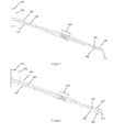
- Figure 4 shows a further instrument, comprising a first light source 101, second light source 102 and sample cell 105.
- the first light source 101 may be a coherent light source, such as a laser.
- the second light source may be incoherent, such as an LED.
- the first light source 101 is configured to illuminate a sample 150 within the sample cell 105 using a first light beam 121 along a first light beam axis, so as to produce scattered light 171, 173 by interaction of the first light beam 121 with particles of the sample 150.
- the scattered light comprises forward scattered light 171 and backward scattered light 173.
- the first light beam 121 passes through a first wall of the sample cell 105, then through the sample 150 and then through the second wall of the sample cell 105.
- the instrument further comprises a first detector 111 and third detector 113, configured to detect the scattered light 171, 173.
- the first detector 111 is arranged to detect forward scattered light 171
- the third detector 113 is arranged to detect backward scattered light 173.
- First collection lenses 181a, 181b are provided to collect and focus forward scattered light 171 at the first detector 111
- second collection lenses 183a, 183b are provided to collect and focus backward scattered light 173 at the third detector 113.
- the first detector 111 and third detector 113 are each positioned in different azimuthal locations (with respect to the first light beam axis).
- the first detector 111 and third detector 113 are at an azimuthal offset of 90°, so that if the first detector 111 receives S polarised scattered light, the second detector receives P polarised scattered light. This may substantially reduce the amount of optical noise at each of the first and third detector 111, 113 by positioning one of these detector away from reflections from the other detector.
- Each of the collection lenses 181a, 181b, 183a, 183b may comprise an aspheric surface.
- Each of the collection lenses 181a, 181b, 183a, 183b are sector shaped, when viewed along the first light beam axis, are positioned with their optical axes coincident with the first light beam axis, and comprise an open region to allow the first light beam 121 to pass by them without contributing to stray light by reflecting from the lenses 181a-b, 183a-b.
- This open region of each collecting lens substantially reduces optical noise, and means that reduced surface quality (contributing to light scattering) that may be associated with aspheric surfaces is less of an issue, since the first light beam 121 does not pass through the aspheric surface.
- the ability to use aspheric surfaces contributes significantly towards achieving a compact, high-performance scattered light detection arrangement.
- the first wall of the sample cell 105 may comprise a convex external surface 161 through which the first light beam 121 passes, and the second exterior wall of the sample cell 105 may comprise a convex external surface 162 through which the first light beam 121 passes.
- Each of the first and second wall may comprise a plano-convex lens, each comprising a flat internal sample cell surface.
- An effect of the curved external surfaces 161, 162 of the sample cell walls is to allow light scattered at higher angles to escape with less refraction at the sample cell air interface.
- Flat external surfaces result in spreading out of scattered light as it is refracted at the sample cell wall/air interface, and a critical angle exists at which scattered light is totally internally reflected.
- the use of a sample cell 105 with a convex external surface 161 or 162 enables both a broader range of scattering angles to be detected, increases the amount of scattered light per steradian outside the sample cell (because scattered light is not spread by refraction at the sample cell/ait interface) and reduces optical noise (because any totally internally reflected scattered light ends up as optical noise).
- the convex external walls 161, 162 decrease deleterious effects of detecting light from the sample cell 105 at high angles (relative to a normal to the plane defined by the interior surfaces of the sample cell 105), as well as increasing the range of angles over which light from the sample 150 may be detected. This makes it more straightforward to arrange multiple detection modalities around the sample cell 105 with different detection/imaging axes and different illumination axes (such as scattering detectors 111, 113 and imaging detector 112).
- Each of the first detector 111 and third detector 111, 113 may comprise an array of light sensitive elements, each element for detecting light scattered at a different range of angles.
- the first detector 111 may be configured to detect light scattered at angles of around 20° to around 70°.
- the range of scattering angles detected at the first detector 111 may include scattering angles that are higher than the critical angle for a flat walled cell.
- the range of scattering angles detected by the first detector 111 may be at least 30° (e.g. from 20° to 50°).
- a further detector (not shown) may be configured to detect lower scattering angles.
- the scattered light detected by the further detector may be focussed on the further detector by the second sample cell wall.
- the second detector 112 comprises an imaging detector.
- the plane of an imaging lens 182 is schematically illustrated in Figure 4 , showing how the sample 150 may be imaged at the second detector 112.
- the second light source 102 is configured to provide bright field illumination of the sample 150, and is configured to produce a second light beam 122 along a second light beam axis.
- the second light beam axis is substantially coincident with the imaging axis of the second detector 112, and the second light source 112 thereby provides bright field illumination of the sample 150.
- At least one lens may be provided between the second light source 102 and the sample cell 150.
- a collector lens 187 and condenser lens 188 are provided between the second light source 102 and the sample cell 105, so as to provide for a Köhler type optical arrangement in which substantially uniform illumination of the first region of the sample cell 105 is provided.
- Figure 5 shows a further example of scattering instrument, which is similar to that of Figure 4 .
- the schematic illustration imaging lens 182 have been replaced with a group of lens elements that together comprise the imaging lens 182, and the second detector 112 has been repositioned based on the design of the imaging lens 182.
- the second light source 102 and associated optics are the same as described with respect to Figure 4 , as is the sample cell 105, first detector 111 and associated collection lenses 181a, 181b, and the third detector 113 and associated collection lenses 183a, 183b.
- Figure 5 includes a further detector 111a, for detecting light scattered from the sample 150 at low forward scattering angles (i.e. at a range of scattering angles that includes angles smaller than the range of scattering angles received by the first detector 111).
- Light scattered by the interaction of the first light beam 121 with the sample 150 is focussed by the second sample cell wall 162 at the further detector 111a.
- the further detector 111a may be configured to detect light scattered at angles of less than 1° to angles of at least 10°, for instance, from 0.1° to 15°.
- Figure 6 illustrates the optical arrangement of the second sample cell wall 142, imaging lens 182 and second detector 112, showing the path of a first, second and third bundle of rays 191, 192, 193, corresponding with lower, mid and upper locations within the imaging region of the sample cell 105. This can be compared with a similar illustration for a sample cell with flat walls, shown in Figure 7 .
- a further benefit of the second sample cell wall 142 comprising a lens is that the image height, or numerical aperture of the imaging arrangement is increased. In example embodiments, and increase in numerical aperture of around 1.6 is possible.
- Figure 8 illustrates an example imaging optical arrangement which is similar to that of Figure 6 , in which a field flattener lens 189 has been included to at least partially compensate for the inclined imaging axis with respect to the sample cell 105. This may improve image quality at the second detector 112.
- the sample cell 105 may be in a different position than shown in Figures 4 and 5 .
- the sample cell optical axis may be aligned (or coincident with) the imaging axis of the second (imaging) detector 112. This may improve the quality with which the sample is imaged by the second detector 112.
- the scattering arrangement may be substantially unaffected by this change, due to the reduced refraction at the sample cell/air interfaces resulting from the convex cell surfaces 161, 162.
Priority Applications (3)
| Application Number | Priority Date | Filing Date | Title |
|---|---|---|---|
| EP15166133.7A EP3088863A1 (fr) | 2015-05-01 | 2015-05-01 | Améliorations se rapportant à la caractérisation de particules |
| US15/139,128 US9897525B2 (en) | 2015-05-01 | 2016-04-26 | Relating to particle characterisation |
| US16/216,085 USRE49651E1 (en) | 2015-05-01 | 2018-12-11 | Apparatus for characterizing particles and method for use in characterizing particles |
Applications Claiming Priority (1)
| Application Number | Priority Date | Filing Date | Title |
|---|---|---|---|
| EP15166133.7A EP3088863A1 (fr) | 2015-05-01 | 2015-05-01 | Améliorations se rapportant à la caractérisation de particules |
Publications (1)
| Publication Number | Publication Date |
|---|---|
| EP3088863A1 true EP3088863A1 (fr) | 2016-11-02 |
Family
ID=53015737
Family Applications (1)
| Application Number | Title | Priority Date | Filing Date |
|---|---|---|---|
| EP15166133.7A Withdrawn EP3088863A1 (fr) | 2015-05-01 | 2015-05-01 | Améliorations se rapportant à la caractérisation de particules |
Country Status (2)
| Country | Link |
|---|---|
| US (2) | US9897525B2 (fr) |
| EP (1) | EP3088863A1 (fr) |
Cited By (3)
| Publication number | Priority date | Publication date | Assignee | Title |
|---|---|---|---|---|
| WO2019013912A1 (fr) * | 2017-07-14 | 2019-01-17 | Phoseon Technology, Inc. | Systèmes et procédés pour un détecteur d'absorbance avec référence optique |
| KR20200119200A (ko) * | 2019-04-09 | 2020-10-19 | 가부시끼가이샤 히다치 세이사꾸쇼 | 입자 사이즈 측정 장치 및 측정 방법 |
| JP2020173244A (ja) * | 2019-04-09 | 2020-10-22 | 株式会社日立製作所 | 粒子サイズ測定装置および測定方法 |
Families Citing this family (6)
| Publication number | Priority date | Publication date | Assignee | Title |
|---|---|---|---|---|
| FR3049348B1 (fr) * | 2016-03-23 | 2023-08-11 | Commissariat Energie Atomique | Procede de caracterisation d’une particule dans un echantillon |
| CN107421876B (zh) * | 2017-06-16 | 2023-05-16 | 中国人民解放军第五七一九工厂 | 一种油液颗粒计数器 |
| US11879822B2 (en) * | 2018-06-01 | 2024-01-23 | Horiba, Ltd. | Particle size distribution measuring device and program for particle size distribution measuring device |
| US10416060B1 (en) | 2019-06-04 | 2019-09-17 | Horiba Instruments Incorporated | Apparatus and method for three-dimensional dynamic image analysis for particle volume determination |
| KR20210012259A (ko) * | 2019-07-24 | 2021-02-03 | 삼성전자주식회사 | 미세먼지 측정 장치 및 방법 |
| FR3109159B1 (fr) * | 2020-04-09 | 2023-06-23 | Interscience | Procédé de traitement d’images appliqué aux compteurs de colonies en microbiologie |
Citations (5)
| Publication number | Priority date | Publication date | Assignee | Title |
|---|---|---|---|---|
| EP0559529A1 (fr) * | 1992-03-04 | 1993-09-08 | Compagnie Industrielle Des Lasers Cilas | Granulomètre à laser |
| US20050105077A1 (en) * | 2000-08-02 | 2005-05-19 | Aravind Padmanabhan | Miniaturized cytometer for detecting multiple species in a sample |
| US20070146873A1 (en) * | 2005-12-09 | 2007-06-28 | Amnis Corporation | Extended depth of field imaging for high speed object analysis |
| WO2013027034A1 (fr) * | 2011-08-19 | 2013-02-28 | Malvern Instruments Limited | Caractérisation double mode de matières particulaires |
| WO2013173446A1 (fr) * | 2012-05-15 | 2013-11-21 | 1087 Systems, Inc. | Système cytométrique à fonction de mesure interférométrique |
Family Cites Families (22)
| Publication number | Priority date | Publication date | Assignee | Title |
|---|---|---|---|---|
| DE2832091A1 (de) * | 1978-07-21 | 1980-01-31 | Eidenschink Henning | Optisches verfahren zur bestimmung der teilchengroesse kolloidaler loesungen und messgeraet zur durchfuehrung des verfahrens |
| US5104221A (en) * | 1989-03-03 | 1992-04-14 | Coulter Electronics Of New England, Inc. | Particle size analysis utilizing polarization intensity differential scattering |
| JP3111706B2 (ja) * | 1992-02-18 | 2000-11-27 | 株式会社日立製作所 | 粒子分析装置及び粒子分析方法 |
| US5416580A (en) * | 1993-07-07 | 1995-05-16 | General Signal Corporation | Methods and apparatus for determining small particle size distribution utilizing multiple light beams |
| DE69533469T2 (de) * | 1994-12-26 | 2005-09-22 | Sysmex Corp. | Durchflusszytometer |
| JP3650265B2 (ja) * | 1997-05-27 | 2005-05-18 | オリンパス株式会社 | 光学機械の照明装置 |
| DE19802141C1 (de) * | 1998-01-22 | 1999-04-22 | Retsch Kurt Gmbh & Co Kg | Vorrichtung zur Bestimmung der Partikelgrößenverteilung eines Partikelgemisches |
| GB9818351D0 (en) * | 1998-08-22 | 1998-10-14 | Malvern Instr Ltd | Improvements relating to the measurement of particle size distribution |
| JP2000146817A (ja) | 1998-11-12 | 2000-05-26 | Nikkiso Co Ltd | 粒度分布測定装置 |
| US6236458B1 (en) * | 1998-11-20 | 2001-05-22 | Horiba, Ltd. | Particle size distribution measuring apparatus, including an array detector and method of manufacturing the array detector |
| US6859276B2 (en) * | 2003-01-24 | 2005-02-22 | Coulter International Corp. | Extracted polarization intensity differential scattering for particle characterization |
| CA2487233C (fr) * | 2003-11-10 | 2014-05-13 | Frederick David King | Methode et appareil pour la mesure de particules au moyen de l'imagerie optique |
| WO2005091970A2 (fr) | 2004-03-06 | 2005-10-06 | Michael Trainer | Procedes et dispositif de determination de la taille et de la forme de particules |
| US9297737B2 (en) * | 2004-03-06 | 2016-03-29 | Michael Trainer | Methods and apparatus for determining characteristics of particles |
| JP2009501903A (ja) * | 2005-07-12 | 2009-01-22 | サルトン,スコット,エイチ. | 流体中粒子探知用の高開口数散光計器 |
| US20110189714A1 (en) * | 2010-02-03 | 2011-08-04 | Ayliffe Harold E | Microfluidic cell sorter and method |
| WO2009073649A1 (fr) * | 2007-12-04 | 2009-06-11 | Particle Measuring Systems, Inc. | Systèmes et procédés de détection de particules non orthogonaux |
| EP2322911A1 (fr) | 2009-11-13 | 2011-05-18 | Bühler AG | Dispositif de détermination de tailles de particules |
| US8681215B2 (en) * | 2011-04-29 | 2014-03-25 | ProteinSimple | Method and particle analyzer for determining a broad particle size distribution |
| GB2493391B (en) * | 2011-08-05 | 2015-09-16 | Malvern Instr Ltd | Optical detection and analysis of particles |
| GB2494735B (en) * | 2011-09-14 | 2017-10-25 | Malvern Instr Ltd | Apparatus for measuring particle-size distribution by light scattering |
| US10048187B2 (en) * | 2013-11-05 | 2018-08-14 | Malvern Panalytical Limited | Improvements relating to particle characterisation |
-
2015
- 2015-05-01 EP EP15166133.7A patent/EP3088863A1/fr not_active Withdrawn
-
2016
- 2016-04-26 US US15/139,128 patent/US9897525B2/en not_active Ceased
-
2018
- 2018-12-11 US US16/216,085 patent/USRE49651E1/en active Active
Patent Citations (5)
| Publication number | Priority date | Publication date | Assignee | Title |
|---|---|---|---|---|
| EP0559529A1 (fr) * | 1992-03-04 | 1993-09-08 | Compagnie Industrielle Des Lasers Cilas | Granulomètre à laser |
| US20050105077A1 (en) * | 2000-08-02 | 2005-05-19 | Aravind Padmanabhan | Miniaturized cytometer for detecting multiple species in a sample |
| US20070146873A1 (en) * | 2005-12-09 | 2007-06-28 | Amnis Corporation | Extended depth of field imaging for high speed object analysis |
| WO2013027034A1 (fr) * | 2011-08-19 | 2013-02-28 | Malvern Instruments Limited | Caractérisation double mode de matières particulaires |
| WO2013173446A1 (fr) * | 2012-05-15 | 2013-11-21 | 1087 Systems, Inc. | Système cytométrique à fonction de mesure interférométrique |
Non-Patent Citations (1)
| Title |
|---|
| "CHAPTER 4: How Flow Cytometers Work ED - Howard M Shapiro", 1 January 2003, PRACTICAL FLOW CYTOMETRY, WILEY-LISS, HOBOKEN, NJ, PAGE(S) 101 - 223, ISBN: 978-0-471-41125-3, XP009145731 * |
Cited By (11)
| Publication number | Priority date | Publication date | Assignee | Title |
|---|---|---|---|---|
| WO2019013912A1 (fr) * | 2017-07-14 | 2019-01-17 | Phoseon Technology, Inc. | Systèmes et procédés pour un détecteur d'absorbance avec référence optique |
| US10274369B2 (en) | 2017-07-14 | 2019-04-30 | Phoseon Technology, Inc. | Systems and methods for an absorbance detector with optical reference |
| CN111051858A (zh) * | 2017-07-14 | 2020-04-21 | 锋翔科技公司 | 基于光学参考的吸光度检测方法及系统 |
| JP2020526770A (ja) * | 2017-07-14 | 2020-08-31 | フォセオン テクノロジー, インコーポレイテッドPhoseon Technology, Inc. | 光学基準を備えた吸光度検出器のためのシステムおよび方法 |
| US10876893B2 (en) | 2017-07-14 | 2020-12-29 | Phoseon Technology, Inc. | Systems and methods for an absorbance detector with optical reference |
| US11513006B2 (en) | 2017-07-14 | 2022-11-29 | Phoseon Technology, Inc. | Systems and methods for an absorbance detector with optical reference |
| KR20200119200A (ko) * | 2019-04-09 | 2020-10-19 | 가부시끼가이샤 히다치 세이사꾸쇼 | 입자 사이즈 측정 장치 및 측정 방법 |
| JP2020173244A (ja) * | 2019-04-09 | 2020-10-22 | 株式会社日立製作所 | 粒子サイズ測定装置および測定方法 |
| EP3722780A3 (fr) * | 2019-04-09 | 2020-12-23 | Hitachi, Ltd. | Appareil de mesure de la taille de particules et procédé de mesure |
| KR102333898B1 (ko) | 2019-04-09 | 2021-12-01 | 가부시끼가이샤 히다치 세이사꾸쇼 | 입자 사이즈 측정 장치 및 측정 방법 |
| US11385156B2 (en) | 2019-04-09 | 2022-07-12 | Hitachi, Ltd. | Particle size measuring apparatus and measuring method |
Also Published As
| Publication number | Publication date |
|---|---|
| USRE49651E1 (en) | 2023-09-12 |
| US20160320284A1 (en) | 2016-11-03 |
| US9897525B2 (en) | 2018-02-20 |
Similar Documents
| Publication | Publication Date | Title |
|---|---|---|
| USRE49651E1 (en) | Apparatus for characterizing particles and method for use in characterizing particles | |
| US7471393B2 (en) | Methods and apparatus for determining the size and shape of particles | |
| JP6691043B2 (ja) | 粒子特性評価装置 | |
| US20070242269A1 (en) | Methods and apparatus for determining characteristics of particles | |
| US20080204716A1 (en) | Methods and apparatus for determining characteristics of particles | |
| US4690561A (en) | Particle analyzing apparatus | |
| JP7420551B2 (ja) | 粒子測定装置 | |
| US7379577B2 (en) | Method and apparatus for particle measurement employing optical imaging | |
| CN109342028A (zh) | 衍射光学元件检测方法与系统 | |
| CN107490851B (zh) | 手术显微镜左右变倍系统的光学检测装置及方法 | |
| JP2022172075A (ja) | 落射蛍光測定用の光学フローサイトメータ | |
| US10697884B2 (en) | Image cytometer implementation | |
| US20180045646A1 (en) | System and method for three-dimensional micro particle tracking | |
| JP2008026049A (ja) | フランジ焦点距離測定装置 | |
| JPH0213830A (ja) | 粒子測定装置 | |
| JPH06508218A (ja) | 広い測定範囲を有する偏向型光学装置 | |
| KR20120056948A (ko) | 마이크로 렌즈 어레이를 이용한 공초점 측정 장치 | |
| JPS61167838A (ja) | 粒子解析装置 | |
| EP4009039A1 (fr) | Procédé et système d'observer de particules sur a surface | |
| CN117538333A (zh) | 镜头阵列和晶圆检测设备 | |
| SU798552A1 (ru) | Способ определени размеров сферичес-КиХ МиКРОчАСТиц |
Legal Events
| Date | Code | Title | Description |
|---|---|---|---|
| PUAI | Public reference made under article 153(3) epc to a published international application that has entered the european phase |
Free format text: ORIGINAL CODE: 0009012 |
|
| AK | Designated contracting states |
Kind code of ref document: A1 Designated state(s): AL AT BE BG CH CY CZ DE DK EE ES FI FR GB GR HR HU IE IS IT LI LT LU LV MC MK MT NL NO PL PT RO RS SE SI SK SM TR |
|
| AX | Request for extension of the european patent |
Extension state: BA ME |
|
| STAA | Information on the status of an ep patent application or granted ep patent |
Free format text: STATUS: THE APPLICATION IS DEEMED TO BE WITHDRAWN |
|
| 18D | Application deemed to be withdrawn |
Effective date: 20170503 |