EP3087894B2 - Beweglicher roboter und steuerungsverfahren dafür - Google Patents
Beweglicher roboter und steuerungsverfahren dafür Download PDFInfo
- Publication number
- EP3087894B2 EP3087894B2 EP16158683.9A EP16158683A EP3087894B2 EP 3087894 B2 EP3087894 B2 EP 3087894B2 EP 16158683 A EP16158683 A EP 16158683A EP 3087894 B2 EP3087894 B2 EP 3087894B2
- Authority
- EP
- European Patent Office
- Prior art keywords
- robot cleaner
- obstacle
- controller
- main body
- distance
- Prior art date
- Legal status (The legal status is an assumption and is not a legal conclusion. Google has not performed a legal analysis and makes no representation as to the accuracy of the status listed.)
- Active
Links
- 238000000034 method Methods 0.000 title claims description 34
- 230000003247 decreasing effect Effects 0.000 claims description 9
- 230000007423 decrease Effects 0.000 claims description 7
- 230000008569 process Effects 0.000 claims description 3
- 238000004140 cleaning Methods 0.000 description 55
- 238000004891 communication Methods 0.000 description 36
- 239000000428 dust Substances 0.000 description 16
- 230000008859 change Effects 0.000 description 13
- 230000003287 optical effect Effects 0.000 description 9
- 239000000463 material Substances 0.000 description 8
- 230000009467 reduction Effects 0.000 description 5
- 230000004044 response Effects 0.000 description 5
- 238000004378 air conditioning Methods 0.000 description 4
- 230000006870 function Effects 0.000 description 3
- 230000005389 magnetism Effects 0.000 description 3
- 238000013459 approach Methods 0.000 description 2
- 238000010586 diagram Methods 0.000 description 2
- 238000010438 heat treatment Methods 0.000 description 2
- 238000009434 installation Methods 0.000 description 2
- 239000002184 metal Substances 0.000 description 2
- 230000001133 acceleration Effects 0.000 description 1
- 230000004075 alteration Effects 0.000 description 1
- 238000001816 cooling Methods 0.000 description 1
- 230000001419 dependent effect Effects 0.000 description 1
- 238000001514 detection method Methods 0.000 description 1
- 238000001914 filtration Methods 0.000 description 1
- 230000005283 ground state Effects 0.000 description 1
- 230000036541 health Effects 0.000 description 1
- 239000004973 liquid crystal related substance Substances 0.000 description 1
- 238000012423 maintenance Methods 0.000 description 1
- 238000005259 measurement Methods 0.000 description 1
- 238000012986 modification Methods 0.000 description 1
- 230000004048 modification Effects 0.000 description 1
- 239000004745 nonwoven fabric Substances 0.000 description 1
- 238000011017 operating method Methods 0.000 description 1
- 230000002093 peripheral effect Effects 0.000 description 1
- 230000002265 prevention Effects 0.000 description 1
- 238000002310 reflectometry Methods 0.000 description 1
- 238000007789 sealing Methods 0.000 description 1
- 239000004065 semiconductor Substances 0.000 description 1
- 230000035945 sensitivity Effects 0.000 description 1
- 229920003051 synthetic elastomer Polymers 0.000 description 1
- 239000005061 synthetic rubber Substances 0.000 description 1
- 238000011144 upstream manufacturing Methods 0.000 description 1
- XLYOFNOQVPJJNP-UHFFFAOYSA-N water Substances O XLYOFNOQVPJJNP-UHFFFAOYSA-N 0.000 description 1
Images


Classifications
-
- G—PHYSICS
- G05—CONTROLLING; REGULATING
- G05D—SYSTEMS FOR CONTROLLING OR REGULATING NON-ELECTRIC VARIABLES
- G05D1/00—Control of position, course or altitude of land, water, air, or space vehicles, e.g. automatic pilot
- G05D1/02—Control of position or course in two dimensions
- G05D1/021—Control of position or course in two dimensions specially adapted to land vehicles
- G05D1/0231—Control of position or course in two dimensions specially adapted to land vehicles using optical position detecting means
- G05D1/0238—Control of position or course in two dimensions specially adapted to land vehicles using optical position detecting means using obstacle or wall sensors
-
- A—HUMAN NECESSITIES
- A47—FURNITURE; DOMESTIC ARTICLES OR APPLIANCES; COFFEE MILLS; SPICE MILLS; SUCTION CLEANERS IN GENERAL
- A47L—DOMESTIC WASHING OR CLEANING; SUCTION CLEANERS IN GENERAL
- A47L9/00—Details or accessories of suction cleaners, e.g. mechanical means for controlling the suction or for effecting pulsating action; Storing devices specially adapted to suction cleaners or parts thereof; Carrying-vehicles specially adapted for suction cleaners
- A47L9/009—Carrying-vehicles; Arrangements of trollies or wheels; Means for avoiding mechanical obstacles
-
- A—HUMAN NECESSITIES
- A47—FURNITURE; DOMESTIC ARTICLES OR APPLIANCES; COFFEE MILLS; SPICE MILLS; SUCTION CLEANERS IN GENERAL
- A47L—DOMESTIC WASHING OR CLEANING; SUCTION CLEANERS IN GENERAL
- A47L11/00—Machines for cleaning floors, carpets, furniture, walls, or wall coverings
- A47L11/40—Parts or details of machines not provided for in groups A47L11/02 - A47L11/38, or not restricted to one of these groups, e.g. handles, arrangements of switches, skirts, buffers, levers
- A47L11/4011—Regulation of the cleaning machine by electric means; Control systems and remote control systems therefor
-
- A—HUMAN NECESSITIES
- A47—FURNITURE; DOMESTIC ARTICLES OR APPLIANCES; COFFEE MILLS; SPICE MILLS; SUCTION CLEANERS IN GENERAL
- A47L—DOMESTIC WASHING OR CLEANING; SUCTION CLEANERS IN GENERAL
- A47L9/00—Details or accessories of suction cleaners, e.g. mechanical means for controlling the suction or for effecting pulsating action; Storing devices specially adapted to suction cleaners or parts thereof; Carrying-vehicles specially adapted for suction cleaners
- A47L9/28—Installation of the electric equipment, e.g. adaptation or attachment to the suction cleaner; Controlling suction cleaners by electric means
- A47L9/2805—Parameters or conditions being sensed
- A47L9/2826—Parameters or conditions being sensed the condition of the floor
-
- A—HUMAN NECESSITIES
- A47—FURNITURE; DOMESTIC ARTICLES OR APPLIANCES; COFFEE MILLS; SPICE MILLS; SUCTION CLEANERS IN GENERAL
- A47L—DOMESTIC WASHING OR CLEANING; SUCTION CLEANERS IN GENERAL
- A47L9/00—Details or accessories of suction cleaners, e.g. mechanical means for controlling the suction or for effecting pulsating action; Storing devices specially adapted to suction cleaners or parts thereof; Carrying-vehicles specially adapted for suction cleaners
- A47L9/28—Installation of the electric equipment, e.g. adaptation or attachment to the suction cleaner; Controlling suction cleaners by electric means
- A47L9/2836—Installation of the electric equipment, e.g. adaptation or attachment to the suction cleaner; Controlling suction cleaners by electric means characterised by the parts which are controlled
- A47L9/2852—Elements for displacement of the vacuum cleaner or the accessories therefor, e.g. wheels, casters or nozzles
-
- A—HUMAN NECESSITIES
- A47—FURNITURE; DOMESTIC ARTICLES OR APPLIANCES; COFFEE MILLS; SPICE MILLS; SUCTION CLEANERS IN GENERAL
- A47L—DOMESTIC WASHING OR CLEANING; SUCTION CLEANERS IN GENERAL
- A47L9/00—Details or accessories of suction cleaners, e.g. mechanical means for controlling the suction or for effecting pulsating action; Storing devices specially adapted to suction cleaners or parts thereof; Carrying-vehicles specially adapted for suction cleaners
- A47L9/28—Installation of the electric equipment, e.g. adaptation or attachment to the suction cleaner; Controlling suction cleaners by electric means
- A47L9/2868—Arrangements for power supply of vacuum cleaners or the accessories thereof
- A47L9/2884—Details of arrangements of batteries or their installation
-
- A—HUMAN NECESSITIES
- A47—FURNITURE; DOMESTIC ARTICLES OR APPLIANCES; COFFEE MILLS; SPICE MILLS; SUCTION CLEANERS IN GENERAL
- A47L—DOMESTIC WASHING OR CLEANING; SUCTION CLEANERS IN GENERAL
- A47L9/00—Details or accessories of suction cleaners, e.g. mechanical means for controlling the suction or for effecting pulsating action; Storing devices specially adapted to suction cleaners or parts thereof; Carrying-vehicles specially adapted for suction cleaners
- A47L9/28—Installation of the electric equipment, e.g. adaptation or attachment to the suction cleaner; Controlling suction cleaners by electric means
- A47L9/2894—Details related to signal transmission in suction cleaners
-
- G—PHYSICS
- G01—MEASURING; TESTING
- G01S—RADIO DIRECTION-FINDING; RADIO NAVIGATION; DETERMINING DISTANCE OR VELOCITY BY USE OF RADIO WAVES; LOCATING OR PRESENCE-DETECTING BY USE OF THE REFLECTION OR RERADIATION OF RADIO WAVES; ANALOGOUS ARRANGEMENTS USING OTHER WAVES
- G01S15/00—Systems using the reflection or reradiation of acoustic waves, e.g. sonar systems
- G01S15/87—Combinations of sonar systems
- G01S15/876—Combination of several spaced transmitters or receivers of known location for determining the position of a transponder or a reflector
-
- G—PHYSICS
- G01—MEASURING; TESTING
- G01S—RADIO DIRECTION-FINDING; RADIO NAVIGATION; DETERMINING DISTANCE OR VELOCITY BY USE OF RADIO WAVES; LOCATING OR PRESENCE-DETECTING BY USE OF THE REFLECTION OR RERADIATION OF RADIO WAVES; ANALOGOUS ARRANGEMENTS USING OTHER WAVES
- G01S15/00—Systems using the reflection or reradiation of acoustic waves, e.g. sonar systems
- G01S15/88—Sonar systems specially adapted for specific applications
- G01S15/93—Sonar systems specially adapted for specific applications for anti-collision purposes
- G01S15/931—Sonar systems specially adapted for specific applications for anti-collision purposes of land vehicles
-
- G—PHYSICS
- G01—MEASURING; TESTING
- G01S—RADIO DIRECTION-FINDING; RADIO NAVIGATION; DETERMINING DISTANCE OR VELOCITY BY USE OF RADIO WAVES; LOCATING OR PRESENCE-DETECTING BY USE OF THE REFLECTION OR RERADIATION OF RADIO WAVES; ANALOGOUS ARRANGEMENTS USING OTHER WAVES
- G01S7/00—Details of systems according to groups G01S13/00, G01S15/00, G01S17/00
- G01S7/52—Details of systems according to groups G01S13/00, G01S15/00, G01S17/00 of systems according to group G01S15/00
- G01S7/54—Details of systems according to groups G01S13/00, G01S15/00, G01S17/00 of systems according to group G01S15/00 with receivers spaced apart
-
- G—PHYSICS
- G05—CONTROLLING; REGULATING
- G05D—SYSTEMS FOR CONTROLLING OR REGULATING NON-ELECTRIC VARIABLES
- G05D1/00—Control of position, course or altitude of land, water, air, or space vehicles, e.g. automatic pilot
- G05D1/0088—Control of position, course or altitude of land, water, air, or space vehicles, e.g. automatic pilot characterized by the autonomous decision making process, e.g. artificial intelligence, predefined behaviours
-
- G—PHYSICS
- G05—CONTROLLING; REGULATING
- G05D—SYSTEMS FOR CONTROLLING OR REGULATING NON-ELECTRIC VARIABLES
- G05D1/00—Control of position, course or altitude of land, water, air, or space vehicles, e.g. automatic pilot
- G05D1/02—Control of position or course in two dimensions
- G05D1/021—Control of position or course in two dimensions specially adapted to land vehicles
- G05D1/0231—Control of position or course in two dimensions specially adapted to land vehicles using optical position detecting means
- G05D1/0242—Control of position or course in two dimensions specially adapted to land vehicles using optical position detecting means using non-visible light signals, e.g. IR or UV signals
-
- G—PHYSICS
- G05—CONTROLLING; REGULATING
- G05D—SYSTEMS FOR CONTROLLING OR REGULATING NON-ELECTRIC VARIABLES
- G05D1/00—Control of position, course or altitude of land, water, air, or space vehicles, e.g. automatic pilot
- G05D1/02—Control of position or course in two dimensions
- G05D1/021—Control of position or course in two dimensions specially adapted to land vehicles
- G05D1/0268—Control of position or course in two dimensions specially adapted to land vehicles using internal positioning means
- G05D1/027—Control of position or course in two dimensions specially adapted to land vehicles using internal positioning means comprising intertial navigation means, e.g. azimuth detector
-
- A—HUMAN NECESSITIES
- A47—FURNITURE; DOMESTIC ARTICLES OR APPLIANCES; COFFEE MILLS; SPICE MILLS; SUCTION CLEANERS IN GENERAL
- A47L—DOMESTIC WASHING OR CLEANING; SUCTION CLEANERS IN GENERAL
- A47L2201/00—Robotic cleaning machines, i.e. with automatic control of the travelling movement or the cleaning operation
- A47L2201/02—Docking stations; Docking operations
- A47L2201/022—Recharging of batteries
-
- A—HUMAN NECESSITIES
- A47—FURNITURE; DOMESTIC ARTICLES OR APPLIANCES; COFFEE MILLS; SPICE MILLS; SUCTION CLEANERS IN GENERAL
- A47L—DOMESTIC WASHING OR CLEANING; SUCTION CLEANERS IN GENERAL
- A47L2201/00—Robotic cleaning machines, i.e. with automatic control of the travelling movement or the cleaning operation
- A47L2201/04—Automatic control of the travelling movement; Automatic obstacle detection
Definitions
- the present disclosure relates to a moving robot and a controlling method thereof, and more particularly, to a robot cleaner and a controlling method thereof.
- robots have been developed for industrial purposes to play a role in factory automation. Recently, application fields of robots have extended, and robots for medical purpose, space navigation robots, etc., and even home robots available that may be used in general houses have been developed.
- a representative example of home robots is a robot cleaner.
- the robot cleaner is a type of an electronic device that sucks dust or foreign materials therearound while traveling in a certain region.
- the robot cleaner generally includes a rechargeable battery and an obstacle sensor for avoiding a hindrance or an obstacle during traveling. Thus, the robot cleaner can perform cleaning while traveling by itself.
- EP 2 325 714 A2 discloses a control method of a robot cleaner in which a robot cleaner is moved at an arbitrary starting angle along a rotation trajectory having an arbitrary rotational center and rotation radius during obstacle-following traveling.
- US 2009/048727 A1 discloses a robot cleaner and a control method of the same.
- the robot cleaner includes an obstacle sensor to sense an obstacle, a memory to store a local map, and a control unit to calculate an obstacle position using the obstacle sensor and to reflect the obstacle position around the robot cleaner on the local map.
- WO 01/91623 A2 discloses an autonomous mobile surface treating apparatus.
- an object of the present invention is to provide a robot cleaner and a controlling method thereof, which can prevent collision of the robot cleaner with an obstacle.
- Another object of the present invention is to provide a robot cleaner and a controlling method thereof, which can perform an avoidance operation with respect to an obstacle without any influence of friction between the floor and driving wheels of the robot cleaner and a sensor error of the robot cleaner.
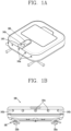
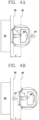
- FIGS. 1A to 1C are respectively perspective, front, and rear views illustrating external appearances of a robot cleaner according to an exemplary embodiment.
- the robot cleaner 100 may include a cleaning unit 190 ( Fig. 1E ) to suck and clean dust or foreign materials.
- the cleaning unit 190 further includes a rotary brush 191 rotatably mounted at a lower portion of a main body of the robot cleaner 100, and side brushes 192; 192a, 192b for cleaning edges or corners in a cleaning region such as a wall surface while rotating about a vertical rotational axis of the main body of the robot cleaner 100.
- the rotary brush 191 allows dust on a floor or carpet to be floated in the air while rotating about a horizontal axis of the main body of the robot cleaner.
- a plurality of blades are spirally provided on the outer circumferential surface of the rotary brush 191. Brushes may be provided between the spiral blades. Since the rotary brush 191 and the side brushes 192 have different rotational axes, the robot cleaner is generally to be provided with motors for respectively driving the rotary bush and the side brushes.
- the side brushes 192 may be disposed at both sides of the rotary brush 191, and an electromotive means for transmitting rotary power of the rotary brush 191 to the side brushes 192 may be provided between the rotary brush 191 and the side brushes 192, so that the rotary brush 191 and the side brushes 192 can all be driven by using one brush motor.
- a worm and a worm gear may be used as the electromotive means, or a belt may be used as the electromotive means.
- the cleaning unit 190 includes a dust container 195 for storing collected dust, a suction fan 196 for providing power for sucking dust in a cleaning region, and a suction motor 197 for sucking air by rotating the suction fan 196.
- a dust container 195 for storing collected dust
- a suction fan 196 for providing power for sucking dust in a cleaning region
- a suction motor 197 for sucking air by rotating the suction fan 196.
- the cleaning unit 190 can suck dust or foreign materials therearound.
- the suction fan 196 includes a plurality of wings for allowing air to flow, and a member formed in a ring shape at the upstream periphery of the plurality of wings to connect the plurality of wings to each other, the member guiding air flowed into the suction fan in the central axial direction of the suction fan to be flowed in a direction perpendicular to the central axis of the suction fan.
- the cleaning unit 190 is formed in an approximately rectangular parallelepiped shape, and may further include a filter 198 for filtering dirt or dust in the air.
- the filter 198 may be divided into a first filter and a second filter, when necessary, and a bypass filter may also be formed in a main body constituting the filter 198.
- the first filter and the second filter may be mesh filters or HEPA filters.
- the first filter and the second filter may be formed as one of a non-woven filter, a paper filter, and the like, or use together two or more thereof.
- a controller 180 may sense a state of the dust container 195. Specifically, the controller 180 may sense a state how much dust is contained in the dust container 195 and a state whether the dust container 195 is attached to or detached from the robot cleaner. In the former case, the state may be sensed by inserting a piezoelectric sensor, etc. into the dust container. In the latter case, the state may be sensed, in various forms.
- a micro-switch installed at the bottom surface of a groove having the dust container mounted therein to be turned on/off, a magnetic sensor using the magnetic field of a magnet, an optical sensor having a light emitting portion and a light receiving portion to receive light, and the like may be used as a sensor for sensing whether the dust container 195 is attached to or detached from the robot cleaner.
- a sealing member made of a synthetic rubber material may be further provided at a portion to which the magnet is adhered.
- the cleaning unit 190 may further include a dustcloth plate 199 separably mounted at a lower portion of the main body of the robot cleaner.
- the dustcloth plate 199 may include a dustcloth separably mounted thereto, and a user may separate the dustcloth from the dustcloth plate 199 to wash or replace the dustcloth.
- the dustcloth may be mounted in various manners, but attached to the dustcloth plate 199 by using non-woven fabric called "Velcro."
- the dustcloth plate 199 is mounted to the main body of the robot cleaner by magnetism of the main body of the robot cleaner.
- a first magnet may be provided in the dustcloth plate 199, and a metal member or second magnet corresponding to the first magnet may be provided in the main body of the robot cleaner. If the dustcloth plate 199 is normally located at the bottom of the main body of the robot cleaner, the dustcloth plate 199 is fixed to the main body of the robot cleaner by the first magnet and the metal member or the first and second magnets.
- the robot cleaner may further include a sensor for sensing whether the dustcloth plate 199 is mounted to the main body of the robot cleaner.
- the sensor may be a lead switch operated by magnetism, a hall sensor, or the like.
- the lead switch provided to the main body of the robot cleaner may be operated to output a mounting signal to the controller 180.
- the robot cleaner 100 may include main wheels 131a and 131b respectively disposed at both left and right sides of a lower portion thereof such that the main body is movable.
- a driving unit 130 is connected to the left and right main wheels 131a and 131b, and includes a motor (e.g., a wheel motor) for rotating the main wheels 131a and 131b.
- the driving unit 130 drives the motor, to rotate or move the main body.
- the wheel motor is preferably provided in plurality to be respectively connected to the main wheels 131a and 131b.
- the plurality of wheel motors may be independently operated to individually control the main wheels 131a, 131b.
- the robot cleaner 100 may further include one or more auxiliary wheels 132a, and 132b disposed at the rear (bottom) thereof.
- the auxiliary wheels 132a, and 132b may assist the robot cleaner 100 to smoothly move by supporting the main body of the robot cleaner and minimizing friction between the bottom surface of the main body and a floor surface (surface to be cleaned).
- handles may be respectively provided at edges of lower portions of the main body, e.g., both sides of the main wheels 131a and 131b such that the user easily holds the robot cleaner.
- FIG. 1E is a block diagram illustrating a configuration of the robot cleaner according to the exemplary embodiment.
- the robot cleaner 100 may include at least one of a communication unit 110, an input unit 120, the driving unit 130, a sensing unit 140, an output unit 150, the power supply unit 160, a storage unit 170, the controller 180, and the cleaning unit 190, or combinations thereof.
- FIG. 1E the components shown in FIG. 1E are not essential, and therefore, it will be apparent that a robot cleaner having a larger number of components or a smaller number of components may be implemented.
- a robot cleaner having a larger number of components or a smaller number of components may be implemented.
- each of the components will be described.
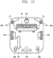
- the power supply unit 160 includes a battery 161 ( Fig. 1C ) rechargeable by external commercial power to supply power into the robot cleaner.
- the power supply unit 160 may supply driving power to each component included in the robot cleaner, thereby supplying operating power required when the robot cleaner travels or performs cleaning.
- the controller 180 may sense remaining power of the battery 161. If the remaining power is insufficient, the controller 180 may control the robot cleaner to move to a charging base connected to an external commercial power source, so that the battery 161 can be charged by receiving charging current supplied from the charging base.
- the battery 161 is connected to a battery sensing unit such that a remaining amount of the battery and a charging state of the battery can be transmitted to the controller 180. As shown in FIG. 1A , the controller 180 may control the output unit 150 to display the remaining amount of the battery on a screen.
- the battery 161 may be located at a lower portion of the center of the robot cleaner 100 or located at any one of left and right sides such that the dust container 195 is located at the lowermost end of the main body.
- the robot cleaner may further include a balance weight so as to prevent weight unbalance of the battery.
- the driving unit 130 includes motors and drives the motors, so that the left and right main wheels 131a and 131b are rotated in both directions, thereby rotating or moving the main body. Description of the driving unit 130 is replaced by the foregoing description, and detailed description of the driving unit 130 will be omitted.
- the input unit 120 receives various control commands on the robot cleaner, input from the user.
- the input unit 120 may include one or more buttons.
- the input unit 120 may include an OK button, a setting button, etc.
- the OK button is a button for receiving, from the user, sensing information, obstacle information, location information, or a command for confirming a cleaning area or a cleaning map.
- the setting button is a button for receiving, from the user, a command for setting the information.
- the input unit 120 may include an input reset button for canceling a previous user input and again receiving a user input, a delete button for deleting a previously set user input, a cleaning start button, a cleaning stop button, a reservation button for setting or deleting reservation information, a button for setting or changing a cleaning mode, a button for allowing the robot cleaner to return to the charging base, and the like.
- the input unit 120 may be installed as a hard key, a soft key, a touch pad, etc., at an upper portion of the robot cleaner. Also, the input unit 120 may have, together with the output unit 150, the form of a touch screen.
- the output unit 150 may be provided on the upper portion of the robot cleaner 100. It will be apparent that the installation position or installation form of the output unit 150 may vary.
- the output unit 150 as shown in FIG. 1F , may display, on a screen, reservation information, a battery state, and a cleaning method or a traveling method such as intensive cleaning, a space extension, or a zigzag operation.
- the output unit 150 may output internal state information of the robot cleaner, sensed by the sensing unit 140, e.g., a current state of each of the components included in the robot cleaner and a current cleaning state. Also, the output unit 150 may display, on a screen, external state information, obstacle information, location information, a cleaning area, a cleaning map, etc., sensed by the sensing unit 140.
- the output unit 150 may be configured as any one element among a light emitting diode (LED), a liquid crystal display (LCD), a plasma display panel (PDP), and an organic light emitting diode (OLED).
- LED light emitting diode
- LCD liquid crystal display
- PDP plasma display panel
- OLED organic light emitting diode
- the output unit 150 may further include a sound output means for acoustically outputting a process or result of an operation of the robot cleaner, which is performed by the controller 180.
- the output unit 150 may output a warning sound to the outside in response to a warning signal generated by the controller 180.
- the sound output means may be a means for outputting sounds, such as a beeper or a speaker.
- the output unit 150 may output sounds to the outside through the sound output means by using audio data, message data, or the like, which has a predetermined pattern stored in the storage unit 170.
- the robot cleaner can output, on a screen or as a sound, a cleaning map and/or environment information on a cleaning area through the output unit 150.
- the robot cleaner may transmit the cleaning map and/or the environment information to a terminal device through a second communication unit such that the terminal device outputs a screen or sound to be output through the output unit 150.
- the controller 180 when environment information detected by an environment information detection unit is out of a predetermined range, the controller 180, as will be described later, can visually or acoustically output an alarm signal to the outside through the output unit 150. According to another exemplary embodiment, when it is decided that there exists environment information that is out of the predetermined range, the controller 180 may transmit the alarm signal to the terminal device, and the terminal device receiving the alarm signal may visually or acoustically output the alarm signal.
- the communication unit 110 is connected to the terminal device and/or another device (in this specification, will be used together with “electronic devices”) located in a cleaning area in one communication scheme among wired, wireless, and satellite communication schemes, to transmit/receive signals and data to/from the device.
- another device in this specification, will be used together with “electronic devices” located in a cleaning area in one communication scheme among wired, wireless, and satellite communication schemes, to transmit/receive signals and data to/from the device.
- the communication unit 110 may include a first communication unit and a second communication unit.
- the first communication unit and the second communication unit are divided according to a corresponding node transmitting/receiving data to/from the robot cleaner 100.
- the first communication unit and the second communication unit may use the same communication scheme.
- the first communication unit and the second communication unit may be configured as one module.
- the first communication unit may transmit/receive data to/from another device located in a cleaning area.
- the device may be any device that can transmit/receive data by being connected to a network.
- the device may be a device such as an air conditioning device, a heating device, an air purifying device, an electric lamp, a TV, or a car.
- the device may be a device for controlling a door, a window, a water supply valve, a gas supply valve, etc.
- the device may be a sensor, etc., which senses temperature, humidity, air pressure, gas, etc.
- the controller 180 can transmit a control signal to the device through the first communication unit, and accordingly, the device can operate in response to the received control signal.
- the device is an air conditioning device
- the air conditioning device may turn on power or perform cooling or heating on a cleaning area in response to a control signal.
- the device is a device for controlling a window
- the device may open/close the window or open the window at a certain rate in response to a control signal.
- the first communication unit may receive various state information, etc. from at least one device located in a cleaning area.
- the first communication unit may receive a setting temperature of the air conditioning device, opening/closing information representing whether the window is opened or closed or how much the window is opened, a current temperature of the cleaning area, sensed by a temperature sensor, etc.
- the controller 180 can generate a control signal for the device according to the state information, a user input through the input unit 120, or a user input through the terminal device.
- the first communication unit may employ at least one communication scheme among wireless communication schemes such as radio frequency (RF) communication, Bluetooth, infrared communication (IrDA), wireless LAN, and Zigbee.
- RF radio frequency
- IrDA infrared communication
- the device and the robot cleaner 100 can construct at least one network.
- the network is preferably Internet.
- the second communication unit may receive a control signal from the terminal device. Accordingly, the controller 180 can perform a command for creating a cleaning map, traveling in a cleaning area, performing cleaning, etc. in response to the control signal received through the second communication unit. For example, a control command to be input from the user through the input unit 120 may be received from the terminal device through the second communication unit, and the controller 180 may perform the received control command. Also, the second communication unit may transmit, to the terminal device, state information of the robot cleaner, obstacle information, location information, image information, a cleaning map, etc. For example, various information to be output through the output unit 150 may be transmitted to the terminal device through the second communication unit.
- the second communication unit may employ at least one communication scheme among wireless communication schemes such as radio frequency (RF) communication, Bluetooth, infrared communication (IrDA), wireless LAN, and Zigbee.
- RF radio frequency
- IrDA infrared communication
- the device and the robot cleaner 100 can construct at least one network.
- the network is preferably Internet.
- the robot cleaner 100 may communicate with the terminal device through the second communication unit using a communication scheme which the mobile terminal uses.
- the storage unit 170 stores a control program for controlling or driving the robot cleaner and data corresponding data.
- the storage unit 170 may store audio information, image information, obstacle information, location information, cleaning areas, cleaning maps, and the like. Also, the storage unit 170 may store cleaning method, traveling methods, and the like.
- a non-volatile memory is mainly used as the storage unit 170.
- the non-volatile memory (NVM, NVRAM) is a storage device capable of continuously maintaining stored information even when no power is supplied.
- the non-volatile memory may include ROM, a flash memory, a magnetic computer memory device (e.g., a hard disk, a diskette drive, and a magnetic tape), an optical disk drive, magnetic RAM, PRAM, etc.
- the sensing unit 140 may include at least one of an external signal sensor, a front sensor, a cliff sensor, a lower camera sensor, and an upper camera sensor.
- the external signal sensor may sense external signals of the robot cleaner.
- the external signal sensor may be an infrared ray sensor, an ultrasonic sensor, an RF sensor, etc.
- the robot cleaner may receive a guide signal generated from the charging base by using the external signal sensor, thereby checking a position and a direction of the charging base.
- the charging base may generate a guide signal instructing a direction and a distance thereof such that the robot cleaner can return to the charging base. That is, the robot cleaner receives the guide signal generated from the charging base to check a current position, and set a moving direction to return to the charging base.
- the robot cleaner may sense a signal generated from a remote control device, such as a remote controller or a terminal, by using the external signal sensor.
- a remote control device such as a remote controller or a terminal
- the external signal sensor may be provided inside or outside the robot cleaner.
- the infrared ray sensor may be installed inside the robot cleaner, below the output unit 150, or at the periphery of the upper camera sensor 141e.
- the front sensor is installed on a front surface of the robot cleaner, specifically, on a side circumferential surface with a predetermined gap therebetween.
- the front sensor is located on at least one surface of the robot cleaner to sense an obstacle located at the front of the robot cleaner.
- the front sensor may sense an object, particularly an obstacle in a moving direction of the robot cleaner, and transmit sensing information to the controller 180. That is, the front sensor may sense a protrusion, a home appliance, furniture, a wall surface, a wall edge, etc., which are disposed on a moving path of the robot cleaner, and transmits sensing information to the controller 180.
- the front sensor may be an infrared ray sensor, an ultrasonic sensor, an RF sensor, a terrestrial magnetism sensor, etc.
- the robot cleaner may use, as the front sensors, one type of sensors, or two or more types of sensors.
- the ultrasonic sensor 141a is generally used to sense an obstacle which is at a remote distance.
- the ultrasonic sensor 141a is provided with a signal transmitting portion and a signal receiving portion.
- the controller 180 may determine whether an obstacle exists based on whether an ultrasonic wave emitted from the signal transmitting portion has been received by the signal receiving portion after being reflected by an obstacle, etc. Then, the controller 180 may calculate a distance of the robot cleaner from the obstacle by using emission and reception times of the ultrasonic wave.
- the controller 180 may detect information related to the size of the obstacle by comparing the ultrasonic wave emitted from the signal transmitting portion with the ultrasonic wave received by the signal receiving portion. For example, the controller 180 may determine that the size of the obstacle becomes larger as a larger number of ultrasonic waves are received by the signal receiving portion.
- a plurality of (e.g., five) ultrasonic sensors 141a may be installed on a front outer circumferential surface of the robot cleaner.
- the supersonic sensors may be preferably provided with signal transmitting portions and signal receiving portions alternately installed on a front surface of the robot cleaner.
- the signal transmitting portions may be disposed at right and left sides based on the front center of the main body. Also, one or two or more signal transmitting portions are disposed between the signal receiving portions, thereby forming a reception region with respect to an ultrasonic signal reflected from an obstacle. Under this configuration, a reception region may be expanded in a state that the number of the sensors is reduced. An emitting angle of a supersonic wave may be maintained within a range not influencing on other signals for prevention of crosstalk. Reception sensitivities of the signal receiving portions may be differently set.
- the ultrasonic sensor may be installed toward an upper side by a predetermined angle such that an ultrasonic wave emitted from the ultrasonic sensor may be upwardly outputted.
- the ultrasonic sensor may further include a predetermined shielding member configured to prevent an ultrasonic wave from being downwardly emitted.
- the front sensor may use two or more types of sensors. Therefore, the front sensor may use any one type of sensors among an infrared sensor, an ultrasonic sensor, an RF sensor, and the like.
- the front sensor may include an infrared sensor 141b as another type of sensor, in addition to the ultrasonic sensor 141a.
- the infrared sensor 141b may be installed, together with the ultrasonic sensor 141a, on an outer circumferential surface of the robot cleaner.
- the infrared sensor 141b may also sense an object at a front or side of the robot cleaner, and transmit sensing information to the controller 180. That is, the infrared senor 141b may sense a protrusion, a home appliance, furniture, a wall surface, a wall edge, etc., which are disposed on a moving path of the robot cleaner, and transmits sensing information to the controller 180.
- the robot cleaner can move within a cleaning area without any collision of the main body with an obstacle.
- the cliff sensor is disposed on a bottom surface of the robot cleaner, and it will be apparent that the cliff sensor may be installed at another position according to a type of the robot cleaner.
- the cliff sensor is located on a bottom surface of the robot cleaner to sense an obstacle on the ground.
- the cliff sensor may be an infrared sensor having a signal transmitting portion and a signal receiving portion, an ultrasonic sensor, an RF sensor, a position sensitive detector (PSD) sensor, etc.
- one cliff sensor among cliff sensors 141c may be installed at a front surface of the robot cleaner, and two cliff sensors may be installed relatively behind the one cliff sensor.
- the arrangement of the cliff sensors 141c may be as follows. For convenience, it is assumed that the front cliff sensor is a first sensor, and the rear cliff sensor is a second sensor. Generally, the first and second sensors and may be implemented as the same type of sensors, e.g., PSD sensors. However, the first and second sensors and may be implemented as different types of sensors.
- the PSD sensor is implemented as one p-n junction device, and is configured to detect a distance of incident light by using a semiconductor surface resistance.
- the PSD sensor includes a primary PSD sensor configured to detect light in one direction, and a secondary PSD sensor configured to detect an optical position on a plane. Both of the primary PSD and the secondary PSD have a pin photodiode structure.
- the PSD sensor is a sort of infrared sensor.
- the PSD sensor is configured to sense an obstacle by emitting an infrared ray to the obstacle, and measure a distance of the robot cleaner from the obstacle, based on an angle of the infrared ray returning after reflection. That is, the PSD sensor calculates a distance of the robot cleaner from the obstacle by using a triangulation method.
- the PSD sensor is provided with a light transmitting portion configured to emit an infrared ray to an obstacle, and a light receiving portion configured to receive an infrared ray which returns after being reflected from the obstacle.
- the light transmitting portion and the light receiving portion are generally implemented in the form of a module.
- the PSD sensor can obtain stable measurement values regardless of reflectivity of an obstacle and a color difference.
- the controller 180 may control the first sensor to measure an angle between an emitting signal of an infrared ray emitted toward the ground and a reflecting signal received after being reflected by an obstacle, thereby sensing a cliff and analyzing a depth of the cliff.
- the controller 180 may determine whether the robot cleaner is to pass through a cliff sensed by using the first and second sensors and, based on a ground state of the sensed cliff. The controller 180 may determine whether the robot cleaner is to pass through the cliff, based on the determination result. As an example, the controller 180 may determine the presence of a cliff and a depth of the cliff through the first sensor and then control the robot cleaner to pass through the cliff only when a reflection signal is sensed by the second sensor.
- the controller 180 may determine whether the robot cleaner is in a levitated state by combining sensing results obtained by the first and second sensors and.
- the lower camera sensor 141d is provided on a rear surface of the robot cleaner, to acquire image information on the floor (or a surface to be cleaned) while the robot cleaner moves.
- the lower camera sensor may be called an 'optical flow sensor.'
- the lower camera sensor generates a predetermine type of image data by converting a down side image inputted from an image sensor provided therein.
- the generated image data may be stored in the storage unit 170.
- the lower camera sensor may be further provided with a lens (not shown) and a lens controller (not shown) for controlling the lens.
- a lens (not shown) and a lens controller (not shown) for controlling the lens.
- a pan focus type lens having a short focal distance and a deep depth may be used as the lens.
- the lens controller is provided with a predetermined motor for moving the lens back and forth, and a moving means, thereby controlling the lens.
- One or more optical sources may be installed near the image sensor.
- the one or more optical sources irradiate light onto a predetermined area of the floor captured by the image sensor. That is, if the floor along which the robot cleaner is moving is flat, a distance between the image sensor and the floor is constantly maintained. On the other hand, if the floor along which the robot cleaner is moving is not even, the distance between the image sensor and the floor becomes long due to a protrusion and an obstacle on the floor.
- the controller 180 may control the one or more optical sources to control the amount of light to be irradiated.
- the optical source may be a light emitting device capable of controlling an optical amount, e.g., a light emitting diode (LED), etc.
- the controller 180 may control the lower camera sensor 141d to sense a position of the robot cleaner regardless of sliding of the robot cleaner.
- the controller 180 may calculate a moving distance and a moving direction of the robot cleaner by analyzing image data captured by the lower camera sensor according to time, thereby calculating a position of the robot cleaner, based on the calculated moving distance and moving direction.
- image information on a lower side of the robot cleaner is acquired by using the lower camera sensor, a position of the robot cleaner having not been precisely calculated by another means due to sliding can be compensated under control of the controller 180.
- the upper camera sensor 141e may be installed toward an upper side or front side of the robot cleaner to capture the periphery of the robot cleaner.
- the upper camera sensors may be formed on an upper surface or side surfaces of the robot cleaner with a predetermined distance therebetween or with a predetermined angle.
- the upper camera sensor 141e may further include a lens for focusing the camera on a subject, a controller for controlling the camera sensor, and a lens controller for controlling the lens.
- the lens may be a lens having a wide view angle such that all the peripheral regions, e.g., all the regions on a ceiling can be captured at a predetermined position.
- the lens may include a lens having a view angle more than a predetermined angle, e.g., 160 degrees or more.
- the controller 180 may recognize a position of the robot cleaner, based on image data captured by the upper camera sensor, and create a map with respect to a cleaning area.
- the controller 180 may precisely recognize a position of the robot cleaner, based on image data acquired by an acceleration sensor, a gyro sensor, a wheel sensor, and the lower camera sensor, and image data acquired by the upper camera sensor.
- the controller 180 may create a cleaning map, based on obstacle information sensed by the front sensor or the obstacle sensor and a position of the robot cleaner, recognized by the upper camera sensor.
- the cleaning map is not created by the controller 180 but may be input from the outside and stored in the storage unit 170.
- the robot cleaner 100 performing an operation for preventing collision with an obstacle and a controlling method thereof will be described in conjunction with the robot cleaner 100 described in FIGS. 1A to 1F .
- the robot cleaner 100 and the controlling method thereof will be described, which can prevent collision with an obstacle existing in a traveling direction even when a braking distance is changed depending on friction between the driving unit 130 of the robot cleaner 100 and the floor.
- the robot cleaner 100 and the controlling method thereof will be described, which can prevent collision with an obstacle even when an error occurs in the sensing unit 140 of the robot cleaner 100.
- robot cleaner 100 and the controlling method thereof will be described, which can improve cleaning performance with respect to corner portions in a cleaning area while preventing collision with an obstacle located in the traveling direction of robot cleaner.
- FIG. 2 an exemplary embodiment of the controlling method of the robot cleaner 100 will be described.
- the driving unit 130 of the robot cleaner 100 may move the robot cleaner 100 (S201).
- the controller 180 may control the driving unit 130 such that the main body of the robot cleaner 100 is moved based on a predetermined traveling pattern.
- the controller 180 may control the driving unit 130 by using information related the traveling pattern stored in the storage unit 170. As another example, the controller 180 may control the driving unit 180 by using information related to the driving pattern, which is received from an external server, a terminal device, etc.
- the controller 180 may control the driving unit 130 to perform a zigzag operation on a predetermined cleaning area. That is, the controller 180 may control the driving unit 130 to perform a zigzag operation, based on a coordinate axis corresponding to the cleaning area.
- the sensing unit 140 may sense information related to an obstacle located in a moving direction of the robot cleaner 100 (S202).
- the sensing unit 140 may sense the information related to the obstacle at every predetermined time interval.
- the predetermined time interval may be determined according to attributes of the sensors included in the sensing unit 140.
- the predetermined time interval may be changed by a user.
- the ultrasonic sensor 141a included in the sensing unit 140 may sense information related to an obstacle located in a moving direction of the robot cleaner, based on the main body of the robot cleaner.
- the ultrasonic sensor 141a may be provided with the signal transmitting portion and the signal receiving portion.
- the controller 180 may determine whether an ultrasonic wave emitted from the signal transmitting portion has been received by the signal receiving portion after being reflected by an obstacle, etc., and calculate a distance of the robot cleaner from the obstacle by using emission and reception times of the ultrasonic wave.
- the controller 180 may detect information related to the size of the obstacle by comparing the ultrasonic wave emitted from the signal transmitting portion with the ultrasonic wave received by the signal receiving portion. For example, the controller 180 may determine that the size of the obstacle becomes larger as a larger number of ultrasonic waves are received by the signal receiving portion.
- the sensing unit 140 senses information related to an obstacle located in a moving direction of the robot cleaner, but the present disclosure is not limited thereto.
- the sensing unit 140 may sense information related to an obstacle located at the front/rear or left/right, based on the moving direction of the robot cleaner 100.
- the controller 180 may control the sensing unit 140 to sense information related to at least one portion of obstacles located in all directions of the robot cleaner 100, based on information related to a moving pattern of the robot cleaner 100.
- the controller 180 controls the driving unit 130 to reverse the robot cleaner 100 with respect to an obstacle, based on a distance between the robot cleaner 100 and the obstacle (S203).
- the controller 180 controls the driving unit 130 to reverse the main body.
- the controller 180 may calculate a distance between the obstacle and the robot cleaner 100 by using information related to the obstacle sensed by the sensing unit 140. If the sensing unit senses information related to the obstacle at every predetermined time interval, the controller 180 may calculate the distance between the obstacle and the robot cleaner 100, corresponding to the sensed information.
- the controller 180 may control the robot cleaner to be reversed with respect to the obstacle such that the distance between the robot cleaner 100 and the obstacle is increased. In this case, the controller 180 may control the driving unit 130 to reverse the robot cleaner 100 before an operation for preventing collision with the obstacle is performed.
- the controller 180 controls the driving unit 130 to reverse the robot cleaner 100 with respect to the obstacle.
- the controller 180 controls the driving unit 130 to reverse the robot cleaner 100 with respect to the obstacle.
- the first reference distance corresponds to a radius of rotation of the robot cleaner.
- the controller 180 may control the driving unit 130 such that a front surface of the main body is spaced apart from the obstacle at a predetermined gap or less.
- the predetermined gap may correspond to the radius of rotation.
- the radius of rotation may correspond to a distance from the rotational center of the robot cleaner to an outermost point of the robot cleaner.
- the radius of rotation may correspond to a distance from the rotational center of the robot cleaner to an outermost point of the main body of the robot cleaner.
- the radius of rotation may correspond to a distance from the rotational center of the robot cleaner to one end of the side brush 192.
- controller 180 may control the driving unit 130 to prevent collision between the robot cleaner and the obstacle (S204).
- the controller 180 may control the driving unit 130 to rotate the robot cleaner by a predetermined angle.
- the predetermined angle may be set to 90 degrees.
- a robot cleaner and a controlling method thereof which can prevent collision with an obstacle due to a change in braking distance of the robot cleaner or a sensor error according to a material of the floor.
- the robot cleaner and the controlling method according to the present disclosure when the distance from the rotational center of the robot cleaner to the periphery of the main body is not constant, it is possible to prevent collision with an obstacle while the moving direction of the robot cleaner is being changed with respect to the obstacle.
- FIG. 3A an exemplary embodiment of the robot cleaner for preventing collision with an obstacle and the controlling method thereof will be described.
- the driving unit 130 of the robot cleaner 100 may move (n1) the robot cleaner 100 in a specific direction.
- the driving unit 130 may perform a straight-ahead operation of the robot cleaner 100 such that the front surface of the main body of the robot cleaner 100 faces the moving direction of the robot cleaner 100.
- the sensing unit 140 may sense information related to an obstacle 300 at a predetermined time interval while the robot cleaner 100 is moving.
- controller 180 may calculate a distance between the robot cleaner 100 and the obstacle 300 by using the information related to the obstacle 300, which is sensed by the sensing unit 140.
- the controller 180 may calculate a distance from the obstacle 300 to the front surface of the main body by using the information sensed by the sensing unit 140, and calculate a distance from the obstacle 300 to the rotational center of the robot cleaner 100.
- the controller 180 may calculate a distance between the robot cleaner 100 and the obstacle 300 by using information related to the external appearance of the robot cleaner, which is stored in the storage unit 170.
- the information related to the external appearance of the robot cleaner may include a radius of rotation of the robot cleaner, a distance from the rotational center to the front surface of the main body, etc.
- the controller 180 may control the driving unit 130 to prevent collision of the robot controller with the obstacle. That is, the controller 180 may change the traveling direction of the robot cleaner, based on the calculated distance, to prevent collision of the robot cleaner with the obstacle.
- the controller 180 may change the traveling direction of the robot cleaner by a predetermined angle ⁇ . After that, the controller 180 controls the driving unit 130 to move (n2) the robot cleaner 100 in the changed direction, so that it is possible to prevent collision between the obstacle 300 and the robot cleaner 100.
- the predetermined angle ⁇ may be 90 degrees.
- the controller 180 may change the angle ⁇ at which the moving direction of the robot cleaner is changed, based on the information related to the obstacle 300. That is, the controller 180 may change the angle ⁇ at which the moving direction of the robot cleaner is changed, based on information related to the width of the obstacle 300 with respect to the movement n1.
- the controller 180 may change the angle ⁇ at which the moving direction of the robot cleaner is changed, based on a user input.
- FIG. 3B an exemplary embodiment of an operating method of the robot cleaner 100 according to a distance of the obstacle will be described in detail.
- the controller 180 may control the driving unit 130 to prevent collision between the obstacle 300 and the robot cleaner 100, based on a distance between the obstacle 300 and the robot cleaner 100.
- the controller 180 may control the driving unit 130 to decrease the moving speed of the robot cleaner 100.
- the controller 180 may perform a braking operation, thereby decreasing the moving speed of the robot cleaner 100.
- the controller 180 may reduce power supplied to the driving unit 130, thereby decreasing the moving speed of the robot cleaner 100.
- the controller 180 may set information related to the third reference distance 303 by using information related to a current speed or average speed of the robot cleaner. Also, the controller 180 may set the information related to the third reference distance 303 by using information related to friction between the floor in a cleaning area and driving wheels. That is, the third reference distance 303 may be changed based on the moving speed of the robot cleaner or the friction between the floor in the cleaning area and the driving wheels.
- the controller 180 of the robot cleaner decreases the moving speed of the robot cleaner, thereby preventing collision of the robot cleaner with the obstacle.
- the controller 180 may detect information related to the size of the obstacle 300 by using the information sensed by the sensing unit 140.
- the controller 180 may set the information related to the third reference distance, based on the detected information.
- the sensing unit 140 may include a signal transmitting portion for emitting a predetermined wave to the obstacle 300 and a signal receiving portion for receiving a wave reflected by the obstacle 300.
- the controller 180 may detect information related to the size of the obstacle by comparing the emitted wave with the received wave. Also, the controller 180 may change the third reference distance, based on the detected information.
- the controller 180 may decrease the third reference distance. If the amount of the wave received after being reflected by the obstacle decreases, the controller 180 may increase the third reference distance. Accordingly, the controller 180 can change the third reference distance where the robot cleaner starts deceleration with respect to the obstacle.
- the controller 180 may control the driving unit 130 to perform a braking operation for stopping the robot cleaner 100.
- the controller 180 may set information related to the second reference distance 302 by using the information related to the friction between the floor in the cleaning area and the driving wheels. That is, the second reference distance 302 may be changed based on the information related to the friction between the floor in the cleaning area and the driving wheels.
- the controller 180 sets the information related to the second reference distance 302 by using information related to the braking distance of the robot cleaner.
- the controller 180 controls the driving unit 130 to reverse the robot cleaner 100 with respect to the obstacle 300.
- the controller 180 may determine whether the distance between the robot cleaner 100 and the obstacle 300 is equal to or smaller than the first reference distance 301 after the robot cleaner 100 performs a braking operation by passing through the second reference distance 302.
- the controller 180 may control the driving unit 130 to reverse the robot cleaner 100 with respect to obstacle 300, based on the determination result.
- the controller 180 may change the moving direction of the robot cleaner 100 after the robot cleaner 100 performs a reverse operation with respect to the obstacle. If the distance between the robot cleaner 100 and the obstacle 300 is equal to or greater than the first reference distance 301, the controller 180 may immediately change the moving direction of the robot cleaner 100.
- the controller 180 may set information related to the first reference distance 301 by using the relation to a radius 310 of rotation of the robot cleaner 100. That is, if the distance between the obstacle 300 and the rotational center of the robot cleaner 100 is decreased to the radius 310 of rotation or less, the controller 180 may control the driving unit 130 to reverse the robot cleaner 100 with respect to the obstacle 300.
- the controller 180 may control the driving unit 130 to reverse the robot cleaner 100 with respect to the obstacle 300 by using information related to a predetermined reverse limit distance. That is, the controller 180 may control the driving unit 130 such that the robot cleaner 100 is reversed to the reverse limit distance or less.
- the robot cleaner determines whether to perform a reverse operation with respect to an obstacle, based on a distance between the robot cleaner and the obstacle, so that it is possible to prevent collision of the robot cleaner with the obstacle and limit the reverse distance of the robot cleaner, thereby improving the operational ratio of the robot cleaner with respect to a cleaning area.
- the controller 180 may determine whether the distance between the obstacle and the robot cleaner is equal to or smaller than the first to third reference distances 301, 302, and 303, based on the distance between the obstacle and the front surface of the main body of the robot cleaner.
- the controller may determine whether the distance between the obstacle and the robot cleaner is equal to or smaller than the first to third reference distances 301, 302, and 303, based on the distance between the obstacle and the rotational center of the robot cleaner.
- FIGS. 4A and 4B an exemplary embodiment of the robot cleaner for preventing collision with an obstacle, in consideration of a radius of rotation of the main body, and the controlling method thereof will be described.
- the controller 180 may control the driving unit 130 such that the robot cleaner is reversed (410) by a predetermined reverse limit distance.
- the controller 180 may determine the distance between the obstacle 300 and the robot cleaner 100 is equal to or smaller than the first reference distance 301.
- the radius of rotation of the robot cleaner 100 or the radius r of rotation of the main body of the robot cleaner 100 may correspond to a distance from the rotational center 400 to an outermost point of the main body.
- a front surface of the robot cleaner 100 is spaced apart from the obstacle 300 as long as the main body of the robot cleaner 100 is not formed in a perfect circular shape, collision between the obstacle 300 and the robot cleaner 100 may occur when the robot cleaner 100 performs an avoidance operation with respect to the obstacle 300 or when the robot cleaner 100 performs a rotation operation at the original place.
- the robot cleaner 100 and the controlling method thereof it is determined whether the robot cleaner 100 is reversed with respect to an obstacle before an avoidance operation for preventing collision of the robot cleaner 100 with the obstacle is performed, based on the radius of rotation of the robot cleaner (see reference line 401) and the distance between the robot cleaner and the obstacle, thereby preventing the collision that may occur as described above.
- the controller 180 may control the driving unit 130 such that the front surface of the robot cleaner 100 is spaced apart from the obstacle 300 at a predetermined gap or less.
- the controller 180 may control the driving unit 130 such that the front surface of the robot cleaner 100 is spaced apart from the obstacle 300 at the radius of rotation or less.
- the controller 180 is configured to limit the distance by which the robot cleaner is reversed based on the front surface of the robot cleaner, but the present disclosure is not limited thereto. That is, the controller 180 may limit the distance by which the robot cleaner is reversed based on the rotational center of the robot cleaner.
- the controller 180 is configured to limit the distance by which the robot cleaner is reversed based on a reference line 402 spaced apart from the obstacle 300 at a predetermined gap, but the present disclosure is not limited thereto. That is, as described above, the controller 180 may control the driving unit 130 to reverse the robot cleaner 100 by a predetermined reverse limit distance, so that the distance by which the robot cleaner 100 is reversed can be limited.
- the controller 180 may control the driving unit 130 to reverse the robot cleaner 100 up to a point at which the stop of the main body has been started.
- FIGS. 5A and 5B an exemplary embodiment of the robot cleaner for preventing collision with an obstacle by using information related to a plurality of areas set based on a distance from the obstacle and the controlling method thereof will be described.
- the controller 180 may control the driving unit 130 to reverse the robot cleaner 100 with respect to the obstacle 300 before the main body of the robot cleaner 100 is rotated.
- the controller 180 may set information related to the first area S1 by using information related to the radius r of rotation of the robot cleaner 100.
- the first area S1 may correspond to an area within the radius r of rotation from the obstacle.
- the information related to the radius r of rotation may be previously stored in the storage unit 170, transmitted from an external server, or directly input from a user.
- the controller 180 may search or receive the information related to the radius r of rotation from the external server by using identification information of the robot cleaner.
- the controller 180 may control the driving unit 130 to stop the robot cleaner 100.
- the controller 180 may set information related to the second area S2 by using information related to at least one of the radius r of rotation and an average braking distance x of the robot cleaner 100.
- the second area S2 may correspond to an area within the distance obtained by adding up the radius r of rotation of the average braking distance x.
- the controller 180 may control the storage unit 170 to store information related to a braking distance whenever a braking operation is performed in the robot cleaner 100, thereby forming a database.
- the controller 180 may set at least one of the information related to the average braking distance x and the information related to the second area S2 by using the formed database.
- the database may be formed for each cleaning area of the robot cleaner or each floor material. Accordingly, in the present disclosure, when the robot cleaner perform operations with respect to a plurality of cleaning area, it is possible to effectively prevent collision of the robot cleaner with obstacles even though floor materials of the plurality of cleaning area are different from each other.
- the controller 180 may control the driving unit 130 to decrease a moving speed of the robot cleaner 100.
- the controller 180 may set information related to the third area S3 (see reference line 503) by using information related to the radius r of rotation, the average braking distance x, and a speed reduction ratio of the robot cleaner.
- the third area S3 may correspond to an area within the distance obtained by adding up the radius r of rotation, the average braking distance x, and an average speed reduction distance y form the obstacle.
- the controller 180 may set information related to the average speed reduction distance y by using information related to friction between the driving wheels and the floor, etc.
- the average speed reduction distance y may correspond to a distance by which the robot cleaner 100 moves while the speed of the robot cleaner 100 is being decreased from a first velocity to a second velocity in a state in which no power is supplied to the driving unit 130 of the robot cleaner 100.
- the controller 180 may control the driving unit 130, based on a moving speed of the robot cleaner 100 within the third area and a relative position of the robot cleaner 100 with respect to the boundary between the second and third areas S2 and S3.
- the controller 180 may control the power supply unit such that natural braking is performed by cutting off power supplied to the driving unit 130.
- the controller 180 may control the driving unit 130 to increase the speed reduction ratio of the robot cleaner 100 by using information related to a current speed of the robot cleaner 100 and a distance to a current position of the robot cleaner 100 from the boundary between the second and third areas S2 and S3 after the robot cleaner 100 enters into the third area S3.
- the first to third areas S1, S2, and S3 may be defined based on a fixed parameter, or flexibly defined based on a material of the floor, an attribute of the robot cleaner, etc.
- the controller 180 may control the driving unit 130 to reverse the robot cleaner 100 with respect to the obstacle 300.
- the controller 180 may control the driving unit 130 to reverse the robot cleaner 100 with respect to the obstacle 300 until before the rotational center of the robot cleaner 100 is located at the boundary between the second and third areas S2 and S3.
- the controller 180 may control the driving unit 130 to reverse the robot cleaner 100 with respect to the obstacle 300 up to the position of the robot cleaner 100 at a point of time when a control signal related to a stop command is generated in the robot cleaner 100.
- FIGS. 5A and 5B an exemplary embodiment in which the shape of the obstacle is rectangle has been described for convenience of illustration.
- the robot cleaner and the controlling method thereof according to the present disclosure it is possible to prevent collision of the robot cleaner with the obstacle without limiting the shape and external appearance of the obstacle.
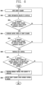
- FIG. 6 an exemplary embodiment of the robot cleaner and the controlling method thereof will be described.
- the driving unit 130 may move the robot cleaner 100 (S601).
- the sensing unit 140 may sense information related to an obstacle (S602).
- the controller 180 may determine whether the distance between the robot cleaner 100 and the obstacle is within the second reference distance by using the sensed information (S603).
- controller 180 may control the driving unit 130 to decrease a moving speed of the robot cleaner 100 (S604).
- the controller 180 may determine whether the distance between the robot cleaner 100 and the obstacle is within the third reference distance by using the sensed information (S605).
- the controller 180 may perform stop control to stop the robot cleaner 100 (S606).
- the controller 180 may determine whether the distance between the robot cleaner 100 and the obstacle is equal to or smaller than the first reference distance (S607).
- the controller 180 performs reverse control with respect to the obstacle (S608).
- the controller 180 may control the driving unit 130 such that the robot cleaner 100 is rotated at a predetermined angle (S609).
- the controller 180 may control the driving unit 130 such that the robot cleaner 100 is rotated at the predetermined angle (S609).
- the controller 180 does not perform the reverse control with respect to the obstacle but may control the driving unit 130 to change the traveling direction of the robot cleaner 100 with respect to the obstacle.
- FIG. 7 an exemplary embodiment of the robot cleaner and the controlling method thereof will be described.
- the driving unit 130 may move the robot cleaner 100 (S701).
- the sensing unit 140 may sense information related to an obstacle (S702).
- the controller 180 may determine whether the distance between the robot cleaner 100 and the obstacle is equal to or smaller than the first reference distance (S703).
- the controller 180 performs reverse control with respect to the obstacle (S704).
- the controller 180 may determine whether the reverse maintenance time has exceeded a predetermined limited time while the reverse control is being performed (S705).
- the predetermined limited time may be set by a user input.
- the controller 180 may control the driving unit to prevent collision between the robot cleaner 100 and the obstacle (S706).
- the controller 180 may determine that the reverse control is ended. Therefore, in order to stop the reverse control of the robot cleaner 100, the controller 180 may control the driving unit 130 to again stop the robot cleaner 100.
- the controller 180 may control the driving unit 130 to rotate the main body of the robot cleaner 100 by a predetermined angle, so as to prevent collision between the robot cleaner 100 and the obstacle.
- the controller 180 may control the driving unit 130 to prevent collision between the robot cleaner 100 and the obstacle by maintaining the distance of the robot cleaner 100 from the outer surface of the obstacle.
- the robot cleaner can effectively perform an avoidance operation with respect to an obstacle, thereby preventing collision of the robot cleaner with the obstacle.
Claims (9)
- Roboterreiniger (100), der Folgendes umfasst:einen Hauptkörper,eine Antriebseinheit (130), die konfiguriert ist, den Hauptkörper zu bewegen;eine Erfassungseinheit (140), die konfiguriert ist, Informationen bezüglich eines Hindernisses (300) zu erfassen; undeine Steuereinheit (180), die konfiguriert ist, die Antriebseinheit (130) zu steuern, um eine Kollision des Hauptkörpers mit dem Hindernis zu verhindern,dadurch gekennzeichnet, dassdie Steuereinheit (180) konfiguriert ist, auf der Basis eines Abstands zwischen dem Hauptkörper und dem Hindernis, nachdem die Informationen bezüglich des Hindernisses erfasst worden sind, einen Stopp-Vorgang auszuführen, wobei dann, wenn der Abstand zwischen dem Hauptkörper und dem Hindernis (300) auf einen zweiten Referenzabstand oder weniger abgenommen hat, die Steuereinheit (180) die Antriebseinheit (130) steuert, den Hauptkörper zu stoppen;wobei die Steuereinheit (180) Informationen bezüglich des zweiten Referenzabstands unter Verwendung von Informationen, die sich auf einen Bremsweg des Hauptkörpers beziehen, festlegt; unddie Steuereinheit (180) konfiguriert ist, die Antriebseinheit (130) auf der Basis des Abstands zwischen dem Hauptkörper und dem Hindernis (300), nachdem der Stopp-Vorgang beendet worden ist, so zu steuern, dass der Hauptkörper in Bezug auf das Hindernis (300) rückwärts fährt, um die Kollision des Hauptkörpers mit dem Hindernis (300) zu verhindern, wobei dann, wenn der Abstand von einem Drehzentrum (400) des Hauptkörpers zu dem Hindernis (300) gleich einem ersten Referenzabstand ist oder kleiner als dieser ist, die Steuereinheit (180) die Antriebseinheit (130) steuert, den Hauptkörper in Bezug auf das Hindernis (300) rückwärts fahren zu lassen,wobei der erste Referenzabstand einem Radius (r) einer Drehung des Roboterreinigers (100) entspricht.
- Roboterreiniger nach einem der Ansprüche 1, wobei dann, wenn der Hauptkörper rückwärts fährt, die Steuereinheit (180) die Antriebseinheit (130) so steuert, dass eine vordere Oberfläche des Hauptkörpers von dem Hindernis (300) durch einen festgelegten Abstand oder weniger beabstandet ist.
- Roboterreiniger nach Anspruch 2, wobei der festgelegte Abstand dem Radius (r) der Drehung entspricht.
- Roboterreiniger nach einem der Ansprüche 1 bis 3, wobei dann, wenn der Hauptkörper rückwärts fährt, die Steuereinheit (180) eine Zeitspanne berechnet, für die das Rückwärtsfahren des Hauptkörpers beibehalten wird, und
wobei dann, wenn die berechnete Zeit eine festgelegte begrenzte Zeitspanne überschreitet, die Steuereinheit (180) die Antriebseinheit (130) steuert, den Hauptkörper zu stoppen. - Roboterreiniger nach einem der Ansprüche 1 bis 4, wobei dann, wenn der Abstand zwischen dem Hauptkörper und dem Hindernis auf einen dritten Referenzabstand oder weniger abgenommen hat, die Steuereinheit (180) die Antriebseinheit (130) steuert, eine Geschwindigkeit des Roboterreinigers (100) zu verringern.
- Roboterreiniger nach Anspruch 5, wobei die Steuereinheit (180) Informationen bezüglich der Größe des Hindernisses (300) durch Verwenden der erfassten Informationen detektiert und Informationen, die sich auf den dritten Referenzabstand beziehen, auf der Basis der detektieren Informationen festlegt.
- Roboterreiniger nach Anspruch 6, wobei die Erfassungseinheit (130) einen Signalübertragungsabschnitt zum Emittieren einer festgelegten Welle zu dem Hindernis (300) und einen Signalaufnahmeabschnitt zum Empfangen der Welle, die von dem Hindernis (300) reflektiert wird, umfasst, und
wobei die Steuereinheit (180) die Informationen bezüglich der Größe des Hindernisses (300) durch Vergleichen der emittierten Welle mit der empfangenen Welle detektiert. - Roboterreiniger nach einem der Ansprüche 1 bis 7, wobei dann, wenn der Hauptkörper, nachdem er gestoppt wurde, rückwärts fährt, die Steuereinheit (180) die Antriebseinheit (130) steuert, den Hauptkörper bis zu einem Punkt rückwärts fahren zu lassen, an dem das Stoppen des Hauptkörpers gestartet worden ist.
- Roboterreiniger nach einem der Ansprüche 1 bis 8, wobei die Steuereinheit (180) die Antriebseinheit (130) steuert, einen Betrieb zum Verhindern der Kollision des Hauptkörpers mit dem Hindernis (300) durch Drehen des Hauptkörpers um einen festgelegten Winkel (a) durchzuführen, nachdem das Rückwärtsfahren des Hauptkörpers beendet worden ist.
Applications Claiming Priority (1)
| Application Number | Priority Date | Filing Date | Title |
|---|---|---|---|
| KR1020150060760A KR101649665B1 (ko) | 2015-04-29 | 2015-04-29 | 이동 로봇 및 그 제어방법 |
Publications (3)
| Publication Number | Publication Date |
|---|---|
| EP3087894A1 EP3087894A1 (de) | 2016-11-02 |
| EP3087894B1 EP3087894B1 (de) | 2020-09-02 |
| EP3087894B2 true EP3087894B2 (de) | 2023-10-18 |
Family
ID=55456698
Family Applications (1)
| Application Number | Title | Priority Date | Filing Date |
|---|---|---|---|
| EP16158683.9A Active EP3087894B2 (de) | 2015-04-29 | 2016-03-04 | Beweglicher roboter und steuerungsverfahren dafür |
Country Status (4)
| Country | Link |
|---|---|
| US (1) | US9785148B2 (de) |
| EP (1) | EP3087894B2 (de) |
| KR (1) | KR101649665B1 (de) |
| CN (1) | CN106073630B (de) |
Families Citing this family (34)
| Publication number | Priority date | Publication date | Assignee | Title |
|---|---|---|---|---|
| US11835343B1 (en) | 2004-08-06 | 2023-12-05 | AI Incorporated | Method for constructing a map while performing work |
| US9915527B2 (en) * | 2014-11-17 | 2018-03-13 | The Boeing Company | Detachable protective coverings and protection methods |
| KR102023966B1 (ko) * | 2015-02-10 | 2019-09-23 | 에브리봇 주식회사 | 로봇 청소기 및 그의 제어 방법 |
| US9919425B2 (en) * | 2015-07-01 | 2018-03-20 | Irobot Corporation | Robot navigational sensor system |
| WO2017196084A1 (ko) * | 2016-05-10 | 2017-11-16 | 엘지전자 주식회사 | 이동 로봇 및 그 제어방법 |
| KR101721386B1 (ko) * | 2016-12-07 | 2017-03-30 | 송수한 | 이동형 자동급식 장치, 반려동물 케어 로봇, 이를 포함하는 반려동물 케어 시스템 및 이를 제어하는 방법 |
| CN107193282B (zh) * | 2017-06-16 | 2020-07-14 | 哈工大机器人集团北京军立方科技有限公司 | 一种智能安防机器人及智能安防系统 |
| CN109421055A (zh) * | 2017-08-25 | 2019-03-05 | 科沃斯机器人股份有限公司 | 自移动机器人 |
| JP7107658B2 (ja) * | 2017-10-11 | 2022-07-27 | 日立グローバルライフソリューションズ株式会社 | 自律走行型掃除機及び自律走行型掃除機システム並びに移動体 |
| US10612929B2 (en) | 2017-10-17 | 2020-04-07 | AI Incorporated | Discovering and plotting the boundary of an enclosure |
| US11274929B1 (en) * | 2017-10-17 | 2022-03-15 | AI Incorporated | Method for constructing a map while performing work |
| WO2019083291A1 (ko) * | 2017-10-25 | 2019-05-02 | 엘지전자 주식회사 | 장애물을 학습하는 인공지능 이동 로봇 및 그 제어방법 |
| CN109901571A (zh) * | 2017-12-10 | 2019-06-18 | 湘潭宏远电子科技有限公司 | 一种机器人驱动模式转换装置 |
| DE102018200726A1 (de) * | 2018-01-17 | 2019-07-18 | BSH Hausgeräte GmbH | Reinigungsroboter und Verfahren zur Steuerung eines Reinigungsroboters |
| US11525921B2 (en) | 2018-04-03 | 2022-12-13 | Sharkninja Operating Llc | Time of flight sensor arrangement for robot navigation and methods of localization using same |
| USD872402S1 (en) * | 2018-04-23 | 2020-01-07 | Eozy International GmbH | Window cleaning robot |
| KR102067600B1 (ko) * | 2018-05-16 | 2020-01-17 | 엘지전자 주식회사 | 청소기 및 그 제어방법 |
| CN109077674A (zh) * | 2018-06-28 | 2018-12-25 | 芜湖泰领信息科技有限公司 | 扫地机的自动避障方法及智能扫地机 |
| WO2020000320A1 (zh) * | 2018-06-28 | 2020-01-02 | 广州艾若博机器人科技有限公司 | 基于光流传感器的测速方法、打滑检测方法、可移动电子设备、路径纠正方法及装置 |
| JP2021170149A (ja) * | 2018-07-09 | 2021-10-28 | ソニーグループ株式会社 | 制御装置、制御方法、およびプログラム |
| CN109085834B (zh) * | 2018-08-27 | 2019-09-03 | 珠海市一微半导体有限公司 | 机器人确定参考边的方法和机器人筛选参考墙边的方法 |
| CN109464075A (zh) * | 2018-12-07 | 2019-03-15 | 江苏美的清洁电器股份有限公司 | 扫地机器人的清扫控制方法及其装置和扫地机器人 |
| CN111466833A (zh) * | 2019-01-24 | 2020-07-31 | 燕成祥 | 清洁机器人的全浮动式接触变向装置 |
| KR20200103900A (ko) * | 2019-02-13 | 2020-09-03 | 삼성전자주식회사 | 청소 로봇 및 그 제어 방법 |
| CN109848995B (zh) * | 2019-03-14 | 2021-04-27 | 南京航空航天大学 | 一种工业机器人碰撞反应方法 |
| KR20210015122A (ko) * | 2019-07-31 | 2021-02-10 | 엘지전자 주식회사 | 인공지능 로봇청소기 및 그를 포함하는 로봇 시스템 |
| KR102309303B1 (ko) * | 2019-10-07 | 2021-10-06 | 엘지전자 주식회사 | 로봇 청소기 및 그 제어 방법 |
| KR20210067432A (ko) * | 2019-11-29 | 2021-06-08 | 엘지전자 주식회사 | 로봇의 비상 정지의 수행 |
| CN110888443A (zh) * | 2019-12-04 | 2020-03-17 | 上海大学 | 一种移动机器人旋转避障方法及系统 |
| US11717120B2 (en) | 2019-12-09 | 2023-08-08 | Sharkninja Operating Llc | Robotic cleaner |
| CN111067438A (zh) * | 2019-12-24 | 2020-04-28 | 江苏美的清洁电器股份有限公司 | 清洁机器人的控制方法、装置、清洁机器人及存储介质 |
| CN111067431B (zh) * | 2019-12-31 | 2023-08-15 | 佛山市云米电器科技有限公司 | 一种扫地机及其检测控制清扫的方法 |
| KR20220056643A (ko) * | 2020-10-28 | 2022-05-06 | 삼성전자주식회사 | 로봇 청소기 및 그의 주행 방법 |
| JP2022100650A (ja) * | 2020-12-24 | 2022-07-06 | トヨタ自動車株式会社 | 荷物搬送システム、荷物搬送方法および荷物搬送プログラム |
Citations (9)
| Publication number | Priority date | Publication date | Assignee | Title |
|---|---|---|---|---|
| DE69312726T2 (de) † | 1992-10-07 | 1998-03-19 | I N C A | Bewegungssteuerungsverfahren für eine autonome in beliebige richtungen fahrende elektrische maschine und dafür geeignete elektrische maschine |
| US5935179A (en) † | 1996-04-30 | 1999-08-10 | Aktiebolaget Electrolux | System and device for a self orienting device |
| US5942869A (en) † | 1997-02-13 | 1999-08-24 | Honda Giken Kogyo Kabushiki Kaisha | Mobile robot control device |
| US20050165508A1 (en) † | 2002-10-01 | 2005-07-28 | Fujitsu Limited | Robot |
| DE10357636B4 (de) † | 2003-12-10 | 2013-05-08 | Vorwerk & Co. Interholding Gmbh | Selbsttätig verfahrbares Bodenstaub-Aufsammelgerät |
| EP2595024A1 (de) † | 2010-07-13 | 2013-05-22 | Murata Machinery, Ltd. | Autonom beweglicher körper |
| EP2764813A2 (de) † | 2013-02-08 | 2014-08-13 | Egenpower Inc. | Mobile Roboterwischmaschine |
| US8855914B1 (en) † | 2012-08-31 | 2014-10-07 | Neato Robotics, Inc. | Method and apparatus for traversing corners of a floored area with a robotic surface treatment apparatus |
| EP2842472A1 (de) † | 2013-07-29 | 2015-03-04 | Samsung Electronics Co., Ltd | Reinigungsroboter und Steuerungsverfahren dafür |
Family Cites Families (20)
| Publication number | Priority date | Publication date | Assignee | Title |
|---|---|---|---|---|
| JPH0947413A (ja) * | 1995-08-08 | 1997-02-18 | Minolta Co Ltd | 清掃ロボット |
| US6594844B2 (en) * | 2000-01-24 | 2003-07-22 | Irobot Corporation | Robot obstacle detection system |
| US6481515B1 (en) | 2000-05-30 | 2002-11-19 | The Procter & Gamble Company | Autonomous mobile surface treating apparatus |
| AU2003256435A1 (en) * | 2002-08-16 | 2004-03-03 | Evolution Robotics, Inc. | Systems and methods for the automated sensing of motion in a mobile robot using visual data |
| KR101240732B1 (ko) * | 2005-02-18 | 2013-03-07 | 아이로보트 코퍼레이션 | 습식 및 건식 청소를 위한 자동 표면 청소 로봇 |
| ATE524784T1 (de) * | 2005-09-30 | 2011-09-15 | Irobot Corp | Begleitroboter für persönliche interaktion |
| JP2008198071A (ja) * | 2007-02-15 | 2008-08-28 | Funai Electric Co Ltd | 自走式装置 |
| EP2995235B1 (de) * | 2007-05-09 | 2021-08-11 | iRobot Corporation | Kompakter roboter mit autonomer reichweite |
| US20090048727A1 (en) | 2007-08-17 | 2009-02-19 | Samsung Electronics Co., Ltd. | Robot cleaner and control method and medium of the same |
| JP4910972B2 (ja) * | 2007-10-11 | 2012-04-04 | パナソニック株式会社 | 自走式装置およびプログラム |
| CN102666032B (zh) * | 2009-10-30 | 2015-01-07 | 悠进机器人股份公司 | 用于移动机器人的滑动检测装置和方法 |
| KR101406186B1 (ko) * | 2009-11-18 | 2014-06-13 | 삼성전자주식회사 | 로봇청소기의 제어방법 |
| JP5062310B2 (ja) * | 2010-08-26 | 2012-10-31 | 村田機械株式会社 | 走行車 |
| CN103534659B (zh) * | 2010-12-30 | 2017-04-05 | 美国iRobot公司 | 覆盖机器人导航 |
| KR101271315B1 (ko) * | 2011-03-28 | 2013-06-04 | 고려대학교 산학협력단 | 이동 로봇의 장애물 회피 시스템 |
| CN104245244B (zh) * | 2012-09-21 | 2016-01-20 | 艾罗伯特公司 | 移动机器人上的接近度感测 |
| KR102020215B1 (ko) * | 2013-03-23 | 2019-09-10 | 삼성전자주식회사 | 로봇 청소기 및 로봇 청소기의 제어방법 |
| CN103356131B (zh) * | 2013-07-24 | 2016-01-13 | 莱克电气股份有限公司 | 用于机器人吸尘器的脱困处理方法 |
| JP2017503267A (ja) * | 2013-12-18 | 2017-01-26 | アイロボット コーポレイション | 自律移動ロボット |
| CN108814422B (zh) * | 2014-01-10 | 2022-04-01 | 艾罗伯特公司 | 自主移动机器人 |
-
2015
- 2015-04-29 KR KR1020150060760A patent/KR101649665B1/ko active IP Right Grant
-
2016
- 2016-01-07 US US14/990,618 patent/US9785148B2/en active Active
- 2016-03-04 EP EP16158683.9A patent/EP3087894B2/de active Active
- 2016-03-04 CN CN201610121615.9A patent/CN106073630B/zh active Active
Patent Citations (9)
| Publication number | Priority date | Publication date | Assignee | Title |
|---|---|---|---|---|
| DE69312726T2 (de) † | 1992-10-07 | 1998-03-19 | I N C A | Bewegungssteuerungsverfahren für eine autonome in beliebige richtungen fahrende elektrische maschine und dafür geeignete elektrische maschine |
| US5935179A (en) † | 1996-04-30 | 1999-08-10 | Aktiebolaget Electrolux | System and device for a self orienting device |
| US5942869A (en) † | 1997-02-13 | 1999-08-24 | Honda Giken Kogyo Kabushiki Kaisha | Mobile robot control device |
| US20050165508A1 (en) † | 2002-10-01 | 2005-07-28 | Fujitsu Limited | Robot |
| DE10357636B4 (de) † | 2003-12-10 | 2013-05-08 | Vorwerk & Co. Interholding Gmbh | Selbsttätig verfahrbares Bodenstaub-Aufsammelgerät |
| EP2595024A1 (de) † | 2010-07-13 | 2013-05-22 | Murata Machinery, Ltd. | Autonom beweglicher körper |
| US8855914B1 (en) † | 2012-08-31 | 2014-10-07 | Neato Robotics, Inc. | Method and apparatus for traversing corners of a floored area with a robotic surface treatment apparatus |
| EP2764813A2 (de) † | 2013-02-08 | 2014-08-13 | Egenpower Inc. | Mobile Roboterwischmaschine |
| EP2842472A1 (de) † | 2013-07-29 | 2015-03-04 | Samsung Electronics Co., Ltd | Reinigungsroboter und Steuerungsverfahren dafür |
Also Published As
| Publication number | Publication date |
|---|---|
| CN106073630A (zh) | 2016-11-09 |
| US9785148B2 (en) | 2017-10-10 |
| CN106073630B (zh) | 2019-02-19 |
| EP3087894B1 (de) | 2020-09-02 |
| KR101649665B1 (ko) | 2016-08-30 |
| US20160320777A1 (en) | 2016-11-03 |
| EP3087894A1 (de) | 2016-11-02 |
Similar Documents
| Publication | Publication Date | Title |
|---|---|---|
| EP3087894B2 (de) | Beweglicher roboter und steuerungsverfahren dafür | |
| AU2016299576B2 (en) | Mobile robot and control method thereof | |
| US10238258B2 (en) | Robot cleaner and method for controlling the same | |
| EP3599962B1 (de) | Reiniger und verfahren zur steuerung davon | |
| EP3258825B1 (de) | Roboterreiniger, fernsteuerungssystem damit und steuerungsverfahren dafür | |
| AU2017402126B2 (en) | Vacuum cleaner and control method thereof | |
| EP3533369B1 (de) | Staubsauger und steuerungsverfahren dafür | |
| US10085608B2 (en) | Robot cleaner | |
| US8800101B2 (en) | Robot cleaner and self testing method of the same | |
| US20130030750A1 (en) | Robot cleaner and self testing method of the same | |
| KR101917701B1 (ko) | 청소기 및 그 제어방법 | |
| EP3797665A1 (de) | Staubsauger und verfahren zur steuerung davon | |
| KR20140011216A (ko) | 로봇 청소기 및 이의 제어 방법 | |
| KR101938668B1 (ko) | 청소기 및 그 제어방법 | |
| KR102122237B1 (ko) | 청소기 및 그 제어방법 | |
| CN110545967A (zh) | 移动机器人及其控制方法 |
Legal Events
| Date | Code | Title | Description |
|---|---|---|---|
| PUAI | Public reference made under article 153(3) epc to a published international application that has entered the european phase |
Free format text: ORIGINAL CODE: 0009012 |
|
| AK | Designated contracting states |
Kind code of ref document: A1 Designated state(s): AL AT BE BG CH CY CZ DE DK EE ES FI FR GB GR HR HU IE IS IT LI LT LU LV MC MK MT NL NO PL PT RO RS SE SI SK SM TR |
|
| AX | Request for extension of the european patent |
Extension state: BA ME |
|
| STAA | Information on the status of an ep patent application or granted ep patent |
Free format text: STATUS: REQUEST FOR EXAMINATION WAS MADE |
|
| 17P | Request for examination filed |
Effective date: 20170421 |
|
| RBV | Designated contracting states (corrected) |
Designated state(s): AL AT BE BG CH CY CZ DE DK EE ES FI FR GB GR HR HU IE IS IT LI LT LU LV MC MK MT NL NO PL PT RO RS SE SI SK SM TR |
|
| GRAP | Despatch of communication of intention to grant a patent |
Free format text: ORIGINAL CODE: EPIDOSNIGR1 |
|
| STAA | Information on the status of an ep patent application or granted ep patent |
Free format text: STATUS: GRANT OF PATENT IS INTENDED |
|
| INTG | Intention to grant announced |
Effective date: 20200402 |
|
| RIN1 | Information on inventor provided before grant (corrected) |
Inventor name: YUN, HYUNGTAE |
|
| GRAS | Grant fee paid |
Free format text: ORIGINAL CODE: EPIDOSNIGR3 |
|
| GRAA | (expected) grant |
Free format text: ORIGINAL CODE: 0009210 |
|
| STAA | Information on the status of an ep patent application or granted ep patent |
Free format text: STATUS: THE PATENT HAS BEEN GRANTED |
|
| AK | Designated contracting states |
Kind code of ref document: B1 Designated state(s): AL AT BE BG CH CY CZ DE DK EE ES FI FR GB GR HR HU IE IS IT LI LT LU LV MC MK MT NL NO PL PT RO RS SE SI SK SM TR |
|
| REG | Reference to a national code |
Ref country code: GB Ref legal event code: FG4D |
|
| REG | Reference to a national code |
Ref country code: AT Ref legal event code: REF Ref document number: 1307819 Country of ref document: AT Kind code of ref document: T Effective date: 20200915 Ref country code: CH Ref legal event code: EP |
|
| REG | Reference to a national code |
Ref country code: DE Ref legal event code: R096 Ref document number: 602016043045 Country of ref document: DE |
|
| REG | Reference to a national code |
Ref country code: IE Ref legal event code: FG4D |
|
| REG | Reference to a national code |
Ref country code: LT Ref legal event code: MG4D |
|
| PG25 | Lapsed in a contracting state [announced via postgrant information from national office to epo] |
Ref country code: BG Free format text: LAPSE BECAUSE OF FAILURE TO SUBMIT A TRANSLATION OF THE DESCRIPTION OR TO PAY THE FEE WITHIN THE PRESCRIBED TIME-LIMIT Effective date: 20201202 Ref country code: NO Free format text: LAPSE BECAUSE OF FAILURE TO SUBMIT A TRANSLATION OF THE DESCRIPTION OR TO PAY THE FEE WITHIN THE PRESCRIBED TIME-LIMIT Effective date: 20201202 Ref country code: GR Free format text: LAPSE BECAUSE OF FAILURE TO SUBMIT A TRANSLATION OF THE DESCRIPTION OR TO PAY THE FEE WITHIN THE PRESCRIBED TIME-LIMIT Effective date: 20201203 Ref country code: FI Free format text: LAPSE BECAUSE OF FAILURE TO SUBMIT A TRANSLATION OF THE DESCRIPTION OR TO PAY THE FEE WITHIN THE PRESCRIBED TIME-LIMIT Effective date: 20200902 Ref country code: LT Free format text: LAPSE BECAUSE OF FAILURE TO SUBMIT A TRANSLATION OF THE DESCRIPTION OR TO PAY THE FEE WITHIN THE PRESCRIBED TIME-LIMIT Effective date: 20200902 Ref country code: SE Free format text: LAPSE BECAUSE OF FAILURE TO SUBMIT A TRANSLATION OF THE DESCRIPTION OR TO PAY THE FEE WITHIN THE PRESCRIBED TIME-LIMIT Effective date: 20200902 Ref country code: HR Free format text: LAPSE BECAUSE OF FAILURE TO SUBMIT A TRANSLATION OF THE DESCRIPTION OR TO PAY THE FEE WITHIN THE PRESCRIBED TIME-LIMIT Effective date: 20200902 |
|
| REG | Reference to a national code |
Ref country code: NL Ref legal event code: MP Effective date: 20200902 |
|
| REG | Reference to a national code |
Ref country code: AT Ref legal event code: MK05 Ref document number: 1307819 Country of ref document: AT Kind code of ref document: T Effective date: 20200902 |
|
| PG25 | Lapsed in a contracting state [announced via postgrant information from national office to epo] |
Ref country code: LV Free format text: LAPSE BECAUSE OF FAILURE TO SUBMIT A TRANSLATION OF THE DESCRIPTION OR TO PAY THE FEE WITHIN THE PRESCRIBED TIME-LIMIT Effective date: 20200902 Ref country code: PL Free format text: LAPSE BECAUSE OF FAILURE TO SUBMIT A TRANSLATION OF THE DESCRIPTION OR TO PAY THE FEE WITHIN THE PRESCRIBED TIME-LIMIT Effective date: 20200902 Ref country code: RS Free format text: LAPSE BECAUSE OF FAILURE TO SUBMIT A TRANSLATION OF THE DESCRIPTION OR TO PAY THE FEE WITHIN THE PRESCRIBED TIME-LIMIT Effective date: 20200902 |
|
| PG25 | Lapsed in a contracting state [announced via postgrant information from national office to epo] |
Ref country code: CZ Free format text: LAPSE BECAUSE OF FAILURE TO SUBMIT A TRANSLATION OF THE DESCRIPTION OR TO PAY THE FEE WITHIN THE PRESCRIBED TIME-LIMIT Effective date: 20200902 Ref country code: NL Free format text: LAPSE BECAUSE OF FAILURE TO SUBMIT A TRANSLATION OF THE DESCRIPTION OR TO PAY THE FEE WITHIN THE PRESCRIBED TIME-LIMIT Effective date: 20200902 Ref country code: SM Free format text: LAPSE BECAUSE OF FAILURE TO SUBMIT A TRANSLATION OF THE DESCRIPTION OR TO PAY THE FEE WITHIN THE PRESCRIBED TIME-LIMIT Effective date: 20200902 Ref country code: PT Free format text: LAPSE BECAUSE OF FAILURE TO SUBMIT A TRANSLATION OF THE DESCRIPTION OR TO PAY THE FEE WITHIN THE PRESCRIBED TIME-LIMIT Effective date: 20210104 Ref country code: RO Free format text: LAPSE BECAUSE OF FAILURE TO SUBMIT A TRANSLATION OF THE DESCRIPTION OR TO PAY THE FEE WITHIN THE PRESCRIBED TIME-LIMIT Effective date: 20200902 Ref country code: EE Free format text: LAPSE BECAUSE OF FAILURE TO SUBMIT A TRANSLATION OF THE DESCRIPTION OR TO PAY THE FEE WITHIN THE PRESCRIBED TIME-LIMIT Effective date: 20200902 |
|
| REG | Reference to a national code |
Ref country code: DE Ref legal event code: R026 Ref document number: 602016043045 Country of ref document: DE |
|
| PG25 | Lapsed in a contracting state [announced via postgrant information from national office to epo] |
Ref country code: IS Free format text: LAPSE BECAUSE OF FAILURE TO SUBMIT A TRANSLATION OF THE DESCRIPTION OR TO PAY THE FEE WITHIN THE PRESCRIBED TIME-LIMIT Effective date: 20210102 Ref country code: ES Free format text: LAPSE BECAUSE OF FAILURE TO SUBMIT A TRANSLATION OF THE DESCRIPTION OR TO PAY THE FEE WITHIN THE PRESCRIBED TIME-LIMIT Effective date: 20200902 Ref country code: AT Free format text: LAPSE BECAUSE OF FAILURE TO SUBMIT A TRANSLATION OF THE DESCRIPTION OR TO PAY THE FEE WITHIN THE PRESCRIBED TIME-LIMIT Effective date: 20200902 Ref country code: AL Free format text: LAPSE BECAUSE OF FAILURE TO SUBMIT A TRANSLATION OF THE DESCRIPTION OR TO PAY THE FEE WITHIN THE PRESCRIBED TIME-LIMIT Effective date: 20200902 |
|
| PLBI | Opposition filed |
Free format text: ORIGINAL CODE: 0009260 |
|
| PLAX | Notice of opposition and request to file observation + time limit sent |
Free format text: ORIGINAL CODE: EPIDOSNOBS2 |
|
| PG25 | Lapsed in a contracting state [announced via postgrant information from national office to epo] |
Ref country code: SK Free format text: LAPSE BECAUSE OF FAILURE TO SUBMIT A TRANSLATION OF THE DESCRIPTION OR TO PAY THE FEE WITHIN THE PRESCRIBED TIME-LIMIT Effective date: 20200902 |
|
| 26 | Opposition filed |
Opponent name: VORWERK & CO. INTERHOLDING GMBH Effective date: 20210528 |
|
| PG25 | Lapsed in a contracting state [announced via postgrant information from national office to epo] |
Ref country code: SI Free format text: LAPSE BECAUSE OF FAILURE TO SUBMIT A TRANSLATION OF THE DESCRIPTION OR TO PAY THE FEE WITHIN THE PRESCRIBED TIME-LIMIT Effective date: 20200902 Ref country code: DK Free format text: LAPSE BECAUSE OF FAILURE TO SUBMIT A TRANSLATION OF THE DESCRIPTION OR TO PAY THE FEE WITHIN THE PRESCRIBED TIME-LIMIT Effective date: 20200902 |
|
| PG25 | Lapsed in a contracting state [announced via postgrant information from national office to epo] |
Ref country code: IT Free format text: LAPSE BECAUSE OF FAILURE TO SUBMIT A TRANSLATION OF THE DESCRIPTION OR TO PAY THE FEE WITHIN THE PRESCRIBED TIME-LIMIT Effective date: 20200902 Ref country code: MC Free format text: LAPSE BECAUSE OF FAILURE TO SUBMIT A TRANSLATION OF THE DESCRIPTION OR TO PAY THE FEE WITHIN THE PRESCRIBED TIME-LIMIT Effective date: 20200902 |
|
| PLBB | Reply of patent proprietor to notice(s) of opposition received |
Free format text: ORIGINAL CODE: EPIDOSNOBS3 |
|
| REG | Reference to a national code |
Ref country code: CH Ref legal event code: PL |
|
| REG | Reference to a national code |
Ref country code: BE Ref legal event code: MM Effective date: 20210331 |
|
| PG25 | Lapsed in a contracting state [announced via postgrant information from national office to epo] |
Ref country code: CH Free format text: LAPSE BECAUSE OF NON-PAYMENT OF DUE FEES Effective date: 20210331 Ref country code: LU Free format text: LAPSE BECAUSE OF NON-PAYMENT OF DUE FEES Effective date: 20210304 Ref country code: LI Free format text: LAPSE BECAUSE OF NON-PAYMENT OF DUE FEES Effective date: 20210331 Ref country code: IE Free format text: LAPSE BECAUSE OF NON-PAYMENT OF DUE FEES Effective date: 20210304 |
|
| PG25 | Lapsed in a contracting state [announced via postgrant information from national office to epo] |
Ref country code: BE Free format text: LAPSE BECAUSE OF NON-PAYMENT OF DUE FEES Effective date: 20210331 |
|
| PGFP | Annual fee paid to national office [announced via postgrant information from national office to epo] |
Ref country code: FR Payment date: 20230206 Year of fee payment: 8 |
|
| APBM | Appeal reference recorded |
Free format text: ORIGINAL CODE: EPIDOSNREFNO |
|
| APBP | Date of receipt of notice of appeal recorded |
Free format text: ORIGINAL CODE: EPIDOSNNOA2O |
|
| APAH | Appeal reference modified |
Free format text: ORIGINAL CODE: EPIDOSCREFNO |
|
| PG25 | Lapsed in a contracting state [announced via postgrant information from national office to epo] |
Ref country code: HU Free format text: LAPSE BECAUSE OF FAILURE TO SUBMIT A TRANSLATION OF THE DESCRIPTION OR TO PAY THE FEE WITHIN THE PRESCRIBED TIME-LIMIT; INVALID AB INITIO Effective date: 20160304 |
|
| APBU | Appeal procedure closed |
Free format text: ORIGINAL CODE: EPIDOSNNOA9O |
|
| PG25 | Lapsed in a contracting state [announced via postgrant information from national office to epo] |
Ref country code: CY Free format text: LAPSE BECAUSE OF FAILURE TO SUBMIT A TRANSLATION OF THE DESCRIPTION OR TO PAY THE FEE WITHIN THE PRESCRIBED TIME-LIMIT Effective date: 20200902 |
|
| PUAH | Patent maintained in amended form |
Free format text: ORIGINAL CODE: 0009272 |
|
| STAA | Information on the status of an ep patent application or granted ep patent |
Free format text: STATUS: PATENT MAINTAINED AS AMENDED |
|
| 27A | Patent maintained in amended form |
Effective date: 20231018 |
|
| AK | Designated contracting states |
Kind code of ref document: B2 Designated state(s): AL AT BE BG CH CY CZ DE DK EE ES FI FR GB GR HR HU IE IS IT LI LT LU LV MC MK MT NL NO PL PT RO RS SE SI SK SM TR |
|
| REG | Reference to a national code |
Ref country code: DE Ref legal event code: R102 Ref document number: 602016043045 Country of ref document: DE |
|
| REG | Reference to a national code |
Ref country code: DE Ref legal event code: R082 Ref document number: 602016043045 Country of ref document: DE Representative=s name: TER MEER STEINMEISTER & PARTNER PATENTANWAELTE, DE |
|
| PG25 | Lapsed in a contracting state [announced via postgrant information from national office to epo] |
Ref country code: MK Free format text: LAPSE BECAUSE OF FAILURE TO SUBMIT A TRANSLATION OF THE DESCRIPTION OR TO PAY THE FEE WITHIN THE PRESCRIBED TIME-LIMIT Effective date: 20200902 |
|
| PGFP | Annual fee paid to national office [announced via postgrant information from national office to epo] |
Ref country code: DE Payment date: 20240205 Year of fee payment: 9 Ref country code: GB Payment date: 20240205 Year of fee payment: 9 |