EP3087821B1 - Landwirtschaftlicher erntevorsatz mit multifinger-einzugsanordnung - Google Patents
Landwirtschaftlicher erntevorsatz mit multifinger-einzugsanordnung Download PDFInfo
- Publication number
- EP3087821B1 EP3087821B1 EP16167590.5A EP16167590A EP3087821B1 EP 3087821 B1 EP3087821 B1 EP 3087821B1 EP 16167590 A EP16167590 A EP 16167590A EP 3087821 B1 EP3087821 B1 EP 3087821B1
- Authority
- EP
- European Patent Office
- Prior art keywords
- finger
- hub
- pivoting
- hollow tube
- driving
- Prior art date
- Legal status (The legal status is an assumption and is not a legal conclusion. Google has not performed a legal analysis and makes no representation as to the accuracy of the status listed.)
- Active
Links
Images


Classifications
-
- A—HUMAN NECESSITIES
- A01—AGRICULTURE; FORESTRY; ANIMAL HUSBANDRY; HUNTING; TRAPPING; FISHING
- A01D—HARVESTING; MOWING
- A01D89/00—Pick-ups for loaders, chaff-cutters, balers, field-threshers, or the like, i.e. attachments for picking-up hay or the like field crops
- A01D89/001—Pick-up systems
- A01D89/002—Rotors
-
- A—HUMAN NECESSITIES
- A01—AGRICULTURE; FORESTRY; ANIMAL HUSBANDRY; HUNTING; TRAPPING; FISHING
- A01D—HARVESTING; MOWING
- A01D57/00—Delivering mechanisms for harvesters or mowers
- A01D57/01—Devices for leading crops to the mowing apparatus
- A01D57/02—Devices for leading crops to the mowing apparatus using reels
- A01D57/03—Devices for leading crops to the mowing apparatus using reels with supplementary controlled movement of the crop-engaging members, e.g. of the tines
-
- A—HUMAN NECESSITIES
- A01—AGRICULTURE; FORESTRY; ANIMAL HUSBANDRY; HUNTING; TRAPPING; FISHING
- A01D—HARVESTING; MOWING
- A01D61/00—Elevators or conveyors for binders or combines
- A01D61/008—Elevators or conveyors for binders or combines for longitudinal conveying, especially for combines
-
- A—HUMAN NECESSITIES
- A01—AGRICULTURE; FORESTRY; ANIMAL HUSBANDRY; HUNTING; TRAPPING; FISHING
- A01D—HARVESTING; MOWING
- A01D61/00—Elevators or conveyors for binders or combines
- A01D61/002—Elevators or conveyors for binders or combines transversal conveying devices
Definitions
- the present invention relates to agricultural harvesters, and, more particularly, to header assemblies for agricultural harvesters.
- Combines are used to harvest agricultural crops such as corn, soybeans, wheat and other grain crops. As the combine is driven through crop fields, the combine cuts the crop, separates the desired crop from the undesired waste, stores the crop, and discards the waste.
- a header is mounted to the front of the combine to gather the crop and feed the crop into the combine for processing.
- the crop material is collected by the header and deposited into a feeder housing.
- the crop material is then transported upwardly and into the combine by a feed elevator located within the feeder housing.
- the crop material then passes through a threshing and separating mechanism.
- the threshing and separating mechanism includes a rotor, a threshing concave, a rotor cage, and a separating grate.
- the stalk material that is separated from the grain is commonly referred to as material other than grain (MOG).
- MOG material other than grain
- the grain cleaning system of a typical combine includes a plurality of adjustable cleaning sieves, often referred to as a chaffer sieve and a shoe sieve.
- the sieves are typically reciprocated back and forth in opposite directions along an arcuate path. This motion has the tendency to separate the grain from the MOG.
- a cleaning fan or blower is positioned so as to blow air up through the cleaning sieves. This flow of air tends to blow the MOG, which is typically lighter than grain, rearwardly and out the back of the combine. Grain, which is heavier than MOG, is allowed to drop through the openings in the sieve.
- the clean grain that falls through the cleaning sieves is deposited on a collection panel positioned beneath the cleaning sieves.
- the collection panel is angled so as to permit the grain to flow, under the influence of gravity, into an auger trough positioned along the lowermost edge of the collection panel.
- the auger trough is typically positioned near the forward end of the cleaning sieves and extends along the width of the sieves.
- the grain collected in the auger trough is then moved by an auger towards the side of the combine where it is raised by a grain elevator and deposited into a storage tank or grain tank.
- Other systems also exist that can utilize, for example, a loop conveyor system which eliminates the need for a conventional cross auger.
- an infeed assembly can be included in the header that directs the cut crop into a middle of the header and then utilizes rotating fingers to push the cut crop material toward the feeder housing.
- multiple fingers can be included in the infeed assembly.
- the infeed assembly taught by Olivari includes rake-like members, which can be fingers, on a revolving shaft that sweep and pick up leaves and other debris from a lawn and move them upwards within the housing of the device.
- the fingers extend outwardly from the shaft and the ends pass through apertures formed in a drum.
- the drum is off-center in relation to the shaft of the fingers so that in the revolving of the mechanism the ends of the fingers move back and forth through the apertures in the drum.
- the fingers taught by Olivari are made of a flexible material so that they can bend during operation as the relative position of the shaft to which they are attached changes in relation to the apertures in the drum. This flexibility allows the fingers to operate in the configuration taught by Olivari to push leaves and other light, flimsy materials, but makes them unsuitable for pushing heavier materials that would cause the fingers to bend during contact rather than the material being pushed by the fingers.
- the separator taught by Tetreault includes a drum mounted for rotation about a first horizontal axis that constitutes an outer separator element, and an inner separator element mounted within the drum for rotation about a second horizontal axis which is spaced from and parallel with the first axis.
- the drum has apertures in its outer surface and the inner separator element includes pins which extend through the apertures, so that rotation of the inner and outer separator elements about their respective axes causes the outer end of each pin to reciprocate within the aperture between an inner position where the end of the pin is flush with the outer surface of the drum to an outer position where the end of the pin extends beyond the outer surface of the drum.
- the pins are attached to spindles, with most of the spindles being free to pivot and one of the spindles being fixed against pivoting.
- the spindles are driven by a shaft, with the fixed spindle's pins driving the drum.
- One problem with this arrangement is that the arrangement of the spindles is complicated and each spindle must extend the length of the inner separator element. Further, to keep one of the spindles fixed, bushings are placed in apertures of the drum to hold the fixed spindle's pins in place, which can wear away and allow the previously fixed spindle to pivot.
- U.S. Patent No. 2,529,180 discloses a combine harvester header with an auger tube comprising a rotating finger unit.
- the present invention provides an infeed assembly having a rotatable tube with openings formed therein and a finger unit rotatably held in the tube having at least one pivoting finger extending out of an opening of the tube and a driving finger extending into an opening of the tube to rotate the finger unit by the tube.
- the invention in one form is directed to an agricultural harvester including: a chassis; a threshing and separating mechanism carried by the chassis; a feeder housing carried by the chassis and configured to supply crop material to the threshing and separating mechanism; and a header carried by the chassis in front of the feeder housing.
- the header includes a cutting mechanism configured to cut crop material and an infeed assembly carried behind the cutting mechanism configured to direct the cut crop material toward the feeder housing.
- the infeed assembly includes a driving element configured to rotate; a hollow tube rotationally coupled to the driving element and having a plurality of openings formed therein; and at least one finger unit rotatably held within the hollow tube.
- Each finger unit includes: a finger hub having a circular cross-section and at least one pivoting aperture and at least one driving aperture formed on a circumferential surface of said finger hub; a pivoting finger pivotally held within the at least one pivoting aperture and configured to at least partially extend out of one of the openings of the hollow tube during rotation; and a driving finger fixedly held within the at least one driving aperture and configured to at least partially extend into one of the openings of the hollow tube to rotate the finger unit by the hollow tube.
- An advantage of the present invention is that a conveyance rate of cut crop material toward the feeder housing of an agricultural harvester can be increased.
- finger units can be easily replaced by other identical finger units.
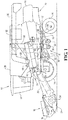
- an agricultural harvester in the form of a combine 10, which generally includes a chassis 12, ground engaging wheels 14 and 16, a header 18, a feeder housing 20, an operator cab 22, a threshing and separating system 24, a cleaning system 26, a grain tank 28, and an unloading auger 30.
- a conventional combine which does not have a rotor
- rotary combine which does not have a rotor
- hybrid combine hybrid combine
- chopper harvester etc.
- Front wheels 14 are larger flotation type wheels, and rear wheels 16 are smaller steerable wheels. Motive force is selectively applied to front wheels 14 through a power plant in the form of a diesel engine 32 and a transmission (not shown).
- combine 10 is shown as including wheels, is also to be understood that combine 10 may include tracks, such as full tracks or half tracks.
- Header 18 is mounted to the front of combine 10 and includes a cutter bar 34 for severing crops from a field during forward motion of combine 10.
- a rotatable reel 36 feeds the crop into header 18, and a double auger 38 feeds the severed crop laterally inwardly from each side toward feeder housing 20. While the rotatable reel 36 is shown as feeding crop material into the header 18, it should be appreciated that the rotatable reel 36 is optional.
- Feeder housing 20 conveys the cut crop to threshing and separating system 24, and is selectively vertically movable using appropriate actuators, such as hydraulic cylinders (not shown).
- Threshing and separating system 24 is of the axial-flow type, and generally includes a rotor 40 at least partially enclosed by and rotatable within a corresponding perforated concave 42.
- the cut crops are threshed and separated by the rotation of rotor 40 within concave 42, and larger elements, such as stalks, leaves and the like are discharged from the rear of combine 10.
- Smaller elements of crop material including grain and non-grain crop material, including particles lighter than grain, such as chaff, dust and straw, are discharged through perforations of concave 42.
- Cleaning system 26 may include an optional pre-cleaning sieve 46, an upper sieve 48 (also known as a chaffer sieve), a lower sieve 50 (also known as a shoe sieve), and a cleaning fan 52. Grain on sieves 46, 48 and 50 is subjected to a cleaning action by fan 52 which provides an airflow through the sieves to remove chaff and other impurities such as dust from the grain by making this material airborne for discharge from straw hood 54 of combine 10.
- Grain pan 44 and pre-cleaning sieve 46 oscillate in a fore-to-aft manner to transport the grain and finer non-grain crop material to the upper surface of upper sieve 48.
- Upper sieve 48 and lower sieve 50 are vertically arranged relative to each other, and likewise oscillate in a fore-to-aft manner to spread the grain across sieves 48, 50, while permitting the passage of cleaned grain by gravity through the openings of sieves 48, 50.
- Clean grain falls to a clean grain auger 56 positioned crosswise below and in front of lower sieve 50.
- Clean grain auger 56 receives clean grain from each sieve 48, 50 and from bottom pan 62 of cleaning system 26.
- Clean grain auger 56 conveys the clean grain laterally to a generally vertically arranged elevator 60, which can also be referred to as a grain elevator, for transport to grain tank 28.
- Tailings from cleaning system 26 fall to a tailings auger on 62. The tailings are transported via tailings auger 64 and return auger 66 to the upstream end of cleaning system 26 for repeated cleaning action.
- a pair of grain tank augers 68 at the bottom of grain tank 28 convey the clean grain laterally within grain tank 28 to unloading auger 30 for discharge from combine 10.
- Residue handling system 70 may include a chopper, counter knives, a windrow door and a residue spreader.
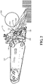
- the header 18 includes an infeed assembly 72 that is held behind the cutter bar 34 (which can also be referred to as a cutting mechanism) and directs cut crop material toward the feeder housing 20.
- the infeed assembly 72 generally includes a driving element 74, shown as a drive shaft, configured to rotate, a hollow tube 76 rotationally coupled to the drive shaft 74 that has openings (shown in Fig. 4 ) formed therein, and one or more finger units 78 rotatably held within the hollow tube 76. Only one finger unit 78 is shown in Figs. 2-5D for ease of illustration and description, but it should be appreciated that multiple finger units 78 can be included in the infeed assembly 72, as shown in Fig. 6 .
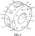
- the finger unit 78 includes a finger hub 80, which is shown in better detail in Fig. 3 , with one or more pivoting apertures 82 (shown in Fig. 3 ) and one or more driving apertures 84 (shown in Fig. 3 ) formed therein, a pivoting finger 86 pivotally held within a pivoting aperture 82, and a driving finger 88 fixedly held within a driving aperture 84.
- the finger hub 80 can include a single driving aperture 84 with seven pivoting apertures 82, but it is contemplated that there can be more than one driving aperture 84 and fewer or more than seven pivoting apertures 82 formed in the finger hub 80.
- Each pivoting aperture 82 can pivotally hold a pivoting finger 86 within and each driving aperture 84 can fixedly hold a driving finger 88 within, the significance of which will be further described further herein.
- the pivoting finger 86 and driving finger 88 can be formed as cylindrically shaped rods, as shown, or other shapes that allow the fingers 86 and 88 to push cut crop material toward the feeder housing 20 as the fingers 86 and 88 are rotated. It is also useful if the fingers 86 and 88 are formed of a rigid material that does not easily bend, such as a hard metal or polymer, so that when the fingers 86 and 88 contact cut crop material they will not be deformed so much that they are unable to move the cut crop material.
- the finger hub 80 can be formed to have a circular cross-section, with a circumference defined about a center C1 of the finger hub 80 and a circumferential surface 90 defining an outer surface of the finger hub 80.
- the pivoting apertures 82 and driving aperture 84 can be formed in the circumferential surface 90 of the finger hub 80 so that fingers 86 and 88 held in the apertures 82 and 84 extend radially outward relative to the center C 1 of the finger hub 80.
- the apertures 82 and 84 can be equally spaced along the circumferential surface 90 of the finger hub 80, as shown, or otherwise formed on the circumferential surface 90.
- the pivoting apertures 82 can be elongated slots, as shown, which have a length that extends along the circumference of the finger hub 80.
- Pin openings 92 can be formed through the finger hub 80 into the pivoting apertures 82, with pivot pins 94 (shown in Fig. 4 ) inserted through the pin openings 92 and openings(not shown) formed in the pivoting fingers 86 to allow the pivoting fingers 86 to pivot about the pivot pins 94 in the pivoting apertures 82.
- the driving aperture 84 can be formed to closely correspond to the driving finger 88 so the driving finger 88 is tightly held within the driving aperture 84 and its ability to pivot or otherwise move is extremely limited.
- Fixation openings 96 can be formed in the finger hub 80 that extend into the driving aperture 84 to allow fixation pins 98 (shown in Fig. 4 ) to be connected to the driving finger 88 and assist in keeping the driving finger 88 fixedly held within the driving aperture 84.
- the finger hub 80 can also be formed to have a central opening 100 that will allow the finger hub 80 to slide over a shaft.
- the infeed assembly 72 is shown in a perspective view to better illustrate its components.
- the drive shaft 74 can drive one auger of the double auger 38 and carry a flighting 101 so that as the drive shaft 74 rotates, the flighting 101 conveys cut crop material toward the infeed assembly 72.
- the driving element 74 is shown as being a drive shaft of an auger, it is contemplated that the driving element 74 can be any type of rotating element.
- the hollow tube 76 is rotationally coupled to the drive shaft 74 such that rotation of the drive shaft 74 causes rotation of the hollow tube 76.
- the hollow tube 76 can be coupled to the drive shaft 74 in an orientation where the drive shaft 74 defines a tube axis of rotation A1 which the hollow tube 76 rotates about, i.e., the hollow tube 76 is concentrically coupled to the drive shaft 74.
- the hollow tube 76 is shown as being directly coupled to the drive shaft 74, but can also be indirectly coupled to the drive shaft 74 if desired.
- the hollow tube 76 has openings 102 formed therein which can extend entirely through an outer surface 104 of the hollow tube 76.
- the openings 102 are formed as elongated slots that extend along a length of the hollow tube 76, but the openings 102 can assume any shape that allows for fingers 86 and 88 of the finger unit 78 to extend into the openings 102.
- the elongated slots 102 can have a width in the direction of the circumference of the hollow tube 76 that is greater than the circumference of the fingers 86 and 88, allowing for relative movement between the hollow tube 76 and the fingers 86 and 88.
- the finger unit 78 can be rotatably held inside the hollow tube 76 by sliding the central opening 100 of the finger hub 80 over a hub shaft 106 held in an axis block 108 connected to the drive shaft 74.
- the hub shaft 106 can define a hub axis of rotation A2 that, due to the position it is held in by the axis block 108, is parallel and offset from the tube axis of rotation A1. This offset allows the position of the fingers 86 and 88 relative to the elongated slots 102 of the hollow tube 76 to shift as the hollow tube 76 and finger unit 78 rotate, which is described further herein.
- the hub shaft 106 can be fixedly held in the axis block 108 so that the hub shaft 106 does not rotate and the finger unit 78 rotates about the hub shaft 106 but is not rotated by the hub shaft 106.
- the hub shaft 106 can be rotatably held anywhere within the hollow tube 76 that allows the driving finger 88 to extend into an opening 102 of the hollow tube 76 and the pivoting fingers 86 to extend out of openings 102.
- the drive shaft 74 is rotated by a rotating element (not shown) in a direction of rotation, signified by arrow 110 and shown as clockwise. Since the hollow tube 76 is rotationally coupled to the drive shaft 74, the hollow tube 76 will also rotate as the drive shaft rotates 74.
- the driving finger 88 of the finger unit 78 is fixedly held in the finger hub 80 and extends into an opening 102 of the hollow tube 76 so that as the hollow tube 76 rotates, a side wall 112 of the opening 102 will be pressed against the driving finger 88 and force the driving finger 88 in the direction of rotation 110.
- pivoting fingers 86 are pivotally connected to the finger hub 80, they will tend to pivot about their respective pivot pins 94 connecting the pivoting fingers 86 to the finger hub 80 in the direction of rotation 110 and gravity. Pivoting movement of the pivoting fingers 86 can be limited by sidewalls 112 of the respective opening 102 that each pivoting finger 86 extends through as well as sidewalls 114 of the pivoting aperture 82 the pivoting finger 86 is held within. This pivoting movement of the pivoting fingers 86 allows for the angle of incidence formed between each pivoting finger 86 and the finger hub 80 to change as the finger unit 78 rotates.
- FIGs. 5A-5D the position of the fingers 86 and 88 relative to the finger hub 80 and changing angle of incidence can be seen.
- the clock position of various fingers when describing Figs. 5A-5D , with it being understood that the clock positions analogize the fingers 86 and 88 to hands on a standard 12 hour clock having 30 degrees between each hour.
- the driving finger 88 is in the 6 o'clock position, with pivoting fingers 86 at various angles relative to the finger hub 80.
- the hollow tube 76 rotates so that the finger unit 78 rotates 90 degrees clockwise, as shown in Fig.
- the driving finger 88 assumes the 9 o'clock position and the angles between the pivoting fingers 86 and the finger hub 80 switch due to the pivoting fingers 86 pivoting so that they stay in their respective opening 102 of the hollow tube 76.
- the driving finger 88 is in the 9 o'clock position, it is transverse to both the tube axis of rotation A1 defined by drive shaft 74 and the hub axis of rotation A2 defined by hub shaft 106.
- one of the pivoting fingers designated as pivoting finger 86B, is also transverse to both the tube axis of rotation A1 and hub axis of rotation A2.
- the finger unit 78 rotates another 90 degrees clockwise, as shown in Fig.
- the driving finger 88 assumes the 12 o'clock position and the pivoting fingers 86 pivot again to different angles relative to the finger hub 80.
- the pivoting fingers 86 congregate near the 6 o'clock position of the finger hub 80.
- the driving finger 88 assumes the 3 o'clock position. In the 3 o'clock position, the driving finger 88 is once again transverse to both the tube axis of rotation A1 and hub axis of rotation A2 and one pivoting finger, designated as 86D, is also transverse both axes of rotation A1 and A2.
- the infeed assembly 72 is shown with two finger units 78 forming paddles 116.
- the hollow tube 76 that the finger units 78 are held within has been omitted from Fig. 6 .
- the paddles 116 can be formed by attaching plates 118 between one finger, with an example finger being designated 120, of a first finger unit, designated 78A, and another finger, designated 122, of a second finger unit, designated 78B.
- Rigid paddles 116 can be formed by connecting two pivoting fingers 86 or two driving fingers 88 of adjacent finger units 78, since the connected fingers will tend to stay in the same plane during rotation, and more flexible paddles can be formed by connecting a pivoting finger 86 to a driving finger 88 of an adjacent finger unit 78.
- the openings 102 of the hollow tube 76 that the fingers 120 and 122 forming the paddles 116 extend through should also be shaped to allow extension of the plates 118 therethrough.
- the fingers 120 and 122 forming part of the paddle 116 are rigid, since the paddle 116 can be configured to push more cut crop material than fingers 120 and 122 would be able to without the connecting plate 118 and the resulting pushback force from the cut crop material could bend a flimsy finger. It should be appreciated that the fingers 120 and 122 forming part of the paddle 116 can be connected by a planar plate 118 formed of sheet metal, as shown, or the plate 118 can be formed of a polymer or other material or be at least partially curved.
Claims (8)
- Landwirtschaftliche Erntemaschine (10) mit:einem Hauptrahmen (12);einem Dresch- und Abscheidesystem (24), das von dem Hauptrahmen (12) getragen wird;einem Förderergehäuse (20), das von dem Hauptrahmen (12) getragen wird und das dazu eingerichtet ist, Erntegut zu dem Dresch- und Abscheidesystem (24) zu fördern; undeinem Vorsatz (18), der von dem Hauptrahmen (12) vor dem Förderergehäuse (20) getragen wird, wobei der Vorsatz (18) ein Schneidwerk (34), das dazu eingerichtet ist, das Erntematerial zu schneiden, und eine Zuführanordnung (72) aufweist, die hinter dem Schneidwerk (34) getragen wird und die dazu eingerichtet ist, das Erntegut in Richtung des Förderergehäuses (20) zu führen, wobei die Zuführanordnung (72) ein Antriebselement (74) aufweist, das dazu eingerichtet ist, sich zu drehen;einem hohlen Rohr (76), das drehbar mit dem Antriebselement (74) verbunden ist und eine Mehrzahl von darin ausgebildeten Öffnungen (102) aufweist;mindestens einer Fingereinheit (78), die drehbar innerhalb des hohlen Rohrs (76) aufgenommen ist und dadurch gekennzeichnet ist, dass jede Fingereinheit (78) aufweist:eine Fingernabe (80) mit einem kreisförmigen Querschnitt und mindestens einer Schwenköffnung (82) und mindestens einer Antriebsöffnung (84), die in einer Umfangsfläche (90) der Fingernabe (80) ausbildet sind;einen Schwenkfinger (86), der schwenkbar in der mindestens einen Schwenköffnung (82) aufgenommen ist und dazu eingerichtet ist, sich während des Drehens zumindest teilweise aus einer der Mehrzahl von Öffnungen (102) des hohlen Rohres (76) hinaus zu erstrecken; undeinen Antriebsfinger (88), der fest in der mindestens einen Antriebsöffnung (84) aufgenommen ist und der dazu eingerichtet ist, sich zumindest teilweise in eine der Mehrzahl von Öffnungen (102) des hohlen Rohrs (76) zu erstrecken, um die Fingereinheit (78) mittels des hohlen Rohrs (76) zu drehen.
- Landwirtschaftliche Erntemaschine (10) nach Anspruch 1, wobei die Zuführanordnung (72) mindestens zwei Fingereinheiten (78), die drehbar innerhalb des hohlen Rohres (76) gehalten sind, und eine Platte (118) aufweist, die einen Schwenkfinger (86) oder einen Antriebsfinger (88) einer ersten Fingereinheit (78a) mit einem Schwenkfinger (86) oder einem Antriebsfinger (88) einer zweiten Fingereinheit (78b) verbindet, um eine Schaufel (116) zu bilden.
- Landwirtschaftliche Erntemaschine (10) nach Anspruch 1, wobei die Fingereinheit (78) eine Nabenwelle (106) aufweist, die in dem hohlen Rohr (76) aufgenommen ist, wobei mindestens eine Fingernabe (80) drehbar auf der Nabenwelle (106) aufgenommen ist.
- Landwirtschaftliche Erntemaschine (10) nach Anspruch 3, wobei das Antriebselement (74) eine Rohrdrehachse (A1) definiert und die Nabenwelle (106) eine Nabendrehachse (A2) definiert, wobei die Nabendrehachse (A2) zu der Rohrdrehachse (A1) versetzt ist.
- Landwirtschaftliche Erntemaschine (10) nach Anspruch 1, wobei mindestens eine der Mehrzahl von Öffnungen (102), die in dem hohlen Rohr (76) ausgebildet ist, ein länglicher Schlitz ist.
- Landwirtschaftliche Erntemaschine (10) nach Anspruch 1, wobei die Fingernabe (80) einen Umfang definiert und die mindestens eine Schwenköffnung (82) eine längliche Öffnung ist, die sich entlang dieses Umfangs auf der Umfangsfläche (90) erstreckt.
- Landwirtschaftliche Erntemaschine (10) nach Anspruch 6, wobei die Fingernabe (80) mindestens eine Bolzenöffnung (92), die durch die mindestens eine Schwenköffnung (82) hindurch ausgebildet ist, und einen Schwenkbolzen (94) aufweist, der schwenkbar mit dem Schwenkfinger (86) verbunden ist und in der mindestens einen Bolzenöffnung (92) angeordnet ist.
- Landwirtschaftliche Erntemaschine (10) nach Anspruch 1, wobei der mindestens eine Schwenkfinger (86) und der mindestens eine Antriebsfinger (88) biegesteif ausgebildet sind.
Applications Claiming Priority (1)
| Application Number | Priority Date | Filing Date | Title |
|---|---|---|---|
| US14/700,701 US9591806B2 (en) | 2015-04-30 | 2015-04-30 | Agricultural header with multiple finger infeed assembly |
Publications (2)
| Publication Number | Publication Date |
|---|---|
| EP3087821A1 EP3087821A1 (de) | 2016-11-02 |
| EP3087821B1 true EP3087821B1 (de) | 2018-01-03 |
Family
ID=55860748
Family Applications (1)
| Application Number | Title | Priority Date | Filing Date |
|---|---|---|---|
| EP16167590.5A Active EP3087821B1 (de) | 2015-04-30 | 2016-04-29 | Landwirtschaftlicher erntevorsatz mit multifinger-einzugsanordnung |
Country Status (3)
| Country | Link |
|---|---|
| US (1) | US9591806B2 (de) |
| EP (1) | EP3087821B1 (de) |
| BR (1) | BR102016009860B1 (de) |
Cited By (2)
| Publication number | Priority date | Publication date | Assignee | Title |
|---|---|---|---|---|
| RU2735253C2 (ru) * | 2016-05-03 | 2020-10-29 | Дир Энд Компани | Барабанный транспортер |
| CN112384438A (zh) * | 2018-06-26 | 2021-02-19 | 卡特彼勒公司 | 用于机器的履带组件 |
Families Citing this family (3)
| Publication number | Priority date | Publication date | Assignee | Title |
|---|---|---|---|---|
| BE1021143B1 (nl) * | 2013-05-06 | 2016-01-18 | Cnh Industrial Belgium Nv | Opraapeenheid voor een oogstmachine met verwijderbare verlengplaten |
| AR114762A1 (es) * | 2018-04-11 | 2020-10-14 | Cnh Ind America Llc | Tornillo sinfín de tubo con púas |
| US11623221B1 (en) | 2022-02-15 | 2023-04-11 | Kurt M. Schie | In-feed roller for a wood chipper and method of making thereof |
Family Cites Families (22)
| Publication number | Priority date | Publication date | Assignee | Title |
|---|---|---|---|---|
| US3126693A (en) * | 1964-03-31 | Flexible grain pickup elements and mounting | ||
| US675418A (en) * | 1899-03-30 | 1901-06-04 | J F Montgomery | Beater and picker for grain-separators. |
| US2529180A (en) * | 1946-08-02 | 1950-11-07 | Deere & Co | Harvesting mechanism |
| US2633231A (en) * | 1950-09-18 | 1953-03-31 | Deere & Co | Rotatable crop feeder with bearings for retracting fingers |
| US2803505A (en) * | 1953-11-03 | 1957-08-20 | Allis Chalmers Mfg Co | Finger bearing retainer for feed cylinder |
| DE1929279U (de) | 1965-10-16 | 1965-12-16 | Josef Bautz G M B H | Einzugtrommel fuer erntemaschinen. |
| DE2001386C3 (de) * | 1970-01-14 | 1974-02-14 | Deere & Company, Moline, Ill. (V.St.A.) | Vorrichtung zum Verteilen und Lockern des aus der Dreschvorrichtung eines Mähdreschers anfallenden Gutes |
| US4085573A (en) * | 1976-04-08 | 1978-04-25 | Preston Marsh | Farm crop pick-up apparatus |
| DE2656053A1 (de) * | 1976-12-10 | 1978-06-15 | Fahr Ag Maschf | Futterschneidmaschine |
| US4297760A (en) | 1978-08-28 | 1981-11-03 | Humbert Olivari | Debris picker and bagger |
| US4217672A (en) | 1978-08-28 | 1980-08-19 | Humbert Olivari | Debris picker and bagger |
| US4484684A (en) | 1982-05-17 | 1984-11-27 | Tetreault Merritt D | Parts separator |
| US4453375A (en) * | 1982-12-13 | 1984-06-12 | Field Robert D | Feed auger attachment |
| US4539801A (en) * | 1984-03-30 | 1985-09-10 | Field Robert D | Resilient feed auger attachment |
| US4574815A (en) * | 1984-08-29 | 1986-03-11 | Deere & Company | Rotor for an axial flow rotary separator |
| DE19920538A1 (de) | 1999-05-05 | 2000-11-09 | Claas Selbstfahr Erntemasch | Erntemaschine |
| DE10042499A1 (de) | 2000-08-30 | 2002-03-14 | Deere & Co | Rotationsförderer mit Fingern |
| US7392646B2 (en) * | 2004-06-16 | 2008-07-01 | Macdon Industries Ltd. | Reversible feed roller with radially extendible fingers |
| US7426819B2 (en) * | 2006-10-06 | 2008-09-23 | Cnh America Llc | Auger finger with resilient elastomeric retainer retractor at breaking point |
| BRPI0903650B1 (pt) * | 2009-09-17 | 2018-02-06 | Agco Do Brasil Máquinas E Equipamentos Agrícolas Ltda. | Dedo retrátil para montagem em um eixo principal de caracol de colheitadeiras de grãos |
| RU2430504C1 (ru) * | 2010-03-09 | 2011-10-10 | Юрий Иванович Попов | Комбинированное устройство для уборки подсолнечника |
| CA2875047C (en) * | 2014-01-30 | 2016-05-24 | Macdon Industries Ltd. | Finger drive for a crop feed roller |
-
2015
- 2015-04-30 US US14/700,701 patent/US9591806B2/en active Active
-
2016
- 2016-04-29 EP EP16167590.5A patent/EP3087821B1/de active Active
- 2016-05-02 BR BR102016009860-2A patent/BR102016009860B1/pt active IP Right Grant
Non-Patent Citations (1)
| Title |
|---|
| None * |
Cited By (3)
| Publication number | Priority date | Publication date | Assignee | Title |
|---|---|---|---|---|
| RU2735253C2 (ru) * | 2016-05-03 | 2020-10-29 | Дир Энд Компани | Барабанный транспортер |
| CN112384438A (zh) * | 2018-06-26 | 2021-02-19 | 卡特彼勒公司 | 用于机器的履带组件 |
| CN112384438B (zh) * | 2018-06-26 | 2023-06-02 | 卡特彼勒公司 | 用于机器的履带组件 |
Also Published As
| Publication number | Publication date |
|---|---|
| BR102016009860B1 (pt) | 2021-07-13 |
| BR102016009860A2 (pt) | 2016-11-01 |
| US20160316628A1 (en) | 2016-11-03 |
| EP3087821A1 (de) | 2016-11-02 |
| US9591806B2 (en) | 2017-03-14 |
Similar Documents
| Publication | Publication Date | Title |
|---|---|---|
| EP3627985B1 (de) | Einstellsystem für fingerartige roste einer landwirtschaftlichen erntemaschine | |
| EP3087821B1 (de) | Landwirtschaftlicher erntevorsatz mit multifinger-einzugsanordnung | |
| US9578806B2 (en) | Agricultural harvester header with retracting paddles for conveying crop material | |
| US11272665B2 (en) | Tined-tube auger | |
| US11259466B2 (en) | Agricultural elevator supplied by multiple cross augers | |
| EP3090621B1 (de) | Mähdrescher mit körnerelevator | |
| EP3087825B1 (de) | Schneckenanordnung für landwirtschaftliche erntemaschine | |
| EP2993968B1 (de) | Häcksler/gebläsanordnung für einen vorsatz einer landwirtschaftlichen erntemaschine | |
| EP3217782B1 (de) | Landwirtschaftliche erntemaschine mit einem gedrehten elevator | |
| EP3777515B1 (de) | Erntegutstromleitschaufeln | |
| CN107846844B (zh) | 农业收割机的螺旋输送器组件 |
Legal Events
| Date | Code | Title | Description |
|---|---|---|---|
| PUAI | Public reference made under article 153(3) epc to a published international application that has entered the european phase |
Free format text: ORIGINAL CODE: 0009012 |
|
| AK | Designated contracting states |
Kind code of ref document: A1 Designated state(s): AL AT BE BG CH CY CZ DE DK EE ES FI FR GB GR HR HU IE IS IT LI LT LU LV MC MK MT NL NO PL PT RO RS SE SI SK SM TR |
|
| AX | Request for extension of the european patent |
Extension state: BA ME |
|
| 17P | Request for examination filed |
Effective date: 20170502 |
|
| RBV | Designated contracting states (corrected) |
Designated state(s): AL AT BE BG CH CY CZ DE DK EE ES FI FR GB GR HR HU IE IS IT LI LT LU LV MC MK MT NL NO PL PT RO RS SE SI SK SM TR |
|
| STAA | Information on the status of an ep patent application or granted ep patent |
Free format text: STATUS: REQUEST FOR EXAMINATION WAS MADE |
|
| GRAP | Despatch of communication of intention to grant a patent |
Free format text: ORIGINAL CODE: EPIDOSNIGR1 |
|
| RIC1 | Information provided on ipc code assigned before grant |
Ipc: A01D 89/00 20060101ALI20170706BHEP Ipc: A01D 61/00 20060101AFI20170706BHEP |
|
| STAA | Information on the status of an ep patent application or granted ep patent |
Free format text: STATUS: GRANT OF PATENT IS INTENDED |
|
| INTG | Intention to grant announced |
Effective date: 20170810 |
|
| GRAS | Grant fee paid |
Free format text: ORIGINAL CODE: EPIDOSNIGR3 |
|
| GRAA | (expected) grant |
Free format text: ORIGINAL CODE: 0009210 |
|
| STAA | Information on the status of an ep patent application or granted ep patent |
Free format text: STATUS: THE PATENT HAS BEEN GRANTED |
|
| AK | Designated contracting states |
Kind code of ref document: B1 Designated state(s): AL AT BE BG CH CY CZ DE DK EE ES FI FR GB GR HR HU IE IS IT LI LT LU LV MC MK MT NL NO PL PT RO RS SE SI SK SM TR |
|
| REG | Reference to a national code |
Ref country code: GB Ref legal event code: FG4D |
|
| REG | Reference to a national code |
Ref country code: CH Ref legal event code: EP Ref country code: AT Ref legal event code: REF Ref document number: 959392 Country of ref document: AT Kind code of ref document: T Effective date: 20180115 |
|
| REG | Reference to a national code |
Ref country code: IE Ref legal event code: FG4D |
|
| REG | Reference to a national code |
Ref country code: DE Ref legal event code: R096 Ref document number: 602016001268 Country of ref document: DE |
|
| REG | Reference to a national code |
Ref country code: FR Ref legal event code: PLFP Year of fee payment: 3 |
|
| REG | Reference to a national code |
Ref country code: NL Ref legal event code: MP Effective date: 20180103 |
|
| REG | Reference to a national code |
Ref country code: LT Ref legal event code: MG4D |
|
| REG | Reference to a national code |
Ref country code: AT Ref legal event code: MK05 Ref document number: 959392 Country of ref document: AT Kind code of ref document: T Effective date: 20180103 |
|
| PG25 | Lapsed in a contracting state [announced via postgrant information from national office to epo] |
Ref country code: NL Free format text: LAPSE BECAUSE OF FAILURE TO SUBMIT A TRANSLATION OF THE DESCRIPTION OR TO PAY THE FEE WITHIN THE PRESCRIBED TIME-LIMIT Effective date: 20180103 |
|
| PG25 | Lapsed in a contracting state [announced via postgrant information from national office to epo] |
Ref country code: NO Free format text: LAPSE BECAUSE OF FAILURE TO SUBMIT A TRANSLATION OF THE DESCRIPTION OR TO PAY THE FEE WITHIN THE PRESCRIBED TIME-LIMIT Effective date: 20180403 Ref country code: CY Free format text: LAPSE BECAUSE OF FAILURE TO SUBMIT A TRANSLATION OF THE DESCRIPTION OR TO PAY THE FEE WITHIN THE PRESCRIBED TIME-LIMIT Effective date: 20180103 Ref country code: HR Free format text: LAPSE BECAUSE OF FAILURE TO SUBMIT A TRANSLATION OF THE DESCRIPTION OR TO PAY THE FEE WITHIN THE PRESCRIBED TIME-LIMIT Effective date: 20180103 Ref country code: ES Free format text: LAPSE BECAUSE OF FAILURE TO SUBMIT A TRANSLATION OF THE DESCRIPTION OR TO PAY THE FEE WITHIN THE PRESCRIBED TIME-LIMIT Effective date: 20180103 Ref country code: LT Free format text: LAPSE BECAUSE OF FAILURE TO SUBMIT A TRANSLATION OF THE DESCRIPTION OR TO PAY THE FEE WITHIN THE PRESCRIBED TIME-LIMIT Effective date: 20180103 Ref country code: FI Free format text: LAPSE BECAUSE OF FAILURE TO SUBMIT A TRANSLATION OF THE DESCRIPTION OR TO PAY THE FEE WITHIN THE PRESCRIBED TIME-LIMIT Effective date: 20180103 |
|
| PG25 | Lapsed in a contracting state [announced via postgrant information from national office to epo] |
Ref country code: PL Free format text: LAPSE BECAUSE OF FAILURE TO SUBMIT A TRANSLATION OF THE DESCRIPTION OR TO PAY THE FEE WITHIN THE PRESCRIBED TIME-LIMIT Effective date: 20180103 Ref country code: GR Free format text: LAPSE BECAUSE OF FAILURE TO SUBMIT A TRANSLATION OF THE DESCRIPTION OR TO PAY THE FEE WITHIN THE PRESCRIBED TIME-LIMIT Effective date: 20180404 Ref country code: IS Free format text: LAPSE BECAUSE OF FAILURE TO SUBMIT A TRANSLATION OF THE DESCRIPTION OR TO PAY THE FEE WITHIN THE PRESCRIBED TIME-LIMIT Effective date: 20180503 Ref country code: AT Free format text: LAPSE BECAUSE OF FAILURE TO SUBMIT A TRANSLATION OF THE DESCRIPTION OR TO PAY THE FEE WITHIN THE PRESCRIBED TIME-LIMIT Effective date: 20180103 Ref country code: LV Free format text: LAPSE BECAUSE OF FAILURE TO SUBMIT A TRANSLATION OF THE DESCRIPTION OR TO PAY THE FEE WITHIN THE PRESCRIBED TIME-LIMIT Effective date: 20180103 Ref country code: SE Free format text: LAPSE BECAUSE OF FAILURE TO SUBMIT A TRANSLATION OF THE DESCRIPTION OR TO PAY THE FEE WITHIN THE PRESCRIBED TIME-LIMIT Effective date: 20180103 Ref country code: BG Free format text: LAPSE BECAUSE OF FAILURE TO SUBMIT A TRANSLATION OF THE DESCRIPTION OR TO PAY THE FEE WITHIN THE PRESCRIBED TIME-LIMIT Effective date: 20180403 Ref country code: RS Free format text: LAPSE BECAUSE OF FAILURE TO SUBMIT A TRANSLATION OF THE DESCRIPTION OR TO PAY THE FEE WITHIN THE PRESCRIBED TIME-LIMIT Effective date: 20180103 |
|
| REG | Reference to a national code |
Ref country code: DE Ref legal event code: R097 Ref document number: 602016001268 Country of ref document: DE |
|
| PG25 | Lapsed in a contracting state [announced via postgrant information from national office to epo] |
Ref country code: AL Free format text: LAPSE BECAUSE OF FAILURE TO SUBMIT A TRANSLATION OF THE DESCRIPTION OR TO PAY THE FEE WITHIN THE PRESCRIBED TIME-LIMIT Effective date: 20180103 Ref country code: RO Free format text: LAPSE BECAUSE OF FAILURE TO SUBMIT A TRANSLATION OF THE DESCRIPTION OR TO PAY THE FEE WITHIN THE PRESCRIBED TIME-LIMIT Effective date: 20180103 Ref country code: EE Free format text: LAPSE BECAUSE OF FAILURE TO SUBMIT A TRANSLATION OF THE DESCRIPTION OR TO PAY THE FEE WITHIN THE PRESCRIBED TIME-LIMIT Effective date: 20180103 |
|
| PLBE | No opposition filed within time limit |
Free format text: ORIGINAL CODE: 0009261 |
|
| STAA | Information on the status of an ep patent application or granted ep patent |
Free format text: STATUS: NO OPPOSITION FILED WITHIN TIME LIMIT |
|
| PG25 | Lapsed in a contracting state [announced via postgrant information from national office to epo] |
Ref country code: CZ Free format text: LAPSE BECAUSE OF FAILURE TO SUBMIT A TRANSLATION OF THE DESCRIPTION OR TO PAY THE FEE WITHIN THE PRESCRIBED TIME-LIMIT Effective date: 20180103 Ref country code: SM Free format text: LAPSE BECAUSE OF FAILURE TO SUBMIT A TRANSLATION OF THE DESCRIPTION OR TO PAY THE FEE WITHIN THE PRESCRIBED TIME-LIMIT Effective date: 20180103 Ref country code: DK Free format text: LAPSE BECAUSE OF FAILURE TO SUBMIT A TRANSLATION OF THE DESCRIPTION OR TO PAY THE FEE WITHIN THE PRESCRIBED TIME-LIMIT Effective date: 20180103 Ref country code: SK Free format text: LAPSE BECAUSE OF FAILURE TO SUBMIT A TRANSLATION OF THE DESCRIPTION OR TO PAY THE FEE WITHIN THE PRESCRIBED TIME-LIMIT Effective date: 20180103 Ref country code: MC Free format text: LAPSE BECAUSE OF FAILURE TO SUBMIT A TRANSLATION OF THE DESCRIPTION OR TO PAY THE FEE WITHIN THE PRESCRIBED TIME-LIMIT Effective date: 20180103 |
|
| 26N | No opposition filed |
Effective date: 20181005 |
|
| REG | Reference to a national code |
Ref country code: BE Ref legal event code: MM Effective date: 20180430 |
|
| REG | Reference to a national code |
Ref country code: IE Ref legal event code: MM4A |
|
| PG25 | Lapsed in a contracting state [announced via postgrant information from national office to epo] |
Ref country code: LU Free format text: LAPSE BECAUSE OF NON-PAYMENT OF DUE FEES Effective date: 20180429 |
|
| PG25 | Lapsed in a contracting state [announced via postgrant information from national office to epo] |
Ref country code: BE Free format text: LAPSE BECAUSE OF NON-PAYMENT OF DUE FEES Effective date: 20180430 Ref country code: SI Free format text: LAPSE BECAUSE OF FAILURE TO SUBMIT A TRANSLATION OF THE DESCRIPTION OR TO PAY THE FEE WITHIN THE PRESCRIBED TIME-LIMIT Effective date: 20180103 |
|
| PG25 | Lapsed in a contracting state [announced via postgrant information from national office to epo] |
Ref country code: IE Free format text: LAPSE BECAUSE OF NON-PAYMENT OF DUE FEES Effective date: 20180429 |
|
| REG | Reference to a national code |
Ref country code: CH Ref legal event code: PL |
|
| PG25 | Lapsed in a contracting state [announced via postgrant information from national office to epo] |
Ref country code: LI Free format text: LAPSE BECAUSE OF NON-PAYMENT OF DUE FEES Effective date: 20190430 Ref country code: CH Free format text: LAPSE BECAUSE OF NON-PAYMENT OF DUE FEES Effective date: 20190430 Ref country code: MT Free format text: LAPSE BECAUSE OF NON-PAYMENT OF DUE FEES Effective date: 20180429 |
|
| PG25 | Lapsed in a contracting state [announced via postgrant information from national office to epo] |
Ref country code: TR Free format text: LAPSE BECAUSE OF FAILURE TO SUBMIT A TRANSLATION OF THE DESCRIPTION OR TO PAY THE FEE WITHIN THE PRESCRIBED TIME-LIMIT Effective date: 20180103 |
|
| PG25 | Lapsed in a contracting state [announced via postgrant information from national office to epo] |
Ref country code: PT Free format text: LAPSE BECAUSE OF FAILURE TO SUBMIT A TRANSLATION OF THE DESCRIPTION OR TO PAY THE FEE WITHIN THE PRESCRIBED TIME-LIMIT Effective date: 20180103 |
|
| PG25 | Lapsed in a contracting state [announced via postgrant information from national office to epo] |
Ref country code: HU Free format text: LAPSE BECAUSE OF FAILURE TO SUBMIT A TRANSLATION OF THE DESCRIPTION OR TO PAY THE FEE WITHIN THE PRESCRIBED TIME-LIMIT; INVALID AB INITIO Effective date: 20160429 Ref country code: MK Free format text: LAPSE BECAUSE OF NON-PAYMENT OF DUE FEES Effective date: 20180103 |
|
| REG | Reference to a national code |
Ref country code: DE Ref legal event code: R082 Ref document number: 602016001268 Country of ref document: DE Representative=s name: KROHER STROBEL RECHTS- UND PATENTANWAELTE PART, DE |
|
| PGFP | Annual fee paid to national office [announced via postgrant information from national office to epo] |
Ref country code: IT Payment date: 20230412 Year of fee payment: 8 Ref country code: FR Payment date: 20230425 Year of fee payment: 8 Ref country code: DE Payment date: 20230426 Year of fee payment: 8 |
|
| PGFP | Annual fee paid to national office [announced via postgrant information from national office to epo] |
Ref country code: GB Payment date: 20230420 Year of fee payment: 8 |