EP3086449A1 - In-wheel motor drive device - Google Patents
In-wheel motor drive device Download PDFInfo
- Publication number
- EP3086449A1 EP3086449A1 EP14872248.1A EP14872248A EP3086449A1 EP 3086449 A1 EP3086449 A1 EP 3086449A1 EP 14872248 A EP14872248 A EP 14872248A EP 3086449 A1 EP3086449 A1 EP 3086449A1
- Authority
- EP
- European Patent Office
- Prior art keywords
- motor
- rotation shaft
- rotor
- wheel
- rotation
- Prior art date
- Legal status (The legal status is an assumption and is not a legal conclusion. Google has not performed a legal analysis and makes no representation as to the accuracy of the status listed.)
- Granted
Links
Images



Classifications
-
- B—PERFORMING OPERATIONS; TRANSPORTING
- B60—VEHICLES IN GENERAL
- B60K—ARRANGEMENT OR MOUNTING OF PROPULSION UNITS OR OF TRANSMISSIONS IN VEHICLES; ARRANGEMENT OR MOUNTING OF PLURAL DIVERSE PRIME-MOVERS IN VEHICLES; AUXILIARY DRIVES FOR VEHICLES; INSTRUMENTATION OR DASHBOARDS FOR VEHICLES; ARRANGEMENTS IN CONNECTION WITH COOLING, AIR INTAKE, GAS EXHAUST OR FUEL SUPPLY OF PROPULSION UNITS IN VEHICLES
- B60K7/00—Disposition of motor in, or adjacent to, traction wheel
- B60K7/0007—Disposition of motor in, or adjacent to, traction wheel the motor being electric
-
- B—PERFORMING OPERATIONS; TRANSPORTING
- B60—VEHICLES IN GENERAL
- B60K—ARRANGEMENT OR MOUNTING OF PROPULSION UNITS OR OF TRANSMISSIONS IN VEHICLES; ARRANGEMENT OR MOUNTING OF PLURAL DIVERSE PRIME-MOVERS IN VEHICLES; AUXILIARY DRIVES FOR VEHICLES; INSTRUMENTATION OR DASHBOARDS FOR VEHICLES; ARRANGEMENTS IN CONNECTION WITH COOLING, AIR INTAKE, GAS EXHAUST OR FUEL SUPPLY OF PROPULSION UNITS IN VEHICLES
- B60K17/00—Arrangement or mounting of transmissions in vehicles
- B60K17/04—Arrangement or mounting of transmissions in vehicles characterised by arrangement, location or kind of gearing
- B60K17/043—Transmission unit disposed in on near the vehicle wheel, or between the differential gear unit and the wheel
- B60K17/046—Transmission unit disposed in on near the vehicle wheel, or between the differential gear unit and the wheel with planetary gearing having orbital motion
-
- B—PERFORMING OPERATIONS; TRANSPORTING
- B60—VEHICLES IN GENERAL
- B60K—ARRANGEMENT OR MOUNTING OF PROPULSION UNITS OR OF TRANSMISSIONS IN VEHICLES; ARRANGEMENT OR MOUNTING OF PLURAL DIVERSE PRIME-MOVERS IN VEHICLES; AUXILIARY DRIVES FOR VEHICLES; INSTRUMENTATION OR DASHBOARDS FOR VEHICLES; ARRANGEMENTS IN CONNECTION WITH COOLING, AIR INTAKE, GAS EXHAUST OR FUEL SUPPLY OF PROPULSION UNITS IN VEHICLES
- B60K7/00—Disposition of motor in, or adjacent to, traction wheel
-
- F—MECHANICAL ENGINEERING; LIGHTING; HEATING; WEAPONS; BLASTING
- F16—ENGINEERING ELEMENTS AND UNITS; GENERAL MEASURES FOR PRODUCING AND MAINTAINING EFFECTIVE FUNCTIONING OF MACHINES OR INSTALLATIONS; THERMAL INSULATION IN GENERAL
- F16C—SHAFTS; FLEXIBLE SHAFTS; ELEMENTS OR CRANKSHAFT MECHANISMS; ROTARY BODIES OTHER THAN GEARING ELEMENTS; BEARINGS
- F16C19/00—Bearings with rolling contact, for exclusively rotary movement
- F16C19/02—Bearings with rolling contact, for exclusively rotary movement with bearing balls essentially of the same size in one or more circular rows
- F16C19/04—Bearings with rolling contact, for exclusively rotary movement with bearing balls essentially of the same size in one or more circular rows for radial load mainly
- F16C19/06—Bearings with rolling contact, for exclusively rotary movement with bearing balls essentially of the same size in one or more circular rows for radial load mainly with a single row or balls
-
- F—MECHANICAL ENGINEERING; LIGHTING; HEATING; WEAPONS; BLASTING
- F16—ENGINEERING ELEMENTS AND UNITS; GENERAL MEASURES FOR PRODUCING AND MAINTAINING EFFECTIVE FUNCTIONING OF MACHINES OR INSTALLATIONS; THERMAL INSULATION IN GENERAL
- F16C—SHAFTS; FLEXIBLE SHAFTS; ELEMENTS OR CRANKSHAFT MECHANISMS; ROTARY BODIES OTHER THAN GEARING ELEMENTS; BEARINGS
- F16C19/00—Bearings with rolling contact, for exclusively rotary movement
- F16C19/02—Bearings with rolling contact, for exclusively rotary movement with bearing balls essentially of the same size in one or more circular rows
- F16C19/14—Bearings with rolling contact, for exclusively rotary movement with bearing balls essentially of the same size in one or more circular rows for both radial and axial load
- F16C19/18—Bearings with rolling contact, for exclusively rotary movement with bearing balls essentially of the same size in one or more circular rows for both radial and axial load with two or more rows of balls
- F16C19/181—Bearings with rolling contact, for exclusively rotary movement with bearing balls essentially of the same size in one or more circular rows for both radial and axial load with two or more rows of balls with angular contact
- F16C19/183—Bearings with rolling contact, for exclusively rotary movement with bearing balls essentially of the same size in one or more circular rows for both radial and axial load with two or more rows of balls with angular contact with two rows at opposite angles
- F16C19/184—Bearings with rolling contact, for exclusively rotary movement with bearing balls essentially of the same size in one or more circular rows for both radial and axial load with two or more rows of balls with angular contact with two rows at opposite angles in O-arrangement
- F16C19/186—Bearings with rolling contact, for exclusively rotary movement with bearing balls essentially of the same size in one or more circular rows for both radial and axial load with two or more rows of balls with angular contact with two rows at opposite angles in O-arrangement with three raceways provided integrally on parts other than race rings, e.g. third generation hubs
-
- F—MECHANICAL ENGINEERING; LIGHTING; HEATING; WEAPONS; BLASTING
- F16—ENGINEERING ELEMENTS AND UNITS; GENERAL MEASURES FOR PRODUCING AND MAINTAINING EFFECTIVE FUNCTIONING OF MACHINES OR INSTALLATIONS; THERMAL INSULATION IN GENERAL
- F16C—SHAFTS; FLEXIBLE SHAFTS; ELEMENTS OR CRANKSHAFT MECHANISMS; ROTARY BODIES OTHER THAN GEARING ELEMENTS; BEARINGS
- F16C35/00—Rigid support of bearing units; Housings, e.g. caps, covers
- F16C35/04—Rigid support of bearing units; Housings, e.g. caps, covers in the case of ball or roller bearings
- F16C35/06—Mounting or dismounting of ball or roller bearings; Fixing them onto shaft or in housing
- F16C35/063—Fixing them on the shaft
-
- F—MECHANICAL ENGINEERING; LIGHTING; HEATING; WEAPONS; BLASTING
- F16—ENGINEERING ELEMENTS AND UNITS; GENERAL MEASURES FOR PRODUCING AND MAINTAINING EFFECTIVE FUNCTIONING OF MACHINES OR INSTALLATIONS; THERMAL INSULATION IN GENERAL
- F16H—GEARING
- F16H1/00—Toothed gearings for conveying rotary motion
- F16H1/28—Toothed gearings for conveying rotary motion with gears having orbital motion
- F16H1/32—Toothed gearings for conveying rotary motion with gears having orbital motion in which the central axis of the gearing lies inside the periphery of an orbital gear
-
- H—ELECTRICITY
- H02—GENERATION; CONVERSION OR DISTRIBUTION OF ELECTRIC POWER
- H02K—DYNAMO-ELECTRIC MACHINES
- H02K1/00—Details of the magnetic circuit
- H02K1/06—Details of the magnetic circuit characterised by the shape, form or construction
- H02K1/22—Rotating parts of the magnetic circuit
-
- H—ELECTRICITY
- H02—GENERATION; CONVERSION OR DISTRIBUTION OF ELECTRIC POWER
- H02K—DYNAMO-ELECTRIC MACHINES
- H02K1/00—Details of the magnetic circuit
- H02K1/06—Details of the magnetic circuit characterised by the shape, form or construction
- H02K1/22—Rotating parts of the magnetic circuit
- H02K1/28—Means for mounting or fastening rotating magnetic parts on to, or to, the rotor structures
-
- H—ELECTRICITY
- H02—GENERATION; CONVERSION OR DISTRIBUTION OF ELECTRIC POWER
- H02K—DYNAMO-ELECTRIC MACHINES
- H02K15/00—Processes or apparatus specially adapted for manufacturing, assembling, maintaining or repairing of dynamo-electric machines
-
- H—ELECTRICITY
- H02—GENERATION; CONVERSION OR DISTRIBUTION OF ELECTRIC POWER
- H02K—DYNAMO-ELECTRIC MACHINES
- H02K15/00—Processes or apparatus specially adapted for manufacturing, assembling, maintaining or repairing of dynamo-electric machines
- H02K15/14—Casings; Enclosures; Supports
-
- H—ELECTRICITY
- H02—GENERATION; CONVERSION OR DISTRIBUTION OF ELECTRIC POWER
- H02K—DYNAMO-ELECTRIC MACHINES
- H02K7/00—Arrangements for handling mechanical energy structurally associated with dynamo-electric machines, e.g. structural association with mechanical driving motors or auxiliary dynamo-electric machines
- H02K7/003—Couplings; Details of shafts
-
- H—ELECTRICITY
- H02—GENERATION; CONVERSION OR DISTRIBUTION OF ELECTRIC POWER
- H02K—DYNAMO-ELECTRIC MACHINES
- H02K7/00—Arrangements for handling mechanical energy structurally associated with dynamo-electric machines, e.g. structural association with mechanical driving motors or auxiliary dynamo-electric machines
- H02K7/08—Structural association with bearings
-
- H—ELECTRICITY
- H02—GENERATION; CONVERSION OR DISTRIBUTION OF ELECTRIC POWER
- H02K—DYNAMO-ELECTRIC MACHINES
- H02K7/00—Arrangements for handling mechanical energy structurally associated with dynamo-electric machines, e.g. structural association with mechanical driving motors or auxiliary dynamo-electric machines
- H02K7/10—Structural association with clutches, brakes, gears, pulleys or mechanical starters
- H02K7/116—Structural association with clutches, brakes, gears, pulleys or mechanical starters with gears
-
- B—PERFORMING OPERATIONS; TRANSPORTING
- B60—VEHICLES IN GENERAL
- B60K—ARRANGEMENT OR MOUNTING OF PROPULSION UNITS OR OF TRANSMISSIONS IN VEHICLES; ARRANGEMENT OR MOUNTING OF PLURAL DIVERSE PRIME-MOVERS IN VEHICLES; AUXILIARY DRIVES FOR VEHICLES; INSTRUMENTATION OR DASHBOARDS FOR VEHICLES; ARRANGEMENTS IN CONNECTION WITH COOLING, AIR INTAKE, GAS EXHAUST OR FUEL SUPPLY OF PROPULSION UNITS IN VEHICLES
- B60K11/00—Arrangement in connection with cooling of propulsion units
- B60K11/02—Arrangement in connection with cooling of propulsion units with liquid cooling
-
- B—PERFORMING OPERATIONS; TRANSPORTING
- B60—VEHICLES IN GENERAL
- B60K—ARRANGEMENT OR MOUNTING OF PROPULSION UNITS OR OF TRANSMISSIONS IN VEHICLES; ARRANGEMENT OR MOUNTING OF PLURAL DIVERSE PRIME-MOVERS IN VEHICLES; AUXILIARY DRIVES FOR VEHICLES; INSTRUMENTATION OR DASHBOARDS FOR VEHICLES; ARRANGEMENTS IN CONNECTION WITH COOLING, AIR INTAKE, GAS EXHAUST OR FUEL SUPPLY OF PROPULSION UNITS IN VEHICLES
- B60K1/00—Arrangement or mounting of electrical propulsion units
- B60K2001/003—Arrangement or mounting of electrical propulsion units with means for cooling the electrical propulsion units
- B60K2001/006—Arrangement or mounting of electrical propulsion units with means for cooling the electrical propulsion units the electric motors
-
- B—PERFORMING OPERATIONS; TRANSPORTING
- B60—VEHICLES IN GENERAL
- B60K—ARRANGEMENT OR MOUNTING OF PROPULSION UNITS OR OF TRANSMISSIONS IN VEHICLES; ARRANGEMENT OR MOUNTING OF PLURAL DIVERSE PRIME-MOVERS IN VEHICLES; AUXILIARY DRIVES FOR VEHICLES; INSTRUMENTATION OR DASHBOARDS FOR VEHICLES; ARRANGEMENTS IN CONNECTION WITH COOLING, AIR INTAKE, GAS EXHAUST OR FUEL SUPPLY OF PROPULSION UNITS IN VEHICLES
- B60K7/00—Disposition of motor in, or adjacent to, traction wheel
- B60K2007/0038—Disposition of motor in, or adjacent to, traction wheel the motor moving together with the wheel axle
-
- B—PERFORMING OPERATIONS; TRANSPORTING
- B60—VEHICLES IN GENERAL
- B60K—ARRANGEMENT OR MOUNTING OF PROPULSION UNITS OR OF TRANSMISSIONS IN VEHICLES; ARRANGEMENT OR MOUNTING OF PLURAL DIVERSE PRIME-MOVERS IN VEHICLES; AUXILIARY DRIVES FOR VEHICLES; INSTRUMENTATION OR DASHBOARDS FOR VEHICLES; ARRANGEMENTS IN CONNECTION WITH COOLING, AIR INTAKE, GAS EXHAUST OR FUEL SUPPLY OF PROPULSION UNITS IN VEHICLES
- B60K7/00—Disposition of motor in, or adjacent to, traction wheel
- B60K2007/0092—Disposition of motor in, or adjacent to, traction wheel the motor axle being coaxial to the wheel axle
-
- B—PERFORMING OPERATIONS; TRANSPORTING
- B60—VEHICLES IN GENERAL
- B60L—PROPULSION OF ELECTRICALLY-PROPELLED VEHICLES; SUPPLYING ELECTRIC POWER FOR AUXILIARY EQUIPMENT OF ELECTRICALLY-PROPELLED VEHICLES; ELECTRODYNAMIC BRAKE SYSTEMS FOR VEHICLES IN GENERAL; MAGNETIC SUSPENSION OR LEVITATION FOR VEHICLES; MONITORING OPERATING VARIABLES OF ELECTRICALLY-PROPELLED VEHICLES; ELECTRIC SAFETY DEVICES FOR ELECTRICALLY-PROPELLED VEHICLES
- B60L2220/00—Electrical machine types; Structures or applications thereof
- B60L2220/40—Electrical machine applications
- B60L2220/44—Wheel Hub motors, i.e. integrated in the wheel hub
-
- B—PERFORMING OPERATIONS; TRANSPORTING
- B60—VEHICLES IN GENERAL
- B60Y—INDEXING SCHEME RELATING TO ASPECTS CROSS-CUTTING VEHICLE TECHNOLOGY
- B60Y2306/00—Other features of vehicle sub-units
- B60Y2306/03—Lubrication
-
- F—MECHANICAL ENGINEERING; LIGHTING; HEATING; WEAPONS; BLASTING
- F16—ENGINEERING ELEMENTS AND UNITS; GENERAL MEASURES FOR PRODUCING AND MAINTAINING EFFECTIVE FUNCTIONING OF MACHINES OR INSTALLATIONS; THERMAL INSULATION IN GENERAL
- F16C—SHAFTS; FLEXIBLE SHAFTS; ELEMENTS OR CRANKSHAFT MECHANISMS; ROTARY BODIES OTHER THAN GEARING ELEMENTS; BEARINGS
- F16C2326/00—Articles relating to transporting
- F16C2326/01—Parts of vehicles in general
- F16C2326/02—Wheel hubs or castors
-
- Y—GENERAL TAGGING OF NEW TECHNOLOGICAL DEVELOPMENTS; GENERAL TAGGING OF CROSS-SECTIONAL TECHNOLOGIES SPANNING OVER SEVERAL SECTIONS OF THE IPC; TECHNICAL SUBJECTS COVERED BY FORMER USPC CROSS-REFERENCE ART COLLECTIONS [XRACs] AND DIGESTS
- Y02—TECHNOLOGIES OR APPLICATIONS FOR MITIGATION OR ADAPTATION AGAINST CLIMATE CHANGE
- Y02T—CLIMATE CHANGE MITIGATION TECHNOLOGIES RELATED TO TRANSPORTATION
- Y02T10/00—Road transport of goods or passengers
- Y02T10/60—Other road transportation technologies with climate change mitigation effect
- Y02T10/64—Electric machine technologies in electromobility
Definitions
- the present invention relates to an in-wheel motor drive device.
- the related-art in-wheel motor drive device is described in, for example, JP 2012-148725 A (Patent Document 1).
- the in-wheel motor drive device described in JP 2012-148725 A includes a motor part configured to generate driving force, a wheel bearing part to be connected to a wheel, and a speed reduction part arranged between the motor part and the wheel bearing part and configured to reduce a speed of rotation of the motor part to transmit the rotation to the wheel bearing part.
- a low-torque high-rotation motor is utilized in the motor part from the viewpoint of device compactness.
- the wheel bearing part requires a large torque for driving the wheel. Therefore, a cycloid reducer capable of obtaining a high speed reduction ratio with a compact size is utilized.
- the motor part is a radial gap motor including a stator fixed to a casing, a rotor arranged inside the stator at an opposed position with a radial gap, and a rotation shaft of the motor, which is connected and fixed to the inside of the rotor to rotate integrally with the rotor.
- Both axial ends of the rotation shaft of the motor having the hollow structure are rotatably supported on the casing by a pair of rolling bearings.
- the speed reduction part in which the cycloid reducer is utilized mainly includes an input shaft of the speed reducer having a pair of eccentric parts, a pair of curved plates arranged at the eccentric parts, respectively, a plurality of outer periphery engagement members configured to engage with outer peripheral surfaces of the curved plates to cause rotational motion of the curved plates, and a plurality of inner pins configured to transmit the rotational motion of the curved plates to an output shaft of the speed reducer.
- the above-mentioned rotation shaft of the motor is spline-connected to the input shaft of the speed reducer.
- Patent Document 1 JP 2012-148725 A
- the in-wheel motor drive device is accommodated inside a wheel housing to increase the unsprung weight. Therefore, downsizing and light-weighting are essential to the in-wheel motor drive device.
- the output torque of the motor is proportional to the size of the motor, and hence a large-sized motor is required to generate a torque necessary for driving the vehicle with the motor alone. As a result, the weight is increased.
- a speed reducer is combined with the motor, thereby being capable of downsizing the motor.
- the rotation speed needs to be increased inevitably.
- the use of a speed reducer having a speed reduction ratio of 11 requires a high rotation speed of about 15,000 min -1 .
- the in-wheel motor drive device is mounted under a spring of the vehicle, and hence vibrations of the in-wheel motor drive device significantly affect the ride comfort of the vehicle. Further, the in-wheel motor drive device is shifted from zero-speed to a high-speed range, thereby causing vibrations and interior noises within an audible range at a point at which resonance on the periphery of a suspension device and a forced vibration component cross each other. As a result, passengers may have a feeling of discomfort. Thus, reduction of a rotational first-order forced vibration component, which leads to all kinds of vibrations, may significantly contribute to quietness of the vehicle.
- the in-wheel motor drive device described in Patent Document 1 has room for improvement to address the above-mentioned problem.
- the present invention has been proposed in view of the above-mentioned problem, and has an object to provide an in-wheel motor drive device that is reduced in size and weight, excellent in quietness, and is enhanced in durability.
- the present invention is based on the following findings obtained through investigations to achieve the above-mentioned object, which have been conducted from various viewpoints for a rotation shaft of a motor having a rotor mounted thereto in an in-wheel motor drive device.
- Adjustment of the amount of unbalance in the rotation shaft of the motor having the rotor mounted thereto, which is a high-speed spindle, is essential to suppress vibrations, and the easiness of adjustment in mass production apparatus for automobiles affects the cost.
- a method of adjusting unbalance there are given a method of adjusting unbalance by adding a weight, and a method of adjusting unbalance by cutting a part of the spindle.
- the addition of a weight to a high-speed rotary member may result in detachment of the weight during rotation, and hence the method of adjusting unbalance by cutting is selected in general.
- the adjustment of unbalance is performed when the assembling is completed to obtain the rotation shaft of the motor having the rotor mounted thereto, and hence the cutting work is performed after heat treatment.
- the hardness of the surface to be processed for the adjustment of unbalance is high, the surface is difficult to cut, resulting in low processability. Due to the low processability, the cycle time of the cutting step becomes longer, thus leading to cost increase.
- the hardness of the surface to be processed for the adjustment of unbalance is low and close to the hardness of a raw material, the surface is easy to cut, resulting in satisfactory processability. Due to the satisfactory processability, the cycle time of the cutting step becomes shorter, thus leading to cost reduction.
- Low-carbon steel is desired as a steel grade in which satisfactory processability is secured as a raw material.
- Heat treatment is performed for the high-speed spindle in order to enhance the abrasion resistance at the fitting portion. Through the heat treatment, the surface hardness is increased. Thus, it has been found desirable to satisfy both conflicting demands for enhancing the processability and the easiness of heat treatment.
- the rotation shaft of the motor having the rotor mounted thereto includes the rotation shaft of the motor, which is supported by rolling bearings at both ends of the rotation shaft of the motor, and the rotor, which is formed of magnets and silicon steel plates. It is preferred that the rotation shaft of the motor and the rotor be fitted to each other by interference fit or shrink fit with an interference selected in consideration of expansion caused by centrifugal force and thermal expansion. In the case of interference fit, a radially outer portion of the rotation shaft of the motor and a radially inner portion of the rotor are press-fitted in contact with each other at the time of assembling. Therefore, the radially outer portion of the rotation shaft of the motor is required to have high surface hardness for the purpose of enhancing the abrasion resistance at the contact portion.
- the rolling bearings configured to support the rotation shaft of the motor
- inner rings of the bearings and the rotation shaft of the motor be fitted to each other by interference fit from the viewpoint of suppressing vibrations.
- the fitting portion of the rotation shaft of the motor is required to have high surface hardness in order to prevent the bearings from damaging the fitting portion of the rotation shaft of the motor at the time of assembling.
- the compactness of the in-wheel motor drive device is achieved by connecting the motor part and the speed reduction part.
- a spline fitting portion serving as a torque transmitting portion between the motor part and the speed reduction part is required to have abrasion resistance and strength, and surface treatment or heat treatment is therefore essential. Thus, it has been found that easier heat treatment is preferred.
- the rotation shaft of the motor is also required to have toughness high enough to be durable against deformation during high-speed rotation.
- a material capable of obtaining high surface hardness and toughness of the central portion there are given case hardening steel to be subjected to carburizing and quenching, and medium carbon steel to be subjected to induction hardening. From the viewpoint of surface hardness, high-carbon chromium bearing steel may also be selected.
- through-hardening it has been found that, in a shape having a large-diameter portion as in the case of the rotation shaft of the motor, quenching cracks may be generated during a rapid cooling step after heating due to a temperature gradient between the central portion and the surface portion.
- the material be easily available and inexpensive.
- high-carbon chromium bearing steel is given, but the cost is high.
- induction hardening using medium carbon steel is conceivable, but in this case, a dedicated heating coil needs to be manufactured, resulting in lack of flexibility in response to minor changes to the shape.
- carburizing and quenching using case hardening steel are flexible in response to minor changes to the shape and also simple to discriminate the heat treatment portion and the non-heat treatment portion of the rotation shaft of the motor.
- case hardening steel is desired in terms of processability of the raw material and easiness of heat treatment.
- an in-wheel motor drive device comprising: a motor part; a speed reduction part; a wheel bearing part; and a casing, the motor part comprising: a stator, which is fixed to the casing; a rotation shaft of a motor, which is rotatably supported on the casing through intermediation of a plurality of rolling bearings; and a rotor, which is mounted to the rotation shaft of the motor, the rotation shaft of the motor in the motor part being configured to rotationally drive an input shaft of a speed reducer in the speed reduction part, the speed reduction part being configured to reduce a speed of rotation of the input shaft of the speed reducer to transmit the rotation to an output shaft of the speed reducer, the wheel bearing part being connected to the output shaft of the speed reducer, the rotation shaft of the motor being made of case hardening steel and subjected to carburizing, quenching, and tempering as heat treatment.
- the in-wheel motor drive device comprising the rotation shaft of the motor, which has excellent processability and abrasion resistance at the fitting portion, has required surface hardness and toughness, facilitates the adjustment of unbalance, and has an advantage in terms of cost, so that the in-wheel motor drive device is reduced in size and weight, excellent in quietness, and is enhanced in durability.
- the above-mentioned rotation shaft of the motor comprise a flange portion to be brought into contact with one end of the rotor, that the motor part further comprise a clamping member to be brought into contact with another end of the rotor, that the rotor be clamped by the flange portion and the clamping member to be mounted to the rotation shaft of the motor, and that the flange portion comprise a low-hardness portion for adjustment of unbalance.
- the surfaces for correction of unbalance can be formed on the radially outer side, thereby being capable of reducing the cutting amount for the adjustment of unbalance, facilitating the adjustment of unbalance, and reducing the cost.
- the above-mentioned low-hardness portion may be formed through anti-carburizing treatment. This process is flexible in response to minor changes to the shape of the rotation shaft of the motor and also simple to discriminate the heat treatment portion and the non-heat treatment portion, thereby being advantageous in terms of cost.
- the rotation shaft of the motor having the above-mentioned rotor mounted thereto have a permissible residual specific unbalance of from 0.5 to 5 after the adjustment of unbalance.
- a permissible residual specific unbalance of from 0.5 to 5 after the adjustment of unbalance.
- the above-mentioned clamping member may be made of a material different from a material for a rotary member.
- a material having high specific gravity, and also having non-magnetic property so that shavings to be generated by the cutting work for the adjustment of unbalance are not attracted to the rotor.
- the above-mentioned clamping member be made of austenitic stainless steel.
- the material has non-magnetic property and high specific gravity, and is advantageous in terms of cost.
- the in-wheel motor drive device of the present invention it is possible to achieve the in-wheel motor drive device that is reduced in size and weight, excellent in quietness, and is enhanced in durability.
- FIG. 1 to FIG. 7 An in-wheel motor drive device according to an embodiment of the present invention is described with reference to FIG. 1 to FIG. 7 .
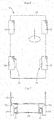
- FIG. 6 is a schematic plan view of an electric vehicle 11 on which in-wheel motor drive devices 21 according to the embodiment of the present invention are mounted
- FIG. 7 is a schematic sectional view of the electric vehicle when viewed from behind.
- the electric vehicle 11 comprises a chassis 12, front wheels 13 serving as steered wheels, rear wheels 14 serving as driving wheels, and the in-wheel motor drive devices 21 configured to transmit driving force to the right and left rear wheels 14, respectively.
- each rear wheel 14 is accommodated inside a wheel housing 12a of the chassis 12 and fixed below the chassis 12 through intermediation of a suspension device (suspension) 12b.
- a horizontally extending suspension arm supports the rear wheels 14, and a strut comprising a coil spring and a shock absorber absorbs vibrations that each rear wheel 14 receives from the ground to suppress vibrations of the chassis 12.
- a stabilizer configured to suppress tilting of a vehicle body during turning and other operations is provided at connecting portions of the right and left suspension arms.
- the suspension device 12b is desirably an independent suspension type capable of independently moving the right and left wheels up and down.
- the electric vehicle 11 need not comprise a motor, a drive shaft, a differential gear mechanism, and other components on the chassis 12 because the in-wheel motor drive devices 21 configured to drive the right and left rear wheels 14, respectively, are arranged inside the wheel housings 12a. Accordingly, the electric vehicle 11 has the advantages in that a large passenger compartment space can be provided and rotation of the right and left driving wheels can be controlled, respectively.
- the in-wheel motor drive device 21 is required to be downsized to provide a larger passenger compartment space. To this end, the in-wheel motor drive device 21 according to this embodiment is utilized as illustrated in FIG. 1 .
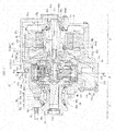
- FIG. 1 is a schematic longitudinal sectional view of the in-wheel motor drive device 21.
- FIG. 2 is a transverse sectional view taken along the line O-O of FIG. 1 .
- FIG. 3 is an explanatory view for illustrating a load acting on a curved plate.
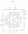
- FIG. 4 is a transverse sectional view of a rotary pump.
- FIG. 5 is an enlarged longitudinal sectional view of a rotation shaft of a motor having a rotor mounted thereto.
- the in-wheel motor drive device 21 comprises a motor part A configured to generate driving force, a speed reduction part B configured to reduce a speed of rotation of the motor part A to output the rotation, and a wheel bearing part C configured to transmit the output from the speed reduction part B to the driving wheel 14.
- the motor part A and the speed reduction part B are accommodated in a casing 22 and mounted inside the wheel housing 12a of the electric vehicle 11 as illustrated in FIG. 7 .
- the casing 22 is constructed such that the motor part A and the speed reduction part B are divisible from each other, and the motor part A and the speed reduction part B are fastened with bolts.
- the casing 22 refers to both of the casing portion accommodating the motor part A and the casing portion accommodating the speed reduction part B.
- the motor part A is a radial gap motor comprising a stator 23a fixed to the casing 22, a rotor 23b arranged inside the stator 23a at an opposed position with a radial gap, and a rotation shaft 24 of the motor, which is connected and fixed to the inside of the rotor 23b so as to rotate integrally with the rotor 23b.
- the rotation shaft 24 of the motor having the hollow structure is fitted and fixed to the radially inner surface of the rotor 23b to rotate integrally and is rotatably supported by a rolling bearing 36a at one end in its axial direction (right side in FIG. 1 ) and by a rolling bearing 36b at the other end in the axial direction (left side in FIG. 1 ) inside the motor part A.
- An input shaft 25 of the speed reducer is rotatably supported by a rolling bearing 37a at one approximately central portion in its axial direction (right side in FIG. 1 ) and by a rolling bearing 37b at the other end in the axial direction (left side in FIG. 1 ) with respect to an output shaft 28 of the speed reducer.
- the input shaft 25 of the speed reducer has eccentric portions 25a and 25b inside the speed reduction part B.
- the two eccentric portions 25a and 25b are arranged with a 180° phase shift to mutually cancel out centrifugal force caused by eccentric motion.
- the rotation shaft 24 of the motor and the input shaft 25 of the speed reducer are connected to each other by spline (including serration; the same applies hereinafter) fitting, and the driving force of the motor part A is transmitted to the speed reduction part B.
- the spline fitting portion is configured to suppress influences on the rotation shaft 24 of the motor even when the input shaft 25 of the speed reducer inclines to some extent.
- the speed reduction part B comprises curved plates 26a and 26b serving as revolving members rotatably held at the eccentric portions 25a and 25b, a plurality of outer pins 27 serving as outer periphery engagement members configured to engage with outer peripheral portions of the curved plates 26a and 26b, a motion conversion mechanism configured to transmit rotational motion of the curved plates 26a and 26b to the output shaft 28 of the speed reducer, and a counterweight 29 arranged at a position adjacent to the eccentric portions 25a and 25b.
- the output shaft 28 of the speed reducer has a flange portion 28a and a shaft portion 28b. At the end surface of the flange portion 28a, holes for fixing inner pins 31 are formed at equal intervals on the circumference about the rotation axis of the output shaft 28 of the speed reducer.
- the shaft portion 28b is connected to a hub wheel 32 serving as an inner member in the wheel bearing part C by spline fitting, to thereby transmit the output from the speed reduction part B to the wheel 14.
- the curved plate 26a has a plurality of wave patterns formed of trochoidal curves such as epitrochoidal curves in the outer periphery portion, and a plurality of through-holes 30a and a through-hole 30b each extending from one end surface to the other end surface.
- the plurality of through-holes 30a are formed at equal intervals on the circumference about the rotation axis of the curved plate 26a and are configured to receive the inner pins 31 to be described later.
- the through-hole 30b is formed at the center of the curved plate 26a, and the eccentric portion 25a is fitted thereinto.
- the curved plate 26a is rotatably supported by a rolling bearing 41 with respect to the eccentric portion 25a.
- the rolling bearing 41 is a cylindrical roller bearing comprising an inner ring 42 being fitted onto the radially outer surface of the eccentric portion 25a and having an inner raceway surface 42a on the radially outer surface, an outer raceway surface 43 directly formed at the radially inner surface of the through-hole 30b of the curved plate 26a, a plurality of cylindrical rollers 44 arranged between the inner raceway surface 42a and the outer raceway surface 43, and a cage (not shown) configured to retain the cylindrical rollers 44.
- the inner ring 42 has a flange portion projecting in a radially outward direction from both ends of the inner raceway surface 42a in the axial direction.
- the outer pins 27 are provided at equal intervals on the circumference about the rotation axis of the input shaft 25 of the speed reducer.
- curved wave patterns are engaged with the outer pins 27 to cause rotational motion of the curved plates 26a and 26b.
- Each outer pin 27 is rotatably supported on an outer pin housing 60 by a needle roller bearing 27a (see FIG. 1 ). The resistance of contact with the curved plates 26a and 26b can be therefore reduced.
- the counterweight 29 (see FIG. 1 ) has an approximately fan shape, has a through-hole into which the input shaft 25 of the speed reducer is fitted, and is arranged at a position adjacent to each of the eccentric portions 25a and 25b with a 180° phase shift with respect to the eccentric portions 25a and 25b in order to cancel out unbalanced inertia couple caused by the rotation of the curved plates 26a and 26b.
- the motion conversion mechanism comprises the plurality of inner pins 31 held on the output shaft 28 of the speed reducer and the through-holes 30a formed in the curved plates 26a and 26b.
- the inner pins 31 are provided at equal intervals on the circumference about the rotation axis of the output shaft 28 of the speed reducer (see FIG. 2 ), and each have one end in the axial direction fixed to the output shaft 28 of the speed reducer.
- a needle roller bearing 31a is provided at a position of contact with the inner wall surfaces of the through-holes 30a in the curved plates 26a and 26b.
- a stabilizer 31b is provided at the other ends of the inner pins 31 in the axial direction.
- the stabilizer 31b comprises an annular portion 31c having a circular ring shape and a cylindrical portion 31d extending axially from the radially inner surface of the annular portion 31c.
- the other ends of the plurality of inner pins 31 in the axial direction are fixed to the annular portion 31c.
- the load applied to some of the inner pins 31 from the curved plates 26a and 26b is supported by all the inner pins 31 through the stabilizer 31b. Therefore, the stress acting on the inner pins 31 can be reduced to improve the durability.
- the through-holes 30a are formed at positions corresponding to the plurality of inner pins 31, and the inner diameter dimension of each through-hole 30a is set to be larger by a predetermined dimension than the outer diameter dimension (corresponding to "maximum outer diameter including the needle roller bearing 31a"; the same applies hereinafter) of each inner pin 31.
- An axial center O 2 of the eccentric portion 25a is eccentric with respect to an axial center O of the input shaft 25 of the speed reducer by an amount of eccentricity e.
- the curved plate 26a is mounted to the outer periphery of the eccentric portion 25a, and the eccentric portion 25a rotatably supports the curved plate 26a. Accordingly, the axial center O 2 is also an axial center of the curved plate 26a.
- the outer periphery of the curved plate 26a is formed of a wavy curve, and the curved plate 26a has radially concave and wavy recesses 34 equiangularly.
- the plurality of outer pins 27 configured to engage with the recesses 34 are arranged in the circumferential direction about the axial center O.
- the curved plate 26a has the plurality of through-holes 30a formed in the circumferential direction about the axial center O 2 .
- the inner pin 31 configured to be joined to the output shaft 28 of the speed reducer, which is arranged coaxially with the axial center O, is inserted through each through-hole 30a.
- the inner diameter of each through-hole 30a is larger by a predetermined dimension than the outer diameter of each inner pin 31, and hence the inner pins 31 do not impede the revolving motion of the curved plate 26a, and the inner pins 31 utilize the rotational motion of the curved plate 26a to rotate the output shaft 28 of the speed reducer.
- the output shaft 28 of the speed reducer has a higher torque and a lower number of rotations than the input shaft 25 of the speed reducer, and the curved plate 26a is subjected to a load Fj from each of the plurality of inner pins 31, as indicated by the arrows in FIG. 3 .
- a resultant force Fs of the plurality of loads Fi and Fj is applied to the input shaft 25 of the speed reducer.
- the direction of the resultant force Fs varies depending on the geometric conditions such as the wavy shape of the curved plate 26a and the number of the recesses 34, and on the effect of centrifugal force. Specifically, an angle ⁇ formed between the resultant force Fs and a reference line X that is orthogonal to a straight line Y connecting the rotation axial center O 2 and the axial center O and passes through the axial center O 2 varies within a range of from approximately 30° to approximately 60°.
- the above-mentioned plurality of loads Fi and Fj vary in load direction and load magnitude during one rotation (360°) of the input shaft 25 of the speed reducer.
- the resultant force Fs acting on the input shaft 25 of the speed reducer also varies in load direction and load magnitude.
- One rotation of the input shaft 25 of the speed reducer causes speed reduction of the wavy recesses 34 of the curved plate 26a to rotate the curved plate 26a by one pitch in the clockwise direction to be brought into the state of FIG. 3 . This process is repeated.
- a wheel bearing 33 in the wheel bearing part C is a double-row angular contact ball bearing comprising an inner member formed of an inner raceway surface 33f directly formed at the radially outer surface of the hub wheel 32 and an inner ring 33a fitted onto a small-diameter step portion at the radially outer surface, an outer ring 33b fitted and fixed to the radially inner surface of the casing 22, a plurality of balls 33c serving as rolling elements arranged between the inner raceway surface 33f, the inner ring 33a, and the outer ring 33b, a cage 33d configured to keep the interval between the adjacent balls 33c, and a sealing member 33e configured to seal both ends of the wheel bearing 33 in the axial direction.
- the lubrication mechanism is configured to supply lubricating oil for cooling the motor part A, and also supply the lubricating oil to the speed reduction part B.
- the lubrication mechanism mainly comprises lubricating oil paths 24a and 25c, lubricating oil supply ports 24b, 25d, 25e, and 25f, a lubricating oil discharge port 22b, a lubricating oil reservoir 22d, a lubricating oil path 22e, a rotary pump 51, and a circulation oil path 45 as illustrated in FIG. 1 .
- the outline arrows in the lubrication mechanism indicate directions of lubricating oil flow.
- the lubricating oil path 25c which is connected to the lubricating oil path 24a of the rotation shaft 24 of the motor, extends along the axial direction inside the input shaft 25 of the speed reducer.
- the lubricating oil supply ports 25d and 25e extend from the lubricating oil path 25c toward the radially outer surface of the input shaft 25 of the speed reducer, and the lubricating oil supply port 25f extends from an axial end of the input shaft 25 of the speed reducer in a rotation axis direction toward an axial end surface.
- the lubricating oil discharge port 22b configured to discharge the lubricating oil inside the speed reduction part B is formed at least at one location of the casing 22 at the position of the speed reduction part B. Further, the lubricating oil reservoir 22d configured to temporarily store the discharged lubricating oil is formed.
- the circulation oil path 45 comprises an axial oil path 45a axially extending inside the casing 22, a radial oil path 45c being connected to one end of the axial oil path 45a in the axial direction (right side in FIG. 1 ) and extending in the radial direction, and a radial oil path 45b being connected to the other end of the axial oil path 45a in the axial direction (left side in FIG. 1 ) and extending in the radial direction.
- the rotary pump 51 is provided between the circulation oil path 45 and the lubricating oil path 22e connected to the lubricating oil reservoir 22d.
- the radial oil path 45b supplies lubricating oil force-fed through the rotary pump 51 to the axial oil path 45a and supplies the lubricating oil from the axial oil path 45a to each of the lubricating oil paths 24a and 25c through the radial oil path 45c.
- the rotary pump 51 is a cycloid pump comprising an inner rotor 52 configured to rotate using the rotation of the output shaft 28 of the speed reducer, an outer rotor 53 configured to be driven to rotate in conjunction with the rotation of the inner rotor 52, pump chambers 54, a suction port 55 communicating with the lubricating oil path 22e, and a discharge port 56 communicating with the radial oil path 45b of the circulation oil path 45.
- Increase in size of the overall in-wheel motor drive device 21 can be prevented by arranging the rotary pump 51 inside the casing 22.
- the inner rotor 52 rotates about a rotation center c 1
- the outer rotor 53 rotates about a rotation center c 2
- the inner rotor 52 and the outer rotor 53 rotate about the different rotation centers c 1 and c 2 , and hence the volume of each pump chamber 54 changes continuously.
- the lubricating oil entering through the suction port 55 is force-fed through the discharge port 56 to the radial oil path 45b.
- the motor part A is cooled as follows. As illustrated in FIG. 1 , a part of the lubricating oil returned to the lubricating oil path 24a through the circulation oil path 45 flows through the lubricating oil supply port 24b under centrifugal force to cool the rotor 23b. After that, the lubricating oil splashes to cool the stator 23a.
- the speed reduction part B is lubricated as follows.
- the lubricating oil in the lubricating oil path 25c flows out through the lubricating oil supply ports 25d and 25e to enter the speed reduction part B under centrifugal force and pressure caused along with the rotation of the input shaft 25 of the speed reducer.
- the lubricating oil flowing out through the lubricating oil supply port 25d lubricates the cylindrical roller bearing 41 supporting each of the curved plates 26a and 26b, and moves radially outward under centrifugal force while lubricating, for example, portions of contact between each of the curved plates 26a and 26b and the inner pins 31, and portions of contact between each of the curved plates 26a and 26b and the outer pins 27.
- the lubricating oil flowing out through the lubricating oil supply ports 25e and 25f is supplied to the deep groove ball bearings 37a and 37b supporting the input shaft 25 of the speed reducer, and further to the internal bearings and the contact portions.
- the lubricating oil having reached the inner wall surface of the casing 22 is discharged through the lubricating oil discharge port 22b to be stored in the lubricating oil reservoir 22d.
- the lubricating oil reservoir 22d is provided between the lubricating oil discharge port 22b and the rotary pump 51. Therefore, even when a part of the lubricating oil cannot temporarily be discharged by the rotary pump 51, the lubricating oil can be stored in the lubricating oil reservoir 22d. As a result, increase in torque loss of the speed reduction part B can be prevented.
- the lubricating oil stored in the lubricating oil reservoir 22d can be returned to the lubricating oil paths 24a and 25c by the rotary pump 51.
- the lubricating oil moves under the gravity in addition to the centrifugal force. Therefore, the lubricating oil reservoir 22d is desirably mounted to the electric vehicle 11 so as to be located below the in-wheel motor drive device 21.
- the overall configuration of the in-wheel motor drive device 21 according to this embodiment is as described above.
- a characteristic configuration of the in-wheel motor drive device 21 is described below.
- the stator 23a is fixed to the casing 22, and the rotor 23b is arranged inside the stator 23a at an opposed position with a radial gap.
- the rotor 23b is fitted and fixed to the outside of the rotation shaft 24 of the motor to rotate integrally with the rotation shaft 24 of the motor.
- the rotation shaft 24 of the motor is rotatably supported by the deep groove ball bearing 36a being the rolling bearing at one end in the axial direction (right side in FIG. 1 ) and by the deep groove ball bearing 36b being the rolling bearing at the other end in the axial direction (left side in FIG. 1 ) inside the casing 22.
- the rotation shaft 24 of the motor rotates at a high speed of about 15,000 min -1 .
- inner rings 36a1 and 36b1 of the deep groove ball bearings 36a and 36b and the rotation shaft 24 of the motor are fitted to each other by transition fit or interference fit, whereas outer rings 36a2 and 36b2 of the deep groove ball bearings 36a and 36b and the casing 22 are fitted to each other by clearance fit.
- a preload is applied to each of the deep groove ball bearings 36a and 36b in the axial direction.
- FIG. 5 is an enlarged longitudinal sectional view of the rotation shaft of the motor and the rotor.
- the rotation shaft 24 of the motor is made of case hardening steel such as SCM415 or SCM420, and is subjected to carburizing, quenching, and tempering.
- a heat-treated hardened layer H is indicated by cross hatching.
- the surface of the rotation shaft 24 of the motor, which is subjected to carburizing, quenching, and tempering has a high hardness of from 62 HRC to 66.5 HRC.
- the central portion has a hardness of from about 29 HRC to about 38 HRC.
- a large-diameter radially outer portion 61 of the rotation shaft 24 of the motor is a portion to which the rotor 23b is fitted.
- a flange portion 62 configured to hold the rotor 23b in the axial direction is formed at one end of the large-diameter radially outer portion 61.
- An outer surface 62a of the flange portion 62 is subjected to anti-carburizing treatment, and has a hardness of from about 29 HRC to about 38 HRC.
- the large-diameter radially outer portion 61 of the rotation shaft 24 of the motor and a radially inner portion of the rotor 23b are fitted to each other by interference fit or shrink fit with an interference selected in consideration of expansion caused by centrifugal force and thermal expansion.
- the large-diameter radially outer portion 61 of the rotation shaft 24 of the motor and the radially inner portion of the rotor 23b are press-fitted in contact with each other.
- the large-diameter radially outer portion 61 is formed to have high surface hardness, thereby being capable of preventing abrasion of the contact portion.
- a separate clamping member 63 is brought into abutment against the other end of the rotor 23b to be fixed by fastening with a bolt 64.
- the rotor 23b is mounted to the rotation shaft 24 of the motor.
- the clamping member 63 there is selected a material having high specific gravity, and also having non-magnetic property so that shavings to be generated by cutting work for adjustment of unbalance described later are not attracted to the rotor 23b.
- austenitic stainless steel is desired.
- aluminum is not preferred because the specific gravity is low.
- tungsten and copper may be used, but the cost is increased.
- Heat-treated hardened layers are also formed on bearing mounting surfaces 65 and 66 at both ends of the rotation shaft 24 of the motor in the axial direction.
- the inner rings 36a1 and 36b1 of the deep groove ball bearings 36a and 36b and the bearing mounting surfaces 65 and 66 of the rotation shaft 24 of the motor are fitted to each other by transition fit or interference fit, respectively. Due to the heat-treated hardened layers formed on the bearing mounting surfaces 65 and 66, the inner rings 36a1 and 36b1 do not damage the bearing mounting surfaces 65 and 66 at the time of assembling, respectively.
- the in-wheel motor drive device is suitable as an in-wheel motor drive device in which a low-torque high-rotation motor and a cycloid reducer capable of obtaining a high speed reduction ratio are used in combination.
- the outer surface 62a of the flange portion 62 of the large-diameter radially outer portion 61 and the outer surface of the clamping member 63 are surfaces for correction of balance.
- the outer surface 62a of the flange portion 62 and the outer surface of the clamping member 63 are set as the surfaces for correction of balance because the surfaces are preferably formed as nearly on the radially outer side as possible in order to reduce the cutting amount for the adjustment of unbalance.
- the present invention is not limited thereto, and any one of the outer surface 62a of the flange portion 62 and the outer surface of the clamping member 63 may be set as the surface for correction of balance.
- the outer surface 62a of the flange portion 62 is subjected to anti-carburizing treatment to have low hardness, thereby being capable of achieving satisfactory cutting work for the adjustment of unbalance, reducing the cycle time of the cutting step, facilitating the adjustment of unbalance, and reducing the cost.
- the clamping member 63 has high specific gravity, thereby being capable of reducing the processing amount, reducing the cycle time of the cutting step, facilitating the adjustment of unbalance, and reducing the cost.
- the anti-carburizing treatment for the flange portion 62 may be implemented by any appropriate methods such as a method that involves applying an anti-carburizing agent onto the outer surface 62a and a method that involves carburizing while bringing a jig into surface contact with the outer surface 62a.
- the carburizing and quenching are flexible in response to minor changes to the shape and also simple to discriminate the heat treatment portion and the non-heat treatment portion of the rotation shaft 24 of the motor, thereby being advantageous in terms of cost.
- the rotation shaft 24 of the motor having the rotor 23b mounted thereto have a permissible residual specific unbalance within a range of from 0.5 to 5 after the adjustment of unbalance.
- the permissible residual specific unbalance refers to, in conformity with JIS B 0905, an amount obtained by dividing a permissible residual unbalance, which corresponds to the magnitude of the maximum permissible residual unbalance, by the mass of the rotor.
- the permissible residual specific unbalance within the range of from 0.5 to 5 corresponds to a balance quality grade of from G1 to G6.3 as specified in JIS.
- G1 Class is required for grinding-wheel spindles
- G2.5 Class is required for machine-tool spindles, gas turbines, and jet turbine-driven pumps
- G6.3 Class is required for pumps and fans of general industrial machinery, and general pneumatic and hydraulic machinery.
- the permissible residual specific unbalance is set within the range of from 0.5 to 5, thereby being capable of suppressing interior vibrations, achieving excellent quietness, and preventing passengers' feelings of discomfort.
- the other end of the rotation shaft 24 of the motor in the axial direction (left side in FIG. 1 ) is connected to the input shaft 25 of the speed reducer by spline fitting.
- the spline fitting portion is affected by the operation of the speed reduction part B.
- the outer pin housing 60 configured to hold the outer pins 27 of the speed reduction part B as illustrated in FIG. 1 is supported on the casing 22 in a floating state by a rotation stopper (not shown) having an elastic support function.
- the radial and moment loads which vary in load direction and load magnitude, are applied to the input shaft 25 of the speed reducer from each of the curved plates 26a and 26b as described above. Therefore, the torque is transmitted at the spline fitting portion between the rotation shaft 24 of the motor and the input shaft 25 of the speed reducer under a state in which inclination or axial misalignment is caused to some extent.
- the rotation shaft 24 of the motor is made of case hardening steel and subjected to carburizing, quenching, and tempering as heat treatment. Thus, the rotation shaft 24 of the motor has sufficient abrasion resistance, thereby being capable of enhancing the durability.
- the in-wheel motor drive device 21 comprises the rotation shaft 24 of the motor, which has excellent processability and abrasion resistance at the fitting portion, has required surface hardness and toughness, facilitates the adjustment of unbalance, and has an advantage in terms of cost.
- the in-wheel motor drive device 21 according to this embodiment can be reduced in size and weight, excellent in quietness, and enhanced in durability.
- coils in the stator 23a are supplied with AC current to generate an electromagnetic force, which in turn rotates the rotor 23b formed of a permanent magnet or a magnetic member.
- the input shaft 25 of the speed reducer which is connected to the rotation shaft 24 of the motor, is therefore rotated to cause the curved plates 26a and 26b to revolve about the rotation axis of the input shaft 25 of the speed reducer.
- the outer pins 27 come into engagement with the curved wave patterns of the curved plates 26a and 26b to rotate the curved plates 26a and 26b on their axes in an opposite direction to the rotation of the input shaft 25 of the speed reducer.
- the inner pins 31 inserted through the through-holes 30a come into contact with the inner wall surfaces of the through-holes 30a in conjunction with the rotational motion of the curved plates 26a and 26b.
- the revolving motion of the curved plates 26a and 26b is therefore prevented from being transmitted to the inner pins 31, and only the rotational motion of the curved plates 26a and 26b is transmitted to the wheel bearing part C through the output shaft 28 of the speed reducer.
- the speed reduction ratio in the speed reduction part B having the above-mentioned configuration is calculated by (Z A -Z B )/Z B .
- a very high speed reduction ratio of 1/11 can be obtained.
- the in-wheel motor drive device 21 that is compact and has a high speed reduction ratio can be obtained by using the speed reduction part B capable of obtaining a high speed reduction ratio without requiring a multi-stage configuration.
- the needle roller bearings 27a and 31a are provided to the outer pins 27 and the inner pins 31, respectively, to reduce the frictional resistance between those pins and the curved plates 26a and 26b, thereby improving the transmission efficiency of the speed reduction part B.
- the unsprung weight can be reduced by mounting the in-wheel motor drive device 21 according to this embodiment on the electric vehicle 11. As a result, the electric vehicle 11 having excellent driving stability and NVH characteristics can be obtained.
- the lubricating oil supply port 24b is formed in the rotation shaft 24 of the motor
- the lubricating oil supply port 25e is formed in the vicinity of the rolling bearing 37a
- the lubricating oil supply port 25d is formed in each of the eccentric portions 25a and 25b
- the lubricating oil supply port 25f is formed in the axial end of the input shaft 25 of the speed reducer.
- the present invention is not limited thereto, and the lubricating oil supply ports may be formed at any positions in the rotation shaft 24 of the motor and the input shaft 25 of the speed reducer.
- a cycloid pump is used as the rotary pump 51, but the present invention is not limited thereto. Any rotary pump that is driven using the rotation of the output shaft 28 of the speed reducer may be employed. Further, the rotary pump 51 may be omitted so that the lubricating oil is circulated only by centrifugal force.
- the number of curved plates may be arbitrarily set and in a case where three curved plates are arranged, for example, the three curved plates may be arranged with a 120° phase shift.
- the motion conversion mechanism comprises the inner pins 31 fixed to the output shaft 28 of the speed reducer and the through-holes 30a formed in the curved plates 26a and 26b.
- the present invention is not limited thereto. Any configuration may be applied as long as the rotation of the speed reduction part B can be transmitted to the hub wheel 32.
- the motion conversion mechanism may comprise inner pins fixed to the curved plates and holes formed in the output shaft of the speed reducer.
- a brake may also be added to the configuration in this embodiment.
- the casing 22 may be extended in its axial direction to form a space on the right side of the rotor 23b in FIG. 1 , and a rotary member configured to rotate integrally with the rotor 23b, a piston non-rotatable with respect to the casing 22 and movable in its axial direction, and a cylinder configured to operate the piston may be arranged, thereby constructing a parking brake in which the rotor 23b is locked by the piston and the rotary member while a vehicle is stopped.
- a disc brake in which a flange formed at a part of a rotary member configured to rotate integrally with the rotor 23b and a friction plate arranged on the casing 22 side are sandwiched using a cylinder arranged on the casing 22 side.
- a drum brake in which a drum is formed at a part of a rotary member and a brake shoe is fixed on the casing 22 side so that the rotary member is locked by the actions of frictional engagement and self-engagement.
- a radial gap motor is employed in the motor part A.
- the present invention is not limited thereto, and a motor having arbitrary configuration is applicable.
- an axial gap motor comprising a stator to be fixed to a casing, and a rotor arranged on the inner side of the stator at an opposed position with an axial gap.
Landscapes
- Engineering & Computer Science (AREA)
- General Engineering & Computer Science (AREA)
- Power Engineering (AREA)
- Mechanical Engineering (AREA)
- Chemical & Material Sciences (AREA)
- Transportation (AREA)
- Combustion & Propulsion (AREA)
- Manufacturing & Machinery (AREA)
- Arrangement Or Mounting Of Propulsion Units For Vehicles (AREA)
- Mounting Of Bearings Or Others (AREA)
- Rolling Contact Bearings (AREA)
- Iron Core Of Rotating Electric Machines (AREA)
- Connection Of Motors, Electrical Generators, Mechanical Devices, And The Like (AREA)
Abstract
Description
- The present invention relates to an in-wheel motor drive device.
- The related-art in-wheel motor drive device is described in, for example,
JP 2012-148725 A JP 2012-148725 A - In the above-mentioned in-wheel motor drive device, a low-torque high-rotation motor is utilized in the motor part from the viewpoint of device compactness. Meanwhile, the wheel bearing part requires a large torque for driving the wheel. Therefore, a cycloid reducer capable of obtaining a high speed reduction ratio with a compact size is utilized.
- The motor part is a radial gap motor including a stator fixed to a casing, a rotor arranged inside the stator at an opposed position with a radial gap, and a rotation shaft of the motor, which is connected and fixed to the inside of the rotor to rotate integrally with the rotor. Both axial ends of the rotation shaft of the motor having the hollow structure are rotatably supported on the casing by a pair of rolling bearings.
- The speed reduction part in which the cycloid reducer is utilized mainly includes an input shaft of the speed reducer having a pair of eccentric parts, a pair of curved plates arranged at the eccentric parts, respectively, a plurality of outer periphery engagement members configured to engage with outer peripheral surfaces of the curved plates to cause rotational motion of the curved plates, and a plurality of inner pins configured to transmit the rotational motion of the curved plates to an output shaft of the speed reducer. The above-mentioned rotation shaft of the motor is spline-connected to the input shaft of the speed reducer.
- Patent Document 1:
JP 2012-148725 A - Incidentally, the in-wheel motor drive device is accommodated inside a wheel housing to increase the unsprung weight. Therefore, downsizing and light-weighting are essential to the in-wheel motor drive device. However, the output torque of the motor is proportional to the size of the motor, and hence a large-sized motor is required to generate a torque necessary for driving the vehicle with the motor alone. As a result, the weight is increased. In view of this, a speed reducer is combined with the motor, thereby being capable of downsizing the motor. When the speed reduction ratio is increased to achieve a small-sized motor, the rotation speed needs to be increased inevitably. For example, the use of a speed reducer having a speed reduction ratio of 11 requires a high rotation speed of about 15,000 min-1.
- The in-wheel motor drive device is mounted under a spring of the vehicle, and hence vibrations of the in-wheel motor drive device significantly affect the ride comfort of the vehicle. Further, the in-wheel motor drive device is shifted from zero-speed to a high-speed range, thereby causing vibrations and interior noises within an audible range at a point at which resonance on the periphery of a suspension device and a forced vibration component cross each other. As a result, passengers may have a feeling of discomfort. Thus, reduction of a rotational first-order forced vibration component, which leads to all kinds of vibrations, may significantly contribute to quietness of the vehicle.
- The in-wheel motor drive device described in Patent Document 1 has room for improvement to address the above-mentioned problem.
- The present invention has been proposed in view of the above-mentioned problem, and has an object to provide an in-wheel motor drive device that is reduced in size and weight, excellent in quietness, and is enhanced in durability.
- The present invention is based on the following findings obtained through investigations to achieve the above-mentioned object, which have been conducted from various viewpoints for a rotation shaft of a motor having a rotor mounted thereto in an in-wheel motor drive device.
- Adjustment of the amount of unbalance in the rotation shaft of the motor having the rotor mounted thereto, which is a high-speed spindle, is essential to suppress vibrations, and the easiness of adjustment in mass production apparatus for automobiles affects the cost. Specifically, as a method of adjusting unbalance, there are given a method of adjusting unbalance by adding a weight, and a method of adjusting unbalance by cutting a part of the spindle. The addition of a weight to a high-speed rotary member may result in detachment of the weight during rotation, and hence the method of adjusting unbalance by cutting is selected in general.
- The adjustment of unbalance is performed when the assembling is completed to obtain the rotation shaft of the motor having the rotor mounted thereto, and hence the cutting work is performed after heat treatment. When the hardness of the surface to be processed for the adjustment of unbalance is high, the surface is difficult to cut, resulting in low processability. Due to the low processability, the cycle time of the cutting step becomes longer, thus leading to cost increase. On the other hand, when the hardness of the surface to be processed for the adjustment of unbalance is low and close to the hardness of a raw material, the surface is easy to cut, resulting in satisfactory processability. Due to the satisfactory processability, the cycle time of the cutting step becomes shorter, thus leading to cost reduction. Low-carbon steel is desired as a steel grade in which satisfactory processability is secured as a raw material.
- Heat treatment is performed for the high-speed spindle in order to enhance the abrasion resistance at the fitting portion. Through the heat treatment, the surface hardness is increased. Thus, it has been found desirable to satisfy both conflicting demands for enhancing the processability and the easiness of heat treatment.
- The rotation shaft of the motor having the rotor mounted thereto includes the rotation shaft of the motor, which is supported by rolling bearings at both ends of the rotation shaft of the motor, and the rotor, which is formed of magnets and silicon steel plates. It is preferred that the rotation shaft of the motor and the rotor be fitted to each other by interference fit or shrink fit with an interference selected in consideration of expansion caused by centrifugal force and thermal expansion. In the case of interference fit, a radially outer portion of the rotation shaft of the motor and a radially inner portion of the rotor are press-fitted in contact with each other at the time of assembling. Therefore, the radially outer portion of the rotation shaft of the motor is required to have high surface hardness for the purpose of enhancing the abrasion resistance at the contact portion.
- For the rolling bearings configured to support the rotation shaft of the motor, it is desired that inner rings of the bearings and the rotation shaft of the motor be fitted to each other by interference fit from the viewpoint of suppressing vibrations. The fitting portion of the rotation shaft of the motor is required to have high surface hardness in order to prevent the bearings from damaging the fitting portion of the rotation shaft of the motor at the time of assembling.
- Further, the compactness of the in-wheel motor drive device is achieved by connecting the motor part and the speed reduction part. A spline fitting portion serving as a torque transmitting portion between the motor part and the speed reduction part is required to have abrasion resistance and strength, and surface treatment or heat treatment is therefore essential. Thus, it has been found that easier heat treatment is preferred.
- The rotation shaft of the motor is also required to have toughness high enough to be durable against deformation during high-speed rotation. As a material capable of obtaining high surface hardness and toughness of the central portion, there are given case hardening steel to be subjected to carburizing and quenching, and medium carbon steel to be subjected to induction hardening. From the viewpoint of surface hardness, high-carbon chromium bearing steel may also be selected. However, in a case of through-hardening, it has been found that, in a shape having a large-diameter portion as in the case of the rotation shaft of the motor, quenching cracks may be generated during a rapid cooling step after heating due to a temperature gradient between the central portion and the surface portion.
- It is preferred that the material be easily available and inexpensive. As a material having high strength, high-carbon chromium bearing steel is given, but the cost is high. Besides, induction hardening using medium carbon steel is conceivable, but in this case, a dedicated heating coil needs to be manufactured, resulting in lack of flexibility in response to minor changes to the shape. In contrast, carburizing and quenching using case hardening steel are flexible in response to minor changes to the shape and also simple to discriminate the heat treatment portion and the non-heat treatment portion of the rotation shaft of the motor. Further, it has been found that case hardening steel is desired in terms of processability of the raw material and easiness of heat treatment.
- As a technical measure to achieve the above-mentioned object, according to one embodiment of the present invention, there is provided an in-wheel motor drive device, comprising: a motor part; a speed reduction part; a wheel bearing part; and a casing, the motor part comprising: a stator, which is fixed to the casing; a rotation shaft of a motor, which is rotatably supported on the casing through intermediation of a plurality of rolling bearings; and a rotor, which is mounted to the rotation shaft of the motor, the rotation shaft of the motor in the motor part being configured to rotationally drive an input shaft of a speed reducer in the speed reduction part, the speed reduction part being configured to reduce a speed of rotation of the input shaft of the speed reducer to transmit the rotation to an output shaft of the speed reducer, the wheel bearing part being connected to the output shaft of the speed reducer, the rotation shaft of the motor being made of case hardening steel and subjected to carburizing, quenching, and tempering as heat treatment.
- With the configuration described above, it is possible to achieve the in-wheel motor drive device comprising the rotation shaft of the motor, which has excellent processability and abrasion resistance at the fitting portion, has required surface hardness and toughness, facilitates the adjustment of unbalance, and has an advantage in terms of cost, so that the in-wheel motor drive device is reduced in size and weight, excellent in quietness, and is enhanced in durability.
- It is desired that the above-mentioned rotation shaft of the motor comprise a flange portion to be brought into contact with one end of the rotor, that the motor part further comprise a clamping member to be brought into contact with another end of the rotor, that the rotor be clamped by the flange portion and the clamping member to be mounted to the rotation shaft of the motor, and that the flange portion comprise a low-hardness portion for adjustment of unbalance. In this case, the surfaces for correction of unbalance can be formed on the radially outer side, thereby being capable of reducing the cutting amount for the adjustment of unbalance, facilitating the adjustment of unbalance, and reducing the cost.
- The above-mentioned low-hardness portion may be formed through anti-carburizing treatment. This process is flexible in response to minor changes to the shape of the rotation shaft of the motor and also simple to discriminate the heat treatment portion and the non-heat treatment portion, thereby being advantageous in terms of cost.
- It is preferred that the rotation shaft of the motor having the above-mentioned rotor mounted thereto have a permissible residual specific unbalance of from 0.5 to 5 after the adjustment of unbalance. Thus, it is possible to suppress interior vibrations, achieve excellent quietness, and to prevent passengers' feelings of discomfort.
- The above-mentioned clamping member may be made of a material different from a material for a rotary member. Thus, it is possible to select a material having high specific gravity, and also having non-magnetic property so that shavings to be generated by the cutting work for the adjustment of unbalance are not attracted to the rotor.
- It is preferred that the above-mentioned clamping member be made of austenitic stainless steel. Thus, the material has non-magnetic property and high specific gravity, and is advantageous in terms of cost.
- According to the in-wheel motor drive device of the present invention, it is possible to achieve the in-wheel motor drive device that is reduced in size and weight, excellent in quietness, and is enhanced in durability.
-
-
FIG. 1 is a view for illustrating an in-wheel motor drive device according to an embodiment of the present invention. -
FIG. 2 is a transverse sectional view taken along the line O-O ofFIG. 1 . -
FIG. 3 is an explanatory view for illustrating a load acting on a curved plate ofFIG. 1 . -
FIG. 4 is a transverse sectional view of a rotary pump ofFIG. 1 . -
FIG. 5 is an enlarged longitudinal sectional view of a rotation shaft of a motor having a rotor ofFIG. 1 mounted thereto. -
FIG. 6 is a plan view of an electric vehicle on which the in-wheel motor drive devices ofFIG. 1 are mounted. -
FIG. 7 is a rear sectional view of the electric vehicle ofFIG. 6 . - An in-wheel motor drive device according to an embodiment of the present invention is described with reference to
FIG. 1 to FIG. 7 . -
FIG. 6 is a schematic plan view of anelectric vehicle 11 on which in-wheelmotor drive devices 21 according to the embodiment of the present invention are mounted, andFIG. 7 is a schematic sectional view of the electric vehicle when viewed from behind. As illustrated inFIG. 6 , theelectric vehicle 11 comprises achassis 12,front wheels 13 serving as steered wheels,rear wheels 14 serving as driving wheels, and the in-wheelmotor drive devices 21 configured to transmit driving force to the right and leftrear wheels 14, respectively. As illustrated inFIG. 7 , eachrear wheel 14 is accommodated inside awheel housing 12a of thechassis 12 and fixed below thechassis 12 through intermediation of a suspension device (suspension) 12b. - In the
suspension device 12b, a horizontally extending suspension arm supports therear wheels 14, and a strut comprising a coil spring and a shock absorber absorbs vibrations that eachrear wheel 14 receives from the ground to suppress vibrations of thechassis 12. In addition, a stabilizer configured to suppress tilting of a vehicle body during turning and other operations is provided at connecting portions of the right and left suspension arms. In order to improve the property of following irregularities of a road surface to transmit the driving force of the driving wheels to the road surface efficiently, thesuspension device 12b is desirably an independent suspension type capable of independently moving the right and left wheels up and down. - The
electric vehicle 11 need not comprise a motor, a drive shaft, a differential gear mechanism, and other components on thechassis 12 because the in-wheelmotor drive devices 21 configured to drive the right and leftrear wheels 14, respectively, are arranged inside thewheel housings 12a. Accordingly, theelectric vehicle 11 has the advantages in that a large passenger compartment space can be provided and rotation of the right and left driving wheels can be controlled, respectively. - It is necessary to reduce the unsprung weight in order to improve the driving stability and the NVH characteristics of the
electric vehicle 11. In addition, the in-wheelmotor drive device 21 is required to be downsized to provide a larger passenger compartment space. To this end, the in-wheelmotor drive device 21 according to this embodiment is utilized as illustrated inFIG. 1 . - The in-wheel
motor drive device 21 according to the embodiment of the present invention is described with reference toFIG. 1 to FIG. 5 .FIG. 1 is a schematic longitudinal sectional view of the in-wheelmotor drive device 21.FIG. 2 is a transverse sectional view taken along the line O-O ofFIG. 1 .FIG. 3 is an explanatory view for illustrating a load acting on a curved plate.FIG. 4 is a transverse sectional view of a rotary pump.FIG. 5 is an enlarged longitudinal sectional view of a rotation shaft of a motor having a rotor mounted thereto. Prior to the description of a characteristic configuration of the in-wheel motor drive device according to this embodiment, an overall configuration of the in-wheel motor drive device is described. - As illustrated in
FIG. 1 , the in-wheelmotor drive device 21 comprises a motor part A configured to generate driving force, a speed reduction part B configured to reduce a speed of rotation of the motor part A to output the rotation, and a wheel bearing part C configured to transmit the output from the speed reduction part B to thedriving wheel 14. The motor part A and the speed reduction part B are accommodated in acasing 22 and mounted inside thewheel housing 12a of theelectric vehicle 11 as illustrated inFIG. 7 . In this embodiment, thecasing 22 is constructed such that the motor part A and the speed reduction part B are divisible from each other, and the motor part A and the speed reduction part B are fastened with bolts. In this description and the claims, thecasing 22 refers to both of the casing portion accommodating the motor part A and the casing portion accommodating the speed reduction part B. - The motor part A is a radial gap motor comprising a
stator 23a fixed to thecasing 22, arotor 23b arranged inside thestator 23a at an opposed position with a radial gap, and arotation shaft 24 of the motor, which is connected and fixed to the inside of therotor 23b so as to rotate integrally with therotor 23b. - The
rotation shaft 24 of the motor having the hollow structure is fitted and fixed to the radially inner surface of therotor 23b to rotate integrally and is rotatably supported by a rollingbearing 36a at one end in its axial direction (right side inFIG. 1 ) and by a rollingbearing 36b at the other end in the axial direction (left side inFIG. 1 ) inside the motor part A. - An
input shaft 25 of the speed reducer is rotatably supported by a rollingbearing 37a at one approximately central portion in its axial direction (right side inFIG. 1 ) and by a rollingbearing 37b at the other end in the axial direction (left side inFIG. 1 ) with respect to anoutput shaft 28 of the speed reducer. Theinput shaft 25 of the speed reducer haseccentric portions eccentric portions - The
rotation shaft 24 of the motor and theinput shaft 25 of the speed reducer are connected to each other by spline (including serration; the same applies hereinafter) fitting, and the driving force of the motor part A is transmitted to the speed reduction part B. The spline fitting portion is configured to suppress influences on therotation shaft 24 of the motor even when theinput shaft 25 of the speed reducer inclines to some extent. - The speed reduction part B comprises
curved plates 26a and 26b serving as revolving members rotatably held at theeccentric portions outer pins 27 serving as outer periphery engagement members configured to engage with outer peripheral portions of thecurved plates 26a and 26b, a motion conversion mechanism configured to transmit rotational motion of thecurved plates 26a and 26b to theoutput shaft 28 of the speed reducer, and acounterweight 29 arranged at a position adjacent to theeccentric portions - The
output shaft 28 of the speed reducer has aflange portion 28a and ashaft portion 28b. At the end surface of theflange portion 28a, holes for fixinginner pins 31 are formed at equal intervals on the circumference about the rotation axis of theoutput shaft 28 of the speed reducer. Theshaft portion 28b is connected to ahub wheel 32 serving as an inner member in the wheel bearing part C by spline fitting, to thereby transmit the output from the speed reduction part B to thewheel 14. - As illustrated in
FIG. 2 , thecurved plate 26a has a plurality of wave patterns formed of trochoidal curves such as epitrochoidal curves in the outer periphery portion, and a plurality of through-holes 30a and a through-hole 30b each extending from one end surface to the other end surface. The plurality of through-holes 30a are formed at equal intervals on the circumference about the rotation axis of thecurved plate 26a and are configured to receive theinner pins 31 to be described later. The through-hole 30b is formed at the center of thecurved plate 26a, and theeccentric portion 25a is fitted thereinto. - The
curved plate 26a is rotatably supported by a rollingbearing 41 with respect to theeccentric portion 25a. As illustrated inFIG. 2 , the rollingbearing 41 is a cylindrical roller bearing comprising aninner ring 42 being fitted onto the radially outer surface of theeccentric portion 25a and having aninner raceway surface 42a on the radially outer surface, an outer raceway surface 43 directly formed at the radially inner surface of the through-hole 30b of thecurved plate 26a, a plurality ofcylindrical rollers 44 arranged between theinner raceway surface 42a and the outer raceway surface 43, and a cage (not shown) configured to retain thecylindrical rollers 44. Theinner ring 42 has a flange portion projecting in a radially outward direction from both ends of theinner raceway surface 42a in the axial direction. - As illustrated in
FIG. 2 , theouter pins 27 are provided at equal intervals on the circumference about the rotation axis of theinput shaft 25 of the speed reducer. As a result of revolving motion of thecurved plates 26a and 26b, curved wave patterns are engaged with theouter pins 27 to cause rotational motion of thecurved plates 26a and 26b. Eachouter pin 27 is rotatably supported on anouter pin housing 60 by aneedle roller bearing 27a (seeFIG. 1 ). The resistance of contact with thecurved plates 26a and 26b can be therefore reduced. - The counterweight 29 (see
FIG. 1 ) has an approximately fan shape, has a through-hole into which theinput shaft 25 of the speed reducer is fitted, and is arranged at a position adjacent to each of theeccentric portions eccentric portions curved plates 26a and 26b. - As illustrated in
FIG. 1 , the motion conversion mechanism comprises the plurality ofinner pins 31 held on theoutput shaft 28 of the speed reducer and the through-holes 30a formed in thecurved plates 26a and 26b. The inner pins 31 are provided at equal intervals on the circumference about the rotation axis of theoutput shaft 28 of the speed reducer (seeFIG. 2 ), and each have one end in the axial direction fixed to theoutput shaft 28 of the speed reducer. In order to reduce the resistance of friction against thecurved plates 26a and 26b, aneedle roller bearing 31a is provided at a position of contact with the inner wall surfaces of the through-holes 30a in thecurved plates 26a and 26b. - A
stabilizer 31b is provided at the other ends of theinner pins 31 in the axial direction. Thestabilizer 31b comprises anannular portion 31c having a circular ring shape and a cylindrical portion 31d extending axially from the radially inner surface of theannular portion 31c. The other ends of the plurality ofinner pins 31 in the axial direction are fixed to theannular portion 31c. The load applied to some of theinner pins 31 from thecurved plates 26a and 26b is supported by all theinner pins 31 through thestabilizer 31b. Therefore, the stress acting on theinner pins 31 can be reduced to improve the durability. - The through-
holes 30a are formed at positions corresponding to the plurality ofinner pins 31, and the inner diameter dimension of each through-hole 30a is set to be larger by a predetermined dimension than the outer diameter dimension (corresponding to "maximum outer diameter including theneedle roller bearing 31a"; the same applies hereinafter) of eachinner pin 31. - The state of the load acting on each of the
curved plates 26a and 26b is described with reference toFIG. 3 . An axial center O2 of theeccentric portion 25a is eccentric with respect to an axial center O of theinput shaft 25 of the speed reducer by an amount of eccentricity e. Thecurved plate 26a is mounted to the outer periphery of theeccentric portion 25a, and theeccentric portion 25a rotatably supports thecurved plate 26a. Accordingly, the axial center O2 is also an axial center of thecurved plate 26a. The outer periphery of thecurved plate 26a is formed of a wavy curve, and thecurved plate 26a has radially concave andwavy recesses 34 equiangularly. On the periphery of thecurved plate 26a, the plurality ofouter pins 27 configured to engage with therecesses 34 are arranged in the circumferential direction about the axial center O. - In
FIG. 3 , when theeccentric portion 25a rotates in a counterclockwise direction on the drawing sheet together with theinput shaft 25 of the speed reducer, theeccentric portion 25a revolves about the axial center O. Therefore, therecesses 34 of thecurved plate 26a successively come into circumferential contact with the outer pins 27. As a result, as indicated by the arrows, thecurved plate 26a is subjected to a load Fi from each of the plurality ofouter pins 27 to rotate in a clockwise direction. - The
curved plate 26a has the plurality of through-holes 30a formed in the circumferential direction about the axial center O2. Theinner pin 31 configured to be joined to theoutput shaft 28 of the speed reducer, which is arranged coaxially with the axial center O, is inserted through each through-hole 30a. The inner diameter of each through-hole 30a is larger by a predetermined dimension than the outer diameter of eachinner pin 31, and hence theinner pins 31 do not impede the revolving motion of thecurved plate 26a, and theinner pins 31 utilize the rotational motion of thecurved plate 26a to rotate theoutput shaft 28 of the speed reducer. Then, theoutput shaft 28 of the speed reducer has a higher torque and a lower number of rotations than theinput shaft 25 of the speed reducer, and thecurved plate 26a is subjected to a load Fj from each of the plurality ofinner pins 31, as indicated by the arrows inFIG. 3 . A resultant force Fs of the plurality of loads Fi and Fj is applied to theinput shaft 25 of the speed reducer. - The direction of the resultant force Fs varies depending on the geometric conditions such as the wavy shape of the
curved plate 26a and the number of therecesses 34, and on the effect of centrifugal force. Specifically, an angle α formed between the resultant force Fs and a reference line X that is orthogonal to a straight line Y connecting the rotation axial center O2 and the axial center O and passes through the axial center O2 varies within a range of from approximately 30° to approximately 60°. - The above-mentioned plurality of loads Fi and Fj vary in load direction and load magnitude during one rotation (360°) of the
input shaft 25 of the speed reducer. As a result, the resultant force Fs acting on theinput shaft 25 of the speed reducer also varies in load direction and load magnitude. One rotation of theinput shaft 25 of the speed reducer causes speed reduction of thewavy recesses 34 of thecurved plate 26a to rotate thecurved plate 26a by one pitch in the clockwise direction to be brought into the state ofFIG. 3 . This process is repeated. - As illustrated in
FIG. 1 , a wheel bearing 33 in the wheel bearing part C is a double-row angular contact ball bearing comprising an inner member formed of aninner raceway surface 33f directly formed at the radially outer surface of thehub wheel 32 and aninner ring 33a fitted onto a small-diameter step portion at the radially outer surface, anouter ring 33b fitted and fixed to the radially inner surface of thecasing 22, a plurality ofballs 33c serving as rolling elements arranged between theinner raceway surface 33f, theinner ring 33a, and theouter ring 33b, acage 33d configured to keep the interval between theadjacent balls 33c, and a sealingmember 33e configured to seal both ends of the wheel bearing 33 in the axial direction. - Next, a lubrication mechanism is described. The lubrication mechanism is configured to supply lubricating oil for cooling the motor part A, and also supply the lubricating oil to the speed reduction part B. The lubrication mechanism mainly comprises lubricating
oil paths oil supply ports oil discharge port 22b, a lubricatingoil reservoir 22d, a lubricatingoil path 22e, arotary pump 51, and acirculation oil path 45 as illustrated inFIG. 1 . The outline arrows in the lubrication mechanism indicate directions of lubricating oil flow. - The lubricating
oil path 25c, which is connected to the lubricatingoil path 24a of therotation shaft 24 of the motor, extends along the axial direction inside theinput shaft 25 of the speed reducer. The lubricatingoil supply ports 25d and 25e extend from the lubricatingoil path 25c toward the radially outer surface of theinput shaft 25 of the speed reducer, and the lubricatingoil supply port 25f extends from an axial end of theinput shaft 25 of the speed reducer in a rotation axis direction toward an axial end surface. - The lubricating
oil discharge port 22b configured to discharge the lubricating oil inside the speed reduction part B is formed at least at one location of thecasing 22 at the position of the speed reduction part B. Further, the lubricatingoil reservoir 22d configured to temporarily store the discharged lubricating oil is formed. - As illustrated in
FIG. 1 , thecirculation oil path 45 comprises anaxial oil path 45a axially extending inside thecasing 22, a radial oil path 45c being connected to one end of theaxial oil path 45a in the axial direction (right side inFIG. 1 ) and extending in the radial direction, and a radial oil path 45b being connected to the other end of theaxial oil path 45a in the axial direction (left side inFIG. 1 ) and extending in the radial direction. - To circulate the lubricating oil forcibly, the
rotary pump 51 is provided between thecirculation oil path 45 and the lubricatingoil path 22e connected to the lubricatingoil reservoir 22d. The radial oil path 45b supplies lubricating oil force-fed through therotary pump 51 to theaxial oil path 45a and supplies the lubricating oil from theaxial oil path 45a to each of the lubricatingoil paths - As illustrated in
FIG. 4 , therotary pump 51 is a cycloid pump comprising aninner rotor 52 configured to rotate using the rotation of theoutput shaft 28 of the speed reducer, anouter rotor 53 configured to be driven to rotate in conjunction with the rotation of theinner rotor 52,pump chambers 54, asuction port 55 communicating with the lubricatingoil path 22e, and adischarge port 56 communicating with the radial oil path 45b of thecirculation oil path 45. Increase in size of the overall in-wheelmotor drive device 21 can be prevented by arranging therotary pump 51 inside thecasing 22. - The
inner rotor 52 rotates about a rotation center c1, whereas theouter rotor 53 rotates about a rotation center c2. Theinner rotor 52 and theouter rotor 53 rotate about the different rotation centers c1 and c2, and hence the volume of eachpump chamber 54 changes continuously. Thus, the lubricating oil entering through thesuction port 55 is force-fed through thedischarge port 56 to the radial oil path 45b. - The motor part A is cooled as follows. As illustrated in
FIG. 1 , a part of the lubricating oil returned to the lubricatingoil path 24a through thecirculation oil path 45 flows through the lubricatingoil supply port 24b under centrifugal force to cool therotor 23b. After that, the lubricating oil splashes to cool thestator 23a. - The speed reduction part B is lubricated as follows. The lubricating oil in the lubricating
oil path 25c flows out through the lubricatingoil supply ports 25d and 25e to enter the speed reduction part B under centrifugal force and pressure caused along with the rotation of theinput shaft 25 of the speed reducer. The lubricating oil flowing out through the lubricatingoil supply port 25d lubricates thecylindrical roller bearing 41 supporting each of thecurved plates 26a and 26b, and moves radially outward under centrifugal force while lubricating, for example, portions of contact between each of thecurved plates 26a and 26b and theinner pins 31, and portions of contact between each of thecurved plates 26a and 26b and the outer pins 27. The lubricating oil flowing out through the lubricatingoil supply ports 25e and 25f is supplied to the deepgroove ball bearings input shaft 25 of the speed reducer, and further to the internal bearings and the contact portions. - The lubricating oil having reached the inner wall surface of the
casing 22 is discharged through the lubricatingoil discharge port 22b to be stored in the lubricatingoil reservoir 22d. The lubricatingoil reservoir 22d is provided between the lubricatingoil discharge port 22b and therotary pump 51. Therefore, even when a part of the lubricating oil cannot temporarily be discharged by therotary pump 51, the lubricating oil can be stored in the lubricatingoil reservoir 22d. As a result, increase in torque loss of the speed reduction part B can be prevented. On the other hand, even when the amount of lubricating oil having reached the lubricatingoil discharge port 22b is reduced, the lubricating oil stored in the lubricatingoil reservoir 22d can be returned to the lubricatingoil paths rotary pump 51. The lubricating oil moves under the gravity in addition to the centrifugal force. Therefore, the lubricatingoil reservoir 22d is desirably mounted to theelectric vehicle 11 so as to be located below the in-wheelmotor drive device 21. - The overall configuration of the in-wheel
motor drive device 21 according to this embodiment is as described above. A characteristic configuration of the in-wheelmotor drive device 21 is described below. - As illustrated in
FIG. 1 , in the motor part A, thestator 23a is fixed to thecasing 22, and therotor 23b is arranged inside thestator 23a at an opposed position with a radial gap. Therotor 23b is fitted and fixed to the outside of therotation shaft 24 of the motor to rotate integrally with therotation shaft 24 of the motor. - The
rotation shaft 24 of the motor is rotatably supported by the deepgroove ball bearing 36a being the rolling bearing at one end in the axial direction (right side inFIG. 1 ) and by the deepgroove ball bearing 36b being the rolling bearing at the other end in the axial direction (left side inFIG. 1 ) inside thecasing 22. - As described above, the
rotation shaft 24 of the motor rotates at a high speed of about 15,000 min-1. From the viewpoint of suppressing vibrations, inner rings 36a1 and 36b1 of the deepgroove ball bearings rotation shaft 24 of the motor are fitted to each other by transition fit or interference fit, whereas outer rings 36a2 and 36b2 of the deepgroove ball bearings casing 22 are fitted to each other by clearance fit. A preload is applied to each of the deepgroove ball bearings -
FIG. 5 is an enlarged longitudinal sectional view of the rotation shaft of the motor and the rotor. Therotation shaft 24 of the motor is made of case hardening steel such as SCM415 or SCM420, and is subjected to carburizing, quenching, and tempering. A heat-treated hardened layer H is indicated by cross hatching. The surface of therotation shaft 24 of the motor, which is subjected to carburizing, quenching, and tempering, has a high hardness of from 62 HRC to 66.5 HRC. On the other hand, the central portion has a hardness of from about 29 HRC to about 38 HRC. - A large-diameter radially
outer portion 61 of therotation shaft 24 of the motor is a portion to which therotor 23b is fitted. Aflange portion 62 configured to hold therotor 23b in the axial direction is formed at one end of the large-diameter radiallyouter portion 61. Anouter surface 62a of theflange portion 62 is subjected to anti-carburizing treatment, and has a hardness of from about 29 HRC to about 38 HRC. The large-diameter radiallyouter portion 61 of therotation shaft 24 of the motor and a radially inner portion of therotor 23b are fitted to each other by interference fit or shrink fit with an interference selected in consideration of expansion caused by centrifugal force and thermal expansion. In the case of interference fit, the large-diameter radiallyouter portion 61 of therotation shaft 24 of the motor and the radially inner portion of therotor 23b are press-fitted in contact with each other. The large-diameter radiallyouter portion 61 is formed to have high surface hardness, thereby being capable of preventing abrasion of the contact portion. - After the
rotor 23b is press-fitted until therotor 23b is brought into contact with theflange portion 62 of the large-diameter radiallyouter portion 61, aseparate clamping member 63 is brought into abutment against the other end of therotor 23b to be fixed by fastening with abolt 64. In this manner, therotor 23b is mounted to therotation shaft 24 of the motor. For the clampingmember 63, there is selected a material having high specific gravity, and also having non-magnetic property so that shavings to be generated by cutting work for adjustment of unbalance described later are not attracted to therotor 23b. As the material for the clampingmember 63, austenitic stainless steel is desired. As the material for the clampingmember 63, aluminum is not preferred because the specific gravity is low. As the material having high specific gravity and non-magnetic property, tungsten and copper may be used, but the cost is increased. - Heat-treated hardened layers are also formed on bearing mounting
surfaces rotation shaft 24 of the motor in the axial direction. The inner rings 36a1 and 36b1 of the deepgroove ball bearings bearing mounting surfaces rotation shaft 24 of the motor are fitted to each other by transition fit or interference fit, respectively. Due to the heat-treated hardened layers formed on thebearing mounting surfaces bearing mounting surfaces - The central portion of the
rotation shaft 24 of the motor has toughness, thereby being durable against deformation during high-speed rotation. Therefore, the in-wheel motor drive device is suitable as an in-wheel motor drive device in which a low-torque high-rotation motor and a cycloid reducer capable of obtaining a high speed reduction ratio are used in combination. - After the assembling of the
rotor 23b onto therotation shaft 24 of the motor is completed, the adjustment of unbalance is performed for the purpose of reducing a rotational first-order forced vibration component. Theouter surface 62a of theflange portion 62 of the large-diameter radiallyouter portion 61 and the outer surface of the clampingmember 63 are surfaces for correction of balance. Theouter surface 62a of theflange portion 62 and the outer surface of the clampingmember 63 are set as the surfaces for correction of balance because the surfaces are preferably formed as nearly on the radially outer side as possible in order to reduce the cutting amount for the adjustment of unbalance. The present invention is not limited thereto, and any one of theouter surface 62a of theflange portion 62 and the outer surface of the clampingmember 63 may be set as the surface for correction of balance. Theouter surface 62a of theflange portion 62 is subjected to anti-carburizing treatment to have low hardness, thereby being capable of achieving satisfactory cutting work for the adjustment of unbalance, reducing the cycle time of the cutting step, facilitating the adjustment of unbalance, and reducing the cost. The clampingmember 63 has high specific gravity, thereby being capable of reducing the processing amount, reducing the cycle time of the cutting step, facilitating the adjustment of unbalance, and reducing the cost. - The anti-carburizing treatment for the
flange portion 62 may be implemented by any appropriate methods such as a method that involves applying an anti-carburizing agent onto theouter surface 62a and a method that involves carburizing while bringing a jig into surface contact with theouter surface 62a. The carburizing and quenching are flexible in response to minor changes to the shape and also simple to discriminate the heat treatment portion and the non-heat treatment portion of therotation shaft 24 of the motor, thereby being advantageous in terms of cost. - It is preferred that the
rotation shaft 24 of the motor having therotor 23b mounted thereto have a permissible residual specific unbalance within a range of from 0.5 to 5 after the adjustment of unbalance. The permissible residual specific unbalance refers to, in conformity with JIS B 0905, an amount obtained by dividing a permissible residual unbalance, which corresponds to the magnitude of the maximum permissible residual unbalance, by the mass of the rotor. - The permissible residual specific unbalance within the range of from 0.5 to 5 corresponds to a balance quality grade of from G1 to G6.3 as specified in JIS. G1 Class is required for grinding-wheel spindles, G2.5 Class is required for machine-tool spindles, gas turbines, and jet turbine-driven pumps, and G6.3 Class is required for pumps and fans of general industrial machinery, and general pneumatic and hydraulic machinery. In this embodiment, the permissible residual specific unbalance is set within the range of from 0.5 to 5, thereby being capable of suppressing interior vibrations, achieving excellent quietness, and preventing passengers' feelings of discomfort.
- The other end of the
rotation shaft 24 of the motor in the axial direction (left side inFIG. 1 ) is connected to theinput shaft 25 of the speed reducer by spline fitting. The spline fitting portion is affected by the operation of the speed reduction part B. Theouter pin housing 60 configured to hold theouter pins 27 of the speed reduction part B as illustrated inFIG. 1 is supported on thecasing 22 in a floating state by a rotation stopper (not shown) having an elastic support function. With this configuration, significant radial and moment loads, which may be generated due to, for example, turning or abrupt acceleration and deceleration of the vehicle, are absorbed to prevent damage to various components such as thecurved plates 26a and 26b, theouter pins 27, and the motion conversion mechanism configured to convert eccentric pivot motion of each of thecurved plates 26a and 26b into rotary motion of theoutput shaft 28 of the speed reducer. - Under the state of the above-mentioned floating structure, the radial and moment loads, which vary in load direction and load magnitude, are applied to the
input shaft 25 of the speed reducer from each of thecurved plates 26a and 26b as described above. Therefore, the torque is transmitted at the spline fitting portion between therotation shaft 24 of the motor and theinput shaft 25 of the speed reducer under a state in which inclination or axial misalignment is caused to some extent. Therotation shaft 24 of the motor is made of case hardening steel and subjected to carburizing, quenching, and tempering as heat treatment. Thus, therotation shaft 24 of the motor has sufficient abrasion resistance, thereby being capable of enhancing the durability. - The in-wheel
motor drive device 21 according to this embodiment comprises therotation shaft 24 of the motor, which has excellent processability and abrasion resistance at the fitting portion, has required surface hardness and toughness, facilitates the adjustment of unbalance, and has an advantage in terms of cost. Thus, the in-wheelmotor drive device 21 according to this embodiment can be reduced in size and weight, excellent in quietness, and enhanced in durability. - The overall operation principle of the in-wheel
motor drive device 21 having the above-mentioned configuration is described. - Description is made with reference to
FIG. 1 andFIG. 2 . In the motor section A, for example, coils in thestator 23a are supplied with AC current to generate an electromagnetic force, which in turn rotates therotor 23b formed of a permanent magnet or a magnetic member. Theinput shaft 25 of the speed reducer, which is connected to therotation shaft 24 of the motor, is therefore rotated to cause thecurved plates 26a and 26b to revolve about the rotation axis of theinput shaft 25 of the speed reducer. Then, theouter pins 27 come into engagement with the curved wave patterns of thecurved plates 26a and 26b to rotate thecurved plates 26a and 26b on their axes in an opposite direction to the rotation of theinput shaft 25 of the speed reducer. - The
inner pins 31 inserted through the through-holes 30a come into contact with the inner wall surfaces of the through-holes 30a in conjunction with the rotational motion of thecurved plates 26a and 26b. The revolving motion of thecurved plates 26a and 26b is therefore prevented from being transmitted to theinner pins 31, and only the rotational motion of thecurved plates 26a and 26b is transmitted to the wheel bearing part C through theoutput shaft 28 of the speed reducer. - In this process, the speed of the rotation of the
input shaft 25 of the speed reducer is reduced by the speed reduction part B and the rotation is transmitted to theoutput shaft 28 of the speed reducer. Therefore, a necessary torque can be transmitted to thedriving wheel 14 even in a case where the motor part A of a low-torque high-rotation type is employed. - When the number of the
outer pins 27 and the number of wave patterns of thecurved plates 26a and 26b are denoted by ZA and ZB, respectively, the speed reduction ratio in the speed reduction part B having the above-mentioned configuration is calculated by (ZA-ZB)/ZB. In the embodiment illustrated inFIG. 2 , ZA=12 and ZB=11. Thus, a very high speed reduction ratio of 1/11 can be obtained. - The in-wheel
motor drive device 21 that is compact and has a high speed reduction ratio can be obtained by using the speed reduction part B capable of obtaining a high speed reduction ratio without requiring a multi-stage configuration. Moreover, theneedle roller bearings outer pins 27 and theinner pins 31, respectively, to reduce the frictional resistance between those pins and thecurved plates 26a and 26b, thereby improving the transmission efficiency of the speed reduction part B. - The unsprung weight can be reduced by mounting the in-wheel
motor drive device 21 according to this embodiment on theelectric vehicle 11. As a result, theelectric vehicle 11 having excellent driving stability and NVH characteristics can be obtained. - In this embodiment, there has been given an example in which the lubricating
oil supply port 24b is formed in therotation shaft 24 of the motor, the lubricating oil supply port 25e is formed in the vicinity of the rollingbearing 37a, the lubricatingoil supply port 25d is formed in each of theeccentric portions oil supply port 25f is formed in the axial end of theinput shaft 25 of the speed reducer. The present invention is not limited thereto, and the lubricating oil supply ports may be formed at any positions in therotation shaft 24 of the motor and theinput shaft 25 of the speed reducer. - There has been given an example in which a cycloid pump is used as the
rotary pump 51, but the present invention is not limited thereto. Any rotary pump that is driven using the rotation of theoutput shaft 28 of the speed reducer may be employed. Further, therotary pump 51 may be omitted so that the lubricating oil is circulated only by centrifugal force. - There has been given an example in which the two
curved plates 26a and 26b of the speed reduction part B are arranged with a 180° phase shift. However, the number of curved plates may be arbitrarily set and in a case where three curved plates are arranged, for example, the three curved plates may be arranged with a 120° phase shift. - There has been given an example in which the motion conversion mechanism comprises the
inner pins 31 fixed to theoutput shaft 28 of the speed reducer and the through-holes 30a formed in thecurved plates 26a and 26b. However, the present invention is not limited thereto. Any configuration may be applied as long as the rotation of the speed reduction part B can be transmitted to thehub wheel 32. For example, the motion conversion mechanism may comprise inner pins fixed to the curved plates and holes formed in the output shaft of the speed reducer. - Attention has been focused on the rotation of each member to describe the operation in this embodiment. In fact, however, power containing a torque is transmitted from the motor part A to the
driving wheel 14. Accordingly, the power after speed reduction as described above is converted into a high torque. - There has been given a case where electric power is supplied to the motor part A to drive the motor part and the power from the motor part A is transmitted to the
driving wheel 14. Contrary to this, however, when a vehicle decelerates or travels down a slope, power from thedriving wheel 14 side may be converted at the speed reduction part B into high-rotation low-torque rotation so that the rotation is transmitted to the motor part A for electric power generation in the motor part A. Further, the electric power generated in the motor part A may be stored in a battery so that the electric power is used to drive the motor part A later or to operate other electric devices provided in the vehicle. - A brake may also be added to the configuration in this embodiment. For example, in the configuration of
FIG. 1 , thecasing 22 may be extended in its axial direction to form a space on the right side of therotor 23b inFIG. 1 , and a rotary member configured to rotate integrally with therotor 23b, a piston non-rotatable with respect to thecasing 22 and movable in its axial direction, and a cylinder configured to operate the piston may be arranged, thereby constructing a parking brake in which therotor 23b is locked by the piston and the rotary member while a vehicle is stopped. - There may also be employed a disc brake in which a flange formed at a part of a rotary member configured to rotate integrally with the
rotor 23b and a friction plate arranged on thecasing 22 side are sandwiched using a cylinder arranged on thecasing 22 side. There may also be employed a drum brake in which a drum is formed at a part of a rotary member and a brake shoe is fixed on thecasing 22 side so that the rotary member is locked by the actions of frictional engagement and self-engagement. - In this embodiment, there has been given an example in which a radial gap motor is employed in the motor part A. However, the present invention is not limited thereto, and a motor having arbitrary configuration is applicable. For example, there may be used an axial gap motor comprising a stator to be fixed to a casing, and a rotor arranged on the inner side of the stator at an opposed position with an axial gap.
- In addition, there has been given an example in which the
rear wheels 14 of theelectric vehicle 11 illustrated inFIG. 6 serve as driving wheels. However, the present invention is not limited thereto, and thefront wheels 13 may be used as driving wheels or a four-wheel drive vehicle may be used. It should be understood that "electric vehicle" as used herein is a concept encompassing all vehicles that may obtain driving force from electric power and also encompasses, for example, a hybrid car. - The present invention is not limited to the above-mentioned embodiment. As a matter of course, the present invention may be carried out in various modes without departing from the gist of the present invention. The scope of the present invention is defined in claims, and encompasses equivalents described in claims and all changes within the scope of claims.
- 11 electric vehicle, 12 chassis, 12a wheel housing, 12b suspension device, 13 front wheel, 14 rear wheel, 21 in-wheel motor drive device, 22 casing, 22b lubricating oil discharge port, 22d lubricating oil reservoir, 22e lubricating oil path, 23a stator, 23b rotor, 24 rotation shaft of motor, 25 input shaft of speed reducer, 25a eccentric portion, 25b eccentric portion, 25c lubricating oil path, 25d lubricating oil supply port, 25e lubricating oil supply port, 26a curved plate, 26b curved plate, 27 outer pin, 27a needle roller bearing, 28 output shaft of speed reducer, 29 counterweight, 30b through-hole, 31 inner pin, 31a needle roller bearing, 31b stabilizer, 31c annular portion, 31d cylindrical portion, 32 hub wheel, 33 wheel bearing, 33a inner ring, 33b outer ring, 33c ball, 33d cage, 33e sealing member, 33f inner raceway surface, 36a rolling bearing, 36b rolling bearing, 37a rolling bearing, 37b rolling bearing, 41 rolling bearing, 42 inner ring, 43 outer raceway surface, 44 cylindrical roller, 45 circulation oil path, 45a axial oil path, 45b radial oil path, 45c radial oil path, 51 rotary pump, 52 inner rotor, 53 outer rotor, 54 pump chamber, 55 suction port, 56 discharge port, 60 outer pin housing, 61 large-diameter radially outer portion, 62 flange portion, 62a outer surface, 63 clamping member, 65 bearing mounting surface, 66 bearing mounting surface, H heat-treated hardened layer
Claims (6)
- An in-wheel motor drive device, comprising:a motor part;a speed reduction part;a wheel bearing part; anda casing,the motor part comprising:a stator, which is fixed to the casing;a rotation shaft of a motor, which is rotatably supported on the casing through intermediation of a plurality of rolling bearings; anda rotor, which is mounted to the rotation shaft of the motor,the rotation shaft of the motor in the motor part being configured to rotationally drive an input shaft of a speed reducer in the speed reduction part,the speed reduction part being configured to reduce a speed of rotation of the input shaft of the speed reducer to transmit the rotation to an output shaft of the speed reducer,the wheel bearing part being connected to the output shaft of the speed reducer,the rotation shaft of the motor being made of case hardening steel and subjected to carburizing, quenching, and tempering as heat treatment.
- The in-wheel motor drive device according to claim 1,
wherein the rotation shaft of the motor comprises a flange portion configured to hold one end of the rotor in an axial direction of the rotor,
wherein the rotation shaft of the motor further comprises a clamping member to be brought into contact with another end of the rotor,
wherein the rotor is clamped by the flange portion and the clamping member to be mounted to the rotation shaft of the motor, and
wherein the flange portion comprises a low-hardness portion for adjustment of unbalance. - The in-wheel motor drive device according to claim 2, wherein the low-hardness portion is subjected to anti-carburizing treatment.
- The in-wheel motor drive device according to claim 2, wherein the rotation shaft of the motor having the rotor mounted thereto has a permissible residual specific unbalance of from 0.5 to 5 after the adjustment of unbalance.
- The in-wheel motor drive device according to claim 2, wherein the clamping member is made of a material different from a material for the rotation shaft of the motor.
- The in-wheel motor drive device according to claim 5, wherein the clamping member is made of austenitic stainless steel.
Applications Claiming Priority (2)
| Application Number | Priority Date | Filing Date | Title |
|---|---|---|---|
| JP2013260181A JP6301125B2 (en) | 2013-12-17 | 2013-12-17 | In-wheel motor drive device |
| PCT/JP2014/080489 WO2015093215A1 (en) | 2013-12-17 | 2014-11-18 | In-wheel motor drive device |
Publications (3)
| Publication Number | Publication Date |
|---|---|
| EP3086449A1 true EP3086449A1 (en) | 2016-10-26 |
| EP3086449A4 EP3086449A4 (en) | 2017-09-13 |
| EP3086449B1 EP3086449B1 (en) | 2020-09-30 |
Family
ID=53402570
Family Applications (1)
| Application Number | Title | Priority Date | Filing Date |
|---|---|---|---|
| EP14872248.1A Active EP3086449B1 (en) | 2013-12-17 | 2014-11-18 | In-wheel motor drive device |
Country Status (5)
| Country | Link |
|---|---|
| US (1) | US10279675B2 (en) |
| EP (1) | EP3086449B1 (en) |
| JP (1) | JP6301125B2 (en) |
| CN (1) | CN105830317B (en) |
| WO (1) | WO2015093215A1 (en) |
Families Citing this family (12)
| Publication number | Priority date | Publication date | Assignee | Title |
|---|---|---|---|---|
| WO2015104980A1 (en) * | 2014-01-08 | 2015-07-16 | Ntn株式会社 | In-wheel motor drive device |
| EP3310645B1 (en) * | 2015-06-19 | 2021-10-20 | Robert Bosch GmbH | Electric vehicle and driving system for electric vehicle |
| CN107289115B (en) * | 2016-04-01 | 2021-08-17 | 舍弗勒技术股份两合公司 | In-wheel drive assembly |
| JP6914635B2 (en) * | 2016-10-17 | 2021-08-04 | Ntn株式会社 | In-wheel motor drive |
| US10711865B2 (en) * | 2016-12-27 | 2020-07-14 | Nabtesco Corporation | Speed reducing device for carriage and driving device for carriage |
| JP6736222B2 (en) * | 2017-01-16 | 2020-08-05 | 住友重機械工業株式会社 | Speed reducer and heat treatment method for rotating body |
| JP2019043177A (en) * | 2017-08-29 | 2019-03-22 | トヨタ自動車株式会社 | Vehicular in-wheel motor drive unit |
| JP6887404B2 (en) | 2018-07-13 | 2021-06-16 | ミネベアミツミ株式会社 | motor |
| JP7008616B2 (en) * | 2018-12-20 | 2022-01-25 | 日立金属株式会社 | Manufacturing method of shaft for magnetostrictive torque sensor |
| US20220149685A1 (en) * | 2019-04-10 | 2022-05-12 | Pierburg Pump Technology Gmbh | Automotive auxiliary unit with an electric motor |
| DE102019118958A1 (en) | 2019-07-12 | 2021-01-14 | Bpw Bergische Achsen Kommanditgesellschaft | Electric drive unit for a motor vehicle |
| CN116995861B (en) * | 2023-09-26 | 2024-01-09 | 之江实验室 | Robot cycloidal wheel reduction motor |
Family Cites Families (18)
| Publication number | Priority date | Publication date | Assignee | Title |
|---|---|---|---|---|
| JPH10290554A (en) | 1997-04-14 | 1998-10-27 | Daikin Ind Ltd | Rotor of rotating machine and balancing method thereof |
| JP3740818B2 (en) * | 1997-12-24 | 2006-02-01 | 日本精工株式会社 | Toroidal continuously variable transmission and method for manufacturing the same |
| JP4200594B2 (en) | 1999-06-25 | 2008-12-24 | 株式会社ジェイテクト | Cylinder shaft machining method and cylinder shaft |
| JP2001276955A (en) * | 2000-03-30 | 2001-10-09 | Aida Eng Ltd | Tooth form parts with shaft and its forming method |
| JP4278844B2 (en) * | 2000-08-08 | 2009-06-17 | Ntn株式会社 | Clutch unit |
| EP1308643B1 (en) | 2000-08-08 | 2012-09-19 | NTN Corporation | Clutch unit |
| JP2002276680A (en) * | 2001-03-21 | 2002-09-25 | Nsk Ltd | Rolling support device |
| JP4797560B2 (en) | 2005-10-18 | 2011-10-19 | 日本精工株式会社 | Ball screw device |
| JP2007232140A (en) * | 2006-03-02 | 2007-09-13 | Ntn Corp | Fluid bearing device |
| JP5175055B2 (en) * | 2007-02-23 | 2013-04-03 | Ntn株式会社 | Wheel bearing device |
| JP2008286315A (en) * | 2007-05-18 | 2008-11-27 | Ntn Corp | Power transmission shaft |
| JP4605481B2 (en) * | 2008-07-07 | 2011-01-05 | 本田技研工業株式会社 | Permanent magnet rotor |
| JP2011122679A (en) | 2009-12-11 | 2011-06-23 | Jtekt Corp | Electromagnetic clutch |
| JP2012039765A (en) | 2010-08-06 | 2012-02-23 | Ntn Corp | Electric actuator |
| JP5719132B2 (en) | 2010-09-21 | 2015-05-13 | Ntn株式会社 | In-wheel motor drive device |
| JP5778433B2 (en) | 2011-01-21 | 2015-09-16 | Ntn株式会社 | In-wheel motor drive device |
| CN202004551U (en) * | 2011-02-25 | 2011-10-05 | 德昌电机(深圳)有限公司 | Motor rotor and fuel pump using same |
| JP5668592B2 (en) * | 2011-04-22 | 2015-02-12 | アイシン・エィ・ダブリュ株式会社 | Manufacturing method of composite steel parts |
-
2013
- 2013-12-17 JP JP2013260181A patent/JP6301125B2/en active Active
-
2014
- 2014-11-18 EP EP14872248.1A patent/EP3086449B1/en active Active
- 2014-11-18 US US15/102,334 patent/US10279675B2/en active Active
- 2014-11-18 CN CN201480068424.XA patent/CN105830317B/en active Active
- 2014-11-18 WO PCT/JP2014/080489 patent/WO2015093215A1/en not_active Ceased
Also Published As
| Publication number | Publication date |
|---|---|
| EP3086449A4 (en) | 2017-09-13 |
| WO2015093215A1 (en) | 2015-06-25 |
| CN105830317B (en) | 2019-01-01 |
| US10279675B2 (en) | 2019-05-07 |
| CN105830317A (en) | 2016-08-03 |
| US20160355083A1 (en) | 2016-12-08 |
| JP2015116876A (en) | 2015-06-25 |
| JP6301125B2 (en) | 2018-03-28 |
| EP3086449B1 (en) | 2020-09-30 |
Similar Documents
| Publication | Publication Date | Title |
|---|---|---|
| EP3086449B1 (en) | In-wheel motor drive device | |
| EP3093175B1 (en) | In-wheel motor drive device | |
| JP5374215B2 (en) | Cycloid reducer, in-wheel motor drive device, and vehicle motor drive device | |
| EP3023654A1 (en) | Device for driving in-wheel motor | |
| JP2011183825A (en) | In-wheel motor driven device | |
| JP2016166639A (en) | Cycloid reduction gear and motor drive unit having the same | |
| WO2016002571A1 (en) | In-wheel motor drive device | |
| JP2016161117A (en) | Cycloid speed reducer and motor drive device with cycloid speed reducer | |
| JP6328429B2 (en) | In-wheel motor drive device | |
| WO2012111411A1 (en) | Device for driving in-wheel motor | |
| JP6324761B2 (en) | In-wheel motor drive device | |
| JP6333579B2 (en) | In-wheel motor drive device | |
| WO2015133278A1 (en) | In-wheel motor drive device | |
| WO2016017351A1 (en) | Cycloidal speed reducer and in-wheel motor drive device provided with same | |
| WO2015137073A1 (en) | In-wheel motor drive device | |
| JP2018002149A (en) | In-wheel motor drive device | |
| JP2016151339A (en) | Motor drive unit for vehicle | |
| WO2016043012A1 (en) | In-wheel motor drive device | |
| JP2016023706A (en) | In-wheel motor drive unit | |
| WO2016043011A1 (en) | In-wheel motor drive device | |
| JP2015175391A (en) | In-wheel motor drive unit | |
| JP2016176517A (en) | Cycloid speed reducer and motor drive device including the same |
Legal Events
| Date | Code | Title | Description |
|---|---|---|---|
| PUAI | Public reference made under article 153(3) epc to a published international application that has entered the european phase |
Free format text: ORIGINAL CODE: 0009012 |
|
| 17P | Request for examination filed |
Effective date: 20160628 |
|
| AK | Designated contracting states |
Kind code of ref document: A1 Designated state(s): AL AT BE BG CH CY CZ DE DK EE ES FI FR GB GR HR HU IE IS IT LI LT LU LV MC MK MT NL NO PL PT RO RS SE SI SK SM TR |
|
| AX | Request for extension of the european patent |
Extension state: BA ME |
|
| DAX | Request for extension of the european patent (deleted) | ||
| A4 | Supplementary search report drawn up and despatched |
Effective date: 20170814 |
|
| RIC1 | Information provided on ipc code assigned before grant |
Ipc: B60K 17/04 20060101ALI20170808BHEP Ipc: H02K 1/28 20060101ALI20170808BHEP Ipc: F16C 35/063 20060101ALI20170808BHEP Ipc: F16H 1/32 20060101ALI20170808BHEP Ipc: B60K 7/00 20060101ALI20170808BHEP Ipc: H02K 1/22 20060101ALI20170808BHEP Ipc: H02K 15/14 20060101AFI20170808BHEP Ipc: F16C 19/06 20060101ALI20170808BHEP |
|
| GRAP | Despatch of communication of intention to grant a patent |
Free format text: ORIGINAL CODE: EPIDOSNIGR1 |
|
| STAA | Information on the status of an ep patent application or granted ep patent |
Free format text: STATUS: GRANT OF PATENT IS INTENDED |
|
| RIC1 | Information provided on ipc code assigned before grant |
Ipc: B60K 17/04 20060101ALI20200124BHEP Ipc: H02K 15/14 20060101AFI20200124BHEP Ipc: B60K 7/00 20060101ALI20200124BHEP Ipc: H02K 1/22 20060101ALI20200124BHEP Ipc: F16H 1/32 20060101ALI20200124BHEP Ipc: F16C 19/06 20060101ALI20200124BHEP Ipc: F16C 35/063 20060101ALI20200124BHEP Ipc: H02K 1/28 20060101ALI20200124BHEP |
|
| INTG | Intention to grant announced |
Effective date: 20200218 |
|
| RIN1 | Information on inventor provided before grant (corrected) |
Inventor name: SUZUKI KENICHI Inventor name: KURODA MASARU Inventor name: UOZUMI TOMOHISA |
|
| GRAJ | Information related to disapproval of communication of intention to grant by the applicant or resumption of examination proceedings by the epo deleted |
Free format text: ORIGINAL CODE: EPIDOSDIGR1 |
|
| STAA | Information on the status of an ep patent application or granted ep patent |
Free format text: STATUS: REQUEST FOR EXAMINATION WAS MADE |
|
| INTC | Intention to grant announced (deleted) | ||
| GRAP | Despatch of communication of intention to grant a patent |
Free format text: ORIGINAL CODE: EPIDOSNIGR1 |
|
| STAA | Information on the status of an ep patent application or granted ep patent |
Free format text: STATUS: GRANT OF PATENT IS INTENDED |
|
| INTG | Intention to grant announced |
Effective date: 20200622 |
|
| GRAS | Grant fee paid |
Free format text: ORIGINAL CODE: EPIDOSNIGR3 |
|
| GRAA | (expected) grant |
Free format text: ORIGINAL CODE: 0009210 |
|
| STAA | Information on the status of an ep patent application or granted ep patent |
Free format text: STATUS: THE PATENT HAS BEEN GRANTED |
|
| AK | Designated contracting states |
Kind code of ref document: B1 Designated state(s): AL AT BE BG CH CY CZ DE DK EE ES FI FR GB GR HR HU IE IS IT LI LT LU LV MC MK MT NL NO PL PT RO RS SE SI SK SM TR |
|
| REG | Reference to a national code |
Ref country code: CH Ref legal event code: EP Ref country code: GB Ref legal event code: FG4D |
|
| REG | Reference to a national code |
Ref country code: DE Ref legal event code: R096 Ref document number: 602014070867 Country of ref document: DE Ref country code: AT Ref legal event code: REF Ref document number: 1319819 Country of ref document: AT Kind code of ref document: T Effective date: 20201015 |
|
| REG | Reference to a national code |
Ref country code: IE Ref legal event code: FG4D |
|
| PG25 | Lapsed in a contracting state [announced via postgrant information from national office to epo] |
Ref country code: SE Free format text: LAPSE BECAUSE OF FAILURE TO SUBMIT A TRANSLATION OF THE DESCRIPTION OR TO PAY THE FEE WITHIN THE PRESCRIBED TIME-LIMIT Effective date: 20200930 Ref country code: BG Free format text: LAPSE BECAUSE OF FAILURE TO SUBMIT A TRANSLATION OF THE DESCRIPTION OR TO PAY THE FEE WITHIN THE PRESCRIBED TIME-LIMIT Effective date: 20201230 Ref country code: GR Free format text: LAPSE BECAUSE OF FAILURE TO SUBMIT A TRANSLATION OF THE DESCRIPTION OR TO PAY THE FEE WITHIN THE PRESCRIBED TIME-LIMIT Effective date: 20201231 Ref country code: NO Free format text: LAPSE BECAUSE OF FAILURE TO SUBMIT A TRANSLATION OF THE DESCRIPTION OR TO PAY THE FEE WITHIN THE PRESCRIBED TIME-LIMIT Effective date: 20201230 Ref country code: FI Free format text: LAPSE BECAUSE OF FAILURE TO SUBMIT A TRANSLATION OF THE DESCRIPTION OR TO PAY THE FEE WITHIN THE PRESCRIBED TIME-LIMIT Effective date: 20200930 Ref country code: HR Free format text: LAPSE BECAUSE OF FAILURE TO SUBMIT A TRANSLATION OF THE DESCRIPTION OR TO PAY THE FEE WITHIN THE PRESCRIBED TIME-LIMIT Effective date: 20200930 |
|
| REG | Reference to a national code |
Ref country code: AT Ref legal event code: MK05 Ref document number: 1319819 Country of ref document: AT Kind code of ref document: T Effective date: 20200930 |
|
| PG25 | Lapsed in a contracting state [announced via postgrant information from national office to epo] |
Ref country code: LV Free format text: LAPSE BECAUSE OF FAILURE TO SUBMIT A TRANSLATION OF THE DESCRIPTION OR TO PAY THE FEE WITHIN THE PRESCRIBED TIME-LIMIT Effective date: 20200930 Ref country code: RS Free format text: LAPSE BECAUSE OF FAILURE TO SUBMIT A TRANSLATION OF THE DESCRIPTION OR TO PAY THE FEE WITHIN THE PRESCRIBED TIME-LIMIT Effective date: 20200930 |
|
| REG | Reference to a national code |
Ref country code: NL Ref legal event code: MP Effective date: 20200930 |
|
| REG | Reference to a national code |
Ref country code: LT Ref legal event code: MG4D |
|
| PG25 | Lapsed in a contracting state [announced via postgrant information from national office to epo] |
Ref country code: CZ Free format text: LAPSE BECAUSE OF FAILURE TO SUBMIT A TRANSLATION OF THE DESCRIPTION OR TO PAY THE FEE WITHIN THE PRESCRIBED TIME-LIMIT Effective date: 20200930 Ref country code: PT Free format text: LAPSE BECAUSE OF FAILURE TO SUBMIT A TRANSLATION OF THE DESCRIPTION OR TO PAY THE FEE WITHIN THE PRESCRIBED TIME-LIMIT Effective date: 20210201 Ref country code: NL Free format text: LAPSE BECAUSE OF FAILURE TO SUBMIT A TRANSLATION OF THE DESCRIPTION OR TO PAY THE FEE WITHIN THE PRESCRIBED TIME-LIMIT Effective date: 20200930 Ref country code: LT Free format text: LAPSE BECAUSE OF FAILURE TO SUBMIT A TRANSLATION OF THE DESCRIPTION OR TO PAY THE FEE WITHIN THE PRESCRIBED TIME-LIMIT Effective date: 20200930 Ref country code: SM Free format text: LAPSE BECAUSE OF FAILURE TO SUBMIT A TRANSLATION OF THE DESCRIPTION OR TO PAY THE FEE WITHIN THE PRESCRIBED TIME-LIMIT Effective date: 20200930 Ref country code: RO Free format text: LAPSE BECAUSE OF FAILURE TO SUBMIT A TRANSLATION OF THE DESCRIPTION OR TO PAY THE FEE WITHIN THE PRESCRIBED TIME-LIMIT Effective date: 20200930 Ref country code: EE Free format text: LAPSE BECAUSE OF FAILURE TO SUBMIT A TRANSLATION OF THE DESCRIPTION OR TO PAY THE FEE WITHIN THE PRESCRIBED TIME-LIMIT Effective date: 20200930 |
|
| PG25 | Lapsed in a contracting state [announced via postgrant information from national office to epo] |
Ref country code: ES Free format text: LAPSE BECAUSE OF FAILURE TO SUBMIT A TRANSLATION OF THE DESCRIPTION OR TO PAY THE FEE WITHIN THE PRESCRIBED TIME-LIMIT Effective date: 20200930 Ref country code: AL Free format text: LAPSE BECAUSE OF FAILURE TO SUBMIT A TRANSLATION OF THE DESCRIPTION OR TO PAY THE FEE WITHIN THE PRESCRIBED TIME-LIMIT Effective date: 20200930 Ref country code: AT Free format text: LAPSE BECAUSE OF FAILURE TO SUBMIT A TRANSLATION OF THE DESCRIPTION OR TO PAY THE FEE WITHIN THE PRESCRIBED TIME-LIMIT Effective date: 20200930 Ref country code: IS Free format text: LAPSE BECAUSE OF FAILURE TO SUBMIT A TRANSLATION OF THE DESCRIPTION OR TO PAY THE FEE WITHIN THE PRESCRIBED TIME-LIMIT Effective date: 20210130 Ref country code: PL Free format text: LAPSE BECAUSE OF FAILURE TO SUBMIT A TRANSLATION OF THE DESCRIPTION OR TO PAY THE FEE WITHIN THE PRESCRIBED TIME-LIMIT Effective date: 20200930 |
|
| PG25 | Lapsed in a contracting state [announced via postgrant information from national office to epo] |
Ref country code: SK Free format text: LAPSE BECAUSE OF FAILURE TO SUBMIT A TRANSLATION OF THE DESCRIPTION OR TO PAY THE FEE WITHIN THE PRESCRIBED TIME-LIMIT Effective date: 20200930 Ref country code: MC Free format text: LAPSE BECAUSE OF FAILURE TO SUBMIT A TRANSLATION OF THE DESCRIPTION OR TO PAY THE FEE WITHIN THE PRESCRIBED TIME-LIMIT Effective date: 20200930 |
|
| REG | Reference to a national code |
Ref country code: CH Ref legal event code: PL |
|
| REG | Reference to a national code |
Ref country code: DE Ref legal event code: R097 Ref document number: 602014070867 Country of ref document: DE |
|
| PG25 | Lapsed in a contracting state [announced via postgrant information from national office to epo] |
Ref country code: LU Free format text: LAPSE BECAUSE OF NON-PAYMENT OF DUE FEES Effective date: 20201118 |
|
| PLBE | No opposition filed within time limit |
Free format text: ORIGINAL CODE: 0009261 |
|
| STAA | Information on the status of an ep patent application or granted ep patent |
Free format text: STATUS: NO OPPOSITION FILED WITHIN TIME LIMIT |
|
| REG | Reference to a national code |
Ref country code: BE Ref legal event code: MM Effective date: 20201130 |
|
| GBPC | Gb: european patent ceased through non-payment of renewal fee |
Effective date: 20201230 |
|
| PG25 | Lapsed in a contracting state [announced via postgrant information from national office to epo] |
Ref country code: LI Free format text: LAPSE BECAUSE OF NON-PAYMENT OF DUE FEES Effective date: 20201130 Ref country code: CH Free format text: LAPSE BECAUSE OF NON-PAYMENT OF DUE FEES Effective date: 20201130 Ref country code: DK Free format text: LAPSE BECAUSE OF FAILURE TO SUBMIT A TRANSLATION OF THE DESCRIPTION OR TO PAY THE FEE WITHIN THE PRESCRIBED TIME-LIMIT Effective date: 20200930 |
|
| 26N | No opposition filed |
Effective date: 20210701 |
|
| PG25 | Lapsed in a contracting state [announced via postgrant information from national office to epo] |
Ref country code: IT Free format text: LAPSE BECAUSE OF FAILURE TO SUBMIT A TRANSLATION OF THE DESCRIPTION OR TO PAY THE FEE WITHIN THE PRESCRIBED TIME-LIMIT Effective date: 20200930 Ref country code: IE Free format text: LAPSE BECAUSE OF NON-PAYMENT OF DUE FEES Effective date: 20201118 |
|
| PG25 | Lapsed in a contracting state [announced via postgrant information from national office to epo] |
Ref country code: SI Free format text: LAPSE BECAUSE OF FAILURE TO SUBMIT A TRANSLATION OF THE DESCRIPTION OR TO PAY THE FEE WITHIN THE PRESCRIBED TIME-LIMIT Effective date: 20200930 Ref country code: GB Free format text: LAPSE BECAUSE OF NON-PAYMENT OF DUE FEES Effective date: 20201230 |
|
| PG25 | Lapsed in a contracting state [announced via postgrant information from national office to epo] |
Ref country code: IS Free format text: LAPSE BECAUSE OF FAILURE TO SUBMIT A TRANSLATION OF THE DESCRIPTION OR TO PAY THE FEE WITHIN THE PRESCRIBED TIME-LIMIT Effective date: 20210130 Ref country code: TR Free format text: LAPSE BECAUSE OF FAILURE TO SUBMIT A TRANSLATION OF THE DESCRIPTION OR TO PAY THE FEE WITHIN THE PRESCRIBED TIME-LIMIT Effective date: 20200930 Ref country code: MT Free format text: LAPSE BECAUSE OF FAILURE TO SUBMIT A TRANSLATION OF THE DESCRIPTION OR TO PAY THE FEE WITHIN THE PRESCRIBED TIME-LIMIT Effective date: 20200930 Ref country code: CY Free format text: LAPSE BECAUSE OF FAILURE TO SUBMIT A TRANSLATION OF THE DESCRIPTION OR TO PAY THE FEE WITHIN THE PRESCRIBED TIME-LIMIT Effective date: 20200930 |
|
| PG25 | Lapsed in a contracting state [announced via postgrant information from national office to epo] |
Ref country code: MK Free format text: LAPSE BECAUSE OF FAILURE TO SUBMIT A TRANSLATION OF THE DESCRIPTION OR TO PAY THE FEE WITHIN THE PRESCRIBED TIME-LIMIT Effective date: 20200930 |
|
| PG25 | Lapsed in a contracting state [announced via postgrant information from national office to epo] |
Ref country code: BE Free format text: LAPSE BECAUSE OF NON-PAYMENT OF DUE FEES Effective date: 20201130 |
|
| PGFP | Annual fee paid to national office [announced via postgrant information from national office to epo] |
Ref country code: DE Payment date: 20241001 Year of fee payment: 11 |
|
| PGFP | Annual fee paid to national office [announced via postgrant information from national office to epo] |
Ref country code: FR Payment date: 20241001 Year of fee payment: 11 |