WO2012111411A1 - Device for driving in-wheel motor - Google Patents
Device for driving in-wheel motor Download PDFInfo
- Publication number
- WO2012111411A1 WO2012111411A1 PCT/JP2012/051914 JP2012051914W WO2012111411A1 WO 2012111411 A1 WO2012111411 A1 WO 2012111411A1 JP 2012051914 W JP2012051914 W JP 2012051914W WO 2012111411 A1 WO2012111411 A1 WO 2012111411A1
- Authority
- WO
- WIPO (PCT)
- Prior art keywords
- wheel
- pipe
- drive device
- motor drive
- wheel motor
- Prior art date
Links
Images


Classifications
-
- H—ELECTRICITY
- H02—GENERATION; CONVERSION OR DISTRIBUTION OF ELECTRIC POWER
- H02K—DYNAMO-ELECTRIC MACHINES
- H02K5/00—Casings; Enclosures; Supports
- H02K5/04—Casings or enclosures characterised by the shape, form or construction thereof
- H02K5/06—Cast metal casings
-
- H—ELECTRICITY
- H02—GENERATION; CONVERSION OR DISTRIBUTION OF ELECTRIC POWER
- H02K—DYNAMO-ELECTRIC MACHINES
- H02K5/00—Casings; Enclosures; Supports
- H02K5/04—Casings or enclosures characterised by the shape, form or construction thereof
- H02K5/20—Casings or enclosures characterised by the shape, form or construction thereof with channels or ducts for flow of cooling medium
- H02K5/203—Casings or enclosures characterised by the shape, form or construction thereof with channels or ducts for flow of cooling medium specially adapted for liquids, e.g. cooling jackets
-
- B—PERFORMING OPERATIONS; TRANSPORTING
- B60—VEHICLES IN GENERAL
- B60K—ARRANGEMENT OR MOUNTING OF PROPULSION UNITS OR OF TRANSMISSIONS IN VEHICLES; ARRANGEMENT OR MOUNTING OF PLURAL DIVERSE PRIME-MOVERS IN VEHICLES; AUXILIARY DRIVES FOR VEHICLES; INSTRUMENTATION OR DASHBOARDS FOR VEHICLES; ARRANGEMENTS IN CONNECTION WITH COOLING, AIR INTAKE, GAS EXHAUST OR FUEL SUPPLY OF PROPULSION UNITS IN VEHICLES
- B60K17/00—Arrangement or mounting of transmissions in vehicles
- B60K17/04—Arrangement or mounting of transmissions in vehicles characterised by arrangement, location, or kind of gearing
- B60K17/043—Transmission unit disposed in on near the vehicle wheel, or between the differential gear unit and the wheel
- B60K17/046—Transmission unit disposed in on near the vehicle wheel, or between the differential gear unit and the wheel with planetary gearing having orbital motion
-
- B—PERFORMING OPERATIONS; TRANSPORTING
- B60—VEHICLES IN GENERAL
- B60K—ARRANGEMENT OR MOUNTING OF PROPULSION UNITS OR OF TRANSMISSIONS IN VEHICLES; ARRANGEMENT OR MOUNTING OF PLURAL DIVERSE PRIME-MOVERS IN VEHICLES; AUXILIARY DRIVES FOR VEHICLES; INSTRUMENTATION OR DASHBOARDS FOR VEHICLES; ARRANGEMENTS IN CONNECTION WITH COOLING, AIR INTAKE, GAS EXHAUST OR FUEL SUPPLY OF PROPULSION UNITS IN VEHICLES
- B60K7/00—Disposition of motor in, or adjacent to, traction wheel
- B60K7/0007—Disposition of motor in, or adjacent to, traction wheel the motor being electric
-
- B—PERFORMING OPERATIONS; TRANSPORTING
- B60—VEHICLES IN GENERAL
- B60L—PROPULSION OF ELECTRICALLY-PROPELLED VEHICLES; SUPPLYING ELECTRIC POWER FOR AUXILIARY EQUIPMENT OF ELECTRICALLY-PROPELLED VEHICLES; ELECTRODYNAMIC BRAKE SYSTEMS FOR VEHICLES IN GENERAL; MAGNETIC SUSPENSION OR LEVITATION FOR VEHICLES; MONITORING OPERATING VARIABLES OF ELECTRICALLY-PROPELLED VEHICLES; ELECTRIC SAFETY DEVICES FOR ELECTRICALLY-PROPELLED VEHICLES
- B60L1/00—Supplying electric power to auxiliary equipment of vehicles
- B60L1/02—Supplying electric power to auxiliary equipment of vehicles to electric heating circuits
-
- B—PERFORMING OPERATIONS; TRANSPORTING
- B60—VEHICLES IN GENERAL
- B60L—PROPULSION OF ELECTRICALLY-PROPELLED VEHICLES; SUPPLYING ELECTRIC POWER FOR AUXILIARY EQUIPMENT OF ELECTRICALLY-PROPELLED VEHICLES; ELECTRODYNAMIC BRAKE SYSTEMS FOR VEHICLES IN GENERAL; MAGNETIC SUSPENSION OR LEVITATION FOR VEHICLES; MONITORING OPERATING VARIABLES OF ELECTRICALLY-PROPELLED VEHICLES; ELECTRIC SAFETY DEVICES FOR ELECTRICALLY-PROPELLED VEHICLES
- B60L3/00—Electric devices on electrically-propelled vehicles for safety purposes; Monitoring operating variables, e.g. speed, deceleration or energy consumption
- B60L3/0023—Detecting, eliminating, remedying or compensating for drive train abnormalities, e.g. failures within the drive train
- B60L3/0061—Detecting, eliminating, remedying or compensating for drive train abnormalities, e.g. failures within the drive train relating to electrical machines
-
- F—MECHANICAL ENGINEERING; LIGHTING; HEATING; WEAPONS; BLASTING
- F16—ENGINEERING ELEMENTS AND UNITS; GENERAL MEASURES FOR PRODUCING AND MAINTAINING EFFECTIVE FUNCTIONING OF MACHINES OR INSTALLATIONS; THERMAL INSULATION IN GENERAL
- F16H—GEARING
- F16H57/00—General details of gearing
- F16H57/04—Features relating to lubrication or cooling or heating
- F16H57/042—Guidance of lubricant
- F16H57/0421—Guidance of lubricant on or within the casing, e.g. shields or baffles for collecting lubricant, tubes, pipes, grooves, channels or the like
- F16H57/0424—Lubricant guiding means in the wall of or integrated with the casing, e.g. grooves, channels, holes
-
- F—MECHANICAL ENGINEERING; LIGHTING; HEATING; WEAPONS; BLASTING
- F16—ENGINEERING ELEMENTS AND UNITS; GENERAL MEASURES FOR PRODUCING AND MAINTAINING EFFECTIVE FUNCTIONING OF MACHINES OR INSTALLATIONS; THERMAL INSULATION IN GENERAL
- F16H—GEARING
- F16H57/00—General details of gearing
- F16H57/04—Features relating to lubrication or cooling or heating
- F16H57/0467—Elements of gearings to be lubricated, cooled or heated
- F16H57/0476—Electric machines and gearing, i.e. joint lubrication or cooling or heating thereof
-
- H—ELECTRICITY
- H02—GENERATION; CONVERSION OR DISTRIBUTION OF ELECTRIC POWER
- H02K—DYNAMO-ELECTRIC MACHINES
- H02K7/00—Arrangements for handling mechanical energy structurally associated with dynamo-electric machines, e.g. structural association with mechanical driving motors or auxiliary dynamo-electric machines
- H02K7/10—Structural association with clutches, brakes, gears, pulleys or mechanical starters
- H02K7/116—Structural association with clutches, brakes, gears, pulleys or mechanical starters with gears
-
- B—PERFORMING OPERATIONS; TRANSPORTING
- B60—VEHICLES IN GENERAL
- B60K—ARRANGEMENT OR MOUNTING OF PROPULSION UNITS OR OF TRANSMISSIONS IN VEHICLES; ARRANGEMENT OR MOUNTING OF PLURAL DIVERSE PRIME-MOVERS IN VEHICLES; AUXILIARY DRIVES FOR VEHICLES; INSTRUMENTATION OR DASHBOARDS FOR VEHICLES; ARRANGEMENTS IN CONNECTION WITH COOLING, AIR INTAKE, GAS EXHAUST OR FUEL SUPPLY OF PROPULSION UNITS IN VEHICLES
- B60K7/00—Disposition of motor in, or adjacent to, traction wheel
- B60K2007/0092—Disposition of motor in, or adjacent to, traction wheel the motor axle being coaxial to the wheel axle
-
- B—PERFORMING OPERATIONS; TRANSPORTING
- B60—VEHICLES IN GENERAL
- B60L—PROPULSION OF ELECTRICALLY-PROPELLED VEHICLES; SUPPLYING ELECTRIC POWER FOR AUXILIARY EQUIPMENT OF ELECTRICALLY-PROPELLED VEHICLES; ELECTRODYNAMIC BRAKE SYSTEMS FOR VEHICLES IN GENERAL; MAGNETIC SUSPENSION OR LEVITATION FOR VEHICLES; MONITORING OPERATING VARIABLES OF ELECTRICALLY-PROPELLED VEHICLES; ELECTRIC SAFETY DEVICES FOR ELECTRICALLY-PROPELLED VEHICLES
- B60L2240/00—Control parameters of input or output; Target parameters
- B60L2240/10—Vehicle control parameters
- B60L2240/36—Temperature of vehicle components or parts
-
- F—MECHANICAL ENGINEERING; LIGHTING; HEATING; WEAPONS; BLASTING
- F16—ENGINEERING ELEMENTS AND UNITS; GENERAL MEASURES FOR PRODUCING AND MAINTAINING EFFECTIVE FUNCTIONING OF MACHINES OR INSTALLATIONS; THERMAL INSULATION IN GENERAL
- F16H—GEARING
- F16H1/00—Toothed gearings for conveying rotary motion
- F16H1/28—Toothed gearings for conveying rotary motion with gears having orbital motion
- F16H1/32—Toothed gearings for conveying rotary motion with gears having orbital motion in which the central axis of the gearing lies inside the periphery of an orbital gear
-
- Y—GENERAL TAGGING OF NEW TECHNOLOGICAL DEVELOPMENTS; GENERAL TAGGING OF CROSS-SECTIONAL TECHNOLOGIES SPANNING OVER SEVERAL SECTIONS OF THE IPC; TECHNICAL SUBJECTS COVERED BY FORMER USPC CROSS-REFERENCE ART COLLECTIONS [XRACs] AND DIGESTS
- Y02—TECHNOLOGIES OR APPLICATIONS FOR MITIGATION OR ADAPTATION AGAINST CLIMATE CHANGE
- Y02T—CLIMATE CHANGE MITIGATION TECHNOLOGIES RELATED TO TRANSPORTATION
- Y02T10/00—Road transport of goods or passengers
- Y02T10/60—Other road transportation technologies with climate change mitigation effect
- Y02T10/64—Electric machine technologies in electromobility
Definitions
- the present invention relates to an in-wheel motor drive device, and more particularly to cooling of the device and a flow path of internal lubricating oil.
- a conventional in-wheel motor drive device 101 is described in, for example, Japanese Patent Application Laid-Open No. 2009-174593 (Patent Document 1).
- An in-wheel motor drive device 101 shown in FIG. 6 includes a motor unit 103 that rotationally drives the motor-side rotating member 106, a speed reducing unit 105 that decelerates the rotation of the motor-side rotating member 106 and transmits the rotation to the wheel-side rotating member 108. And a wheel hub bearing portion 104 having a wheel hub 109 fixedly connected to the wheel side rotating member 108.
- the in-wheel motor drive device 101 normally requires a cooling water passage 107 for internal cooling and an oil passage 110 for lubricating oil.
- the cooling water passage 107 for internal cooling and the oil passage 110 for lubricating oil are formed by post-processing the housing 102 of the motor unit 103. Processing is difficult when man-hours are required and the cooling water passage 107 and the oil passage 110 are thin.
- the pipe forming the flow path may be damaged by a stepping stone, contact, etc., and the liquid may flow out.
- the present invention is intended to provide a cooling and internal lubricating oil flow path structure that is easy to process without worrying about breakage due to stepping stones and the like.
- the present invention provides an in-wheel motor drive device having a motor unit for generating a wheel driving force in the wheel, the flow of a cooling water channel for internal cooling or an oil channel for lubricating oil.
- a pipe constituting the path is formed by insert molding in the housing of the motor unit.
- the housing is made of a cast product of a light metal such as an aluminum alloy or a magnesium alloy, and the pipe can be formed by casting a pipe material that becomes a pipe at the time of casting.
- the pipe can be used as a cooling pipe through which a cooling liquid for the motor section flows.
- the cooling pipe can communicate with the outside of the motor unit.
- the cooling pipe in one or a spiral shape in the circumferential direction of the housing of the motor unit.
- the piping can also be used as a lubricating piping through which lubricating oil flows.
- the lubrication pipe can also be used for cooling the motor unit.
- the lubrication pipe is provided so as to circulate inside the apparatus without communicating with the outside of the apparatus.
- the lubrication pipes are arranged in the radial direction and the axle direction.
- Only one of the cooling pipe and the lubricating pipe may be provided, but it is preferable to provide both.
- a built-in pump for circulating the lubricating oil in the lubrication pipe is installed in the apparatus.
- the number of rotations of the built-in pump is set to be the same as the number of rotations of the motor unit when the reduction unit of the motor unit is not provided, and different from the number of rotations of the motor unit when the reduction number of the motor unit is provided.
- the pipes constituting the flow path of the cooling water passage for internal cooling or the oil passage for lubricating oil are formed in the housing of the motor portion by insert molding, so that breakage of stepping stones, etc. It is possible to easily form a thin channel.
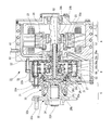
- FIG. 1 is an overall view of a cooling pipe that is insert-molded in an in-wheel motor drive device according to an embodiment of the present invention. It is a schematic plan view of the electric vehicle which has an in-wheel motor drive device. It is the figure seen from the electric vehicle back of FIG. It is a schematic longitudinal cross-sectional view of the deceleration part of embodiment of FIG. It is a schematic sectional drawing of the conventional in-wheel motor drive device.
- an electric vehicle 11 having an in-wheel motor drive device includes a chassis 12, a front wheel 13 as a steering wheel, a rear wheel 14 as a drive wheel, And an in-wheel motor drive device 21 that transmits a driving force to each of the rear wheels 14.
- the rear wheel 14 is housed inside a wheel housing 12 a of the chassis 12, and is fixed to the lower portion of the chassis 12 via a suspension device (suspension) 12 b.
- the suspension device 12b supports the rear wheel 14 by a suspension arm that extends to the left and right, and suppresses vibration of the chassis 12 by absorbing vibration received by the rear wheel 14 from the ground by a strut including a coil spring and a shock absorber. Furthermore, a stabilizer that suppresses the inclination of the vehicle body when turning is provided at the connecting portion of the left and right suspension arms.
- the suspension device 12b is an independent suspension type in which the left and right wheels can be moved up and down independently in order to improve the followability to the road surface unevenness and efficiently transmit the driving force of the driving wheels to the road surface. Is desirable.
- the electric vehicle 11 needs to be provided with a motor, a drive shaft, a differential gear mechanism, and the like on the chassis 12 by providing an in-wheel motor drive device 21 for driving the left and right rear wheels 14 inside the wheel housing 12a. This eliminates the need to secure a wide cabin space and control the rotation of the left and right drive wheels.
- the in-wheel motor drive device 21 is required to be smaller and lighter.
- the in-wheel motor drive device 21 includes a motor unit A that generates a driving force, a deceleration unit B that decelerates and outputs the rotation of the motor unit A, and an output from the deceleration unit B as driving wheels. 14 and a wheel hub bearing portion C for transmission to the motor vehicle 14 and is mounted in the wheel housing 12a of the electric vehicle 11 as shown in FIG.
- the housing 22 of the motor part A is a cast product of a light metal such as an aluminum alloy or a magnesium alloy.
- a pipe material is cast by insert molding, and a cooling water channel for internal cooling or an oil channel for lubricating oil is used.
- a pipe constituting the flow path is formed.
- the pipe includes a cooling pipe 61 through which a cooling liquid for the motor part A flows and a lubricating pipe 62 through which lubricating oil flows.
- the cooling pipe 61 is drawn out from the housing 22 so as to communicate with the outside of the motor part A.
- the cooling pipe 61 is arranged in the circumferential direction of the housing 22 of the motor part A, and is preferably arranged in a spiral shape as shown in FIG.
- the lubrication pipe 62 can also be used for cooling the motor part A.
- the lubrication pipe 62 is provided so as to circulate inside the apparatus without communicating with the outside of the apparatus.
- the lubrication pipe 62 is arranged in the radial direction and the axle direction.
- the lubricating oil in the lubricating pipe 62 is circulated by the built-in pump 51.
- the number of rotations of the built-in pump 51 is set to be the same as the number of rotations of the motor unit A when the motor unit A does not include the speed reduction unit B, but the motor unit A includes the speed reduction unit as in the embodiment. Is set to be different from the rotational speed of the motor part A.
- the motor unit A is fixedly coupled to the stator 23 fixed to the housing 22 of the motor unit A, the rotor 24 disposed at a position facing the inner side of the stator 23 with a radial gap therebetween, and the inner side of the rotor 24. And a motor-side rotating member 24b that rotates integrally with the rotor 24.
- the motor side rotation member 24b is rotatably supported by the rolling bearings 36a and 36b with respect to the housing 22 of the motor portion A.
- the motor side rotating member 24b is arranged from the motor part A to the speed reduction part B in order to transmit the driving force of the motor part A to the speed reduction part B.
- the motor-side rotating member 24b has a hollow structure, and the input shaft 25 of the speed reduction portion B is fitted and fixed.
- the input shaft 25 is provided with eccentric portions 25a and 25b.
- the two eccentric portions 25a and 25b are provided with a 180 ° phase change in order to cancel the centrifugal force due to the eccentric motion.
- the speed reduction part B is held at fixed positions on the curved plates 26a and 26b as revolving members that are rotatably held by the eccentric parts 25a and 25b and the speed reduction part housing 22b.
- the speed reduction part B is provided with a speed reduction part lubrication mechanism that supplies lubricating oil to the speed reduction part B.
- the wheel side rotation member 28 has a flange portion 28a and a shaft portion 28b. Holes for fixing the inner pins 31 are formed on the end face of the flange portion 28a at equal intervals on the circumference around the rotation axis of the wheel side rotation member 28. Further, the shaft portion 28 b is fitted and fixed to the hub wheel 32 and transmits the output of the speed reduction portion B to the wheel 14.
- the flange portion 28a of the wheel side rotation member 28 and the input shaft 25 are rotatably supported by a rolling bearing 36c.
- the curved plates 26a and 26b have a plurality of corrugated waves composed of trochoidal curves such as epitrochoids on the outer periphery, and a plurality of through holes 30a penetrating from one end face to the other end face.
- a plurality of through holes 30a are provided at equal intervals on the circumference centering on the rotation axis of the curved plates 26a, 26b, and receive inner pins 31 described later.
- the through hole 30b is provided at the center of the curved plates 26a and 26b and is fitted to the eccentric portions 25a and 25b.
- the curved plates 26a and 26b are supported by the rolling bearing 41 so as to be rotatable with respect to the eccentric portions 25a and 25b.
- the rolling bearing 41 is directly formed on the inner ring member having an inner raceway surface on the outer diameter surface of the eccentric portions 25a and 25b and the inner diameter surface of the through hole 30b of the curved plates 26a and 26b.
- a cylindrical roller bearing comprising an outer raceway surface, a plurality of cylindrical rollers 44 disposed between the inner raceway surface and the outer raceway surface, and a retainer (not shown) that holds the spacing between adjacent cylindrical rollers 44. .
- the outer pins 27 are provided at equal intervals on a circumferential track centering on the rotation axis of the input shaft 25.
- the curved plates 26a and 26b revolve, the curved waveform and the outer pin 27 engage with each other to cause the curved plates 26a and 26b to rotate.
- the outer pin 27 is rotatably supported with respect to the speed reduction unit housing 22b by a needle roller bearing. Thereby, the contact resistance between the curved plates 26a and 26b can be reduced.
- the counterweight 29 has a disc shape and has a through-hole that fits with the motor-side rotation member 25 at a position off the center, in order to cancel out the unbalanced inertia couple caused by the rotation of the curved plates 26a and 26b. It is arranged at a position adjacent to each eccentric part 25a, 25b with a 180 ° phase change from the eccentric part.
- the motion conversion mechanism includes a plurality of inner pins 31 held by the wheel-side rotating member 28 and through holes 30a provided in the curved plates 26a and 26b.
- the inner pins 31 are provided at equal intervals on a circumferential track centering on the rotational axis of the wheel side rotation member 28, and one axial end thereof is fixed to the wheel side rotation member 28.
- needle roller bearings are provided at positions where they contact the inner wall surfaces of the through holes 30a of the curved plates 26a and 26b.
- the through hole 30a is provided at a position corresponding to each of the plurality of inner pins 31, and the inner diameter dimension of the through hole 30a indicates the outer diameter dimension of the inner pin 31 ("maximum outer diameter including needle roller bearing"). It is set larger by a predetermined amount than the same).
- the speed reduction unit lubrication mechanism supplies lubricating oil to the speed reduction unit B, and includes a lubricating oil passage 52, a lubricating oil supply port 53, a lubricating oil discharge port 54, a lubricating oil storage unit 55, and a built-in pump 51.
- the lubricating oil passage 52 extends along the axial direction inside the input shaft 25.
- the lubricating oil supply port 53 is provided in the eccentric portions 25a and 25b.
- At least one position of the speed reduction part housing 22b at the position of the speed reduction part B is provided with a lubricating oil discharge port 54 for discharging the lubricating oil inside the speed reduction part B.
- a lubricating pipe 62 that connects the lubricating oil discharge port 54 and the lubricating oil passage 52 is provided inside the housing 22 of the motor part A. Then, the lubricating oil discharged from the lubricating oil discharge port 54 returns to the lubricating oil passage 52 via the lubricating pipe 62.
- the wheel hub bearing portion C includes a hub wheel 32 to which the wheel 14 fixedly connected to the wheel-side rotating member 28 is attached, and a fixed wheel 33 that rotatably holds the hub wheel 32 with respect to the case 22b of the speed reduction unit B. .
- the hub wheel 32 has a cylindrical hollow portion 32a and a flange portion 32b.
- the wheel 14 is fixedly connected to the flange portion 32b by a bolt 32c.
- a spline and a male screw are formed on the outer diameter surface of the shaft portion 28b of the wheel side rotation member 28.
- a spline hole is formed in the inner diameter surface of the hollow portion 32 a of the hub wheel 32. Then, the wheel-side rotating member 28 is screwed to the inner diameter surface of the hub wheel 32, and both ends are fastened by fastening the tip with a nut 32d.
- the hub wheel 32 has a wheel mounting flange 32b integrally formed on the outer surface of the hollow portion 32a.
- An outer raceway surface is integrally formed on the outer diameter surface of the hollow portion 32a on the outer side of the vehicle, and an inner ring 32e having an inner raceway surface on the outer surface is fitted to the outer diameter surface of the hollow portion 32a on the inner side of the vehicle. is doing.
- the fixed ring 33 has an outer raceway surface and an inner raceway surface facing the outer raceway surface and the inner raceway surface of the hub ring 32 on the inner peripheral surface, and a fixing flange 33a on the outer peripheral surface.
- a double-row ball 34 is accommodated between the outer raceway surface and the inner raceway surface of the hub wheel 32 and the fixed ring 33 facing each other.
- the fixing flange 33 a of the fixed wheel 33 and the speed reduction unit housing 22 b are fastened by a bolt 71. Further, the speed reduction unit housing 22 b and the housing 22 of the motor unit A are fastened by bolts 72.
- a double-row ball 34 is accommodated between the outer raceway surface and the inner raceway surface of the hub wheel 32 and the fixed ring 33 facing each other.
- the motor unit A receives, for example, an electromagnetic force generated by supplying an alternating current to the coil of the stator 23, and the rotor 24 composed of a permanent magnet or a magnetic material rotates.
- the curved plates 26 a and 26 b revolve around the rotation axis of the input shaft 25.
- the outer pin 27 engages with the curved waveform of the curved plates 26 a and 26 b to cause the curved plates 26 a and 26 b to rotate in the direction opposite to the rotation of the input shaft 25.
- the inner pin 31 inserted through the through hole 30a comes into contact with the inner wall surface of the through hole 30a as the curved plates 26a and 26b rotate.
- the revolving motion of the curved plates 26 a and 26 b is not transmitted to the inner pin 31, but only the rotational motion of the curved plates 26 a and 26 b is transmitted to the wheel hub bearing portion C via the wheel-side rotating member 28.
- the reduction ratio of the reduction part B having the above-described configuration is calculated as (ZA ⁇ ZB) / ZB, where ZA is the number of outer pins 27 and ZB is the number of waveforms of the curved plates 26a and 26b.
- the in-wheel motor drive device 21 having a compact and high reduction ratio can be obtained. Further, by providing the needle roller bearings on the outer pin 27 and the inner pin 31, the frictional resistance between the curved plates 26a and 26b is reduced, so that the transmission efficiency of the speed reducing portion B is improved.
- the unsprung weight can be suppressed.
- the electric vehicle 11 having excellent running stability can be obtained.
- the present invention is not limited to this, and the lubricating oil supply port 53 can be provided at any position of the input shaft 25.
- two curved plates 26a and 26b of the deceleration unit B are provided with a 180 ° phase change.
- the number of the curved plates can be arbitrarily set. When three are provided, it is preferable to change the phase by 120 °.
- the motion conversion mechanism in the said embodiment showed the example comprised by the inner pin 31 fixed to the wheel side rotation member 28, and the through-hole 30a provided in the curve boards 26a and 26b, Without being limited to the above, it is possible to adopt an arbitrary configuration capable of transmitting the rotation of the speed reduction unit B to the wheel hub 32.
- it may be a motion conversion mechanism composed of an inner pin fixed to a curved plate and a hole formed in the wheel side rotation member.
- a radial gap motor is adopted as the motor part A
- the present invention is not limited to this, and a motor having an arbitrary configuration can be applied.
- it may be an axial gap motor including a stator fixed to the housing and a rotor disposed at a position facing the inner side of the stator with a gap in the axial direction.
- the example of the in-wheel motor drive device 21 in which the cycloid reduction mechanism is adopted for the reduction part B is shown, but the present invention is not limited to this, and any reduction mechanism can be adopted.
- a planetary gear reduction mechanism, a parallel shaft gear reduction mechanism, or the like is applicable.
- this invention is applicable also in the in-wheel motor unit (motor direct drive) without a reduction gear.
- the electric vehicle 11 shown in FIG. 3 has shown the example which used the rear wheel 14 as the driving wheel, it is not restricted to this,
- the front wheel 13 may be used as a driving wheel and may be a four-wheel driving vehicle.
- “electric vehicle” is a concept including all vehicles that obtain driving force from electric power, and should be understood as including, for example, a hybrid vehicle.
Abstract
Provided is a device for driving an in-wheel motor, which is not broken by flying stones or the like and has easy-to-process flow passes for cooling purposes and for an inner lubricant oils. A device for driving an in-wheel motor, which comprises a motor part (A) which can generate a driving force for a wheel and is arranged in the wheel, wherein a pipe (61, 62) which constitutes a flow pass as a passage for cooling water for cooling the inside or as an oil passage for a lubricant oil is formed in a housing (22) in the motor part (A) by insert molding, the housing (22) is composed of a cast product of a light metal such as an aluminum alloy and a magnesium alloy, and the pipe (61, 62) can be formed by casting a pipe material that can be formed into the pipe during the casting.
Description
この発明は、インホイールモータ駆動装置、特に装置の冷却及び内部潤滑油の流路に関するものである。
The present invention relates to an in-wheel motor drive device, and more particularly to cooling of the device and a flow path of internal lubricating oil.
従来のインホイールモータ駆動装置101は、例えば、特開2009-174593号公報(特許文献1)に記載されている。
A conventional in-wheel motor drive device 101 is described in, for example, Japanese Patent Application Laid-Open No. 2009-174593 (Patent Document 1).
図6に示すインホイールモータ駆動装置101は、モータ側回転部材106を回転駆動するモータ部103と、前記モータ側回転部材106の回転を減速して車輪側回転部材108に伝達する減速部105と、前記車輪側回転部材108に固定連結される車輪ハブ109を有する車輪ハブ軸受部104とを備えている。
An in-wheel motor drive device 101 shown in FIG. 6 includes a motor unit 103 that rotationally drives the motor-side rotating member 106, a speed reducing unit 105 that decelerates the rotation of the motor-side rotating member 106 and transmits the rotation to the wheel-side rotating member 108. And a wheel hub bearing portion 104 having a wheel hub 109 fixedly connected to the wheel side rotating member 108.
ところで、前記インホイールモータ駆動装置101には、通常、内部冷却用の冷却水路107及び潤滑油用の油路110が必要である。
By the way, the in-wheel motor drive device 101 normally requires a cooling water passage 107 for internal cooling and an oil passage 110 for lubricating oil.
従来、内部冷却用の冷却水路107及び潤滑油用の油路110は、モータ部103のハウジング102を後加工することにより形成しているが、冷却水路107や油路110の形成には、加工工数が掛かり、冷却水路107や油路110の流路が細い場合には、加工が困難である。
Conventionally, the cooling water passage 107 for internal cooling and the oil passage 110 for lubricating oil are formed by post-processing the housing 102 of the motor unit 103. Processing is difficult when man-hours are required and the cooling water passage 107 and the oil passage 110 are thin.
また、モータ部103のハウジング102の外部の外周面に、流路を形成した場合には、飛び石、接触等で、流路を形成する配管が破損して、液体が流出する恐れがある。
In addition, when a flow path is formed on the outer peripheral surface of the outside of the housing 102 of the motor unit 103, the pipe forming the flow path may be damaged by a stepping stone, contact, etc., and the liquid may flow out.
そこで、この発明は、飛び石等による破損の心配がなく、加工も容易な冷却及び内部潤滑油の流路構造を提供しようとするものである。
Therefore, the present invention is intended to provide a cooling and internal lubricating oil flow path structure that is easy to process without worrying about breakage due to stepping stones and the like.
前記の課題を解決するために、この発明は、車輪の駆動力を発生するモータ部を前記車輪内に有するインホイールモータ駆動装置において、内部冷却用の冷却水路又は潤滑油用の油路の流路を構成する配管を、前記モータ部のハウジングにインサート成形により形成したものである。
In order to solve the above-described problems, the present invention provides an in-wheel motor drive device having a motor unit for generating a wheel driving force in the wheel, the flow of a cooling water channel for internal cooling or an oil channel for lubricating oil. A pipe constituting the path is formed by insert molding in the housing of the motor unit.
前記ハウジングは、アルミニウム合金、マグネシウム合金等の軽金属の鋳造品からなり、前記配管は、鋳造の際に、配管となるパイプ材を鋳込んで形成することができる。
The housing is made of a cast product of a light metal such as an aluminum alloy or a magnesium alloy, and the pipe can be formed by casting a pipe material that becomes a pipe at the time of casting.
前記配管は、モータ部の冷却用の液体が流れる冷却用配管として使用することができる。
The pipe can be used as a cooling pipe through which a cooling liquid for the motor section flows.
冷却用配管は、モータ部の外部に連通させることができる。
¡The cooling pipe can communicate with the outside of the motor unit.
冷却用配管は、モータ部のハウジングの円周方向に1周又は螺旋状に配置することが好ましい。
It is preferable to arrange the cooling pipe in one or a spiral shape in the circumferential direction of the housing of the motor unit.
前記配管は、潤滑油が流れる潤滑用配管としても使用することができる。
The piping can also be used as a lubricating piping through which lubricating oil flows.
前記潤滑用配管は、モータ部の冷却用としても使用することができる。
The lubrication pipe can also be used for cooling the motor unit.
前記潤滑用配管は、装置外部に連通させずに、装置内部で循環するように設ける。
The lubrication pipe is provided so as to circulate inside the apparatus without communicating with the outside of the apparatus.
前記潤滑用配管は、径方向及び車軸方向に配置する。
¡The lubrication pipes are arranged in the radial direction and the axle direction.
前記冷却用配管と潤滑用配管は、片方のみを設けてもよいが、両方を設けることが好ましい。
Only one of the cooling pipe and the lubricating pipe may be provided, but it is preferable to provide both.
前記潤滑用配管内の潤滑油を循環させる内蔵ポンプが装置内に設置することが好ましい。
It is preferable that a built-in pump for circulating the lubricating oil in the lubrication pipe is installed in the apparatus.
内蔵ポンプの回転数が、モータ部の減速部を備えないものにおいては、モータ部の回転数と同一で、モータ部の減速部を備えるものにおいては、モータ部の回転数と異なるように設定される。
The number of rotations of the built-in pump is set to be the same as the number of rotations of the motor unit when the reduction unit of the motor unit is not provided, and different from the number of rotations of the motor unit when the reduction number of the motor unit is provided. The
この発明は、以上のように、内部冷却用の冷却水路又は潤滑油用の油路の流路を構成する配管を、前記モータ部のハウジングにインサート成形により形成しているので、飛び石等の破損の心配がなく、細い流路のものも簡単に形成できる。
In the present invention, as described above, the pipes constituting the flow path of the cooling water passage for internal cooling or the oil passage for lubricating oil are formed in the housing of the motor portion by insert molding, so that breakage of stepping stones, etc. It is possible to easily form a thin channel.
以下、この発明の実施の形態を添付図面に基づいて説明する。
この発明の一実施形態に係るインホイールモータ駆動装置を備えた電気自動車11は、図3に示すように、シャーシ12と、操舵輪としての前輪13と、駆動輪としての後輪14と、左右の後輪14それぞれに駆動力を伝達するインホイールモータ駆動装置21とを備える。後輪14は、図4に示すように、シャーシ12のホイールハウジング12aの内部に収容され、懸架装置(サスペンション)12bを介してシャーシ12の下部に固定されている。 Embodiments of the present invention will be described below with reference to the accompanying drawings.
As shown in FIG. 3, anelectric vehicle 11 having an in-wheel motor drive device according to an embodiment of the present invention includes a chassis 12, a front wheel 13 as a steering wheel, a rear wheel 14 as a drive wheel, And an in-wheel motor drive device 21 that transmits a driving force to each of the rear wheels 14. As shown in FIG. 4, the rear wheel 14 is housed inside a wheel housing 12 a of the chassis 12, and is fixed to the lower portion of the chassis 12 via a suspension device (suspension) 12 b.
この発明の一実施形態に係るインホイールモータ駆動装置を備えた電気自動車11は、図3に示すように、シャーシ12と、操舵輪としての前輪13と、駆動輪としての後輪14と、左右の後輪14それぞれに駆動力を伝達するインホイールモータ駆動装置21とを備える。後輪14は、図4に示すように、シャーシ12のホイールハウジング12aの内部に収容され、懸架装置(サスペンション)12bを介してシャーシ12の下部に固定されている。 Embodiments of the present invention will be described below with reference to the accompanying drawings.
As shown in FIG. 3, an
懸架装置12bは、左右に伸びるサスペンションアームによって後輪14を支持すると共に、コイルスプリングとショックアブソーバとを含むストラットによって、後輪14が地面から受ける振動を吸収してシャーシ12の振動を抑制する。さらに、左右のサスペンションアームの連結部分には、旋回時等に車体の傾きを抑制するスタビライザーが設けられる。なお、懸架装置12bは、路面の凹凸に対する追従性を向上し、駆動輪の駆動力を効率良く路面に伝達するために、左右の車輪を独立して上下させることができる独立懸架式とするのが望ましい。
The suspension device 12b supports the rear wheel 14 by a suspension arm that extends to the left and right, and suppresses vibration of the chassis 12 by absorbing vibration received by the rear wheel 14 from the ground by a strut including a coil spring and a shock absorber. Furthermore, a stabilizer that suppresses the inclination of the vehicle body when turning is provided at the connecting portion of the left and right suspension arms. The suspension device 12b is an independent suspension type in which the left and right wheels can be moved up and down independently in order to improve the followability to the road surface unevenness and efficiently transmit the driving force of the driving wheels to the road surface. Is desirable.
この電気自動車11は、ホイールハウジング12a内部に、左右の後輪14それぞれを駆動するインホイールモータ駆動装置21を設けることによって、シャーシ12上にモータ、ドライブシャフト、およびデファレンシャルギヤ機構等を設ける必要がなくなるので、客室スペースを広く確保でき、かつ、左右の駆動輪の回転をそれぞれ制御することができるという利点を備えている。
The electric vehicle 11 needs to be provided with a motor, a drive shaft, a differential gear mechanism, and the like on the chassis 12 by providing an in-wheel motor drive device 21 for driving the left and right rear wheels 14 inside the wheel housing 12a. This eliminates the need to secure a wide cabin space and control the rotation of the left and right drive wheels.
一方、この電気自動車11の走行安定性を向上するために、ばね下重量を抑える必要がある。また、さらに広い客室スペースを確保するために、インホイールモータ駆動装置21の小型・軽量化が求められる。
On the other hand, in order to improve the running stability of the electric vehicle 11, it is necessary to suppress the unsprung weight. Further, in order to secure a wider cabin space, the in-wheel motor drive device 21 is required to be smaller and lighter.
インホイールモータ駆動装置21は、図1に示すように、駆動力を発生させるモータ部Aと、モータ部Aの回転を減速して出力する減速部Bと、減速部Bからの出力を駆動輪14に伝える車輪ハブ軸受部Cとを備え、図4に示すように電気自動車11のホイールハウジング12a内に取り付けられる。
As shown in FIG. 1, the in-wheel motor drive device 21 includes a motor unit A that generates a driving force, a deceleration unit B that decelerates and outputs the rotation of the motor unit A, and an output from the deceleration unit B as driving wheels. 14 and a wheel hub bearing portion C for transmission to the motor vehicle 14 and is mounted in the wheel housing 12a of the electric vehicle 11 as shown in FIG.
前記モータ部Aのハウジング22は、アルミニウム合金、マグネシウム合金等の軽金属の鋳造品であり、鋳造の際に、インサート成形によりパイプ材を鋳込み、内部冷却用の冷却水路又は潤滑油用の油路の流路を構成する配管を形成している。
The housing 22 of the motor part A is a cast product of a light metal such as an aluminum alloy or a magnesium alloy. In casting, a pipe material is cast by insert molding, and a cooling water channel for internal cooling or an oil channel for lubricating oil is used. A pipe constituting the flow path is formed.
前記配管は、モータ部Aの冷却用の液体が流れる冷却用配管61と、潤滑油が流れる潤滑用配管62とからなる。
The pipe includes a cooling pipe 61 through which a cooling liquid for the motor part A flows and a lubricating pipe 62 through which lubricating oil flows.
冷却用配管61は、モータ部Aの外部に連通するように、ハウジング22から外部に引き出されている。
The cooling pipe 61 is drawn out from the housing 22 so as to communicate with the outside of the motor part A.
冷却用配管61は、モータ部Aのハウジング22の円周方向に配置され、一周よりも、図2に示すように、螺旋状に配置することが好ましい。
The cooling pipe 61 is arranged in the circumferential direction of the housing 22 of the motor part A, and is preferably arranged in a spiral shape as shown in FIG.
前記潤滑用配管62は、モータ部Aの冷却用として使用することもできる。
The lubrication pipe 62 can also be used for cooling the motor part A.
前記潤滑用配管62は、装置外部に連通させずに、装置内部で循環するように設けている。
The lubrication pipe 62 is provided so as to circulate inside the apparatus without communicating with the outside of the apparatus.
前記潤滑用配管62は、径方向及び車軸方向に配置されている。
The lubrication pipe 62 is arranged in the radial direction and the axle direction.
前記潤滑用配管62内の潤滑油は、内蔵ポンプ51によって循環している。
The lubricating oil in the lubricating pipe 62 is circulated by the built-in pump 51.
内蔵ポンプ51の回転数は、モータ部Aの減速部Bを備えないものにおいては、モータ部Aの回転数と同一に設定されるが、実施形態のようにモータ部Aの減速部を備えるものにおいては、モータ部Aの回転数と異なるように設定される。
The number of rotations of the built-in pump 51 is set to be the same as the number of rotations of the motor unit A when the motor unit A does not include the speed reduction unit B, but the motor unit A includes the speed reduction unit as in the embodiment. Is set to be different from the rotational speed of the motor part A.
モータ部Aは、モータ部Aのハウジング22に固定されるステータ23と、ステータ23の内側に径方向の隙間を空けて対向する位置に配置されるロータ24と、ロータ24の内側に固定連結されてロータ24と一体回転するモータ側回転部材24bとを備えるラジアルギャップモータである。モータ側回転部材24bは、モータ部Aのハウジング22に対して転がり軸受36a、36bによって回転自在に支持されている。
The motor unit A is fixedly coupled to the stator 23 fixed to the housing 22 of the motor unit A, the rotor 24 disposed at a position facing the inner side of the stator 23 with a radial gap therebetween, and the inner side of the rotor 24. And a motor-side rotating member 24b that rotates integrally with the rotor 24. The motor side rotation member 24b is rotatably supported by the rolling bearings 36a and 36b with respect to the housing 22 of the motor portion A.
モータ側回転部材24bは、モータ部Aの駆動力を減速部Bに伝達するためにモータ部Aから減速部Bにかけて配置されている。モータ側回転部材24bは、中空構造で、減速部Bの入力軸25が嵌合固定され、入力軸25には偏心部25a、25bが設けられている。2つの偏心部25a、25bは、偏心運動による遠心力を互いに打ち消し合うために、180°位相を変えて設けられている。
The motor side rotating member 24b is arranged from the motor part A to the speed reduction part B in order to transmit the driving force of the motor part A to the speed reduction part B. The motor-side rotating member 24b has a hollow structure, and the input shaft 25 of the speed reduction portion B is fitted and fixed. The input shaft 25 is provided with eccentric portions 25a and 25b. The two eccentric portions 25a and 25b are provided with a 180 ° phase change in order to cancel the centrifugal force due to the eccentric motion.
減速部Bは、偏心部25a、25bに回転自在に保持される公転部材としての曲線板26a、26bと、減速部ハウジング22b上の固定位置に保持され、曲線板26a、26bの外周部に係合する外周係合部材としての複数の外ピン27と、曲線板26a、26bの自転運動を車輪側回転部材28に伝達する運動変換機構と、偏心部25a、25bに隣接する位置にカウンタウェイト29とを備える。また、減速部Bには、減速部Bに潤滑油を供給する減速部潤滑機構が設けられている。
The speed reduction part B is held at fixed positions on the curved plates 26a and 26b as revolving members that are rotatably held by the eccentric parts 25a and 25b and the speed reduction part housing 22b. A plurality of outer pins 27 as outer peripheral engagement members to be combined, a motion conversion mechanism for transmitting the rotational motion of the curved plates 26a and 26b to the wheel side rotation member 28, and a counterweight 29 at a position adjacent to the eccentric portions 25a and 25b. With. In addition, the speed reduction part B is provided with a speed reduction part lubrication mechanism that supplies lubricating oil to the speed reduction part B.
車輪側回転部材28は、フランジ部28aと軸部28bとを有する。フランジ部28aの端面には、車輪側回転部材28の回転軸心を中心とする円周上の等間隔に内ピン31を固定する穴が形成されている。また、軸部28bはハブ輪32に嵌合固定され、減速部Bの出力を車輪14に伝達する。車輪側回転部材28のフランジ部28aと入力軸25とは、転がり軸受36cによって回転自在に支持されている。
The wheel side rotation member 28 has a flange portion 28a and a shaft portion 28b. Holes for fixing the inner pins 31 are formed on the end face of the flange portion 28a at equal intervals on the circumference around the rotation axis of the wheel side rotation member 28. Further, the shaft portion 28 b is fitted and fixed to the hub wheel 32 and transmits the output of the speed reduction portion B to the wheel 14. The flange portion 28a of the wheel side rotation member 28 and the input shaft 25 are rotatably supported by a rolling bearing 36c.
曲線板26a、26bは、図5に示すように、外周部にエピトロコイド等のトロコイド系曲線で構成される複数の波形を有し、一方側端面から他方側端面に貫通する複数の貫通孔30aを有する。貫通孔30aは、曲線板26a、26bの自転軸心を中心とする円周上に等間隔に複数個設けられており、後述する内ピン31を受入れる。また、貫通孔30bは、曲線板26a、26bの中心に設けられており、偏心部25a、25bに嵌合する。
As shown in FIG. 5, the curved plates 26a and 26b have a plurality of corrugated waves composed of trochoidal curves such as epitrochoids on the outer periphery, and a plurality of through holes 30a penetrating from one end face to the other end face. Have A plurality of through holes 30a are provided at equal intervals on the circumference centering on the rotation axis of the curved plates 26a, 26b, and receive inner pins 31 described later. Further, the through hole 30b is provided at the center of the curved plates 26a and 26b and is fitted to the eccentric portions 25a and 25b.
曲線板26a、26bは、転がり軸受41によって偏心部25a、25bに対して回転自在に支持されている。この転がり軸受41は、偏心部25a、25bの外径面に嵌合し、その外径面に内側軌道面を有する内輪部材と、曲線板26a、26bの貫通孔30bの内径面に直接形成された外側軌道面と、内側軌道面および外側軌道面の間に配置される複数の円筒ころ44と、隣接する円筒ころ44の間隔を保持する保持器(図示省略)とを備える円筒ころ軸受である。
The curved plates 26a and 26b are supported by the rolling bearing 41 so as to be rotatable with respect to the eccentric portions 25a and 25b. The rolling bearing 41 is directly formed on the inner ring member having an inner raceway surface on the outer diameter surface of the eccentric portions 25a and 25b and the inner diameter surface of the through hole 30b of the curved plates 26a and 26b. A cylindrical roller bearing comprising an outer raceway surface, a plurality of cylindrical rollers 44 disposed between the inner raceway surface and the outer raceway surface, and a retainer (not shown) that holds the spacing between adjacent cylindrical rollers 44. .
外ピン27は、入力軸25の回転軸心を中心とする円周軌道上に等間隔に設けられる。曲線板26a、26bが公転運動すると、曲線形状の波形と外ピン27とが係合して、曲線板26a、26bに自転運動を生じさせる。ここで、外ピン27は、針状ころ軸受によって減速部ハウジング22bに対して回転自在に支持されている。これにより、曲線板26a、26bとの間の接触抵抗を低減することができる。
The outer pins 27 are provided at equal intervals on a circumferential track centering on the rotation axis of the input shaft 25. When the curved plates 26a and 26b revolve, the curved waveform and the outer pin 27 engage with each other to cause the curved plates 26a and 26b to rotate. Here, the outer pin 27 is rotatably supported with respect to the speed reduction unit housing 22b by a needle roller bearing. Thereby, the contact resistance between the curved plates 26a and 26b can be reduced.
カウンタウェイト29は、円板状で、中心から外れた位置にモータ側回転部材25と嵌合する貫通孔を有し、曲線板26a、26bの回転によって生じる不釣合い慣性偶力を打ち消すために、各偏心部25a、25bに隣接する位置に偏心部と180°位相を変えて配置される。
The counterweight 29 has a disc shape and has a through-hole that fits with the motor-side rotation member 25 at a position off the center, in order to cancel out the unbalanced inertia couple caused by the rotation of the curved plates 26a and 26b. It is arranged at a position adjacent to each eccentric part 25a, 25b with a 180 ° phase change from the eccentric part.
運動変換機構は、車輪側回転部材28に保持された複数の内ピン31と、曲線板26a、26bに設けられた貫通孔30aとで構成される。内ピン31は、車輪側回転部材28の回転軸心を中心とする円周軌道上に等間隔に設けられており、その軸方向一方側端部が車輪側回転部材28に固定されている。また、曲線板26a、26bとの摩擦抵抗を低減するために、曲線板26a、26bの貫通孔30aの内壁面に当接する位置に針状ころ軸受が設けられている。
The motion conversion mechanism includes a plurality of inner pins 31 held by the wheel-side rotating member 28 and through holes 30a provided in the curved plates 26a and 26b. The inner pins 31 are provided at equal intervals on a circumferential track centering on the rotational axis of the wheel side rotation member 28, and one axial end thereof is fixed to the wheel side rotation member 28. Further, in order to reduce the frictional resistance with the curved plates 26a and 26b, needle roller bearings are provided at positions where they contact the inner wall surfaces of the through holes 30a of the curved plates 26a and 26b.
貫通孔30aは、複数の内ピン31それぞれに対応する位置に設けられ、貫通孔30aの内径寸法は、内ピン31の外径寸法(「針状ころ軸受を含む最大外径」を指す。以下同じ。)より所定分大きく設定されている。
The through hole 30a is provided at a position corresponding to each of the plurality of inner pins 31, and the inner diameter dimension of the through hole 30a indicates the outer diameter dimension of the inner pin 31 ("maximum outer diameter including needle roller bearing"). It is set larger by a predetermined amount than the same).
減速部潤滑機構は、減速部Bに潤滑油を供給するものであって、潤滑油路52と、潤滑油給油口53と、潤滑油排出口54と、潤滑油貯留部55と、内蔵ポンプ51とを備える。
The speed reduction unit lubrication mechanism supplies lubricating oil to the speed reduction unit B, and includes a lubricating oil passage 52, a lubricating oil supply port 53, a lubricating oil discharge port 54, a lubricating oil storage unit 55, and a built-in pump 51. With.
潤滑油路52は、入力軸25の内部を軸線方向に沿って延びている。また、潤滑油供給口53は、偏心部25a、25bに設けられている。
The lubricating oil passage 52 extends along the axial direction inside the input shaft 25. The lubricating oil supply port 53 is provided in the eccentric portions 25a and 25b.
また、減速部Bの位置における減速部ハウジング22bの少なくとも1箇所には、減速部Bの内部の潤滑油を排出する潤滑油排出口54が設けられている。また、潤滑油排出口54と潤滑油路52とを接続する潤滑用配管62がモータ部Aのハウジング22の内部に設けられている。そして、潤滑油排出口54から排出された潤滑油は、潤滑用配管62を経由して潤滑油路52に還流する。
Further, at least one position of the speed reduction part housing 22b at the position of the speed reduction part B is provided with a lubricating oil discharge port 54 for discharging the lubricating oil inside the speed reduction part B. Further, a lubricating pipe 62 that connects the lubricating oil discharge port 54 and the lubricating oil passage 52 is provided inside the housing 22 of the motor part A. Then, the lubricating oil discharged from the lubricating oil discharge port 54 returns to the lubricating oil passage 52 via the lubricating pipe 62.
車輪ハブ軸受部Cは、車輪側回転部材28に固定連結された車輪14を取付けるハブ輪32と、ハブ輪32を減速部Bのケース22bに対して回転自在に保持する固定輪33とを備える。ハブ輪32は、円筒形状の中空部32aとフランジ部32bとを有する。フランジ部32bにはボルト32cによって車輪14が固定連結される。また、車輪側回転部材28の軸部28bの外径面にはスプラインおよび雄ねじが形成されている。また、ハブ輪32の中空部32aの内径面にはスプライン穴が形成されている。そして、ハブ輪32の内径面に車輪側回転部材28を螺合し、先端をナット32dでとめることによって、両者を締結している。
The wheel hub bearing portion C includes a hub wheel 32 to which the wheel 14 fixedly connected to the wheel-side rotating member 28 is attached, and a fixed wheel 33 that rotatably holds the hub wheel 32 with respect to the case 22b of the speed reduction unit B. . The hub wheel 32 has a cylindrical hollow portion 32a and a flange portion 32b. The wheel 14 is fixedly connected to the flange portion 32b by a bolt 32c. A spline and a male screw are formed on the outer diameter surface of the shaft portion 28b of the wheel side rotation member 28. A spline hole is formed in the inner diameter surface of the hollow portion 32 a of the hub wheel 32. Then, the wheel-side rotating member 28 is screwed to the inner diameter surface of the hub wheel 32, and both ends are fastened by fastening the tip with a nut 32d.
ハブ輪32は、中空部32aの外面に車輪取付けフランジ32bが一体形成されている。中空部32aの車両アウター側の外径面には、アウター側軌道面が一体に形成され、中空部32aの車両インナー側の外径面に、外面にインナー側軌道面を有する内輪32eを嵌合している。
The hub wheel 32 has a wheel mounting flange 32b integrally formed on the outer surface of the hollow portion 32a. An outer raceway surface is integrally formed on the outer diameter surface of the hollow portion 32a on the outer side of the vehicle, and an inner ring 32e having an inner raceway surface on the outer surface is fitted to the outer diameter surface of the hollow portion 32a on the inner side of the vehicle. is doing.
固定輪33は、内周面に、ハブ輪32のアウター側軌道面とインナー側軌道面に対向するアウター側軌道面とインナー側軌道面を有し、外周面に、固定用フランジ33aを有する。
The fixed ring 33 has an outer raceway surface and an inner raceway surface facing the outer raceway surface and the inner raceway surface of the hub ring 32 on the inner peripheral surface, and a fixing flange 33a on the outer peripheral surface.
ハブ輪32と固定輪33の対向するアウター側軌道面とインナー側軌道面間には、複列の玉34が収容されている。
A double-row ball 34 is accommodated between the outer raceway surface and the inner raceway surface of the hub wheel 32 and the fixed ring 33 facing each other.
固定輪33の固定用フランジ33aと減速部ハウジング22bとは、ボルト71によって締結されている。また、減速部ハウジング22bとモータ部Aのハウジング22とは、ボルト72によって締結されている。
The fixing flange 33 a of the fixed wheel 33 and the speed reduction unit housing 22 b are fastened by a bolt 71. Further, the speed reduction unit housing 22 b and the housing 22 of the motor unit A are fastened by bolts 72.
ハブ輪32と固定輪33の対向するアウター側軌道面とインナー側軌道面間には、複列の玉34が収容されている。
A double-row ball 34 is accommodated between the outer raceway surface and the inner raceway surface of the hub wheel 32 and the fixed ring 33 facing each other.
以下、インホイールモータ駆動装置21の作動原理について説明する。
モータ部Aは、例えば、ステータ23のコイルに交流電流を供給することによって生じる電磁力を受けて、永久磁石または磁性体によって構成されるロータ24が回転する。これにより、ロータ24にモータ側回転部材24bを介して接続された入力軸25が回転すると、曲線板26a、26bは入力軸25の回転軸心を中心として公転運動する。このとき、外ピン27が、曲線板26a、26bの曲線形状の波形と係合して、曲線板26a、26bを入力軸25の回転とは逆向きに自転運動させる。 Hereinafter, the operation principle of the in-wheelmotor drive device 21 will be described.
The motor unit A receives, for example, an electromagnetic force generated by supplying an alternating current to the coil of thestator 23, and the rotor 24 composed of a permanent magnet or a magnetic material rotates. As a result, when the input shaft 25 connected to the rotor 24 via the motor-side rotating member 24 b rotates, the curved plates 26 a and 26 b revolve around the rotation axis of the input shaft 25. At this time, the outer pin 27 engages with the curved waveform of the curved plates 26 a and 26 b to cause the curved plates 26 a and 26 b to rotate in the direction opposite to the rotation of the input shaft 25.
モータ部Aは、例えば、ステータ23のコイルに交流電流を供給することによって生じる電磁力を受けて、永久磁石または磁性体によって構成されるロータ24が回転する。これにより、ロータ24にモータ側回転部材24bを介して接続された入力軸25が回転すると、曲線板26a、26bは入力軸25の回転軸心を中心として公転運動する。このとき、外ピン27が、曲線板26a、26bの曲線形状の波形と係合して、曲線板26a、26bを入力軸25の回転とは逆向きに自転運動させる。 Hereinafter, the operation principle of the in-wheel
The motor unit A receives, for example, an electromagnetic force generated by supplying an alternating current to the coil of the
貫通孔30aに挿通する内ピン31は、曲線板26a、26bの自転運動に伴って貫通孔30aの内壁面と当接する。これにより、曲線板26a、26bの公転運動が内ピン31に伝わらず、曲線板26a、26bの自転運動のみが車輪側回転部材28を介して車輪ハブ軸受部Cに伝達される。
The inner pin 31 inserted through the through hole 30a comes into contact with the inner wall surface of the through hole 30a as the curved plates 26a and 26b rotate. As a result, the revolving motion of the curved plates 26 a and 26 b is not transmitted to the inner pin 31, but only the rotational motion of the curved plates 26 a and 26 b is transmitted to the wheel hub bearing portion C via the wheel-side rotating member 28.
このとき、入力軸25の回転が減速部Bによって減速されて車輪側回転部材28に伝達されるので、低トルク、高回転型のモータ部Aを採用した場合でも、駆動輪14に必要なトルクを伝達することが可能となる。
At this time, since the rotation of the input shaft 25 is decelerated by the deceleration unit B and transmitted to the wheel side rotation member 28, even when the low torque, high rotation type motor unit A is employed, the torque required for the drive wheels 14 Can be transmitted.
なお、前記構成の減速部Bの減速比は、外ピン27の数をZA、曲線板26a、26bの波形の数をZBとすると、(ZA-ZB)/ZBで算出される。図5に示す実施形態では、ZA=12、ZB=11であるので、減速比は1/11と、非常に大きな減速比を得ることができる。
Note that the reduction ratio of the reduction part B having the above-described configuration is calculated as (ZA−ZB) / ZB, where ZA is the number of outer pins 27 and ZB is the number of waveforms of the curved plates 26a and 26b. In the embodiment shown in FIG. 5, since ZA = 12, ZB = 11, the reduction ratio is 1/11, and a very large reduction ratio can be obtained.
このように、多段構成とすることなく大きな減速比を得ることができる減速部Bを採用することにより、コンパクトで高減速比のインホイールモータ駆動装置21を得ることができる。また、外ピン27および内ピン31に針状ころ軸受を設けたことにより、曲線板26a、26bとの間の摩擦抵抗が低減されるので、減速部Bの伝達効率が向上する。
In this way, by adopting the reduction part B that can obtain a large reduction ratio without using a multistage configuration, the in-wheel motor drive device 21 having a compact and high reduction ratio can be obtained. Further, by providing the needle roller bearings on the outer pin 27 and the inner pin 31, the frictional resistance between the curved plates 26a and 26b is reduced, so that the transmission efficiency of the speed reducing portion B is improved.
前記の実施形態に係るインホイールモータ駆動装置21を電気自動車11に採用することにより、ばね下重量を抑えることができる。その結果、走行安定性に優れた電気自動車11を得ることができる。
By adopting the in-wheel motor drive device 21 according to the above embodiment in the electric vehicle 11, the unsprung weight can be suppressed. As a result, the electric vehicle 11 having excellent running stability can be obtained.
また、前記の実施形態においては、潤滑油供給口53を偏心部25a、25bに設けた例を示したが、これに限ることなく、入力軸25の任意の位置に設けることができる。ただし、転がり軸受41に安定して潤滑油を供給する観点からは、潤滑油供給口53は偏心部25a、25bに設けるのが望ましい。
In the above-described embodiment, the example in which the lubricating oil supply port 53 is provided in the eccentric portions 25a and 25b has been shown, but the present invention is not limited to this, and the lubricating oil supply port 53 can be provided at any position of the input shaft 25. However, from the viewpoint of stably supplying the lubricating oil to the rolling bearing 41, it is desirable to provide the lubricating oil supply port 53 in the eccentric portions 25a and 25b.
また、前記の実施形態においては、減速部Bの曲線板26a、26bを180°位相を変えて2枚設けたが、この曲線板の枚数は任意に設定することができ、例えば、曲線板を3枚設ける場合は、120°位相を変えて設けるとよい。
Further, in the above-described embodiment, two curved plates 26a and 26b of the deceleration unit B are provided with a 180 ° phase change. However, the number of the curved plates can be arbitrarily set. When three are provided, it is preferable to change the phase by 120 °.
また、前記の実施形態における運動変換機構は、車輪側回転部材28に固定された内ピン31と、曲線板26a、26bに設けられた貫通孔30aとで構成される例を示したが、これに限ることなく、減速部Bの回転を車輪ハブ32に伝達可能な任意の構成とすることができる。例えば、曲線板に固定された内ピンと、車輪側回転部材に形成された穴とで構成される運動変換機構であってもよい。
Moreover, although the motion conversion mechanism in the said embodiment showed the example comprised by the inner pin 31 fixed to the wheel side rotation member 28, and the through-hole 30a provided in the curve boards 26a and 26b, Without being limited to the above, it is possible to adopt an arbitrary configuration capable of transmitting the rotation of the speed reduction unit B to the wheel hub 32. For example, it may be a motion conversion mechanism composed of an inner pin fixed to a curved plate and a hole formed in the wheel side rotation member.
なお、前記の実施形態における作動の説明は、各部材の回転に着目して行ったが、実際にはトルクを含む動力がモータ部Aから駆動輪に伝達される。したがって、上述のように減速された動力は高トルクに変換されたものとなっている。
The description of the operation in the above embodiment has been made by paying attention to the rotation of each member, but in reality, power including torque is transmitted from the motor unit A to the drive wheels. Therefore, the power decelerated as described above is converted into high torque.
また、前記の実施形態における作動の説明では、モータ部Aに電力を供給してモータ部Aを駆動させ、モータ部Aからの動力を駆動輪14に伝達させたが、これとは逆に、車両が減速したり坂を下ったりするようなときは、駆動輪14側からの動力を減速部Bで高回転低トルクの回転に変換してモータ部Aに伝達し、モータ部Aで発電しても良い。さらに、ここで発電した電力は、バッテリーに蓄電しておき、後でモータ部Aを駆動させたり、車両に備えられた他の電動機器等の作動に用いたりしてもよい。
Further, in the description of the operation in the above-described embodiment, power is supplied to the motor unit A to drive the motor unit A, and the power from the motor unit A is transmitted to the drive wheels 14, but conversely, When the vehicle decelerates or goes down a hill, the power from the drive wheel 14 side is converted into high-rotation and low-torque rotation by the deceleration unit B and transmitted to the motor unit A, and the motor unit A generates power. May be. Furthermore, the electric power generated here may be stored in a battery, and the motor unit A may be driven later, or used for the operation of other electric devices provided in the vehicle.
また、前記の各実施形態においては、モータ部Aにラジアルギャップモータを採用した例を示したが、これに限ることなく、任意の構成のモータを適用可能である。例えばハウジングに固定されるステータと、ステータの内側に軸方向の隙間を空けて対向する位置に配置されるロータとを備えるアキシアルギャップモータであってもよい。
In each of the embodiments described above, an example in which a radial gap motor is adopted as the motor part A has been shown, but the present invention is not limited to this, and a motor having an arbitrary configuration can be applied. For example, it may be an axial gap motor including a stator fixed to the housing and a rotor disposed at a position facing the inner side of the stator with a gap in the axial direction.
また、前記の各実施形態においては、減速部Bにサイクロイド減速機構を採用したインホイールモータ駆動装置21の例を示したが、これに限ることなく、任意の減速機構を採用することができる。例えば、遊星歯車減速機構や平行軸歯車減速機構等が該当する。また、この発明は、減速機がないインホイールモータユニット(モータダイレクト駆動)においても適用可能である。
Further, in each of the above-described embodiments, the example of the in-wheel motor drive device 21 in which the cycloid reduction mechanism is adopted for the reduction part B is shown, but the present invention is not limited to this, and any reduction mechanism can be adopted. For example, a planetary gear reduction mechanism, a parallel shaft gear reduction mechanism, or the like is applicable. Moreover, this invention is applicable also in the in-wheel motor unit (motor direct drive) without a reduction gear.
さらに、図3に示した電気自動車11は、後輪14を駆動輪とした例を示したが、これに限ることなく、前輪13を駆動輪としてもよく、4輪駆動車であってもよい。なお、本明細書中で「電気自動車」とは、電力から駆動力を得る全ての自動車を含む概念であり、例えば、ハイブリッドカー等をも含むものとして理解すべきである。
Furthermore, although the electric vehicle 11 shown in FIG. 3 has shown the example which used the rear wheel 14 as the driving wheel, it is not restricted to this, The front wheel 13 may be used as a driving wheel and may be a four-wheel driving vehicle. . In the present specification, “electric vehicle” is a concept including all vehicles that obtain driving force from electric power, and should be understood as including, for example, a hybrid vehicle.
以上、図面を参照してこの発明の実施形態を説明したが、この発明は、図示した実施形態のものに限定されない。図示した実施形態に対して、この発明と同一の範囲内において、あるいは均等の範囲内において、種々の修正や変形を加えることが可能である。
As mentioned above, although embodiment of this invention was described with reference to drawings, this invention is not limited to the thing of embodiment shown in figure. Various modifications and variations can be made to the illustrated embodiment within the same range or equivalent range as the present invention.
21 インホイールモータ駆動装置
A モータ部
B 減速部
C 車輪ハブ軸受部
22 ハウジング
22b 減速部ハウジング
32 ハブ輪
33 固定輪
51 内蔵ポンプ
61 冷却用配管
62 潤滑用配管 21 In-wheel motor drive device A Motor part B Reduction part C Wheelhub bearing part 22 Housing 22b Reduction part housing 32 Hub wheel 33 Fixed wheel 51 Built-in pump 61 Cooling pipe 62 Lubrication pipe
A モータ部
B 減速部
C 車輪ハブ軸受部
22 ハウジング
22b 減速部ハウジング
32 ハブ輪
33 固定輪
51 内蔵ポンプ
61 冷却用配管
62 潤滑用配管 21 In-wheel motor drive device A Motor part B Reduction part C Wheel
Claims (12)
- 車輪の駆動力を発生するモータ部を前記車輪内に有するインホイールモータ駆動装置において、内部冷却用の冷却水路又は潤滑油用の油路の流路を構成する配管が、前記モータ部のハウジングにインサート成形により形成されているインホイールモータ駆動装置。 In the in-wheel motor drive device having a motor unit for generating wheel driving force in the wheel, a pipe constituting a cooling water channel for internal cooling or an oil channel for lubricating oil is provided in the housing of the motor unit. An in-wheel motor drive device formed by insert molding.
- 前記ハウジングが軽金属の鋳造品からなり、鋳造の際に、配管となるパイプ材を鋳込んだことを特徴とする請求項1記載のインホイールモータ駆動装置。 2. The in-wheel motor drive device according to claim 1, wherein the housing is made of a cast product of light metal, and a pipe material that becomes a pipe is cast at the time of casting.
- 前記配管が、モータ部の冷却用の液体が流れる冷却用配管として使用されている請求項1又は2記載のインホイールモータ駆動装置。 The in-wheel motor drive device according to claim 1 or 2, wherein the pipe is used as a cooling pipe through which a liquid for cooling the motor section flows.
- 冷却用配管がモータ部の外部に連通している請求項3に記載のインホイールモータ駆動装置。 4. The in-wheel motor drive device according to claim 3, wherein the cooling pipe communicates with the outside of the motor unit.
- 冷却用配管が、モータ部のハウジングの円周方向に1周又は螺旋状に配置されている請求項3又は4に記載のインホイールモータ駆動装置。 5. The in-wheel motor drive device according to claim 3, wherein the cooling pipe is arranged in one turn or a spiral shape in a circumferential direction of the housing of the motor unit.
- 前記配管が、潤滑油が流れる潤滑用配管として使用されている請求項1又は2記載のインホイールモータ駆動装置。 The in-wheel motor drive device according to claim 1 or 2, wherein the pipe is used as a lubrication pipe through which lubricating oil flows.
- 前記潤滑用配管が、モータ部の冷却用としても使用されている請求項6に記載のインホイールモータ駆動装置。 The in-wheel motor drive device according to claim 6, wherein the lubrication pipe is also used for cooling the motor unit.
- 前記潤滑用配管は、装置外部に連通させずに、装置内部で循環するように設けている請求項6又は7記載のインホイールモータ駆動装置。 The in-wheel motor drive device according to claim 6 or 7, wherein the lubrication pipe is provided so as to circulate inside the device without communicating with the outside of the device.
- 前記潤滑用配管は、径方向及び車軸方向に配置されている請求項6~8のいずれかに記載のインホイールモータ駆動装置。 The in-wheel motor drive device according to any one of claims 6 to 8, wherein the lubrication pipe is arranged in a radial direction and an axle direction.
- 前記冷却用配管と潤滑用配管の両方が設置されている請求項1又は2に記載のインホイールモータ駆動装置。 The in-wheel motor drive device according to claim 1 or 2, wherein both the cooling pipe and the lubricating pipe are installed.
- 前記潤滑用配管内の潤滑油を循環させる内蔵ポンプが装置内に設置されている請求項6~10のいずれかに記載のインホイールモータ駆動装置。 The in-wheel motor drive device according to any one of claims 6 to 10, wherein a built-in pump for circulating the lubricating oil in the lubrication pipe is installed in the device.
- 内蔵ポンプの回転数が、モータ部の減速部を備えないものにおいては、モータ部の回転数と同一で、モータ部の減速部を備えるものにおいては、モータ部の回転数と異なるように設定されている請求項6~11のいずれかに記載のインホイールモータ駆動装置。 The number of rotations of the built-in pump is set to be the same as the number of rotations of the motor unit when the reduction unit of the motor unit is not provided, and different from the number of rotations of the motor unit when the reduction number of the motor unit is provided. The in-wheel motor drive device according to any one of claims 6 to 11.
Applications Claiming Priority (2)
| Application Number | Priority Date | Filing Date | Title |
|---|---|---|---|
| JP2011033703A JP2012171420A (en) | 2011-02-18 | 2011-02-18 | Device for driving in-wheel motor |
| JP2011-033703 | 2011-02-18 |
Publications (1)
| Publication Number | Publication Date |
|---|---|
| WO2012111411A1 true WO2012111411A1 (en) | 2012-08-23 |
Family
ID=46672348
Family Applications (1)
| Application Number | Title | Priority Date | Filing Date |
|---|---|---|---|
| PCT/JP2012/051914 WO2012111411A1 (en) | 2011-02-18 | 2012-01-30 | Device for driving in-wheel motor |
Country Status (2)
| Country | Link |
|---|---|
| JP (1) | JP2012171420A (en) |
| WO (1) | WO2012111411A1 (en) |
Cited By (2)
| Publication number | Priority date | Publication date | Assignee | Title |
|---|---|---|---|---|
| DE102014223642A1 (en) * | 2014-11-19 | 2016-05-19 | Zf Friedrichshafen Ag | driving means |
| US20230198333A1 (en) * | 2018-02-12 | 2023-06-22 | Byd Company Limited | Electric assembly and vehicle having the same |
Families Citing this family (4)
| Publication number | Priority date | Publication date | Assignee | Title |
|---|---|---|---|---|
| JP6152257B2 (en) * | 2012-10-12 | 2017-06-21 | 株式会社クボタ | Liquid cooling motor |
| CN106849469A (en) * | 2017-03-20 | 2017-06-13 | 威灵(芜湖)电机制造有限公司 | Motor radiating structure and air-conditioner |
| JP2021080967A (en) * | 2019-11-15 | 2021-05-27 | 本田技研工業株式会社 | Power device |
| CN110805689B (en) * | 2019-11-28 | 2023-05-09 | 重庆清平机械有限责任公司 | High-power density motor gear box mechanism for electric automobile |
Citations (4)
| Publication number | Priority date | Publication date | Assignee | Title |
|---|---|---|---|---|
| JPH0979311A (en) * | 1995-09-12 | 1997-03-25 | Bridgestone Corp | Vibration insulating device |
| JP2003269508A (en) * | 2002-03-14 | 2003-09-25 | Nok Corp | Vibration control support device |
| JP2010221964A (en) * | 2009-03-25 | 2010-10-07 | Ntn Corp | In-wheel motor drive device |
| JP2011188539A (en) * | 2010-03-04 | 2011-09-22 | Ntn Corp | In-wheel motor drive device and method for designing the same |
-
2011
- 2011-02-18 JP JP2011033703A patent/JP2012171420A/en not_active Withdrawn
-
2012
- 2012-01-30 WO PCT/JP2012/051914 patent/WO2012111411A1/en active Application Filing
Patent Citations (4)
| Publication number | Priority date | Publication date | Assignee | Title |
|---|---|---|---|---|
| JPH0979311A (en) * | 1995-09-12 | 1997-03-25 | Bridgestone Corp | Vibration insulating device |
| JP2003269508A (en) * | 2002-03-14 | 2003-09-25 | Nok Corp | Vibration control support device |
| JP2010221964A (en) * | 2009-03-25 | 2010-10-07 | Ntn Corp | In-wheel motor drive device |
| JP2011188539A (en) * | 2010-03-04 | 2011-09-22 | Ntn Corp | In-wheel motor drive device and method for designing the same |
Cited By (2)
| Publication number | Priority date | Publication date | Assignee | Title |
|---|---|---|---|---|
| DE102014223642A1 (en) * | 2014-11-19 | 2016-05-19 | Zf Friedrichshafen Ag | driving means |
| US20230198333A1 (en) * | 2018-02-12 | 2023-06-22 | Byd Company Limited | Electric assembly and vehicle having the same |
Also Published As
| Publication number | Publication date |
|---|---|
| JP2012171420A (en) | 2012-09-10 |
Similar Documents
| Publication | Publication Date | Title |
|---|---|---|
| JP5778433B2 (en) | In-wheel motor drive device | |
| JP5519337B2 (en) | In-wheel motor drive device | |
| JP5690153B2 (en) | In-wheel motor drive device | |
| WO2012111412A1 (en) | In-wheel motor driving apparatus | |
| JP2011240765A (en) | In-wheel motor driving device | |
| WO2012111411A1 (en) | Device for driving in-wheel motor | |
| JP5687839B2 (en) | In-wheel motor drive device | |
| JP5529604B2 (en) | In-wheel motor drive device | |
| JP5010490B2 (en) | Motor drive device and in-wheel motor drive device | |
| JP2009262616A (en) | Motor driving device and in-wheel motor driving device | |
| JP2009012569A (en) | In-wheel motor drive device | |
| JP2008202746A (en) | Lubricating structure for vehicle speed reducing part and in-wheel motor drive mechanism | |
| WO2015016058A1 (en) | Lubrication device of in-wheel motor drive device | |
| JP2011185286A (en) | In-wheel motor driving device | |
| JP2008275094A (en) | In-wheel motor drive unit | |
| WO2012093552A1 (en) | In-wheel motor drive device | |
| JP6333579B2 (en) | In-wheel motor drive device | |
| JP2008207585A (en) | In-wheel motor drive unit | |
| JP2012176715A (en) | In-wheel motor drive device | |
| JP2009058005A (en) | In-wheel motor drive unit | |
| JP5778428B2 (en) | In-wheel motor drive device | |
| JP2008174021A (en) | In-wheel motor drive device | |
| JP2008174020A (en) | In-wheel motor drive device | |
| JP2015128931A (en) | In-wheel motor drive device | |
| JP2014193715A (en) | In-wheel motor drive device |
Legal Events
| Date | Code | Title | Description |
|---|---|---|---|
| 121 | Ep: the epo has been informed by wipo that ep was designated in this application |
Ref document number: 12747751 Country of ref document: EP Kind code of ref document: A1 |
|
| NENP | Non-entry into the national phase |
Ref country code: DE |
|
| 122 | Ep: pct application non-entry in european phase |
Ref document number: 12747751 Country of ref document: EP Kind code of ref document: A1 |