EP3086420A2 - Systeme und techniken zur beendigung der zugänge in faserlasern - Google Patents
Systeme und techniken zur beendigung der zugänge in faserlasern Download PDFInfo
- Publication number
- EP3086420A2 EP3086420A2 EP16162159.4A EP16162159A EP3086420A2 EP 3086420 A2 EP3086420 A2 EP 3086420A2 EP 16162159 A EP16162159 A EP 16162159A EP 3086420 A2 EP3086420 A2 EP 3086420A2
- Authority
- EP
- European Patent Office
- Prior art keywords
- light
- fiber
- wavelength
- feedback
- port
- Prior art date
- Legal status (The legal status is an assumption and is not a legal conclusion. Google has not performed a legal analysis and makes no representation as to the accuracy of the status listed.)
- Withdrawn
Links
- 239000000835 fiber Substances 0.000 title claims abstract description 116
- 238000000034 method Methods 0.000 title claims abstract description 23
- 230000003287 optical effect Effects 0.000 claims abstract description 37
- 230000037361 pathway Effects 0.000 claims abstract description 25
- 239000013307 optical fiber Substances 0.000 claims abstract description 16
- 230000008030 elimination Effects 0.000 claims abstract description 8
- 238000003379 elimination reaction Methods 0.000 claims abstract description 8
- 238000001069 Raman spectroscopy Methods 0.000 claims description 32
- 238000005253 cladding Methods 0.000 claims description 9
- 230000002269 spontaneous effect Effects 0.000 claims description 2
- 230000001902 propagating effect Effects 0.000 claims 4
- 238000012423 maintenance Methods 0.000 claims 1
- 230000005540 biological transmission Effects 0.000 description 10
- 239000011162 core material Substances 0.000 description 9
- 238000002955 isolation Methods 0.000 description 5
- 238000013461 design Methods 0.000 description 4
- 230000001687 destabilization Effects 0.000 description 4
- 238000001228 spectrum Methods 0.000 description 4
- 230000000694 effects Effects 0.000 description 3
- 238000001914 filtration Methods 0.000 description 3
- 230000002265 prevention Effects 0.000 description 3
- 238000010586 diagram Methods 0.000 description 2
- 238000012544 monitoring process Methods 0.000 description 2
- 238000002310 reflectometry Methods 0.000 description 2
- 230000001629 suppression Effects 0.000 description 2
- 238000010521 absorption reaction Methods 0.000 description 1
- 238000013459 approach Methods 0.000 description 1
- 230000008901 benefit Effects 0.000 description 1
- 230000008033 biological extinction Effects 0.000 description 1
- 230000015556 catabolic process Effects 0.000 description 1
- 238000012790 confirmation Methods 0.000 description 1
- 238000006731 degradation reaction Methods 0.000 description 1
- 230000002939 deleterious effect Effects 0.000 description 1
- 230000007613 environmental effect Effects 0.000 description 1
- 238000010438 heat treatment Methods 0.000 description 1
- 239000000463 material Substances 0.000 description 1
- 230000007246 mechanism Effects 0.000 description 1
- 238000012986 modification Methods 0.000 description 1
- 230000004048 modification Effects 0.000 description 1
- 229910052761 rare earth metal Inorganic materials 0.000 description 1
- 150000002910 rare earth metals Chemical class 0.000 description 1
- 230000009467 reduction Effects 0.000 description 1
- 230000003595 spectral effect Effects 0.000 description 1
- 230000003746 surface roughness Effects 0.000 description 1
Images


Classifications
-
- H—ELECTRICITY
- H01—ELECTRIC ELEMENTS
- H01S—DEVICES USING THE PROCESS OF LIGHT AMPLIFICATION BY STIMULATED EMISSION OF RADIATION [LASER] TO AMPLIFY OR GENERATE LIGHT; DEVICES USING STIMULATED EMISSION OF ELECTROMAGNETIC RADIATION IN WAVE RANGES OTHER THAN OPTICAL
- H01S3/00—Lasers, i.e. devices using stimulated emission of electromagnetic radiation in the infrared, visible or ultraviolet wave range
- H01S3/05—Construction or shape of optical resonators; Accommodation of active medium therein; Shape of active medium
- H01S3/06—Construction or shape of active medium
- H01S3/063—Waveguide lasers, i.e. whereby the dimensions of the waveguide are of the order of the light wavelength
- H01S3/067—Fibre lasers
- H01S3/06708—Constructional details of the fibre, e.g. compositions, cross-section, shape or tapering
-
- H—ELECTRICITY
- H01—ELECTRIC ELEMENTS
- H01S—DEVICES USING THE PROCESS OF LIGHT AMPLIFICATION BY STIMULATED EMISSION OF RADIATION [LASER] TO AMPLIFY OR GENERATE LIGHT; DEVICES USING STIMULATED EMISSION OF ELECTROMAGNETIC RADIATION IN WAVE RANGES OTHER THAN OPTICAL
- H01S3/00—Lasers, i.e. devices using stimulated emission of electromagnetic radiation in the infrared, visible or ultraviolet wave range
- H01S3/05—Construction or shape of optical resonators; Accommodation of active medium therein; Shape of active medium
- H01S3/06—Construction or shape of active medium
- H01S3/063—Waveguide lasers, i.e. whereby the dimensions of the waveguide are of the order of the light wavelength
- H01S3/067—Fibre lasers
- H01S3/0675—Resonators including a grating structure, e.g. distributed Bragg reflectors [DBR] or distributed feedback [DFB] fibre lasers
-
- H—ELECTRICITY
- H01—ELECTRIC ELEMENTS
- H01S—DEVICES USING THE PROCESS OF LIGHT AMPLIFICATION BY STIMULATED EMISSION OF RADIATION [LASER] TO AMPLIFY OR GENERATE LIGHT; DEVICES USING STIMULATED EMISSION OF ELECTROMAGNETIC RADIATION IN WAVE RANGES OTHER THAN OPTICAL
- H01S2301/00—Functional characteristics
- H01S2301/02—ASE (amplified spontaneous emission), noise; Reduction thereof
-
- H—ELECTRICITY
- H01—ELECTRIC ELEMENTS
- H01S—DEVICES USING THE PROCESS OF LIGHT AMPLIFICATION BY STIMULATED EMISSION OF RADIATION [LASER] TO AMPLIFY OR GENERATE LIGHT; DEVICES USING STIMULATED EMISSION OF ELECTROMAGNETIC RADIATION IN WAVE RANGES OTHER THAN OPTICAL
- H01S2301/00—Functional characteristics
- H01S2301/03—Suppression of nonlinear conversion, e.g. specific design to suppress for example stimulated brillouin scattering [SBS], mainly in optical fibres in combination with multimode pumping
-
- H—ELECTRICITY
- H01—ELECTRIC ELEMENTS
- H01S—DEVICES USING THE PROCESS OF LIGHT AMPLIFICATION BY STIMULATED EMISSION OF RADIATION [LASER] TO AMPLIFY OR GENERATE LIGHT; DEVICES USING STIMULATED EMISSION OF ELECTROMAGNETIC RADIATION IN WAVE RANGES OTHER THAN OPTICAL
- H01S3/00—Lasers, i.e. devices using stimulated emission of electromagnetic radiation in the infrared, visible or ultraviolet wave range
- H01S3/005—Optical devices external to the laser cavity, specially adapted for lasers, e.g. for homogenisation of the beam or for manipulating laser pulses, e.g. pulse shaping
- H01S3/0078—Frequency filtering
-
- H—ELECTRICITY
- H01—ELECTRIC ELEMENTS
- H01S—DEVICES USING THE PROCESS OF LIGHT AMPLIFICATION BY STIMULATED EMISSION OF RADIATION [LASER] TO AMPLIFY OR GENERATE LIGHT; DEVICES USING STIMULATED EMISSION OF ELECTROMAGNETIC RADIATION IN WAVE RANGES OTHER THAN OPTICAL
- H01S3/00—Lasers, i.e. devices using stimulated emission of electromagnetic radiation in the infrared, visible or ultraviolet wave range
- H01S3/05—Construction or shape of optical resonators; Accommodation of active medium therein; Shape of active medium
- H01S3/06—Construction or shape of active medium
- H01S3/063—Waveguide lasers, i.e. whereby the dimensions of the waveguide are of the order of the light wavelength
- H01S3/067—Fibre lasers
- H01S3/06708—Constructional details of the fibre, e.g. compositions, cross-section, shape or tapering
- H01S3/06729—Peculiar transverse fibre profile
-
- H—ELECTRICITY
- H01—ELECTRIC ELEMENTS
- H01S—DEVICES USING THE PROCESS OF LIGHT AMPLIFICATION BY STIMULATED EMISSION OF RADIATION [LASER] TO AMPLIFY OR GENERATE LIGHT; DEVICES USING STIMULATED EMISSION OF ELECTROMAGNETIC RADIATION IN WAVE RANGES OTHER THAN OPTICAL
- H01S3/00—Lasers, i.e. devices using stimulated emission of electromagnetic radiation in the infrared, visible or ultraviolet wave range
- H01S3/09—Processes or apparatus for excitation, e.g. pumping
- H01S3/091—Processes or apparatus for excitation, e.g. pumping using optical pumping
- H01S3/094—Processes or apparatus for excitation, e.g. pumping using optical pumping by coherent light
- H01S3/094003—Processes or apparatus for excitation, e.g. pumping using optical pumping by coherent light the pumped medium being a fibre
- H01S3/094007—Cladding pumping, i.e. pump light propagating in a clad surrounding the active core
-
- H—ELECTRICITY
- H01—ELECTRIC ELEMENTS
- H01S—DEVICES USING THE PROCESS OF LIGHT AMPLIFICATION BY STIMULATED EMISSION OF RADIATION [LASER] TO AMPLIFY OR GENERATE LIGHT; DEVICES USING STIMULATED EMISSION OF ELECTROMAGNETIC RADIATION IN WAVE RANGES OTHER THAN OPTICAL
- H01S3/00—Lasers, i.e. devices using stimulated emission of electromagnetic radiation in the infrared, visible or ultraviolet wave range
- H01S3/09—Processes or apparatus for excitation, e.g. pumping
- H01S3/091—Processes or apparatus for excitation, e.g. pumping using optical pumping
- H01S3/094—Processes or apparatus for excitation, e.g. pumping using optical pumping by coherent light
- H01S3/09408—Pump redundancy
-
- H—ELECTRICITY
- H01—ELECTRIC ELEMENTS
- H01S—DEVICES USING THE PROCESS OF LIGHT AMPLIFICATION BY STIMULATED EMISSION OF RADIATION [LASER] TO AMPLIFY OR GENERATE LIGHT; DEVICES USING STIMULATED EMISSION OF ELECTROMAGNETIC RADIATION IN WAVE RANGES OTHER THAN OPTICAL
- H01S3/00—Lasers, i.e. devices using stimulated emission of electromagnetic radiation in the infrared, visible or ultraviolet wave range
- H01S3/10—Controlling the intensity, frequency, phase, polarisation or direction of the emitted radiation, e.g. switching, gating, modulating or demodulating
- H01S3/10007—Controlling the intensity, frequency, phase, polarisation or direction of the emitted radiation, e.g. switching, gating, modulating or demodulating in optical amplifiers
- H01S3/10023—Controlling the intensity, frequency, phase, polarisation or direction of the emitted radiation, e.g. switching, gating, modulating or demodulating in optical amplifiers by functional association of additional optical elements, e.g. filters, gratings, reflectors
Definitions
- the present invention relates generally to the field of fiber optical communications, and in particular to systems and techniques for termination of ports in fiber lasers.
- SRS stimulated Raman scattering
- the power threshold at which SRS becomes an issue is relatively high.
- the power level of the Raman-shifted wave is typically less than 1 W.
- Raman gain can be controlled, for example, by proper choice of fiber diameter and length.
- An aspect of the invention provides a method for eliminating feedback light in a high-power optical device.
- An optical device is provided that generates, along an optical pathway, an output light at a desired signal wavelength, wherein the generation of the output light at the signal wavelength results in the generation of a feedback light at an undesired feedback wavelength.
- a port is provided at a selected location along the optical fiber pathway. The port is terminated with a length of a filter fiber, wherein the filter fiber has loss characteristics at the feedback wavelength that result in the elimination of feedback light from the optical fiber pathway through the port.
- a filter fiber is used to perform a number of different functions, including: termination of other optical components; prevention of destabilization of laser cavity from backward Raman light; safe dissipation of signal light; use of filter fiber for all terminations in an optical device; isolation of a visible light source; as well as other contexts.
- the present invention is directed to systems and techniques in which a filter fiber is connected into a fiber laser, amplifier, or similar device, in order to eliminate an undesirable wavelength component from a transmission pathway within the device.
- a filter fiber is used in a high-power fiber laser or amplifier to eliminate light having a Raman-shifted wavelength. Further aspects of the invention are directed to other advantageous uses of a filter fiber in a fiber laser or amplifier.
- Raman feedback is a significant factor in limiting the maximum power capacity of a fiber laser, or like device.
- Raman feedback from the device's resonant cavity must be taken into consideration. A way must be found to ensure that the feedback of the Raman-shifted wave is maintained at a low level (i.e., ⁇ 1 W). Otherwise, feedback may produce enhanced growth of the Raman wave, resulting in reduced performance and possible damage to system components.
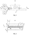
- FIG. 1 shows a schematic representation of an exemplary high-power cladding-pumped fiber laser 20 according to the prior art.
- Laser 20 comprises a segment of an active gain fiber 22, in which a linear resonant cavity 24 formed by a pair of in-fiber gratings that provide a high reflector (HR) 26 and an output coupler (OC) 28.
- a plurality of pump light sources 30 provide a pump light 32 that is fed into the resonant cavity 24 through the high reflector 26.
- Ionic gain within the resonant cavity 24 results in the generation of laser light 34 at a desired signal wavelength along a transmission pathway 36 extending through the device.
- the laser light 34 exits the resonant cavity 24 through output coupler 28, which has relatively low reflectivity.
- the laser light 34 is then provided as the laser output 38.
- Laser 20 further comprises one or more backward ports 40.
- FIG. 2 shows a cross section diagram of an exemplary backward port 40, which comprises a segment of an optical fiber with a core 42 and surrounding cladding 44.
- Backward port 40 is terminated using a cleave 46 having an angle ⁇ of approximately 12 degrees relative to a plane 48 perpendicular to the fiber axis 50.
- Backward-propagating feedback light 52 that enters backward port 40 propagates to cleave 46 and is reflected back into the backward port 40 at an angle ⁇ that causes the feedback light 52 to be reflected into cladding 44 where it is dissipated or absorbed.
- angled cleaves such as cleave 46 illustrated in FIG. 2
- cleave 46 illustrated in FIG. 2 are capable of providing the 62 dB to 72 dB isolation required to prevent enhancement of the Raman-sifted feedback light 52.
- Raman gain can reach power levels at which a significant portion of the Raman-shifted light is reflected back into the laser 20.
- the cleave 46 can itself become a primary source of undesirable feedback.
- Other contributing factors include surface roughness at the cleaved endface and possible degradation due to environmental factors.
- a similar situation presents itself in a counter-pumped architecture.
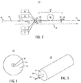
- FIG. 3 shows an exemplary fiber laser 54 according to a practice of the invention.
- Laser 54 comprises a segment of an active gain fiber 56, in which a linear resonant cavity 58 formed by a pair of in-fiber gratings that provide a high reflector (HR) 60 and an output coupler (OC) 62.
- a plurality of pump light sources 64 provide a pump light 66 that is fed into the resonant cavity 58 through the high reflector 60.
- Ionic gain within the resonant cavity 58 results in the generation of laser light 68 at a desired signal wavelength along a transmission pathway 70 extending through the device.
- the laser light 68 exits the resonant cavity 58 through output coupler 62, which has relatively low reflectivity.
- the laser light 68 is then provided as the laser output 72.
- the Raman-shifted light is eliminated from the transmission pathway by providing a backward port 76 at a selected location on the transmission pathway.
- Backward port 76 comprises an optical fiber segment that is terminated with a segment of a filter fiber 78 having a cleaved endface 80 that is suitably angled (e.g., at approximately 12 degrees).
- the filter fiber 78 is configured to have low loss at the signal wavelength and enhanced loss at undesirable wavelengths, i.e., at one or more wavelengths at which Raman feedback occurs.
- a suitable filtering effect for filter fiber 78 can be achieved using techniques known in the art, e.g., through the use of a fiber with a tailored fiber index profile, through the application of photonic bandgap concepts, or the like.
- Backward port 76 and filter fiber 78 comprise respective cores that are spliced to each other.
- the core of filter fiber 78 is fabricated from a material that is chosen to provide good index matching upon splicing with the core material of the backward port 76, thereby eliminating Fresnel reflections.
- the filtering effect provided by the filter fiber 78 then causes at least some of the Raman component to be lost through dissipation or absorption.
- Filter fiber 78 can be tailored to provide a relatively small amount of Raman loss or alternatively can be tailored to provide a larger amount of Raman loss, e.g., in the tens of decibels. With sufficient length, a suitably configured filter fiber can fully eliminate the Raman component in a given fiber laser. According to a further aspect of the invention, a filter fiber is also used to remove any influence of the cleaved endface 80.
- the loss characteristics of filter fiber 78 can be configured according to the needs of a given application. For example, the amount of signal component loss can be modified (i.e., from very low loss to high loss) by modifying the coiling conditions. For applications where the signal component is used to provide a monitoring port output, the signal component can be left largely unaffected. This approach was demonstrated in a forward-pumped oscillator with an 11 ⁇ m core. The oscillator was pumped with 450W, yielding 330 W of signal power.
- Suitable filter fiber designs are described, for example, in U.S. Pat. No. 8,428,409 , which is owned by the assignee of the present invention, and which is incorporated by reference herein in its entirety.
- FIGS. 4 and 5 show, respectively, cross section and isometric views of an exemplary filter fiber 78 according to U.S. Pat. No. 8,428,409 , comprising a raised-index core 82, a depressed-index inner cladding 84, and an undoped outer cladding 86.
- FIGS. 6A-6D show exemplary refractive index profiles 88a-d for the filter fiber illustrated in FIGS. 4 and 5 .
- the central spike 90a-d corresponds to the filter fiber's raised-index core 82
- the trench regions 92a-d correspond to the filter fiber's depressed-index inner cladding 84
- the flat outer regions 94a-d correspond to the filter fiber's undoped outer cladding 86.
- FIG. 7 shows a graph 96 illustrating the relationship between attenuation and wavelength in a prototype filter fiber design according to U.S. Pat. No. 8,428,409 .
- Experimental data was generated for a number of different outer cladding diameters: 122 ⁇ m (curve 98); 123 ⁇ m (curve 100); 124 ⁇ m (curve 102); 125 ⁇ m (curve 104); 132 ⁇ m (curve 106) and 142 ⁇ m (curve 108). Since these fibers were drawn from the same preform, their core diameters are proportional to the cladding diameters, and for example, the core diameter in the 142 ⁇ m clad diameter fiber is about 16.7% larger than that in the 122 ⁇ m clad diameter fiber.
- Curves 98-108 illustrate the described filtering effect: there is a 10 6 order of magnitude difference in attenuation between wavelengths below a specified cutoff wavelength and wavelengths about the cutoff wavelength.
- the fiber laser was configured as shown in FIG. 1 , with an angle-cleave-only termination of the backward port 40.
- the fiber laser was configured as shown in FIG. 3 .
- the backward port 76 was terminated with a 3-meter length of a filter fiber 78 having an angled, cleaved endface 80, as described above.
- the filter fiber 78 had a cutoff wavelength of 1100 nm.
- FIG. 8 shows an optical spectrum 110 of the respective outputs of the first and second configurations.
- Trace 112 shows the output spectrum for the first configuration, which shows a primary peak at the 1070 nm signal component and a secondary peak at 1120 nm, approximately 34 dB below the primary peak.
- Trace 114 shows the output spectrum for the second configuration, which shows the effective suppression of the secondary peak at 1120 nm, compared with an angle-cleave-only termination.
- FIG. 9 shows an exemplary fiber laser 116 according to a further aspect of the invention, in which a filter fiber 118 is used to terminate additional ports in a fiber laser or like device.
- Laser 116 comprises an active fiber 120 having an input end 122 and an output end 124; a high reflector grating (HC) 126 and an output coupler (OC) 128 that, together with the segment of active fiber 120 between them, form a resonant cavity 130; and a plurality of laser diodes 132 that provide a pump light input 134 into the resonant cavity 130, resulting in the generation of a laser light 136 along transmission pathway 138.
- HC high reflector grating
- OC output coupler
- laser 116 further includes a backward port 140, to which filter fiber 118 is connected.
- Filter fiber 118 is terminated at an angled cleave 138 and, as described above, is used to eliminate feedback light 141 at a Raman-shifted wavelength entering the first backward port 140.
- Laser 116 further includes a 2x2 component 140 having first and second backward ports 142, 144 and first and second forward ports 146, 148.
- the lead end of the active fiber 120 is connected to the 2x2 component's first backward port 144.
- the 2x2 component's second backward port 146 and first forward port 148 are each connected to a respective length of filter fiber 152, 154, each of which is terminated at a respective angled cleave 156, 158.
- Filter fibers 152, 154 eliminate light at a Raman-shifted wavelength traveling in both a forward direction 160 and backward direction 162.
- the filtered laser light is provided as an output 164 at the 2x2 component's second forward port 150.
- a filter fiber with low loss at a signal wavelength is used in between a laser cavity and a delivery fiber to prevent destabilization of the cavity from backward Raman light potentially generated in the delivery fiber, which can have a significant length (i.e., in the tens of meters).
- a filter fiber is used in a high-power optical device to provide a termination that strongly suppresses an undesirable Raman wavelength component, as described above, and in addition dissipates signal power, ranging from 10s to 100s of watts, in a safe way.
- a filter-fiber-based termination automatically solves this issue. Beyond a cutoff wavelength, loss in a filter fiber increases with wavelength.
- loss at the signal wavelength can be configured to be moderate (e.g., ⁇ 15 dB/m), allowing for gradual dissipation of backward signal light along the fiber length.
- the loss at the Raman component can be configured to be very high, which provides a high degree of feedback suppression.
- the use of suitably configured filter fibers is generalized to provide all terminations in an optical device.
- a Raman filter fiber is connected into the main optical path, and is further used to isolate the laser cavity from all external sources of light at one or more undesirable Raman wavelengths.
- the output includes light at both infrared and visible wavelengths.
- the visible light component allows the direction of an infrared laser beam to a specific target without the need for special infrared viewers.
- a filter fiber is connected between a low-power visible light source and the laser's resonant cavity in order to protect the visible light source from back-reflected infrared laser light impinging onto its surface.
- a visible light source is connected to a laser cavity by means of a wavelength combiner, such as a wavelength division multiplexer (WDM) or like device.
- a wavelength combiner such as a wavelength division multiplexer (WDM) or like device.
- WDM wavelength division multiplexer
- the extinction ratio of typical wavelength combiners is, in general, insufficient to completely isolate the visible light source. Feedback of high-power infrared laser light through the wavelength combiner may result in damage to the visible light source.
- prior-art systems typically employ additional isolators, cascaded wavelength multiplexers, attenuators, and the like in order to protect and isolate the visible source.
- FIG. 10 shows a schematic of a fiber laser system 166 according to this aspect of the invention.
- Laser system 166 comprises a segment of an active gain fiber 168 having a linear resonant cavity 170 formed by a pair of gratings: a high reflector (HR) grating 172 and an output coupler (OC) grating 174.
- HR high reflector
- OC output coupler
- a plurality of pump sources 176 provides a pump light input 178 that is fed into the resonant cavity 170 through the high reflector grating 172, resulting in the generation of an infrared laser light 180 along transmission pathway 182 that exits the resonant cavity 170 through the output coupler grating 174.
- Laser system 166 further includes a backward port 184, to which is connected a visible light source 186 for launching a visible light 188 into the transmission pathway 182.
- the output 190 of laser system 166 includes both the infrared laser light 180 and the visible light 188.
- Visible light source 186 is connected to the backward port 184 by means of a filter fiber 192.
- the filter fiber 192 transmits visible light 188 from the visible light source 186 into the transmission pathway 182, while suppressing undesired infrared light 194 reflected from the resonant cavity 170 back towards the visible light source 186.
- Laser system 166 is suitable for use, for example, in an application in which signal monitoring capabilities are not required in the backward port 184 of the laser's resonant cavity 170.
- ASE amplified spontaneous emission noise
Landscapes
- Physics & Mathematics (AREA)
- Electromagnetism (AREA)
- Engineering & Computer Science (AREA)
- Plasma & Fusion (AREA)
- Optics & Photonics (AREA)
- Optical Modulation, Optical Deflection, Nonlinear Optics, Optical Demodulation, Optical Logic Elements (AREA)
- Semiconductor Lasers (AREA)
- Light Guides In General And Applications Therefor (AREA)
- Optical Fibers, Optical Fiber Cores, And Optical Fiber Bundles (AREA)
- Lasers (AREA)
- Optical Communication System (AREA)
- Automation & Control Theory (AREA)
Applications Claiming Priority (1)
| Application Number | Priority Date | Filing Date | Title |
|---|---|---|---|
| US14/669,760 US20160285230A1 (en) | 2015-03-26 | 2015-03-26 | Systems and techniques for termination of ports in fiber lasers |
Publications (2)
| Publication Number | Publication Date |
|---|---|
| EP3086420A2 true EP3086420A2 (de) | 2016-10-26 |
| EP3086420A3 EP3086420A3 (de) | 2017-01-04 |
Family
ID=55628875
Family Applications (1)
| Application Number | Title | Priority Date | Filing Date |
|---|---|---|---|
| EP16162159.4A Withdrawn EP3086420A3 (de) | 2015-03-26 | 2016-03-24 | Systeme und techniken zur beendigung der zugänge in faserlasern |
Country Status (3)
| Country | Link |
|---|---|
| US (1) | US20160285230A1 (de) |
| EP (1) | EP3086420A3 (de) |
| JP (1) | JP2016184730A (de) |
Families Citing this family (3)
| Publication number | Priority date | Publication date | Assignee | Title |
|---|---|---|---|---|
| JP2019079849A (ja) * | 2017-10-20 | 2019-05-23 | 株式会社フジクラ | ファイバレーザシステム、方法及び製造方法 |
| US12176673B2 (en) | 2018-12-28 | 2024-12-24 | Nlight, Inc. | Optical fiber devices and methods for reducing stimulated Raman scattering (SRS) light emissions from a resonant cavity |
| US11489311B2 (en) * | 2019-10-22 | 2022-11-01 | Lumentum Operations Llc | Optical amplifier |
Citations (1)
| Publication number | Priority date | Publication date | Assignee | Title |
|---|---|---|---|---|
| US8428409B2 (en) | 2009-05-11 | 2013-04-23 | Ofs Fitel, Llc | Filter fiber for use in Raman lasing applications and techniques for manufacturing same |
Family Cites Families (9)
| Publication number | Priority date | Publication date | Assignee | Title |
|---|---|---|---|---|
| US5812712A (en) * | 1997-02-26 | 1998-09-22 | E-Tek Dynamics, Inc. | Fiber bragg grating-circulator systems having reduced ASE |
| JP3264246B2 (ja) * | 1998-03-31 | 2002-03-11 | 日本電気株式会社 | 光増幅器 |
| US6731423B1 (en) * | 2001-08-15 | 2004-05-04 | Neumann Information Systems Inc | Optical amplifier and method |
| JP2006064852A (ja) * | 2004-08-25 | 2006-03-09 | Kansai Electric Power Co Inc:The | 分散補償器 |
| US7876803B1 (en) * | 2007-03-21 | 2011-01-25 | Lockheed Martin Corporation | High-power, pulsed ring fiber oscillator and method |
| KR100864837B1 (ko) * | 2007-06-15 | 2008-10-23 | 한국전자통신연구원 | 라만 공동을 갖는 라만 광증폭기를 이용한 이득고정형광증폭 장치 |
| JP5677467B2 (ja) * | 2011-01-18 | 2015-02-25 | 古河電気工業株式会社 | ファイバレーザ装置およびレーザ光照射位置の位置決め方法 |
| JP6140072B2 (ja) * | 2011-05-31 | 2017-05-31 | 古河電気工業株式会社 | レーザ装置および加工装置 |
| EP2769444A4 (de) * | 2011-10-19 | 2015-08-05 | Ofs Fitel Llc | Kaskadiertes raman-lasersystem |
-
2015
- 2015-03-26 US US14/669,760 patent/US20160285230A1/en not_active Abandoned
-
2016
- 2016-03-24 EP EP16162159.4A patent/EP3086420A3/de not_active Withdrawn
- 2016-03-25 JP JP2016061001A patent/JP2016184730A/ja active Pending
Patent Citations (1)
| Publication number | Priority date | Publication date | Assignee | Title |
|---|---|---|---|---|
| US8428409B2 (en) | 2009-05-11 | 2013-04-23 | Ofs Fitel, Llc | Filter fiber for use in Raman lasing applications and techniques for manufacturing same |
Also Published As
| Publication number | Publication date |
|---|---|
| JP2016184730A (ja) | 2016-10-20 |
| EP3086420A3 (de) | 2017-01-04 |
| US20160285230A1 (en) | 2016-09-29 |
Similar Documents
| Publication | Publication Date | Title |
|---|---|---|
| US8351111B2 (en) | Cascaded raman fiber laser system based on filter fiber | |
| US7417791B2 (en) | Optical amplifier for amplifying multi-wavelength light | |
| US8885993B2 (en) | Dual-index optical pump stripper assembly | |
| CN109599740A (zh) | 具有抑制sbs作用的双向泵浦双包层光纤激光放大器 | |
| US8982452B2 (en) | All-in-one raman fiber laser | |
| US9360625B2 (en) | Pump absorption and efficiency for fiber lasers/amplifiers | |
| KR102350424B1 (ko) | 기생 광 손실을 유도하기 위한 기구를 갖는 섬유 레이저 시스템 | |
| Lin et al. | Simple design of Yb-doped fiber laser with an output power of 2 kW | |
| US7864410B2 (en) | Optical active device having optical amplifying sections cascaded on a path for propagating input light with a predetermined wavelength | |
| EP3086420A2 (de) | Systeme und techniken zur beendigung der zugänge in faserlasern | |
| WO2019146627A1 (ja) | フィルタ素子、レーザ装置、ファイバレーザ装置、フィルタ方法、及びレーザ装置の製造方法 | |
| JP5984813B2 (ja) | 低雑音を示すレーザ・キャビティ | |
| US12142889B2 (en) | Methods for SRS protection of laser components and apparatus providing SRS protection | |
| JP2013537002A5 (de) | ||
| KR20010041602A (ko) | 초광대역의 저-노이즈 게인-플랫된 희토류 도프처리된섬유 증폭기 | |
| Arbore et al. | 30-dB gain at 1500 nm in S-band erbium-doped silica fiber with distributed ASE suppression | |
| Morasse et al. | Chirped tilted fiber bragg gratings used as intracavity ase band-stop filters in a high power 1018 nm fiber laser | |
| Yucel et al. | The comparison of the gain flattening techniques EDFA configurations in the C/L band | |
| US7495825B2 (en) | Integration of a gain equalization filter in a gain medium | |
| CN115428277A (zh) | 通过抑制受激拉曼散射提高激光效率的具有腔内光纤布拉格光栅的光纤激光谐振器 | |
| US20250372935A1 (en) | Distributed filters for suppression of parasitic processes in fiber laser systems | |
| Wetter et al. | High core and cladding isolation termination for high-power lasers and amplifiers | |
| WO2019172398A1 (ja) | 余剰光除去装置及びファイバレーザ | |
| US20250015551A1 (en) | Hybrid-pumped fiber amplifier |
Legal Events
| Date | Code | Title | Description |
|---|---|---|---|
| PUAI | Public reference made under article 153(3) epc to a published international application that has entered the european phase |
Free format text: ORIGINAL CODE: 0009012 |
|
| AK | Designated contracting states |
Kind code of ref document: A2 Designated state(s): AL AT BE BG CH CY CZ DE DK EE ES FI FR GB GR HR HU IE IS IT LI LT LU LV MC MK MT NL NO PL PT RO RS SE SI SK SM TR |
|
| AX | Request for extension of the european patent |
Extension state: BA ME |
|
| PUAL | Search report despatched |
Free format text: ORIGINAL CODE: 0009013 |
|
| RIC1 | Information provided on ipc code assigned before grant |
Ipc: H01S 3/067 20060101AFI20161124BHEP |
|
| AK | Designated contracting states |
Kind code of ref document: A3 Designated state(s): AL AT BE BG CH CY CZ DE DK EE ES FI FR GB GR HR HU IE IS IT LI LT LU LV MC MK MT NL NO PL PT RO RS SE SI SK SM TR |
|
| AX | Request for extension of the european patent |
Extension state: BA ME |
|
| 17P | Request for examination filed |
Effective date: 20170630 |
|
| RBV | Designated contracting states (corrected) |
Designated state(s): AL AT BE BG CH CY CZ DE DK EE ES FI FR GB GR HR HU IE IS IT LI LT LU LV MC MK MT NL NO PL PT RO RS SE SI SK SM TR |
|
| STAA | Information on the status of an ep patent application or granted ep patent |
Free format text: STATUS: THE APPLICATION IS DEEMED TO BE WITHDRAWN |
|
| 18D | Application deemed to be withdrawn |
Effective date: 20181002 |