EP3085943A1 - Abgasrückführungsbaugruppe mit abgaskrümmer - Google Patents
Abgasrückführungsbaugruppe mit abgaskrümmer Download PDFInfo
- Publication number
- EP3085943A1 EP3085943A1 EP16159192.0A EP16159192A EP3085943A1 EP 3085943 A1 EP3085943 A1 EP 3085943A1 EP 16159192 A EP16159192 A EP 16159192A EP 3085943 A1 EP3085943 A1 EP 3085943A1
- Authority
- EP
- European Patent Office
- Prior art keywords
- exhaust gas
- gas recirculation
- cylinder head
- exhaust
- recirculation assembly
- Prior art date
- Legal status (The legal status is an assumption and is not a legal conclusion. Google has not performed a legal analysis and makes no representation as to the accuracy of the status listed.)
- Granted
Links
Images

Classifications
-
- F—MECHANICAL ENGINEERING; LIGHTING; HEATING; WEAPONS; BLASTING
- F02—COMBUSTION ENGINES; HOT-GAS OR COMBUSTION-PRODUCT ENGINE PLANTS
- F02M—SUPPLYING COMBUSTION ENGINES IN GENERAL WITH COMBUSTIBLE MIXTURES OR CONSTITUENTS THEREOF
- F02M26/00—Engine-pertinent apparatus for adding exhaust gases to combustion-air, main fuel or fuel-air mixture, e.g. by exhaust gas recirculation [EGR] systems
- F02M26/13—Arrangement or layout of EGR passages, e.g. in relation to specific engine parts or for incorporation of accessories
- F02M26/41—Arrangement or layout of EGR passages, e.g. in relation to specific engine parts or for incorporation of accessories characterised by the arrangement of the recirculation passage in relation to the engine, e.g. to cylinder heads, liners, spark plugs or manifolds; characterised by the arrangement of the recirculation passage in relation to specially adapted combustion chambers
-
- F—MECHANICAL ENGINEERING; LIGHTING; HEATING; WEAPONS; BLASTING
- F02—COMBUSTION ENGINES; HOT-GAS OR COMBUSTION-PRODUCT ENGINE PLANTS
- F02F—CYLINDERS, PISTONS OR CASINGS, FOR COMBUSTION ENGINES; ARRANGEMENTS OF SEALINGS IN COMBUSTION ENGINES
- F02F1/00—Cylinders; Cylinder heads
- F02F1/24—Cylinder heads
- F02F1/42—Shape or arrangement of intake or exhaust channels in cylinder heads
-
- F—MECHANICAL ENGINEERING; LIGHTING; HEATING; WEAPONS; BLASTING
- F02—COMBUSTION ENGINES; HOT-GAS OR COMBUSTION-PRODUCT ENGINE PLANTS
- F02M—SUPPLYING COMBUSTION ENGINES IN GENERAL WITH COMBUSTIBLE MIXTURES OR CONSTITUENTS THEREOF
- F02M26/00—Engine-pertinent apparatus for adding exhaust gases to combustion-air, main fuel or fuel-air mixture, e.g. by exhaust gas recirculation [EGR] systems
- F02M26/12—Engine-pertinent apparatus for adding exhaust gases to combustion-air, main fuel or fuel-air mixture, e.g. by exhaust gas recirculation [EGR] systems characterised by means for attaching parts of an EGR system to each other or to engine parts
-
- F—MECHANICAL ENGINEERING; LIGHTING; HEATING; WEAPONS; BLASTING
- F02—COMBUSTION ENGINES; HOT-GAS OR COMBUSTION-PRODUCT ENGINE PLANTS
- F02M—SUPPLYING COMBUSTION ENGINES IN GENERAL WITH COMBUSTIBLE MIXTURES OR CONSTITUENTS THEREOF
- F02M26/00—Engine-pertinent apparatus for adding exhaust gases to combustion-air, main fuel or fuel-air mixture, e.g. by exhaust gas recirculation [EGR] systems
- F02M26/13—Arrangement or layout of EGR passages, e.g. in relation to specific engine parts or for incorporation of accessories
- F02M26/22—Arrangement or layout of EGR passages, e.g. in relation to specific engine parts or for incorporation of accessories with coolers in the recirculation passage
- F02M26/23—Layout, e.g. schematics
- F02M26/25—Layout, e.g. schematics with coolers having bypasses
-
- F—MECHANICAL ENGINEERING; LIGHTING; HEATING; WEAPONS; BLASTING
- F02—COMBUSTION ENGINES; HOT-GAS OR COMBUSTION-PRODUCT ENGINE PLANTS
- F02M—SUPPLYING COMBUSTION ENGINES IN GENERAL WITH COMBUSTIBLE MIXTURES OR CONSTITUENTS THEREOF
- F02M26/00—Engine-pertinent apparatus for adding exhaust gases to combustion-air, main fuel or fuel-air mixture, e.g. by exhaust gas recirculation [EGR] systems
- F02M26/13—Arrangement or layout of EGR passages, e.g. in relation to specific engine parts or for incorporation of accessories
- F02M26/22—Arrangement or layout of EGR passages, e.g. in relation to specific engine parts or for incorporation of accessories with coolers in the recirculation passage
- F02M26/29—Constructional details of the coolers, e.g. pipes, plates, ribs, insulation or materials
- F02M26/30—Connections of coolers to other devices, e.g. to valves, heaters, compressors or filters; Coolers characterised by their location on the engine
-
- F—MECHANICAL ENGINEERING; LIGHTING; HEATING; WEAPONS; BLASTING
- F02—COMBUSTION ENGINES; HOT-GAS OR COMBUSTION-PRODUCT ENGINE PLANTS
- F02M—SUPPLYING COMBUSTION ENGINES IN GENERAL WITH COMBUSTIBLE MIXTURES OR CONSTITUENTS THEREOF
- F02M26/00—Engine-pertinent apparatus for adding exhaust gases to combustion-air, main fuel or fuel-air mixture, e.g. by exhaust gas recirculation [EGR] systems
- F02M26/13—Arrangement or layout of EGR passages, e.g. in relation to specific engine parts or for incorporation of accessories
- F02M26/22—Arrangement or layout of EGR passages, e.g. in relation to specific engine parts or for incorporation of accessories with coolers in the recirculation passage
- F02M26/29—Constructional details of the coolers, e.g. pipes, plates, ribs, insulation or materials
- F02M26/32—Liquid-cooled heat exchangers
-
- F—MECHANICAL ENGINEERING; LIGHTING; HEATING; WEAPONS; BLASTING
- F28—HEAT EXCHANGE IN GENERAL
- F28D—HEAT-EXCHANGE APPARATUS, NOT PROVIDED FOR IN ANOTHER SUBCLASS, IN WHICH THE HEAT-EXCHANGE MEDIA DO NOT COME INTO DIRECT CONTACT
- F28D21/00—Heat-exchange apparatus not covered by any of the groups F28D1/00 - F28D20/00
- F28D21/0001—Recuperative heat exchangers
- F28D21/0003—Recuperative heat exchangers the heat being recuperated from exhaust gases
Definitions
- the invention relates to an exhaust gas recirculation assembly with a cylinder head and an exhaust manifold.
- exhaust gas is usually taken from the exhaust pipe and admixed with the combustion air. This is for the reduction of nitrogen oxides (NOx) and compliance with emission limits in accordance with applicable regulations.
- NOx nitrogen oxides
- the exhaust gas can for example be taken directly from the exhaust manifold and be reintroduced on the intake side of the internal combustion engine. Depending on the conditions, the exhaust gas is either cooled before it is supplied to the combustion air, or it is supplied uncooled.
- the exhaust gas recirculation assembly In order to cool the exhaust gas, the exhaust gas recirculation assembly to an exhaust gas cooler, through which the exhaust gas can be performed. If the exhaust gas is to be supplied uncooled, a bypass is opened (for example, by a vacuum box that opens or closes a bypass flap valve), so that the exhaust gas flows through a bypass channel and bypasses the heat exchanger.
- the amount of exhaust gas that is recycled as a whole, is controlled by a control valve that allows, for example, map-controlled the desired volume flow rate.
- the object of the invention is to provide an exhaust gas recirculation assembly, which is characterized by a small space required.
- the invention provides in an exhaust gas recirculation assembly of the type mentioned above, that the exhaust manifold is provided with an exhaust gas recirculation branch, which is directly connected to an exhaust gas recirculation inlet in the cylinder head.
- the invention is based on the basic concept of not leading the exhaust branched off at the exhaust manifold by hoses to be mounted separately on the exhaust manifold, but instead introducing it directly from the exhaust manifold into the cylinder head. As a result, a highly integrated solution is created, which is characterized by small space.
- an exhaust manifold gasket is provided, through which passes the connection between the exhaust gas recirculation branch and the exhaust gas recirculation inlet.
- the sealing of the exhaust gas recirculation channel thus takes place through a modified exhaust manifold gasket, so that no additional installation effort arises.
- a heat exchanger branch branches off from the cylinder head, through which exhaust gas can be conducted to a heat exchanger. This makes it possible to supply the recirculated exhaust gas to a heat exchanger so that it can be cooled in the desired manner.
- a heat exchanger is attached to the cylinder head, which is connected to the heat exchanger branch. This results in a compact design that requires no external pipes or hoses.
- the heat exchanger is preferably provided with an exhaust gas recirculation valve, so that the amount of exhaust gas to be recirculated and flowing through the heat exchanger can be controlled.
- bypass is preferably integrated.
- the bypass makes it possible to recirculate exhaust gas without cooling.
- the integration into the cylinder head in turn results in a very compact design, which requires no external hoses or pipes.
- the bypass channel is preferably associated with a bypass valve which is mounted on the cylinder head.
- the bypass valve makes it possible to control the volume flow of the exhaust gas flowing through the bypass passage.
- bypass channel is air-gap-insulated. As a result, the thermal loads of the cylinder head can be reduced.
- the exhaust gas recirculation valve and / or the bypass valve is a control valve.
- a bypass flap which can be switched only between an open and a closed state in the prior art, provides an adjustable bypass valve great advantages.
- flow losses are reduced by a volume flow through the exhaust gas recirculation system is (at least almost) completely avoided when both valves are closed.
- a cylinder head 10 which serves in a conventional manner to supply intake air to a plurality of cylinders of an internal combustion engine and to remove combustion gases from the cylinders.
- the intake air is provided via an intake system 12, and the combustion gases are exhausted via an exhaust manifold 14.
- a part of the exhaust gas can be taken from the exhaust line of the internal combustion engine and returned to the intake side.
- two different flow paths are possible.
- a first flow path passes through a heat exchanger 16, in which heat can be withdrawn from the exhaust gas.
- a coolant inlet 18 and a coolant outlet 20 are provided.
- an exhaust gas recirculation valve 22 is provided in order to control or regulate the volume flow through the heat exchanger 16.
- a second flow path extends through a bypass channel 24, through which exhaust gas can be passed directly from the exhaust gas to the suction side, bypassing the heat exchanger 16.
- the bypass channel 24 is associated with a bypass valve 26, with which the volume flow through the bypass channel can be controlled or regulated.
- the exhaust gas is here removed from the exhaust system by means of an exhaust gas recirculation branch 30, which is provided on the exhaust manifold 14 and is directly connected to an exhaust gas recirculation inlet 32.
- the exhaust gas recirculation inlet 32 is provided in the cylinder head 10.
- the exhaust gas recirculation inlet 32 branches then in the cylinder head in a heat exchanger branch 34 and a bypass branch 36th
- the heat exchanger branch 34 opens on a side surface of the cylinder head 10 and leads directly to the heat exchanger 16, which is attached to the cylinder head 10.
- the bypass branch 36 leads to the bypass channel 24, which is integrated here into the cylinder head 10.
- the bypass channel 24 is designed here with air gap insulation with an inner sleeve 38, so that the thermal loads of the cylinder head are reduced and a higher exhaust gas recirculation gas temperature can be achieved.
- the inner sleeve 38 can be inserted into a hole open towards the outside of the cylinder head, which is then closed with a locking screw 40.
- the exhaust-gas recirculation branch 30 opens directly into the bypass branch 36, namely into the opening which, at the in FIG. 3 shown embodiment of the screw plug 40 is closed.
- the exhaust gas recirculation branch 30 extends in the embodiment of the FIG. 3a further to the side than in the embodiment of the FIG. 3 the case is.
- the advantage of direct recirculation of the exhaust gas into the cylinder head is that no external pipes or hoses are needed to carry the exhaust gas.
- the expense of mounting such pipes or hoses is avoided because the exhaust gas recirculation branch is directly connected to the exhaust gas recirculation inlet when the exhaust manifold 14 is attached to the cylinder head 10.
- a slightly modified exhaust manifold gasket can be used, which seals in the region of the interface between the exhaust gas recirculation branch 30 and the exhaust gas recirculation inlet 32.
Landscapes
- Engineering & Computer Science (AREA)
- Mechanical Engineering (AREA)
- General Engineering & Computer Science (AREA)
- Chemical & Material Sciences (AREA)
- Combustion & Propulsion (AREA)
- Physics & Mathematics (AREA)
- Thermal Sciences (AREA)
- Exhaust-Gas Circulating Devices (AREA)
- Cylinder Crankcases Of Internal Combustion Engines (AREA)
Abstract
Description
- Die Erfindung betrifft eine Abgasrückführungsbaugruppe mit einem Zylinderkopf und einem Abgaskrümmer.
- Bei Verbrennungskraftmaschinen wird üblicherweise Abgas aus der Abgasleitung entnommen und der Verbrennungsluft beigemischt. Dies dient der Reduktion von Stickoxiden (NOx) und der Einhaltung von Emissionsgrenzen gemäß den geltenden Vorschriften.
- Das Abgas kann beispielsweise unmittelbar am Abgaskrümmer entnommen werden und auf der Ansaugseite der Verbrennungskraftmaschine wieder eingeleitet werden. In Abhängigkeit von den Rahmenbedingungen wird das Abgas entweder gekühlt, bevor es der Verbrennungsluft zugeführt wird, oder es wird ungekühlt zugeführt.
- Um das Abgas kühlen zu können, weist die Abgasrückführungsbaugruppe einen Abgaskühler auf, durch den das Abgas geführt werden kann. Wenn das Abgas ungekühlt zugeführt werden soll, wird ein Bypass geöffnet (beispielsweise durch eine Unterdruckdose, die ein Bypass-Klappenventil öffnet oder schließt), sodass das Abgas durch einen Bypasskanal strömt und den Wärmetauscher umgeht. Die Menge des Abgases, das insgesamt rückgeführt wird, wird dabei gesteuert durch ein Regelventil, das beispielsweise kennfeldgesteuert den gewünschten Volumendurchsatz ermöglicht.
- Im Hinblick auf die zunehmende Komplexität der Verbrennungskraftmaschinen und die verschiedenen Systeme, die zum Erzielen eines niedrigen Kraftstoffverbrauchs und geringer Abgasemissionen eingesetzt werden, ist der Bauraum, der für eine Abgasrückführungsbaugruppe notwendig ist, immer ein wichtiges Thema.
- Die Aufgabe der Erfindung besteht daher darin, eine Abgasrückführungsbaugruppe zu schaffen, die sich durch einen geringen notwendigen Bauraum auszeichnet.
- Zur Lösung dieser Aufgabe ist erfindungsgemäß bei einer Abgasrückführungsbaugruppe der eingangs genannten Art vorgesehen, dass der Abgaskrümmer mit einem Abgasrückführabzweig versehen ist, der unmittelbar mit einem Abgasrückführeinlass im Zylinderkopf verbunden ist. Die Erfindung beruht auf dem Grundkonzept, das am Abgaskrümmer abgezweigte Abgas nicht durch separat am Abgaskrümmer zu montierende Schläuche zu führen, sondern vom Abgaskrümmer direkt in den Zylinderkopf einzuleiten. Hierdurch ist eine hochintegrierte Lösung geschaffen, die sich durch geringen Bauraum auszeichnet. Weiterhin ergibt sich ein geringerer Montageaufwand, da der Abgasrückführabzweig des Abgaskrümmers automatisch mit dem Abgasrückführeinlass im Zylinderkopf verbunden wird, wenn der Abgaskrümmer am Zylinderkopf montiert wird. Weiterhin müssen keine thermischen Entkopplungsmaßnahmen getroffen werden, wie dies im Stand der Technik zum thermischen Längenausgleich notwendig ist; dort ist beispielsweise ein Wellbalg notwendig, der zu zusätzlichen Kosten führt.
- Gemäß einer bevorzugten Ausführungsform ist eine Abgaskrümmerdichtung vorgesehen, durch die hindurch die Verbindung zwischen Abgasrückführabzweig und Abgasrückführeinlass verläuft. Die Abdichtung des Abgasrückführkanals erfolgt also durch eine modifizierte Abgaskrümmerdichtung, sodass kein zusätzlicher Montageaufwand entsteht.
- Vorzugsweise ist vorgesehen, dass vom Zylinderkopf ein Wärmetauscherabzweig abgeht, durch den Abgas zu einem Wärmetauscher geleitet werden kann. Dies ermöglicht es, das rückzuführende Abgas einem Wärmetauscher zuzuführen, sodass es in der gewünschten Weise gekühlt werden kann.
- Vorzugsweise ist vorgesehen, dass am Zylinderkopf ein Wärmetauscher angebracht ist, der an den Wärmetauscherabzweig angeschlossen ist. Hierdurch ergibt sich eine kompakte Konstruktion, die keine externen Rohre oder Schläuche erfordert.
- Der Wärmetauscher ist vorzugsweise mit einem Abgasrückführungsventil versehen, sodass die Menge des rückzuführenden und über den Wärmetauscher strömenden Abgases gesteuert werden kann.
- In den Zylinderkopf ist vorzugsweise ein Bypass integriert. Der Bypass ermöglicht es, Abgas ungekühlt zurückzuführen. Durch die Integration in den Zylinderkopf ergibt sich wiederum ein sehr kompakter Aufbau, der keine externen Schläuche oder Rohre erfordert.
- Dem Bypasskanal ist vorzugsweise ein Bypassventil zugeordnet, das am Zylinderkopf angebracht ist. Das Bypassventil ermöglicht es, den Volumenstrom des Abgases zu steuern, das durch den Bypasskanal strömt.
- Vorzugsweise ist vorgesehen, dass der Bypasskanal luftspaltisoliert ist. Hierdurch lassen sich die thermischen Belastungen des Zylinderkopfes reduzieren.
- Vorzugsweise ist vorgesehen, dass das Abgasrückführungsventil und/oder das Bypassventil ein Regelventil ist. Dies ermöglicht es, den Volumenstrom an rückgeführtem Abgas präzise auf jeweils optimale Werte einzustellen. Insbesondere im Vergleich mit einer Bypassklappe, die im Stand der Technik lediglich zwischen einem geöffnetem und einem geschlossenen Zustand geschaltet werden kann, bietet ein regelbares Bypassventil große Vorteile. Weiterhin werden Strömungsverluste verringert, indem ein Volumenstrom durch das Abgasrückführungssystem (zumindest nahezu) vollständig vermieden ist, wenn beide Ventile geschlossen sind.
- Die Erfindung wird nachfolgend anhand einer Ausführungsform beschrieben, die in den beigefügten Zeichnungen dargestellt ist. In diesen zeigen:
-
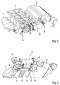
Figur 1 in einer perspektivischen Explosionsansicht einen Zylinderkopf mit Abgasrückführungsbaugruppe; -
Figur 2 den Zylinderkopf vonFigur 1 mit Abgasrückführungsbaugruppe in einer ersten perspektivischen Ansicht; -
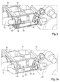
Figur 3 den Zylinderkopf mit Abgasrückführungsbaugruppe in einer zweiten perspektivischen Ansicht; -
Figur 3a den Zylinderkopf vonFigur 3 in einer Ausführungsvariante; und -
Figur 4 in einer schematischen, perspektivischen Ansicht die Bauteile der Abgasrückführungsbaugruppe. - Anhand der
Figuren 1 und 2 wird nachfolgend der grundlegende Aufbau einer Abgasrückführungsbaugruppe erläutert, wie sie im Rahmen der vorliegenden Erfindung ausgeführt ist. - Es ist ein Zylinderkopf 10 zu sehen, der in an sich bekannter Weise dazu dient, mehreren Zylindern einer Verbrennungskraftmaschine Ansaugluft zuzuführen und Verbrennungsgase von den Zylindern abzuführen. Die Ansaugluft wird über ein Ansaugsystem 12 bereitgestellt, und die Verbrennungsgase werden über einen Abgaskrümmer 14 abgeführt.
- Bei bestimmten Betriebszuständen kann ein Teil des Abgases aus dem Abgasstrang der Verbrennungskraftmaschine entnommen und zur Ansaugseite zurückgeführt werden. Hierfür sind zwei unterschiedliche Strömungswege möglich.
- Ein erster Strömungsweg verläuft durch einen Wärmetauscher 16, in welchem dem Abgas Wärme entzogen werden kann. Zu diesem Zweck sind ein Kühlmitteleinlass 18 und ein Kühlmittelauslass 20 vorgesehen. Um den Volumenstrom durch den Wärmetauscher 16 zu steuern oder zu regeln, ist ein Abgasrückführungsventil 22 vorgesehen.
- Ein zweiter Strömungsweg verläuft durch einen Bypasskanal 24, durch den Abgas unter Umgehung des Wärmetauschers 16 direkt von der Abgas- zur Ansaugseite geleitet werden kann. Dem Bypasskanal 24 ist ein Bypassventil 26 zugeordnet, mit dem der Volumenstrom durch den Bypasskanal gesteuert oder geregelt werden kann.
- Das Abgas wird hier aus dem Abgasstrang mittels eines Abgasrückführabzweigs 30 entnommen, der am Abgaskrümmer 14 vorgesehen ist und unmittelbar mit einem Abgasrückführeinlass 32 verbunden ist.
- Bei der in
Figur 3 gezeigten Ausführungsform ist der Abgasrückführeinlass 32 im Zylinderkopf 10 vorgesehen. Der Abgasrückführeinlass 32 verzweigt sich dann im Zylinderkopf in einen Wärmetauscherabzweig 34 und einen Bypassabzweig 36. - Der Wärmetauscherabzweig 34 mündet an einer Seitenfläche des Zylinderkopfes 10 und führt unmittelbar zum Wärmetauscher 16, der am Zylinderkopf 10 angebracht ist. Der Bypassabzweig 36 führt zum Bypasskanal 24, der hier in den Zylinderkopf 10 integriert ist. Der Bypasskanal 24 ist hier luftspaltisoliert mit einer Innenhülse 38 ausgeführt, sodass die thermischen Belastungen des Zylinderkopfes reduziert sind und eine höhere Abgasrückführ-Gastemperatur erreicht werden kann.
- Die Innenhülse 38 kann in eine zur Außenseite des Zylinderkopfes hin geöffnete Bohrung eingesetzt werden, die dann mit einer Verschlussschraube 40 verschlossen wird.
- Bei der in
Figur 3a gezeigten Ausführungsvariante mündet der Abgasrückführabzweig 30 unmittelbar in den Bypassabzweig 36, nämlich in die Öffnung, die bei der inFigur 3 gezeigten Ausführungsform von der Verschlussschraube 40 verschlossen ist. Zu diesem Zweck erstreckt sich der Abgasrückführabzweig 30 bei der Ausführungsvariante derFigur 3a weiter zur Seite, als dies bei der Ausführungsform derFigur 3 der Fall ist. - Der Vorteil der unmittelbaren Rückführung des Abgases in den Zylinderkopf besteht darin, dass keine externen Rohre oder Schläuche notwendig sind, um das Abgas zu führen. Außerdem wird der Aufwand des Montierens solcher Rohre oder Schläuche vermieden, da der Abgasrückführabzweig unmittelbar mit dem Abgasrückführeinlass dann verbunden wird, wenn der Abgaskrümmer 14 am Zylinderkopf 10 angebracht wird. Zur Abdichtung kann eine geringfügig modifizierte Abgaskrümmerdichtung verwendet werden, die im Bereich der Schnittstelle zwischen dem Abgasrückführabzweig 30 und dem Abgasrückführeinlass 32 abdichtet.
- Zusätzlich zum erheblichen Bauraumgewinn wird die Robustheit der Abgasrückführungsbaugruppe erhöht, da keinerlei Maßnahmen für einen thermischen Längenausgleich im Bereich des Abgasrückführabzweigs getroffen werden müssen.
Claims (10)
- Abgasrückführungsbaugruppe mit einem Zylinderkopf (10) und einem Abgaskrümmer (14), dadurch gekennzeichnet, dass der Abgaskrümmer (14) mit einem Abgasrückführabzweig (30) versehen ist, der unmittelbar mit einem Abgasrückführeinlass (32) im Zylinderkopf (10) verbunden ist.
- Abgasrückführungsbaugruppe nach Anspruch 1, dadurch gekennzeichnet, dass eine Abgaskrümmerdichtung vorgesehen ist, durch die hindurch die Verbindung zwischen Abgasrückführabzweig (30) und Abgasrückführeinlass (32) verläuft.
- Abgasrückführungsbaugruppe nach Anspruch 1 oder Anspruch 2, dadurch gekennzeichnet, dass vom Zylinderkopf (10) ein Wärmetauscherabzweig (34) abgeht, durch den Abgas zu einem Wärmetauscher (16) geleitet werden kann.
- Abgasrückführungsbaugruppe nach Anspruch 1 oder Anspruch 2, dadurch gekennzeichnet, dass der Abgasrückführabzweig (30) unmittelbar in einen Bypasskanal (36) mündet.
- Abgasrückführungsbaugruppe nach einem der vorhergehenden Ansprüche, dadurch gekennzeichnet, dass am Zylinderkopf (10) ein Wärmetauscher (16) angebracht ist, der an den Wärmetauscherabzweig (34) angeschlossen ist.
- Abgasrückführungsbaugruppe nach Anspruch 5, dadurch gekennzeichnet, dass der Wärmetauscher (16) mit einem Abgasrückführungsventil (22) versehen ist.
- Abgasrückführungsbaugruppe nach einem der vorhergehenden Ansprüche, dadurch gekennzeichnet, dass in den Zylinderkopf (10) ein Bypasskanal (24) integriert ist.
- Abgasrückführungsbaugruppe nach Anspruch 7, dadurch gekennzeichnet, dass dem Bypasskanal (24) ein Bypassventil (26) zugeordnet ist, das am Zylinderkopf (10) angebracht ist.
- Abgasrückführungsbaugruppe nach Anspruch 7 oder Anspruch 8, dadurch gekennzeichnet, dass der Bypasskanal (24) luftspaltisoliert ist.
- Abgasrückführungsbaugruppe nach Anspruch 8 oder Anspruch 9, dadurch gekennzeichnet, dass das Ventil (22, 26) ein Regelventil ist.
Applications Claiming Priority (1)
| Application Number | Priority Date | Filing Date | Title |
|---|---|---|---|
| DE102015206891.9A DE102015206891A1 (de) | 2015-04-16 | 2015-04-16 | Abgasrückführungsbaugruppe mit Abgaskrümmer |
Publications (2)
| Publication Number | Publication Date |
|---|---|
| EP3085943A1 true EP3085943A1 (de) | 2016-10-26 |
| EP3085943B1 EP3085943B1 (de) | 2020-04-29 |
Family
ID=55532151
Family Applications (1)
| Application Number | Title | Priority Date | Filing Date |
|---|---|---|---|
| EP16159192.0A Active EP3085943B1 (de) | 2015-04-16 | 2016-03-08 | Abgasrückführungsbaugruppe mit abgaskrümmer |
Country Status (2)
| Country | Link |
|---|---|
| EP (1) | EP3085943B1 (de) |
| DE (1) | DE102015206891A1 (de) |
Cited By (4)
| Publication number | Priority date | Publication date | Assignee | Title |
|---|---|---|---|---|
| EP3722587A1 (de) * | 2019-04-12 | 2020-10-14 | Borgwarner Emissions Systems Spain, S.L.U. | Abgasmanagementsystem |
| EP4253749A1 (de) * | 2022-03-31 | 2023-10-04 | Suzuki Motor Corporation | Agr-vorrichtung für einen verbrennungsmotor |
| EP4119786A4 (de) * | 2020-03-13 | 2024-04-17 | Yanmar Power Technology Co., Ltd. | Brennkraftmaschine |
| EP4253752B1 (de) * | 2022-03-31 | 2026-01-14 | Suzuki Motor Corporation | Brennkraftmaschine |
Families Citing this family (1)
| Publication number | Priority date | Publication date | Assignee | Title |
|---|---|---|---|---|
| DE102020133977A1 (de) | 2020-12-17 | 2022-06-23 | Volkswagen Aktiengesellschaft | Abgasrückführungsbaugruppe |
Citations (6)
| Publication number | Priority date | Publication date | Assignee | Title |
|---|---|---|---|---|
| EP1233170A2 (de) * | 2001-02-20 | 2002-08-21 | Nissan Motor Co., Ltd. | Kühlvorrichtung für rückgeführtes Abgas einer Brennkraftmaschine |
| JP2003074418A (ja) * | 2001-08-31 | 2003-03-12 | Honda Motor Co Ltd | Egrバルブの取付構造 |
| DE102005050234A1 (de) * | 2005-10-20 | 2007-04-26 | Daimlerchrysler Ag | Brennkraftmaschine mit Abgasrückführung |
| EP2077388A2 (de) * | 2008-01-07 | 2009-07-08 | Ford Global Technologies, LLC | Kombination mit Zylinderkopf und Zylinderblock und Verwendung einer derartigen Kombination |
| EP2077387A1 (de) * | 2008-01-07 | 2009-07-08 | Ford Global Technologies, LLC | Verfahren zur Kühlung eines rückzuführenden Abgasstroms einer Brennkraftmaschine |
| US20110315129A1 (en) * | 2010-06-25 | 2011-12-29 | Mazda Motor Corporation | Exhaust gas recirculation device of engine |
Family Cites Families (4)
| Publication number | Priority date | Publication date | Assignee | Title |
|---|---|---|---|---|
| IT1320352B1 (it) * | 2000-05-12 | 2003-11-26 | Iveco Fiat | Motore endotermico provvisto di un impianto di ricircolo di gas discarico, in particolare per un veicolo. |
| JP2009512832A (ja) * | 2005-10-20 | 2009-03-26 | ベール ゲーエムベーハー ウント コー カーゲー | 熱交換器 |
| JP5283898B2 (ja) * | 2007-12-26 | 2013-09-04 | ヤマハ発動機株式会社 | 排気ガス再循環装置および車両 |
| FR2986745A1 (fr) * | 2012-02-15 | 2013-08-16 | Peugeot Citroen Automobiles Sa | Support moteur integrant un conduit de recirculation des gaz d'echappement, culasse adaptee et vehicule correspondant |
-
2015
- 2015-04-16 DE DE102015206891.9A patent/DE102015206891A1/de not_active Withdrawn
-
2016
- 2016-03-08 EP EP16159192.0A patent/EP3085943B1/de active Active
Patent Citations (6)
| Publication number | Priority date | Publication date | Assignee | Title |
|---|---|---|---|---|
| EP1233170A2 (de) * | 2001-02-20 | 2002-08-21 | Nissan Motor Co., Ltd. | Kühlvorrichtung für rückgeführtes Abgas einer Brennkraftmaschine |
| JP2003074418A (ja) * | 2001-08-31 | 2003-03-12 | Honda Motor Co Ltd | Egrバルブの取付構造 |
| DE102005050234A1 (de) * | 2005-10-20 | 2007-04-26 | Daimlerchrysler Ag | Brennkraftmaschine mit Abgasrückführung |
| EP2077388A2 (de) * | 2008-01-07 | 2009-07-08 | Ford Global Technologies, LLC | Kombination mit Zylinderkopf und Zylinderblock und Verwendung einer derartigen Kombination |
| EP2077387A1 (de) * | 2008-01-07 | 2009-07-08 | Ford Global Technologies, LLC | Verfahren zur Kühlung eines rückzuführenden Abgasstroms einer Brennkraftmaschine |
| US20110315129A1 (en) * | 2010-06-25 | 2011-12-29 | Mazda Motor Corporation | Exhaust gas recirculation device of engine |
Cited By (4)
| Publication number | Priority date | Publication date | Assignee | Title |
|---|---|---|---|---|
| EP3722587A1 (de) * | 2019-04-12 | 2020-10-14 | Borgwarner Emissions Systems Spain, S.L.U. | Abgasmanagementsystem |
| EP4119786A4 (de) * | 2020-03-13 | 2024-04-17 | Yanmar Power Technology Co., Ltd. | Brennkraftmaschine |
| EP4253749A1 (de) * | 2022-03-31 | 2023-10-04 | Suzuki Motor Corporation | Agr-vorrichtung für einen verbrennungsmotor |
| EP4253752B1 (de) * | 2022-03-31 | 2026-01-14 | Suzuki Motor Corporation | Brennkraftmaschine |
Also Published As
| Publication number | Publication date |
|---|---|
| DE102015206891A1 (de) | 2016-10-20 |
| EP3085943B1 (de) | 2020-04-29 |
Similar Documents
| Publication | Publication Date | Title |
|---|---|---|
| DE60107748T2 (de) | Brennkraftmaschine mit Abgasrückführungssystem, insbesondere für Fahrzeuge | |
| DE102015016185B4 (de) | Abgasrückführungssystem für einen Motor | |
| EP3085943B1 (de) | Abgasrückführungsbaugruppe mit abgaskrümmer | |
| EP2077388B1 (de) | Kombination mit Zylinderkopf und Zylinderblock und Verwendung einer derartigen Kombination | |
| DE102014215736A1 (de) | Verfahren und system zur aufladungssteuerung | |
| EP2077387B1 (de) | Verfahren zur Kühlung eines rückzuführenden Abgasstroms einer Brennkraftmaschine | |
| DE202015100569U1 (de) | Abgasrückführungskühler mit zwei Einlässen und zwei Auslässen für eine Turbolader-Kraftmaschine | |
| DE102013202056A1 (de) | Frischluftversorgungseinrichtung einer Brennkraftmaschine | |
| DE112014000854T5 (de) | Niederdruck-Abgasrezirkulationsmodul | |
| DE102012022416B4 (de) | Ladeluftkühleranordnung | |
| DE60218053T3 (de) | Abgasrückführung | |
| DE102016200510A1 (de) | Vorrichtung und Verfahren zur Abgasrückführung | |
| DE102016106157A1 (de) | Zylinderkopf | |
| DE10049314A1 (de) | Ladeluftkühlung für eine mehrzylindrige Brennkraftmaschine mit einem Turbolader | |
| DE112015003873B4 (de) | Motorauslasssystem und einstellbares, verlustarmes ventil zur bereitstellung einer hochdruckschleifen-abgasrückführung | |
| DE10028131C1 (de) | Abgasrückführsystem für eine Brennkraftmaschine | |
| EP2243947B1 (de) | Saugmodul mit integrierter Abgasrückführung | |
| DE102015206898A1 (de) | Abgasrückführungsmodul mit regelbarem Bypass sowie Zylinderkopf mit einem solchen Abgasrückführungsmodul | |
| EP3295014B1 (de) | Vorrichtung und verfahren zur abgasrückführung | |
| EP2077385B1 (de) | Zylinderkopf für eine Brennkraftmaschine mit angrenzendem Bauteil | |
| DE102015206893B4 (de) | Abgasrückführungsmodul mit gekühltem Abgasrückführungsventil | |
| DE102007019089A1 (de) | Abgaswärmetauscher, Abgaswärmetauschersystem, Brennkraftmotor und Verfahren zum Behandeln von Abgasen eines Brennkraftmotors | |
| DE102004013206B4 (de) | Variable Kühlvorrichtung für zur Saugseite eines aufgeladenen Verbrennungsmotors rückgeführtes Abgas | |
| DE102021121215A1 (de) | System und Verfahren für Abgasentnahme mit Koaleszenzabscheider für Motor | |
| DE102015208475A1 (de) | Einrichtung zum Abführen von Kondensat aus einer Turboladeranordnung |
Legal Events
| Date | Code | Title | Description |
|---|---|---|---|
| PUAI | Public reference made under article 153(3) epc to a published international application that has entered the european phase |
Free format text: ORIGINAL CODE: 0009012 |
|
| AK | Designated contracting states |
Kind code of ref document: A1 Designated state(s): AL AT BE BG CH CY CZ DE DK EE ES FI FR GB GR HR HU IE IS IT LI LT LU LV MC MK MT NL NO PL PT RO RS SE SI SK SM TR |
|
| AX | Request for extension of the european patent |
Extension state: BA ME |
|
| STAA | Information on the status of an ep patent application or granted ep patent |
Free format text: STATUS: REQUEST FOR EXAMINATION WAS MADE |
|
| 17P | Request for examination filed |
Effective date: 20170215 |
|
| RBV | Designated contracting states (corrected) |
Designated state(s): AL AT BE BG CH CY CZ DE DK EE ES FI FR GB GR HR HU IE IS IT LI LT LU LV MC MK MT NL NO PL PT RO RS SE SI SK SM TR |
|
| STAA | Information on the status of an ep patent application or granted ep patent |
Free format text: STATUS: EXAMINATION IS IN PROGRESS |
|
| 17Q | First examination report despatched |
Effective date: 20170719 |
|
| GRAP | Despatch of communication of intention to grant a patent |
Free format text: ORIGINAL CODE: EPIDOSNIGR1 |
|
| STAA | Information on the status of an ep patent application or granted ep patent |
Free format text: STATUS: GRANT OF PATENT IS INTENDED |
|
| RIC1 | Information provided on ipc code assigned before grant |
Ipc: F28F 9/26 20060101ALN20191203BHEP Ipc: F02M 26/41 20160101ALI20191203BHEP Ipc: F02M 26/32 20160101ALI20191203BHEP Ipc: F02M 26/30 20160101ALI20191203BHEP Ipc: F02F 1/42 20060101ALI20191203BHEP Ipc: F28D 21/00 20060101ALI20191203BHEP Ipc: F02M 26/12 20160101AFI20191203BHEP Ipc: F02M 26/25 20160101ALI20191203BHEP |
|
| RIC1 | Information provided on ipc code assigned before grant |
Ipc: F02F 1/42 20060101ALI20191211BHEP Ipc: F02M 26/12 20160101AFI20191211BHEP Ipc: F28D 21/00 20060101ALI20191211BHEP Ipc: F02M 26/25 20160101ALI20191211BHEP Ipc: F02M 26/32 20160101ALI20191211BHEP Ipc: F02M 26/41 20160101ALI20191211BHEP Ipc: F28F 9/26 20060101ALN20191211BHEP Ipc: F02M 26/30 20160101ALI20191211BHEP |
|
| INTG | Intention to grant announced |
Effective date: 20200103 |
|
| GRAS | Grant fee paid |
Free format text: ORIGINAL CODE: EPIDOSNIGR3 |
|
| GRAA | (expected) grant |
Free format text: ORIGINAL CODE: 0009210 |
|
| STAA | Information on the status of an ep patent application or granted ep patent |
Free format text: STATUS: THE PATENT HAS BEEN GRANTED |
|
| AK | Designated contracting states |
Kind code of ref document: B1 Designated state(s): AL AT BE BG CH CY CZ DE DK EE ES FI FR GB GR HR HU IE IS IT LI LT LU LV MC MK MT NL NO PL PT RO RS SE SI SK SM TR |
|
| REG | Reference to a national code |
Ref country code: GB Ref legal event code: FG4D Free format text: NOT ENGLISH |
|
| REG | Reference to a national code |
Ref country code: CH Ref legal event code: EP |
|
| REG | Reference to a national code |
Ref country code: DE Ref legal event code: R096 Ref document number: 502016009709 Country of ref document: DE |
|
| REG | Reference to a national code |
Ref country code: AT Ref legal event code: REF Ref document number: 1263693 Country of ref document: AT Kind code of ref document: T Effective date: 20200515 |
|
| REG | Reference to a national code |
Ref country code: IE Ref legal event code: FG4D Free format text: LANGUAGE OF EP DOCUMENT: GERMAN |
|
| REG | Reference to a national code |
Ref country code: NL Ref legal event code: MP Effective date: 20200429 |
|
| REG | Reference to a national code |
Ref country code: LT Ref legal event code: MG4D |
|
| PG25 | Lapsed in a contracting state [announced via postgrant information from national office to epo] |
Ref country code: FI Free format text: LAPSE BECAUSE OF FAILURE TO SUBMIT A TRANSLATION OF THE DESCRIPTION OR TO PAY THE FEE WITHIN THE PRESCRIBED TIME-LIMIT Effective date: 20200429 Ref country code: NO Free format text: LAPSE BECAUSE OF FAILURE TO SUBMIT A TRANSLATION OF THE DESCRIPTION OR TO PAY THE FEE WITHIN THE PRESCRIBED TIME-LIMIT Effective date: 20200729 Ref country code: LT Free format text: LAPSE BECAUSE OF FAILURE TO SUBMIT A TRANSLATION OF THE DESCRIPTION OR TO PAY THE FEE WITHIN THE PRESCRIBED TIME-LIMIT Effective date: 20200429 Ref country code: GR Free format text: LAPSE BECAUSE OF FAILURE TO SUBMIT A TRANSLATION OF THE DESCRIPTION OR TO PAY THE FEE WITHIN THE PRESCRIBED TIME-LIMIT Effective date: 20200730 Ref country code: PT Free format text: LAPSE BECAUSE OF FAILURE TO SUBMIT A TRANSLATION OF THE DESCRIPTION OR TO PAY THE FEE WITHIN THE PRESCRIBED TIME-LIMIT Effective date: 20200831 Ref country code: IS Free format text: LAPSE BECAUSE OF FAILURE TO SUBMIT A TRANSLATION OF THE DESCRIPTION OR TO PAY THE FEE WITHIN THE PRESCRIBED TIME-LIMIT Effective date: 20200829 Ref country code: SE Free format text: LAPSE BECAUSE OF FAILURE TO SUBMIT A TRANSLATION OF THE DESCRIPTION OR TO PAY THE FEE WITHIN THE PRESCRIBED TIME-LIMIT Effective date: 20200429 |
|
| PG25 | Lapsed in a contracting state [announced via postgrant information from national office to epo] |
Ref country code: HR Free format text: LAPSE BECAUSE OF FAILURE TO SUBMIT A TRANSLATION OF THE DESCRIPTION OR TO PAY THE FEE WITHIN THE PRESCRIBED TIME-LIMIT Effective date: 20200429 Ref country code: LV Free format text: LAPSE BECAUSE OF FAILURE TO SUBMIT A TRANSLATION OF THE DESCRIPTION OR TO PAY THE FEE WITHIN THE PRESCRIBED TIME-LIMIT Effective date: 20200429 Ref country code: BG Free format text: LAPSE BECAUSE OF FAILURE TO SUBMIT A TRANSLATION OF THE DESCRIPTION OR TO PAY THE FEE WITHIN THE PRESCRIBED TIME-LIMIT Effective date: 20200729 Ref country code: RS Free format text: LAPSE BECAUSE OF FAILURE TO SUBMIT A TRANSLATION OF THE DESCRIPTION OR TO PAY THE FEE WITHIN THE PRESCRIBED TIME-LIMIT Effective date: 20200429 |
|
| PG25 | Lapsed in a contracting state [announced via postgrant information from national office to epo] |
Ref country code: AL Free format text: LAPSE BECAUSE OF FAILURE TO SUBMIT A TRANSLATION OF THE DESCRIPTION OR TO PAY THE FEE WITHIN THE PRESCRIBED TIME-LIMIT Effective date: 20200429 Ref country code: NL Free format text: LAPSE BECAUSE OF FAILURE TO SUBMIT A TRANSLATION OF THE DESCRIPTION OR TO PAY THE FEE WITHIN THE PRESCRIBED TIME-LIMIT Effective date: 20200429 |
|
| PG25 | Lapsed in a contracting state [announced via postgrant information from national office to epo] |
Ref country code: ES Free format text: LAPSE BECAUSE OF FAILURE TO SUBMIT A TRANSLATION OF THE DESCRIPTION OR TO PAY THE FEE WITHIN THE PRESCRIBED TIME-LIMIT Effective date: 20200429 Ref country code: CZ Free format text: LAPSE BECAUSE OF FAILURE TO SUBMIT A TRANSLATION OF THE DESCRIPTION OR TO PAY THE FEE WITHIN THE PRESCRIBED TIME-LIMIT Effective date: 20200429 Ref country code: RO Free format text: LAPSE BECAUSE OF FAILURE TO SUBMIT A TRANSLATION OF THE DESCRIPTION OR TO PAY THE FEE WITHIN THE PRESCRIBED TIME-LIMIT Effective date: 20200429 Ref country code: SM Free format text: LAPSE BECAUSE OF FAILURE TO SUBMIT A TRANSLATION OF THE DESCRIPTION OR TO PAY THE FEE WITHIN THE PRESCRIBED TIME-LIMIT Effective date: 20200429 Ref country code: EE Free format text: LAPSE BECAUSE OF FAILURE TO SUBMIT A TRANSLATION OF THE DESCRIPTION OR TO PAY THE FEE WITHIN THE PRESCRIBED TIME-LIMIT Effective date: 20200429 Ref country code: DK Free format text: LAPSE BECAUSE OF FAILURE TO SUBMIT A TRANSLATION OF THE DESCRIPTION OR TO PAY THE FEE WITHIN THE PRESCRIBED TIME-LIMIT Effective date: 20200429 |
|
| REG | Reference to a national code |
Ref country code: DE Ref legal event code: R097 Ref document number: 502016009709 Country of ref document: DE |
|
| PG25 | Lapsed in a contracting state [announced via postgrant information from national office to epo] |
Ref country code: SK Free format text: LAPSE BECAUSE OF FAILURE TO SUBMIT A TRANSLATION OF THE DESCRIPTION OR TO PAY THE FEE WITHIN THE PRESCRIBED TIME-LIMIT Effective date: 20200429 Ref country code: PL Free format text: LAPSE BECAUSE OF FAILURE TO SUBMIT A TRANSLATION OF THE DESCRIPTION OR TO PAY THE FEE WITHIN THE PRESCRIBED TIME-LIMIT Effective date: 20200429 |
|
| PLBE | No opposition filed within time limit |
Free format text: ORIGINAL CODE: 0009261 |
|
| STAA | Information on the status of an ep patent application or granted ep patent |
Free format text: STATUS: NO OPPOSITION FILED WITHIN TIME LIMIT |
|
| 26N | No opposition filed |
Effective date: 20210201 |
|
| PG25 | Lapsed in a contracting state [announced via postgrant information from national office to epo] |
Ref country code: SI Free format text: LAPSE BECAUSE OF FAILURE TO SUBMIT A TRANSLATION OF THE DESCRIPTION OR TO PAY THE FEE WITHIN THE PRESCRIBED TIME-LIMIT Effective date: 20200429 |
|
| PG25 | Lapsed in a contracting state [announced via postgrant information from national office to epo] |
Ref country code: MC Free format text: LAPSE BECAUSE OF FAILURE TO SUBMIT A TRANSLATION OF THE DESCRIPTION OR TO PAY THE FEE WITHIN THE PRESCRIBED TIME-LIMIT Effective date: 20200429 |
|
| REG | Reference to a national code |
Ref country code: CH Ref legal event code: PL |
|
| REG | Reference to a national code |
Ref country code: BE Ref legal event code: MM Effective date: 20210331 |
|
| PG25 | Lapsed in a contracting state [announced via postgrant information from national office to epo] |
Ref country code: LI Free format text: LAPSE BECAUSE OF NON-PAYMENT OF DUE FEES Effective date: 20210331 Ref country code: LU Free format text: LAPSE BECAUSE OF NON-PAYMENT OF DUE FEES Effective date: 20210308 Ref country code: CH Free format text: LAPSE BECAUSE OF NON-PAYMENT OF DUE FEES Effective date: 20210331 Ref country code: IE Free format text: LAPSE BECAUSE OF NON-PAYMENT OF DUE FEES Effective date: 20210308 |
|
| REG | Reference to a national code |
Ref country code: AT Ref legal event code: MM01 Ref document number: 1263693 Country of ref document: AT Kind code of ref document: T Effective date: 20210308 |
|
| PG25 | Lapsed in a contracting state [announced via postgrant information from national office to epo] |
Ref country code: BE Free format text: LAPSE BECAUSE OF NON-PAYMENT OF DUE FEES Effective date: 20210331 |
|
| PG25 | Lapsed in a contracting state [announced via postgrant information from national office to epo] |
Ref country code: AT Free format text: LAPSE BECAUSE OF NON-PAYMENT OF DUE FEES Effective date: 20210308 |
|
| PG25 | Lapsed in a contracting state [announced via postgrant information from national office to epo] |
Ref country code: HU Free format text: LAPSE BECAUSE OF FAILURE TO SUBMIT A TRANSLATION OF THE DESCRIPTION OR TO PAY THE FEE WITHIN THE PRESCRIBED TIME-LIMIT; INVALID AB INITIO Effective date: 20160308 |
|
| P01 | Opt-out of the competence of the unified patent court (upc) registered |
Effective date: 20230502 |
|
| PG25 | Lapsed in a contracting state [announced via postgrant information from national office to epo] |
Ref country code: CY Free format text: LAPSE BECAUSE OF FAILURE TO SUBMIT A TRANSLATION OF THE DESCRIPTION OR TO PAY THE FEE WITHIN THE PRESCRIBED TIME-LIMIT Effective date: 20200429 |
|
| PG25 | Lapsed in a contracting state [announced via postgrant information from national office to epo] |
Ref country code: MK Free format text: LAPSE BECAUSE OF FAILURE TO SUBMIT A TRANSLATION OF THE DESCRIPTION OR TO PAY THE FEE WITHIN THE PRESCRIBED TIME-LIMIT Effective date: 20200429 |
|
| PG25 | Lapsed in a contracting state [announced via postgrant information from national office to epo] |
Ref country code: TR Free format text: LAPSE BECAUSE OF FAILURE TO SUBMIT A TRANSLATION OF THE DESCRIPTION OR TO PAY THE FEE WITHIN THE PRESCRIBED TIME-LIMIT Effective date: 20200429 |
|
| PG25 | Lapsed in a contracting state [announced via postgrant information from national office to epo] |
Ref country code: MT Free format text: LAPSE BECAUSE OF FAILURE TO SUBMIT A TRANSLATION OF THE DESCRIPTION OR TO PAY THE FEE WITHIN THE PRESCRIBED TIME-LIMIT Effective date: 20200429 |
|
| PGFP | Annual fee paid to national office [announced via postgrant information from national office to epo] |
Ref country code: IT Payment date: 20250331 Year of fee payment: 10 |
|
| PGFP | Annual fee paid to national office [announced via postgrant information from national office to epo] |
Ref country code: GB Payment date: 20260324 Year of fee payment: 11 |
|
| PGFP | Annual fee paid to national office [announced via postgrant information from national office to epo] |
Ref country code: DE Payment date: 20260304 Year of fee payment: 11 |
|
| PGFP | Annual fee paid to national office [announced via postgrant information from national office to epo] |
Ref country code: FR Payment date: 20260325 Year of fee payment: 11 |