EP3085604A1 - Hinterradlenkvorrichtung eines fahrzeugs - Google Patents
Hinterradlenkvorrichtung eines fahrzeugs Download PDFInfo
- Publication number
- EP3085604A1 EP3085604A1 EP16165026.2A EP16165026A EP3085604A1 EP 3085604 A1 EP3085604 A1 EP 3085604A1 EP 16165026 A EP16165026 A EP 16165026A EP 3085604 A1 EP3085604 A1 EP 3085604A1
- Authority
- EP
- European Patent Office
- Prior art keywords
- planetary gear
- rod
- driven pulley
- electric motor
- wheel steering
- Prior art date
- Legal status (The legal status is an assumption and is not a legal conclusion. Google has not performed a legal analysis and makes no representation as to the accuracy of the status listed.)
- Granted
Links
- 230000033001 locomotion Effects 0.000 claims abstract description 49
- 238000005192 partition Methods 0.000 claims description 27
- 230000008602 contraction Effects 0.000 description 10
- 239000004519 grease Substances 0.000 description 5
- 230000008595 infiltration Effects 0.000 description 5
- 238000001764 infiltration Methods 0.000 description 5
- 238000006073 displacement reaction Methods 0.000 description 3
- 238000004519 manufacturing process Methods 0.000 description 3
- 239000011800 void material Substances 0.000 description 3
- 239000003638 chemical reducing agent Substances 0.000 description 2
- 230000008878 coupling Effects 0.000 description 2
- 238000010168 coupling process Methods 0.000 description 2
- 238000005859 coupling reaction Methods 0.000 description 2
- 230000003247 decreasing effect Effects 0.000 description 2
- 239000000428 dust Substances 0.000 description 2
- 230000004323 axial length Effects 0.000 description 1
- 230000005540 biological transmission Effects 0.000 description 1
- 238000006243 chemical reaction Methods 0.000 description 1
- 230000001419 dependent effect Effects 0.000 description 1
- 230000000694 effects Effects 0.000 description 1
- 239000002184 metal Substances 0.000 description 1
- 239000000758 substrate Substances 0.000 description 1
- 239000000725 suspension Substances 0.000 description 1
Images


Classifications
-
- B—PERFORMING OPERATIONS; TRANSPORTING
- B62—LAND VEHICLES FOR TRAVELLING OTHERWISE THAN ON RAILS
- B62D—MOTOR VEHICLES; TRAILERS
- B62D5/00—Power-assisted or power-driven steering
- B62D5/04—Power-assisted or power-driven steering electrical, e.g. using an electric servo-motor connected to, or forming part of, the steering gear
- B62D5/0421—Electric motor acting on or near steering gear
-
- B—PERFORMING OPERATIONS; TRANSPORTING
- B62—LAND VEHICLES FOR TRAVELLING OTHERWISE THAN ON RAILS
- B62D—MOTOR VEHICLES; TRAILERS
- B62D7/00—Steering linkage; Stub axles or their mountings
- B62D7/06—Steering linkage; Stub axles or their mountings for individually-pivoted wheels, e.g. on king-pins
- B62D7/14—Steering linkage; Stub axles or their mountings for individually-pivoted wheels, e.g. on king-pins the pivotal axes being situated in more than one plane transverse to the longitudinal centre line of the vehicle, e.g. all-wheel steering
- B62D7/146—Steering linkage; Stub axles or their mountings for individually-pivoted wheels, e.g. on king-pins the pivotal axes being situated in more than one plane transverse to the longitudinal centre line of the vehicle, e.g. all-wheel steering characterised by comprising means for steering by acting on the suspension system, e.g. on the mountings of the suspension arms
-
- B—PERFORMING OPERATIONS; TRANSPORTING
- B62—LAND VEHICLES FOR TRAVELLING OTHERWISE THAN ON RAILS
- B62D—MOTOR VEHICLES; TRAILERS
- B62D5/00—Power-assisted or power-driven steering
- B62D5/04—Power-assisted or power-driven steering electrical, e.g. using an electric servo-motor connected to, or forming part of, the steering gear
- B62D5/0403—Power-assisted or power-driven steering electrical, e.g. using an electric servo-motor connected to, or forming part of, the steering gear characterised by constructional features, e.g. common housing for motor and gear box
- B62D5/0406—Power-assisted or power-driven steering electrical, e.g. using an electric servo-motor connected to, or forming part of, the steering gear characterised by constructional features, e.g. common housing for motor and gear box including housing for electronic control unit
-
- B—PERFORMING OPERATIONS; TRANSPORTING
- B62—LAND VEHICLES FOR TRAVELLING OTHERWISE THAN ON RAILS
- B62D—MOTOR VEHICLES; TRAILERS
- B62D5/00—Power-assisted or power-driven steering
- B62D5/04—Power-assisted or power-driven steering electrical, e.g. using an electric servo-motor connected to, or forming part of, the steering gear
- B62D5/0442—Conversion of rotational into longitudinal movement
- B62D5/0445—Screw drives
-
- B—PERFORMING OPERATIONS; TRANSPORTING
- B62—LAND VEHICLES FOR TRAVELLING OTHERWISE THAN ON RAILS
- B62D—MOTOR VEHICLES; TRAILERS
- B62D7/00—Steering linkage; Stub axles or their mountings
- B62D7/06—Steering linkage; Stub axles or their mountings for individually-pivoted wheels, e.g. on king-pins
- B62D7/14—Steering linkage; Stub axles or their mountings for individually-pivoted wheels, e.g. on king-pins the pivotal axes being situated in more than one plane transverse to the longitudinal centre line of the vehicle, e.g. all-wheel steering
- B62D7/15—Steering linkage; Stub axles or their mountings for individually-pivoted wheels, e.g. on king-pins the pivotal axes being situated in more than one plane transverse to the longitudinal centre line of the vehicle, e.g. all-wheel steering characterised by means varying the ratio between the steering angles of the steered wheels
- B62D7/1581—Steering linkage; Stub axles or their mountings for individually-pivoted wheels, e.g. on king-pins the pivotal axes being situated in more than one plane transverse to the longitudinal centre line of the vehicle, e.g. all-wheel steering characterised by means varying the ratio between the steering angles of the steered wheels characterised by comprising an electrical interconnecting system between the steering control means of the different axles
-
- F—MECHANICAL ENGINEERING; LIGHTING; HEATING; WEAPONS; BLASTING
- F16—ENGINEERING ELEMENTS AND UNITS; GENERAL MEASURES FOR PRODUCING AND MAINTAINING EFFECTIVE FUNCTIONING OF MACHINES OR INSTALLATIONS; THERMAL INSULATION IN GENERAL
- F16H—GEARING
- F16H37/00—Combinations of mechanical gearings, not provided for in groups F16H1/00 - F16H35/00
- F16H37/12—Gearings comprising primarily toothed or friction gearing, links or levers, and cams, or members of at least two of these types
Definitions
- This disclosure relates to a rear wheel steering apparatus that steers rear wheels of a vehicle.
- a rear wheel steering actuator is "configured to include an electric motor; a speed reduction mechanism that is connected to an output of the electric motor; and a conversion mechanism that converts output rotational motion of the speed reduction mechanism into linear motion, and transmits the linear motion to an axle (refers to Paragraph [0003] of Reference 1)".
- the size of the actuator is reduced by inserting and coaxially disposing an actuator shaft into a circular tube-shaped rotator member, and a planetary gear mechanism is used as a speed reduction mechanism for a motor output.
- JP 2008-164014A discloses "an expandable and contractible actuator for the purpose of improving its adaptability for various usages at a low cost (refer to Paragraph [0004] of Reference 2)".
- a first housing is attachably and detachably provided to accommodate a motor of the expandable and contractible actuator
- a second housing is attachably and detachably provided to accommodate a speed reducer and a feed screw mechanism.
- a planetary gear mechanism is used as a speed reduction mechanism for a motor output.
- a speed reduction mechanism is provided which converts rotational motion of a motor into linear motion and transmits the linear motion to a rod.
- a planetary gear mechanism is used as an example of the speed reduction mechanism.
- a planetary gear mechanism is used as the speed reduction mechanism for a motor output, and typically, there is a limitation to combinations of the number of teeth of a planetary gear, which allows meshing of gears.
- the actuator axis is coaxially disposed as disclosed in Reference 1
- the number of teeth of the planetary gear is limited by the diameter of an output rod (the actuator shaft disclosed in Reference 1) and the outer diameter of the actuator, and thus, it is difficult to change a reduction gear ratio.
- the scale of a change is smaller compared to the actuator disclosed in Reference 1; however, it is necessary to change a sub-assembly including a housing.
- the actuator disclosed in Reference 2 cannot adopt a configuration in which an output rod extends out from both sides of the housing.
- a metal flat head pin is used as a member that rotatably supports a planetary gear (illustrated in Fig. 2 of Reference 3).
- the flat head pin whose head portion serves as a retainer which prevents axial movement of the planetary gear in an axial direction, is commercially available.
- a need exists for a vehicle rear wheel steering apparatus steering rear wheels of a vehicle which can diversely set output characteristics by a minimum change of components, in which a planetary gear of a planetary gear mechanism can be properly supported and a support state can be reliably maintained, and whose cost can be reduced.
- An aspect of this disclosure is directed to a vehicle rear wheel steering apparatus that steers rear wheels of a vehicle, the apparatus including: a housing that is supported by the rear wheels via a first connection member and a second connection member; an electric motor that is supported by the housing; a speed reduction mechanism that is connected to an output shaft of the electric motor, and reduces the speed of an output of the electric motor; and a linear motion mechanism that includes a nut member which is connected to the speed reduction mechanism, and a rod which is screwed to the nut member and is connected to at least one of the first connection member and the second connection member, and that converts rotational motion of the nut member into linear motion of the rod.
- the speed reduction mechanism includes a planetary gear mechanism including: a drive pulley that is connected to the output shaft of the electric motor; a driven pulley which is connected to the nut member, and is supported by the housing such that the driven pulley can be rotated around an axis of the rod; a belt that is provided in a tensed state between the drive pulley and the driven pulley; a sun gear that is rotated integrally with the driven pulley; a ring gear that is non-rotatably supported inside of the housing; a planetary gear that meshes with the ring gear and the sun gear; a columnar pin that rotatably supports the planetary gear and is fixed to the nut member; and a partition wall portion that separates the driven pulley from the planetary gear, and prevents the planetary gear from being axially moved a predetermined distance or longer.
- the speed of an output of the electric motor is reduced and the reduced output is transmitted to the linear motion mechanism via the drive pulley, the belt, the driven pull
- the partition wall portion may be formed integrally with the ring gear, include an annular recessed portion formed around the axis of the rod in a surface of the partition wall portion which faces the planetary gear, and be disposed such that a tip portion of the pin is freely fitted into the recessed portion.
- an axial distance of the pin between a side surface of the partition wall portion, which faces the planetary gear, and an end surface of the tip portion of the pin may be set to be larger than a gap between the side surface and the planetary gear.
- the partition wall portion may include an opening into which a shaft portion of the driven pulley is inserted, and include a seal member that is mounted between the opening and the driven pulley.
- the first connection member may be fixed to the housing, and the second connection member may be connected to the rod.
- the first connection member and the second connection member may be respectively connected to both ends of the rod.
- a rear wheel steering apparatus of this disclosure including: a housing that is supported by rear wheels via a first connection member and a second connection member; an electric motor that is supported by the housing; a speed reduction mechanism that is connected to an output shaft of the electric motor, and reduces the speed of an output of the electric motor; and a linear motion mechanism that includes a nut member which is connected to the speed reduction mechanism, and a rod which is screwed to the nut member and is connected to at least one of the first connection member and the second connection member, and that converts rotational motion of the nut member into linear motion of the rod.
- the speed reduction mechanism includes a planetary gear mechanism including: a drive pulley that is connected to the output shaft of the electric motor; a driven pulley which is connected to the nut member, and is supported by the housing such that the driven pulley can be rotated around an axis of the rod; a belt that is provided in a tensed state between the drive pulley and the driven pulley; a sun gear that is rotated integrally with the driven pulley; a ring gear that is non-rotatably supported inside of the housing; a planetary gear that meshes with the ring gear and the sun gear; a columnar pin that rotatably supports the planetary gear and is fixed to the nut member; and a partition wall portion that separates the driven pulley from the planetary gear, and prevents the planetary gear from being axially moved a predetermined distance or longer.
- the speed of an output of the electric motor is reduced and the reduced output is transmitted to the linear motion mechanism via the drive pulley, the belt, the driven pulley, and the planetary gear mechanism.
- the partition wall portion is capable of reliably preventing infiltration of grease from the inside of the planetary gear mechanism to the driven pulley.
- the partition wall portion is formed integrally with the ring gear, includes an annular recessed portion formed around the axis of the rod in a surface of the partition wall portion which faces the planetary gear, and is disposed such that a tip portion of the pin is freely fitted into the recessed portion, it is possible to properly support the pin, and to reliably prevent infiltration of grease from the inside of the planetary gear mechanism to the driven pulley via implementation of a simple configuration.
- the partition wall portion serves as a retainer which prevents axial movement of the planetary gear, and thus, it is possible to reliably prevent the planetary gear from falling out from the pin.
- the partition wall portion includes an opening into which a shaft portion of the driven pulley is inserted, and includes a seal member that is mounted between the opening and the driven pulley, it is possible to more reliably prevent infiltration of grease from the inside of the planetary gear mechanism to the driven pulley. It is possible to use an O-ring or a so-called dust seal as the seal member.
- a single side expansion and contraction type apparatus can be built in a case where in the rear wheel steering apparatus, the first connection member is fixed to the housing, and the second connection member is connected to the rod.
- a double side expansion and contraction type apparatus can be built in a case where in the vehicle rear wheel steering apparatus, the first connection member and the second connection member are respectively connected to both ends of the rod. Since main components such as the electric motor, the speed reduction mechanism, and the linear motion mechanism can become common between both the single side expansion and contraction type apparatus and the double side expansion and contraction type apparatus, it is possible to reduce manufacturing costs, and to provide an apparatus having various output characteristics at a low cost.
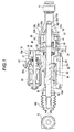
- a housing 10 is supported by rear wheels (not illustrated) of a vehicle via a first connection member 11 and a second connection member 12.
- the housing 10 accommodates an actuator configured to include an electric motor 20, a belt type speed reduction mechanism 30, a planetary gear mechanism 40, and a linear motion mechanism 50.
- the housing 10 in the embodiment is configured to include a body portion 10a of the housing; a tubular support portion 10b that is formed integrally with the first connection member 11; and a cover 10c that blocks an opening formed in the body portion 10a.
- a rubber boot RB is mounted between the body portion 10a and the second connection member 12.
- the body portion 10a supports the electric motor 20, and accommodates the belt type speed reduction mechanism 30.
- the support portion 10b accommodates the planetary gear mechanism 40 and the linear motion mechanism 50.
- a rod 52 of the linear motion mechanism 50 is supported by the body portion 10a.
- One end portion of the rod 52 extends out from the body portion 10a, and is connected to the second connection member 12.
- a single side expansion and contraction type actuator is configured to be capable of steering the rear wheels by increasing and decreasing the distance between the first connection member 11 and the second connection member 12 via expansion and contraction of the rod 52, which will be described later.
- a feed screw mechanism is disposed such that a male screw portion 52c, which has trapezoidal screws and is formed in an outer circumferential surface of the other end portion of the rod 52 across a predetermined axial length, is screwed to a female screw portion 51c formed in an inner circumferential surface of a nut member 51.
- the screw type is not limited to a trapezoidal screw, and a ball screw or the like may be used.
- the nut member 51 and the rod 52 form the linear motion mechanism 50, and the linear motion mechanism 50 converts rotational motion of the nut member 51 into linear motion of the rod 52.
- a support structure for supporting the nut member 51 and the rod 52 via the housing 10 will be described later.
- an output shaft 21 is rotatably supported by an attachment portion 20a joined to the body portion 10a of the housing 10, and a tip portion of the output shaft 21 extending out from the inside of the body portion 10a is connected to a drive pulley 31 of the belt type speed reduction mechanism 30.
- the electric motor 20 in the embodiment includes a brush 22, and may be a brushless motor.
- the belt type speed reduction mechanism 30 in the embodiment includes the drive pulley 31 that is connected to the output shaft 21 of the electric motor 20; a driven pulley 32 which is connected to the nut member 51 and is supported by the housing 10 such that the driven pulley 32 can be rotated around the axis of the rod 52; and a belt 33 that is provided in a tensed state between the driven pulley 32 and the drive pulley 31.
- the belt type speed reduction mechanism 30 in the embodiment includes the drive pulley 31 that is connected to the output shaft 21 of the electric motor 20; a driven pulley 32 which is connected to the nut member 51 and is supported by the housing 10 such that the driven pulley 32 can be rotated around the axis of the rod 52; and a belt 33 that is provided in a tensed state between the driven pulley 32 and the drive pulley 31.
- the driven pulley 32 has a hollow shape, is disposed coaxially with the rod 52, and is rotatably supported by the body portion 10a of the housing 10 via a bearing 34. External teeth are formed in each of the driven pulley 32 and the drive pulley 31, and internal teeth are formed in the belt 33.
- the driven pulley 32, the drive pulley 31, and the belt 33 are disposed such that both the external teeth and the internal teeth mesh with each other.
- the planetary gear mechanism 40 is mounted between the belt type speed reduction mechanism 30 and the linear motion mechanism 50.
- the planetary gear mechanism 40 is configured such that the speed of an output of the belt type speed reduction mechanism 30 is reduced and the reduced output is transmitted to the linear motion mechanism 50.
- the planetary gear mechanism 40 is configured to include a ring gear 41 that is non-rotatably supported inside of the housing 10; a sun gear 42 that is rotated integrally with the driven pulley 32; a planetary gear 43 that meshes with the ring gear 41 and the sun gear 42; and a pin 44 that rotatably supports the planetary gear 43 and is fixed to the nut member 51.
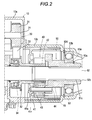
- the pin 44 and the like will be described in detail later with reference to Figs. 2 to 4 .
- the sun gear 42 in the embodiment is formed integrally with a shaft portion of the driven pulley 32; however, the sun gear 42 may be formed as a separate member, and be joined to the shaft portion of the driven pulley 32 such that the sun gear 42 is rotated integrally with the driven pulley 32.
- the nut member 51 of the linear motion mechanism 50 is rotatably supported by the support portion 10b of the housing 10 via a bearing 53.
- the nut member 51 supports the planetary gear 43 such that the planetary gear 43 can be rotated around the pin 44, and the nut member 51 serves as a carrier.
- the bearing 53 is a ball bearing.
- An inner race 53a of the bearing 53 is fitted to an outer circumferential surface of the nut member 51, and is held by a C-shaped snap ring 53c.
- An outer race 53b of the bearing 53 is fitted to an inner circumferential surface of the support portion 10b, and is held by a C-shaped snap ring 53d.
- the rod 52 is supported by the body portion 10a of the housing 10 via a pair of bushes B such that the rod can be moved (and cannot be rotated) in an axial direction.
- An axial load applied to the rod 52 is absorbed by the housing 10 via the nut member 51, the bearing 53, and the snap rings 53c and 53d.
- a nut 52d for preventing falling off of components is screwed to a tip of the male screw portion 52c of the rod 52, and a magnetic member 62 is screw-fixed to an intermediate portion of the rod 52.
- the magnetic member 62 is close to a displacement sensor 61, and is accommodated in the body portion 10a of the housing 10.
- the displacement sensor 61 is supported by an electronic circuit substrate 63, and forms an electronic control device 60.
- the magnetic member 62 has a function of detecting an axial displacement of the rod 52 during linear motion of the rod 52, and a function of preventing rotation of the rod 52 via contact with an inner surface of the body portion 10a.
- the speed of a rotational output of the electric motor 20 is reduced by the belt type speed reduction mechanism 30 and the planetary gear mechanism 40, the nut member 51 is driven and rotated, and rotational motion of the nut member 51 is converted into linear motion of the rod 52 by the linear motion mechanism 50. Accordingly, the distance between the first connection member 11 and the second connection member 12 is increased and decreased such that a steering angle of the rear wheels is adjusted.
- the planetary gear mechanism 40 in the embodiment includes the columnar pin 44 that rotatably supports the planetary gear 43 and is fixed to the nut member 51, and a partition wall portion 41s that separates the driven pulley 32 from the planetary gear 43 and prevents the planetary gear 43 from being axially moved a predetermined distance or longer.
- the partition wall portion 41s is formed integrally with the ring gear 41, includes an annular recessed portion 41r around the axis of the rod 52 which is formed in a surface of the partition wall portion 41s which faces the planetary gear 43, and is disposed such that a tip portion of the pin 44 is freely fitted into the recessed portion 41 r.
- the partition wall portion 41s is capable of reliably preventing infiltration of grease from the inside of the planetary gear mechanism 40 to the belt type speed reduction mechanism 30.
- the partition wall portion 41s may be formed separately from the ring gear 41.
- an axial distance (d) of the pin 44 between a side surface 41p of the partition wall portion 41s, which faces the planetary gear 43, and an end surface of the tip portion of the pin 44 is set to be larger than a gap (c) between the side surface 41 p and the planetary gear 43 (d > c).
- the planetary gear 43 including end surfaces is reliably supported by the pin 44, and the partition wall portion 41s prevents the planetary gear 43 from falling off from the pin 44.
- the partition wall portion 41s serves as a retainer which prevents axial movement of the planetary gear 43.
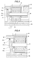
- the partition wall portion 41s includes an opening 41 q into which a shaft portion of the driven pulley 32 (formed integrally with the sun gear 42) is inserted. As ascertained from Fig. 3 , there is a void between the opening 41 q and the driven pulley 32; however, there is a low possibility of infiltration of grease to the belt type speed reduction mechanism 30 via the void.
- a seal member 45 may be mounted between the opening 41 q of the partition wall portion 41s and the driven pulley 32 so as to block the void. An O-ring illustrated in Fig. 4 or a so-called dust seal may be used as the seal member 45.
- the belt type speed reduction mechanism 30 it is possible to properly select and replace the drive pulley 31 and the belt 33, and it is possible to provide a rear wheel steering apparatus having different output characteristics by chaining the drive pulley 31 and the belt 33. That is, since the reduction gear ratio of the belt type speed reduction mechanism 30 is determined by a ratio in the number of teeth between the drive pulley 31 and the driven pulley 32, it is possible to change the reduction gear ratio by changing the number of teeth of the drive pulley 31 and the number of teeth of the belt 33 in a state where the axis-to-axis pitch between the output shaft 21 of the electric motor 20 and the rod 52 is fixed.
- a high-thrust rear wheel steering apparatus it is possible to build a high-thrust rear wheel steering apparatus by using a drive pulley 31x having a diameter smaller than that of the drive pulley 31 in Fig. 1 , and a belt 33x adapted for the drive pulley 31x while maintaining the same driven pulley 32 in Fig. 1 .
- a high-speed rear wheel steering apparatus by using a drive pulley 31 y having a diameter larger than that of the drive pulley 31 in Fig. 1 , and a belt 33y adapted for the drive pulley 31y.
- Other configuration components are common between the examples illustrated in Figs.
- Fig. 7 is a graph illustrating the output characteristics of the actuator that is formed of the electric motor 20, the belt type speed reduction mechanism 30, the planetary gear mechanism 40, and the linear motion mechanism 50.
- the horizontal axis represents thrust of the rod 52, and the vertical axis represents speed.
- the maximum output (P) of the actuator is calculated as the product of the maximum thrust (F) and a speed (V) at the maximum thrust. Since the electric motor 20, the planetary gear mechanism 40, and the linear motion mechanism 50 are common between the examples illustrated in Figs.
- the maximum output of the actuator is not dependent on the reduction gear ratio of the belt type speed reduction mechanism 30 and is substantially constant (strictly speaking, there is a slight difference in a belt transmission efficiency due to a difference in the reduction gear ratio, or there is a slight difference in a feed screw efficiency due to a difference in input torque or a rotational speed). It is possible to change the output characteristics while maintaining the maximum output in the constant range.
- the output characteristics of the actuator are not limited to P1 and P2, and it is possible to arbitrarily set the output characteristics in a range in which an output Px is equal to P (constant) by setting the reduction gear ratio of the belt type speed reduction mechanism 30.
- first connection member 11 is formed integrally with the support portion 10b of the housing 10, and the second connection member 12 is connected to the rod 52.
- second connection member 12 is connected to the rod 52.
- first and second connection members ball joints BJ. That is, since as described above, the driven pulley 32 has a hollow shape, the rod 52 is coaxially disposed inside the driven pulley 32, and the electric motor 20, the belt type speed reduction mechanism 30, the planetary gear mechanism 40, and the linear motion mechanism 50 can become common (it is necessary to slightly change the rod 52), as illustrated in Fig. 8 , it is possible to build a double side expansion and contraction type actuator with the minimum component change.
- a rod 52x extends out from both right and left sides of a housing 10x, and both end portions of the rod 52x are respectively connected to the ball joints BJ.
- a body portion 10ax and a support portion 10bx of the housing 10x are fixed to a vehicle frame (not illustrated) via brackets BK.
- One end portion of the rod 52x is supported by the body portion 10ax such that the rod 52x can be moved in an axial direction.
- a coupling member 54 through which the other end portion of the rod 52x is connected to the ball joint BJ, is supported by the support portion 10bx such that the coupling member 54 can be moved in the axial direction. Since other configuration elements are the same as those in the embodiment illustrated in Fig. 1 , the same reference signs as in Fig. 1 are assigned to substantially the same configuration elements, and description thereof will be omitted.
- the housing 10x, the bracket BK, and the like related to a support structure of these components with respect to the vehicle frame are different from those in the embodiment illustrated in Fig. 1 , and in contrast, the electric motor 20, the belt type speed reduction mechanism 30, the planetary gear mechanism 40, and the linear motion mechanism 50 (excluding the rod 52x) can become common.
- the electric motor 20, the belt type speed reduction mechanism 30, the planetary gear mechanism 40, and the linear motion mechanism 50 can become common.
- a vehicle rear wheel steering apparatus includes: a housing (10, 10x) supported by the rear wheels via first and second connection members (11, 12); an electric motor (20) supported by the housing; a speed reduction mechanism (30) connected to an output shaft (21) of the electric motor, and reducing the speed of an output of the electric motor; and a linear motion mechanism (50) including a nut member (51) connected to the speed reduction mechanism, and a rod (52) screwed to the nut member and connected to at least one of the first and second connection members, and converting rotational motion of the nut member into linear motion of the rod, wherein the speed reduction mechanism includes a planetary gear mechanism, and the speed of an output of the electric motor is reduced and the reduced output is transmitted to the linear motion mechanism.
Landscapes
- Engineering & Computer Science (AREA)
- Mechanical Engineering (AREA)
- Chemical & Material Sciences (AREA)
- Combustion & Propulsion (AREA)
- Transportation (AREA)
- General Engineering & Computer Science (AREA)
- Power Steering Mechanism (AREA)
- Steering-Linkage Mechanisms And Four-Wheel Steering (AREA)
- Retarders (AREA)
- Transmission Devices (AREA)
- Connection Of Motors, Electrical Generators, Mechanical Devices, And The Like (AREA)
Applications Claiming Priority (1)
| Application Number | Priority Date | Filing Date | Title |
|---|---|---|---|
| JP2015086373A JP2016203758A (ja) | 2015-04-21 | 2015-04-21 | 車両の後輪操舵装置 |
Publications (2)
| Publication Number | Publication Date |
|---|---|
| EP3085604A1 true EP3085604A1 (de) | 2016-10-26 |
| EP3085604B1 EP3085604B1 (de) | 2017-08-30 |
Family
ID=55745695
Family Applications (1)
| Application Number | Title | Priority Date | Filing Date |
|---|---|---|---|
| EP16165026.2A Not-in-force EP3085604B1 (de) | 2015-04-21 | 2016-04-13 | Hinterradlenkvorrichtung eines fahrzeugs |
Country Status (3)
| Country | Link |
|---|---|
| US (1) | US9567000B2 (de) |
| EP (1) | EP3085604B1 (de) |
| JP (1) | JP2016203758A (de) |
Cited By (1)
| Publication number | Priority date | Publication date | Assignee | Title |
|---|---|---|---|---|
| CN107725705A (zh) * | 2017-09-30 | 2018-02-23 | 北京精密机电控制设备研究所 | 一种直线式防卡塞双余度机电作动器 |
Families Citing this family (8)
| Publication number | Priority date | Publication date | Assignee | Title |
|---|---|---|---|---|
| DE102017205666B4 (de) * | 2016-05-25 | 2024-06-27 | Zf Friedrichshafen Ag | Lenkung mit einer Stelleinrichtung sowie Verwendung der Lenkung mit Stelleinrichtung |
| US10836421B2 (en) * | 2017-06-12 | 2020-11-17 | Steering Solutions Ip Holding Corporation | Steering system |
| US11247717B2 (en) * | 2018-05-11 | 2022-02-15 | Ford Global Technologies, Llc | Electric power assist steering assembly |
| DE102019112480B3 (de) * | 2019-05-13 | 2020-02-20 | Schaeffler Technologies AG & Co. KG | Fahrwerksaktuator und Verfahren zum Betrieb einer Getriebeanordnung eines Fahrwerksaktuators |
| CN110733563A (zh) * | 2019-11-18 | 2020-01-31 | 沙市久隆汽车动力转向器有限公司 | 一种电动循环球转向器 |
| DE102020130257B4 (de) * | 2020-09-29 | 2022-09-01 | Schaeffler Technologies AG & Co. KG | Aktuator einer Lenkung eines Kraftfahrzeuges |
| JP7723344B2 (ja) * | 2021-09-02 | 2025-08-14 | 株式会社アイシン | 遊星歯車機構 |
| CN116767341A (zh) * | 2023-08-08 | 2023-09-19 | 株洲易力达机电有限公司 | 一种后轮主动转向系统总成 |
Citations (3)
| Publication number | Priority date | Publication date | Assignee | Title |
|---|---|---|---|---|
| JPH07215226A (ja) | 1994-01-31 | 1995-08-15 | Aisin Seiki Co Ltd | 後輪操舵アクチュエ−タ |
| DE102007035004A1 (de) * | 2006-07-26 | 2008-02-21 | Aisin Seiki K.K., Kariya | Radlenkvorrichtung |
| EP1939019A1 (de) * | 2006-12-27 | 2008-07-02 | HONDA MOTOR CO., Ltd. | Teleskopischer Stellantrieb |
Family Cites Families (12)
| Publication number | Priority date | Publication date | Assignee | Title |
|---|---|---|---|---|
| JPS62198566A (ja) * | 1986-02-25 | 1987-09-02 | Honda Motor Co Ltd | ステアリング装置の中位位置復帰装置 |
| US5086861A (en) * | 1990-04-06 | 1992-02-11 | Peterson Donald W | Electric rear wheel steering actuator |
| JP2002067987A (ja) * | 2000-08-24 | 2002-03-08 | Aisin Seiki Co Ltd | 車両の操舵装置 |
| JP2005170168A (ja) * | 2003-12-10 | 2005-06-30 | Ntn Corp | 操舵軸進退駆動装置 |
| US20070151794A1 (en) * | 2004-12-28 | 2007-07-05 | Nsk Ltd. | Electric power steering apparatus |
| DE102006020041A1 (de) * | 2005-05-02 | 2007-03-15 | Continental Teves Ag & Co. Ohg | Lenkvorrichtung, insbesondere für eine Hinterradlenkung |
| JP4464955B2 (ja) * | 2006-12-27 | 2010-05-19 | 本田技研工業株式会社 | 伸縮アクチュエータ |
| JP4751315B2 (ja) * | 2006-12-29 | 2011-08-17 | 本田技研工業株式会社 | 伸縮アクチュエータ |
| JP4810474B2 (ja) * | 2007-03-16 | 2011-11-09 | 本田技研工業株式会社 | アクチュエータ付き車両 |
| DE102008059745A1 (de) * | 2008-12-01 | 2010-06-02 | Thyssenkrupp Presta Ag | Elektromechanische Servolenkung mit Kugelgewindetrieb |
| DE102009039164A1 (de) * | 2008-12-09 | 2010-06-10 | Continental Teves Ag & Co. Ohg | Lenkvorrichtung, insbesondere für eine Hinterradlenkung |
| CN104210544B (zh) * | 2013-05-29 | 2018-01-23 | 爱信精机株式会社 | 车辆的后轮转向装置 |
-
2015
- 2015-04-21 JP JP2015086373A patent/JP2016203758A/ja active Pending
-
2016
- 2016-04-13 EP EP16165026.2A patent/EP3085604B1/de not_active Not-in-force
- 2016-04-21 US US15/135,104 patent/US9567000B2/en not_active Expired - Fee Related
Patent Citations (6)
| Publication number | Priority date | Publication date | Assignee | Title |
|---|---|---|---|---|
| JPH07215226A (ja) | 1994-01-31 | 1995-08-15 | Aisin Seiki Co Ltd | 後輪操舵アクチュエ−タ |
| EP0667279A1 (de) * | 1994-01-31 | 1995-08-16 | Aisin Seiki Kabushiki Kaisha | Stellantrieb zum Lenken der Hinterräder |
| DE102007035004A1 (de) * | 2006-07-26 | 2008-02-21 | Aisin Seiki K.K., Kariya | Radlenkvorrichtung |
| JP5098242B2 (ja) | 2006-07-26 | 2012-12-12 | アイシン精機株式会社 | 車輪操舵装置 |
| EP1939019A1 (de) * | 2006-12-27 | 2008-07-02 | HONDA MOTOR CO., Ltd. | Teleskopischer Stellantrieb |
| JP2008164014A (ja) | 2006-12-27 | 2008-07-17 | Honda Motor Co Ltd | 伸縮アクチュエータ |
Cited By (2)
| Publication number | Priority date | Publication date | Assignee | Title |
|---|---|---|---|---|
| CN107725705A (zh) * | 2017-09-30 | 2018-02-23 | 北京精密机电控制设备研究所 | 一种直线式防卡塞双余度机电作动器 |
| CN107725705B (zh) * | 2017-09-30 | 2020-06-09 | 北京精密机电控制设备研究所 | 一种直线式防卡塞双余度机电作动器 |
Also Published As
| Publication number | Publication date |
|---|---|
| US9567000B2 (en) | 2017-02-14 |
| JP2016203758A (ja) | 2016-12-08 |
| US20160311463A1 (en) | 2016-10-27 |
| EP3085604B1 (de) | 2017-08-30 |
Similar Documents
| Publication | Publication Date | Title |
|---|---|---|
| EP3085604B1 (de) | Hinterradlenkvorrichtung eines fahrzeugs | |
| US9022890B2 (en) | Transmission device, for example for an electric axle and electric axle comprising the transmission device | |
| EP2764959B1 (de) | Gelenkmechanismus und Roboter | |
| JP6752687B2 (ja) | 電動アクチュエータ | |
| KR101611586B1 (ko) | 동심 다축 액추에이터 | |
| US9334928B2 (en) | Planetary gear apparatus | |
| US20160297465A1 (en) | Steering spline telescoping shaft, and steering device | |
| KR101399792B1 (ko) | 유성 기어 장치 | |
| US20100084214A1 (en) | Vehicle steering system | |
| US20180186398A1 (en) | Steering device | |
| JP5989148B2 (ja) | 減速機、及びこれを具えた直交型ギアモータ | |
| CN107406147A (zh) | 具有两条中间传动线路的减速器 | |
| US20030236146A1 (en) | Single planet steering position planetary differential | |
| US11293524B2 (en) | Vehicle drive device | |
| JP2006069518A (ja) | 電動式パワーステアリング装置 | |
| CN105317938B (zh) | 用于车辆转向装置的行星齿轮减速器 | |
| EP3012174A1 (de) | Hinterradlenkvorrichtung eines fahrzeugs | |
| WO2011078009A1 (ja) | 電動リニアアクチュエータ | |
| KR20140061016A (ko) | 유성 기어 장치 | |
| JP4473047B2 (ja) | 電動パワーステアリング装置 | |
| KR101705018B1 (ko) | 이송기능을 갖는 베벨감속기 및 이를 이용한 이송장치 | |
| EP2733045A2 (de) | Vorrichtung mit variablem Übersetzungsverhältnis | |
| CN110450849B (zh) | 一种转向装置、转向系统及自动驾驶车 | |
| JP2005321000A (ja) | 歯車の軸線位置を自動補正する歯車装置 | |
| IT202200020739A1 (it) | Trasmissione meccanica rotativa |
Legal Events
| Date | Code | Title | Description |
|---|---|---|---|
| PUAI | Public reference made under article 153(3) epc to a published international application that has entered the european phase |
Free format text: ORIGINAL CODE: 0009012 |
|
| AK | Designated contracting states |
Kind code of ref document: A1 Designated state(s): AL AT BE BG CH CY CZ DE DK EE ES FI FR GB GR HR HU IE IS IT LI LT LU LV MC MK MT NL NO PL PT RO RS SE SI SK SM TR |
|
| AX | Request for extension of the european patent |
Extension state: BA ME |
|
| 17P | Request for examination filed |
Effective date: 20161130 |
|
| RBV | Designated contracting states (corrected) |
Designated state(s): AL AT BE BG CH CY CZ DE DK EE ES FI FR GB GR HR HU IE IS IT LI LT LU LV MC MK MT NL NO PL PT RO RS SE SI SK SM TR |
|
| GRAJ | Information related to disapproval of communication of intention to grant by the applicant or resumption of examination proceedings by the epo deleted |
Free format text: ORIGINAL CODE: EPIDOSDIGR1 |
|
| GRAP | Despatch of communication of intention to grant a patent |
Free format text: ORIGINAL CODE: EPIDOSNIGR1 |
|
| RIC1 | Information provided on ipc code assigned before grant |
Ipc: B62D 7/15 20060101ALI20170322BHEP Ipc: B62D 7/14 20060101AFI20170322BHEP |
|
| INTG | Intention to grant announced |
Effective date: 20170421 |
|
| GRAS | Grant fee paid |
Free format text: ORIGINAL CODE: EPIDOSNIGR3 |
|
| GRAA | (expected) grant |
Free format text: ORIGINAL CODE: 0009210 |
|
| AK | Designated contracting states |
Kind code of ref document: B1 Designated state(s): AL AT BE BG CH CY CZ DE DK EE ES FI FR GB GR HR HU IE IS IT LI LT LU LV MC MK MT NL NO PL PT RO RS SE SI SK SM TR |
|
| REG | Reference to a national code |
Ref country code: GB Ref legal event code: FG4D |
|
| REG | Reference to a national code |
Ref country code: CH Ref legal event code: EP |
|
| REG | Reference to a national code |
Ref country code: AT Ref legal event code: REF Ref document number: 923233 Country of ref document: AT Kind code of ref document: T Effective date: 20170915 |
|
| REG | Reference to a national code |
Ref country code: IE Ref legal event code: FG4D |
|
| REG | Reference to a national code |
Ref country code: DE Ref legal event code: R096 Ref document number: 602016000313 Country of ref document: DE |
|
| REG | Reference to a national code |
Ref country code: NL Ref legal event code: MP Effective date: 20170830 |
|
| REG | Reference to a national code |
Ref country code: LT Ref legal event code: MG4D |
|
| REG | Reference to a national code |
Ref country code: AT Ref legal event code: MK05 Ref document number: 923233 Country of ref document: AT Kind code of ref document: T Effective date: 20170830 |
|
| PG25 | Lapsed in a contracting state [announced via postgrant information from national office to epo] |
Ref country code: NO Free format text: LAPSE BECAUSE OF FAILURE TO SUBMIT A TRANSLATION OF THE DESCRIPTION OR TO PAY THE FEE WITHIN THE PRESCRIBED TIME-LIMIT Effective date: 20171130 Ref country code: HR Free format text: LAPSE BECAUSE OF FAILURE TO SUBMIT A TRANSLATION OF THE DESCRIPTION OR TO PAY THE FEE WITHIN THE PRESCRIBED TIME-LIMIT Effective date: 20170830 Ref country code: AT Free format text: LAPSE BECAUSE OF FAILURE TO SUBMIT A TRANSLATION OF THE DESCRIPTION OR TO PAY THE FEE WITHIN THE PRESCRIBED TIME-LIMIT Effective date: 20170830 Ref country code: SE Free format text: LAPSE BECAUSE OF FAILURE TO SUBMIT A TRANSLATION OF THE DESCRIPTION OR TO PAY THE FEE WITHIN THE PRESCRIBED TIME-LIMIT Effective date: 20170830 Ref country code: FI Free format text: LAPSE BECAUSE OF FAILURE TO SUBMIT A TRANSLATION OF THE DESCRIPTION OR TO PAY THE FEE WITHIN THE PRESCRIBED TIME-LIMIT Effective date: 20170830 Ref country code: LT Free format text: LAPSE BECAUSE OF FAILURE TO SUBMIT A TRANSLATION OF THE DESCRIPTION OR TO PAY THE FEE WITHIN THE PRESCRIBED TIME-LIMIT Effective date: 20170830 |
|
| PG25 | Lapsed in a contracting state [announced via postgrant information from national office to epo] |
Ref country code: RS Free format text: LAPSE BECAUSE OF FAILURE TO SUBMIT A TRANSLATION OF THE DESCRIPTION OR TO PAY THE FEE WITHIN THE PRESCRIBED TIME-LIMIT Effective date: 20170830 Ref country code: BG Free format text: LAPSE BECAUSE OF FAILURE TO SUBMIT A TRANSLATION OF THE DESCRIPTION OR TO PAY THE FEE WITHIN THE PRESCRIBED TIME-LIMIT Effective date: 20171130 Ref country code: IS Free format text: LAPSE BECAUSE OF FAILURE TO SUBMIT A TRANSLATION OF THE DESCRIPTION OR TO PAY THE FEE WITHIN THE PRESCRIBED TIME-LIMIT Effective date: 20171230 Ref country code: GR Free format text: LAPSE BECAUSE OF FAILURE TO SUBMIT A TRANSLATION OF THE DESCRIPTION OR TO PAY THE FEE WITHIN THE PRESCRIBED TIME-LIMIT Effective date: 20171201 Ref country code: LV Free format text: LAPSE BECAUSE OF FAILURE TO SUBMIT A TRANSLATION OF THE DESCRIPTION OR TO PAY THE FEE WITHIN THE PRESCRIBED TIME-LIMIT Effective date: 20170830 Ref country code: ES Free format text: LAPSE BECAUSE OF FAILURE TO SUBMIT A TRANSLATION OF THE DESCRIPTION OR TO PAY THE FEE WITHIN THE PRESCRIBED TIME-LIMIT Effective date: 20170830 |
|
| REG | Reference to a national code |
Ref country code: FR Ref legal event code: PLFP Year of fee payment: 3 |
|
| PG25 | Lapsed in a contracting state [announced via postgrant information from national office to epo] |
Ref country code: NL Free format text: LAPSE BECAUSE OF FAILURE TO SUBMIT A TRANSLATION OF THE DESCRIPTION OR TO PAY THE FEE WITHIN THE PRESCRIBED TIME-LIMIT Effective date: 20170830 |
|
| PG25 | Lapsed in a contracting state [announced via postgrant information from national office to epo] |
Ref country code: DK Free format text: LAPSE BECAUSE OF FAILURE TO SUBMIT A TRANSLATION OF THE DESCRIPTION OR TO PAY THE FEE WITHIN THE PRESCRIBED TIME-LIMIT Effective date: 20170830 Ref country code: PL Free format text: LAPSE BECAUSE OF FAILURE TO SUBMIT A TRANSLATION OF THE DESCRIPTION OR TO PAY THE FEE WITHIN THE PRESCRIBED TIME-LIMIT Effective date: 20170830 Ref country code: CZ Free format text: LAPSE BECAUSE OF FAILURE TO SUBMIT A TRANSLATION OF THE DESCRIPTION OR TO PAY THE FEE WITHIN THE PRESCRIBED TIME-LIMIT Effective date: 20170830 |
|
| PG25 | Lapsed in a contracting state [announced via postgrant information from national office to epo] |
Ref country code: IT Free format text: LAPSE BECAUSE OF FAILURE TO SUBMIT A TRANSLATION OF THE DESCRIPTION OR TO PAY THE FEE WITHIN THE PRESCRIBED TIME-LIMIT Effective date: 20170830 Ref country code: EE Free format text: LAPSE BECAUSE OF FAILURE TO SUBMIT A TRANSLATION OF THE DESCRIPTION OR TO PAY THE FEE WITHIN THE PRESCRIBED TIME-LIMIT Effective date: 20170830 Ref country code: SK Free format text: LAPSE BECAUSE OF FAILURE TO SUBMIT A TRANSLATION OF THE DESCRIPTION OR TO PAY THE FEE WITHIN THE PRESCRIBED TIME-LIMIT Effective date: 20170830 Ref country code: SM Free format text: LAPSE BECAUSE OF FAILURE TO SUBMIT A TRANSLATION OF THE DESCRIPTION OR TO PAY THE FEE WITHIN THE PRESCRIBED TIME-LIMIT Effective date: 20170830 |
|
| REG | Reference to a national code |
Ref country code: DE Ref legal event code: R097 Ref document number: 602016000313 Country of ref document: DE |
|
| PLBE | No opposition filed within time limit |
Free format text: ORIGINAL CODE: 0009261 |
|
| STAA | Information on the status of an ep patent application or granted ep patent |
Free format text: STATUS: NO OPPOSITION FILED WITHIN TIME LIMIT |
|
| PGFP | Annual fee paid to national office [announced via postgrant information from national office to epo] |
Ref country code: DE Payment date: 20180404 Year of fee payment: 3 |
|
| 26N | No opposition filed |
Effective date: 20180531 |
|
| PG25 | Lapsed in a contracting state [announced via postgrant information from national office to epo] |
Ref country code: SI Free format text: LAPSE BECAUSE OF FAILURE TO SUBMIT A TRANSLATION OF THE DESCRIPTION OR TO PAY THE FEE WITHIN THE PRESCRIBED TIME-LIMIT Effective date: 20170830 |
|
| PG25 | Lapsed in a contracting state [announced via postgrant information from national office to epo] |
Ref country code: MC Free format text: LAPSE BECAUSE OF FAILURE TO SUBMIT A TRANSLATION OF THE DESCRIPTION OR TO PAY THE FEE WITHIN THE PRESCRIBED TIME-LIMIT Effective date: 20170830 |
|
| REG | Reference to a national code |
Ref country code: BE Ref legal event code: MM Effective date: 20180430 |
|
| REG | Reference to a national code |
Ref country code: IE Ref legal event code: MM4A |
|
| PG25 | Lapsed in a contracting state [announced via postgrant information from national office to epo] |
Ref country code: LU Free format text: LAPSE BECAUSE OF NON-PAYMENT OF DUE FEES Effective date: 20180413 |
|
| PG25 | Lapsed in a contracting state [announced via postgrant information from national office to epo] |
Ref country code: BE Free format text: LAPSE BECAUSE OF NON-PAYMENT OF DUE FEES Effective date: 20180430 |
|
| PG25 | Lapsed in a contracting state [announced via postgrant information from national office to epo] |
Ref country code: IE Free format text: LAPSE BECAUSE OF NON-PAYMENT OF DUE FEES Effective date: 20180413 |
|
| PGFP | Annual fee paid to national office [announced via postgrant information from national office to epo] |
Ref country code: FR Payment date: 20190313 Year of fee payment: 4 |
|
| REG | Reference to a national code |
Ref country code: DE Ref legal event code: R119 Ref document number: 602016000313 Country of ref document: DE |
|
| REG | Reference to a national code |
Ref country code: CH Ref legal event code: PL |
|
| PG25 | Lapsed in a contracting state [announced via postgrant information from national office to epo] |
Ref country code: MT Free format text: LAPSE BECAUSE OF NON-PAYMENT OF DUE FEES Effective date: 20180413 Ref country code: DE Free format text: LAPSE BECAUSE OF NON-PAYMENT OF DUE FEES Effective date: 20191101 Ref country code: CH Free format text: LAPSE BECAUSE OF NON-PAYMENT OF DUE FEES Effective date: 20190430 Ref country code: LI Free format text: LAPSE BECAUSE OF NON-PAYMENT OF DUE FEES Effective date: 20190430 |
|
| PG25 | Lapsed in a contracting state [announced via postgrant information from national office to epo] |
Ref country code: TR Free format text: LAPSE BECAUSE OF FAILURE TO SUBMIT A TRANSLATION OF THE DESCRIPTION OR TO PAY THE FEE WITHIN THE PRESCRIBED TIME-LIMIT Effective date: 20170830 |
|
| PG25 | Lapsed in a contracting state [announced via postgrant information from national office to epo] |
Ref country code: PT Free format text: LAPSE BECAUSE OF FAILURE TO SUBMIT A TRANSLATION OF THE DESCRIPTION OR TO PAY THE FEE WITHIN THE PRESCRIBED TIME-LIMIT Effective date: 20170830 |
|
| PG25 | Lapsed in a contracting state [announced via postgrant information from national office to epo] |
Ref country code: HU Free format text: LAPSE BECAUSE OF FAILURE TO SUBMIT A TRANSLATION OF THE DESCRIPTION OR TO PAY THE FEE WITHIN THE PRESCRIBED TIME-LIMIT; INVALID AB INITIO Effective date: 20160413 Ref country code: CY Free format text: LAPSE BECAUSE OF FAILURE TO SUBMIT A TRANSLATION OF THE DESCRIPTION OR TO PAY THE FEE WITHIN THE PRESCRIBED TIME-LIMIT Effective date: 20170830 Ref country code: MK Free format text: LAPSE BECAUSE OF NON-PAYMENT OF DUE FEES Effective date: 20170830 Ref country code: RO Free format text: LAPSE BECAUSE OF FAILURE TO SUBMIT A TRANSLATION OF THE DESCRIPTION OR TO PAY THE FEE WITHIN THE PRESCRIBED TIME-LIMIT Effective date: 20170830 |
|
| PG25 | Lapsed in a contracting state [announced via postgrant information from national office to epo] |
Ref country code: AL Free format text: LAPSE BECAUSE OF FAILURE TO SUBMIT A TRANSLATION OF THE DESCRIPTION OR TO PAY THE FEE WITHIN THE PRESCRIBED TIME-LIMIT Effective date: 20170830 |
|
| PG25 | Lapsed in a contracting state [announced via postgrant information from national office to epo] |
Ref country code: FR Free format text: LAPSE BECAUSE OF NON-PAYMENT OF DUE FEES Effective date: 20200430 |
|
| GBPC | Gb: european patent ceased through non-payment of renewal fee |
Effective date: 20200413 |
|
| PG25 | Lapsed in a contracting state [announced via postgrant information from national office to epo] |
Ref country code: GB Free format text: LAPSE BECAUSE OF NON-PAYMENT OF DUE FEES Effective date: 20200413 |