EP3083372B1 - Agencement de carrosserie d'un véhicule automobile comprenant un obturateur latéral de grille d'auvent - Google Patents
Agencement de carrosserie d'un véhicule automobile comprenant un obturateur latéral de grille d'auvent Download PDFInfo
- Publication number
- EP3083372B1 EP3083372B1 EP14798912.3A EP14798912A EP3083372B1 EP 3083372 B1 EP3083372 B1 EP 3083372B1 EP 14798912 A EP14798912 A EP 14798912A EP 3083372 B1 EP3083372 B1 EP 3083372B1
- Authority
- EP
- European Patent Office
- Prior art keywords
- wing
- windscreen
- arrangement according
- side edge
- windshield
- Prior art date
- Legal status (The legal status is an assumption and is not a legal conclusion. Google has not performed a legal analysis and makes no representation as to the accuracy of the status listed.)
- Not-in-force
Links
Images
Classifications
-
- B—PERFORMING OPERATIONS; TRANSPORTING
- B62—LAND VEHICLES FOR TRAVELLING OTHERWISE THAN ON RAILS
- B62D—MOTOR VEHICLES; TRAILERS
- B62D25/00—Superstructure or monocoque structure sub-units; Parts or details thereof not otherwise provided for
- B62D25/08—Front or rear portions
- B62D25/081—Cowls
-
- B—PERFORMING OPERATIONS; TRANSPORTING
- B62—LAND VEHICLES FOR TRAVELLING OTHERWISE THAN ON RAILS
- B62D—MOTOR VEHICLES; TRAILERS
- B62D25/00—Superstructure or monocoque structure sub-units; Parts or details thereof not otherwise provided for
- B62D25/08—Front or rear portions
-
- B—PERFORMING OPERATIONS; TRANSPORTING
- B62—LAND VEHICLES FOR TRAVELLING OTHERWISE THAN ON RAILS
- B62D—MOTOR VEHICLES; TRAILERS
- B62D23/00—Combined superstructure and frame, i.e. monocoque constructions
-
- B—PERFORMING OPERATIONS; TRANSPORTING
- B62—LAND VEHICLES FOR TRAVELLING OTHERWISE THAN ON RAILS
- B62D—MOTOR VEHICLES; TRAILERS
- B62D25/00—Superstructure or monocoque structure sub-units; Parts or details thereof not otherwise provided for
- B62D25/08—Front or rear portions
- B62D25/16—Mud-guards or wings; Wheel cover panels
Definitions
- the present invention relates to a bodywork arrangement of a motor vehicle, and more specifically to an arrangement in the lower side area of the windshield.
- the lower side area of the windshield comprises a bodywork part called "lateral shutter of awning grid” (or “OLGA"), this part being intended to close a space delimited on the one hand by the lateral edge of the windshield and on the other hand by the wing or the adjacent wing support.
- OLGA lateral shutter of awning grid
- the known arrangements are not completely satisfactory given the geometric dispersions of manufacture and assembly found in this area.
- the vehicle US 2013/076073 A1 describes such a known arrangement. From one vehicle to another, the transverse position of the windshield and the lower berry beam may vary a few millimeters relative to the wing and the wing support, because of these dispersions.
- the known lateral shutters are unsuited to these geometrical differences and themselves undergo dilations which can further degrade the games and / or stresses between the elements in this zone.
- this area is very visible from the outside, so that geometry defects in this area are highly detrimental to the quality perceived by the user of the vehicle.
- the object of the invention is to overcome all or part of the above disadvantages by proposing a lateral shutter which takes into account geometric dispersions. in the assembly of the elements in the presence and effects of expansion of the shutter itself.
- the invention also relates to a motor vehicle comprising a bodywork arrangement having all or part of the preceding features.
- XYZ is conventionally used in which X designates the longitudinal front-to-rear direction of the vehicle, oriented towards the rear, Y the transverse direction, oriented towards the right of the vehicle, and Z the vertical direction. , facing up.
- the term “substantially” means in the remainder of the statement that a slight deviation is allowed around a certain nominal position or direction. For example “substantially vertical” must be understood in the sense or a variation of about 5 ° around the vertical position is within the scope of the invention.
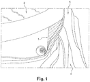
- FIG. 1 hatched a zone 1 of the bodywork arrangement according to the invention, located at the base and on a side edge of the windshield.
- a windshield 2 a lower cross member 3 (or "TIB") which extends along a lower edge of the windshield breeze 2 transversely to the vehicle, that is to say in the direction Y.
- the arrangement also comprises a wing 4 and a wing support 5.
- the wing support 5 is attached to the structure (not shown) of the vehicle.
- the wing 4 has an upper portion bent inwardly of the vehicle below an upper edge of the wing support 5 and fixed on an inner face thereof.
- the term "inside” means that the part or face is turned towards the engine compartment. It is noted that the upper edge of the wing support 5 and the drooping portion of the wing 4 which is fixed to the wing support 5 form a substantially vertical wall, disposed substantially in a lifetime screw of the lateral edge of the windshield. 2.
- a space E1, E2 measured in the transverse direction Y is formed between each wing 4 (and / or wing support 5) and an adjacent lateral edge 21 of the windshield 2.
- the bodywork arrangement according to the invention comprises a lateral shutter 6 (or "OLGA") closing said space E1, E2.
- the lateral shutter 6 has the general shape of a bracket whose lower branch 61 cooperates in contact with the lateral edge 21 of the windshield 2 and an upper branch 62 hooked on the adjacent wing 4.
- the lower branches 61 and upper 62 are connected by an angle portion 63 forming a hinge.
- This corner portion 62 is able to deform to absorb geometric dispersions and relative deformations on the one hand between the windshield 2 and the lower crossbar of the bay 3 and on the other hand between the wing 4 and the support 5.
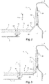
- FIG. figure 3 the geometrical dispersions of the windshield 2 and the lower crossbar of the bay 3 by the arrows F. These represent an offset in the transverse direction Y of the windshield 2 and the lower crossbar of the bay 3 relative to their position opposite, as illustrated in figure 2 .
- the Figures 2 and 3 represent the windshield 2 and the lower crossbeam in positions respectively remote and close to the wing 4 and the wing support.
- These geometric dispersions can be several millimeters from one vehicle to another.
- the space E1 is thus greater than the space E2 by a few millimeters.
- These positions are extreme positions, all vehicles produced and incorporating a bodywork arrangement according to the invention to have configurations located between these two extreme positions.
- the lower branch 61 opposes a resistant force on the side edge 21 of the windshield 2 applied towards the inside of the vehicle in the transverse direction Y. This force is also exerted upwards.
- the upper arm 62 is disposed in a slightly inclined manner against a substantially vertical face of the adjacent wing 4. The tilt is typically between 5 and 15 °.
- the upper branch 62 comprises at least one retaining lug 64 introduced into a corresponding hole of the flange 4 intended to hook the upper branch 62 to the flange 4.
- the upper branch 62 is hooked in its upper part.
- the upper branch 62 In the position shown in figure 3 (Position of the windshield 2 which is close to the wing 4 and the wing support 5), the upper branch 62 is disposed substantially parallel to the bearing face (inner wall above) of the wing 4 adjacent and wing support 5. The upper branch 62 is applied against this bearing face.
- the transition from a position as illustrated in figure 2 in a position as illustrated in figure 3 is effected by the elastic deformation of the corner portion 63 and the modification of the inclination of the upper branch 62 which passes a tilted position to a substantially vertical position.
- the transverse position of the lower branch 61 is thus modified, the latter being able as a function of the need and the geometric dispersions encountered to be placed at a distance or as close as possible to the wing 4 and the wing support 5.
- the lower branch 61 of the lateral shutter 6 has a recess 64 in which is placed the lateral edge 21 of the windshield 2.
- the latter and the lower branch 61 have substantially flush upper faces.
- the term "upper faces" in this case means that they are facing upwards.
- the recess 64 is shaped in a square shape at the edge of the lower branch 61 of the shutter 6.
- the bracket has a horizontal portion arranged to cover a corresponding lateral edge of the lower cross member 3.
- the branch lower 61 and the lower bay cross so partially overlap in a junction area.
- a portion of the edge of the lower branch 61 is interposed vertically between the lower crosspiece of the bay 3 and the windshield 2.
- the lower branch 61 is disposed substantially in the extension of the windshield 2, substantially parallel thereto.
- the elastic deformation located in the corner portion is achieved by the relative orientation between the two branches (substantially 90 °) and by a reduced thickness of this corner portion relative to the lower 61 and upper 62 branches.
- the lower branch 61 has a resistant force on the side edge 21 of the windshield 2.
- the lateral shutter 6 is under stress between the windshield 2 and the wing 4 associated with the wing support 5.
- the shutter 6 acts as a spring tending to resume its original configuration. It rests against the bearing face formed by the wing 4 and the wing support 5 so that the lower arm 61 is applied by contact against the side edge 21 of the windshield 2. No residual play is therefore lamented between the windshield 2 and the shutter 6, even if the windshield is in a position remote from the wing 4 and the wing support 5.
- this difference is compensated by the elastic deformation of the shutter 6 and the change of inclination of the upper branch 62.
Landscapes
- Engineering & Computer Science (AREA)
- Chemical & Material Sciences (AREA)
- Combustion & Propulsion (AREA)
- Transportation (AREA)
- Mechanical Engineering (AREA)
- Body Structure For Vehicles (AREA)
- Air-Conditioning For Vehicles (AREA)
Description
- La présente invention concerne un agencement de carrosserie d'un véhicule automobile, et plus précisément un agencement dans la zone latérale inférieure du pare-brise.
- De chaque côté du véhicule, on connaît des agencements dans lesquels la zone latérale inférieure du pare-brise comprend une pièce de carrosserie dénommée « obturateur latéral de grille d'auvent » (ou « OLGA »), cette pièce étant destinée à fermer un espace délimité d'une part par le bord latéral du pare-brise et d'autre part par l'aile ou le support d'aile adjacent.
Les agencements connus ne donnent pas complètement satisfaction compte tenu des dispersions géométriques de fabrication et d'assemblage constatées dans cette zone. Le véhiculeUS 2013/076073 A1 décrit un tel agencement connu. D'un véhicule à l'autre, la position transversale du pare-brise et de la traverse inférieure de baie peuvent varier de quelques millimètres par rapport à l'aile et au support d'aile, en raison de ces dispersions. Les obturateurs latéraux connus sont inadaptés à ces écarts géométriques et subissent eux même des dilatations qui peuvent encore dégrader les jeux et/ou contraintes entre les éléments dans cette zone. En outre cette zone est très visible de l'extérieur, de sorte que des défauts de géométrie dans cette zone sont fortement préjudiciables à la qualité perçue par l'utilisateur du véhicule. - L'invention a pour but de pallier tout ou partie des inconvénients précédents en proposant un obturateur latéral qui tienne compte des dispersions géométriques dans l'assemblage des éléments en présence et des effets de dilatations de l'obturateur lui-même.
- A cet effet, l'invention a pour objet un agencement de carrosserie d'un véhicule automobile comprenant un pare-brise, une traverse inférieure de baie s'étendant le long d'un bord inférieur du pare-brise et s'étendant transversalement au véhicule, une aile et un support d'aile étant disposés de chaque côté du véhicule de façon à encadrer la traverse inférieure de baie avec un espace ménagé entre chaque aile et un bord latéral adjacent du pare-brise, l'agencement comprenant un obturateur latéral fermant ledit espace, l'obturateur latéral ayant la forme générale d'une équerre, caractérisé en ce qu' une branche inférieure de l'équerre en contact avec le bord latéral du pare-brise et une branche supérieure est accrochée sur l'aile adjacente, les branches étant reliées par une partie d'angle formant charnière apte à se déformer pour absorber les dispersions géométriques et les déformations relatives entre d'une part le pare-brise et la traverse inférieure de baie et d'autre part l'aile et le support d'aile.
L'agencement de l'invention comprend donc un obturateur déformable élastiquement qui s'adapte parfaitement aux dispersions géométriques et permet de les compenser tout en fermant efficacement l'espace entre d'une part le bord latéral du pare-brise et d'autre part l'aile et le support d'aile. L'obturateur est également adaptatif en fonction des effets de dilatation.
Selon d'autres caractéristiques avantageuses de l'invention : - l'obturateur interposé entre le bord latéral du pare-brise et l'aile adjacente est déformé élastiquement et oppose un effort résistant sur le bord latéral du pare-brise appliqué vers l'intérieur du véhicule suivant la direction transversale et vers le haut,
- la branche inférieure de l'obturateur latéral comporte un renfoncement dans lequel est placé le bord latéral du pare-brise de façon que ce dernier et la branche inférieure présentent des faces supérieures sensiblement affleurantes,
- le renfoncement est conformé dans une forme en équerre bordant la branche inférieure de l'obturateur l'équerre ayant une partie horizontale disposée de façon à recouvrir un bord latéral correspondant de la traverse inférieure de baie,
- la branche inférieure est disposée sensiblement dans le prolongement du pare-brise, de façon sensiblement parallèle à celui-ci,
- la branche supérieure de l'obturateur latéral est disposée en appui contre une face sensiblement verticale de l'aile adjacente, la branche supérieure comprenant au moins une patte de retenue introduite dans un orifice correspondant de l'aile,
- la partie d'angle a une épaisseur réduite rapport aux branches inférieure et supérieure.
- L'invention a également pour objet un véhicule automobile comprenant un agencement de carrosserie ayant tout ou partie des caractéristiques précédentes.
- L'invention sera mieux comprise à la lecture de la description suivante d'un exemple non limitatif de l'invention, et à la lumière des dessins annexés sur lesquels :
- la
figure 1 représente en hachuré la zone de l'agencement de carrosserie selon l'invention, située à la base du pare-brise, entre un bord latéral de celui-ci et une aile adjacente du véhicule, - la
figure 2 représente l'agencement selon l'invention, dans une section schématique suivant un plan vertical ZY, dans lequel le pare-brise et la traverse inférieure de baie sont dans une position transversale éloignée de l'aile et du support d'aile associé, cette position résultant des dispersions géométriques de fabrication et de montage, et - la
figure 3 représente l'agencement de l'invention dans une section similaire à celle de lafigure 1 , cette section illustrant le pare-brise et la traverse inférieure de baie dans une position rapprochée de l'aile et du support d'aile associé, cette position résultant des dispersions géométriques de fabrication et de montage. - Dans l'ensemble de la description, on utilise classiquement le repère XYZ dans lequel X désigne la direction longitudinale avant-arrière du véhicule, orienté vers l'arrière, Y la direction transversale, orienté vers la droite du véhicule, et Z la direction verticale, orienté vers le haut.
Le terme « sensiblement » signifie dans la suite de l'exposé qu'un léger écart est admis autour d'une position ou d'une direction nominale déterminée. Par exemple « sensiblement vertical » doit être entendu au sens ou une variation de l'ordre de 5° autour de la position verticale est comprise dans le cadre de l'invention. - On a représenté à la
figure 1 en hachuré une zone 1 de l'agencement de carrosserie selon l'invention, située à la base et sur un bord latéral du pare-brise.
En référence auxfigures 2 et 3 qui illustrent plus en détail une section suivant YZ de cet agencement, on reconnait dans cette construction un pare-brise 2, une traverse inférieure de baie 3 (ou « TIB ») qui s'étend le long d'un bord inférieur du pare-brise 2 transversalement au véhicule, c'est-à-dire suivant la direction Y. L'agencement comprend également une aile 4 et un support d'aile 5. Le support d'aile 5 est fixé à la structure (non représentée) du véhicule. L'aile 4 comporte une partie supérieure recourbée vers l'intérieur du véhicule par-dessous une arête supérieure du support d'aile 5 et fixée sur une face intérieure de ce dernier. Le terme « intérieur » signifie que la pièce ou la face est tournée vers le compartiment moteur. On note que l'arête supérieure du support d'aile 5 et la partie retombante de l'aile 4 qui est fixée au support d'aile 5 forment une paroi sensiblement verticale, disposée sensiblement en vis à vie du bord latéral du pare-brise 2. Un espace E1, E2 mesuré suivant la direction transversale Y est ménagé entre chaque aile 4 (et/ou support d'aile 5) et un bord latéral 21 adjacent du pare-brise 2. L'agencement de carrosserie suivant l'invention comprend un obturateur latéral 6 (ou « OLGA ») fermant ledit espace E1, E2. L'obturateur latéral 6 a la forme générale d'une équerre dont une branche inférieure 61 coopère en contact avec le bord latéral 21 du pare-brise 2 et une branche supérieure 62 accrochée sur l'aile adjacente 4. - Les branches inférieures 61 et supérieure 62 sont reliées par une partie d'angle 63 formant charnière. Cette partie d'angle 62 est apte à se déformer pour absorber les dispersions géométriques et les déformations relatives d'une part entre le pare-brise 2 et la traverse inférieure de baie 3 et d'autre part entre l'aile 4 et le support d'aile 5. De façon schématique on a représenté à la
figure 3 les dispersions géométriques du pare-brise 2 et de la traverse inférieure de baie 3 par les flèches F. Celles-ci représentent un décalage suivant la direction transversale Y du pare-brise 2 et de la traverse inférieure de baie 3 par rapport à leur position opposée, telle qu'illustré à lafigure 2 . Lesfigures 2 et 3 représentent le pare-brise 2 et la traverse inférieure de baie dans des positions respectivement éloignée et rapprochée de l'aile 4 et du support d'aile. Ces dispersions géométriques peuvent être de plusieurs millimètres d'un véhicule à l'autre. L'espace E1 est ainsi supérieur à l'espace E2 de quelques millimètres. Ces positions sont des positions extrêmes, l'ensemble des véhicules produits et intégrant un agencement de carrosserie selon l'invention devant présenter des configurations situées entre ces deux positions extrêmes.
La branche inférieure 61 oppose un effort résistant sur le bord latéral 21 du pare-brise 2 appliqué vers l'intérieur du véhicule suivant la direction transversale Y. Cet effort s'exerce également vers le haut. Dans la position représentée à lafigure 2 (position du pare-brise 2 qui est éloignée de l'aile 4 et du support d'aile 5), la branche supérieure 62 est disposée en appui de façon légèrement inclinée contre une face sensiblement verticale de l'aile adjacente 4. L'inclinaison est typiquement comprise entre 5 et 15°. La branche supérieure 62 comprend au moins une patte de retenue 64 introduite dans un orifice correspondant de l'aile 4 destinée à accrocher la branche supérieure 62 à l'aile 4. La branche supérieure 62 est accrochée dans sa partie haute.
Dans la position représentée à lafigure 3 (position du pare-brise 2 qui est rapprochée de l'aile 4 et du support d'aile 5), la branche supérieure 62 est disposée de façon sensiblement parallèle à la face d'appui (paroi intérieure précitée) de l'aile 4 adjacente et du support d'aile 5. La branche supérieure 62 est appliquée contre cette face d'appui. - Le passage d'une position telle qu'illustrée à la
figure 2 à une position telle qu'illustrée à lafigure 3 est réalisée par la déformation élastique de la partie d'angle 63 et par la modification de l'inclinaison de la branche supérieure 62 qui passe une position penchée à une position sensiblement verticale. La position transversale de la branche inférieure 61 est ainsi modifiée, cette dernière pouvant en fonction du besoin et des dispersions géométriques rencontrées être placée à distance ou au plus près de l'aile 4 et du support d'aile 5.
La branche inférieure 61 de l'obturateur latéral 6 comporte un renfoncement 64 dans lequel est placé le bord latéral 21 du pare-brise 2. Ce dernier et la branche inférieure 61 présentent des faces supérieures sensiblement affleurantes. Le terme « faces supérieures » signifie en l'espèce qu'elles sont tournées vers le haut. - Le renfoncement 64 est conformé dans une forme en équerre situé au bord de la branche inférieure 61 de l'obturateur 6. L'équerre a une partie horizontale disposée de façon à recouvrir un bord latéral correspondant de la traverse inférieure de baie 3. La branche inférieure 61 et la traverse inférieure de baie se chevauchent donc partiellement, dans une zone de jonction. Une partie du bord de la branche inférieure 61 est intercalée verticalement entre la traverse inférieure de baie 3 et le pare-brise 2.
La branche inférieure 61 est disposée sensiblement dans le prolongement du pare-brise 2, de façon sensiblement parallèle à celui-ci.
La déformation élastique localisée dans la partie d'angle est réalisé par l'orientation relative entre les deux branches (sensiblement à 90°) et par une épaisseur réduite de cette partie d'angle par rapport aux branches inférieure 61 et supérieure 62. Ces dernières sont globalement non déformables dans le contexte de l'invention : elles doivent avoir une structure et une tenue mécanique de nature à constituer un élément de carrosserie suffisamment robuste.
On a indiqué que la branche inférieure 61 opposait un effort résistant sur le bord latéral 21 du pare-brise 2. L'obturateur latéral 6 est sous contrainte entre le pare-brise 2 et l'aile 4 associée au support d'aile 5. L'obturateur 6 agit comme un ressort tendant à reprendre sa configuration d'origine. Il s'appuie contre la face d'appui constituée par l'aile 4 et le support d'aile 5 pour que la branche inférieure 61 soit appliquée par contact contre le bord latéral 21 du pare-brise 2. Aucun jeu résiduel n'est donc déploré entre le pare-brise 2 et l'obturateur 6, même si le pare-brise est dans une position éloignée de l'aile 4 et du support d'aile 5.
Lorsque le pare-brise 2 est plus proche de l'aile 4 en raison des dispersions, cet écart est compensé par la déformation élastique de l'obturateur 6 et le changement d'inclinaison de la branche supérieure 62.
Claims (8)
- Agencement de carrosserie d'un véhicule automobile comprenant un pare-brise (2), une traverse inférieure de baie (3) s'étendant le long d'un bord inférieur du pare-brise (2) et s'étendant transversalement au véhicule, une aile (4) et un support d'aile (5) étant disposés de chaque côté du véhicule de façon à encadrer la traverse inférieure de baie (3) avec un espace (E1, E2) ménagé entre chaque aile (4) et un bord latéral (21) adjacent du pare-brise (2), l'agencement comprenant un obturateur latéral (6) fermant ledit espace (E1, E2), l'obturateur latéral (6) ayant la forme générale d'une équerre caractérisé en ce qu'une branche inférieure (61) de l'équerre coopère en contact avec le bord latéral (21) du pare-brise (6) et une branche supérieure (62) de l'équerre est accrochée sur l'aile (4) adjacente, les branches (61, 62) étant reliées par une partie d'angle (63) formant charnière apte à se déformer pour absorber les dispersions géométriques et les déformations relatives entre d'une part le pare-brise (2) et la traverse inférieure de baie (3) et d'autre part l'aile (4) et le support d'aile (5).
- Agencement selon la revendication 1, caractérisé en ce que l'obturateur (6) interposé entre le bord latéral (21) du pare-brise (2) et l'aile adjacente (4) est déformé élastiquement et oppose un effort résistant sur le bord latéral (21) du pare-brise (2) appliqué vers l'intérieur du véhicule suivant la direction transversale (Y) et vers le haut.
- Agencement selon la revendication 2, caractérisé en ce que la branche inférieure (61) de l'obturateur latéral (6) comporte un renfoncement (64) dans lequel est placé le bord latéral (21) du pare-brise (2) de façon que ce dernier et la branche inférieure (61) présentent des faces supérieures sensiblement affleurantes.
- Agencement selon la revendication 3, caractérisé en ce que le renfoncement (64) est conformé dans une forme en équerre bordant la branche inférieure (61) de l'obturateur (6), l'équerre ayant une partie horizontale disposée de façon à recouvrir un bord latéral correspondant de la traverse inférieure de baie (3).
- Agencement selon l'une quelconque des revendications précédentes, caractérisé en ce que la branche inférieure (61) est disposée sensiblement dans le prolongement du pare-brise (2), de façon sensiblement parallèle à celui-ci.
- Agencement selon l'une quelconque des revendications précédentes, caractérisé en ce que la branche supérieure (62) de l'obturateur latéral (6) est disposée en appui contre une face sensiblement verticale de l'aile (4) adjacente, la branche supérieure (62) comprenant au moins une patte de retenue (64) introduite dans un orifice correspondant de l'aile (4).
- Agencement selon l'une quelconque des revendications précédentes, caractérisé en ce que la partie d'angle (63) a une épaisseur réduite rapport aux branches inférieure (61) et supérieure (62).
- Véhicule automobile comprenant un agencement de carrosserie selon l'une quelconque des revendications précédentes.
Applications Claiming Priority (2)
| Application Number | Priority Date | Filing Date | Title |
|---|---|---|---|
| FR1362846A FR3014810B1 (fr) | 2013-12-18 | 2013-12-18 | Agencement de carrosserie d'un vehicule automobile comprenant un obturateur lateral de grille d'auvent |
| PCT/FR2014/052554 WO2015092171A1 (fr) | 2013-12-18 | 2014-10-09 | Agencement de carrosserie d'un véhicule automobile comprenant un obturateur latéral de grille d'auvent |
Publications (2)
| Publication Number | Publication Date |
|---|---|
| EP3083372A1 EP3083372A1 (fr) | 2016-10-26 |
| EP3083372B1 true EP3083372B1 (fr) | 2018-04-04 |
Family
ID=50639648
Family Applications (1)
| Application Number | Title | Priority Date | Filing Date |
|---|---|---|---|
| EP14798912.3A Not-in-force EP3083372B1 (fr) | 2013-12-18 | 2014-10-09 | Agencement de carrosserie d'un véhicule automobile comprenant un obturateur latéral de grille d'auvent |
Country Status (4)
| Country | Link |
|---|---|
| EP (1) | EP3083372B1 (fr) |
| FR (1) | FR3014810B1 (fr) |
| RU (1) | RU2666022C1 (fr) |
| WO (1) | WO2015092171A1 (fr) |
Families Citing this family (3)
| Publication number | Priority date | Publication date | Assignee | Title |
|---|---|---|---|---|
| JP6905488B2 (ja) * | 2018-04-26 | 2021-07-21 | 森六テクノロジー株式会社 | サイドカウルトップカバー |
| CN116215671B (zh) * | 2023-02-06 | 2024-11-15 | 岚图汽车科技有限公司 | 一种通风盖板拐角处精致化结构 |
| FR3148208A1 (fr) * | 2023-04-28 | 2024-11-01 | Renault S.A.S | Agencement de carrosserie d’un véhicule automobile comportant un obturateur latéral |
Family Cites Families (4)
| Publication number | Priority date | Publication date | Assignee | Title |
|---|---|---|---|---|
| RU2196067C1 (ru) * | 2001-05-16 | 2003-01-10 | Открытое акционерное общество "АВТОВАЗ" | Передняя часть кузова транспортного средства |
| RU52806U1 (ru) * | 2005-11-14 | 2006-04-27 | Открытое акционерное общество "АВТОВАЗ" | Накладка рамы ветрового окна транспортного средства |
| WO2011045995A1 (fr) * | 2009-10-14 | 2011-04-21 | 本田技研工業株式会社 | Structure de carrosserie de véhicule |
| JP5449285B2 (ja) * | 2011-09-26 | 2014-03-19 | 本田技研工業株式会社 | 車両前部構造及び車両のヒンジカバー取付方法 |
-
2013
- 2013-12-18 FR FR1362846A patent/FR3014810B1/fr not_active Expired - Fee Related
-
2014
- 2014-10-09 WO PCT/FR2014/052554 patent/WO2015092171A1/fr not_active Ceased
- 2014-10-09 RU RU2016128982A patent/RU2666022C1/ru active
- 2014-10-09 EP EP14798912.3A patent/EP3083372B1/fr not_active Not-in-force
Also Published As
| Publication number | Publication date |
|---|---|
| RU2016128982A (ru) | 2018-01-23 |
| FR3014810A1 (fr) | 2015-06-19 |
| EP3083372A1 (fr) | 2016-10-26 |
| WO2015092171A1 (fr) | 2015-06-25 |
| FR3014810B1 (fr) | 2016-01-08 |
| RU2666022C1 (ru) | 2018-09-05 |
Similar Documents
| Publication | Publication Date | Title |
|---|---|---|
| WO2013054017A1 (fr) | Support de projecteur pour vehicule automobile et projecteur correspondant | |
| EP3356168B1 (fr) | Dispositif vitré affleurant pour porte de véhicule à panneau mobile, porte et véhicule automobile correspondants | |
| EP3083372B1 (fr) | Agencement de carrosserie d'un véhicule automobile comprenant un obturateur latéral de grille d'auvent | |
| FR3060472A1 (fr) | Structure de vehicule automobile a toit ouvrant, cadre de pavillon et pavillon correspondant | |
| EP3996954B1 (fr) | Dispositif de fixation d'un enjoliveur de bord latéral de cadre de porte de véhicule automobile | |
| EP2167349B1 (fr) | Agencement de fixation d'une garniture d'une surface de carrosserie automobile au voisinage d'un vitrage | |
| WO2015128562A1 (fr) | Glissière de réglage de siège de véhicule, déflecteur destiné à une telle glissière et véhicule ainsi équipé | |
| EP4483028B1 (fr) | Pièce de butée optimisée pour un panneau arrière d'un véhicule | |
| EP3548365B1 (fr) | Carenage aerodynamique pour roue arriere d'un vehicule automobile | |
| FR3099907A1 (fr) | Déflecteur aérodynamique arrière pour véhicule automobile | |
| EP1901946B1 (fr) | Aile avant de vehicule automobile a cloison d'etancheite deformable | |
| WO2016020589A1 (fr) | Panneau arrière de véhicule automobile | |
| EP3227168B1 (fr) | Agencement pour véhicule automobile comprenant un assemblage muni d'une feuillure configurée pour supporter un élément de toit | |
| EP2872718B1 (fr) | Charnière d'articulation d'un ouvrant du type capot de fermeture du compartiment moteur sur une caisse de véhicule automobile | |
| EP2668052B1 (fr) | Vitre pour vehicule, ensemble de vitrage comprenant une telle vitre et vehicule comprenant un tel ensemble de vitrage. | |
| WO2006003337A1 (fr) | Agencement de fixation d'un element de vehicule automobile | |
| FR3100597A1 (fr) | Projecteur avant de vehicule a fixation fusible et vehicule comportant un tel projecteur | |
| FR3055124A1 (fr) | Ensemble comprenant un element de finition laterale d’une grille d’auvent d’un vehicule et un element de support | |
| WO2014184500A2 (fr) | Hayon destiné à être monté articulé sur une caisse de véhicule automobile, à butée perfectionnée | |
| EP3359422A1 (fr) | Dispositif de rangement à tiroir intégré à un véhicule automobile | |
| FR3134784A1 (fr) | Véhicule automobile comprenant un joint entre un volet et une ouverture avant. | |
| FR3040677A1 (fr) | Agencement d'un passage de roue d'un vehicule automobile | |
| FR3148984A1 (fr) | Déflecteur aéraulique pour véhicule automobile | |
| FR3096020A1 (fr) | Butée de surclaquage pour capot de véhicule automobile | |
| WO2011045542A1 (fr) | Agencement d'un groupe moto ventilateur et d'un radiateur |
Legal Events
| Date | Code | Title | Description |
|---|---|---|---|
| PUAI | Public reference made under article 153(3) epc to a published international application that has entered the european phase |
Free format text: ORIGINAL CODE: 0009012 |
|
| 17P | Request for examination filed |
Effective date: 20160520 |
|
| AK | Designated contracting states |
Kind code of ref document: A1 Designated state(s): AL AT BE BG CH CY CZ DE DK EE ES FI FR GB GR HR HU IE IS IT LI LT LU LV MC MK MT NL NO PL PT RO RS SE SI SK SM TR |
|
| AX | Request for extension of the european patent |
Extension state: BA ME |
|
| DAX | Request for extension of the european patent (deleted) | ||
| GRAP | Despatch of communication of intention to grant a patent |
Free format text: ORIGINAL CODE: EPIDOSNIGR1 |
|
| STAA | Information on the status of an ep patent application or granted ep patent |
Free format text: STATUS: GRANT OF PATENT IS INTENDED |
|
| INTG | Intention to grant announced |
Effective date: 20171010 |
|
| GRAS | Grant fee paid |
Free format text: ORIGINAL CODE: EPIDOSNIGR3 |
|
| GRAA | (expected) grant |
Free format text: ORIGINAL CODE: 0009210 |
|
| STAA | Information on the status of an ep patent application or granted ep patent |
Free format text: STATUS: THE PATENT HAS BEEN GRANTED |
|
| AK | Designated contracting states |
Kind code of ref document: B1 Designated state(s): AL AT BE BG CH CY CZ DE DK EE ES FI FR GB GR HR HU IE IS IT LI LT LU LV MC MK MT NL NO PL PT RO RS SE SI SK SM TR |
|
| REG | Reference to a national code |
Ref country code: GB Ref legal event code: FG4D Free format text: NOT ENGLISH |
|
| REG | Reference to a national code |
Ref country code: CH Ref legal event code: EP |
|
| REG | Reference to a national code |
Ref country code: AT Ref legal event code: REF Ref document number: 985291 Country of ref document: AT Kind code of ref document: T Effective date: 20180415 |
|
| REG | Reference to a national code |
Ref country code: IE Ref legal event code: FG4D Free format text: LANGUAGE OF EP DOCUMENT: FRENCH |
|
| REG | Reference to a national code |
Ref country code: DE Ref legal event code: R096 Ref document number: 602014023437 Country of ref document: DE |
|
| REG | Reference to a national code |
Ref country code: NL Ref legal event code: MP Effective date: 20180404 |
|
| REG | Reference to a national code |
Ref country code: LT Ref legal event code: MG4D |
|
| PG25 | Lapsed in a contracting state [announced via postgrant information from national office to epo] |
Ref country code: NL Free format text: LAPSE BECAUSE OF FAILURE TO SUBMIT A TRANSLATION OF THE DESCRIPTION OR TO PAY THE FEE WITHIN THE PRESCRIBED TIME-LIMIT Effective date: 20180404 |
|
| REG | Reference to a national code |
Ref country code: FR Ref legal event code: PLFP Year of fee payment: 5 |
|
| PG25 | Lapsed in a contracting state [announced via postgrant information from national office to epo] |
Ref country code: NO Free format text: LAPSE BECAUSE OF FAILURE TO SUBMIT A TRANSLATION OF THE DESCRIPTION OR TO PAY THE FEE WITHIN THE PRESCRIBED TIME-LIMIT Effective date: 20180704 Ref country code: BG Free format text: LAPSE BECAUSE OF FAILURE TO SUBMIT A TRANSLATION OF THE DESCRIPTION OR TO PAY THE FEE WITHIN THE PRESCRIBED TIME-LIMIT Effective date: 20180704 Ref country code: LT Free format text: LAPSE BECAUSE OF FAILURE TO SUBMIT A TRANSLATION OF THE DESCRIPTION OR TO PAY THE FEE WITHIN THE PRESCRIBED TIME-LIMIT Effective date: 20180404 Ref country code: FI Free format text: LAPSE BECAUSE OF FAILURE TO SUBMIT A TRANSLATION OF THE DESCRIPTION OR TO PAY THE FEE WITHIN THE PRESCRIBED TIME-LIMIT Effective date: 20180404 Ref country code: PL Free format text: LAPSE BECAUSE OF FAILURE TO SUBMIT A TRANSLATION OF THE DESCRIPTION OR TO PAY THE FEE WITHIN THE PRESCRIBED TIME-LIMIT Effective date: 20180404 Ref country code: SE Free format text: LAPSE BECAUSE OF FAILURE TO SUBMIT A TRANSLATION OF THE DESCRIPTION OR TO PAY THE FEE WITHIN THE PRESCRIBED TIME-LIMIT Effective date: 20180404 Ref country code: ES Free format text: LAPSE BECAUSE OF FAILURE TO SUBMIT A TRANSLATION OF THE DESCRIPTION OR TO PAY THE FEE WITHIN THE PRESCRIBED TIME-LIMIT Effective date: 20180404 Ref country code: AL Free format text: LAPSE BECAUSE OF FAILURE TO SUBMIT A TRANSLATION OF THE DESCRIPTION OR TO PAY THE FEE WITHIN THE PRESCRIBED TIME-LIMIT Effective date: 20180404 |
|
| PG25 | Lapsed in a contracting state [announced via postgrant information from national office to epo] |
Ref country code: LV Free format text: LAPSE BECAUSE OF FAILURE TO SUBMIT A TRANSLATION OF THE DESCRIPTION OR TO PAY THE FEE WITHIN THE PRESCRIBED TIME-LIMIT Effective date: 20180404 Ref country code: RS Free format text: LAPSE BECAUSE OF FAILURE TO SUBMIT A TRANSLATION OF THE DESCRIPTION OR TO PAY THE FEE WITHIN THE PRESCRIBED TIME-LIMIT Effective date: 20180404 Ref country code: HR Free format text: LAPSE BECAUSE OF FAILURE TO SUBMIT A TRANSLATION OF THE DESCRIPTION OR TO PAY THE FEE WITHIN THE PRESCRIBED TIME-LIMIT Effective date: 20180404 Ref country code: GR Free format text: LAPSE BECAUSE OF FAILURE TO SUBMIT A TRANSLATION OF THE DESCRIPTION OR TO PAY THE FEE WITHIN THE PRESCRIBED TIME-LIMIT Effective date: 20180705 |
|
| REG | Reference to a national code |
Ref country code: AT Ref legal event code: MK05 Ref document number: 985291 Country of ref document: AT Kind code of ref document: T Effective date: 20180404 |
|
| PG25 | Lapsed in a contracting state [announced via postgrant information from national office to epo] |
Ref country code: PT Free format text: LAPSE BECAUSE OF FAILURE TO SUBMIT A TRANSLATION OF THE DESCRIPTION OR TO PAY THE FEE WITHIN THE PRESCRIBED TIME-LIMIT Effective date: 20180806 |
|
| REG | Reference to a national code |
Ref country code: DE Ref legal event code: R097 Ref document number: 602014023437 Country of ref document: DE |
|
| PG25 | Lapsed in a contracting state [announced via postgrant information from national office to epo] |
Ref country code: EE Free format text: LAPSE BECAUSE OF FAILURE TO SUBMIT A TRANSLATION OF THE DESCRIPTION OR TO PAY THE FEE WITHIN THE PRESCRIBED TIME-LIMIT Effective date: 20180404 Ref country code: AT Free format text: LAPSE BECAUSE OF FAILURE TO SUBMIT A TRANSLATION OF THE DESCRIPTION OR TO PAY THE FEE WITHIN THE PRESCRIBED TIME-LIMIT Effective date: 20180404 Ref country code: SK Free format text: LAPSE BECAUSE OF FAILURE TO SUBMIT A TRANSLATION OF THE DESCRIPTION OR TO PAY THE FEE WITHIN THE PRESCRIBED TIME-LIMIT Effective date: 20180404 Ref country code: DK Free format text: LAPSE BECAUSE OF FAILURE TO SUBMIT A TRANSLATION OF THE DESCRIPTION OR TO PAY THE FEE WITHIN THE PRESCRIBED TIME-LIMIT Effective date: 20180404 Ref country code: CZ Free format text: LAPSE BECAUSE OF FAILURE TO SUBMIT A TRANSLATION OF THE DESCRIPTION OR TO PAY THE FEE WITHIN THE PRESCRIBED TIME-LIMIT Effective date: 20180404 Ref country code: RO Free format text: LAPSE BECAUSE OF FAILURE TO SUBMIT A TRANSLATION OF THE DESCRIPTION OR TO PAY THE FEE WITHIN THE PRESCRIBED TIME-LIMIT Effective date: 20180404 |
|
| PLBE | No opposition filed within time limit |
Free format text: ORIGINAL CODE: 0009261 |
|
| STAA | Information on the status of an ep patent application or granted ep patent |
Free format text: STATUS: NO OPPOSITION FILED WITHIN TIME LIMIT |
|
| PG25 | Lapsed in a contracting state [announced via postgrant information from national office to epo] |
Ref country code: SM Free format text: LAPSE BECAUSE OF FAILURE TO SUBMIT A TRANSLATION OF THE DESCRIPTION OR TO PAY THE FEE WITHIN THE PRESCRIBED TIME-LIMIT Effective date: 20180404 Ref country code: IT Free format text: LAPSE BECAUSE OF FAILURE TO SUBMIT A TRANSLATION OF THE DESCRIPTION OR TO PAY THE FEE WITHIN THE PRESCRIBED TIME-LIMIT Effective date: 20180404 |
|
| 26N | No opposition filed |
Effective date: 20190107 |
|
| PG25 | Lapsed in a contracting state [announced via postgrant information from national office to epo] |
Ref country code: SI Free format text: LAPSE BECAUSE OF FAILURE TO SUBMIT A TRANSLATION OF THE DESCRIPTION OR TO PAY THE FEE WITHIN THE PRESCRIBED TIME-LIMIT Effective date: 20180404 |
|
| REG | Reference to a national code |
Ref country code: CH Ref legal event code: PL |
|
| REG | Reference to a national code |
Ref country code: BE Ref legal event code: MM Effective date: 20181031 |
|
| PG25 | Lapsed in a contracting state [announced via postgrant information from national office to epo] |
Ref country code: MC Free format text: LAPSE BECAUSE OF FAILURE TO SUBMIT A TRANSLATION OF THE DESCRIPTION OR TO PAY THE FEE WITHIN THE PRESCRIBED TIME-LIMIT Effective date: 20180404 Ref country code: LU Free format text: LAPSE BECAUSE OF NON-PAYMENT OF DUE FEES Effective date: 20181009 |
|
| REG | Reference to a national code |
Ref country code: IE Ref legal event code: MM4A |
|
| PG25 | Lapsed in a contracting state [announced via postgrant information from national office to epo] |
Ref country code: CH Free format text: LAPSE BECAUSE OF NON-PAYMENT OF DUE FEES Effective date: 20181031 Ref country code: BE Free format text: LAPSE BECAUSE OF NON-PAYMENT OF DUE FEES Effective date: 20181031 Ref country code: LI Free format text: LAPSE BECAUSE OF NON-PAYMENT OF DUE FEES Effective date: 20181031 |
|
| PG25 | Lapsed in a contracting state [announced via postgrant information from national office to epo] |
Ref country code: IE Free format text: LAPSE BECAUSE OF NON-PAYMENT OF DUE FEES Effective date: 20181009 |
|
| PG25 | Lapsed in a contracting state [announced via postgrant information from national office to epo] |
Ref country code: MT Free format text: LAPSE BECAUSE OF FAILURE TO SUBMIT A TRANSLATION OF THE DESCRIPTION OR TO PAY THE FEE WITHIN THE PRESCRIBED TIME-LIMIT Effective date: 20180404 |
|
| PG25 | Lapsed in a contracting state [announced via postgrant information from national office to epo] |
Ref country code: TR Free format text: LAPSE BECAUSE OF FAILURE TO SUBMIT A TRANSLATION OF THE DESCRIPTION OR TO PAY THE FEE WITHIN THE PRESCRIBED TIME-LIMIT Effective date: 20180404 |
|
| PG25 | Lapsed in a contracting state [announced via postgrant information from national office to epo] |
Ref country code: CY Free format text: LAPSE BECAUSE OF FAILURE TO SUBMIT A TRANSLATION OF THE DESCRIPTION OR TO PAY THE FEE WITHIN THE PRESCRIBED TIME-LIMIT Effective date: 20180404 Ref country code: MK Free format text: LAPSE BECAUSE OF NON-PAYMENT OF DUE FEES Effective date: 20180404 Ref country code: HU Free format text: LAPSE BECAUSE OF FAILURE TO SUBMIT A TRANSLATION OF THE DESCRIPTION OR TO PAY THE FEE WITHIN THE PRESCRIBED TIME-LIMIT; INVALID AB INITIO Effective date: 20141009 |
|
| PG25 | Lapsed in a contracting state [announced via postgrant information from national office to epo] |
Ref country code: IS Free format text: LAPSE BECAUSE OF FAILURE TO SUBMIT A TRANSLATION OF THE DESCRIPTION OR TO PAY THE FEE WITHIN THE PRESCRIBED TIME-LIMIT Effective date: 20180804 |
|
| P01 | Opt-out of the competence of the unified patent court (upc) registered |
Effective date: 20230608 |
|
| PGFP | Annual fee paid to national office [announced via postgrant information from national office to epo] |
Ref country code: GB Payment date: 20231020 Year of fee payment: 10 |
|
| PGFP | Annual fee paid to national office [announced via postgrant information from national office to epo] |
Ref country code: FR Payment date: 20231026 Year of fee payment: 10 Ref country code: DE Payment date: 20231020 Year of fee payment: 10 |
|
| REG | Reference to a national code |
Ref country code: DE Ref legal event code: R119 Ref document number: 602014023437 Country of ref document: DE |
|
| GBPC | Gb: european patent ceased through non-payment of renewal fee |
Effective date: 20241009 |
|
| PG25 | Lapsed in a contracting state [announced via postgrant information from national office to epo] |
Ref country code: DE Free format text: LAPSE BECAUSE OF NON-PAYMENT OF DUE FEES Effective date: 20250501 |
|
| PG25 | Lapsed in a contracting state [announced via postgrant information from national office to epo] |
Ref country code: GB Free format text: LAPSE BECAUSE OF NON-PAYMENT OF DUE FEES Effective date: 20241009 |
|
| PG25 | Lapsed in a contracting state [announced via postgrant information from national office to epo] |
Ref country code: FR Free format text: LAPSE BECAUSE OF NON-PAYMENT OF DUE FEES Effective date: 20241031 |