EP3082387A1 - Ensemble de rail de glissement - Google Patents
Ensemble de rail de glissement Download PDFInfo
- Publication number
- EP3082387A1 EP3082387A1 EP15196014.3A EP15196014A EP3082387A1 EP 3082387 A1 EP3082387 A1 EP 3082387A1 EP 15196014 A EP15196014 A EP 15196014A EP 3082387 A1 EP3082387 A1 EP 3082387A1
- Authority
- EP
- European Patent Office
- Prior art keywords
- rail
- blocking member
- sidewall
- operating
- slide rail
- Prior art date
- Legal status (The legal status is an assumption and is not a legal conclusion. Google has not performed a legal analysis and makes no representation as to the accuracy of the status listed.)
- Granted
Links
- 230000000903 blocking effect Effects 0.000 claims abstract description 93
- 230000002787 reinforcement Effects 0.000 claims description 14
- 230000000712 assembly Effects 0.000 description 3
- 238000000429 assembly Methods 0.000 description 3
- 238000012423 maintenance Methods 0.000 description 2
- 230000014759 maintenance of location Effects 0.000 description 2
- ORQBXQOJMQIAOY-UHFFFAOYSA-N nobelium Chemical compound [No] ORQBXQOJMQIAOY-UHFFFAOYSA-N 0.000 description 2
- 230000002708 enhancing effect Effects 0.000 description 1
- 230000000717 retained effect Effects 0.000 description 1
- 230000000630 rising effect Effects 0.000 description 1
Images


Classifications
-
- A—HUMAN NECESSITIES
- A47—FURNITURE; DOMESTIC ARTICLES OR APPLIANCES; COFFEE MILLS; SPICE MILLS; SUCTION CLEANERS IN GENERAL
- A47B—TABLES; DESKS; OFFICE FURNITURE; CABINETS; DRAWERS; GENERAL DETAILS OF FURNITURE
- A47B96/00—Details of cabinets, racks or shelf units not covered by a single one of groups A47B43/00 - A47B95/00; General details of furniture
- A47B96/06—Brackets or similar supporting means for cabinets, racks or shelves
- A47B96/07—Brackets or similar supporting means for cabinets, racks or shelves adjustable in themselves
-
- A—HUMAN NECESSITIES
- A47—FURNITURE; DOMESTIC ARTICLES OR APPLIANCES; COFFEE MILLS; SPICE MILLS; SUCTION CLEANERS IN GENERAL
- A47B—TABLES; DESKS; OFFICE FURNITURE; CABINETS; DRAWERS; GENERAL DETAILS OF FURNITURE
- A47B88/00—Drawers for tables, cabinets or like furniture; Guides for drawers
- A47B88/40—Sliding drawers; Slides or guides therefor
- A47B88/49—Sliding drawers; Slides or guides therefor with double extensible guides or parts
-
- A—HUMAN NECESSITIES
- A47—FURNITURE; DOMESTIC ARTICLES OR APPLIANCES; COFFEE MILLS; SPICE MILLS; SUCTION CLEANERS IN GENERAL
- A47B—TABLES; DESKS; OFFICE FURNITURE; CABINETS; DRAWERS; GENERAL DETAILS OF FURNITURE
- A47B88/00—Drawers for tables, cabinets or like furniture; Guides for drawers
- A47B88/50—Safety devices or the like for drawers
- A47B88/57—Safety devices or the like for drawers preventing complete withdrawal of the drawer
-
- A—HUMAN NECESSITIES
- A47—FURNITURE; DOMESTIC ARTICLES OR APPLIANCES; COFFEE MILLS; SPICE MILLS; SUCTION CLEANERS IN GENERAL
- A47B—TABLES; DESKS; OFFICE FURNITURE; CABINETS; DRAWERS; GENERAL DETAILS OF FURNITURE
- A47B96/00—Details of cabinets, racks or shelf units not covered by a single one of groups A47B43/00 - A47B95/00; General details of furniture
- A47B96/06—Brackets or similar supporting means for cabinets, racks or shelves
- A47B96/061—Cantilever brackets
-
- H—ELECTRICITY
- H05—ELECTRIC TECHNIQUES NOT OTHERWISE PROVIDED FOR
- H05K—PRINTED CIRCUITS; CASINGS OR CONSTRUCTIONAL DETAILS OF ELECTRIC APPARATUS; MANUFACTURE OF ASSEMBLAGES OF ELECTRICAL COMPONENTS
- H05K7/00—Constructional details common to different types of electric apparatus
- H05K7/14—Mounting supporting structure in casing or on frame or rack
- H05K7/1485—Servers; Data center rooms, e.g. 19-inch computer racks
- H05K7/1488—Cabinets therefor, e.g. chassis or racks or mechanical interfaces between blades and support structures
- H05K7/1489—Cabinets therefor, e.g. chassis or racks or mechanical interfaces between blades and support structures characterized by the mounting of blades therein, e.g. brackets, rails, trays
-
- H—ELECTRICITY
- H05—ELECTRIC TECHNIQUES NOT OTHERWISE PROVIDED FOR
- H05K—PRINTED CIRCUITS; CASINGS OR CONSTRUCTIONAL DETAILS OF ELECTRIC APPARATUS; MANUFACTURE OF ASSEMBLAGES OF ELECTRICAL COMPONENTS
- H05K7/00—Constructional details common to different types of electric apparatus
- H05K7/18—Construction of rack or frame
- H05K7/183—Construction of rack or frame support rails therefor
-
- A—HUMAN NECESSITIES
- A47—FURNITURE; DOMESTIC ARTICLES OR APPLIANCES; COFFEE MILLS; SPICE MILLS; SUCTION CLEANERS IN GENERAL
- A47B—TABLES; DESKS; OFFICE FURNITURE; CABINETS; DRAWERS; GENERAL DETAILS OF FURNITURE
- A47B2210/00—General construction of drawers, guides and guide devices
- A47B2210/0002—Guide construction for drawers
- A47B2210/0016—Telescopic drawer slide latch device
Definitions
- the present invention relates to a slide rail assembly and more particularly to a slide rail assembly in which a blocking mechanism can be deactivated by an operating member to allow a rail to be retracted from an extended position relative to another rail.
- a slide rail assembly includes at least two slide rails which can be displaced relative to each other to bring the slide rail assembly into an extended or retracted state.
- the retention pin (40) and the stop piece (28) of the second slide (20) are respectively resisted by the stop (14) and the block (16) of the first slide (10) when the third slide (30) is in the fully extended state; consequently, the second slide (20) is retained at an extended position.
- the retention pin (40) on the second slide (20) is driven by the releasing member (50) on the third slide (30) to disengage from the stop (14) of the first slide (10) so that the second slide (20) and the third slide (30) can be retracted together relative to the first slide (10).
- the present invention relates to a slide rail assembly with an operating member for deactivating a blocking mechanism and thereby allowing a rail to be retracted from an extended position relative to another rail.
- a slide rail assembly includes a first rail, a second rail, a blocking member, a positioning member, and an operating member.
- the first rail has an upper wall, a lower wall, and a sidewall extending between the upper wall and the lower wall and having an opening, wherein the upper wall, the lower wall, and the sidewall jointly define a longitudinal channel.
- the second rail is movably connected to the first rail and can be displaced relative to the first rail in the longitudinal channel.
- the blocking member is attached to the first rail and has a stop wall corresponding to the opening.
- the positioning member is arranged at the second rail and has a portion to be blocked by the stop wall when the second rail is displaced to an extended position relative to the first rail.
- the operating member is movably connected to the first rail and is configured to operate the blocking member and thereby release the portion of the positioning member from the stop wall of the blocking member.
- a slide rail assembly is adapted for mounting an object to a rack, wherein the rack includes a first post and a second post.
- the slide rail assembly includes a first rail, a second rail, a third rail, a blocking member, a positioning member, and an operating member.
- the first rail is connected to the first post and the second post of the rack via a first bracket and a second bracket respectively.
- the first rail includes an upper wall, a lower wall, and a sidewall extending between the upper wall and the lower wall and having an opening, wherein the upper wall, the lower wall, and the sidewall jointly define a longitudinal channel.
- the second rail is movably connected to the first rail and can be displaced to an extended position relative to the first rail in the longitudinal channel.
- the third rail is connected to the second rail in a longitudinally movable manner and is configured to be mounted with the object.
- the blocking member is attached to the first rail and has a stop wall corresponding to the opening.
- the positioning member is arranged at the second rail and has a portion to be blocked by the stop wall when the second rail is displaced to the extended position.
- the operating member is movably connected to the first rail and is configured to operate the blocking member and thereby release the portion of the positioning member from the stop wall so that the second rail is allowed to be retracted from the extended position relative to the first rail.
- a slide rail assembly includes a first rail, a blocking member, a second rail, and an operating member.
- the first rail defines a longitudinal channel.
- the blocking member is attached to the first rail.
- the second rail is movably connected to the first rail and can be displaced to an extended position relative to the first rail in the longitudinal channel so as to be blocked by the blocking member.
- the operating member is movably connected to the first rail and is configured to operate the blocking member and thereby allow the second rail to be retracted from the extended position relative to the first rail.
- the blocking member has a first portion connected to the sidewall of the first rail, a second portion distant from the first portion, and an auxiliary portion between the first portion and the second portion.
- the auxiliary portion includes a guide section adjacent to the stop wall. In the course in which the second rail is displaced toward the extended position, the portion of the positioning member can be guided by the guide section and is consequently blocked by the stop wall.
- the second rail has an upper wall, a lower wall, and a sidewall extending between the upper wall and the lower wall
- the slide rail assembly further includes a connecting element which pivotally connects the positioning member to the sidewall of the second rail.
- the sidewall of the second rail has a mounting hole and a mounting portion. The portion of the positioning member extends through the mounting hole.
- a first elastic member is provided between the positioning member and the mounting portion.
- the operating member is connected to the sidewall of the first rail in a longitudinally movable manner. When operated, the operating member is displaced and shifts the blocking member in a certain direction such that the portion of the positioning member is released from the stop wall of the blocking member.
- the slide rail assembly further includes a second elastic member arranged between the first rail and the operating member.
- the second elastic member enables the operating member to automatically return from a position to an initial position.
- each of the first rail and the operating member has a connecting portion, and the second elastic member has two portions respectively connected to the connecting portion of the first rail and the connecting portion of the operating member.
- one of the first rail and the operating member has at least one slot, and by virtue of a connecting element extending through the at least one slot, the operating member is connected to the first rail and can be displaced relative to the first rail when operated.
- the positioning member is connected to the second rail at a position adjacent to a rear portion of the second rail
- the operating member has a longitudinal main body, an operating portion, and a contact portion.
- the operating portion and the contact portion are respectively connected to two corresponding ends of the longitudinal main body.
- the contact portion is adjacent to the opening of the sidewall of the first rail.
- the slide rail assembly further includes a bracket connected to the first rail.
- the bracket includes at least one hole, and the operating portion extends through the at least one hole.
- the slide rail assembly further includes a third rail and a reinforcement structure.
- the third rail is connected to the second rail in a longitudinally movable manner.
- the reinforcement structure is connected to at least one section of the second rail to increase the structural strength of the at least one section of the second rail for supporting the third rail.
- the blocking member includes an inclined portion. While the second rail is being displaced from the extended position in a retracting direction relative to the first rail, the reinforcement structure passes the blocking member, is guided by the inclined portion of the blocking member, and consequently presses against the blocking member to allow the second rail to be retracted relative to the first rail.
- the second rail can be blocked by the blocking member once displaced relative to the first rail to the extended position, and that by operating the blocking member with the operating member, the second rail is allowed to be retracted from the extended position relative to the first rail.
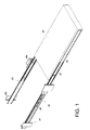
- FIG. 1 shows how a pair of slide rail assemblies 22 in accordance with an embodiment of the present invention are used to mount an object 20 to two pairs of posts of a rack 24.
- the object 20 can be the chassis of a piece of electronic equipment or any other article to be supported in the rack; the present invention imposes no limitations in this respect.
- Each pair of posts include a first post 26a and a second post 26b spaced apart from the first post 26a.
- Each slide rail assembly 22 includes a first rail 28 and a second rail 30 and may, as in this embodiment, further include a third rail 32 configured to be mounted with the object 20.
- the second rail 30 serves to extend the distance by which the third rail 32 can be displaced relative to the first rail 28, and consequently the distance by which the object 20 can be pulled out of the rack 24.
- the slide rail assembly 22 includes a blocking member 34 and an operating member 36 in addition to the first rail 28, the second rail 30, and the third rail 32.
- the first rail 28 has two portions (e.g., a front portion and a rear portion) which can be mounted to the first post 26a and the second post 26b via a first bracket 38 and a second bracket 40 respectively such that the first rail 28 lies between the two posts.
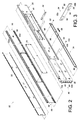
- the first rail 28 includes an upper wall 42a, a lower wall 42b, and a sidewall 44 extending between the upper wall 42a and the lower wall 42b.
- the upper wall 42a, the lower wall 42b, and the sidewall 44 jointly define a longitudinal channel 46.
- the sidewall 44 has an opening 48 in communication with the longitudinal channel 46.
- the blocking member 34 can be attached to the sidewall 44 of the first rail 28, either directly or indirectly, and hence be viewed as a part of the first rail 28.
- the blocking member 34 has a stop wall 50 corresponding to the opening 48 of the first rail 28.
- the blocking member 34 can be an elastic plate and have a first portion 52a, a second portion 52b, a main body portion 54, and an auxiliary portion 56.
- the first portion 52a is configured to be connected to the sidewall 44 of the first rail 28.
- the second portion 52b is distant from the first portion 52a.
- the main body portion 54 and the auxiliary portion 56 are located between the first portion 52a and the second portion 52b.
- the auxiliary portion 56 is raised transversely from the main body portion 54 and extends toward the opening 48 of the first rail 28.
- the auxiliary portion 56 includes a guide section 60 adjacent to the stop wall 50. It is worth mentioning that, while the blocking member 34 is illustrated herein as an elastic plate, the blocking member 34 in another embodiment (not shown) can be biased by an elastic element so as to have elasticity.
- the second rail 30 is movably connected to the first rail 28 and can be displaced relative to the first rail 28 in the longitudinal channel 46.
- the second rail 30 includes an upper wall 64a, a lower wall 64b, and a sidewall 66 extending between the upper wall 64a and the lower wall 64b.
- the upper wall 64a, the lower wall 64b, and the sidewall 66 jointly define a longitudinal channel 68.
- the slide rail assembly 22 further includes a reinforcement structure 70 connected to the sidewall 66 of at least one section of the second rail 30.
- the reinforcement structure 70 is shown as a longitudinal plate by way of example and has a thickness for enhancing the structural strength of the at least one section of the second rail 30 for supporting the third rail 32.
- the slide rail assembly 22 includes a positioning member 72 arranged at the second rail 30.
- the positioning member 72 is movably (e.g., pivotally) connected to the sidewall 66 of the second rail 30 by a connecting element 74 and is adjacent to a rear portion 76 of the second rail 30.
- the positioning member 72 and the reinforcement structure 70 are located on different sides of the second rail 30 but are not necessarily so in practice.
- the sidewall 66 of the second rail 30 further includes a mounting hole 78 and a mounting portion 80 adjacent to the mounting hole 78
- the positioning member 72 includes a main body portion 82 and a portion 84, which can be configured as transversely connected to the main body portion 82.
- the portion 84 of the positioning member 72 can extend through the mounting hole 78.
- a first elastic member 86 is provided between the positioning member 72 and the mounting portion 80.
- the first elastic member 86 can be an elastic clip pressed between the positioning member 72 and the mounting portion 80 but is by no means limited to this configuration.
- the first elastic member 86 applies an elastic force to the positioning member 72 to elastically retain the positioning member 72 at a predetermined position relative to the second rail 30. As shown in FIG.
- the operating member 36 is movably connected to the sidewall 44 of the first rail 28 and is configured for operating the blocking member 34.
- the operating member 36 has a longitudinal main body 88, an operating portion 90, and a contact portion 92, wherein the operating portion 90 and the contact portion 92 are respectively connected to two corresponding ends of the longitudinal main body 88.
- the operating portion 90 is adjacent to the front portion of the first rail 28 in order to be operated by an operator with ease.
- the first bracket 38 includes at least one hole 94, and the operating portion 90 is configured to extend through the at least one hole 94.
- the contact portion 92 can be a projection adjacent to the opening 48 of the sidewall 44 of the first rail 28.
- the slide rail assembly 22 further includes a second elastic member 96 arranged between the first rail 28 and the operating member 36.
- each of the first rail 28 and the operating member 36 has a connecting portion 98
- the second elastic member 96 has two opposite portions respectively connected to the connecting portion 98 of the first rail 28 and the connecting portion 98 of the operating member 36.
- one of the first rail 28 and the operating member 36 may further include at least one slot 100.
- the operating member 36 By passing a portion of a connecting element 102 through the at least one slot 100 and having another portion of the connecting element 102 blocked at one side of the operating member 36, the operating member 36 is connected to the first rail 28 and can be longitudinally displaced relative to the first rail 28 as far as the length of the at least one slot 100 allows.
- the third rail 32 is longitudinally movably connected to the second rail 30 and can be displaced relative to the second rail 30 in the longitudinal channel 68 of the second rail 30.
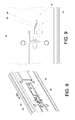
- the slide rail assembly 22 can be mounted to the first post 26a and the second post 26b via the first bracket 38 and the second bracket 40 respectively. More specifically, the second bracket 40 as well as the first bracket 38 may have at least one hole 94, and the at least one hole 94 of each bracket is attached with a mounting member (not shown) to be mounted to one of plural perforations 104 of the first or second post 26a, 26b in order to mount the slide rail assembly 22 to the first post 26a and the second post 26b.
- the operating portion 90 of the operating member 36 can be configured to extend through one of the perforations 104 of the first post 26a but is not limited to this configuration in practice.
- the positioning member 72 is spaced from the blocking member 34.
- the portion 84 of the positioning member 72 can be guided by the guide section 60 of the blocking member 34.
- the portion 84 of the positioning member 72 can be guided by the guide section 60 of the blocking member 34 until blocked by the stop wall 50.
- the guide section 60 includes a rising slope by way of example. While the second rail 30 is being displaced in the direction D1 toward the extended position, the portion 84 of the positioning member 72 is displaced according to the guide section 60, with the positioning member 72 rotated by an angle, and is consequently blocked by the stop wall 50.
- the second rail 30, when the portion 84 of the positioning member 72 is blocked by the stop wall 50, is positioned at the extended position P (see FIG. 5 ) relative to the first rail 28 and cannot be displaced relative to the first rail 28 in a retracting direction (which is the opposite direction of the direction D1).
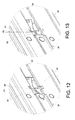
- the operating portion 90 of the operating member 36 when it is desired to release the portion 84 of the positioning member 72 from the stop wall 50 of the blocking member 34, the operating portion 90 of the operating member 36 (see FIG. 6 ) can be operated so that the operating member 36 is displaced from a first position P1 to a second position P2.
- the blocking member 34 is operated by the contact portion 92 of the operating member 36 and shifted in a certain direction (e.g., in a transverse direction as shown in FIG. 13 , but not necessarily so) to release the portion 84 of the positioning member 72 from the stop wall 50 of the blocking member 34.
- the blocking member 34 also has a contact portion (e.g., a projection), by means of which the contact portion 92 of the operating member 36 can operate the blocking member 34, or more particularly can shift the blocking member 34 in the aforesaid direction.
- a contact portion e.g., a projection
- the shifting mechanism of the blocking member 34 is not limited to the foregoing.
- the second rail 30 is allowed to be displaced from the extended position in the retracting direction relative to the first rail 28.
- the operating member 36 is able to automatically return from the position as shown in FIG. 14 to its initial position as shown in FIG. 15 ; that is to say, the operating member 36 is able to automatically move from the second position P2 back to the first position P1.
- the reinforcement structure 70 of the second rail 30 passes the blocking member 34, presses against the blocking member 34 under the guidance of an inclined portion 58 of the blocking member 34, and thus shifts the blocking member 34 in a transverse direction, allowing the second rail 30 to be retracted relative to the first rail 28.
- the second rail 30 is further displaced in the retracting direction D2, with the reinforcement structure 70 displaced along with the second rail 30 to a certain position relative to the blocking member 34.
- the second rail 30 can be displaced further in the retracting direction D2, as shown in FIG. 18, FIG. 18A , and FIG. 19A , until fully retracted, in which state the slide rail assembly 22 has a length L.
- the overall extended length of the slide rail assembly 22 can be shortened by retracting the second rail 30, with a view to meeting the needs of a particular environment.
- the slide rail assembly 22 is used in a certain environment to mount the object 20 to the rack 24.
- a first space S1 exists between the third rail 32 (or the object 20) and an obstacle 106 (e.g., a wall, door, or other obstacle in the environment). If the first space S1 is too small, it will be impossible to perform maintenance work on the object 20 or the slide rail assembly 22. However, the operator can in that case release the portion 84 of the positioning member 72 from the stop wall 50 of the blocking member 34 by operating the operating member 36 (see description associated with FIG.
- FIG. 20A and FIG. 20B show another embodiment of the operating member.
- the contact portion 202 of the operating member 200 is adjacent to the blocking member 204.
- the operating member 200 can be operated and hence displaced from the first position P21 to a second position P22, in order for the contact portion 202 to operate the blocking member 204, or more particularly to shift the blocking member 204 in a certain direction, so that the portion 206 of the positioning member is released from the stop wall 208 of the blocking member 204.
Applications Claiming Priority (1)
| Application Number | Priority Date | Filing Date | Title |
|---|---|---|---|
| TW104111885A TWI601472B (zh) | 2015-04-13 | 2015-04-13 | 滑軌總成 |
Publications (2)
| Publication Number | Publication Date |
|---|---|
| EP3082387A1 true EP3082387A1 (fr) | 2016-10-19 |
| EP3082387B1 EP3082387B1 (fr) | 2020-01-15 |
Family
ID=54705031
Family Applications (1)
| Application Number | Title | Priority Date | Filing Date |
|---|---|---|---|
| EP15196014.3A Active EP3082387B1 (fr) | 2015-04-13 | 2015-11-24 | Ensemble de rail de glissement |
Country Status (4)
| Country | Link |
|---|---|
| US (1) | US9681749B2 (fr) |
| EP (1) | EP3082387B1 (fr) |
| JP (1) | JP6283012B2 (fr) |
| TW (1) | TWI601472B (fr) |
Cited By (1)
| Publication number | Priority date | Publication date | Assignee | Title |
|---|---|---|---|---|
| EP3550944A1 (fr) * | 2018-04-02 | 2019-10-09 | King Slide Works Co., Ltd. | Ensemble rail coulissant et système de rayonnage |
Families Citing this family (23)
| Publication number | Priority date | Publication date | Assignee | Title |
|---|---|---|---|---|
| US10149402B1 (en) * | 2015-09-30 | 2018-12-04 | EMC IP Holding Company LLC | Rack-mountable IT device |
| TWI605776B (zh) * | 2016-05-31 | 2017-11-21 | 川湖科技股份有限公司 | 滑軌總成 |
| US10213017B2 (en) * | 2016-10-05 | 2019-02-26 | King Slide Works Co., Ltd. | Slide rail assembly |
| JP6428826B2 (ja) * | 2017-03-30 | 2018-11-28 | 日本電気株式会社 | スライドレールユニット |
| US10356931B1 (en) * | 2017-05-26 | 2019-07-16 | King Slide Works Co., Ltd. | Rack mounting system |
| TWI658803B (zh) * | 2017-12-28 | 2019-05-11 | 川湖科技股份有限公司 | 滑軌總成及其滑軌套件 |
| US10736422B2 (en) * | 2018-10-04 | 2020-08-11 | King Slide Works Co., Ltd. | Slide rail assembly |
| TWI702019B (zh) | 2019-05-06 | 2020-08-21 | 川湖科技股份有限公司 | 滑軌總成 |
| TWI700056B (zh) | 2019-06-12 | 2020-08-01 | 川湖科技股份有限公司 | 滑軌總成 |
| TWI700057B (zh) | 2019-06-12 | 2020-08-01 | 川湖科技股份有限公司 | 滑軌總成及其操作方法 |
| TWI704856B (zh) * | 2019-07-23 | 2020-09-11 | 啓碁科技股份有限公司 | 櫃體 |
| TWI706751B (zh) * | 2019-08-14 | 2020-10-11 | 川湖科技股份有限公司 | 滑軌總成 |
| CN112412976B (zh) * | 2019-08-22 | 2022-07-29 | 川湖科技股份有限公司 | 滑轨总成 |
| CN112576624B (zh) * | 2019-09-27 | 2022-07-29 | 川湖科技股份有限公司 | 滑轨总成 |
| CN112704342B (zh) * | 2019-10-25 | 2023-05-05 | 川湖科技股份有限公司 | 滑轨总成及其滑轨套件 |
| TWI704889B (zh) | 2019-10-28 | 2020-09-21 | 川湖科技股份有限公司 | 滑軌總成 |
| TWI706752B (zh) * | 2019-11-18 | 2020-10-11 | 川湖科技股份有限公司 | 滑軌總成 |
| TWI706749B (zh) | 2019-11-18 | 2020-10-11 | 川湖科技股份有限公司 | 滑軌總成 |
| TWI737555B (zh) * | 2020-12-22 | 2021-08-21 | 川湖科技股份有限公司 | 滑軌總成及其滑軌套件 |
| TWI750987B (zh) | 2020-12-30 | 2021-12-21 | 川湖科技股份有限公司 | 滑軌總成 |
| TWI738613B (zh) | 2021-02-01 | 2021-09-01 | 川湖科技股份有限公司 | 滑軌總成 |
| CN114847691B (zh) * | 2021-02-04 | 2023-11-24 | 川湖科技股份有限公司 | 滑轨总成 |
| US11864652B1 (en) * | 2022-06-29 | 2024-01-09 | Martas Precision Slide Co., Ltd. | Geometric reinforcing structure for slide rail |
Citations (5)
| Publication number | Priority date | Publication date | Assignee | Title |
|---|---|---|---|---|
| US20020081887A1 (en) * | 2000-12-22 | 2002-06-27 | Judge Ronald J. | Controller for a quick disconnect slide assembly |
| US20080164795A1 (en) * | 2007-01-10 | 2008-07-10 | Hong Fu Jin Precision Industry (Shenzhen) Co., Ltd. | Slide rail assembly |
| US7677679B2 (en) | 2007-06-15 | 2010-03-16 | Hong Fu Jin Precision Industry (Shenzhen) Co., Ltd. | Slide assembly |
| EP2440027A2 (fr) * | 2010-09-13 | 2012-04-11 | Hong Fu Jin Precision Industry (ShenZhen) Co. Ltd. | Ensemble de rail de glissement |
| US20130016461A1 (en) * | 2011-07-13 | 2013-01-17 | Hon Hai Precision Industry Co., Ltd. | Slide assembly |
Family Cites Families (12)
| Publication number | Priority date | Publication date | Assignee | Title |
|---|---|---|---|---|
| US6209979B1 (en) * | 2000-02-22 | 2001-04-03 | General Devices Co., Ltd. | Telescoping slide with quick-mount system |
| TW489618U (en) | 2001-01-05 | 2002-06-01 | King Slide Works Co Ltd | Front-pulling type latch mechanism for rail |
| US6367899B1 (en) | 2001-09-28 | 2002-04-09 | King Slide Works Co., Ltd. | Forward pull type bolt lock structure of a slide |
| US6375290B1 (en) | 2001-09-28 | 2002-04-23 | King Slide Works Co., Ltd. | Lock snap structure of slide rail |
| US6705689B2 (en) | 2002-03-22 | 2004-03-16 | King Slide Works Co., Ltd. | Track device allowing sequential inward movement |
| US6851774B2 (en) | 2003-03-06 | 2005-02-08 | King Slide Works Co., Ltd. | Retaining structure for a track device for drawers |
| TWI261509B (en) | 2005-06-24 | 2006-09-11 | King Slide Works Co Ltd | Positioning device for a tri-sector slide |
| US7571968B2 (en) * | 2006-11-09 | 2009-08-11 | Central Industrial Supply Company | Front release lock with disconnect lock for a drawer slide |
| TWI402046B (zh) * | 2009-04-10 | 2013-07-21 | King Slide Works Co Ltd | 用於滑軌組件之彈性機構 |
| US8240789B2 (en) | 2010-05-12 | 2012-08-14 | King Slide Works Co., Ltd. | Positioning device for slide assembly |
| US8528999B2 (en) | 2011-09-06 | 2013-09-10 | King Slide Works Co., Ltd. | Slide assembly with positioning device |
| TWI448263B (zh) * | 2012-05-30 | 2014-08-11 | King Slide Works Co Ltd | 滑軌總成 |
-
2015
- 2015-04-13 TW TW104111885A patent/TWI601472B/zh active
- 2015-11-11 US US14/937,941 patent/US9681749B2/en active Active
- 2015-11-20 JP JP2015227491A patent/JP6283012B2/ja active Active
- 2015-11-24 EP EP15196014.3A patent/EP3082387B1/fr active Active
Patent Citations (5)
| Publication number | Priority date | Publication date | Assignee | Title |
|---|---|---|---|---|
| US20020081887A1 (en) * | 2000-12-22 | 2002-06-27 | Judge Ronald J. | Controller for a quick disconnect slide assembly |
| US20080164795A1 (en) * | 2007-01-10 | 2008-07-10 | Hong Fu Jin Precision Industry (Shenzhen) Co., Ltd. | Slide rail assembly |
| US7677679B2 (en) | 2007-06-15 | 2010-03-16 | Hong Fu Jin Precision Industry (Shenzhen) Co., Ltd. | Slide assembly |
| EP2440027A2 (fr) * | 2010-09-13 | 2012-04-11 | Hong Fu Jin Precision Industry (ShenZhen) Co. Ltd. | Ensemble de rail de glissement |
| US20130016461A1 (en) * | 2011-07-13 | 2013-01-17 | Hon Hai Precision Industry Co., Ltd. | Slide assembly |
Cited By (1)
| Publication number | Priority date | Publication date | Assignee | Title |
|---|---|---|---|---|
| EP3550944A1 (fr) * | 2018-04-02 | 2019-10-09 | King Slide Works Co., Ltd. | Ensemble rail coulissant et système de rayonnage |
Also Published As
| Publication number | Publication date |
|---|---|
| EP3082387B1 (fr) | 2020-01-15 |
| US9681749B2 (en) | 2017-06-20 |
| JP6283012B2 (ja) | 2018-02-21 |
| JP2016198474A (ja) | 2016-12-01 |
| TW201635952A (zh) | 2016-10-16 |
| TWI601472B (zh) | 2017-10-01 |
| US20160296017A1 (en) | 2016-10-13 |
Similar Documents
| Publication | Publication Date | Title |
|---|---|---|
| EP3082387B1 (fr) | Ensemble de rail de glissement | |
| US9629459B2 (en) | Slide rail assembly | |
| EP3661340B1 (fr) | Dispositif de support | |
| EP3091824A1 (fr) | Dispositif de support | |
| EP3122164B1 (fr) | Ensemble rail coulissant et son dispositif de support | |
| US9681573B2 (en) | Slide rail assembly | |
| EP3136830B1 (fr) | Ensemble rail coulissant et son dispositif de support | |
| EP3275338A1 (fr) | Ensemble de rail de glissement | |
| US9723746B2 (en) | Slide rail assembly | |
| US9125489B2 (en) | Fixing device for a slide assembly | |
| EP3131375B1 (fr) | Ensemble rail coulissant et son dispositif de support | |
| EP3135156A1 (fr) | Glissière télescopique | |
| US20170196354A1 (en) | Bracket device | |
| EP3614816B1 (fr) | Ensemble de couplage et son dispositif de gestion de câbles | |
| US20170079428A1 (en) | Slide rail assembly with interlock device | |
| US20160227666A1 (en) | Slide rail assembly | |
| EP3550944A1 (fr) | Ensemble rail coulissant et système de rayonnage | |
| EP3094166A1 (fr) | Ensemble de rail de glissement | |
| EP3073811A1 (fr) | Ensemble de rail de glissement | |
| EP3030065B1 (fr) | Dispositif de support de bras de gestion de câble et ensemble de montage de celui-ci | |
| EP2979582B1 (fr) | Ensemble de rail de glissement | |
| US9755687B2 (en) | Housing mounting mechanism for portable electronic device | |
| EP3005901B1 (fr) | Ensemble de rail de glissement | |
| EP2813160B1 (fr) | Dispositif de fixation pour assemblage coulissant | |
| US11064807B2 (en) | Slide rail assembly |
Legal Events
| Date | Code | Title | Description |
|---|---|---|---|
| PUAI | Public reference made under article 153(3) epc to a published international application that has entered the european phase |
Free format text: ORIGINAL CODE: 0009012 |
|
| AK | Designated contracting states |
Kind code of ref document: A1 Designated state(s): AL AT BE BG CH CY CZ DE DK EE ES FI FR GB GR HR HU IE IS IT LI LT LU LV MC MK MT NL NO PL PT RO RS SE SI SK SM TR |
|
| AX | Request for extension of the european patent |
Extension state: BA ME |
|
| STAA | Information on the status of an ep patent application or granted ep patent |
Free format text: STATUS: REQUEST FOR EXAMINATION WAS MADE |
|
| 17P | Request for examination filed |
Effective date: 20161229 |
|
| RBV | Designated contracting states (corrected) |
Designated state(s): AL AT BE BG CH CY CZ DE DK EE ES FI FR GB GR HR HU IE IS IT LI LT LU LV MC MK MT NL NO PL PT RO RS SE SI SK SM TR |
|
| STAA | Information on the status of an ep patent application or granted ep patent |
Free format text: STATUS: EXAMINATION IS IN PROGRESS |
|
| 17Q | First examination report despatched |
Effective date: 20180705 |
|
| GRAP | Despatch of communication of intention to grant a patent |
Free format text: ORIGINAL CODE: EPIDOSNIGR1 |
|
| STAA | Information on the status of an ep patent application or granted ep patent |
Free format text: STATUS: GRANT OF PATENT IS INTENDED |
|
| RIC1 | Information provided on ipc code assigned before grant |
Ipc: A47B 88/57 20170101ALI20190718BHEP Ipc: A47B 88/49 20170101ALI20190718BHEP Ipc: H05K 7/14 20060101AFI20190718BHEP |
|
| INTG | Intention to grant announced |
Effective date: 20190812 |
|
| GRAS | Grant fee paid |
Free format text: ORIGINAL CODE: EPIDOSNIGR3 |
|
| GRAA | (expected) grant |
Free format text: ORIGINAL CODE: 0009210 |
|
| STAA | Information on the status of an ep patent application or granted ep patent |
Free format text: STATUS: THE PATENT HAS BEEN GRANTED |
|
| AK | Designated contracting states |
Kind code of ref document: B1 Designated state(s): AL AT BE BG CH CY CZ DE DK EE ES FI FR GB GR HR HU IE IS IT LI LT LU LV MC MK MT NL NO PL PT RO RS SE SI SK SM TR |
|
| REG | Reference to a national code |
Ref country code: CH Ref legal event code: EP Ref country code: GB Ref legal event code: FG4D |
|
| REG | Reference to a national code |
Ref country code: IE Ref legal event code: FG4D |
|
| REG | Reference to a national code |
Ref country code: DE Ref legal event code: R096 Ref document number: 602015045536 Country of ref document: DE |
|
| REG | Reference to a national code |
Ref country code: AT Ref legal event code: REF Ref document number: 1226320 Country of ref document: AT Kind code of ref document: T Effective date: 20200215 |
|
| REG | Reference to a national code |
Ref country code: NL Ref legal event code: MP Effective date: 20200115 |
|
| REG | Reference to a national code |
Ref country code: LT Ref legal event code: MG4D |
|
| PG25 | Lapsed in a contracting state [announced via postgrant information from national office to epo] |
Ref country code: RS Free format text: LAPSE BECAUSE OF FAILURE TO SUBMIT A TRANSLATION OF THE DESCRIPTION OR TO PAY THE FEE WITHIN THE PRESCRIBED TIME-LIMIT Effective date: 20200115 Ref country code: FI Free format text: LAPSE BECAUSE OF FAILURE TO SUBMIT A TRANSLATION OF THE DESCRIPTION OR TO PAY THE FEE WITHIN THE PRESCRIBED TIME-LIMIT Effective date: 20200115 Ref country code: NO Free format text: LAPSE BECAUSE OF FAILURE TO SUBMIT A TRANSLATION OF THE DESCRIPTION OR TO PAY THE FEE WITHIN THE PRESCRIBED TIME-LIMIT Effective date: 20200415 Ref country code: PT Free format text: LAPSE BECAUSE OF FAILURE TO SUBMIT A TRANSLATION OF THE DESCRIPTION OR TO PAY THE FEE WITHIN THE PRESCRIBED TIME-LIMIT Effective date: 20200607 Ref country code: NL Free format text: LAPSE BECAUSE OF FAILURE TO SUBMIT A TRANSLATION OF THE DESCRIPTION OR TO PAY THE FEE WITHIN THE PRESCRIBED TIME-LIMIT Effective date: 20200115 |
|
| PG25 | Lapsed in a contracting state [announced via postgrant information from national office to epo] |
Ref country code: LV Free format text: LAPSE BECAUSE OF FAILURE TO SUBMIT A TRANSLATION OF THE DESCRIPTION OR TO PAY THE FEE WITHIN THE PRESCRIBED TIME-LIMIT Effective date: 20200115 Ref country code: SE Free format text: LAPSE BECAUSE OF FAILURE TO SUBMIT A TRANSLATION OF THE DESCRIPTION OR TO PAY THE FEE WITHIN THE PRESCRIBED TIME-LIMIT Effective date: 20200115 Ref country code: IS Free format text: LAPSE BECAUSE OF FAILURE TO SUBMIT A TRANSLATION OF THE DESCRIPTION OR TO PAY THE FEE WITHIN THE PRESCRIBED TIME-LIMIT Effective date: 20200515 Ref country code: BG Free format text: LAPSE BECAUSE OF FAILURE TO SUBMIT A TRANSLATION OF THE DESCRIPTION OR TO PAY THE FEE WITHIN THE PRESCRIBED TIME-LIMIT Effective date: 20200415 Ref country code: HR Free format text: LAPSE BECAUSE OF FAILURE TO SUBMIT A TRANSLATION OF THE DESCRIPTION OR TO PAY THE FEE WITHIN THE PRESCRIBED TIME-LIMIT Effective date: 20200115 |
|
| REG | Reference to a national code |
Ref country code: DE Ref legal event code: R097 Ref document number: 602015045536 Country of ref document: DE |
|
| PG25 | Lapsed in a contracting state [announced via postgrant information from national office to epo] |
Ref country code: EE Free format text: LAPSE BECAUSE OF FAILURE TO SUBMIT A TRANSLATION OF THE DESCRIPTION OR TO PAY THE FEE WITHIN THE PRESCRIBED TIME-LIMIT Effective date: 20200115 Ref country code: SM Free format text: LAPSE BECAUSE OF FAILURE TO SUBMIT A TRANSLATION OF THE DESCRIPTION OR TO PAY THE FEE WITHIN THE PRESCRIBED TIME-LIMIT Effective date: 20200115 Ref country code: LT Free format text: LAPSE BECAUSE OF FAILURE TO SUBMIT A TRANSLATION OF THE DESCRIPTION OR TO PAY THE FEE WITHIN THE PRESCRIBED TIME-LIMIT Effective date: 20200115 Ref country code: DK Free format text: LAPSE BECAUSE OF FAILURE TO SUBMIT A TRANSLATION OF THE DESCRIPTION OR TO PAY THE FEE WITHIN THE PRESCRIBED TIME-LIMIT Effective date: 20200115 Ref country code: SK Free format text: LAPSE BECAUSE OF FAILURE TO SUBMIT A TRANSLATION OF THE DESCRIPTION OR TO PAY THE FEE WITHIN THE PRESCRIBED TIME-LIMIT Effective date: 20200115 Ref country code: ES Free format text: LAPSE BECAUSE OF FAILURE TO SUBMIT A TRANSLATION OF THE DESCRIPTION OR TO PAY THE FEE WITHIN THE PRESCRIBED TIME-LIMIT Effective date: 20200115 Ref country code: CZ Free format text: LAPSE BECAUSE OF FAILURE TO SUBMIT A TRANSLATION OF THE DESCRIPTION OR TO PAY THE FEE WITHIN THE PRESCRIBED TIME-LIMIT Effective date: 20200115 Ref country code: RO Free format text: LAPSE BECAUSE OF FAILURE TO SUBMIT A TRANSLATION OF THE DESCRIPTION OR TO PAY THE FEE WITHIN THE PRESCRIBED TIME-LIMIT Effective date: 20200115 |
|
| REG | Reference to a national code |
Ref country code: AT Ref legal event code: MK05 Ref document number: 1226320 Country of ref document: AT Kind code of ref document: T Effective date: 20200115 |
|
| PLBE | No opposition filed within time limit |
Free format text: ORIGINAL CODE: 0009261 |
|
| STAA | Information on the status of an ep patent application or granted ep patent |
Free format text: STATUS: NO OPPOSITION FILED WITHIN TIME LIMIT |
|
| 26N | No opposition filed |
Effective date: 20201016 |
|
| PG25 | Lapsed in a contracting state [announced via postgrant information from national office to epo] |
Ref country code: AT Free format text: LAPSE BECAUSE OF FAILURE TO SUBMIT A TRANSLATION OF THE DESCRIPTION OR TO PAY THE FEE WITHIN THE PRESCRIBED TIME-LIMIT Effective date: 20200115 Ref country code: IT Free format text: LAPSE BECAUSE OF FAILURE TO SUBMIT A TRANSLATION OF THE DESCRIPTION OR TO PAY THE FEE WITHIN THE PRESCRIBED TIME-LIMIT Effective date: 20200115 |
|
| PG25 | Lapsed in a contracting state [announced via postgrant information from national office to epo] |
Ref country code: SI Free format text: LAPSE BECAUSE OF FAILURE TO SUBMIT A TRANSLATION OF THE DESCRIPTION OR TO PAY THE FEE WITHIN THE PRESCRIBED TIME-LIMIT Effective date: 20200115 Ref country code: PL Free format text: LAPSE BECAUSE OF FAILURE TO SUBMIT A TRANSLATION OF THE DESCRIPTION OR TO PAY THE FEE WITHIN THE PRESCRIBED TIME-LIMIT Effective date: 20200115 |
|
| PG25 | Lapsed in a contracting state [announced via postgrant information from national office to epo] |
Ref country code: MC Free format text: LAPSE BECAUSE OF FAILURE TO SUBMIT A TRANSLATION OF THE DESCRIPTION OR TO PAY THE FEE WITHIN THE PRESCRIBED TIME-LIMIT Effective date: 20200115 |
|
| REG | Reference to a national code |
Ref country code: CH Ref legal event code: PL |
|
| PG25 | Lapsed in a contracting state [announced via postgrant information from national office to epo] |
Ref country code: LU Free format text: LAPSE BECAUSE OF NON-PAYMENT OF DUE FEES Effective date: 20201124 |
|
| REG | Reference to a national code |
Ref country code: BE Ref legal event code: MM Effective date: 20201130 |
|
| PG25 | Lapsed in a contracting state [announced via postgrant information from national office to epo] |
Ref country code: LI Free format text: LAPSE BECAUSE OF NON-PAYMENT OF DUE FEES Effective date: 20201130 Ref country code: CH Free format text: LAPSE BECAUSE OF NON-PAYMENT OF DUE FEES Effective date: 20201130 |
|
| PG25 | Lapsed in a contracting state [announced via postgrant information from national office to epo] |
Ref country code: FR Free format text: LAPSE BECAUSE OF NON-PAYMENT OF DUE FEES Effective date: 20201130 |
|
| PG25 | Lapsed in a contracting state [announced via postgrant information from national office to epo] |
Ref country code: TR Free format text: LAPSE BECAUSE OF FAILURE TO SUBMIT A TRANSLATION OF THE DESCRIPTION OR TO PAY THE FEE WITHIN THE PRESCRIBED TIME-LIMIT Effective date: 20200115 Ref country code: MT Free format text: LAPSE BECAUSE OF FAILURE TO SUBMIT A TRANSLATION OF THE DESCRIPTION OR TO PAY THE FEE WITHIN THE PRESCRIBED TIME-LIMIT Effective date: 20200115 Ref country code: CY Free format text: LAPSE BECAUSE OF FAILURE TO SUBMIT A TRANSLATION OF THE DESCRIPTION OR TO PAY THE FEE WITHIN THE PRESCRIBED TIME-LIMIT Effective date: 20200115 |
|
| PG25 | Lapsed in a contracting state [announced via postgrant information from national office to epo] |
Ref country code: MK Free format text: LAPSE BECAUSE OF FAILURE TO SUBMIT A TRANSLATION OF THE DESCRIPTION OR TO PAY THE FEE WITHIN THE PRESCRIBED TIME-LIMIT Effective date: 20200115 Ref country code: AL Free format text: LAPSE BECAUSE OF FAILURE TO SUBMIT A TRANSLATION OF THE DESCRIPTION OR TO PAY THE FEE WITHIN THE PRESCRIBED TIME-LIMIT Effective date: 20200115 |
|
| PG25 | Lapsed in a contracting state [announced via postgrant information from national office to epo] |
Ref country code: GR Free format text: LAPSE BECAUSE OF FAILURE TO SUBMIT A TRANSLATION OF THE DESCRIPTION OR TO PAY THE FEE WITHIN THE PRESCRIBED TIME-LIMIT Effective date: 20200115 Ref country code: BE Free format text: LAPSE BECAUSE OF NON-PAYMENT OF DUE FEES Effective date: 20201130 |
|
| PGFP | Annual fee paid to national office [announced via postgrant information from national office to epo] |
Ref country code: GB Payment date: 20231108 Year of fee payment: 9 |
|
| PGFP | Annual fee paid to national office [announced via postgrant information from national office to epo] |
Ref country code: IE Payment date: 20231108 Year of fee payment: 9 Ref country code: DE Payment date: 20231109 Year of fee payment: 9 |