EP3030065B1 - Dispositif de support de bras de gestion de câble et ensemble de montage de celui-ci - Google Patents
Dispositif de support de bras de gestion de câble et ensemble de montage de celui-ci Download PDFInfo
- Publication number
- EP3030065B1 EP3030065B1 EP14196223.3A EP14196223A EP3030065B1 EP 3030065 B1 EP3030065 B1 EP 3030065B1 EP 14196223 A EP14196223 A EP 14196223A EP 3030065 B1 EP3030065 B1 EP 3030065B1
- Authority
- EP
- European Patent Office
- Prior art keywords
- supporting
- arm
- mounting
- mounting member
- elastic
- Prior art date
- Legal status (The legal status is an assumption and is not a legal conclusion. Google has not performed a legal analysis and makes no representation as to the accuracy of the status listed.)
- Active
Links
- 230000000903 blocking effect Effects 0.000 claims description 15
- 230000000712 assembly Effects 0.000 description 8
- 238000000429 assembly Methods 0.000 description 8
- 238000006073 displacement reaction Methods 0.000 description 2
- 238000000034 method Methods 0.000 description 1
Images


Classifications
-
- H—ELECTRICITY
- H05—ELECTRIC TECHNIQUES NOT OTHERWISE PROVIDED FOR
- H05K—PRINTED CIRCUITS; CASINGS OR CONSTRUCTIONAL DETAILS OF ELECTRIC APPARATUS; MANUFACTURE OF ASSEMBLAGES OF ELECTRICAL COMPONENTS
- H05K7/00—Constructional details common to different types of electric apparatus
- H05K7/14—Mounting supporting structure in casing or on frame or rack
- H05K7/1485—Servers; Data center rooms, e.g. 19-inch computer racks
- H05K7/1488—Cabinets therefor, e.g. chassis or racks or mechanical interfaces between blades and support structures
- H05K7/1491—Cabinets therefor, e.g. chassis or racks or mechanical interfaces between blades and support structures having cable management arrangements
Definitions
- the present invention relates to a cable management arm (CMA) and, more particularly, to a cable management arm supporting device whose supporting members can be rapidly assembled to applicable slide rail assemblies and be easily and rapidly detached from the slide rail assemblies when desired.
- CMA cable management arm
- a cable management arm (CMA) (24) includes two pivotally connected support sections (26, 28) which are respectively connected to a chassis member (22) and to a cabinet member (18) of a drawer slide.
- a telescoping support crossbar (42) includes a first member (46) and a second member (48) slidably extensible from the first member (46).
- 3-5 of the patent also show that the telescoping support crossbar (42) has two ends (50, 52) which are respectively mounted to an end of an intermediate member (20) of a drawer slide and to the cabinet member (18) of another drawer slide via a pivot fastener (60).
- US2014183306 describes a cable mounting arm supporting device having a mounting assembly with a mounting member which can be rotated into two opposite positions. The mounting member is held in place in each of the two positions by a projection which is engaged in a positioning hole.
- the present invention relates to a cable management arm supporting device whose supporting members can be rapidly assembled to and easily and rapidly detached from applicable slide rail assemblies.
- a cable management arm supporting device is provided to be mounted to a first slide rail assembly and a second slide rail assembly.
- the first slide rail assembly includes a first rail, a second rail, and a third rail movably connected between the first rail and the second rail.
- the cable management arm supporting device includes a first arm, a first mounting member, a second arm, a second mounting member, a plurality of cable supporting features, a supporting base, a first supporting member, a second supporting member, and a third mounting member.
- the first arm has a first end and a second end.
- the first mounting member is connected to the first arm at a position adjacent to the first end of the first arm.
- the first mounting member is mounted to the first rail of the first slide rail assembly.
- the second arm is movably connected to the first arm at a position adjacent to the second end of the first arm.
- the second mounting member is connected with the second arm and is mounted to the second rail of the first slide rail assembly.
- the cable supporting features are connected with at least one of the first arm and the second arm.
- the supporting base has a first supporting portion and a second supporting portion generally perpendicularly connected with the first supporting portion.
- the first supporting member is movably connected with the first supporting portion of the supporting base.
- the second supporting member is telescopically connected with the first supporting member and is mounted to the third rail of the first slide rail assembly.
- the third mounting member is pivotally connected with the second supporting portion of the supporting base and is releasably connected with the second slide rail assembly.
- the first slide rail assembly further includes a first connector connected with the first rail, and the first mounting member is releasably mounted to the first connector.
- the first slide rail assembly further includes a second connector connected with the second rail, and the second mounting member is releasably mounted to the second connector.
- the second slide rail assembly further includes a connector
- the third mounting member further includes a mounting wall and an operation arm connected with the mounting wall.
- the mounting wall includes at least one fixing portion and a first opening.
- the operation arm includes a connecting portion connected with the at least one fixing portion and further includes a first elastic portion.
- the first elastic portion is connected with one side of the connecting portion, corresponds to the first opening, and includes at least one engaging portion for blocking the connector.
- the mounting wall of the third mounting member further includes a second opening
- the operation arm further includes a second elastic portion connected with another side of the connecting portion and corresponding to the second opening and also includes an engaging section connected with the second elastic portion
- the second supporting portion of the supporting base further includes a first positioning portion and a second positioning portion.
- the engaging section can be selectively engaged with either of the first positioning portion and the second positioning portion.
- the cable management arm supporting device further includes an elastic element connected between the third mounting member and the second supporting portion of the supporting base, and the second supporting portion of the supporting base further includes a first stop portion and a second stop portion.
- the third mounting member When pivoted to a first direction, the third mounting member is pressed against the first stop portion due to the elastic element; when pivoted to a second direction opposite the first direction, the third mounting member is pressed against the second stop portion due to the elastic element.
- the first slide rail assembly further includes an auxiliary element connected with the third rail of the first slide rail assembly and a positioning element connected with the second supporting member.
- the auxiliary element includes a mounting opening and an elastic arm.
- the elastic arm has a blocking edge for forming a blockage at the mounting opening.
- the positioning element is mounted in the mounting opening and can be blocked by the blocking edge of the elastic arm.
- the cable management arm supporting device further includes a hinge member, and the first arm and the second arm are pivotally connected by the hinge member.
- the first mounting member is pivotally connected with the first end of the first arm.
- the second mounting member is pivotally connected with the second arm.
- the first supporting member is pivotally connected with the first supporting portion of the supporting base.
- a mounting assembly applicable to a supporting member includes a supporting base and a mounting member.
- the supporting base has a first supporting portion and a second supporting portion generally perpendicularly connected with the first supporting portion.
- the supporting member is movably connected with the first supporting portion.
- the mounting member is pivotally connected with the second supporting portion of the supporting base.
- the mounting member further includes a mounting wall and an operation arm connected with the mounting wall.
- the mounting wall includes at least one fixing portion and a first opening.
- the operation arm includes a connecting portion connected with the at least one fixing portion and further includes a first elastic portion.
- the first elastic portion is connected with one side of the connecting portion, corresponds to the first opening, and includes at least one engaging portion for blocking an object.
- the mounting wall of the mounting member further includes a second opening
- the operation arm further includes a second elastic portion connected with another side of the connecting portion and corresponding to the second opening and also includes an engaging section connected with the second elastic portion
- the second supporting portion of the supporting base further includes a first positioning portion and a second positioning portion.
- the engaging section can be selectively engaged with either of the first positioning portion and the second positioning portion.
- the mounting assembly further includes an elastic element connected between the mounting member and the second supporting portion of the supporting base, and the second supporting portion of the supporting base further includes a first stop portion and a second stop portion.
- the mounting member is pressed against the first stop portion due to the elastic element when pivoted to a first direction and is pressed against the second stop portion due to the elastic element when pivoted to a second direction opposite the first direction.
- One advantageous feature of implementing the present invention is that the supporting members can be rapidly assembled to applicable slide rail assemblies and be easily and rapidly detached from the slide rail assemblies when desired.
- the cable management arm supporting device 20 in an embodiment of the present invention is mounted to a first slide rail assembly 22 and a second slide rail assembly 24.
- Each of the slide rail assemblies 22 and 24 is mounted to a corresponding pair of posts 26.
- Each of the slide rail assemblies 22 and 24 includes a first rail 28, a second rail 30, and a third rail 32 movably connected between the first rail 28 and the second rail 30 so as to increase the distance by which the second rail 30 can be longitudinally displaced relative to the first rail 28.
- the chassis 34 of a server can have its two opposite lateral sides mounted to the second rail 30 of the first slide rail assembly 22 and the second rail of the second slide rail assembly 24 respectively in order for the two slide rail assemblies 22 and 24 to support the chassis 34. (The second rail and the third rail of the second slide rail assembly 24 are not shown in the drawings due to limitations of the viewing angle.)
- the cable management arm supporting device 20 includes a first arm 36, a first mounting member 38, a second arm 40, a second mounting member 42, a plurality of cable supporting features 44, a supporting base 46, a first supporting member 48, a second supporting member 50, and a third mounting member 52.
- the first arm 36 has a first end 54a and a second end 54b.
- the first mounting member 38 is connected to the first arm 36 at a position adjacent to the first end 54a.
- the first mounting member 38 is pivotally connected to the first arm 36 at a position adjacent to the first end 54a.
- the first mounting member 38 is mounted to the first rail 28 of the first slide rail assembly 22.
- the first slide rail assembly 22 includes a first connector 56 connected with the first rail 28 of the first slide rail assembly 22 (e.g., the first connector 56 being connected to the first rail 28 at a position adjacent to an end portion thereof), and the first mounting member 38 is mounted to the first connector 56.
- the first mounting member 38 is releasably mounted to the first connector 56.
- the second arm 40 is movably connected to the first arm 36 at a position adjacent to the second end 54b.
- the second arm 40 is pivotally connected with the first arm 36 via a hinge member 58 (or a hinge structure) in order to be extended (see FIG. 11 ) or retracted relative to the first arm 36.
- the second mounting member 42 is connected with the second arm 40.
- the second mounting member 42 is pivotally connected to the second arm 40 at a position adjacent to an end portion thereof.
- the second mounting member 42 is mounted to the second rail 30 of the first slide rail assembly 22.
- the first slide rail assembly 22 includes a second connector 60 connected with the second rail 30 of the first slide rail assembly 22 (e.g., the second connector 60 being connected to the second rail 30 at a position adjacent to an end portion thereof), and the second mounting member 42 is mounted to the second connector 60.
- the second mounting member 42 is releasably mounted to the second connector 60.
- the cable supporting features 44 are connected with one of the first arm 36 and the second arm 40. In a preferred embodiment, the cable supporting features 44 are connected with both the first arm 36 and the second arm 40. The cable supporting features 44 serve to hold the cables (not shown) of a server.
- the supporting base 46 has a first supporting portion 62 and a second supporting portion 64 generally perpendicularly connected with the first supporting portion 62.
- the first supporting member 48 is movably connected with the first supporting portion 62 of the supporting base 46.
- the second supporting member 50 is telescopically connected with the first supporting member 48.
- the first supporting member 48 and the second supporting member 50 are below one of the first arm 36 and the second arm 40 in order to serve supporting purposes, preventing the first arm 36 and the second arm 40 from falling because of the weight of the cables they carry.
- the second supporting member 50 is mounted to the third rail 32 of the first slide rail assembly 22.
- the first slide rail assembly 22 further includes an auxiliary element 66 connected with the third rail 32 of the first slide rail assembly 22 (e.g., at a position adjacent to an end portion of the third rail 32) and also includes a positioning element 68 connected with the second supporting member 50.
- the auxiliary element 66 includes a mounting opening 70 and an elastic arm 72.
- the elastic arm 72 has one end fixed at an appropriate position and has a blocking edge 74 for forming a blockage at the mounting opening 70.
- the positioning element 68 can be mounted in the mounting opening 70 and be blocked by the blocking edge 74 of the elastic arm 72.
- the blocking edge 74 of the elastic arm 72 can block the positioning element 68 such that the positioning element 68 is mounted in the mounting opening 70 of the auxiliary element 66 (see FIG. 4A ).
- either of the positioning element 68 and the elastic arm 72 has a guiding feature (e.g., an inclined surface), such that the elastic arm 72 of the auxiliary element 66 can be directly pushed up by the positioning element 68 upon connection between the second supporting member 50 and the auxiliary element 66 and then return to its original position to keep the positioning element 68 in place. In that case, manual operation of the elastic arm 72 will be unnecessary.
- the free end of the elastic arm 72 of the auxiliary element 66 can be lifted up to rid the mounting opening 70 of the blockage of the blocking edge 74 of the elastic arm 72 (see FIG. 4B ).
- the positioning element 68 can now be removed from the mounting opening 70 of the auxiliary element 66 (see FIG. 4C ), allowing the second supporting member 50 to be rapidly detached from the third rail 32 of the first slide rail assembly 22.
- the second supporting member 50 is configured to be mounted to the third rail 32 of the first slide rail assembly 22 in a releasable manner.
- the first supporting member 48 is pivotally connected with the first supporting portion 62 of the supporting base 46 via a pivotal connector 49 so as to pivot with respect to the first supporting portion 62 of the supporting base 46.
- the third mounting member 52 is pivotally connected with the second supporting portion 64 of the supporting base 46 via a pivotal connector 53 so as to pivot with respect to the second supporting portion 64 of the supporting base 46.
- the third mounting member 52 is connected with the second slide rail assembly 24 in a releasable manner, as detailed further below.
- the supporting base 46 and the third mounting member 52 can be viewed as a mounting assembly applicable to a supporting member (e.g., the first supporting member 48).
- the mounting assembly enables the supporting member to pivot to different directions via the third mounting member 52 so that the supporting member can be mounted to different objects.
- the supporting member can be mounted to the second slide rail assembly 24 via the third mounting member 52, or the supporting member can be mounted to the first slide rail assembly 22 via the third mounting member 52 (see FIG. 12 ).
- the second slide rail assembly 24 further includes a connector 76 connected with the first rail 28 of the second slide rail assembly 24, and the third mounting member 52 further includes a mounting wall 78 and an operation arm 80 corresponding to and connected with the mounting wall 78.
- the mounting wall 78 includes at least one fixing portion 82 and a first opening 84.
- the operation arm 80 includes a connecting portion 86 corresponding to and fixedly connected with the at least one fixing portion 82.
- the operation arm 80 also includes a first elastic portion 88 connected with one side of the connecting portion 86 and corresponding to the first opening 84.
- the first elastic portion 88 includes at least one engaging portion 90 for blocking an object.
- the at least one engaging portion 90 corresponds to and blocks a portion of the connector 76 to keep the third mounting member 52 and the connector 76 in a mounted state.
- An operator can operate (e.g., press) the first elastic portion 88 through the first opening 84 to displace the at least one engaging portion 90 with respect to the portion of the connector 76, thus releasing the third mounting member 52 and the connector 76 from the mounted state, allowing the third mounting member 52 to be detached from the connector 76.
- the mounting wall 78 of the third mounting member 52 further includes a second opening 92 and a through hole 93
- the operation arm 80 further includes a second elastic portion 94 connected with another side of the connecting portion 86 (for example, but without limitation, the second elastic portion 94 and the first elastic portion 88 are located on two opposite sides of the connecting portion 86 respectively and use the connecting portion 86 as a common fulcrum) and corresponding to the second opening 92.
- an engaging section 96 is connected with the second elastic portion 94.
- the engaging section 96 corresponds to and can pass through the through hole 93 of the mounting wall 78.
- the second supporting portion 64 of the supporting base 46 further includes a first positioning portion 97a and a second positioning portion 97b. The engaging section 96 can engage with the first positioning portion 97a or the second positioning portion 97b after passing through the through hole 93 of the mounting wall 78.
- the third mounting member 52 which is pivotally connected with the second supporting portion 64 of the supporting base 46, can be pivoted to a first direction D1 or a second direction D2.
- the first direction D1 and the second direction D2 are opposite directions.
- the third mounting member 52 therefore, can be mounted to the connector 76 of the second slide rail assembly 24 when pivoted to the first direction D1 and can be mounted to a connector of the first slide rail assembly 22 when pivoted to the second direction D2 (as explained further below with reference to FIGS. 9-12 ).
- the engaging section 96 sequentially passes through the through hole 93 of the mounting wall 78 and the first positioning portion 97a of the supporting base 46 and becomes engaged with the first positioning portion 97a to limit and fix the third mounting member 52 in position.
- the stability of the third mounting member 52 is increased, which is advantageous to the mounting process.
- the operator can apply a force F to (i.e., press) the second elastic portion 94 of the operation arm 80 through the second opening 92 to disengage the engaging section 96 from the through hole 93 and the first positioning portion 97a of the supporting base 46.
- the third mounting member 52 can be pivoted from the first direction D1 to the second direction D2, allowing the engaging section 96 to engage with the second positioning portion 97b of the supporting base 46 and thereby limit and fix the third mounting member 52 in position. Consequently, the stability of the third mounting member 52 is increased, which facilitates mounting.
- the engaging section 96 can selectively engage with either of the first positioning portion 97a and the second positioning portion 97b.
- the chassis 34 is also displaced in the direction D.
- the second mounting member 42 of the cable management arm supporting device 20 is displaced relative to the first mounting member 38 in the direction D, and the second arm 40 is extended relative to the first arm 36. Since the third rail 32 (see FIG. 10 ), when the second rail 30 of the first slide rail assembly 22 and the second rail 30 of the second slide rail assembly 24 are longitudinally displaced a distance L1 in a direction D from the retracted position toward an extended position relative to their respective first rails 28, the chassis 34 is also displaced in the direction D. Meanwhile, the second mounting member 42 of the cable management arm supporting device 20 is displaced relative to the first mounting member 38 in the direction D, and the second arm 40 is extended relative to the first arm 36. Since the third rail 32 (see FIG.
- first slide rail assembly 22 is also driven to displace longitudinally in the direction D by the second rail 30 of the first slide rail assembly 22, the second supporting member 50, which is connected with the third rail 32 of the first slide rail assembly 22 via the positioning element 68, is displaced relative to the first supporting member 48 in response to extension of the second arm 40 relative to the first arm 36.
- the second supporting member 50 which is connected with the third rail 32 of the first slide rail assembly 22 via the positioning element 68, is further displaced relative to the first supporting member 48 in response to further extension of the second arm 40 relative to the first arm 36.
- the second arm 40 is extended (or folded) relative to the first arm 36 in response to displacement of the second rail 30 of the first slide rail assembly 22, and that the second supporting member 50 is displaced relative to the first supporting member 48 in response to displacement of the third rail 32 of the first slide rail assembly 22. Therefore, in the course in which the chassis 34 is pulled out or pushed back in place, the first arm 36 and the second arm 40 jointly provide cable management (e.g., to keep the cables behind the server chassis 34 in neat arrangement) while the first supporting member 48 and the second supporting member 50 cooperate in providing support (e.g., to support the first arm 36).
- cable management e.g., to keep the cables behind the server chassis 34 in neat arrangement
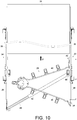
- FIG. 12 shows how the cable management arm supporting device 20 in another embodiment of the present invention is applied to and works with the first slide rail assembly 22 and the second slide rail assembly 24.
- the third mounting member 52 When the third mounting member 52 is pivoted to the second direction D2 (see FIG. 7 ), it can be mounted in a different way from that illustrated in the foregoing embodiment (as shown in FIGS. 9-11 ), or more particularly be mounted to the first connector 56 on the first rail 28 of the first slide rail assembly 22.
- the first mounting member 38 and the second mounting member 42 which are respectively pivotally connected with the first arm 36 and the second arm 40, can also be pivoted to the second direction D2 in order to be mounted to the connector 76 and another connector 76 of the second slide rail assembly 24 respectively.
- the connecters 76 are connected with the first rail 28 and the second rail 30 of the second slide rail assembly 24, respectively. In use, therefore, the arrangement of the cable management arm supporting device 20 with respect to the first slide rail assembly 22 and the second slide rail assembly 24 can be inverted to suit practical needs.
- FIG. 13 shows how the third mounting member 300 of the cable management arm supporting device in the second embodiment of the present invention is arranged in relation to the supporting base 302.
- the third mounting member 300 is pivotally connected with the second supporting portion 304 of the supporting base 302.
- the second embodiment is different from the first embodiment (see FIG. 7 ) in that the cable management arm supporting device further includes an elastic element 306 connected between the third mounting member 300 and the second supporting portion 304 of the supporting base 302, and that the second supporting portion 304 of the supporting base 302 further includes a first stop portion 308 and a second stop portion 310.
Claims (17)
- Ensemble de montage raccordé de manière mobile à un premier élément de support (48) d'un dispositif de support de bras de gestion de câbles (20), l'ensemble de montage caractérisé par le fait qu'il comprend :une base de support (46, 302) présentant une première partie de support (62) et une seconde partie de support (64, 304) raccordée perpendiculairement à la première partie de support (62), le premier élément de support (48) étant raccordé de manière mobile à la première partie de support (62) ; etun troisième élément de montage (52, 300) raccordé de manière pivotante à la seconde partie de support (64, 304) de la base de support (46, 302), pour pivoter dans une première direction (D1) ou une seconde direction (D2) les première et seconde directions (D1, D2) étant des directions opposées,la seconde partie de support (64, 304) comprend une première partie de positionnement (97a) et une seconde partie de positionnement (97b) ou une première partie d'arrêt (308) et une seconde partie d'arrêt (310),le troisième élément de montage (52, 300) vient en prise avec la première partie de positionnement (97a) ou la première partie d'arrêt (308) lorsque pivoté dans la première direction (D1) et vient en prise avec la seconde partie de positionnement (97b) ou la seconde partie d'arrêt (310) lorsque pivoté dans la seconde direction (D2) et est par conséquent limité en position, lorsque pivoté vers les première et seconde directions (D1, D2),caractérisé en ce que,le troisième élément de montage (52, 300) comprend une seconde partie élastique (94) ou un élément élastique (306),le troisième élément de montage (52) vient en prise avec les première et seconde parties de positionnement (97a, 97b) avec une section de mise en prise (96) qui fait partie de la seconde partie élastique (94) ou le troisième élément de montage (300) est pressé contre les première et seconde partie d'arrêts (308) par l'élément élastique (306).
- Ensemble de montage selon la revendication 1, caractérisé par le fait que la seconde partie élastique (94) fait partie d'un bras de commande (80) du troisième élément de montage (52).
- Ensemble de montage selon la revendication 1, caractérisé par le fait que l'élément élastique (306) est raccordé entre le troisième élément de montage (300) et la seconde partie de support (304) de la base de support (302).
- Ensemble de montage selon la revendication 1, caractérisé par le fait que le troisième élément de montage (52, 300) comprend en outre une paroi de montage (78) et un bras de commande (80) raccordé à la paroi de montage (78), la paroi de montage (78) comprend au moins une partie de fixation (82) et une première ouverture (84), le bras de commande (80) comprend une partie de raccordement (86) raccordée à la ou aux parties de fixation (82) et comprend une première partie élastique (88) raccordée à un côté de la partie de raccordement (86) et correspondant à la première ouverture (84), et la première partie élastique (88) comprend au moins une partie de mise en prise (90) pour bloquer un objet (76).
- Ensemble de montage selon la revendication 4, caractérisé par le fait que la paroi de montage (78) du troisième élément de montage (52) comprend une seconde ouverture (92), le bras de commande (80) comprend la seconde partie élastique (94) raccordée à un autre côté de la partie de raccordement (86) et correspondant à la seconde ouverture (92) et comprend également la section de mise en prise (96) raccordée à la seconde partie élastique (94), la seconde partie de support (64) de la base de support (46) comprend la première partie de positionnement (97a) et la seconde partie de positionnement (97b), et la section de mise en prise (96) peut être mise en prise de manière sélective avec soit la première partie de positionnement (97a) soit la seconde partie de positionnement (97b).
- Ensemble de montage selon la revendication 1, caractérisé par le fait que l'élément élastique (306) est raccordé entre le troisième élément de montage (300) et la seconde partie de support (304) de la base de support (302), la seconde partie de support (304) de la base de support (302) comprenant en outre la première partie d'arrêt (308) et la seconde partie d'arrêt (310), le troisième élément de montage (300) est pressé contre la première partie d'arrêt (308) du fait de l'élément élastique (306) lorsque pivoté dans la première direction (D1) et est pressé contre la seconde partie d'arrêt (310) du fait de l'élément élastique (306) lorsque pivoté dans la seconde direction (D2) à l'opposé de la première direction (D1).
- Dispositif de support de bras de gestion de câbles (20), à monter sur un premier ensemble de rails coulissant (22) et un second ensemble de rails coulissant (24), caractérisé par le fait que le premier ensemble de rails coulissant (22) comprend un premier rail (28), un deuxième rail (30), et un troisième rail (32) raccordé de manière mobile entre le premier rail (28) et le deuxième rail (30), le dispositif de support de bras de gestion de câbles (20) caractérisé par le fait qu'il comprend :un premier bras (36) présentant une première extrémité (54a) et une seconde extrémité (54b) ;un premier élément de montage (38) raccordé au premier bras (36) sur une position adjacente à la première extrémité (54a), le premier élément de montage (38) étant monté sur le premier rail (28) du premier ensemble de rails coulissant (22) ;un second bras (40) raccordé de manière mobile au premier bras (36) sur une position adjacente à la seconde extrémité (54b) ;un deuxième élément de montage (42) raccordé au second bras (40), le deuxième élément de montage (42) étant monté sur le deuxième rail (30) du premier ensemble de rails coulissant (22) ;une pluralité de fonctionnalités de support (44) raccordées à au moins l'un des premier bras (36) ou second bras (40) ; etl'ensemble de montage selon la revendication 1, caractérisé par le fait que l'ensemble de montage comprend en outre un second élément de support (50), le second élément de support (50) est raccordé de manière télescopique au premier élément de support (48) et monté sur le troisième rail (32) du premier ensemble de rails coulissant (22), et le troisième élément de montage (52, 300) est raccordé de manière amovible au second ensemble de rails coulissant (24).
- Dispositif de support de bras de gestion de câbles (20) selon la revendication 7, caractérisé par le fait que le premier ensemble de rails coulissant (22) comprend en outre un premier connecteur (56) raccordé au premier rail (28), et le premier élément de montage (38) est monté de manière amovible sur le premier connecteur (56).
- Dispositif de support de bras de gestion de câbles (20) selon la revendication 7, caractérisé par le fait que le premier ensemble de rails coulissant (22) comprend en outre un second connecteur (60) raccordé au deuxième rail (30), et le deuxième élément de montage (42) est monté de manière amovible sur le second connecteur (60).
- Dispositif de support de bras de gestion de câbles (20) selon la revendication 7, caractérisé par le fait que le second ensemble de rails coulissant (24) comprend en outre un connecteur (76), le troisième élément de montage (52, 300) comprend en outre une paroi de montage (78) et un bras de commande (80) raccordé à la paroi de montage (78), la paroi de montage (78) comprend au moins une partie de fixation (82) et une première ouverture (84), le bras de commande (80) comprend une partie de raccordement (86) raccordée à la ou aux parties de fixation (82) et comprend une première partie élastique (88) raccordée à un côté de la partie de raccordement (86) et correspondant à la première ouverture (84), et la première partie élastique (88) comprend au moins une partie de mise en prise (90) pour bloquer le connecteur (76).
- Dispositif de support de bras de gestion de câbles (20) selon la revendication 10, caractérisé par le fait que la paroi de montage (78) du troisième élément de montage (52, 300) comprend une seconde ouverture (92), le bras de commande (80) comprend la seconde partie élastique (94) raccordée à un autre côté de la partie de raccordement (86) et correspondant à la seconde ouverture (92) et comprend également la section de mise en prise (96) raccordée à la seconde partie élastique (94), la seconde partie de support (64) de la base de support (46) comprend la première partie de positionnement (97a) et la seconde partie de positionnement (97b), et la section de mise en prise (96) peut être mise en prise de manière sélective avec soit la première partie de positionnement (97a) soit la seconde partie de positionnement (97b).
- Dispositif de support de bras de gestion de câbles (20) selon la revendication 7, caractérisé par le fait que l'élément élastique (306) est raccordé entre le troisième élément de montage (300) et la seconde partie de support (304) de la base de support (302), la seconde partie de support (304) de la base de support (302) comprenant en outre la première partie d'arrêt (308) et la seconde partie d'arrêt (310), le troisième élément de montage (52, 300) est pressé contre la première partie d'arrêt (308) du fait de l'élément élastique (306) lorsque pivoté dans la première direction (D1) et est pressé contre la seconde partie d'arrêt (310) du fait de l'élément élastique (306) lorsque pivoté dans la seconde direction (D2) à l'opposé de la première direction (D1).
- Dispositif de support de bras de gestion de câbles (20) selon la revendication 7, caractérisé par le fait qu'il comprend en outre un élément auxiliaire (66) raccordé au troisième rail (32) du premier ensemble de rails coulissant (22) et un élément de positionnement (68) raccordé au second élément de support (50), l'élément auxiliaire (66) comprend une ouverture de montage (70) et un bras élastique (72), le bras élastique (72) présente un rebord de blocage (74) pour former un blocage à l'ouverture de montage (70), et l'élément de positionnement (68) est monté dans l'ouverture de montage (70) et peut être bloqué par le rebord de blocage (74) du bras élastique (72).
- Dispositif de support de bras de gestion de câbles (20) selon la revendication 7, caractérisé par le fait qu'il comprend en outre un élément d'articulation (58) par lequel le premier bras (36) et le second bras (40) sont raccordés de manière pivotante.
- Dispositif de support de bras de gestion de câbles (20) selon la revendication 7, caractérisé par le fait que le premier élément de montage (38) est raccordé de manière pivotante avec la première extrémité (54a) du premier bras (36).
- Dispositif de support de bras de gestion de câbles (20) selon la revendication 7, caractérisé par le fait que le deuxième élément de montage (42) est raccordé de manière pivotante avec le second bras (40).
- Dispositif de support de bras de gestion de câbles (20) selon la revendication 7, caractérisé par le fait que le premier élément de support (48) est raccordé de manière pivotante avec la première partie de support (62) de la base de support (46, 302).
Priority Applications (1)
| Application Number | Priority Date | Filing Date | Title |
|---|---|---|---|
| EP14196223.3A EP3030065B1 (fr) | 2014-12-04 | 2014-12-04 | Dispositif de support de bras de gestion de câble et ensemble de montage de celui-ci |
Applications Claiming Priority (1)
| Application Number | Priority Date | Filing Date | Title |
|---|---|---|---|
| EP14196223.3A EP3030065B1 (fr) | 2014-12-04 | 2014-12-04 | Dispositif de support de bras de gestion de câble et ensemble de montage de celui-ci |
Publications (2)
| Publication Number | Publication Date |
|---|---|
| EP3030065A1 EP3030065A1 (fr) | 2016-06-08 |
| EP3030065B1 true EP3030065B1 (fr) | 2018-03-14 |
Family
ID=52002842
Family Applications (1)
| Application Number | Title | Priority Date | Filing Date |
|---|---|---|---|
| EP14196223.3A Active EP3030065B1 (fr) | 2014-12-04 | 2014-12-04 | Dispositif de support de bras de gestion de câble et ensemble de montage de celui-ci |
Country Status (1)
| Country | Link |
|---|---|
| EP (1) | EP3030065B1 (fr) |
Cited By (1)
| Publication number | Priority date | Publication date | Assignee | Title |
|---|---|---|---|---|
| TWI703915B (zh) * | 2019-11-05 | 2020-09-01 | 川湖科技股份有限公司 | 連接機構及其理線裝置 |
Families Citing this family (3)
| Publication number | Priority date | Publication date | Assignee | Title |
|---|---|---|---|---|
| TWI684396B (zh) * | 2019-02-25 | 2020-02-01 | 川湖科技股份有限公司 | 滑軌機構及其支撐總成 |
| TWI725461B (zh) * | 2019-06-25 | 2021-04-21 | 川湖科技股份有限公司 | 理線總成 |
| CN112188784B (zh) * | 2019-07-02 | 2021-11-30 | 川湖科技股份有限公司 | 理线总成 |
Family Cites Families (4)
| Publication number | Priority date | Publication date | Assignee | Title |
|---|---|---|---|---|
| US7746667B1 (en) | 2007-12-05 | 2010-06-29 | Central Industrial Supply Company | Telescoping support crossbar for a cable management arm |
| US9167717B2 (en) * | 2012-03-12 | 2015-10-20 | King Slide Works Co., Ltd. | Connection device for cable management arm and slide assembly |
| US9144174B2 (en) * | 2012-12-07 | 2015-09-22 | King Slide Works Co., Ltd. | Cable management arm assembly |
| EP2744314B1 (fr) * | 2012-12-13 | 2015-03-11 | King Slide Works Co., Ltd. | Bras de gestion de câbles |
-
2014
- 2014-12-04 EP EP14196223.3A patent/EP3030065B1/fr active Active
Non-Patent Citations (1)
| Title |
|---|
| None * |
Cited By (1)
| Publication number | Priority date | Publication date | Assignee | Title |
|---|---|---|---|---|
| TWI703915B (zh) * | 2019-11-05 | 2020-09-01 | 川湖科技股份有限公司 | 連接機構及其理線裝置 |
Also Published As
| Publication number | Publication date |
|---|---|
| EP3030065A1 (fr) | 2016-06-08 |
Similar Documents
| Publication | Publication Date | Title |
|---|---|---|
| US9383038B2 (en) | Cable management arm supporting device and mounting assembly thereof | |
| US9480182B2 (en) | Cable management arm | |
| EP3082387B1 (fr) | Ensemble de rail de glissement | |
| US9629459B2 (en) | Slide rail assembly | |
| EP3310138B1 (fr) | Dispositif de support | |
| EP3136830B1 (fr) | Ensemble rail coulissant et son dispositif de support | |
| US10299401B2 (en) | Cable management device | |
| EP3148304B1 (fr) | Ensemble rail coulissant et son dispositif de support | |
| EP3030065B1 (fr) | Dispositif de support de bras de gestion de câble et ensemble de montage de celui-ci | |
| US9867311B2 (en) | Server cable management structure | |
| US9918404B1 (en) | Server sliding rail mounting bracket assembly | |
| US9668372B2 (en) | Cable management device | |
| US7703734B2 (en) | Slide mounting bracket structure | |
| EP3275338A1 (fr) | Ensemble de rail de glissement | |
| US20110180297A1 (en) | Cable management apparatus | |
| TWI524615B (zh) | 理線支撐裝置及其安裝組件 | |
| EP3122164A1 (fr) | Ensemble rail coulissant et son dispositif de support | |
| TWI689149B (zh) | 理線總成 | |
| US9861193B2 (en) | Bracket device | |
| DE202011000355U1 (de) | Bildschirmtragevorrichtung | |
| US20160198855A1 (en) | Slide rail assembly and mounting device thereof | |
| EP3041329B1 (fr) | Bras de gestion de câbles | |
| JP3196217U (ja) | ケーブルマネージメント支持装置及び当該ケーブルマネージメント支持装置の取付構成部材 | |
| EP3289923A1 (fr) | Mécanisme de retrait pour un élément de meuble mobile | |
| US10993350B2 (en) | Slide rail mechanism and supporting assembly thereof |
Legal Events
| Date | Code | Title | Description |
|---|---|---|---|
| PUAI | Public reference made under article 153(3) epc to a published international application that has entered the european phase |
Free format text: ORIGINAL CODE: 0009012 |
|
| 17P | Request for examination filed |
Effective date: 20160224 |
|
| AK | Designated contracting states |
Kind code of ref document: A1 Designated state(s): AL AT BE BG CH CY CZ DE DK EE ES FI FR GB GR HR HU IE IS IT LI LT LU LV MC MK MT NL NO PL PT RO RS SE SI SK SM TR |
|
| AX | Request for extension of the european patent |
Extension state: BA ME |
|
| GRAP | Despatch of communication of intention to grant a patent |
Free format text: ORIGINAL CODE: EPIDOSNIGR1 |
|
| INTG | Intention to grant announced |
Effective date: 20171011 |
|
| GRAS | Grant fee paid |
Free format text: ORIGINAL CODE: EPIDOSNIGR3 |
|
| GRAA | (expected) grant |
Free format text: ORIGINAL CODE: 0009210 |
|
| AK | Designated contracting states |
Kind code of ref document: B1 Designated state(s): AL AT BE BG CH CY CZ DE DK EE ES FI FR GB GR HR HU IE IS IT LI LT LU LV MC MK MT NL NO PL PT RO RS SE SI SK SM TR |
|
| REG | Reference to a national code |
Ref country code: GB Ref legal event code: FG4D |
|
| REG | Reference to a national code |
Ref country code: CH Ref legal event code: EP Ref country code: AT Ref legal event code: REF Ref document number: 980058 Country of ref document: AT Kind code of ref document: T Effective date: 20180315 |
|
| REG | Reference to a national code |
Ref country code: IE Ref legal event code: FG4D |
|
| REG | Reference to a national code |
Ref country code: DE Ref legal event code: R096 Ref document number: 602014022274 Country of ref document: DE |
|
| REG | Reference to a national code |
Ref country code: NL Ref legal event code: MP Effective date: 20180314 |
|
| REG | Reference to a national code |
Ref country code: LT Ref legal event code: MG4D |
|
| PG25 | Lapsed in a contracting state [announced via postgrant information from national office to epo] |
Ref country code: HR Free format text: LAPSE BECAUSE OF FAILURE TO SUBMIT A TRANSLATION OF THE DESCRIPTION OR TO PAY THE FEE WITHIN THE PRESCRIBED TIME-LIMIT Effective date: 20180314 Ref country code: LT Free format text: LAPSE BECAUSE OF FAILURE TO SUBMIT A TRANSLATION OF THE DESCRIPTION OR TO PAY THE FEE WITHIN THE PRESCRIBED TIME-LIMIT Effective date: 20180314 Ref country code: CY Free format text: LAPSE BECAUSE OF FAILURE TO SUBMIT A TRANSLATION OF THE DESCRIPTION OR TO PAY THE FEE WITHIN THE PRESCRIBED TIME-LIMIT Effective date: 20180314 Ref country code: NO Free format text: LAPSE BECAUSE OF FAILURE TO SUBMIT A TRANSLATION OF THE DESCRIPTION OR TO PAY THE FEE WITHIN THE PRESCRIBED TIME-LIMIT Effective date: 20180614 Ref country code: FI Free format text: LAPSE BECAUSE OF FAILURE TO SUBMIT A TRANSLATION OF THE DESCRIPTION OR TO PAY THE FEE WITHIN THE PRESCRIBED TIME-LIMIT Effective date: 20180314 |
|
| REG | Reference to a national code |
Ref country code: AT Ref legal event code: MK05 Ref document number: 980058 Country of ref document: AT Kind code of ref document: T Effective date: 20180314 |
|
| PG25 | Lapsed in a contracting state [announced via postgrant information from national office to epo] |
Ref country code: LV Free format text: LAPSE BECAUSE OF FAILURE TO SUBMIT A TRANSLATION OF THE DESCRIPTION OR TO PAY THE FEE WITHIN THE PRESCRIBED TIME-LIMIT Effective date: 20180314 Ref country code: SE Free format text: LAPSE BECAUSE OF FAILURE TO SUBMIT A TRANSLATION OF THE DESCRIPTION OR TO PAY THE FEE WITHIN THE PRESCRIBED TIME-LIMIT Effective date: 20180314 Ref country code: BG Free format text: LAPSE BECAUSE OF FAILURE TO SUBMIT A TRANSLATION OF THE DESCRIPTION OR TO PAY THE FEE WITHIN THE PRESCRIBED TIME-LIMIT Effective date: 20180614 Ref country code: RS Free format text: LAPSE BECAUSE OF FAILURE TO SUBMIT A TRANSLATION OF THE DESCRIPTION OR TO PAY THE FEE WITHIN THE PRESCRIBED TIME-LIMIT Effective date: 20180314 |
|
| PG25 | Lapsed in a contracting state [announced via postgrant information from national office to epo] |
Ref country code: IT Free format text: LAPSE BECAUSE OF FAILURE TO SUBMIT A TRANSLATION OF THE DESCRIPTION OR TO PAY THE FEE WITHIN THE PRESCRIBED TIME-LIMIT Effective date: 20180314 Ref country code: RO Free format text: LAPSE BECAUSE OF FAILURE TO SUBMIT A TRANSLATION OF THE DESCRIPTION OR TO PAY THE FEE WITHIN THE PRESCRIBED TIME-LIMIT Effective date: 20180314 Ref country code: PL Free format text: LAPSE BECAUSE OF FAILURE TO SUBMIT A TRANSLATION OF THE DESCRIPTION OR TO PAY THE FEE WITHIN THE PRESCRIBED TIME-LIMIT Effective date: 20180314 Ref country code: AL Free format text: LAPSE BECAUSE OF FAILURE TO SUBMIT A TRANSLATION OF THE DESCRIPTION OR TO PAY THE FEE WITHIN THE PRESCRIBED TIME-LIMIT Effective date: 20180314 Ref country code: NL Free format text: LAPSE BECAUSE OF FAILURE TO SUBMIT A TRANSLATION OF THE DESCRIPTION OR TO PAY THE FEE WITHIN THE PRESCRIBED TIME-LIMIT Effective date: 20180314 Ref country code: ES Free format text: LAPSE BECAUSE OF FAILURE TO SUBMIT A TRANSLATION OF THE DESCRIPTION OR TO PAY THE FEE WITHIN THE PRESCRIBED TIME-LIMIT Effective date: 20180314 Ref country code: EE Free format text: LAPSE BECAUSE OF FAILURE TO SUBMIT A TRANSLATION OF THE DESCRIPTION OR TO PAY THE FEE WITHIN THE PRESCRIBED TIME-LIMIT Effective date: 20180314 |
|
| PG25 | Lapsed in a contracting state [announced via postgrant information from national office to epo] |
Ref country code: AT Free format text: LAPSE BECAUSE OF FAILURE TO SUBMIT A TRANSLATION OF THE DESCRIPTION OR TO PAY THE FEE WITHIN THE PRESCRIBED TIME-LIMIT Effective date: 20180314 Ref country code: SM Free format text: LAPSE BECAUSE OF FAILURE TO SUBMIT A TRANSLATION OF THE DESCRIPTION OR TO PAY THE FEE WITHIN THE PRESCRIBED TIME-LIMIT Effective date: 20180314 Ref country code: CZ Free format text: LAPSE BECAUSE OF FAILURE TO SUBMIT A TRANSLATION OF THE DESCRIPTION OR TO PAY THE FEE WITHIN THE PRESCRIBED TIME-LIMIT Effective date: 20180314 Ref country code: SK Free format text: LAPSE BECAUSE OF FAILURE TO SUBMIT A TRANSLATION OF THE DESCRIPTION OR TO PAY THE FEE WITHIN THE PRESCRIBED TIME-LIMIT Effective date: 20180314 |
|
| REG | Reference to a national code |
Ref country code: DE Ref legal event code: R097 Ref document number: 602014022274 Country of ref document: DE |
|
| PG25 | Lapsed in a contracting state [announced via postgrant information from national office to epo] |
Ref country code: PT Free format text: LAPSE BECAUSE OF FAILURE TO SUBMIT A TRANSLATION OF THE DESCRIPTION OR TO PAY THE FEE WITHIN THE PRESCRIBED TIME-LIMIT Effective date: 20180716 |
|
| PLBE | No opposition filed within time limit |
Free format text: ORIGINAL CODE: 0009261 |
|
| STAA | Information on the status of an ep patent application or granted ep patent |
Free format text: STATUS: NO OPPOSITION FILED WITHIN TIME LIMIT |
|
| PG25 | Lapsed in a contracting state [announced via postgrant information from national office to epo] |
Ref country code: DK Free format text: LAPSE BECAUSE OF FAILURE TO SUBMIT A TRANSLATION OF THE DESCRIPTION OR TO PAY THE FEE WITHIN THE PRESCRIBED TIME-LIMIT Effective date: 20180314 |
|
| 26N | No opposition filed |
Effective date: 20181217 |
|
| PG25 | Lapsed in a contracting state [announced via postgrant information from national office to epo] |
Ref country code: SI Free format text: LAPSE BECAUSE OF FAILURE TO SUBMIT A TRANSLATION OF THE DESCRIPTION OR TO PAY THE FEE WITHIN THE PRESCRIBED TIME-LIMIT Effective date: 20180314 |
|
| REG | Reference to a national code |
Ref country code: CH Ref legal event code: PL |
|
| PG25 | Lapsed in a contracting state [announced via postgrant information from national office to epo] |
Ref country code: MC Free format text: LAPSE BECAUSE OF FAILURE TO SUBMIT A TRANSLATION OF THE DESCRIPTION OR TO PAY THE FEE WITHIN THE PRESCRIBED TIME-LIMIT Effective date: 20180314 Ref country code: LU Free format text: LAPSE BECAUSE OF NON-PAYMENT OF DUE FEES Effective date: 20181204 |
|
| REG | Reference to a national code |
Ref country code: BE Ref legal event code: MM Effective date: 20181231 |
|
| PG25 | Lapsed in a contracting state [announced via postgrant information from national office to epo] |
Ref country code: FR Free format text: LAPSE BECAUSE OF NON-PAYMENT OF DUE FEES Effective date: 20181231 |
|
| PG25 | Lapsed in a contracting state [announced via postgrant information from national office to epo] |
Ref country code: BE Free format text: LAPSE BECAUSE OF NON-PAYMENT OF DUE FEES Effective date: 20181231 |
|
| PG25 | Lapsed in a contracting state [announced via postgrant information from national office to epo] |
Ref country code: CH Free format text: LAPSE BECAUSE OF NON-PAYMENT OF DUE FEES Effective date: 20181231 Ref country code: LI Free format text: LAPSE BECAUSE OF NON-PAYMENT OF DUE FEES Effective date: 20181231 |
|
| PG25 | Lapsed in a contracting state [announced via postgrant information from national office to epo] |
Ref country code: MT Free format text: LAPSE BECAUSE OF NON-PAYMENT OF DUE FEES Effective date: 20181204 |
|
| PG25 | Lapsed in a contracting state [announced via postgrant information from national office to epo] |
Ref country code: TR Free format text: LAPSE BECAUSE OF FAILURE TO SUBMIT A TRANSLATION OF THE DESCRIPTION OR TO PAY THE FEE WITHIN THE PRESCRIBED TIME-LIMIT Effective date: 20180314 |
|
| PG25 | Lapsed in a contracting state [announced via postgrant information from national office to epo] |
Ref country code: GR Free format text: LAPSE BECAUSE OF FAILURE TO SUBMIT A TRANSLATION OF THE DESCRIPTION OR TO PAY THE FEE WITHIN THE PRESCRIBED TIME-LIMIT Effective date: 20180314 Ref country code: MK Free format text: LAPSE BECAUSE OF NON-PAYMENT OF DUE FEES Effective date: 20180314 Ref country code: HU Free format text: LAPSE BECAUSE OF FAILURE TO SUBMIT A TRANSLATION OF THE DESCRIPTION OR TO PAY THE FEE WITHIN THE PRESCRIBED TIME-LIMIT; INVALID AB INITIO Effective date: 20141204 |
|
| PG25 | Lapsed in a contracting state [announced via postgrant information from national office to epo] |
Ref country code: IS Free format text: LAPSE BECAUSE OF FAILURE TO SUBMIT A TRANSLATION OF THE DESCRIPTION OR TO PAY THE FEE WITHIN THE PRESCRIBED TIME-LIMIT Effective date: 20180714 |
|
| PGFP | Annual fee paid to national office [announced via postgrant information from national office to epo] |
Ref country code: GB Payment date: 20231207 Year of fee payment: 10 |
|
| PGFP | Annual fee paid to national office [announced via postgrant information from national office to epo] |
Ref country code: IE Payment date: 20231206 Year of fee payment: 10 Ref country code: DE Payment date: 20231207 Year of fee payment: 10 |