EP3082159B1 - Befestigungsvorrichtung zur befestigung einer komponente an einem element - Google Patents
Befestigungsvorrichtung zur befestigung einer komponente an einem element Download PDFInfo
- Publication number
- EP3082159B1 EP3082159B1 EP15163928.3A EP15163928A EP3082159B1 EP 3082159 B1 EP3082159 B1 EP 3082159B1 EP 15163928 A EP15163928 A EP 15163928A EP 3082159 B1 EP3082159 B1 EP 3082159B1
- Authority
- EP
- European Patent Office
- Prior art keywords
- component
- plate
- fixing device
- support
- fixing
- Prior art date
- Legal status (The legal status is an assumption and is not a legal conclusion. Google has not performed a legal analysis and makes no representation as to the accuracy of the status listed.)
- Active
Links
Images



Classifications
-
- H—ELECTRICITY
- H10—SEMICONDUCTOR DEVICES; ELECTRIC SOLID-STATE DEVICES NOT OTHERWISE PROVIDED FOR
- H10W—GENERIC PACKAGES, INTERCONNECTIONS, CONNECTORS OR OTHER CONSTRUCTIONAL DETAILS OF DEVICES COVERED BY CLASS H10
- H10W40/00—Arrangements for thermal protection or thermal control
- H10W40/60—Securing means for detachable heating or cooling arrangements, e.g. clamps
- H10W40/641—Snap-on arrangements, e.g. clips
-
- H—ELECTRICITY
- H10—SEMICONDUCTOR DEVICES; ELECTRIC SOLID-STATE DEVICES NOT OTHERWISE PROVIDED FOR
- H10W—GENERIC PACKAGES, INTERCONNECTIONS, CONNECTORS OR OTHER CONSTRUCTIONAL DETAILS OF DEVICES COVERED BY CLASS H10
- H10W40/00—Arrangements for thermal protection or thermal control
- H10W40/60—Securing means for detachable heating or cooling arrangements, e.g. clamps
Definitions
- the invention relates to a fixing device for fixing a component configured to be mounted on a support against an element protruding from said support and to a method for fixing the component against the element thanks to such fixing device.
- the invention relates to the field of fixing device configured to fix a component to an element by pressing the component against the element.
- fixing devices are often used in the electronics field and specifically for electronic devices used for power applications.
- a heatsink is often used to remove continuously heat from the electronic devices, which need to be cooled because they do not perform well at elevated temperature.
- the electronic device In order to remove heat from the electronic device in an efficient way, so as to keep the temperature thereof at safe levels, the electronic device should be attached to the heatsink in such a way that a sufficiently large surface portion of a heat transferring body of the electronic device is in direct contact with the heatsink itself.
- a package of the electronic device is configured to be fastened to the heatsink by means of an insertable fastener, such as for example a screw, a rivet, configured to go through the body.
- an insertable fastener such as for example a screw, a rivet
- the document FR 2654156 A3 discloses an electronic module comprising a positioning support for housing power components with an upper part having a hooking portion for fixing the power components by cooperating with a wall of the casing of the electronic module.
- the invention proposes a fixing device as claimed in claim 1.
- the fixing device according to the invention is adapted for fixing a component configured to be mounted on a support against an element protruding (perpendicularly) from said support, the fixing device especially comprising:
- the fixing device thanks to such fixing device a force is applied on the component to the element, taking account for mechanical tolerances and thermal variations. A correct force is obtained and assembly time in production is reduced. Furthermore, the fixing device according to the invention is also reliable in case of vibrations maintaining the component in position against the element.
- the fixing device can be used to fix several components against the element at one time in order to have an efficient assembly process for mass production.
- the fixing device according to the invention allows to obtain a compact assembly of the element and the component.
- Another object of the invention relates to an assembly for at least one component comprising an element and a fixing device for fixing each of the at least one component configured to be mounted on a support against an element protruding from said support as described hereinbefore according to the invention.
- the invention relates to an assembly for one or several electronic components comprising a heatsink and a fixing device as described hereinbefore according to the invention for fixing each of the at least one electronic component against the heatsink on an electronic board.
- Another object of the invention relates to a method for fixing a component against an element on a support, the element comprising a fixing device according to the invention and as disclosed hereinbefore, further comprises a pressing device configured to exert a force to press the component against the side wall of the element when the component is mounted on the support, the method comprising at least the steps of:
- top, bottom, front, back, right and left refer to the invention in relation as orientated in the figures being referred to.
- the invention relates to a fixing device for fixing a component configured to be mounted on a support against an element protruding from the support, preferably perpendicularly, from said support.
- the fixing device is configured for fixing simultaneously several components and preferably two or three components, against the element.
- Figure 1 illustrates a fixing device 10 according to the invention used to fix a component against an element on a support, wherein the component 12 is an electronic component 14, for example used in power applications, the support 16 is an electronic board 18 and the element 20 is a heatsink 22 and .
- the heatsink 22 is configured to remove continuously heat produced by the electronic component 14 during use.
- the heatsink 22 is configured to protrude from the electronic board 18 when the electronic component 14 is mounted on the support 16 against the heatsink 22.
- the electronic component 18 typically comprises a chip, for example a power component, on which electronic circuits are integrated and a package in which the chip is embedded for protecting it.
- the package comprises a body, which is particularly a heat transferring body, having exposed leads which are electronically connected to the chip and configured to be connected to external circuits.
- the electronic component is usually fixedly mounted on the support 16, typically a printed circuit board (PCB).
- PCB printed circuit board
- the body has a substantially flat back surface 30 which is configured to contact a surface 32 of the heatsink when the electronic component 14 is mounted on the PCB 18 for removing heat produced during operation of the electronic component.
- the body further comprises a front surface 34 which is configured to contact the fixing device 10.
- the element 20, here the heatsink 22, comprises a side wall 32, preferably extending perpendicular to the support.
- the side wall 32 is configured to contact the back surface 30 of the electronic component 14 when the electronic component is pressed against the element.
- the side wall 32 may be covered by an electrically insulating sheet which ensures electrical insulation between the component and the heatsink.
- this sheet has a width or is in a material allowing a heat transferring from the component to the heatsink.
- the fixing device 10 comprises a plate 40 and a retaining element 42 arranged on a first end 44 of the plate.
- the plate 40 is configured to receive the component 12 along the front surface 34 of the component.
- the retaining element 42 is configured to cooperate with a complementary retaining element 46 of the element 20 to fix the component 12 against the element when the component is mounted on the support 16.
- the retaining element 42 at the first end 44 of the plate 40 comprises a resilient lip configured to cooperate with a groove comprised in the complementary retaining element 46 of the element 20, which protrudes from the side wall 32.
- the plate 40 further comprises a second end 48, notably opposite from the first end 44, and configured to receive a portion of the component 12 so that said portion protrudes from the plate 40 for an insertion into a hole 50 in the support 16 when mounting the component in the support.
- the second end 48 is configured to guide at least a rod 52 extending beyond a lower face 54 of the component and configured to be inserted into a through-hole 50 of the support during its insertion into the through-hole of the support.
- the second end 48 of the plate 40 extends perpendicularly from the portion of the plate configured to be in contact with the component and has a cross-section comprising at least a cylindrical portion 56 configured to allow a pivot of the plate 40 between a first position wherein the angle formed between the plate 40 and the support 16 is different from zero to a second position wherein the plate 40 is substantially perpendicular to the support 16.
- an outer wall of the cylindrical portion 54 defines a pivot surface along which the plate 40 is configured to pivot between the first position to the second position.
- the plate 40 comprises abutments defining a receiving area for receiving the component 12.
- the fixing device 10 comprises at least a fixing element configured to fix the component 12 against the plate 40 of the fixing device.
- the movement of the component relative to the plate is restricted or impossible.
- the fixing device 10 can further comprise a pressing device 80 configured to exert a force to press the component 12 against the side wall 32 of the element 20 when the component is mounted on the support and positioned against the element 20.
- the pressing device 80 comprises a spring clip configured to exert a force to press the component 12 against the side wall 32 of the element 20 in a lock position when the component 12 is positioned against the element 20.
- the force is according to a transverse direction, for example substantially perpendicular to the side wall.
- the fixing device 10, particularly the plate 40 can also be aimed at ensuring electrical insulation of the component 12 with respect to the pressing device 80.
- the pressing device is configured for pressing simultaneously several components against the element.
- the pressing device 80 is made of a spring steel sheet metal.
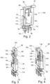
- Figures 2 to 4 illustrate a first embodiment of a fixing device 100 configured to fix a first-type component 101 whose body has a lower section and an upper section hereinafter referred respectively to a main portion 102 and an upper portion 104.
- the back surface 30 of the body is shared by both the main and upper portions.
- the main portion 102 has a substantially flat front face 106 configured to be in contact with the plate 40.
- the upper portion 104 has a substantially flat front face 108 which is substantially parallel to the back surface of the main portion.
- the thickness of the main portion is higher than the thickness of the upper portion such that the front face 108 of the upper portion is not in contact with the plate 40.
- the component of the first type comprises a well-known TO-220 package which comprises a metal tab with a hole.
- a metal tab with a hole.
- One of the face of the metal tab forms the back surface configured to be in contact with the heatsink.
- the plate 40 comprises abutments defining a receiving area for receiving the component.
- the abutments are in contact with at least a portion of a periphery of the component when the component is received in the receiving area.
- the abutments comprise a horizontal abutment 110 protruding from the face of the plate configured to be in contact with the component and configured to contact a bottom surface 54 of the component 12 when the component is received by the plate.
- the abutments comprise at least two vertical abutments 112, each protruding from the face of the plate 40 configured to be in contact with the component and each configured to contact a lateral surface 116 of the component when the component is received by the plate.
- the component is precisely positioned relative to the plate and cannot move relative to the plate. More particularly, any sliding movement downwardly in direction of the support is avoided and any tipping movement in a plane parallel to the plate is also avoided.
- the abutments can comprise another horizontal abutment arranged on the plate and configured to contact an upper surface 122 of the main portion 102 of the component when the component is received by the plate.
- the fixing device 10 comprises at least a fixing element configured to fix the component against the plate 40 of the fixing device.
- the fixing element comprises an element 66 configured to be arranged on the plate 40 to contact a periphery of the component, preferably the upper surface 122 of the main portion 102 of the component, when the component is received in the receiving area in order to maintain the component on the plate.
- the element 66 comprises a clamp 68 element having a C-shape configured to clamp the plate and to block the upper surface 122 of the main portion 102 of the component such that the clamp 68 forms the other horizontal abutment as described hereinbefore.
- the clamp comprises two elongate arm segments 130, 132 connected to each other by means of a joint section 134.
- the clamp is made in an elastic material and the arm segments 130, 132 are spaced to each other by a distance configured such that the joint section 134 exerts an elastic force causing the two arm segments 130, 132 to be pushed one against the other when the clamp clamps an upper portion of the plate.
- the clamp can further comprise a through-hole 136 receiving a pin 140 protruding from the plate when the clamp is mounted to block the clamp. More particularly, after the component is received by the receiving area of the plate in abutment against the horizontal and vertical abutments 110, 112, the clamp is installed on the plate by sliding in direction to the second end of the plate as illustrated in figure 3 . As one arm segment is in contact with the upper surface 122 of the main portion 102 of the component, the pin 140 is engaged with the corresponding through-hole 136 of the clamp in a lock position as illustrated in figure 4 .
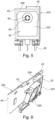
- Figures 5 and 6 illustrate a second embodiment of a fixing device 200 configured to fix a second-type component 202 whose body, on the contrary to the first-type component, comprises a single portion having substantially constant thickness between the front surface 34 and the back surface 30.
- the component of the second type comprises a well-known TO-246 package.
- Such component comprises a hole 64 extending from the front surface 34 to the back surface 30.
- the fixing element comprises a pin 62 extending from the face of the plate 40 configured to be in contact with the component.
- Said pin 62 is configured to be inserted in the hole 64 of the component 202 and dimensioned such that the component is maintained against the plate 40.
- the component is maintained by a friction force between said pin 62 and the hole 64.
- the pin 62 of the fixing element forms abutments defining a receiving area for receiving the component and avoiding sliding or tipping movements of the component when the component is mounted on the plate.
- the fixing device can comprise an upper horizontal abutment 204 configured to contact an upper surface 206 of the component when the component is received by the plate and thus avoiding tipping movements of the component when the component is mounted on the plate as illustrated on figure 10 .
- FIGS 7 to 9 represent other embodiments of a fixing device according to the invention, wherein the fixing device is configured to fix several components of one or different types against an element.
- figure 7 illustrate an embodiment of a fixing device 300 configured to fix five components of the first-type as described hereinbefore.
- the fixing device 400 is configured to fix six components: two of these components are of the first-type and the other four are of the second-type as described hereinbefore.
- FIG 9 Another example is illustrated on figure 9 , wherein the fixing device 500 according to the invention is configured to fix five components: two of these components are of the first-type and the others are of the second-type as described hereinbefore. Among the three components of the second-type, one is larger than the other ones and is advantageously maintained in position by an upper horizontal abutment as described hereinbefore.
- Another object of the invention relates to a method for assembling such a component against such an element thanks to a fixing device as described hereinbefore.
- the component 12 After providing the element 20, the or each component 12, the fixing device 10 and the support 16 on which the component is configured to be mounted, the component 12 is fixed against the plate 40 of the fixing device.
- the or each component 12 is positioned in a corresponding receiving area defined by the abutments of the plate 40.
- the or each component 12 is fixed against the plate 40 by a fixing element, by inserting a pin 62 in a hole 64 of the or each component 12 configured to maintain each component against the plate 40.
- the assembly formed by the plate and the component(s) are positioned relative to the support such that the free extremity of the or each rod of the component(s) are aligned with a corresponding through-hole of the support.
- the free extremity of the or each rod is thus introduced into the corresponding through-hole of the support such that the second end of the fixing device comes into contact with the support.
- the plate 40 is then pivoted around the second end 48 such that the back face 30 of the component contacts the side wall 32 of the element.
- the retaining element 42 of the fixing device 10 is engaged with the complementary retaining element 46 of the element 20 to a position in which a back face 30 of the component contacts and presses a side wall 32 of the element 20.
- the fixing device 10 further comprises a pressing device 80 as described hereinbefore, the pressing device 80 is installed for pressing the component against the side wall of the element.
- the pressing device is installed according to a vertical direction, i.e. a direction perpendicular to the top wall of the element in order to have one simple assembly method for several components and not conflict with neighbouring components during the assembly.
- a fixing device which is reliable, compact and can be easily assembled without the use of special tools.
Landscapes
- Connection Of Plates (AREA)
- Cooling Or The Like Of Electrical Apparatus (AREA)
Claims (18)
- Befestigungsvorrichtung (10) zum Befestigen einer Komponente (12), die dazu ausgelegt ist, auf einer Halterung (16) an einem aus der Halterung (16) hervorstehenden Element (20) montiert zu werden, wobei die Befestigungsvorrichtung umfasst:- eine Platte (40), die dazu ausgelegt ist, die Komponente (12) entlang einer Fläche (34) der Komponente (12) aufzunehmen, und- ein Rückhalteelement (42), das auf einem ersten Ende (44) der Platte (40) angeordnet und dazu ausgelegt ist, mit einem komplementären Rückhalteelement (46) des Elements (20) zusammenzuwirken, um die Komponente (12) an dem Element zu befestigen, wenn die Komponente auf der Halterung (16) montiert ist, wobei die Komponente (12) zwischen der Platte (40) und dem Element (20) angeordnet ist,wobei die Platte (40) ein zweites Ende (48), insbesondere gegenüber von dem ersten Ende (44), umfasst, das dazu ausgelegt ist, einen Abschnitt (52) der Komponente (12) derart aufzunehmen, dass der Abschnitt von der Platte (40) zum Einsetzen in eine Öffnung (50) in der Halterung (16) bei Montieren der Komponente auf der Halterung (16) hervorsteht, undgekennzeichnet durch das zweite Ende (48) der Platte, das einen Querschnitt aufweist, der mindestens einen zylindrischen Abschnitt (54) umfasst, der dazu ausgelegt ist, ein Schwenken der Platte (40) zwischen einer ersten Position, in der der zwischen der Platte und der Halterung gebildete Winkel ungleich Null ist, zu einer zweiten Position, in der die Platte im Wesentlichen senkrecht zu der Halterung steht, zu ermöglichen.
- Befestigungsvorrichtung nach Anspruch 1, ferner umfassend eine Andrückvorrichtung (80), die dazu ausgelegt ist, eine Kraft zum Andrücken der Komponente (12) an die Seitenwand (32) des Elements (20) auszuüben, wenn die Komponente (12) auf der Halterung (16) montiert ist.
- Befestigungsvorrichtung nach Anspruch 1 oder 2, wobei das zweite Ende (48) dazu ausgelegt ist, mindestens einen Stab (52) zu führen, der sich über eine untere Fläche (54) der Komponente (12) hinaus erstreckt und dazu ausgelegt ist, in eine Durchgangsöffnung (50) der Halterung (16) eingesetzt zu sein.
- Befestigungsvorrichtung nach einem der vorhergehenden Ansprüche, wobei eine Außenwand des zylindrischen Abschnitts (54) eine Schwenkfläche definiert, entlang derer die Platte (40) dazu ausgelegt ist, zwischen einer ersten Position, in der der zwischen der Platte und der Halterung gebildete Winkel ungleich Null ist, zu einer zweiten Position, in der die Platte im Wesentlichen senkrecht zu der Halterung steht, zu schwenken.
- Befestigungsvorrichtung nach einem der vorhergehenden Ansprüche, wobei die Platte (40) Auflager (110, 112; 62) umfasst, die einen Aufnahmebereich zum Aufnehmen der Komponente (12) bilden.
- Befestigungsvorrichtung nach dem vorhergehenden Anspruch, wobei die Auflager (110, 112) mit mindestens einem Abschnitt (54, 116, 122) eines Umfangs der Komponente (12) in Kontakt stehen, wenn die Komponente in dem Aufnahmebereich aufgenommen ist.
- Befestigungsvorrichtung nach einem der vorhergehenden Ansprüche, ferner umfassend mindestens ein Befestigungselement, das dazu ausgelegt ist, die Komponente an der Platte (40) der Befestigungsvorrichtung zu befestigen.
- Befestigungsvorrichtung nach dem vorhergehenden Anspruch, wobei:- die Komponente (12) eine Rückfläche (30), die dazu ausgelegt ist, mit der Seitenwand (32) des Elements (20) in Kontakt zu kommen, wenn die Komponente auf der Halterung montiert ist, eine Frontfläche (34), die der Rückfläche gegenüberliegt, und eine Öffnung (64), die sich von der Frontfläche zu der Rückfläche erstreckt, umfasst; und- das Befestigungselement einen Stift (62) umfasst, der sich von der Fläche der Platte (40) erstreckt, die dazu ausgelegt ist, mit der Komponente in Kontakt zu stehen, wobei der Stift (62) dazu ausgelegt ist, in die Öffnung (64) der Komponente eingesetzt und derart dimensioniert zu sein, dass die Komponente an der Platte gehalten wird.
- Befestigungsvorrichtung nach dem vorhergehenden Anspruch, wobei die Komponente durch eine Reibungskraft zwischen dem Stift (62) und der Öffnung (64) gehalten wird.
- Befestigungsvorrichtung nach einem der Ansprüche 7 bis 9, wobei das Befestigungselement ein Element (66) umfasst, das dazu ausgelegt ist, auf der Platte (40) derart angeordnet zu sein, dass es mit einem Umfang der Komponente in Kontakt kommt, wenn die Komponente in dem Aufnahmebereich aufgenommen ist, um die Komponente auf der Platte (40) zu halten.
- Befestigungsvorrichtung nach Anspruch 10, wobei das Element (66) ein Spannelement (68) mit einer C-Form umfasst, das dazu ausgelegt ist, die Platte (40) einzuspannen und ein oberes Ende (70) der Komponente zu blockieren.
- Befestigungsvorrichtung nach Anspruch 11, wobei das Spannelement (68) eine Durchgangsöffnung (136) umfasst, die einen von der Platte hervorstehenden Stift (140) aufnimmt, wenn das Spannelement montiert ist, um das Spannelement zu blockieren.
- Befestigungsvorrichtung nach einem der vorhergehenden Ansprüche, wobei das Rückhalteelement (42) an dem ersten Ende (44) der Platte eine elastische Lippe umfasst, die dazu ausgelegt ist, mit einer in dem komplementären Rückhalteelement (46) des Elements (20) enthaltenen Nut zusammenzuwirken.
- Befestigungsvorrichtung nach einem der vorhergehenden Ansprüche, wobei die Komponente eine Elektronikkomponente (14) ist, das Element eine Wärmesenke (22) ist und die Platte (40) eine Elektronikplatine ist, wobei die Elektronikkomponente (14) auf der Elektronikplatine (18) an der von der Elektronikplatine (14) hervorstehenden Wärmesenke (22) montiert ist.
- Befestigungsvorrichtung nach dem vorhergehenden Anspruch 14, wenn abhängig von Anspruch 3, zum Befestigen einer Elektronikkomponente (14) mit mindestens einer Elektrode, die den Stab (52) bildet.
- Verfahren zum Befestigen einer Komponente an einem Element auf einer Halterung, wobei das Element eine Befestigungsvorrichtung (10) nach einem der vorhergehenden Ansprüche 1 bis 15 umfasst, wobei die Befestigungsvorrichtung (10) ferner eine Andrückvorrichtung (80) umfasst, die dazu ausgelegt ist, eine Kraft zum Andrücken der Komponente (12) an die Seitenwand (32) des Elements (20) auszuüben, wenn die Komponente auf der Halterung (16) montiert ist, wobei das Verfahren mindestens die folgenden Schritte umfasst:a) Bereitstellen des Elements (12), der Komponente (20), der Befestigungsvorrichtung (10) und der Halterung (16), auf der die Komponente ausgelegt ist, montiert zu sein;b) Befestigen der Komponente (12) an der Platte (40) der Befestigungsvorrichtung;c) Ineingriffbringen des Rückhalteelements (42) mit dem komplementären Rückhalteelement (46) des Elements (20) bis zu einer Position, in der eine Rückfläche (30) der Komponente mit einer Seitenwand (32) des Elements (20) in Kontakt kommt; undd) Andrücken der Komponente an die Seitenwand des Elements mit der Andrückvorrichtung nach dem Schritt zum Ineingriffbringen des Rückhalteelements der Platte mit dem komplementären Rückhalteelement des Elements.
- Verfahren zum Befestigen einer Komponente an einem Element nach Anspruch 16, wobei die Komponente (12) mindestens einen Stab (52) umfasst, der sich über eine untere Fläche (54) der Komponente hinaus erstreckt und dazu ausgelegt ist, in eine Durchgangsöffnung (50) der Halterung (16) eingesetzt zu sein, wobei das Verfahren ferner einen Schritt zum Einsetzen des oder jedes Stabs der Komponente in entsprechende Durchgangsöffnungen der Halterung vor dem Schritt zum Ineingriffbringen des Rückhalteelements der Platte mit dem komplementären Rückhalteelement des Elements umfasst.
- Verfahren zum Befestigen einer Komponente an einem Element nach Anspruch 17, wobei die Platte (40) ein zweites Ende (48), insbesondere gegenüber von dem ersten Ende (44), umfasst, und wobei der Schritt zum Einsetzen des oder jedes Stabs der Komponente in entsprechende Durchgangsöffnungen der Halterung mindestens die folgenden Schritte umfasst:- Positionieren der Befestigungsvorrichtung (10) derart, dass das freie äußerste Ende des oder jedes Stabs der Komponente mit einer entsprechenden Durchgangsöffnung der Halterung ausgerichtet wird;- Einführen des freien äußersten Endes des oder jedes Stabs der Komponente in eine entsprechende Durchgangsöffnung der Halterung derart, dass das zweite Ende der Befestigungsvorrichtung mit der Halterung in Kontakt kommt; und- Schwenken der Platte (40) der Befestigungsvorrichtung (10) um das zweite Ende derart, dass die Rückfläche (30) der Komponente mit der Seitenwand (32) des Elements in Kontakt kommt.
Priority Applications (2)
| Application Number | Priority Date | Filing Date | Title |
|---|---|---|---|
| EP15163928.3A EP3082159B1 (de) | 2015-04-16 | 2015-04-16 | Befestigungsvorrichtung zur befestigung einer komponente an einem element |
| HUE15163928A HUE067858T2 (hu) | 2015-04-16 | 2015-04-16 | Rögzítõberendezés alkatrésznek egy egységhez történõ rögzítésére |
Applications Claiming Priority (1)
| Application Number | Priority Date | Filing Date | Title |
|---|---|---|---|
| EP15163928.3A EP3082159B1 (de) | 2015-04-16 | 2015-04-16 | Befestigungsvorrichtung zur befestigung einer komponente an einem element |
Publications (2)
| Publication Number | Publication Date |
|---|---|
| EP3082159A1 EP3082159A1 (de) | 2016-10-19 |
| EP3082159B1 true EP3082159B1 (de) | 2024-05-22 |
Family
ID=53002515
Family Applications (1)
| Application Number | Title | Priority Date | Filing Date |
|---|---|---|---|
| EP15163928.3A Active EP3082159B1 (de) | 2015-04-16 | 2015-04-16 | Befestigungsvorrichtung zur befestigung einer komponente an einem element |
Country Status (2)
| Country | Link |
|---|---|
| EP (1) | EP3082159B1 (de) |
| HU (1) | HUE067858T2 (de) |
Citations (1)
| Publication number | Priority date | Publication date | Assignee | Title |
|---|---|---|---|---|
| FR2654156A3 (fr) * | 1989-11-03 | 1991-05-10 | Marelli Autronica | Unite electronique de commande, en particulier pour installations d'allumage et/ou d'injection electroniques de vehicules automobiles. |
Family Cites Families (3)
| Publication number | Priority date | Publication date | Assignee | Title |
|---|---|---|---|---|
| US4972294A (en) * | 1989-04-03 | 1990-11-20 | Motorola, Inc. | Heat sink clip assembly |
| DE9206934U1 (de) * | 1991-05-22 | 1992-07-16 | Siemens AG, 8000 München | Vorrichtung zur Befestigung von Bauelementen an Kühlkörpern |
| DE102010042211A1 (de) * | 2010-10-08 | 2012-04-12 | Eta Plus Electronic Gmbh | Kühlvorrichtung für Halbleiterbauelemente |
-
2015
- 2015-04-16 HU HUE15163928A patent/HUE067858T2/hu unknown
- 2015-04-16 EP EP15163928.3A patent/EP3082159B1/de active Active
Patent Citations (1)
| Publication number | Priority date | Publication date | Assignee | Title |
|---|---|---|---|---|
| FR2654156A3 (fr) * | 1989-11-03 | 1991-05-10 | Marelli Autronica | Unite electronique de commande, en particulier pour installations d'allumage et/ou d'injection electroniques de vehicules automobiles. |
Non-Patent Citations (1)
| Title |
|---|
| "THE MAX CLIP SYSTEM(TM)", 1 January 2005 (2005-01-01), pages 1 - 40, XP055042899, Retrieved from the Internet <URL:http://www.aavid.com/sites/default/files/literature/MaxClip-Extrusion-Profiles-Catalog.pdf> [retrieved on 20121101] * |
Also Published As
| Publication number | Publication date |
|---|---|
| HUE067858T2 (hu) | 2024-11-28 |
| EP3082159A1 (de) | 2016-10-19 |
Similar Documents
| Publication | Publication Date | Title |
|---|---|---|
| US10559905B2 (en) | Flexible press fit pins for semiconductor packages and related methods | |
| US8672718B2 (en) | Board connecting terminal and holding structure of circuit board | |
| CN106104022B (zh) | 用于安装设备、特别是家用电器的固定系统 | |
| US8727815B1 (en) | Compliant pin connector mounting system and method | |
| US9130309B2 (en) | Electrical connector | |
| JP4506456B2 (ja) | 回路基板への基板用端子の取付構造 | |
| EP2149932B1 (de) | Endgerät-plattenschaltung mit einem schiebeelement | |
| EP3349550B1 (de) | Befestigungsvorrichtung | |
| JP5551206B2 (ja) | 基板装置 | |
| JP6555028B2 (ja) | ケーブル圧着端子実装体 | |
| US20140299893A1 (en) | Conductive Connector For Use With Circuit Board, and LED Module Having the Same | |
| KR20150036695A (ko) | 도전성 클립 | |
| US7331818B2 (en) | Card connector assembly with reinforcing elements | |
| CN112956083A (zh) | 连接器以及连接器的制造方法 | |
| US11483921B2 (en) | Holder for thermally contacting an electronic component mounted on a circuit board and a cooling body | |
| KR101780363B1 (ko) | 기판 접속용 커넥터 | |
| KR20110043598A (ko) | 전기 회로 장치 | |
| JP6882932B2 (ja) | 電子部品の固定構造 | |
| EP3082159A1 (de) | Befestigungsvorrichtung zur befestigung einer komponente an einem element | |
| TWI597898B (zh) | 特別用於汽車控制裝置的直接插接元件 | |
| US7881061B2 (en) | Mounting device for mounting heat sink onto electronic component | |
| US10181664B2 (en) | Contact and connector | |
| EP3082158A1 (de) | Pressvorrichtung zum andrücken eines bauteils gegen ein element | |
| JP5911305B2 (ja) | コネクタ装置 | |
| JP4293705B2 (ja) | 電子部品固定構造及び電子部品固定具 |
Legal Events
| Date | Code | Title | Description |
|---|---|---|---|
| PUAI | Public reference made under article 153(3) epc to a published international application that has entered the european phase |
Free format text: ORIGINAL CODE: 0009012 |
|
| AK | Designated contracting states |
Kind code of ref document: A1 Designated state(s): AL AT BE BG CH CY CZ DE DK EE ES FI FR GB GR HR HU IE IS IT LI LT LU LV MC MK MT NL NO PL PT RO RS SE SI SK SM TR |
|
| AX | Request for extension of the european patent |
Extension state: BA ME |
|
| STAA | Information on the status of an ep patent application or granted ep patent |
Free format text: STATUS: REQUEST FOR EXAMINATION WAS MADE |
|
| 17P | Request for examination filed |
Effective date: 20170419 |
|
| RBV | Designated contracting states (corrected) |
Designated state(s): AL AT BE BG CH CY CZ DE DK EE ES FI FR GB GR HR HU IE IS IT LI LT LU LV MC MK MT NL NO PL PT RO RS SE SI SK SM TR |
|
| STAA | Information on the status of an ep patent application or granted ep patent |
Free format text: STATUS: EXAMINATION IS IN PROGRESS |
|
| 17Q | First examination report despatched |
Effective date: 20200123 |
|
| RAP3 | Party data changed (applicant data changed or rights of an application transferred) |
Owner name: VALEO SIEMENS EAUTOMOTIVE NORWAY AS |
|
| RAP1 | Party data changed (applicant data changed or rights of an application transferred) |
Owner name: VALEO SIEMENS EAUTOMOTIVE FRANCE SAS |
|
| P01 | Opt-out of the competence of the unified patent court (upc) registered |
Effective date: 20230629 |
|
| GRAP | Despatch of communication of intention to grant a patent |
Free format text: ORIGINAL CODE: EPIDOSNIGR1 |
|
| STAA | Information on the status of an ep patent application or granted ep patent |
Free format text: STATUS: GRANT OF PATENT IS INTENDED |
|
| INTG | Intention to grant announced |
Effective date: 20231218 |
|
| GRAS | Grant fee paid |
Free format text: ORIGINAL CODE: EPIDOSNIGR3 |
|
| GRAA | (expected) grant |
Free format text: ORIGINAL CODE: 0009210 |
|
| STAA | Information on the status of an ep patent application or granted ep patent |
Free format text: STATUS: THE PATENT HAS BEEN GRANTED |
|
| AK | Designated contracting states |
Kind code of ref document: B1 Designated state(s): AL AT BE BG CH CY CZ DE DK EE ES FI FR GB GR HR HU IE IS IT LI LT LU LV MC MK MT NL NO PL PT RO RS SE SI SK SM TR |
|
| REG | Reference to a national code |
Ref country code: GB Ref legal event code: FG4D |
|
| REG | Reference to a national code |
Ref country code: CH Ref legal event code: EP |
|
| REG | Reference to a national code |
Ref country code: DE Ref legal event code: R096 Ref document number: 602015088756 Country of ref document: DE |
|
| REG | Reference to a national code |
Ref country code: IE Ref legal event code: FG4D |
|
| REG | Reference to a national code |
Ref country code: LT Ref legal event code: MG9D |
|
| REG | Reference to a national code |
Ref country code: NL Ref legal event code: MP Effective date: 20240522 |
|
| PG25 | Lapsed in a contracting state [announced via postgrant information from national office to epo] |
Ref country code: IS Free format text: LAPSE BECAUSE OF FAILURE TO SUBMIT A TRANSLATION OF THE DESCRIPTION OR TO PAY THE FEE WITHIN THE PRESCRIBED TIME-LIMIT Effective date: 20240922 |
|
| PG25 | Lapsed in a contracting state [announced via postgrant information from national office to epo] |
Ref country code: BG Free format text: LAPSE BECAUSE OF FAILURE TO SUBMIT A TRANSLATION OF THE DESCRIPTION OR TO PAY THE FEE WITHIN THE PRESCRIBED TIME-LIMIT Effective date: 20240522 |
|
| PG25 | Lapsed in a contracting state [announced via postgrant information from national office to epo] |
Ref country code: HR Free format text: LAPSE BECAUSE OF FAILURE TO SUBMIT A TRANSLATION OF THE DESCRIPTION OR TO PAY THE FEE WITHIN THE PRESCRIBED TIME-LIMIT Effective date: 20240522 Ref country code: FI Free format text: LAPSE BECAUSE OF FAILURE TO SUBMIT A TRANSLATION OF THE DESCRIPTION OR TO PAY THE FEE WITHIN THE PRESCRIBED TIME-LIMIT Effective date: 20240522 |
|
| PG25 | Lapsed in a contracting state [announced via postgrant information from national office to epo] |
Ref country code: GR Free format text: LAPSE BECAUSE OF FAILURE TO SUBMIT A TRANSLATION OF THE DESCRIPTION OR TO PAY THE FEE WITHIN THE PRESCRIBED TIME-LIMIT Effective date: 20240823 |
|
| PG25 | Lapsed in a contracting state [announced via postgrant information from national office to epo] |
Ref country code: PT Free format text: LAPSE BECAUSE OF FAILURE TO SUBMIT A TRANSLATION OF THE DESCRIPTION OR TO PAY THE FEE WITHIN THE PRESCRIBED TIME-LIMIT Effective date: 20240923 |
|
| REG | Reference to a national code |
Ref country code: AT Ref legal event code: MK05 Ref document number: 1689482 Country of ref document: AT Kind code of ref document: T Effective date: 20240522 |
|
| PG25 | Lapsed in a contracting state [announced via postgrant information from national office to epo] |
Ref country code: NL Free format text: LAPSE BECAUSE OF FAILURE TO SUBMIT A TRANSLATION OF THE DESCRIPTION OR TO PAY THE FEE WITHIN THE PRESCRIBED TIME-LIMIT Effective date: 20240522 |
|
| PG25 | Lapsed in a contracting state [announced via postgrant information from national office to epo] |
Ref country code: ES Free format text: LAPSE BECAUSE OF FAILURE TO SUBMIT A TRANSLATION OF THE DESCRIPTION OR TO PAY THE FEE WITHIN THE PRESCRIBED TIME-LIMIT Effective date: 20240522 |
|
| PG25 | Lapsed in a contracting state [announced via postgrant information from national office to epo] |
Ref country code: AT Free format text: LAPSE BECAUSE OF FAILURE TO SUBMIT A TRANSLATION OF THE DESCRIPTION OR TO PAY THE FEE WITHIN THE PRESCRIBED TIME-LIMIT Effective date: 20240522 |
|
| PG25 | Lapsed in a contracting state [announced via postgrant information from national office to epo] |
Ref country code: PL Free format text: LAPSE BECAUSE OF FAILURE TO SUBMIT A TRANSLATION OF THE DESCRIPTION OR TO PAY THE FEE WITHIN THE PRESCRIBED TIME-LIMIT Effective date: 20240522 |
|
| PG25 | Lapsed in a contracting state [announced via postgrant information from national office to epo] |
Ref country code: LV Free format text: LAPSE BECAUSE OF FAILURE TO SUBMIT A TRANSLATION OF THE DESCRIPTION OR TO PAY THE FEE WITHIN THE PRESCRIBED TIME-LIMIT Effective date: 20240522 |
|
| PG25 | Lapsed in a contracting state [announced via postgrant information from national office to epo] |
Ref country code: PT Free format text: LAPSE BECAUSE OF FAILURE TO SUBMIT A TRANSLATION OF THE DESCRIPTION OR TO PAY THE FEE WITHIN THE PRESCRIBED TIME-LIMIT Effective date: 20240923 Ref country code: PL Free format text: LAPSE BECAUSE OF FAILURE TO SUBMIT A TRANSLATION OF THE DESCRIPTION OR TO PAY THE FEE WITHIN THE PRESCRIBED TIME-LIMIT Effective date: 20240522 Ref country code: NO Free format text: LAPSE BECAUSE OF FAILURE TO SUBMIT A TRANSLATION OF THE DESCRIPTION OR TO PAY THE FEE WITHIN THE PRESCRIBED TIME-LIMIT Effective date: 20240822 Ref country code: NL Free format text: LAPSE BECAUSE OF FAILURE TO SUBMIT A TRANSLATION OF THE DESCRIPTION OR TO PAY THE FEE WITHIN THE PRESCRIBED TIME-LIMIT Effective date: 20240522 Ref country code: LV Free format text: LAPSE BECAUSE OF FAILURE TO SUBMIT A TRANSLATION OF THE DESCRIPTION OR TO PAY THE FEE WITHIN THE PRESCRIBED TIME-LIMIT Effective date: 20240522 Ref country code: IS Free format text: LAPSE BECAUSE OF FAILURE TO SUBMIT A TRANSLATION OF THE DESCRIPTION OR TO PAY THE FEE WITHIN THE PRESCRIBED TIME-LIMIT Effective date: 20240922 Ref country code: HR Free format text: LAPSE BECAUSE OF FAILURE TO SUBMIT A TRANSLATION OF THE DESCRIPTION OR TO PAY THE FEE WITHIN THE PRESCRIBED TIME-LIMIT Effective date: 20240522 Ref country code: GR Free format text: LAPSE BECAUSE OF FAILURE TO SUBMIT A TRANSLATION OF THE DESCRIPTION OR TO PAY THE FEE WITHIN THE PRESCRIBED TIME-LIMIT Effective date: 20240823 Ref country code: FI Free format text: LAPSE BECAUSE OF FAILURE TO SUBMIT A TRANSLATION OF THE DESCRIPTION OR TO PAY THE FEE WITHIN THE PRESCRIBED TIME-LIMIT Effective date: 20240522 Ref country code: ES Free format text: LAPSE BECAUSE OF FAILURE TO SUBMIT A TRANSLATION OF THE DESCRIPTION OR TO PAY THE FEE WITHIN THE PRESCRIBED TIME-LIMIT Effective date: 20240522 Ref country code: BG Free format text: LAPSE BECAUSE OF FAILURE TO SUBMIT A TRANSLATION OF THE DESCRIPTION OR TO PAY THE FEE WITHIN THE PRESCRIBED TIME-LIMIT Effective date: 20240522 Ref country code: AT Free format text: LAPSE BECAUSE OF FAILURE TO SUBMIT A TRANSLATION OF THE DESCRIPTION OR TO PAY THE FEE WITHIN THE PRESCRIBED TIME-LIMIT Effective date: 20240522 Ref country code: RS Free format text: LAPSE BECAUSE OF FAILURE TO SUBMIT A TRANSLATION OF THE DESCRIPTION OR TO PAY THE FEE WITHIN THE PRESCRIBED TIME-LIMIT Effective date: 20240822 |
|
| REG | Reference to a national code |
Ref country code: HU Ref legal event code: AG4A Ref document number: E067858 Country of ref document: HU |
|
| PG25 | Lapsed in a contracting state [announced via postgrant information from national office to epo] |
Ref country code: DK Free format text: LAPSE BECAUSE OF FAILURE TO SUBMIT A TRANSLATION OF THE DESCRIPTION OR TO PAY THE FEE WITHIN THE PRESCRIBED TIME-LIMIT Effective date: 20240522 |
|
| PG25 | Lapsed in a contracting state [announced via postgrant information from national office to epo] |
Ref country code: EE Free format text: LAPSE BECAUSE OF FAILURE TO SUBMIT A TRANSLATION OF THE DESCRIPTION OR TO PAY THE FEE WITHIN THE PRESCRIBED TIME-LIMIT Effective date: 20240522 |
|
| PG25 | Lapsed in a contracting state [announced via postgrant information from national office to epo] |
Ref country code: CZ Free format text: LAPSE BECAUSE OF FAILURE TO SUBMIT A TRANSLATION OF THE DESCRIPTION OR TO PAY THE FEE WITHIN THE PRESCRIBED TIME-LIMIT Effective date: 20240522 |
|
| PG25 | Lapsed in a contracting state [announced via postgrant information from national office to epo] |
Ref country code: RO Free format text: LAPSE BECAUSE OF FAILURE TO SUBMIT A TRANSLATION OF THE DESCRIPTION OR TO PAY THE FEE WITHIN THE PRESCRIBED TIME-LIMIT Effective date: 20240522 Ref country code: SK Free format text: LAPSE BECAUSE OF FAILURE TO SUBMIT A TRANSLATION OF THE DESCRIPTION OR TO PAY THE FEE WITHIN THE PRESCRIBED TIME-LIMIT Effective date: 20240522 |
|
| PG25 | Lapsed in a contracting state [announced via postgrant information from national office to epo] |
Ref country code: SM Free format text: LAPSE BECAUSE OF FAILURE TO SUBMIT A TRANSLATION OF THE DESCRIPTION OR TO PAY THE FEE WITHIN THE PRESCRIBED TIME-LIMIT Effective date: 20240522 |
|
| PG25 | Lapsed in a contracting state [announced via postgrant information from national office to epo] |
Ref country code: SM Free format text: LAPSE BECAUSE OF FAILURE TO SUBMIT A TRANSLATION OF THE DESCRIPTION OR TO PAY THE FEE WITHIN THE PRESCRIBED TIME-LIMIT Effective date: 20240522 Ref country code: SK Free format text: LAPSE BECAUSE OF FAILURE TO SUBMIT A TRANSLATION OF THE DESCRIPTION OR TO PAY THE FEE WITHIN THE PRESCRIBED TIME-LIMIT Effective date: 20240522 Ref country code: RO Free format text: LAPSE BECAUSE OF FAILURE TO SUBMIT A TRANSLATION OF THE DESCRIPTION OR TO PAY THE FEE WITHIN THE PRESCRIBED TIME-LIMIT Effective date: 20240522 Ref country code: EE Free format text: LAPSE BECAUSE OF FAILURE TO SUBMIT A TRANSLATION OF THE DESCRIPTION OR TO PAY THE FEE WITHIN THE PRESCRIBED TIME-LIMIT Effective date: 20240522 Ref country code: DK Free format text: LAPSE BECAUSE OF FAILURE TO SUBMIT A TRANSLATION OF THE DESCRIPTION OR TO PAY THE FEE WITHIN THE PRESCRIBED TIME-LIMIT Effective date: 20240522 Ref country code: CZ Free format text: LAPSE BECAUSE OF FAILURE TO SUBMIT A TRANSLATION OF THE DESCRIPTION OR TO PAY THE FEE WITHIN THE PRESCRIBED TIME-LIMIT Effective date: 20240522 |
|
| PG25 | Lapsed in a contracting state [announced via postgrant information from national office to epo] |
Ref country code: IT Free format text: LAPSE BECAUSE OF FAILURE TO SUBMIT A TRANSLATION OF THE DESCRIPTION OR TO PAY THE FEE WITHIN THE PRESCRIBED TIME-LIMIT Effective date: 20240522 |
|
| REG | Reference to a national code |
Ref country code: DE Ref legal event code: R097 Ref document number: 602015088756 Country of ref document: DE |
|
| PLBE | No opposition filed within time limit |
Free format text: ORIGINAL CODE: 0009261 |
|
| STAA | Information on the status of an ep patent application or granted ep patent |
Free format text: STATUS: NO OPPOSITION FILED WITHIN TIME LIMIT |
|
| PG25 | Lapsed in a contracting state [announced via postgrant information from national office to epo] |
Ref country code: SI Free format text: LAPSE BECAUSE OF FAILURE TO SUBMIT A TRANSLATION OF THE DESCRIPTION OR TO PAY THE FEE WITHIN THE PRESCRIBED TIME-LIMIT Effective date: 20240522 |
|
| 26N | No opposition filed |
Effective date: 20250225 |
|
| PGFP | Annual fee paid to national office [announced via postgrant information from national office to epo] |
Ref country code: DE Payment date: 20250411 Year of fee payment: 11 |
|
| PGFP | Annual fee paid to national office [announced via postgrant information from national office to epo] |
Ref country code: HU Payment date: 20250403 Year of fee payment: 11 |
|
| PGFP | Annual fee paid to national office [announced via postgrant information from national office to epo] |
Ref country code: FR Payment date: 20250429 Year of fee payment: 11 |
|
| PG25 | Lapsed in a contracting state [announced via postgrant information from national office to epo] |
Ref country code: SE Free format text: LAPSE BECAUSE OF FAILURE TO SUBMIT A TRANSLATION OF THE DESCRIPTION OR TO PAY THE FEE WITHIN THE PRESCRIBED TIME-LIMIT Effective date: 20240522 |
|
| REG | Reference to a national code |
Ref country code: CH Ref legal event code: H13 Free format text: ST27 STATUS EVENT CODE: U-0-0-H10-H13 (AS PROVIDED BY THE NATIONAL OFFICE) Effective date: 20251125 |
|
| REG | Reference to a national code |
Ref country code: DE Ref legal event code: R079 Ref document number: 602015088756 Country of ref document: DE Free format text: PREVIOUS MAIN CLASS: H01L0023400000 Ipc: H10W0040600000 |
|
| PG25 | Lapsed in a contracting state [announced via postgrant information from national office to epo] |
Ref country code: LU Free format text: LAPSE BECAUSE OF NON-PAYMENT OF DUE FEES Effective date: 20250416 |
|
| PG25 | Lapsed in a contracting state [announced via postgrant information from national office to epo] |
Ref country code: MC Free format text: LAPSE BECAUSE OF FAILURE TO SUBMIT A TRANSLATION OF THE DESCRIPTION OR TO PAY THE FEE WITHIN THE PRESCRIBED TIME-LIMIT Effective date: 20240522 |
|
| GBPC | Gb: european patent ceased through non-payment of renewal fee |
Effective date: 20250416 |
|
| REG | Reference to a national code |
Ref country code: BE Ref legal event code: MM Effective date: 20250430 |
|
| PG25 | Lapsed in a contracting state [announced via postgrant information from national office to epo] |
Ref country code: GB Free format text: LAPSE BECAUSE OF NON-PAYMENT OF DUE FEES Effective date: 20250416 |
|
| PG25 | Lapsed in a contracting state [announced via postgrant information from national office to epo] |
Ref country code: BE Free format text: LAPSE BECAUSE OF NON-PAYMENT OF DUE FEES Effective date: 20250430 |
|
| PG25 | Lapsed in a contracting state [announced via postgrant information from national office to epo] |
Ref country code: CH Free format text: LAPSE BECAUSE OF NON-PAYMENT OF DUE FEES Effective date: 20250430 |
|
| PG25 | Lapsed in a contracting state [announced via postgrant information from national office to epo] |
Ref country code: IE Free format text: LAPSE BECAUSE OF NON-PAYMENT OF DUE FEES Effective date: 20250416 |