EP3081854A1 - Guide de lumière avec atténuation de lumière réduite - Google Patents
Guide de lumière avec atténuation de lumière réduite Download PDFInfo
- Publication number
- EP3081854A1 EP3081854A1 EP15163406.0A EP15163406A EP3081854A1 EP 3081854 A1 EP3081854 A1 EP 3081854A1 EP 15163406 A EP15163406 A EP 15163406A EP 3081854 A1 EP3081854 A1 EP 3081854A1
- Authority
- EP
- European Patent Office
- Prior art keywords
- light guide
- guide element
- cross
- section
- light
- Prior art date
- Legal status (The legal status is an assumption and is not a legal conclusion. Google has not performed a legal analysis and makes no representation as to the accuracy of the status listed.)
- Granted
Links
- 238000005452 bending Methods 0.000 claims abstract description 17
- 238000005286 illumination Methods 0.000 claims 1
- 230000003287 optical effect Effects 0.000 description 5
- 230000005540 biological transmission Effects 0.000 description 2
- 239000011248 coating agent Substances 0.000 description 2
- 238000000576 coating method Methods 0.000 description 2
- 230000008878 coupling Effects 0.000 description 2
- 238000010168 coupling process Methods 0.000 description 2
- 238000005859 coupling reaction Methods 0.000 description 2
- 239000000463 material Substances 0.000 description 2
- 230000007704 transition Effects 0.000 description 2
- 238000010521 absorption reaction Methods 0.000 description 1
- POIUWJQBRNEFGX-XAMSXPGMSA-N cathelicidin Chemical compound C([C@@H](C(=O)N[C@@H](CCCNC(N)=N)C(=O)N[C@@H](CCCCN)C(=O)N[C@@H](CO)C(=O)N[C@@H](CCCCN)C(=O)N[C@@H](CCC(O)=O)C(=O)N[C@@H](CCCCN)C(=O)N[C@@H]([C@@H](C)CC)C(=O)NCC(=O)N[C@@H](CCCCN)C(=O)N[C@@H](CCC(O)=O)C(=O)N[C@@H](CC=1C=CC=CC=1)C(=O)N[C@@H](CCCCN)C(=O)N[C@@H](CCCNC(N)=N)C(=O)N[C@@H]([C@@H](C)CC)C(=O)N[C@@H](C(C)C)C(=O)N[C@@H](CCC(N)=O)C(=O)N[C@@H](CCCNC(N)=N)C(=O)N[C@@H]([C@@H](C)CC)C(=O)N[C@@H](CCCCN)C(=O)N[C@@H](CC(O)=O)C(=O)N[C@@H](CC=1C=CC=CC=1)C(=O)N[C@@H](CC(C)C)C(=O)N[C@@H](CCCNC(N)=N)C(=O)N[C@@H](CC(N)=O)C(=O)N[C@@H](CC(C)C)C(=O)N[C@@H](C(C)C)C(=O)N1[C@@H](CCC1)C(=O)N[C@@H](CCCNC(N)=N)C(=O)N[C@@H]([C@@H](C)O)C(=O)N[C@@H](CCC(O)=O)C(=O)N[C@@H](CO)C(O)=O)NC(=O)[C@H](CC=1C=CC=CC=1)NC(=O)[C@H](CC(O)=O)NC(=O)CNC(=O)[C@H](CC(C)C)NC(=O)[C@@H](N)CC(C)C)C1=CC=CC=C1 POIUWJQBRNEFGX-XAMSXPGMSA-N 0.000 description 1
- 229920003229 poly(methyl methacrylate) Polymers 0.000 description 1
- 239000004926 polymethyl methacrylate Substances 0.000 description 1
- 230000005855 radiation Effects 0.000 description 1
- 238000004088 simulation Methods 0.000 description 1
Images


Classifications
-
- G—PHYSICS
- G02—OPTICS
- G02B—OPTICAL ELEMENTS, SYSTEMS OR APPARATUS
- G02B6/00—Light guides; Structural details of arrangements comprising light guides and other optical elements, e.g. couplings
- G02B6/0001—Light guides; Structural details of arrangements comprising light guides and other optical elements, e.g. couplings specially adapted for lighting devices or systems
- G02B6/0005—Light guides; Structural details of arrangements comprising light guides and other optical elements, e.g. couplings specially adapted for lighting devices or systems the light guides being of the fibre type
- G02B6/001—Light guides; Structural details of arrangements comprising light guides and other optical elements, e.g. couplings specially adapted for lighting devices or systems the light guides being of the fibre type the light being emitted along at least a portion of the lateral surface of the fibre
-
- B—PERFORMING OPERATIONS; TRANSPORTING
- B60—VEHICLES IN GENERAL
- B60Q—ARRANGEMENT OF SIGNALLING OR LIGHTING DEVICES, THE MOUNTING OR SUPPORTING THEREOF OR CIRCUITS THEREFOR, FOR VEHICLES IN GENERAL
- B60Q1/00—Arrangement of optical signalling or lighting devices, the mounting or supporting thereof or circuits therefor
- B60Q1/26—Arrangement of optical signalling or lighting devices, the mounting or supporting thereof or circuits therefor the devices being primarily intended to indicate the vehicle, or parts thereof, or to give signals, to other traffic
- B60Q1/2661—Arrangement of optical signalling or lighting devices, the mounting or supporting thereof or circuits therefor the devices being primarily intended to indicate the vehicle, or parts thereof, or to give signals, to other traffic mounted on parts having other functions
- B60Q1/2665—Arrangement of optical signalling or lighting devices, the mounting or supporting thereof or circuits therefor the devices being primarily intended to indicate the vehicle, or parts thereof, or to give signals, to other traffic mounted on parts having other functions on rear-view mirrors
-
- F—MECHANICAL ENGINEERING; LIGHTING; HEATING; WEAPONS; BLASTING
- F21—LIGHTING
- F21S—NON-PORTABLE LIGHTING DEVICES; SYSTEMS THEREOF; VEHICLE LIGHTING DEVICES SPECIALLY ADAPTED FOR VEHICLE EXTERIORS
- F21S43/00—Signalling devices specially adapted for vehicle exteriors, e.g. brake lamps, direction indicator lights or reversing lights
- F21S43/20—Signalling devices specially adapted for vehicle exteriors, e.g. brake lamps, direction indicator lights or reversing lights characterised by refractors, transparent cover plates, light guides or filters
- F21S43/235—Light guides
- F21S43/236—Light guides characterised by the shape of the light guide
- F21S43/237—Light guides characterised by the shape of the light guide rod-shaped
-
- F—MECHANICAL ENGINEERING; LIGHTING; HEATING; WEAPONS; BLASTING
- F21—LIGHTING
- F21S—NON-PORTABLE LIGHTING DEVICES; SYSTEMS THEREOF; VEHICLE LIGHTING DEVICES SPECIALLY ADAPTED FOR VEHICLE EXTERIORS
- F21S43/00—Signalling devices specially adapted for vehicle exteriors, e.g. brake lamps, direction indicator lights or reversing lights
- F21S43/20—Signalling devices specially adapted for vehicle exteriors, e.g. brake lamps, direction indicator lights or reversing lights characterised by refractors, transparent cover plates, light guides or filters
- F21S43/235—Light guides
- F21S43/242—Light guides characterised by the emission area
- F21S43/245—Light guides characterised by the emission area emitting light from one or more of its major surfaces
-
- B—PERFORMING OPERATIONS; TRANSPORTING
- B60—VEHICLES IN GENERAL
- B60Q—ARRANGEMENT OF SIGNALLING OR LIGHTING DEVICES, THE MOUNTING OR SUPPORTING THEREOF OR CIRCUITS THEREFOR, FOR VEHICLES IN GENERAL
- B60Q3/00—Arrangement of lighting devices for vehicle interiors; Lighting devices specially adapted for vehicle interiors
- B60Q3/60—Arrangement of lighting devices for vehicle interiors; Lighting devices specially adapted for vehicle interiors characterised by optical aspects
- B60Q3/62—Arrangement of lighting devices for vehicle interiors; Lighting devices specially adapted for vehicle interiors characterised by optical aspects using light guides
- B60Q3/64—Arrangement of lighting devices for vehicle interiors; Lighting devices specially adapted for vehicle interiors characterised by optical aspects using light guides for a single lighting device
Definitions
- the invention relates to a light guide for use in an automotive environment, e.g. as part of a turn signal indicator and /or a lamp for illuminating an area inside or outside a vehicle, with optimized light attenuation properties.
- a light source does not have to be placed at the location where light should be emitted. Rather, the light of a light source can be transmitted via a light guide and decoupled from the latter at a desired area, which may be distant from the light source.
- the use of a light guide thus leads to more design flexibility.
- the light decoupling characteristics can be different from the light source, e.g. the light source may be a LED with a small radiation angle, whereas the light guide can decouple the light from the light source via a larger area.
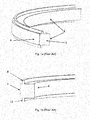
- FIG 1 A light guide according to the state of the art is illustrated in figure 1 .
- figure 1a shows a bent monobloc light guide 2 having a front surface 4 for the decoupling of light from the light guide and a back surface 6.
- the light guide 2 has connection elements 8, 10 for mechanically coupling the light guide to a respective receiving structure.
- the connection elements 8, 10 protrude from an upper and lower surface of the light guide straight and at right angles and are located close to the front surface 4.
- Figure 2 shows a light guide according to the state of the art assembled via connection elements 8, 10 between a housing 14, comprising a respective receiving structure, and a cap 16.
- connection elements 8, 10 between a housing 14, comprising a respective receiving structure, and a cap 16.
- the front surface 4 of the light guide forms part of the outer surface together with the cap 16.
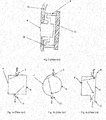
- Figure 3 shows the optical beam paths of different state of the art light guides with focus on the losses resulting in a high light attenuation.
- the arrows show exemplary light beams which enter the connection elements and are thus almost entirely lost.
- Figure 3a shows a light guide which is rectangular in cross section, wherein some light beams enter the connection elements, which protrude from the upper and lower surface of the light guide in the middle of its front and back surface.
- Figure 3b shows a circular light guide with different radii of the front and the back surface. In this case the radius of the front surface is greater than the radius of the back surface.
- light beams enter the connection elements, which protrude from the upper and lower surface of the light guide in the middle of the front and back surface.
- Figure 3c shows a rectangular light guide similar to the light guide of figure 3a , wherein the connection elements are located not in the middle of front and back surface but at the back surface of the light guide such that the connection elements and the back surface form a common straight surface.
- the invention aims at providing an improved light guide with reduced light attenuation.
- the invention provides a light guide for use in an automotive environment, which is adapted to receive light from a light source like a bulb or LED or gas discharge lamp or any other light source which can be used in an automotive environment.
- the light guide comprises at least one elongated light guide element for guiding light.
- the light guide element has a front surface and a back surface, wherein the front surface is for decoupling light from the light guide.
- the back surface preferably has good reflective properties and can be partially or entirely provided with a reflective material and/or small optics and/or may comprise optical features such as micro-structured surfaces and/or prisms and/or grooves. The mentioned features of the back surface may help to couple light out of the light guide via the front surface.
- the light guide comprises one or more connection elements which protrude from the light guide element.
- the connection element protrudes, in cross section, from an upper and/or lower surface of the light guide element and is adapted to mechanically connect the light guide to a respective receiving structure, e.g. provided in a rear view mirror of a vehicle.
- connection element close to the back surface of the light guide element, i.e. at least closer to the back surface than to the front surface, and the light guide element provides at least one convexly curved back surface. This may be true for parts of the light guide element or for the entire length of the light guide element. This may significantly lower the light attenuation as less light escapes via the connection element and more light may be reflected back into the light guide element.
- the back surface of the light guide element is convexly curved in order to reflect light from the back surface into the light guide element and minimize the overall light attenuation of the light guide.
- the convex bending radius of the back surface of the light guide element in cross section may be in the range of 0.6 * H L to 25 * H L .
- minimum length of the light guide element is to be understood throughout the description as the effective length, i.e. the total length which is optically active. For example, if the light guide element comprises multiple light guide element pieces, it is the total length of all pieces that is of interest.
- the width of the connection element should be rather small at the light guide element as compared to the maximum depth of the light guide element to avoid that much light enters the connection element and thus increases the overall light attenuation of the light guide.
- the thickness of the connection element can vary, e.g. it can be rather small at the vicinity of the light guide element and increase then in thickness with increasing distance from the light guide element. Also, the thickness can vary along the longitudinal axis of the light guide element.
- connection element and the back surface of the light guide element may form a common surface, which is convexly curved in cross section.
- the common surface may be formed by the side wall of the connection element which is closer to the back surface.
- the common surface may be without a kink, i.e. one smooth and convexly curved surface.
- the front surface of the light guide element may be substantially planar in cross-section.
- the front surface can be convex or concave.
- any combination is possible, e.g. to achieve different light decoupling characteristics in different light decoupling areas of the light guide.
- the light guide may be a monobloc light guide.
- the light guide can be a one piece light guide.
- the light guide element and the connection element can be integrally formed, e.g. molded. Further, the light guide may be bent along its longitudinal axis. In case the front surface of the light guide element is an outer surface there can be no further element or layer or there can be a coating such as a protection layer.
- connection elements of the light guide may protrude from the light guide element over at least 20% or at least 30% or at least 40% or at least 50% or at least 60% or at least 70% or at least 80% or at least 90 % of the minimum length of the light guide element.
- There can be two connection elements whereas a first connection element protrudes upwards from the upper surface of the light guide element and a second connection element protrudes downwards from the lower surface of the light guide element.
- the two connection elements may be different, e.g. the first one can protrude from the upper surface of the light guide element in an inclined way and the second connection element can protrude parallel to the front surface or at a right angle from the lower surface.
- the connection elements may be similar, e.g.
- connection element may protrude first in an inclined way and then parallel to the upper /lower surface.
- the connection element may also protrude in a bent way, e.g. so that one wall of the connection element forms a smooth common surface with the back surface.
- connection element can be located rather close to the back surface of the light guide element, but there can be a certain distance, e.g. forming a step between the back surface of the light guide element and the wall of the connection element which is closer to the back surface of the light guide element.
- connection element is inclined.
- the connection element can be inclined from the upper surface of a light guide, in cross section, between 280 degree (towards the front surface) and 15 degree (towards the back surface) and/or the reversed range from the lower surface, namely from the lower surface between 260 degree (towards the front surface) and 165 degree (towards the back surface).
- the front surface or a corresponding imaginary front surface line forms the 0 degree / 180 degree reference line.
- the mentioned inclination range is measured at or adjacent to or in the vicinity of the light guide element. At other locations, i.e. more distant from the light guide element, the connection element may have other inclinations, depending on the respective receiving structure.
- the invention further relates to a receiving structure comprised by a vehicle for receiving a light guide according to the invention.
- the invention relates to a rear view mirror for a vehicle, which comprises a receiving structure for receiving a light guide according to the invention.
- the receiving structure e.g. of the vehicle or the rear view mirror receives the light guide via the one or more connection elements.
- the front surface of the light guide element forms part of the outer surface of the rear view mirror.
- the light guide may form part of a device to illuminate an area and/or an object inside or outside a vehicle.
- the light guide may form part of a warning and/or indicating device such as a turn signal indicator and/or a position light and/or a stop lamp.
- cross-section of the light guide according to the invention may vary along the length of the light guide, e.g. the position of mechanical connections, shape of front, upper, lower and/or back surfaces.
- mechanical connection elements may be much more complex than the illustrated ones.
- Figure 4a shows an exemplary monobloc light guide according to the invention.
- the light guide element 2 is bent along its longitudinal axis and has a front surface 4 and a back surface 6.
- the front surface 4 is flat in cross section and is adapted to couple out light at least at certain areas.
- the back surface 6 is convexly curved and may comprise a reflective material and/or a scattering coating and/or small optics, e.g. for design purposes.
- Figure 4b shows connection elements 8 and 10 which protrude from the upper and lower surfaces of the light guide element 2.
- the connection elements 8, 10 protrude in an inclined manner, namely inclined towards the front surface 4.
- a second portion of the connection elements 8, 10, which is not in the vicinity of the light guide element 2 is parallel to the upper and lower surface of the light guide element 2.
- the back surface 6 and a portion of the connection elements 8, 10 form a common surface, which is convexly curved.
- Figure 5 shows a further exemplary one-piece light guide according to the invention, wherein the upper connection element 8, protruding from the upper surface of the light guide, is inclined towards the front surface 4 of the light guide element 2.
- the lower connection element 10 protrudes in a right angle from the lower surface of the light guide element 2.
- the connection elements 8, 10 are provided such that there is no distance between the connection elements 8, 10 and the back surface 6.
- the connection elements 8, 10 form a common surface with the back surface 6 of the light guide element 2.
- the transition from the back surface 6 to the upper connection element 8 is smooth, i.e. without a kink, whereas the transition from the back surface 6 to the lower connection element 10 has a kink.
- Figure 6 shows a further exemplary monobloc light guide according to the invention similar to the one illustrated in figure 5 .
- the differences will be explained in the following.
- the upper connection element 8 is located such that there is a certain distance to the back surface 6 which results in a step 12. Further, the distance between the lower connection element 10 and the front surface 4 of the light guide element 2 is increased such that the lower connection element 10 is shifted into the convexly curved back surface 6. In addition, the radius of the convexly curved back surface 6 is smaller.
- Inclinations and orientations are preferably based on the center line (in cross section from the front surface to the back surface at the half maximum height) as illustrated in figures 5 and 6 in form of a dashed line.
- the inclination is also clear in case of a non-flat front surface or in case of non-flat or inclined upper and lower surfaces.
- the front surface or upper or lower surface can be used provided that the respective surface is flat.
- Figure 7 shows optical beam paths, illustrated as arrows, of exemplary one-piece light guides according to the invention.
- the light guides as illustrated in figures 7a, 7b and 7c have different convexly curved back surfaces 6, wherein the connection elements 8, 10 form a common and smooth surface with the back surface 6.
- the convexly curved back surface 6 shown in figure 7a has a rather large bending radius, i.e. is rather flat, whereas the back surface 6 shown in figure 7b has a smaller bending radius.
- the back surface 6 shown in figure 7c has the smallest bending radius from the light guides shown in figures 7a to 7c.
- Figure 7d shows a light guide, wherein the connection elements 8, 10 protrude inclined but straight from the upper and lower surfaces of the light guide element 2.
- connection elements 8, 10 protrude at a certain distance from the back surface 6.
- the connection elements 8, 10 as illustrated in figure 7e protrude in a right angle from the upper and lower surfaces of the light guide element 2, however, there is no distance between the connection elements 8, 10 and the back surface 6 like in figure 7d .
- the convexly curved back surface 6 in combination with the location of the connection elements 8, 10, namely close to the back surface 6, as well as a rather small width of the connection elements in relation to the depth of the light guide element 2, helps to avoid that light enters the connection elements 8, 10. Also, as can be taken from figures 7d and 7e , it is advantageous to locate the connection elements as close to the back surface 6 as possible to minimize light attenuation.
- Figures 8a to 8d show possible front and back surfaces 4, 6 of a light guide according to the invention.
- the front surface 4 can be convexly curved as illustrated in figure 8a or concavely as illustrated in figure 8b .
- the front surface 4 can be flat as illustrated in figures 8c and 8d .
- the light guide according to figure 8a the light guide tapers in cross section from the front surface 4 to the back surface 6 and the upper and lower surfaces of the light guide element 2 are inclined.
- figure 8b shows a light guide element which tapers from the back surface 6 towards the front surface 4. This can help to scatter or focus light to be decoupled from the light guide.
- the back surface 6 can have various convex shapes, e.g. can have smaller or larger bending radii or have two convexities as illustrated in figure 8d .
- Figure 9 shows an experimental setup with a light guide for the tests shown in figures 10 and 11 .
- Light is coupled into the light guide at a first end portion 18 and a detector is provided at a second end portion 20 of the light guide to determine light attenuation.
- the horizontal surfaces 21 of the connection elements of the light guide are set to be perfectly absorbing surfaces, i.e. these surfaces neither reflect nor transmit light.
- the attenuation is obtained via ray-optics simulations using Optis SPEOS CAA V5 Based, version 17.1 with the following parameters: Light source: circular area with 8 mm diameter; Lambertian emission; 590 nm wavelength (monochromatic); 0.1 mm distance to light guide.
- Light guide PMMA; Refractive index 1.49 at a wavelength of 590 nm; 4% absorption along 1 m at a wavelength of 590 nm; Geometry: Light guide: length: 200 mm; Height: 10 mm; Depth: 10 mm; Straight / Bent with bending radius of 200 mm; Connection elements: thickness: 1.5 mm; perfectly absorbing surfaces (only horizontal surfaces 21).
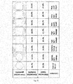
- Figure 10 shows different light guides and its light attenuation, i.e. the fraction of light which is coupled into the light guide and that does not reach the detector.
- the first test shows a light guide which is circular in cross section and has upper and lower connection elements protruding straight and at a right angle from the middle portion between front surface and back surface of the light guide.
- the light attenuation is 36.7% (straight) and 39.2% (bent).
- the second test shows a light guide which is similar to the light guide of the first test, however, the upper and lower connection elements are shifted towards the back surface of the light guide such that the back surface is flat.
- the light attenuation is 53.3% (straight) and 49.6% (bent).
- the third test shows a light guide which has a rectangular shape in cross section and has upper and lower connection elements protruding straight and at a right angle from the upper and lower surfaces.
- the connection elements are located at the middle portion, i.e. between the back and front surfaces of the light guide.
- the light attenuation is 42.9% (straight) and 46.8% (bent).
- the fourth test shows a light guide similar to the light guide of the third test, however, the connection elements are located at the side of the back surface of the light guide.
- the light attenuation is 43.5% (straight) and 38.4% (bent).
- the fifth test shows a light guide which has a rectangular shape in cross section and has upper and lower connection elements protruding inclined towards the front surface from the upper and lower surfaces.
- the connection elements are located adjacent to the back surface.
- the light attenuation is 50.5% (straight) and 41.9% (bent).
- bent light guides with mechanical connections adjacent to or at the back surface of the light guide reduce the light leakage as compared to geometries with central connections like in the third test.
- the sixth test shows a light guide similar to the light guide of the fifth test, however, the back surface is not flat but convexly curved.
- the light attenuation is 34.1% (straight) and 34.2% (bent).
- the seventh test shows a light guide which has a rectangular shape in cross section and has upper and lower connection elements protruding inclined and bent towards the front surface from the upper and lower surfaces.
- the connection elements are located adjacent to the back surface.
- the back surface of the light guide and the adjacent portions of the connection elements form a common convexly curved surface without a kink.
- the light attenuation is 30.6% (straight) and 30.2% (bent).
- the eights test shows a light guide similar to the fifth test, however, the connection elements protrude not inclined but straight and there is a distance between the back surface and connection elements. Hence, the back surface of the light guide does not form a smooth surface with the connection elements like in the seventh test.
- the light attenuation is 35.6% (straight) and 35.8% (bent).
- cross-section geometries with mechanical connections close to a convexly curved back surface provide a reduced light leakage as compared to state-of the art geometries.
- the light leakage is reduced both for straight and bent light guides.
- Figure 11 shows attenuation values of a light guide depending on geometrical relationships, wherein
- the longitudinal bending radius is 200 mm and in figure 11b the longitudinal bending radius is 100 mm and 400 mm, respectively.
- the grey shaded areas show geometric relationships with a significant improvement of the light transmission, i.e. low light attenuation.
- there is an optimum transmission of light in a certain geometric range which strongly depends on the convex bending radius of the back surface 6 of the light guide.
- the convex bending radius of the back surface 6 is preferably in the range of 0.6 * H L to 25 * H L .
- the relationship B/H + B/(10*D) is preferably in the range of 0.65 to 30.
Priority Applications (1)
| Application Number | Priority Date | Filing Date | Title |
|---|---|---|---|
| EP15163406.0A EP3081854B1 (fr) | 2015-04-13 | 2015-04-13 | Guide de lumière avec atténuation de lumière réduite |
Applications Claiming Priority (1)
| Application Number | Priority Date | Filing Date | Title |
|---|---|---|---|
| EP15163406.0A EP3081854B1 (fr) | 2015-04-13 | 2015-04-13 | Guide de lumière avec atténuation de lumière réduite |
Publications (2)
| Publication Number | Publication Date |
|---|---|
| EP3081854A1 true EP3081854A1 (fr) | 2016-10-19 |
| EP3081854B1 EP3081854B1 (fr) | 2019-03-13 |
Family
ID=52824158
Family Applications (1)
| Application Number | Title | Priority Date | Filing Date |
|---|---|---|---|
| EP15163406.0A Active EP3081854B1 (fr) | 2015-04-13 | 2015-04-13 | Guide de lumière avec atténuation de lumière réduite |
Country Status (1)
| Country | Link |
|---|---|
| EP (1) | EP3081854B1 (fr) |
Cited By (4)
| Publication number | Priority date | Publication date | Assignee | Title |
|---|---|---|---|---|
| EP3539824A1 (fr) * | 2018-03-15 | 2019-09-18 | NIO Nextev Limited | Élément de carrosserie de véhicule comprenant un guide de lumière |
| CN110388620A (zh) * | 2018-04-23 | 2019-10-29 | 株式会社小糸制作所 | 一种导光体 |
| CN110469815A (zh) * | 2018-05-09 | 2019-11-19 | 株式会社小糸制作所 | 导光体 |
| US11919443B1 (en) | 2023-02-23 | 2024-03-05 | Valeo Vision | Light guide |
Citations (7)
| Publication number | Priority date | Publication date | Assignee | Title |
|---|---|---|---|---|
| US20120069592A1 (en) * | 2010-09-17 | 2012-03-22 | Koito Manufacturing Co., Ltd. | Vehicular lamp |
| FR2964917A1 (fr) * | 2010-09-20 | 2012-03-23 | Webasto Systemes Carrosserie | Elcairage d'ambiance integre a des systemes de toit ouvrant ou d'occultation. |
| US20120170304A1 (en) * | 2009-09-18 | 2012-07-05 | Joerg Roberto Purfuerst | Connector |
| DE202012104086U1 (de) * | 2012-10-24 | 2012-11-19 | Wilhelm Koch Gmbh | Stabförmige Leuchte |
| WO2013104345A1 (fr) * | 2012-01-11 | 2013-07-18 | ŠKODA AUTO a.s. | Guide de lumière |
| US20140078764A1 (en) * | 2012-09-14 | 2014-03-20 | Koito Manufacturing Co., Ltd. | Vehicular Lamp |
| US20150009707A1 (en) * | 2008-07-18 | 2015-01-08 | 3M Innovative Properties Company | Lighting Device Comprising A Light Guide and a Support |
Family Cites Families (4)
| Publication number | Priority date | Publication date | Assignee | Title |
|---|---|---|---|---|
| DE102005013682B4 (de) * | 2005-03-18 | 2010-07-08 | SMR Patents S.à.r.l. | Außenrückblickspiegel von Fahrzeugen, vorzugsweise von Kraftfahrzeugen |
| JP5603571B2 (ja) * | 2009-06-05 | 2014-10-08 | 株式会社小糸製作所 | 車両用灯具 |
| JP5469965B2 (ja) * | 2009-09-04 | 2014-04-16 | 株式会社小糸製作所 | サイドターンシグナルランプ |
| CN203686831U (zh) * | 2013-05-09 | 2014-07-02 | 东芝照明技术株式会社 | 车辆用照明装置 |
-
2015
- 2015-04-13 EP EP15163406.0A patent/EP3081854B1/fr active Active
Patent Citations (7)
| Publication number | Priority date | Publication date | Assignee | Title |
|---|---|---|---|---|
| US20150009707A1 (en) * | 2008-07-18 | 2015-01-08 | 3M Innovative Properties Company | Lighting Device Comprising A Light Guide and a Support |
| US20120170304A1 (en) * | 2009-09-18 | 2012-07-05 | Joerg Roberto Purfuerst | Connector |
| US20120069592A1 (en) * | 2010-09-17 | 2012-03-22 | Koito Manufacturing Co., Ltd. | Vehicular lamp |
| FR2964917A1 (fr) * | 2010-09-20 | 2012-03-23 | Webasto Systemes Carrosserie | Elcairage d'ambiance integre a des systemes de toit ouvrant ou d'occultation. |
| WO2013104345A1 (fr) * | 2012-01-11 | 2013-07-18 | ŠKODA AUTO a.s. | Guide de lumière |
| US20140078764A1 (en) * | 2012-09-14 | 2014-03-20 | Koito Manufacturing Co., Ltd. | Vehicular Lamp |
| DE202012104086U1 (de) * | 2012-10-24 | 2012-11-19 | Wilhelm Koch Gmbh | Stabförmige Leuchte |
Cited By (4)
| Publication number | Priority date | Publication date | Assignee | Title |
|---|---|---|---|---|
| EP3539824A1 (fr) * | 2018-03-15 | 2019-09-18 | NIO Nextev Limited | Élément de carrosserie de véhicule comprenant un guide de lumière |
| CN110388620A (zh) * | 2018-04-23 | 2019-10-29 | 株式会社小糸制作所 | 一种导光体 |
| CN110469815A (zh) * | 2018-05-09 | 2019-11-19 | 株式会社小糸制作所 | 导光体 |
| US11919443B1 (en) | 2023-02-23 | 2024-03-05 | Valeo Vision | Light guide |
Also Published As
| Publication number | Publication date |
|---|---|
| EP3081854B1 (fr) | 2019-03-13 |
Similar Documents
| Publication | Publication Date | Title |
|---|---|---|
| US7695179B2 (en) | Illuminating device | |
| EP3081854A1 (fr) | Guide de lumière avec atténuation de lumière réduite | |
| US8820991B2 (en) | Lighting or signalling device with optical guide for motor vehicles | |
| KR101565609B1 (ko) | 균일한 시준된 광을 생성하기 위한 컴팩트한 광학 시스템 및 렌즈 | |
| EP3021043B1 (fr) | Appareil d'éclairage et automobile dans laquelle est monté un appareil d'éclairage | |
| EP2948809B1 (fr) | Guide de lumière | |
| JP5336880B2 (ja) | 発光装置 | |
| CN107208866B (zh) | 具有补偿沿着光导的光的渐进性损耗的装置的光导 | |
| EP2653779A2 (fr) | Module lumineux et son dispositif de guidage de lumière | |
| US20180058656A1 (en) | Light emitting area extender | |
| US20100098377A1 (en) | Light confinement using diffusers | |
| TW201307918A (zh) | 具有解耦部分之光導引件及收集解耦光線之屏蔽件 | |
| KR20180036936A (ko) | 거리 측정 센서 조립체 | |
| JP4503497B2 (ja) | 照明装置及び表示装置 | |
| US10787111B2 (en) | Light-guiding optical system, especially for motor vehicles | |
| KR101500924B1 (ko) | 확산렌즈 및 이를 구비한 백라이트 | |
| US6607279B2 (en) | Light guiding plate | |
| EP3260763A1 (fr) | Dispositif d'éclairage pour véhicule | |
| JP5837281B2 (ja) | 照明装置または信号装置などの、自動車用等の光学装置 | |
| KR20200043435A (ko) | 세분된 입사 마이크로 광학 요소들을 구비한 마이크로 광학 시스템을 포함하는 자동차 조명 장치 | |
| CN103782085A (zh) | 光学装置,尤其是用于机动车辆的光学装置 | |
| EP2082166A1 (fr) | Dispositif d'éclairage | |
| US5626412A (en) | Lighting device for vehicle | |
| EP3474047A1 (fr) | Dispositif de projection laser | |
| US6023550A (en) | Backlight system for transmissive electro optical modulator |
Legal Events
| Date | Code | Title | Description |
|---|---|---|---|
| PUAI | Public reference made under article 153(3) epc to a published international application that has entered the european phase |
Free format text: ORIGINAL CODE: 0009012 |
|
| 17P | Request for examination filed |
Effective date: 20160912 |
|
| AK | Designated contracting states |
Kind code of ref document: A1 Designated state(s): AL AT BE BG CH CY CZ DE DK EE ES FI FR GB GR HR HU IE IS IT LI LT LU LV MC MK MT NL NO PL PT RO RS SE SI SK SM TR |
|
| AX | Request for extension of the european patent |
Extension state: BA ME |
|
| STAA | Information on the status of an ep patent application or granted ep patent |
Free format text: STATUS: EXAMINATION IS IN PROGRESS |
|
| 17Q | First examination report despatched |
Effective date: 20170411 |
|
| RAP1 | Party data changed (applicant data changed or rights of an application transferred) |
Owner name: SMR PATENTS S.A.R.L. |
|
| REG | Reference to a national code |
Ref country code: DE Ref legal event code: R079 Ref document number: 602015026163 Country of ref document: DE Free format text: PREVIOUS MAIN CLASS: F21V0008000000 Ipc: F21S0043237000 |
|
| GRAP | Despatch of communication of intention to grant a patent |
Free format text: ORIGINAL CODE: EPIDOSNIGR1 |
|
| STAA | Information on the status of an ep patent application or granted ep patent |
Free format text: STATUS: GRANT OF PATENT IS INTENDED |
|
| RIC1 | Information provided on ipc code assigned before grant |
Ipc: B60Q 1/26 20060101ALI20180928BHEP Ipc: F21V 8/00 20060101ALI20180928BHEP Ipc: F21S 43/237 20180101AFI20180928BHEP Ipc: F21S 43/245 20180101ALI20180928BHEP |
|
| INTG | Intention to grant announced |
Effective date: 20181016 |
|
| GRAS | Grant fee paid |
Free format text: ORIGINAL CODE: EPIDOSNIGR3 |
|
| GRAA | (expected) grant |
Free format text: ORIGINAL CODE: 0009210 |
|
| STAA | Information on the status of an ep patent application or granted ep patent |
Free format text: STATUS: THE PATENT HAS BEEN GRANTED |
|
| RIC1 | Information provided on ipc code assigned before grant |
Ipc: F21S 43/245 20180101ALI20180928BHEP Ipc: F21V 8/00 20060101ALI20180928BHEP Ipc: F21S 43/237 20180101AFI20180928BHEP Ipc: B60Q 1/26 20060101ALI20180928BHEP |
|
| AK | Designated contracting states |
Kind code of ref document: B1 Designated state(s): AL AT BE BG CH CY CZ DE DK EE ES FI FR GB GR HR HU IE IS IT LI LT LU LV MC MK MT NL NO PL PT RO RS SE SI SK SM TR |
|
| REG | Reference to a national code |
Ref country code: GB Ref legal event code: FG4D |
|
| REG | Reference to a national code |
Ref country code: CH Ref legal event code: EP Ref country code: AT Ref legal event code: REF Ref document number: 1108198 Country of ref document: AT Kind code of ref document: T Effective date: 20190315 |
|
| REG | Reference to a national code |
Ref country code: IE Ref legal event code: FG4D |
|
| REG | Reference to a national code |
Ref country code: DE Ref legal event code: R096 Ref document number: 602015026163 Country of ref document: DE |
|
| REG | Reference to a national code |
Ref country code: NL Ref legal event code: MP Effective date: 20190313 |
|
| REG | Reference to a national code |
Ref country code: LT Ref legal event code: MG4D |
|
| PG25 | Lapsed in a contracting state [announced via postgrant information from national office to epo] |
Ref country code: FI Free format text: LAPSE BECAUSE OF FAILURE TO SUBMIT A TRANSLATION OF THE DESCRIPTION OR TO PAY THE FEE WITHIN THE PRESCRIBED TIME-LIMIT Effective date: 20190313 Ref country code: LT Free format text: LAPSE BECAUSE OF FAILURE TO SUBMIT A TRANSLATION OF THE DESCRIPTION OR TO PAY THE FEE WITHIN THE PRESCRIBED TIME-LIMIT Effective date: 20190313 Ref country code: SE Free format text: LAPSE BECAUSE OF FAILURE TO SUBMIT A TRANSLATION OF THE DESCRIPTION OR TO PAY THE FEE WITHIN THE PRESCRIBED TIME-LIMIT Effective date: 20190313 Ref country code: NO Free format text: LAPSE BECAUSE OF FAILURE TO SUBMIT A TRANSLATION OF THE DESCRIPTION OR TO PAY THE FEE WITHIN THE PRESCRIBED TIME-LIMIT Effective date: 20190613 |
|
| PG25 | Lapsed in a contracting state [announced via postgrant information from national office to epo] |
Ref country code: RS Free format text: LAPSE BECAUSE OF FAILURE TO SUBMIT A TRANSLATION OF THE DESCRIPTION OR TO PAY THE FEE WITHIN THE PRESCRIBED TIME-LIMIT Effective date: 20190313 Ref country code: HR Free format text: LAPSE BECAUSE OF FAILURE TO SUBMIT A TRANSLATION OF THE DESCRIPTION OR TO PAY THE FEE WITHIN THE PRESCRIBED TIME-LIMIT Effective date: 20190313 Ref country code: LV Free format text: LAPSE BECAUSE OF FAILURE TO SUBMIT A TRANSLATION OF THE DESCRIPTION OR TO PAY THE FEE WITHIN THE PRESCRIBED TIME-LIMIT Effective date: 20190313 Ref country code: GR Free format text: LAPSE BECAUSE OF FAILURE TO SUBMIT A TRANSLATION OF THE DESCRIPTION OR TO PAY THE FEE WITHIN THE PRESCRIBED TIME-LIMIT Effective date: 20190614 Ref country code: BG Free format text: LAPSE BECAUSE OF FAILURE TO SUBMIT A TRANSLATION OF THE DESCRIPTION OR TO PAY THE FEE WITHIN THE PRESCRIBED TIME-LIMIT Effective date: 20190613 Ref country code: NL Free format text: LAPSE BECAUSE OF FAILURE TO SUBMIT A TRANSLATION OF THE DESCRIPTION OR TO PAY THE FEE WITHIN THE PRESCRIBED TIME-LIMIT Effective date: 20190313 |
|
| REG | Reference to a national code |
Ref country code: AT Ref legal event code: MK05 Ref document number: 1108198 Country of ref document: AT Kind code of ref document: T Effective date: 20190313 |
|
| PG25 | Lapsed in a contracting state [announced via postgrant information from national office to epo] |
Ref country code: AL Free format text: LAPSE BECAUSE OF FAILURE TO SUBMIT A TRANSLATION OF THE DESCRIPTION OR TO PAY THE FEE WITHIN THE PRESCRIBED TIME-LIMIT Effective date: 20190313 Ref country code: PT Free format text: LAPSE BECAUSE OF FAILURE TO SUBMIT A TRANSLATION OF THE DESCRIPTION OR TO PAY THE FEE WITHIN THE PRESCRIBED TIME-LIMIT Effective date: 20190713 Ref country code: CZ Free format text: LAPSE BECAUSE OF FAILURE TO SUBMIT A TRANSLATION OF THE DESCRIPTION OR TO PAY THE FEE WITHIN THE PRESCRIBED TIME-LIMIT Effective date: 20190313 Ref country code: ES Free format text: LAPSE BECAUSE OF FAILURE TO SUBMIT A TRANSLATION OF THE DESCRIPTION OR TO PAY THE FEE WITHIN THE PRESCRIBED TIME-LIMIT Effective date: 20190313 Ref country code: SK Free format text: LAPSE BECAUSE OF FAILURE TO SUBMIT A TRANSLATION OF THE DESCRIPTION OR TO PAY THE FEE WITHIN THE PRESCRIBED TIME-LIMIT Effective date: 20190313 Ref country code: IT Free format text: LAPSE BECAUSE OF FAILURE TO SUBMIT A TRANSLATION OF THE DESCRIPTION OR TO PAY THE FEE WITHIN THE PRESCRIBED TIME-LIMIT Effective date: 20190313 Ref country code: RO Free format text: LAPSE BECAUSE OF FAILURE TO SUBMIT A TRANSLATION OF THE DESCRIPTION OR TO PAY THE FEE WITHIN THE PRESCRIBED TIME-LIMIT Effective date: 20190313 Ref country code: EE Free format text: LAPSE BECAUSE OF FAILURE TO SUBMIT A TRANSLATION OF THE DESCRIPTION OR TO PAY THE FEE WITHIN THE PRESCRIBED TIME-LIMIT Effective date: 20190313 |
|
| PG25 | Lapsed in a contracting state [announced via postgrant information from national office to epo] |
Ref country code: SM Free format text: LAPSE BECAUSE OF FAILURE TO SUBMIT A TRANSLATION OF THE DESCRIPTION OR TO PAY THE FEE WITHIN THE PRESCRIBED TIME-LIMIT Effective date: 20190313 Ref country code: PL Free format text: LAPSE BECAUSE OF FAILURE TO SUBMIT A TRANSLATION OF THE DESCRIPTION OR TO PAY THE FEE WITHIN THE PRESCRIBED TIME-LIMIT Effective date: 20190313 |
|
| REG | Reference to a national code |
Ref country code: CH Ref legal event code: PL |
|
| REG | Reference to a national code |
Ref country code: DE Ref legal event code: R097 Ref document number: 602015026163 Country of ref document: DE |
|
| REG | Reference to a national code |
Ref country code: BE Ref legal event code: MM Effective date: 20190430 |
|
| PG25 | Lapsed in a contracting state [announced via postgrant information from national office to epo] |
Ref country code: IS Free format text: LAPSE BECAUSE OF FAILURE TO SUBMIT A TRANSLATION OF THE DESCRIPTION OR TO PAY THE FEE WITHIN THE PRESCRIBED TIME-LIMIT Effective date: 20190713 Ref country code: LU Free format text: LAPSE BECAUSE OF NON-PAYMENT OF DUE FEES Effective date: 20190413 Ref country code: AT Free format text: LAPSE BECAUSE OF FAILURE TO SUBMIT A TRANSLATION OF THE DESCRIPTION OR TO PAY THE FEE WITHIN THE PRESCRIBED TIME-LIMIT Effective date: 20190313 |
|
| PLBE | No opposition filed within time limit |
Free format text: ORIGINAL CODE: 0009261 |
|
| STAA | Information on the status of an ep patent application or granted ep patent |
Free format text: STATUS: NO OPPOSITION FILED WITHIN TIME LIMIT |
|
| PG25 | Lapsed in a contracting state [announced via postgrant information from national office to epo] |
Ref country code: DK Free format text: LAPSE BECAUSE OF FAILURE TO SUBMIT A TRANSLATION OF THE DESCRIPTION OR TO PAY THE FEE WITHIN THE PRESCRIBED TIME-LIMIT Effective date: 20190313 Ref country code: LI Free format text: LAPSE BECAUSE OF NON-PAYMENT OF DUE FEES Effective date: 20190430 Ref country code: MC Free format text: LAPSE BECAUSE OF FAILURE TO SUBMIT A TRANSLATION OF THE DESCRIPTION OR TO PAY THE FEE WITHIN THE PRESCRIBED TIME-LIMIT Effective date: 20190313 Ref country code: CH Free format text: LAPSE BECAUSE OF NON-PAYMENT OF DUE FEES Effective date: 20190430 |
|
| 26N | No opposition filed |
Effective date: 20191216 |
|
| PG25 | Lapsed in a contracting state [announced via postgrant information from national office to epo] |
Ref country code: SI Free format text: LAPSE BECAUSE OF FAILURE TO SUBMIT A TRANSLATION OF THE DESCRIPTION OR TO PAY THE FEE WITHIN THE PRESCRIBED TIME-LIMIT Effective date: 20190313 Ref country code: BE Free format text: LAPSE BECAUSE OF NON-PAYMENT OF DUE FEES Effective date: 20190430 |
|
| REG | Reference to a national code |
Ref country code: DE Ref legal event code: R084 Ref document number: 602015026163 Country of ref document: DE |
|
| PG25 | Lapsed in a contracting state [announced via postgrant information from national office to epo] |
Ref country code: TR Free format text: LAPSE BECAUSE OF FAILURE TO SUBMIT A TRANSLATION OF THE DESCRIPTION OR TO PAY THE FEE WITHIN THE PRESCRIBED TIME-LIMIT Effective date: 20190313 |
|
| PG25 | Lapsed in a contracting state [announced via postgrant information from national office to epo] |
Ref country code: IE Free format text: LAPSE BECAUSE OF NON-PAYMENT OF DUE FEES Effective date: 20190413 |
|
| PG25 | Lapsed in a contracting state [announced via postgrant information from national office to epo] |
Ref country code: CY Free format text: LAPSE BECAUSE OF FAILURE TO SUBMIT A TRANSLATION OF THE DESCRIPTION OR TO PAY THE FEE WITHIN THE PRESCRIBED TIME-LIMIT Effective date: 20190313 |
|
| PG25 | Lapsed in a contracting state [announced via postgrant information from national office to epo] |
Ref country code: MT Free format text: LAPSE BECAUSE OF FAILURE TO SUBMIT A TRANSLATION OF THE DESCRIPTION OR TO PAY THE FEE WITHIN THE PRESCRIBED TIME-LIMIT Effective date: 20190313 Ref country code: HU Free format text: LAPSE BECAUSE OF FAILURE TO SUBMIT A TRANSLATION OF THE DESCRIPTION OR TO PAY THE FEE WITHIN THE PRESCRIBED TIME-LIMIT; INVALID AB INITIO Effective date: 20150413 |
|
| PG25 | Lapsed in a contracting state [announced via postgrant information from national office to epo] |
Ref country code: MK Free format text: LAPSE BECAUSE OF FAILURE TO SUBMIT A TRANSLATION OF THE DESCRIPTION OR TO PAY THE FEE WITHIN THE PRESCRIBED TIME-LIMIT Effective date: 20190313 |
|
| P01 | Opt-out of the competence of the unified patent court (upc) registered |
Effective date: 20230616 |
|
| PGFP | Annual fee paid to national office [announced via postgrant information from national office to epo] |
Ref country code: FR Payment date: 20230417 Year of fee payment: 9 Ref country code: DE Payment date: 20230418 Year of fee payment: 9 |
|
| PGFP | Annual fee paid to national office [announced via postgrant information from national office to epo] |
Ref country code: GB Payment date: 20230420 Year of fee payment: 9 |