EP3081615A2 - Fugenabdichtung für eine fuge mit mindestens einer schicht einer bitumenhaltigen ersten und einer bitumenhaltigen zweiten masse - Google Patents
Fugenabdichtung für eine fuge mit mindestens einer schicht einer bitumenhaltigen ersten und einer bitumenhaltigen zweiten masse Download PDFInfo
- Publication number
- EP3081615A2 EP3081615A2 EP16165251.6A EP16165251A EP3081615A2 EP 3081615 A2 EP3081615 A2 EP 3081615A2 EP 16165251 A EP16165251 A EP 16165251A EP 3081615 A2 EP3081615 A2 EP 3081615A2
- Authority
- EP
- European Patent Office
- Prior art keywords
- mass
- joint
- nozzle
- layer
- weight
- Prior art date
- Legal status (The legal status is an assumption and is not a legal conclusion. Google has not performed a legal analysis and makes no representation as to the accuracy of the status listed.)
- Granted
Links
Images


Classifications
-
- C—CHEMISTRY; METALLURGY
- C08—ORGANIC MACROMOLECULAR COMPOUNDS; THEIR PREPARATION OR CHEMICAL WORKING-UP; COMPOSITIONS BASED THEREON
- C08L—COMPOSITIONS OF MACROMOLECULAR COMPOUNDS
- C08L95/00—Compositions of bituminous materials, e.g. asphalt, tar, pitch
-
- B—PERFORMING OPERATIONS; TRANSPORTING
- B05—SPRAYING OR ATOMISING IN GENERAL; APPLYING FLUENT MATERIALS TO SURFACES, IN GENERAL
- B05B—SPRAYING APPARATUS; ATOMISING APPARATUS; NOZZLES
- B05B1/00—Nozzles, spray heads or other outlets, with or without auxiliary devices such as valves, heating means
-
- C—CHEMISTRY; METALLURGY
- C04—CEMENTS; CONCRETE; ARTIFICIAL STONE; CERAMICS; REFRACTORIES
- C04B—LIME, MAGNESIA; SLAG; CEMENTS; COMPOSITIONS THEREOF, e.g. MORTARS, CONCRETE OR LIKE BUILDING MATERIALS; ARTIFICIAL STONE; CERAMICS; REFRACTORIES; TREATMENT OF NATURAL STONE
- C04B26/00—Compositions of mortars, concrete or artificial stone, containing only organic binders, e.g. polymer or resin concrete
- C04B26/02—Macromolecular compounds
- C04B26/26—Bituminous materials, e.g. tar, pitch
-
- E—FIXED CONSTRUCTIONS
- E01—CONSTRUCTION OF ROADS, RAILWAYS, OR BRIDGES
- E01C—CONSTRUCTION OF, OR SURFACES FOR, ROADS, SPORTS GROUNDS, OR THE LIKE; MACHINES OR AUXILIARY TOOLS FOR CONSTRUCTION OR REPAIR
- E01C11/00—Details of pavings
- E01C11/02—Arrangement or construction of joints; Methods of making joints; Packing for joints
- E01C11/04—Arrangement or construction of joints; Methods of making joints; Packing for joints for cement concrete paving
- E01C11/10—Packing of plastic or elastic materials, e.g. wood, resin
- E01C11/103—Joints with packings prepared only in situ; Materials therefor
-
- E—FIXED CONSTRUCTIONS
- E01—CONSTRUCTION OF ROADS, RAILWAYS, OR BRIDGES
- E01C—CONSTRUCTION OF, OR SURFACES FOR, ROADS, SPORTS GROUNDS, OR THE LIKE; MACHINES OR AUXILIARY TOOLS FOR CONSTRUCTION OR REPAIR
- E01C23/00—Auxiliary devices or arrangements for constructing, repairing, reconditioning, or taking-up road or like surfaces
- E01C23/06—Devices or arrangements for working the finished surface; Devices for repairing or reconditioning the surface of damaged paving; Recycling in place or on the road
- E01C23/09—Devices or arrangements for working the finished surface; Devices for repairing or reconditioning the surface of damaged paving; Recycling in place or on the road for forming cuts, grooves, or recesses, e.g. for making joints or channels for markings, for cutting-out sections to be removed; for cleaning, treating, or filling cuts, grooves, recesses, or fissures; for trimming paving edges
- E01C23/0966—Devices or arrangements for working the finished surface; Devices for repairing or reconditioning the surface of damaged paving; Recycling in place or on the road for forming cuts, grooves, or recesses, e.g. for making joints or channels for markings, for cutting-out sections to be removed; for cleaning, treating, or filling cuts, grooves, recesses, or fissures; for trimming paving edges for filling or priming, with or without working the surface of the filling or applying particulate material thereto, e.g. for filling the joints of stone-sett paving
- E01C23/0973—Devices or arrangements for working the finished surface; Devices for repairing or reconditioning the surface of damaged paving; Recycling in place or on the road for forming cuts, grooves, or recesses, e.g. for making joints or channels for markings, for cutting-out sections to be removed; for cleaning, treating, or filling cuts, grooves, recesses, or fissures; for trimming paving edges for filling or priming, with or without working the surface of the filling or applying particulate material thereto, e.g. for filling the joints of stone-sett paving with liquid or semi-liquid materials, e.g. crack sealants
-
- C—CHEMISTRY; METALLURGY
- C04—CEMENTS; CONCRETE; ARTIFICIAL STONE; CERAMICS; REFRACTORIES
- C04B—LIME, MAGNESIA; SLAG; CEMENTS; COMPOSITIONS THEREOF, e.g. MORTARS, CONCRETE OR LIKE BUILDING MATERIALS; ARTIFICIAL STONE; CERAMICS; REFRACTORIES; TREATMENT OF NATURAL STONE
- C04B2111/00—Mortars, concrete or artificial stone or mixtures to prepare them, characterised by specific function, property or use
- C04B2111/00474—Uses not provided for elsewhere in C04B2111/00
- C04B2111/00663—Uses not provided for elsewhere in C04B2111/00 as filling material for cavities or the like
- C04B2111/00672—Pointing or jointing materials
-
- C—CHEMISTRY; METALLURGY
- C04—CEMENTS; CONCRETE; ARTIFICIAL STONE; CERAMICS; REFRACTORIES
- C04B—LIME, MAGNESIA; SLAG; CEMENTS; COMPOSITIONS THEREOF, e.g. MORTARS, CONCRETE OR LIKE BUILDING MATERIALS; ARTIFICIAL STONE; CERAMICS; REFRACTORIES; TREATMENT OF NATURAL STONE
- C04B2111/00—Mortars, concrete or artificial stone or mixtures to prepare them, characterised by specific function, property or use
- C04B2111/00474—Uses not provided for elsewhere in C04B2111/00
- C04B2111/0075—Uses not provided for elsewhere in C04B2111/00 for road construction
-
- C—CHEMISTRY; METALLURGY
- C04—CEMENTS; CONCRETE; ARTIFICIAL STONE; CERAMICS; REFRACTORIES
- C04B—LIME, MAGNESIA; SLAG; CEMENTS; COMPOSITIONS THEREOF, e.g. MORTARS, CONCRETE OR LIKE BUILDING MATERIALS; ARTIFICIAL STONE; CERAMICS; REFRACTORIES; TREATMENT OF NATURAL STONE
- C04B2111/00—Mortars, concrete or artificial stone or mixtures to prepare them, characterised by specific function, property or use
- C04B2111/72—Repairing or restoring existing buildings or building materials
-
- C—CHEMISTRY; METALLURGY
- C08—ORGANIC MACROMOLECULAR COMPOUNDS; THEIR PREPARATION OR CHEMICAL WORKING-UP; COMPOSITIONS BASED THEREON
- C08K—Use of inorganic or non-macromolecular organic substances as compounding ingredients
- C08K3/00—Use of inorganic substances as compounding ingredients
- C08K3/18—Oxygen-containing compounds, e.g. metal carbonyls
- C08K3/20—Oxides; Hydroxides
- C08K3/22—Oxides; Hydroxides of metals
- C08K2003/2237—Oxides; Hydroxides of metals of titanium
- C08K2003/2241—Titanium dioxide
-
- E—FIXED CONSTRUCTIONS
- E02—HYDRAULIC ENGINEERING; FOUNDATIONS; SOIL SHIFTING
- E02D—FOUNDATIONS; EXCAVATIONS; EMBANKMENTS; UNDERGROUND OR UNDERWATER STRUCTURES
- E02D31/00—Protective arrangements for foundations or foundation structures; Ground foundation measures for protecting the soil or the subsoil water, e.g. preventing or counteracting oil pollution
-
- Y—GENERAL TAGGING OF NEW TECHNOLOGICAL DEVELOPMENTS; GENERAL TAGGING OF CROSS-SECTIONAL TECHNOLOGIES SPANNING OVER SEVERAL SECTIONS OF THE IPC; TECHNICAL SUBJECTS COVERED BY FORMER USPC CROSS-REFERENCE ART COLLECTIONS [XRACs] AND DIGESTS
- Y02—TECHNOLOGIES OR APPLICATIONS FOR MITIGATION OR ADAPTATION AGAINST CLIMATE CHANGE
- Y02W—CLIMATE CHANGE MITIGATION TECHNOLOGIES RELATED TO WASTEWATER TREATMENT OR WASTE MANAGEMENT
- Y02W30/00—Technologies for solid waste management
- Y02W30/50—Reuse, recycling or recovery technologies
- Y02W30/91—Use of waste materials as fillers for mortars or concrete
Definitions
- the present invention relates to a joint seal for a joint with at least one layer of at least one first bituminous composition and a second bitumen-containing and titania-containing composition for a joint seal, the use of such a titania-containing composition as well as a joint with a joint seal according to the invention and / or titania-containing composition.
- Bituminous masses as jointing material or for filling cracks are used in particular in road construction and related fields, for example also in the construction, repair or renovation of traffic routes.
- Bitumen is a relatively cheap product of petroleum distillation, which due to its elastic-plastic properties not only as a binder in asphalt, but in particular in an elastomer-modified, d.
- Polymer-modified form is used as a joint material or crack filling material.
- Bitumen-based grouts are used in particular as hot grout, but also as cold grout, or in the form of Bitumenfugenb for filling horizontally arranged joints and / or cracks. These are particularly in the " Additional technical conditions of contract and guidelines for joints in traffic areas, edition 2001 (ZTV Fug-StB 01 ) ".
- bituminous hotmelt casting compounds or bitumen joint tapes are filled or closed with bituminous hotmelt casting compounds or bitumen joint tapes.
- vertical joints are filled in particular with masses or bands which are based on polysulfides and / or polyurethanes. This is due to the fact that bituminous compounds, in particular hot potting compounds, are too low viscosity to be used in vertical joints and / or cracks, since these simply run out of them.
- Bitumen joint tapes are difficult to use in vertical joints and / or cracks due to the often specific geometry of the same, or because they also during insertion, even using primers or primers, not readily remain after insertion into a vertical joint in selbiger, but from this independently on the basis of its own weight dissolve.
- vertical joints can be found in the area of concrete protective walls on traffic routes.
- Concrete barriers are usually made of molded blocks and, for example, for noise protection, or for subdivisions of roadways, for example on highways or federal highways, used.
- concrete protective walls are first produced continuously and then joints introduced to create a compensation for movement and thus reduce possible tension.
- the corresponding stones are placed next to each other, forming a gap between opposite faces.
- the mentioned joints should be closed. Joint seals for vertical joints in particular concrete protective walls, for example, by inserting suitable joint tapes, possibly also with profile, but the above-mentioned problems occur.
- masses of polysulfides or polyurethanes can be used to close the joints, which, however, are relatively expensive compared to bituminous materials.
- a joint seal for a joint in particular in concrete parts, in concrete protection walls, with at least one layer of bitumen-containing first mass and at least one layer of a bituminous second mass, wherein the at least one layer of the second mass on the at least one layer the first mass is arranged and forms an exposed surface, wherein a ratio of a layer thickness of the first mass and the second mass in a range of about 250: 1 to about 1: 1 and wherein the second mass, in contrast to the first mass about 10 wt from about% to about 40% by weight, based on the total amount of the second mass, of titanium dioxide.
- the ratio of the layer thickness of the first mass and the second mass is in a range of about 50: 1 to about 2: 1, more preferably in a range of about 30: 1 to about 2.5: 1.
- the second mass titanium dioxide has a bulk density in a range of about 450 kg / m 3 to about 750 kg / m 3 , more preferably a bulk density in a range of about 520 kg / m 3 to about 660 kg / m 3 .
- the titanium dioxide is in powder form in the second mass.
- the relative scattering power according to DIN 53165 of the titanium dioxide used is preferably in a range from about 58 to about 75, preferably in a range from about 60 to about 68. More preferably, the titanium dioxide used in the second mass is not affected by further elements such as aluminum, Stabilized silicon or manganese. Preferably, the titanium dioxide-containing and bituminous second mass comprises about 15 wt .-% to about 35 wt .-%, more preferably about 20 wt .-% to about 30 wt .-%, each based on the total amount of the second composition of at least one titanium dioxide.
- bitumen Insofar as the term "bitumen” is used in the present application, a bitumen with a needle penetration at 25 ° C. in accordance with DIN EN 1426 (unit of measurement 0.1 mm) in a range from about 80 to about 300 is particularly preferred in the range of about 140 to about 250, more preferably in the range of about 160 to about 220. Bitumen is particularly preferably used, which is suitable for road construction, based on the DIN 1995-1.
- the bituminous first composition comprises at least one bitumen in an amount ranging from about 40% to about 65% by weight, more preferably from about 45% to about 58% by weight. , even more preferably in an amount ranging from about 42% to about 56% by weight.
- the titania-containing and bituminous second mass comprises bitumens in an amount ranging from about 30% to about 55%, more preferably in a range of about 33% to about 48% by weight.
- the term "elastomer” is understood to mean a polymer having a rubber-elastic behavior which can be repeatedly stretched at room temperature to at least two times its length and immediately resumes approximately the initial length after removal of the force required for the elongation.
- the at least one elastomer is selected from a group comprising styrene-butadiene copolymers, styrene-butadiene-styrene (block) copolymers, styrene-isoprene (block) copolymers, styrene-isoprene-styrene (Block) copolymers, butadiene rubbers, butyl rubbers, halogenated butyl rubbers and / or natural rubbers.
- the at least one elastomer can preferably be added to the mixture in the form of a flour, more preferably in the form of a gum powder.
- the grain size is in a range of> 0 mm to about 0.5 mm.
- the at least one elastomer in the form of a flour it can advantageously also be a mixture of different elastomers and, for example, a mixture comprising natural rubbers, styrene-butadiene rubbers, styrene-isoprene-styrene copolymers, styrene-isoprene copolymers, butadiene Rubbers and / or butyl rubbers or halogenated rubbers.
- the elastomer is a styrene-isoprene-styrene copolymer, especially when this is formed as a block copolymer, preferably in the form of a styrene-isoprene-styrene / styrene-isoprene block copolymer.
- the elastomer used is a mixture of a styrene-butadiene-styrene copolymer, optionally also block copolymers, and / or a styrene-isoprene-styrene copolymer or block copolymers in admixture with a flour, which is a recycle, preferably from automobile tires . and thereby represents a mixture of a natural rubber, a styrene-butadiene rubber, a butadiene rubber, a butyl rubber and / or a halogenated butyl rubber.
- the at least one elastomer is present in an amount of about 2 weight percent, preferably about 5 weight percent, to about 20 weight percent, more preferably in an amount of about 8 weight percent to about 16 weight percent %, more preferably in an amount of about 11% to about 15% by weight, used in the bituminous first mass, wherein the weight percentages are each based on the total amount of the first mass. More preferably, the at least one elastomer is included in the titania-containing and bituminous second mass in an amount ranging from about 3% to about 9% by weight, more preferably in an amount ranging from about 4% to about about 7.5 wt .-%, wherein the weight percentages are based on the total amount of the second mass.
- the composition according to the invention particularly preferably comprises the at least one elastomer, in particular formed as styrene-isoprene-styrene (block) copolymer and / or styrene-butadiene-styrene (block) copolymer, both in particular in the form of block copolymers from about 2.5% to about 10%, more preferably from about 5% to about 9%, by weight, as well as another elastomer on the base a flour obtained as a recycle preferred from automobile tires comprising a mixture of various elastomers as mentioned above in an amount of from about 3% to about 12% by weight, more preferably an amount of from about 5% to about about 8 wt .-%, on.
- the at least one pulverulent mineral filler in the context of the present invention is preferably selected from a group comprising silicates, phosphates and / or sulfates. More preferably, the powdered mineral filler is free of carbonate.
- the at least one pulverulent mineral filler is particularly preferably selected from a group comprising magnesium silicates, in particular a talc.
- the at least one powdered mineral filler can also be used in a mixture with, for example, a chlorite. More preferably, the at least one powdered mineral filler is present in an amount ranging from about 14% to about 30% by weight, more preferably in an amount ranging from about 15% to about 23% by weight.
- the at least one powdered mineral filler is present in the titania-containing and bituminous second mass in an amount ranging from about 9% to about 22% by weight, more preferably in an amount ranging from about 10% by weight. % to about 18 wt .-%, each based on the total amount of the second mass used.
- the first and the second composition according to the invention comprise at least one fibrous adjusting agent, which serves to adjust the strength, in particular the stability.
- the processing consistency of the first and second mass can be adjusted by means of this fibrous actuating means.
- the at least one fibrous adjusting agent is advantageously present in an amount in a range of about 1 wt .-% to about 4.5 wt .-%, more preferably in an amount in a range of about 1.6 wt .-% to about 3 wt .-%, each based on the total amount of the first mass, contained in this.
- the at least one fibrous sizing agent is advantageously present in the titania-containing and bituminous second mass in an amount ranging from about 0.75% to about 2.5% by weight, more preferably in an amount within a range of about 1% by weight .-% to about 2 wt .-%, each based on the total amount of the second mass used.
- the at least one fibrous actuating agent is selected from a group comprising cellulose, glass fibers and / or plastic fibers, and is particularly preferably from a group comprising cellulose fibers.
- the at least one adjusting agent preferably has an average fiber length in a range from about 500 ⁇ m to about 1500 ⁇ m, more preferably a fiber length in a range from about 800 ⁇ m to about 1500 ⁇ m. More preferably, the at least one fibrous actuator has an average fiber thickness in a range of about 20 microns to about 80 microns, more preferably one in a range of about 30 microns to about 60 microns.
- the first and second compositions furthermore comprise at least one polymer which differs from the at least one elastomer described above and is prepared from an olefin and in particular an ⁇ , ⁇ -unsaturated carboxylic acid and / or in particular ⁇ , ⁇ -unsaturated carboxylic acid anhydride.
- This is advantageously in an amount ranging from about 0.5% to about 2.8% by weight, more preferably from about 0.8% to about 2% by weight, even more preferably in from about 0.9% to about 1.4% by weight, in the first mass, wherein the weight percentages are each based on the total amount of the first mass.
- the at least one polymer is in an amount ranging from about 0.25 wt% to about 3 wt%, more preferably about 0.45 wt%. to about 1.2% by weight, more preferably in an amount ranging from about 0.5% to about 1% by weight, wherein the weight percentages are each based on the total amount of the second mass
- the polymer is made from an olefin selected from a group comprising ethylene and / or propylene or vinyl alcohol, and maleic anhydride.
- maleic anhydride for example, acrylic acid would also be possible. It is also possible to use ionomers of the stated polymers.
- copolymers of maleic anhydride copolymers or grafted polymers of maleic anhydride with propylene and / or ethylene used. It is possible to use random copolymers with a maleic anhydride content of ⁇ 50 mol% as well as alternating copolymers with a maleic anhydride content of 50 mol%. In this case, a variety of monomers of different structure can be used.
- the at least one polymer is used in the form of pastilles, with an average diameter in a range of about 7 mm to about 10 mm.
- the density of the polymer used is in a range from about 0.90 g / cm 3 to about 0.935 g / cm 3 , measured according to ISO 1183.
- Particularly preferred for the purposes of the present invention is a polymer Ethylene-maleic anhydride copolymer in the abovementioned percentages by weight, preferably as a random, but also as an alternating copolymer used, particularly preferably a grafted.
- the polymer used of ethylene and / or propylene and maleic anhydride or acrylic acid preferably has a Brookfield viscosity at a temperature of 140 ° C in a range of about 400 to about 3000 mPa * s, more preferably in a range of about 500 mPa * s up to about 2000 mPa * s, on.
- the polymer prepared from ethylene and / or propylene and maleic anhydride or acrylic acid has a drop point according to ASTM D3954 in a range of about 85 ° C to about 125 ° C, more preferably in a range of about 90 ° C to about 115 ° C measured, for example, with a drop point analysis system DP70 from Mettler-Toledo AG, Schwerzenbach, Switzerland.
- the at least one polymer advantageously serves as a compatibilizer, in particular to allow the incorporation of the at least one fibrous actuating agent, but also of the pulverulent mineral filler in the composition according to the invention.
- the softening point of the first and second masses is increased by the at least one polymer, or the melt viscosity thereof is reduced.
- the polymer used is thus similar to a wax advantageously used in the first and second mass, for which statements are made below.
- the first composition may comprise at least one wax in an amount ranging from about 0.5 wt% to about 3 wt%, more preferably in an amount ranging from about 1 wt% to about 2 wt .-%, each based on the total amount of the first mass.
- the second composition of the invention preferably comprises at least one wax in an amount ranging from about 0.5% to about 2.5% by weight, more preferably in an amount within a range of about 0.8% by weight. % to about 1.5 wt .-%, each based on the total amount of the second mass.
- the wax is particularly preferably selected from a group comprising Fischer-Tropsch waxes and / or montan waxes.
- the at least one wax is advantageously used to increase the softening point of the first, possibly the second mass or the reduction of the melt viscosity thereof.
- the first composition further advantageously comprises at least one plasticizer selected from the group of aliphatic and / or naphthenic oils in an amount ranging from about 5% to about 20% by weight, more preferably in an amount in one Range from about 8 wt .-% to about 15 wt .-%, each based on the total amount of the first mass.
- at least one plasticizer selected from the group of aliphatic and / or naphthenic oils in an amount ranging from about 5% to about 20% by weight, more preferably in an amount in one Range from about 8 wt .-% to about 15 wt .-%, each based on the total amount of the first mass.
- the titanium dioxide-containing and bituminous second composition according to the invention advantageously comprises at least one plasticizer selected from a group of aliphatic and / or naphthenic oils, in particular one identical to that which may be comprised by the first composition, in an amount in the range of about 3 , 5 wt .-% to about 15 wt .-%, more preferably in a range of about 5 wt .-% to about 12 wt .-%, each based on the total amount of the second mass.
- the first and / or second composition comprises at least one naphthenic process oil as plasticizer.
- the at least one plasticizer advantageously has a density at 25 ° C according to ISO 12185 in a range from about 0.89 kg / dm 3 to about 0.915 kg / dm 3 . It advantageously has a viscosity at 40 ° C according to ISO 3104 in a range of about 50 mm 2 / s (cSt), preferably about 130 mm 2 / s (cSt), to about 170 mm 2 / s (cSt), preferably to about 155 mm 2 / s (cSt), on.
- the first and / or second mass advantageously has a softening point according to DIN EN 1427 of greater than or equal to about 85 ° C., more preferably greater than or equal to about 90 ° C. More preferably, the first and / or second mass has a cone penetration according to DIN EN 13880-2 at 25 ° C in a range of about 40 to about 130 1/10 mm, more preferably in a range of about 50 to about 110 1 / 10 mm, on. More preferably, the first and / or second mass has an elastic resilience according to DIN EN 12880-3 of less than or equal to about 60%, more preferably less than or equal to about 50%.
- the first and / or second mass have the great advantage that they can be used due to their high stability even at temperatures of about 70 ° C or more, especially in the area of vertical joints and cracks. Due to their specific properties, the first and / or second masses can be used in horizontal as well as in vertical surfaces and also in connections of horizontal joints or cracks to vertical joints or cracks, so that incompatibility problems do not arise.
- the first and second masses can also advantageously be used in particular for concrete components, in particular concrete protective walls, or road surfaces, which are exposed to aggressive media, both for horizontal and vertical uses.
- the first and second masses can be used in crossed joints in asphalt and concrete surfaces, ie joints, but also cracks, which are run over by commercial vehicles such as tractors, trucks or cars.
- the first and second mass are resistant to aggressive media even over long periods of time. They are one-component and therefore easy to process. They are preferably heated or hot processed at temperatures in a range of about 90 ° C to about 200 ° C, preferably in a range of about 100 ° C to about 160 ° C.
- the first and the second mass are very compatible with each other.
- the first and the second mass are composed of identical constituents except for the titanium dioxide. More preferably, at least the at least one bitumen used and the at least one polymer used, more preferably additionally the at least one elastomer used, in the first and the second mass identical. Identical here means that the constituents have a chemically identical structure, more preferably also physically identical properties.
- the first and the second mass preferably fused together.
- a detachment of a layer of the second mass from a layer of the first mass arranged underneath is advantageously prevented. Even at room temperature, especially at elevated temperatures above about 40 ° C, preferably from about 50 ° C, an adhesion takes place.
- the joint seal according to the invention advantageously protects an internal reinforcement of concrete parts, in particular concrete protective walls, in particular against corrosion.
- the at least one layer of the second mass completely covers the at least one layer of the first mass.
- the layer of the second mass preferably has a greater width than the layer of the first mass whose width is predetermined by a width of the joint.
- the covering by the second mass may in particular be such that the at least one layer of the second mass above the joint, d. h, above an upper joint edge of the same, is arranged, and thus adjacent to the upper edge of the joint surface, for. B. a concrete part, in particular a concrete protective wall, covered, for. B. about 1 mm to about 5 mm, especially on both sides of the joint.
- the at least one layer of the second mass may be received in an expansion of the joint at its upper joint edge.
- the second mass may be formed as a band or as a shapeless mass.
- a band she can z. B. over a introduced in a joint at least one layer of the first mass, wherein an adhesion of the layers, preferably at elevated temperatures, takes place, wherein a residual heat of the first mass or a temperature of z. B. 23 ° C is sufficient.
- first and second masses also allow a good connection in connections to other Bitumenfugenmassen, as a diffusion into and out of these in the first and second masses is also possible after cooling. Also can joints and cracks are easy to maintain, especially maintenance joints, as the first and second masses can be well grown on older Bitumenfugenmaterial and can be easily rework, for example, with a hot knife or spatula.
- first and second mass may also comprise other customary additives.
- the first and / or second mass may include antioxidants, thermal stabilizers, and other stabilizers. Insofar as antioxidants are provided, they are present in the first and / or second mass in an amount ranging from about 0.05% to about 0.8% by weight, preferably in an amount in the range of about 0.1 wt .-% to about 0.45 wt .-%, wherein the wt .-% are each based on the total amount of the first and second mass.
- thermal stabilizers and other stabilizers are present in the first and / or second mass, they are further comprised of the first or second mass in an amount ranging from about 0.1% by weight to about 1% by weight preferably in an amount ranging from about 0.15 wt.% to about 0.6 wt.%, wherein the wt.% is based on the total amount of the first or second mass.
- the first composition comprises about 46% to about 60% by weight of at least one bitumen, more preferably a bitumen having a needle penetration in a range of about 160 to about 220, as elastomer at least one styrene-isoprene-styrene block copolymer in one Amount in a range from about 5% to about 10% by weight of gum, especially as a recyclate, in an amount ranging from about 4% to about 10% by weight, at least one wax, in particular a montan wax, in an amount ranging from about 1% to about 2% by weight, as a fibrous modifier, cellulose, in particular cellulose having an average fiber length ranging from about 600 ⁇ m to about 1500 ⁇ m, in one Amount in the range of from about 1% to about 4%, by weight, of at least one grafted polymer made from ethylene and / or propylene and maleic anhydride, in an amount ranging from about 0.5% to about 5 wt .-%
- the titanium dioxide-containing and bituminous second composition according to the invention particularly preferably comprises about 35% by weight to about 44.5% by weight of at least one bitumen, in particular a bitumen having a needle penetration in a range of about 160 to about 220, as an elastomer at least one styrene-isoprene-styrene (block) copolymer in an amount in a range of about 3.5 wt .-% to about 7 wt.
- Powdered rubber in particular as a recyclate, in an amount ranging from about 3% by weight to about 6% by weight, at least one wax, in particular a montan wax, in an amount of about 0.5% by weight to about 1.5% by weight, as a fibrous modifier, cellulose, in particular cellulose having an average fiber length in a range from about 600 ⁇ m to about 1500 ⁇ m, in an amount ranging from about 1% by weight to about 2% by weight %, at least one grafted polymer made from ethylene and / or propylene and maleic anhydride, in an amount ranging from about 0.5% to about 1% by weight and having a dropping point in a range of about 100 ° C to about 120 ° C, measured according to ASTM D3954, at least one process oil as a plasticizer in one Amount in a range of about 6 wt .-% to about 13 wt .-%, as a mineral, powdery filler talc in an amount in a range of about 10
- the second mass can z. B. in strip form. It can then be used as Fugenabdeckband above at least one layer of at least one first mass.
- the width of the band is preferably greater than a width of the joint and thus a width of the at least one layer of the first mass.
- the second mass can be prepared for processing purposes but also in bar form and then plasticized and heated, for. B. by an extrusion device to be subsequently entered into a joint as a shapeless mass. In the same way, the first mass can be processed.
- the joint seal according to the invention has the great advantage that when using the same, in particular in vertical joints on the one hand, a cost-filling backfilling of the same is possible, especially in concrete protective walls.
- the best possible protection is provided by the at least two-layered construction of the first mass and the second mass, which latter forms an exposed surface.
- the joint seal according to the invention comprises at least one underfill.
- the at least one underfill is arranged below the at least one layer of the first mass. Preferably, this is arranged on the joint bottom of the gap to be filled.
- the underfill prevents a 3-surface adhesion of the at least one layer of the first mass, namely both at the joint edges and on the ground. The latter is thus advantageously avoided.
- the underfill is selected from a group comprising silicone paper or round cord or plastic insert, which may be both flat, in particular with a quadrangular cross-section, as well as round.
- the underfill is made in particular of a foamed plastic, which is advantageously closed-pore.
- a notch cut is provided below the at least one layer of the first mass starting from a joint bottom of the joint. This is preferably further below the underfill. More preferably, this is also below the at least one layer of the second mass.
- the present invention also relates to a joint with a joint seal according to the invention as described above and / or a titanium dioxide-containing and bituminous second composition according to the invention as described above.
- the joint has a notch cut on a joint bottom. More preferably, the joint in its upper region, in which the at least one layer of the second composition according to the invention is input, an expansion, so that the at least one layer of the second composition according to the invention completely covers the arranged below at least one layer of the first mass.
- the joint seal according to the invention is advantageously constructed such that it has exactly one layer of the bituminous first mass and exactly one layer of bitumen- and titania-containing second mass according to the invention, wherein the second mass is disposed above the first mass and forms an exposed surface, wherein further below one layer of the first mass is provided with precisely one underfill, which is suitable for avoiding contact of the first mass with a joint bottom. More preferably, the joint seal according to the invention is designed such that the at least one, preferably exactly one layer of the second mass according to the invention laterally projects beyond the at least one layer, preferably exactly one layer, of the bituminous first mass.
- the joint according to the invention preferably has a joint seal according to the invention, as described above in its construction. It has particularly preferably in the region of the layer of the second composition according to the invention a broadening or widening, which preferably to a surface, for. B. a traffic area, adjacent, on. More preferably, the joint according to the invention in such a structure, starting from the bottom of the joint on a notch cut. Particularly preferably, the joint, starting from a surface, for example a traffic area or a concrete protective wall, has a depth in a range from about 20 mm to about 40 mm, preferably in a range from about 22 mm to about 30 mm.
- the gap has a width in a range of about 8 mm to about 35 mm, more preferably in a range of about 12 mm to about 25 mm, in the region of the at least one layer of the first and / or second mass.
- the joint further preferably has a widening laterally by about 1 to about 2 mm, compared with the above-described joint width.
- the kerf preferably has a depth in a range between about 8 mm and about 25 mm.
- the notch cut is advantageously arranged approximately in the middle of the joint bottom of the joint according to the invention.
- the kerf cut advantageously has a width in a range of about 3 to about 15 mm, more preferably in a range of about 5 mm to about 12 mm.
- the present invention likewise relates to a concrete protective wall with a joint or joint seal or second mass according to the invention.
- the joint seal according to the invention is preferably processed in combination with an adhesion promoter in the form of a primer or primer or adhesion promoter.
- the present invention therefore also relates to a system comprising the joint seal according to the invention for filling and filling joints and / or cracks with a first mass, a second mass and at least one adhesion promoter and / or at least one underfill.
- Preferably, exactly one adhesion promoter is provided.
- the adhesion promoter serves, in particular, to provide better adhesion, in particular in vertical joints or cracks, in particular on contact surfaces made of concrete, mastic asphalt, rolled asphalt, steel or stainless steel, but also semi-rigid cover layers.
- Semirigid facings are also referred to as semi-rigid pavement or mortared pavement. These are bitumen-bound floor coverings with a bituminous support framework whose cavities are filled with mortar.
- the adhesion promoter may in particular be based on a mixture comprising about 2% to about 9% by weight of at least one styrene-isoprene polymer, in particular block polymer, in particular triblock polymer, in particular with about 10% to about 20% styrene in the From about 16% to about 40% by weight of at least one hydrocarbon resin, in particular a cyclic and / or linear aliphatic hydrocarbon resin, in particular having a softening point in a range of about 80 ° C to about 110 ° C, and about 54 wt .-% to about 82 wt .-% of at least one solvent, in particular a linear or cyclic aliphatic and / or aromatic solvent, in particular gasoline and / or xylene, in particular having a density (20 ° C) according to DIN 51757 in a range from about 0.67 to about 0.95 g / ml.
- the primer is formed based on a blend comprising from about 2% to about 9% by weight of at least one polystyrene-isoprene polymer as described above, from about 8% to about 20% by weight of one particular a linear aliphatic hydrocarbon resin, preferably having a softening point in a range of about 90 ° C to 110 ° C, of a cycloaliphatic hydrocarbon resin in an amount in a range of about 8 wt .-% to 20 wt .-%, preferably with such having a softening point in a range from about 80 ° C to about 95 ° C, from about 50% to about 70% by weight of gasoline as a solvent having a density in a range from about 0.67 g / ml to about 0, 77 g / ml at 20 ° C according to DIN 51757, and about 4 wt .-% to about 12 wt .-% xylene as the aromatic solvent.
- the mixture of adhesion promoter comprises from about 4% to about 6% by weight of the at least one styrene-isoprene polymer as described above, from about 10% to about 15% by weight of at least one especially linear aliphatic Hydrocarbon resin, about 10 wt .-% to about 15 wt .-% of at least one cycloaliphatic hydrocarbon resin, as described above, about 58 wt .-% to about 65 wt .-% of at least one linear and / or cyclic aliphatic solvent, and about 5 Wt .-% to about 9 wt .-% of at least one aromatic solvent, in particular xylene.
- the adhesion promoter may also have a composition as in the EP 2 557 230 A2 revealed adhesive layer.
- the revelation of EP 2 557 230 A2 is hereby made in full the subject of the present application, insofar as this relates to the configuration of the adhesive layer.
- the adhesion promoter in the context of the present invention is thus one which is bituminous and comprises styrene-isoprene copolymers and / or styrene-butadiene block copolymers, aliphatic hydrocarbon resins, and mineral oil as well as filler, in particular limestone powder or the like.
- the adhesive layer comprises at least one thermoplastic resin, in particular in the form of a hydrocarbon resin, in an amount ranging from about 30% by weight to about 60% by weight, based on the total mass of the adhesion promoter.
- the backfill profile serves to avoid in particular a 3-sided adhesion. It prevents the formation of adhesion of the mass to eg a joint or cracking ground.
- the present invention further relates to the use of a titania-containing composition as described above for filling joints and / or cracks in horizontal and / or vertical surfaces, particularly preferably for filling joints in concrete parts, in particular in concrete protective walls.
- a titania-containing and bituminous second mass after introduction whether informal or in strip form, forms an exposed surface in or on the joint, preferably more or less flat with the adjacent surface, for example a concrete part, especially a concrete protective wall, concludes.
- the titania-containing and bituminous second composition according to the invention is arranged on at least one layer of a bituminous first mass.
- a method for introducing the at least one layer of the bituminous first mass and the at least one layer of the titania-containing and bituminous second mass according to the invention for producing the joint seal according to the invention is described, for example, in US Pat WO 2014/173513 A1 , the disclosure of which is the subject of the present application.
- the first or second mass is used for filling a joint and / or a crack such that the masses are heated and introduced by means of a caulking gun or a hand extruder into a joint or a crack.
- a cartridge gun with a heated cartridge or heated mass which is introduced into the cartridge, is advantageously used.
- other methods can be used, such as the use of H exertvergusskochern, especially those with discharge lance and pumping technology.
- the first and the second mass can be processed by casting, discharge from a nozzle, forced delivery from a container of any kind or other known techniques or in tape form.
- the heating of the mass in the caulking gun by inserting the gun in a two- or multi-part heating block, but which may also be integrally formed, with at least one arranged in this heating cartridge or heating element.
- the heating can also take place, for example, by heating the filled caulking gun in an electric or gas-heated oven.
- a heating block it is advantageously provided that it can accommodate at least two, preferably at least three, more preferably at least four, caulking guns.
- the heating block consists of metal, more advantageously of iron and / or aluminum or corresponding, in particular good heat-transmitting alloys.
- the cartridges are filled with the first and / or second mass either in the molten state or in the form of prefabricated bars or in granular form.
- the first and / or second mass are advantageously solid at room temperature (25 ° C), and go at temperatures above 85 ° C in a pasty state.
- the dynamic viscosity measured according to DIN EN 13702, is advantageously at a temperature of 100 ° C in a range of about 75 Pa ⁇ s to about 110 Pa ⁇ s, and at a temperature of 110 ° C in a range of about 45 Pa ⁇ S to about 70 Pa ⁇ s, wherein the viscosity was measured with a shear rate of 20 s -1 .
- the heating block advantageously has an electrical control of the heating process, which in a mobile application z. B. can also be done by a power generator or other provided mobile power.
- the heating block in a design for receiving at least one cartridge gun two heating cartridges or rods, in one embodiment for at least two cartridge guns three heating cartridges or rods, in one embodiment for at least three cartridge guns four heating cartridges or rods and in one embodiment for at least four cartridge guns on five heating cartridges or rods, which are located on the left and right of the long sides of the cartridge guns in the heating block.
- the heating block in the interior channels or cavities through which cables for connecting the heating cartridges laid as well as the heating cartridges or rods are receivable.
- the processing time for the first and / or second mass up to about thirty minutes, depending on the processing conditions, if necessary, also longer. If the first and / or second mass in the cartridge gun is too cold, it can simply be reinserted into the heating block.
- the hand extruder advantageously has one or more screw conveyors.
- the first and / or second mass is preferably introduced into the hand extruder in the form of bars or else as granules. Particularly preferred is a continuous feed into the hand extruder when designing the first and / or second mass in band form.
- the first and / or second mass is plasticized in a twin-screw extruder and heated prior to discharge into a caulking gun or a hand extruder.
- a device can be provided, as this example, in the EP 0 646 675 B1 is disclosed, the disclosure of which is hereby made the subject of the present invention.
- the first and / or second mass is fixed at the usual ambient temperatures or processing temperatures, in the form of bars, the twin-screw extruder, optionally using other aids such as roller presses or the like, in particular via a funnel, are supplied and is then plasticized in this, heated and discharged.
- the discharge takes place preferably in a caulking gun, which is inserted into an opening of an adapter means, which is arranged outside of the extruder die on the same, with its discharge tip, so that then the cartridge gun is filled by the discharge of the mass from the twin-screw extruder.
- the cartridge gun is advantageously equipped with a reciprocating piston which is heat-resistant, and is made, for example, of aluminum, and has a likewise made of a heat-resistant material outlet means with tip, also made of, for example, aluminum.
- the reciprocating piston has at its end plate advantageously arranged on the outer circumference of a ring seal, which seals the piston against the inner wall of the cylindrical housing of the cartridge gun.
- the twin-screw extruder has a combined bearing and mixing part, which in addition to two first recesses as a bearing for the two screws of the twin-screw extruder having a plurality of openings arranged around these passages through which the mass is conveyed.
- the storage and mixing part is thus arranged below the two screws in the conveying direction in the twin-screw extruder and before the outlet nozzle of the same. Due to the large number of passage openings, a high degree of homogenization of the plasticized and heated mass is achieved.
- the processing temperature of the first and / or second mass when using a caulking gun in a range of about 85 ° C to about 110 ° C, more preferably in a range of about 90 ° C to about 100 ° C, wherein the temperature rises the mass itself refers. If z. As a H reliesskocher used, the processing temperature may also be in a range of about 150 ° C to about 180 ° C.
- a hand extruder or a cartridge gun is used with an outlet nozzle or opening, which has a larger cross-section than the outlet nozzle or opening of a hand extruder or a caulking gun, with which the at least one layer of bitumen-containing first mass is discharged.
- the outlet nozzle or opening is designed in the form of a flat nozzle so that a more or less defined layer thickness of the layer of the second mass is produced immediately can.
- the flat nozzle advantageously has a larger cross-section than the outlet nozzle or opening, with which the bitumen-containing first mass was applied, takes place immediately a complete coverage of the at least one layer of bitumen-containing first mass through the at least one layer of titania-containing and bitumen-containing second composition according to the invention.
- the present invention furthermore relates to a nozzle for filling a joint, in particular with at least one layer of a bituminous first mass and / or at least one layer of a bitumen-containing and titania-containing second mass, with at least one nozzle opening arranged on a nozzle head and a discharge part arranged on the nozzle opening, which, in particular in an outer wall, comprises at least one discharge opening with a discharge opening area, preferably in the outer wall, spaced from an opening area of the nozzle opening.
- the nozzle according to the invention can advantageously dip into a joint, wherein at the same time due to the discharge area formed as a projection, the possibility of installation on an area adjacent to the joint arises due to the surrounding surfaces of the nozzle head Surface, for example, a traffic area or the reason of expansion, arranged at the junction of the joint to a surface, such as a traffic area, is possible.
- the discharge of the discharge part is at least partially formed approximately triangular.
- it may also be formed, for example, approximately square, as a circular segment or else composed of radial circular segments, or consist of combinations of the abovementioned embodiments.
- the discharge part is advantageously arranged partially encompassing the nozzle opening on the nozzle head.
- the nozzle head advantageously has an approximately triangular configuration when viewed in cross-section, wherein a tip of the triangle advantageously forms a smoothing edge.
- the nozzle head is not formed as an isosceles triangle in cross section, so that in the region of a triangular surface, which is larger than the other, advantageously, the nozzle opening is arranged. At least partially comprising this nozzle opening, the discharge part is formed.
- the discharge part comprises at least one side wall.
- this side wall By this side wall, a spacing of the discharge opening area of the discharge opening of the discharge part from the opening area of the nozzle opening is made easy.
- the side wall is provided on three sides of the discharge part. More preferably, the side wall has a uniform height. However, it can also be provided that, for example, rising from the discharge opening opposite Side the side wall has a rising height to the discharge opening.
- the at least one side wall is at least partially interrupted to form a part of the discharge opening.
- the discharge opening is advantageously formed on the one hand by the interruption of the at least one side wall, on the other hand by the part of the discharge opening in an outer wall of the discharge part, which defines the discharge opening area.
- the interruption of the side wall of the discharge takes place in front of an opening edge of the nozzle opening.
- opposite side walls of the discharge part preferably end before an opening edge of the nozzle opening is reached.
- contact surfaces are formed on two opposite sides of the discharge part on the nozzle head.
- contact surfaces easily fillable mass can arrive due to the specific design of the discharge when using the nozzle according to the invention.
- the nozzle head has at least one smoothing edge.
- This smoothing edge is preferably arranged at the tip of a triangle, the nozzle head having a preferably triangular configuration when seen in cross-section.
- the nozzle comprises a nozzle body, which more preferably merges into the nozzle head and further preferably opposite the nozzle head has a flange, wherein preferably the nozzle body has at least one circumferential groove on the outer periphery. It can also be provided, for example, two or three grooves. The grooves allow easy locking of the nozzle according to the invention, which is part of, for example, a discharge device, such as a caulking gun or a hand extruder, z.
- twin-screw extruder On a twin-screw extruder, by means of which plasticization of e.g. takes place in bar form present first and / or second mass and via which then in the discharge the plasticized and heated first and / or second mass is discharged.
- the twin-screw extruder can, for example, movable engagement devices, for. B. in the form of clips, which engage in the at least one groove and thus enable the locking of the discharge device with the nozzle according to the invention on the twin-screw extruder.
- the present invention further relates to a discharge device with at least one nozzle according to the invention as described above, as well as the use of the inventive Nozzle and the discharge device for filling joints and / or cracks in horizontal and / or vertical surfaces, in particular for filling joints in concrete protective walls, with fillable mass. Further preferred is a use, wherein the fillable mass is at least one first bitumen-containing and / or a second bitumen-containing and titania-containing mass in the sense of the present invention.
- the present invention relates to a method for filling a joint, in particular a joint according to the invention, using the nozzle according to the invention or the discharge device according to the invention, the latter may be in particular a caulking gun or a hand extruder, wherein contact surfaces of a discharge of the nozzle on a surface left and arranged on the right of a joint or an expansion in the joint and a fillable mass, in particular a first and / or a second mass in the context of the present invention, is discharged into the joint via a discharge opening of the discharge part of the nozzle according to the invention. More preferably, by means of a smoothing edge of the nozzle, a smoothing of the applied mass is carried out.
- the nozzle according to the invention or discharge device according to the invention is advantageously used both in the backfilling of a joint according to the invention with a first mass or a second mass.
- a nozzle with a width of the discharge part wherein the width is determined transversely to the filling, which is determined by the course of the joint, according to the width of the joint itself, usually something smaller than the width of the joint itself, are used, wherein the left and right of the discharge arranged bearing surfaces of the nozzle head of the nozzle on a surface adjacent left and right of the joint come to rest, or, if the joint has a widening adjacent to a surface, be arranged at the bottom of this expansion.
- the joint can be filled with at least one layer, for example with the discharge device according to the invention or with the nozzle according to the invention, but also in the usual way, whereupon at least a layer of the at least one second mass is applied, preferably with the nozzle according to the invention or discharge device according to the invention, wherein the nozzle according to the invention then has a greater width than the nozzle described above used in the backfilling of the first mass.
- the width of the discharge device corresponds approximately to the width of the expansion adjacent to the surface left and right of the joint, wherein the width of the discharge part preferably slightly smaller than the width of the expansion, so that then on the one hand, a centering of this nozzle in the expansion in the backfill of the second mass is achieved, simultaneously smoothing over the smoothing edge and due to the leakage of the second mass in the area of the contact surfaces and on the right side of the discharge part, due to the specific design of the discharge opening, an overlapping of the at least one layer of the first material in the joint can be achieved reliably and easily.
- the configuration of the joint seal, joint and nozzle according to the invention should not be construed restrictively.
- the joint may, for example, also be designed differently, in particular have no kerf or no widening in the range of the second composition according to the invention, and the joint seal may, for example, more than one layer of bitumen-containing first mass and more than one layer of titania-containing and bitumen-containing second composition according to the invention exhibit.
- the reference numerals indicated in the figure description do not limit the scope of the present invention, but merely refer to the embodiment shown in the figure.
- Fig. 1 shows a joint seal 70 according to the invention arranged in a joint 30.
- the joint seal 70 has an underfill 20 in the form of a quadrangular flat profile seen in cross section, arranged on a joint bottom 32 of the joint 30.
- a bituminous first mass 34 is arranged, which extends over almost the entire height of the joint 30.
- this has a widening 38.
- a thin layer of a titanium dioxide-containing and bituminous second material 50 according to the invention is applied, which forms an exposed surface 52 of the joint seal 10 according to the invention.
- the joint 30 has two opposite joint flanks 34 and 36, which can be provided with a bonding agent before penetration of the first and second masses 10 and 50, respectively.
- the gap 30 has approximately a depth of 30 mm and a width of 15 mm, the broadening 38 a width of 18 mm.
- the joint 30 has a notch cut 40 which has a depth of about 25 mm and a width of about 5 mm. It is arranged approximately centrally on the joint bottom 32.
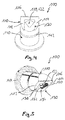
- Fig. 2 shows a nozzle according to the invention 100, by means of which preferably a first bitumen-containing mass or a second bitumen-containing and titanium dioxide-containing mass, but also other materials are austragbar.
- This nozzle 100 may advantageously be part of a discharge device (not shown), for example a caulking gun or a hand extruder.
- the nozzle 100 has a flange 144 and, opposite thereto, a nozzle head 110, which is approximately triangular in cross-section (see FIG Fig. 3 ), on.
- the nozzle head 110 has in its tip a smoothing edge 116 and a nozzle opening 120 with an opening edge 123, wherein through the nozzle opening 120, an opening area 122 (see Fig. 3 ) is defined.
- the nozzle head 110 has on one of its triangular surfaces a discharge part 130, which comprises the nozzle opening 120 except for the formation of a discharge opening 132.
- the discharge part 130 is formed in parts solid with the nozzle head 110. However, it may also be provided a non-massive training.
- contact surfaces 112 and 114 are formed in the triangular surface of the nozzle head 110, the attachment to a surface, for example, left and right of a joint, or a reason of expansion, as already described in the general description, adjacent one hand to a surface, for example, a traffic area, on the other hand to the joint, serve.
- Fig. 3 is a sectional view of the nozzle 100 according to Fig. 2 , from which particularly well the configuration of the nozzle opening 120 with the opening surface 122 and the discharge opening 132 with the discharge opening face 133 can be seen, which is spaced apart outwardly in relation to the opening surface 122 of the nozzle opening 120.
- the discharge part 130 is projectingly arranged on the triangular surface of the nozzle head 110.
- a circumferential groove 142 can be seen on a nozzle body 140, which is a locking or fixing of the nozzle 100, for example on a twin-screw extruder in the context of filling a discharge device which carries the nozzle 100 serves.
- Fig. 4 shows in a perspective view of the nozzle 100 according to Fig. 2 , as well as the Fig. 5 , in particular from Fig. 5 the projecting formation of the discharge part 130 is clearly visible.
- the discharge part 130 has an outer wall 134 and, subsequent thereto, a side wall 136 on each of three sides.
- the side walls 136 are formed with a return to the opening edge 122 of the nozzle opening 120.
- the discharge opening 132 itself is approximately triangular in shape with an open base edge or area on the opening edge 123 of the nozzle opening 120.
- the contact surfaces 112 and 114 serve, for example, a support on a surface 60 according to Fig. 1 or an overlay on the basis of a widening 38 according to Fig. 1 , In the latter case, then the width of the discharge part 130 in approximately the width of the joint 30 according to Fig. 1 correspond and dipping the discharge part 130 in this gap 30 when using the nozzle 100. Then, the joint 30 according to Fig. 1 be filled with at least one layer of a first mass 10. Subsequently, a nozzle 100 can be used with a discharge part 130 having a larger width, wherein then contact surfaces 112 and 114 with the surface 60 according to FIG Fig.
- the second mass 50 can be introduced into the expansion 38, wherein the discharge part 130 then dips into the expansion 38. If, for example, the first mass 10 is introduced into a joint 30 with a widening 38 with a nozzle 100, the second mass 50 can subsequently be introduced in strip form in the region of the widening 38 due to the smooth and closed filling of the joint 30. As far as a joint 30 no widening 38 according to Fig. 1 can, for example, a first mass 10 in at least one layer in the joint 30 according to Fig.
- a joint seal 70 can be generated (s. Fig. 1 ).
- An exemplary bitumen-containing first composition was prepared from 53 wt .-% of a bitumen with a needle penetration at 25 ° C according to DIN EN 1426 from about 160 / 0.1 mm to about 220 / 0.1 mm, 7 wt .-% of a styrene Isoprene-styrene / styrene-isoprene (block) copolymer, 6% by weight of a gum powder made from a recycled rubber product, in particular car tires having a grain size in a range of> 0 to about 0.5 mm, 1, 5% by weight of a montan wax having a solidification point ranging from about 130 ° C to about 150 ° C, 1% by weight of a grafted etylene-maleic anhydride copolymer in the form of pastilles, 12% by weight of a naphthenic process oil Plasticizer, 2% by weight of one fibrous modifier in the form of cellulosic fiber
- a titanium dioxide-containing and bituminous second mass was prepared from 40 wt .-% of a bitumen with a needle penetration at 25 ° C according to DIN EN 1426 from about 160 / 0.1 mm to about 220 / 0.1 mm, 5 wt .-% of a Styrene-isoprene-styrene / styrene-isoprene (block) copolymers, 4 wt .-% of a rubber powder, prepared from a recyclate of rubber products, in particular car tires with a grain size in a range of> 0 to about 0.5 mm, 1 wt % of a montan wax having a freezing point in a range from about 130 ° C to about 150 ° C, 0.7% by weight of a grafted etylene-maleic anhydride copolymer in the form of pastilles, 9% by weight of a naphthenic process oil as a plasticizer, 1.3% by weight of
- the first and second masses prepared as described above had a dynamic viscosity, measured in accordance with DIN EN 13702, at a temperature of 100 ° C., at a pore rate of 20 sec -1 of 75 Pa.s (first mass) or 110 Pa.s ( second mass), at a temperature of 110 ° C. of 45 Pa.s (first mass) or 67 Pa.s (second mass), at a temperature of 120 ° C. of 27 Pa.s (first mass) and 48 Pa, respectively.
- the first and second masses As described above, all the substances mentioned were mixed and stirred together at about 190 ° C. for 3 hours. Subsequently, they were molded to form bars or, particularly at the second mass, tapes and allowed to cool.
- the first and second mass in bar form can then be supplied in particular to a twin-screw extruder, so that on-site processing can be carried out as described in the general description.
- the twin-screw extruder via the twin-screw extruder, the first or second mass in a caulking gun or hand extruder, preferably with a nozzle as in Fig. 2 to 5 described, discharged and then the gap on the cartridge gun or the hand extruder, in particular a vertical joint in a concrete protective wall, are filled.
- a flat nozzle preferably according to the Fig. 2 to 5 , more preferably with a larger opening diameter to achieve coverage of the at least one layer of the first mass disposed therebelow, preferably in that the joint has a widening to the adjacent surface into which the second mass can then be introduced.
- an underfill can be inserted into it and the joint flanks can be provided with an adhesion promoter, as described above in the general description.
- a joint seal is provided which, in particular for vertical joints in concrete protective walls, has the highest possible service life, since corrosion and other types of leaks in concrete protective walls are well prevented.
Landscapes
- Engineering & Computer Science (AREA)
- Chemical & Material Sciences (AREA)
- Structural Engineering (AREA)
- Civil Engineering (AREA)
- Ceramic Engineering (AREA)
- Architecture (AREA)
- Materials Engineering (AREA)
- Organic Chemistry (AREA)
- Health & Medical Sciences (AREA)
- Chemical Kinetics & Catalysis (AREA)
- Medicinal Chemistry (AREA)
- Polymers & Plastics (AREA)
- Mining & Mineral Resources (AREA)
- Compositions Of Macromolecular Compounds (AREA)
- Road Paving Structures (AREA)
- Sealing Material Composition (AREA)
Abstract
Description
- Die vorliegende Erfindung betrifft eine Fugenabdichtung für eine Fuge mit mindestens einer Schicht mindestens einer ersten bitumenhaltigen Masse und einer zweiten bitumenhaltigen und titandioxidhaltigen Masse für eine Fugenabdichtung, die Verwendung einer solchen titandioxidhaltigen Masse als auch eine Fuge mit einer erfindungsgemäßen Fugenabdichtung und/oder titandioxidhaltigen Masse.
- Bitumenhaltige Massen als Fugenmaterial oder zur Verfüllung von Rissen werden insbesondere im Straßenbau und verwandten Bereichen eingesetzt, beispielsweise auch bei der Erstellung, Reparatur oder Sanierung von Verkehrswegen. Bitumen ist ein relativ günstiges Produkt der Erdöldestillation, das aufgrund seiner elastisch-plastischen Eigenschaften nicht nur als Bindemittel in Asphalt, sondern insbesondere auch in einer elastomer-modifizierten, d. h. polymer-modifizierten Form als Fugenmaterial oder Rissfüllmaterial eingesetzt wird.
- Fugenmassen auf Bitumenbasis werden insbesondere als Heißvergussmassen, aber auch als Kaltvergussmassen, oder in Form von Bitumenfugenbändern zum Ausfüllen von horizontal angeordneten Fugen und/oder Rissen eingesetzt. Diese sind insbesondere in den "Zusätzlichen technischen Vertragsbedingungen und Richtlinien für Fugen in Verkehrsflächen, Ausgabe 2001 (ZTV Fug-StB 01)" angesprochen.
- Typischerweise werden horizontale Fugen oder Risse mit Bitumenheißvergussmassen oder Bitumenfugenbändern verfüllt beziehungsweise geschlossen. Vertikale Fugen werden demgegenüber insbesondere mit Massen beziehungsweise Bändern verfüllt, die ihre Grundlage auf Polysulfiden und/oder Polyurethanen haben. Dies hat seinen Grund darin, dass Bitumenmassen, insbesondere Heißvergussmassen, zu niedrigviskos sind, als dass sie in vertikalen Fugen und/oder Rissen eingesetzt werden können, da diese schlicht aus diesen ablaufen. Bitumenfugenbänder hingegen sind in vertikalen Fugen und/oder Rissen nur schwer einsetzbar aufgrund der oftmals spezifischen Geometrie derselben, oder aber weil diese ebenfalls beim Einsetzen, selbst unter Verwendung von Primern beziehungsweise Haftvermittlern, nicht ohne Weiteres nach Einlegung in eine vertikale Fuge in selbiger verbleiben, sondern aus dieser selbständig aufgrund des eigenen Gewichtes sich herauslösen.
- Insbesondere vertikale Fugen finden sich im Bereich von Betonschutzwänden an Verkehrswegen. Betonschutzwände werden in aller Regel aus Formsteinen hergestellt und beispielweise zum Lärmschutz, oder aber auch für Unterteilungen von Fahrbahnen, beispielsweise auf Autobahnen oder Bundesstraßen, eingesetzt. Bei der Erstellung derartiger Schutzwände aus Beton werden zunächst Betonschutzwände kontinuierlich hergestellt und anschließend Fugen eingebracht, um einen Bewegungsausgleich zu schaffen und damit mögliche Spannungen abzubauen. In einer alternativen Bauweise werden die entsprechenden Formsteine nebeneinander aufgestellt, wobei sich zwischen gegenüberliegenden Stirnflächen eine Fuge bildet. Die genannten Fugen gilt es zu verschließen. Fugenabdichtungen für vertikale Fugen in insbesondere Betonschutzwänden erfolgen beispielsweise durch Einlage geeigneter Fugenbänder, gegebenenfalls auch mit Profil, wobei jedoch die vorstehend geschilderten Probleme auftreten. Auch können beispielsweise Massen aus Polysulfiden oder Polyurethanen verwendet werden, um die Fugen zu schließen, welche jedoch im Vergleich zu bituminösen Materialien relativ kostenintensiv sind.
- Es ist daher Aufgabe der vorliegenden Erfindung, eine Fugenabdichtung zur Verfügung zu stellen, welche die vorstehend geschilderten aus dem Stand der Technik bekannten Probleme löst, insbesondere einen langanhaltenden Schutz vor Korrosionen gleich welcher Art zu bieten.
- Diese Aufgabe wird erfindungsgemäß gelöst durch eine Fugenabdichtung für eine Fuge, insbesondere in Betonteilen, insbesondere in Betonschutzwänden, mit mindestens einer Schicht einer bitumenhaltigen ersten Masse und mindestens einer Schicht einer bitumenhaltigen zweiten Masse, wobei die mindestens eine Schicht der zweiten Masse auf der mindestens einen Schicht der ersten Masse angeordnet ist und eine freiliegende Oberfläche bildet, wobei ein Verhältnis einer Schichtstärke der ersten Masse und der zweiten Masse in einem Bereich von etwa 250:1 bis etwa 1:1 beträgt und wobei die zweite Masse im Unterschied zur erste Masse etwa 10 Gew.-% bis etwa 40 Gew.-%, bezogen auf die Gesamtmenge der zweiten Masse, Titandioxid umfasst.
- Bevorzugt liegt das Verhältnis der Schichtstärke der ersten Masse und der zweiten Masse in einem Bereich von etwa 50:1 bis etwa 2:1, weiter bevorzugt in einem Bereich von etwa 30:1 bis etwa 2,5:1.
- Bevorzugt wird im Sinne der vorliegenden Erfindung mindestens ein Titandioxid in der titandioxidhaltigen und bitumenhaltigen zweiten Masse eingesetzt, welches eine Anatas-Struktur aufweist. Aber auch mindestens ein Titandioxid mit einer Rutil-Struktur oder Mischungen von Titandioxiden unterschiedlicher Struktur derselben sind einsetzbar. Besonders bevorzugt weist das Titandioxid der zweiten Masse eine Schüttdichte in einem Bereich von etwa 450 kg/m3 bis etwa 750 kg/m3, weiter bevorzugt eine Schüttdichte in einem Bereich von etwa 520 kg/m3 bis etwa 660 kg/m3 auf. Besonders bevorzugt liegt das Titandioxid in der zweiten Masse in Pulverform vor. Vorzugsweise liegt das relative Streuvermögen gemäß DIN 53165 des eingesetzten Titandioxids in einem Bereich von etwa 58 bis etwa 75, bevorzugt in einem Bereich von etwa 60 bis etwa 68. Besonders bevorzugt ist das in der zweiten Masse eingesetzte Titandioxid nicht durch weitere Elemente wie beispielsweise Aluminium, Silicium oder Mangan stabilisiert. Bevorzugt umfasst die titandioxidhaltige und bitumenhaltige zweite Masse etwa 15 Gew.-% bis etwa 35 Gew.-%, weiter bevorzugt etwa 20 Gew.-% bis etwa 30 Gew.-%, jeweils bezogen auf die Gesamtmenge der zweiten Masse mindestens eines Titandioxides.
- Die bitumenhaltige erste Masse ist insbesondere eine solche, welche in der
WO 2014/173513 A1 beschrieben ist. Insoweit wird die Offenbarung derselben vollständig zum Gegenstand der vorliegenden Erfindung gemacht. Demnach umfasst die bitumenhaltige erste Masse - mindestens ein Bitumen in einer Menge in einem Bereich von etwa 30 Gew.-% bis etwa 75 Gew.-%;
- mindestens ein Elastomer, ausgewählt aus einer Gruppe umfassend Styrol-Butadien-Copolymere, Styrol-Butadien-Stryrol-(Block-)Copolymere, Styrol-Isopren-Styrol-(Block-)Copolymere, Styrol-Isopren-(Block-)Copolymere, synthetische und/oder natürliche Kautschuke, in einer Menge in einem Bereich von etwa 2,5 Gew.-% bis etwa 22 Gew.-%;
- mindestens einen pulverförmigen mineralischen Füllstoff in einer Menge in einem Bereich von etwa 12 Gew.-% bis etwa 35 Gew.-%;
- mindestens ein faserförmiges Stellmittel zur Einstellung der Festigkeit, ausgewählt aus einer Gruppe umfassend Cellulose, Glasfasern und/oder Kunststofffasern, in einer Menge in einem Bereich von etwa 0,5 Gew.-% bis etwa 5 Gew.-%; und
- mindestens ein Polymer, hergestellt aus einem Olefin und einer α, β-ungesättigten Carbonsäure und/oder einem α, β-ungesättigtem Carbonsäureanhydrid, in einer Menge in einem Bereich von etwa 0,1 Gew.-% bis etwa 8 Gew.-%, bevorzugt bis etwa 5 Gew.-%,
- Die titandioxidhaltige und bitumenhaltige zweite Masse der erfindungsgemäßen Fugenabdichtung ist ebenfalls Gegenstand der vorliegenden Erfindung. Diese umfasst
- mindestens ein Bitumen in einer Menge in einem Bereich von etwa 25 Gew.-% bis etwa 60 Gew.-%;
- mindestens ein Elastomer, ausgewählt aus einer Gruppe umfassend Styrol-Butadien-Copolymere, Styrol-Butadien-Styrol-(Block-)Copolymere, Styrol-Isopren-(Block-)Copolymere und/oder Styrol-Isopren-Styrol-(Block-) Copolymere, synthetische und/oder natürliche Kautschuke, in einer Menge in einem Bereich von etwa 2 Gew.-% bis etwa 10 Gew.-%;
- mindestens einen pulverförmigen mineralischen Füllstoff in einer Menge in einem Bereich von etwa 7 Gew.-% bis etwa 25 Gew.-%;
- mindestens ein faserförmiges Stellmittel zur Einstellung der Festigkeit, ausgewählt aus einer Gruppe umfassend Zellulose, Glasfasern und/oder Kunststofffasern, in einer Menge in einem Bereich von etwa 0,3 Gew.-% bis etwa 5 Gew.-%;
- mindestens ein Polymer, hergestellt aus einem Olefin und einer α, β-ungesättigten Carbonsäure und/oder einem α, β-ungesättigtem Carbonsäureanhydrid, in einer Menge in einem Bereich von etwa 0,1 Gew.-% bis etwa 6 Gew.-%; und
- mindestens ein Titandioxid in einer Menge in einem Bereich von etwa 10 Gew.-% bis etwa 40 Gew.-%,
- Soweit in der vorliegenden Anmeldung der Begriff "etwa" in Hinblick auf Werte, Wertebereiche, insbesondere Gewichtsprozentbereiche, Verhältnisse oder Bereiche der Faserlängen oder Faserdicken, verwendet wird, ist hierunter zu verstehen, dass geringfügige Abweichungen von den angegebenen Bereichen aus dem Schutzbereich, der durch die Angaben in den Patentansprüchen vermittelt wird, nicht hinausführen. Insbesondere sind Abweichungen von +/- 10 Prozent, bevorzugt +/- 5 Prozent, bezogen auf die jeweilige Angabe, von dem Begriff "etwa" abgedeckt. Soweit in der vorliegenden Erfindung Bezug genommen wird auf Normen, sind die in der zum Zeitpunkt der Einreichung der vorliegenden Anmeldung gültigen Fassungen oder letzten Fassungen, so die Normen aufgehoben wurden, gemeint.
- Soweit in der vorliegenden Anmeldung der Begriff "Bitumen" verwendet wird, ist hierunter insbesondere ein Bitumen mit einer Nadelpenetration bei 25 °C in Übereinstimmung mit der DIN EN 1426 (Maßeinheit 0,1 mm) in einem Bereich von etwa 80 bis etwa 300, bevorzugt in einem Bereich von etwa 140 bis etwa 250, noch weiter bevorzugt in einem Bereich von etwa 160 bis etwa 220, zu verstehen. Besonders bevorzugt wird dabei Bitumen eingesetzt, welches für den Straßenbau geeignet ist, in Anlehnung an die DIN 1995-1. Bevorzugt umfasst die bitumenhaltige erste Masse das mindestens eine Bitumen in einer Menge in einem Bereich von etwa 40 Gew.-% bis etwa 65 Gew.-%, weiter bevorzugt in einer Menge von etwa 45 Gew.-% bis etwa 58 Gew.-%, noch weiter bevorzugt in einer Menge in einem Bereich von etwa 42 Gew.-% bis etwa 56 Gew.-%. Bevorzugt umfasst die titandioxidhaltige und bitumenhaltige zweite Masse Bitumen in einer Menge in einem Bereich von etwa 30 Gew.-% bis etwa 55 Gew.-%, weiter bevorzugt in einem Bereich von etwa 33 Gew.-% bis etwa 48 Gew.-%.
- Im Sinne der vorliegenden Erfindung wird unter dem Begriff "Elastomer" ein Polymer mit gummielastischem Verhalten, das bei Raumtemperatur wiederholt mindestens auf das zweifache seiner Länge gedehnt werden kann und nach Aufhebung des für die Dehnung erforderlichen Zwanges sofort wieder annähernd die Ausgangslänge einnimmt, verstanden. Besonders bevorzugt im Sinne der vorliegenden Erfindung wird das mindestens eine Elastomer ausgewält aus einer Gruppe umfassend Styrol-Butadien-Copolymere, Styrol-Butadien-Styrol-(Block-)Copolymere, Styrol-Isopren-(Block-)Copolymere, Styrol-Isopren-Styrol-(Block-)Copolymere, Butadien-Kautschuke, Butyl-Kautschuke, halogenierte Butyl-Kautschuke und/oder natürliche Kautschuke. Das mindestens eine Elastomer kann dabei vorzugsweise in Form eines Mehls, weiter bevorzugt in Form eines Gummimehls, der Mischung zugegeben werden. Vorzugsweise liegt bei Zugabe des mindestens einen Elastomeren in Form eines Mehles die Körnung in einem Bereich von > 0 mm bis etwa 0,5 mm. Bei Einsatz des mindestens einen Elastomeren in Form eines Mehles kann dieses vorteilhafterweise auch eine Mischung unterschiedlicher Elastormere darstellen, und beispielsweise aus einer Mischung umfassend natürliche Kautschuke, Styrol-Butadien-Kautschuke, Styrol-Isopren-Styrol-Copolymere, Styrol-Isopren-Copolymere, Butadien-Kautschuke und/oder Butyl-Kautschuke beziehungsweise halogenierte Kautschuke bestehen. Besonders bevorzugt wird als Elastomer eingesetzt ein Styrol-Isopren-Styrol-Copolymer, insbesondere wenn dieses als Blockcopolymer ausgebildet ist, bevorzugt in Form eines Styrol-Isopren-Styrol/Styrol-Isopren-Blockcopolymers. Weiter vorteilhafterweise wird als Elastomer eingesetzt eine Mischung aus einem Styrol-Butadien-Styrol-Copolymeren, gegebenenfalls auch Blockcopolymeren, und/oder einem Styrol-Isopren-Styrol-Copolymeren oder aber Blockcopolymeren in Mischung mit einem Mehl, welches ein Rezyclat darstellt, vorzugsweise aus Automobilreifen, und dabei eine Mischung eines natürlichen Kautschukes, eines Styrol-Butadien-Kautschukes, eines Butadien-Kautschukes, eines Butyl-Kautschukes und/oder eines halogenierten Butyl-Kautschukes darstellt.
- Besonders bevorzugt wird das mindestens eine Elastomer in einer Menge von etwa 2 Gew.-%, bevorzugt etwa 5 Gew.-%, bis etwa 20 Gew.-%, weiter bevorzugt in einer Menge von etwa 8 Gew.-% bis etwa 16 Gew.-%, noch weiter bevorzugt in einer Menge von etwa 11 Gew.-% bis etwa 15 Gew.-%, in der bitumenhaltigen ersten Masse eingesetzt, wobei die Gewichtsprozente jeweils bezogen sind auf die Gesamtmenge der ersten Masse. Besonders bevorzugt wird das mindestens eine Elastomer in der titandioxidhaltigen und bitumenhaltigenzweiten Masse in einer Menge in einem Bereich von etwa 3 Gew.-% bis etwa 9 Gew.-%, weiter bevorzugt in einer Menge in einem Bereich von etwa 4 Gew.-% bis etwa 7,5 Gew.-% eingesetzt, wobei die Gewichtsprozente jeweils bezogen sind auf die Gesamtmenge der zweiten Masse. Besonders bevorzugt weist die erfindungsgemäße Masse das mindestens eine Elastomer, insbesondere ausgebildet als Styrol-Isopren-Styrol-(Block-)Copolymer und/oder Styrol-Butadien-Styrol-(Block-)Copolymer, beide insbesondere in Form von Block-copolymeren, in einer Menge in einem Bereich von etwa 2,5 Gew.-% bis etwa 10 Gew.-%, weiter bevorzugt in einer Menge von etwa 5 Gew.-% bis etwa 9 Gew.-%, als auch ein weiteres Elastomer auf der Basis eines Mehls, gewonnen als Rezyclat, bevorzugt aus Automobilreifen, umfassend eine Mischung verschiedener Elastomere wie vorstehend erwähnt, in einer Menge von etwa 3 Gew.-% bis etwa 12 Gew.-%, weiter bevorzugt eine Menge von etwa 5 Gew.-% bis etwa 8 Gew.-%, auf.
- Der mindestens eine pulverförmige mineralische Füllstoff im Sinne der vorliegenden Erfindung ist vorzugsweise ausgewählt aus einer Gruppe umfassend Silikate, Phosphate und/oder Sulfate. Weiter bevorzugt ist der pulverförmige mineralische Füllstoff karbonatfrei. Besonders bevorzugt im Sinne der vorliegenden Erfindung ist der mindestens eine pulverförmige mineralische Füllstoff ausgewählt aus einer Gruppe umfassend Magnesiumsilikate, insbesondere ein Talkum. Der mindestens eine pulverförmige mineralische Füllstoff kann dabei auch in einer Mischung mit beispielsweise einem Chlorit eingesetzt werden. Besonders bevorzugt ist der mindestens eine pulverförmige mineralische Füllstoff in einer Menge in einem Bereich von etwa 14 Gew.-% bis etwa 30 Gew.-%, weiter bevorzugt in einer Menge in einem Bereich von etwa 15 Gew.-% bis etwa 23 Gew.-%, jeweils bezogen auf die Gesamtmenge der ersten Masse, eingesetzt. Bevorzugt ist der mindestens eine pulverförmige mineralische Füllstoff in der titandioxidhaltigen und bitumenhaltigen zweiten Masse in einer Menge in einem Bereich von etwa 9 Gew.-% bis etwa 22 Gew.-%, weiter bevorzugt in einer Menge in einem Bereich von etwa 10 Gew.-% bis etwa 18 Gew.-%, jeweils bezogen auf die Gesamtmenge der zweiten Masse, eingesetzt.
- Weiter bevorzugt umfassen die erste und die erfindungsgemäße zweite Masse mindestens ein faserförmiges Stellmittel, welches zur Einstellung der Festigkeit, insbesondere der Standfestigkeit, dient. Mittels dieses faserförmigen Stellmittels kann insbesondere auch die Verarbeitungskonsistenz der ersten und zweiten Masse eingestellt werden. Dabei ist das mindestens eine faserförmige Stellmittel vorteilhafterweise in einer Menge in einem Bereich von etwa 1 Gew.-% bis etwa 4,5 Gew.-%, weiter bevorzugt in einer Menge in einem Bereich von etwa 1,6 Gew.-% bis etwa 3 Gew.-%, jeweils bezogen auf die Gesamtmenge der ersten Masse, in dieser enthalten. Das mindestens eine faserförmige Stellmittel ist in der titandioxidhaltigen und bitumenhaltigen zweiten Masse vorteilhafterweise in einer Menge in einem Bereich von etwa 0,75 Gew.-% bis etwa 2,5 Gew.%, weiter bevorzugt in einer Menge in einem Bereich von etwa 1 Gew.-% bis etwa 2 Gew.-%, jeweils bezogen auf die Gesamtmenge der zweiten Masse, eingesetzt. Vorteilhafterweise ist das mindestens eine faserförmige Stellmittel ausgewählt aus einer Gruppe umfassend Cellulose, Glasfasern und/oder Kunststofffasern, und ist besonders bevorzugt aus einer Gruppe umfassend Cellulose-Fasern. Das mindestens eine Stellmittel weist dabei vorzugsweise eine durchschnittliche Faserlänge in einem Bereich von etwa 500 µm bis etwa 1500 µm auf, weiter bevorzugt eine Faserlänge in einem Bereich von etwa 800 µm bis etwa 1500 µm. Weiter bevorzugt weist das mindestens eine faserförmige Stellmittel eine durchschnittliche Faserdicke in einem Bereich von etwa 20 µm bis etwa 80 µm auf, weiter bevorzugt eine solche in einem Bereich von etwa 30 µm bis etwa 60 µm.
- Im Sinne der vorliegenden Erfindung umfasst die erste und zweite Masse weiterhin mindestens ein Polymer, welches sich von dem weiter vorstehend beschriebenen mindestens einem Elastomeren unterscheidet, und hergestellt ist aus einem Olefin und insbesondere einer α, β-ungesättigten Carbonsäure und/oder insbesondere α, β-ungesättigtem Carbonsäureanhydrid. Dieses ist vorteilhafterweise in einer Menge in einem Bereich von etwa 0,5 Gew.-% bis etwa 2,8 Gew.-%, weiter bevorzugt etwa 0,8 Gew.-% bis etwa 2 Gew.-%, noch weiter bevorzugt in einer Menge in einem Bereich von etwa 0,9 Gew.-% bis etwa 1,4 Gew.-%, in der ersten Masse enthalten, wobei die Gewichtsprozente jeweils bezogen sind auf die Gesamtmenge der ersten Masse. In der erfindungsgemäßen titandioxidhaltigen und bitumenhaltigen zweiten Masse ist das mindestens eine Polymer in einer Menge in einem Bereich von etwa 0,25 Gew.-% bis etwa 3 Gew.-%, weiter bevorzugt in einer Menge von etwa 0,45 Gew.-% bis etwa 1,2 Gew.-%, noch weiter bevorzugt in einer Menge in einem Bereich von etwa 0,5 Gew.-% bis etwa 1 Gew.-%, wobei die Gewichtsprozente jeweils bezogen sind auf die Gesamtmenge der zweiten Masse, enthalten.Besonders bevorzugt ist das Polymer hergestellt aus einem Olefin, ausgewählt aus einer Gruppe umfassend Ethylen und/oder Propylen oder Vinylalkohol, und Maleinsäureanhydrid. Statt Maleinsäureanhydrid wäre auch zum Beispiel Acrylsäure möglich einzusetzen. Auch können lonomere der genannten Polymere eingesetzt werden. Besonders bevorzugt werden als Polymere des Maleinsäureanhydrides Copolymere oder gepfropfte Polymere des Maleinsäureanhydrides mit Propylen und/oder Ethylen eingesetzt. Möglich ist der Einsatz von statistischen Copolymeren mit einem Anteil an Maleinsäureanhydrid von < 50 Mol-% als auch alternierende Copolymere mit einem Maleinsäureanhydrid-Anteil von 50 Mol-%. Dabei können eine Vielzahl von Monomeren unterschiedlicher Struktur eingesetzt werden. Bevorzugt wird das mindestens eine Polymer eingesetzt in Form von Pastillen, mit einem mittleren Durchmesser in einem Bereich von etwa 7 mm bis etwa 10 mm. Die Dichte des eingesetzten Polymeren, bevorzugt die Dichte des eingesetzten Maleinsäureanhydridcopolymeren, liegt in einem Bereich von etwa 0,90 g/cm3 bis etwa 0,935 g/cm3, gemessen gemäß ISO 1183. Besonders bevorzugt im Sinne der vorliegenden Erfindung wird als Polymer ein Ethylen-Maleinsäureanhydrid-Copolymer in den vorstehend genannten Gewichtsprozentbereichen, vorzugsweise als statistisches, aber auch als alternierendes Copolymer, eingesetzt, besonders bevorzugt ein gepfropftes. Das eingesetzte Polymer aus Ethylen und/oder Propylen und Maleinsäureanhydrid oder Acrylsäure weist vorzugsweise eine Viskosität nach Brookfield bei einer Temperatur von 140°C in einem Bereich von etwa 400 bis etwa 3000 mPa*s, weiter bevorzugt in einem Bereich von etwa 500 mPa*s bis etwa 2000 mPa*s, auf. Bevorzugt weist das aus Ethylen und/oder Propylen und Maleinsäureanhydrid oder Acrylsäure hergestellte Polymer einen Tropfpunkt gemäß ASTM D3954 in einem Bereich von etwa 85°C bis etwa 125°C, weiter bevorzugt in einem Bereich von etwa 90°C bis etwa 115°C auf, gemessen beispielsweise mit einem Tropfpunktanalysesystem DP70 der Mettler-Toledo AG, Schwerzenbach, Schweiz. Das mindestens eine Polymere dient vorteilhafterweise als Kompatibilisator, um insbesondere die Einbindung des mindestens einen faserförmigen Stellmittels, aber auch des pulverförmigen mineralischen Füllstoffes in der erfindungsgemäßen Masse zu ermöglichen. Darüber hinaus wird durch das mindestens eine Polymer auch der Erweichungspunkt der ersten und zweiten Masse erhöht, beziehungsweise die Schmelzviskosität desselben verringert. Bezüglich der beiden zuletzt genannten Eigenschaften ähnelt damit das eingesetzte Polymer einem vorteilhafterweise in der ersten und zweiten Masse eingesetzten Wachs, wozu weiter unten Ausführungen getroffen werden.
- Weiter bevorzugt kann die erste Masse mindestens ein Wachs umfassen in einer Menge in einem Bereich von etwa 0,5 Gew.-% bis etwa 3 Gew.-%, weiter bevorzugt in einer Menge in einem Bereich von etwa 1 Gew.-% bis etwa 2 Gew.-%, jeweils bezogen auf die Gesamtmenge der ersten Masse. Die erfindungsgemäße zweite Masse umfasst bevorzugt mindestens ein Wachs in einer Menge in einem Bereich von etwa 0,5 Gew.-% bis etwa 2,5 Gew.-%, weiter bevorzugt in einer Menge in einem Bereich von etwa 0,8 Gew.-% bis etwa 1,5 Gew.-%, jeweils bezogen auf die Gesamtmenge der zweiten Masse.
- Besonders bevorzugt wird das Wachs ausgewählt aus einer Gruppe umfassend Fischer-Tropsch-Wachse und/oder Montanwachse. Das mindestens eine Wachs wird vorteilhafterweise eingesetzt zur Erhöhung des Erweichungspunktes der ersten, ggf. der zweiten Masse beziehungsweise der Verringerung der Schmelzviskosität derselben.
- Die erste Masse umfasst weiterhin vorteilhafterweise mindestens einen Weichmacher, ausgewählt aus der Gruppe der aliphatischen und/oder naphthenischen Öle, in einer Menge in einem Bereich von etwa 5 Gew.-% bis etwa 20 Gew.-%, weiter bevorzugt in einer Menge in einem Bereich von etwa 8 Gew.-% bis etwa 15 Gew.-%, jeweils bezogen auf die Gesamtmenge der ersten Masse. Die erfindungsgemäße titandioxidhaltige und bitumenhaltige zweite Masse umfasst vorteilhafterweise mindestens einen Weichmacher, ausgewählt aus einer Gruppe der aliphatischen und/oder naphthenischen Öle, insbesondere einen solchen identisch zu demjenigen, der von der ersten Masse umfasst sein kann, in einer Menge in einem Bereich von etwa 3,5 Gew.-% bis etwa 15 Gew.-%, weiter bevorzugt in einem Bereich von etwa 5 Gew.-% bis etwa 12 Gew.-%, jeweils bezogen auf die Gesamtmenge der zweiten Masse. Besonders bevorzugt umfasst die erste und/oder zweite Masse mindestens ein naphthenisches Prozessöl als Weichmacher. Der mindestens eine Weichmacher weist vorteilhafterweise eine Dichte bei 25°C gemäß ISO 12185 in einem Bereich von etwa 0,89 kg/dm3 bis etwa 0,915 kg/dm3 auf. Er weist vorteilhafterweise eine Viskosität bei 40 °C gemäß ISO 3104 in einem Bereich von etwa 50 mm2/s (cSt), bevorzugt etwa 130 mm2/s(cSt), bis etwa 170 mm2/s (cSt), bevorzugt bis etwa 155 mm2/s (cSt), auf.
- Die erste und/oder zweite Masse weist vorteilhafterweise einen Erweichungspunkt gemäß DIN EN 1427 von größer gleich etwa 85 °C, weiter bevorzugt größer gleich etwa 90 °C, auf. Weiter bevorzugt weist die erste und/oder zweite Masse eine Konus-Penetration gemäß DIN EN 13880-2 bei 25 °C in einem Bereich von etwa 40 bis etwa 130 1/10 mm, weiter bevorzugt in einem Bereich von etwa 50 bis etwa 110 1/10 mm, auf. Weiter bevorzugt weist die erste und/oder zweite Masse ein elastisches Rückstellvermögen gemäß DIN EN 12880-3 von kleiner gleich etwa 60 %, weiter bevorzugt kleiner gleich etwa 50 %, auf.
- Die erste und/oder zweite Masse weisen den großen Vorteil auf, dass diese aufgrund ihrer hohen Standfestigkeit auch bei Temperaturen von etwa 70 °C oder mehr eingesetzt werden können, und zwar insbesondere im Bereich vertikaler Fugen und Risse. Durch ihre spezifischen Eigenschaften können die ersten und/oder zweiten Massen in horizontalen als auch in vertikalen Flächen und dabei auch bei Anschlüssen von horizontalen Fugen beziehungsweise Rissen an vertikale Fugen beziehungsweise Risse eingesetzt werden, so dass Unverträglichkeitsprobleme sich nicht stellen. Die erste und die zweite Masse können auch vorteilhafterweise insbesondere bei Betonbauteilen, insbesondere Betonschutzwänden, oder Fahrbahndecken, die aggressiven Medien ausgesetzt sind, sowohl für horizontale als auch vertikale Verwendungen eingesetzt werden. Die erste und zweite Masse können in überfahrenen Fugen in Asphalt- und Betonflächen eingesetzt werden, das heißt Fugen, aber auch Risse, die durch Nutzfahrzeuge wie Traktoren, Lkws oder Pkws überfahren werden. Die erste und zweite Masse sind beständig gegenüber aggressiven Medien auch über lange Zeiträume. Sie sind einkomponentig und damit einfach zu verarbeiten. Sie werden bevorzugt erwärmt beziehungsweise heiß verarbeitet bei Temperaturen in einem Bereich von etwa 90°C bis etwa 200°C, bevorzugt in einem Bereich von etwa 100°C bis etwa 160°C. Die erste und die zweite Masse sind sehr gut verträglich miteinander. Bevorzugt sind die erste und die zweite Masse bis auf das Titandioxid aus identischen Bestandteilen zusammengesetzt. Weiter bevorzugt ist zumindest das mindestens eine eingesetzte Bitumen und das mindestens eine eingesetzte Polymer, weiter bevorzugt zusätzlich auch das mindestens eine eingesetzte Elastomer, in der ersten und der zweiten Masse identisch. Identisch bedeutet dabei, dass die Bestandteile eine chemisch identische Struktur, weiter bevorzugt auch physikalischidentische Eigenschaften, aufweisen. In der erfindungsgemäßen Fugenabdichtung verwachsen die erste und die zweite Masse bevorzugt miteinander. Eine Ablösung einer Schicht der zweiten Masse von einer unter dieser angeordneten Schicht der ersten Masse ist vorteilhafterweise verhindert. Bereits bei Raumtemperatur, erst recht bei erhöhten Temperaturen ab etwa 40°C, bevorzugt ab etwa 50°C, findet eine Verwachsung statt. Die erfindungsgemäße Fugenabdichtung schützt vorteilhafterweise eine innere Bewehrung von Betonteilen, insbesondere Betonschutzwänden, insbesondere vor Korrosion.
- Bevorzugt deckt die mindestens eine Schicht der zweiten Masse die mindestens eine Schicht der ersten Masse vollständig ab. Die Schicht der zweiten Masse weist bevorzugt eine größere Breite auf als die Schicht der ersten Masse, deren Breite durch eine Breite der Fuge vorgegeben ist. Die Bedeckung durch die zweite Masse kann insbesondere derart erfolgen, dass die mindestens eine Schicht der zweiten Masse oberhalb der Fuge, d. h, oberhalb eines oberen Fugenrandes derselben, angeordnet ist, und damit eine an dem oberen Fugenrand angrenzende Oberfläche, z. B. eines Betonteils, insbesondere einer Betonschutzwand, überdeckt, z. B. etwa 1 mm bis etwa 5 mm, inbesondere beidseitig der Fuge. Alternativ, aber auch kumulativ kann die mindestens eine Schicht der zweiten Masse in einer Aufweitung der Fuge an deren oberem Fugenrand aufgenommen sein.
- Die zweite Masse kann als Band oder als formlose Masse ausgebildet sein. Als Band kann sie z. B. über einer in einer Fuge eingebrachten mindestens einen Schicht der ersten Masse angeordnet werden, wobei eine Verwachsung der Schichten, bevorzugt bei erhöhten Temperaturen, erfolgt, wobei eine Restwärme der ersten Masse oder eine Temperatur von z. B. 23°C ausreichend ist.
- Darüber hinaus ermöglichen die ersten und zweiten Massen auch eine gute Verbindung bei Anschlüssen zu anderen Bitumenfugenmassen, da eine Diffusion in diese und aus diesen in die ersten und zweiten Massen auch nach Abkühlung ermöglicht ist. Auch können Fugen und Risse einfach Instand gesetzt werden, insbesondere Wartungsfugen, da sich die ersten und zweiten Massen gut an älteres Bitumenfugenmaterial anbauen lassen und sich beispielsweise mit einem heißen Messer oder Spachtel einfach nacharbeiten lassen.
- Weiterhin kann die erste und zweite Masse auch sonstige übliche Additive umfassen. Insbesondere kann die erste und/oder zweite Masse umfassen Antioxidationsmittel, thermische Stabilisationsmittel und sonstige Stabilisatoren. Soweit Antioxidationsmittel vorgesehen werden, sind diese in der ersten und/oder zweiten Masse zugegen in einer Menge in einem Bereich von etwa 0,05 Gew.-% bis etwa 0,8 Gew.-%, bevorzugt in einer Menge in einem Bereich von etwa 0,1 Gew.-% bis etwa 0,45 Gew.-%, wobei die Gew.-% jeweils bezogen sind auf die Gesamtmenge der ersten beziehungsweise zweiten Masse. Soweit in der ersten und/oder zweiten Masse thermische Stabilisationsmittel und sonstige Stabilisatoren zugegen sind, sind diese von der ersten oder zweiten Masse umfasst in einer Menge in einem Bereich von etwa 0,1 Gew.-% bis etwa 1 Gew.-%, weiter bevorzugt in einer Menge in einem Bereich von etwa 0,15 Gew.-% bis etwa 0,6 Gew.-%, wobei die Gew.-% jeweils bezogen sind auf die Gesamtmenge der ersten oder zweiten Masse.
- Besonders bevorzugt umfasst die erste Masse etwa 46 Gew.-% bis etwa 60 Gew.-% mindestens eines Bitumens, insbesondere eines Bitumens mit einer Nadelpenetration in einem Bereich von etwa 160 bis etwa 220, als Elastomer mindestens ein Styrol-Isopren-Styrolblockcopolymer in einer Menge in einem Bereich von etwa 5 Gew.-% bis etwa 10 Gew.-%, Gummimehl, insbesondere als Rezyklat, in einer Menge in einem Bereich von etwa 4 Gew.-% bis etwa 10 Gew.-%, mindestens ein Wachs, insbesondere ein Montanwachs, in einer Menge in einem Bereich von etwa 1 Gew.-% bis etwa 2 Gew.-%, als faserförmiges Stellmittel Cellulose, insbesondere Cellulose mit einer durchschnittlichen Faserlänge in einem Bereich von etwa 600 µm bis etwa 1500 um, in einer Menge in einem Bereich von etwa 1 Gew.-% bis etwa 4 Gew.-%, mindestens ein gepropftes Polymer, hergestellt aus Ethylen und/oder Propylen und Maleinsäureanhydrid, in einer Menge in einem Bereich von etwa 0,5 Gew.-% bis etwa 5 Gew.-% und einem Tropfpunkt in einem Bereich von etwa 100°C bis etwa 120°C, gemessen gemäß ASTM D3954, mindestens ein Prozessöl als Weichmacher in einer Menge in einem Bereich von etwa 5 Gew.-% bis etwa 16 Gew.-%, als mineralischen, pulverförmigen Füllstoff Talkum in einer Menge in einem Bereich von etwa 13 Gew.-% bis etwa 22 Gew.-%, sowie gegebenenfalls weitere Additive wie Antioxidantien, thermische Stabilisatoren und sonstige Stabilisationsmittel in einer Menge insgesamt in einem Bereich von 0,2 Gew.-% bis etwa 1 Gew.-%, wobei die vorgenannten Gew.-%-Angaben jeweils bezogen sind auf die Gesamtmenge der ersten Masse.
- Besonders bevorzugt umfasst die erfindungsgemäße titandioxidhaltige und bitumenhaltige zweite Masse etwa 35 Gew.-% bis etwa 44,5 Gew.-% mindestens eines Bitumens, insbesondere eines Bitumens mit einer Nadelpenetration in einem Bereich von etwa 160 bis etwa 220, als Elastomer mindestens ein Styrol-Isopren-Styrol-(Block-) Copolymer in einer Menge in einem Bereich von etwa 3,5 Gew.-% bis etwa 7 Gew.-%, Gummimehl, insbesondere als Recyclat, in einer Menge in einem Bereich von etwa 3 Gew.-% bis etwa 6 Gew.-%, mindestens ein Wachs, insbesondere ein Montanwachs, in einer Menge von etwa 0,5 Gew.-% bis etwa 1,5 Gew.-%, als faserförmiges Stellmittel Cellulose, insbesondere Cellulose mit einer durchschnittlichen Faserlänge in einem Bereich von etwa 600 µm bis etwa 1.500 µm, in einer Menge in einem Bereich von etwa 1 Gew.-% bis etwa 2 Gew.-%, mindestens ein gepfropftes Polymer, hergestellt aus Ethylen und/oder Propylen und Maleinsäureanhydrid, in einer Menge in einem Bereich von etwa 0,5 Gew.-% bis etwa 1 Gew.-% und mit einem Tropfpunkt in einem Bereich von etwa 100°C bis etwa 120°C, gemessen gemäß ASTM D3954, mindestens ein Prozessöl als Weichmacher in einer Menge in einem Bereich von etwa 6 Gew.-% bis etwa 13 Gew.-%, als mineralischen, pulverförmigen Füllstoff Talkum in einer Menge in einem Bereich von etwa 10 Gew.-% etwa 16 Gew.-%, mindestens ein Titandioxid mit Anatas-Struktur in Pulverform mit einer Schüttdichte in einem Bereich von etwa 500 kg/m3 bis etwa 650 kg/m3 in einer Menge in einem Bereich von etwa 21 Gew.-% bis etwa 29 Gew.-%, sowie gegebenenfalls weitere Additive wie Antioxidantien, thermische Stabilisatoren und sonstige Stabilisationsmittel in einer Menge insgesamt in einem Bereich von etwa 0,35 Gew.-% bis etwa 0,7 Gew.-%, wobei sämtliche der vorgenannten Gewichtsprozentangaben jeweils bezogen sind auf die Gesamtmenge der zweiten erfindungsgemäßen Masse.
- Die zweite Masse kann z. B. in Bandform vorliegen. Sie kann dann als Fugenabdeckband eingesetzt werden oberhalb mindestens einer Schicht der mindestens einen ersten Masse. Die Breite des Bandes ist vorzugsweise größer als eine Breite der Fuge und damit einer Breite der mindestens einen Schicht der ersten Masse. Die zweite Masse kann zu Verarbeitungszwecken aber auch in Riegelform hergestellt und dann plastifiziert und erwärmt werden, z. B. durch eine Extrusionsvorrichtung, um anschließend in eine Fuge als formlose Masse eingegeben zu werden. Auf gleiche Weise kann die erste Masse verarbeitet werden.
- Die erfindungsgemäße Fugenabdichtung weist den großen Vorteil auf, dass bei Verwendung derselben insbesondere in vertikalen Fugen einerseits eine kostengünstige Verfüllung derselben möglich ist, insbesondere bei Betonschutzwänden. Durch den mindestens zweischichtigen Aufbau aus der ersten Masse und der zweiten Masse, welch letztere eine freiliegende Oberfläche bildet, wird zudem ein bestmöglicher Schutz zur Verfügung gestellt. Durch die Vorsehung des Titandioxids in der zweiten Masse, welche als im Verhältnis zur ersten Masse dünnere Schicht ausgetragen wird, wird zudem vorteilhafterweise erzielt, dass auch bei hohen Temperaturen, insbesondere hohen Sonneneinstrahlungen, auf Flächen, insbesondere gebildet durch Betonschutzwände, ein Verlaufen der Fugenabdichtung vermieden wird, so dass ein langanhaltender Schutz vor Korrosionen gleich welcher Art durch die erfindungsgemäße Fugenabdichtung zur Verfügung gestellt ist.
- Besonders bevorzugt umfasst die erfindungsgemäße Fugenabdichtung mindestens eine Unterfüllung. Die mindestens eine Unterfüllung ist unterhalb der mindestens einen Schicht der ersten Masse angeordnet. Bevorzugt ist diese am Fugengrund der zu verfüllenden Fuge angeordnet. Vorteilhafterweise verhindert die Unterfüllung eine 3-Flächen-Haftung der mindestens einen Schicht der ersten Masse, nämlich sowohl an den Fugenflanken als auch am Untergrund. Letztere wird damit vorteilhafterweise vermieden. Vorteilhafterweise ist die Unterfüllung ausgewählt aus einer Gruppe umfassend Silikonpapier oder Rundschnur oder Kunststoffeinlage, welche sowohl flächig, insbesondere mit einem viereckigen Querschnitt, als auch rund ausgebildet sein kann. Die Unterfüllung ist insbesondere aus einem geschäumten Kunststoff, der vorteilhafterweise geschlossenporig ist, hergestellt.
- In einer weiter bevorzugten Ausführungsform der erfindungsgemäßen Fugenabdichtung ist unterhalb der mindestens einen Schicht der ersten Masse ausgehend von einem Fugengrund der Fuge ein Kerbschnitt vorgesehen. Dieser befindet sich weiter bevorzugt unterhalb der Unterfüllung. Weiter bevorzugt befindet sich dieser auch unterhalb der mindestens einen Schicht der zweiten Masse.
- Die vorliegende Erfindung betrifft außerdem eine Fuge mit einer erfindungsgemäßen Fugenabdichtung wie vorstehend beschrieben und/oder einer titandioxidhaltigen und bitumenhaltigen erfindungsgemäßen zweiten Masse wie vorstehend beschrieben. Besonders bevorzugt weist dabei die Fuge an einem Fugengrund einen Kerbschnitt auf. Weiter bevorzugt weist die Fuge in ihrem oberen Bereich, in welchem die mindestens eine Schicht der erfindungsgemäßen zweiten Masse eingegeben wird, eine Aufweitung auf, so dass die zumindest eine Schicht der erfindungsgemäßen zweiten Masse vollständig die darunter angeordnete mindestens eine Schicht der ersten Masse abdeckt.
- Die erfindungsgemäße Fugenabdichtung ist vorteilhafterweise derart aufgebaut, dass diese genau eine Schicht der bitumenhaltigen ersten Masse und genau eine Schicht der erfindungsgemäßen bitumen- und titandioxidhaltigen zweiten Masse aufweist, wobei die zweite Masse oberhalb der ersten Masse angeordnet ist und eine freiliegende Oberfläche bildet, wobei weiterhin unterhalb der einen Schicht der ersten Masse genau eine Unterfüllung vorgesehen ist, die geeignet ist, einen Kontakt der ersten Masse mit einem Fugengrund zu vermeiden. Weiter bevorzugt ist die erfindungsgemäße Fugenabdichtung derart ausgebildet, dass die mindestens eine, bevorzugt genau eine Schicht der erfindungsgemäßen zweiten Masse seitlich die mindestens eine Schicht, bevorzugt genau eine Schicht, der bitumenhaltigen ersten Masse überragt.
- Die erfindungsgemäße Fuge weist bevorzugt eine erfindungsgemäße Fugenabdichtung, wie vorstehend in ihrem Aufbau beschrieben, auf. Sie weist besonders bevorzugt im Bereich der Schicht der erfindungsgemäßen zweiten Masse eine Verbreiterung bzw. Aufweitung, die bevorzugt an eine Oberfläche, z. B. einer Verkehrsfläche, angrenzt, auf. Weiter bevorzugt weist die erfindungsgemäße Fuge bei einem derartigen Aufbau ausgehend vom Fugengrund einen Kerbschnitt auf. Besonders bevorzugt weist die Fuge ausgehend von einer Oberfläche, zum Beispiel einer Verkehrsfläche oder einer Betonschutzwand, eine Tiefe in einem Bereich von etwa 20 mm bis etwa 40 mm, bevorzugt in einem Bereich von etwa 22 mm bis etwa 30 mm auf. Weiter bevorzugt weist die Fuge eine Breite in einem Bereich von etwa 8 mm bis etwa 35 mm, weiter bevorzugt in einem Bereich von etwa 12 mm bis etwa 25 mm, auf und zwar im Bereich der mindestens einen Schicht der ersten und/oder zweiten Masse. Im Bereich der mindestens einen Schicht mit der erfindungsgemäßen zweiten Masse weist weiter bevorzugt die Fuge eine Aufweitung seitlich um etwa 1 bis etwa 2 mm auf, verglichen mit der vorstehend beschriebenen Fugenbreite. Der Kerbschnitt weist bevorzugt eine Tiefe in einem Bereich zwischen etwa 8 mm und etwa 25 mm auf. Der Kerbschnitt ist vorteilhafterweise in etwa mittig am Fugengrund der erfindungsgemäßen Fuge angeordnet. Der Kerbschnitt weist vorteilhafterweise eine Breite in einem Bereich von etwa 3 bis etwa 15 mm, weiter bevorzugt in einem Bereich von etwa 5 mm bis etwa 12 mm auf. Die vorliegende Erfindung betrifft ebenfalls eine Betonschutzwand mit einer erfindungsgemäßen Fuge bzw. Fugenabdichtung bzw. zweiten Masse.
- Die erfindungsgemäße Fugenabdichtung wird vorzugsweise in Kombination mit einem Haftvermittler in Form eines Primers beziehungsweise Voranstriches beziehungsweise Haftvermittlers verarbeitet. Die vorliegende Erfindung betrifft daher auch ein System, umfassend die erfindungsgemäße Fugenabdichtung zum Ausfüllen und Verfüllen von Fugen und/oder Rissen mit einer ersten Masse, einer zweiten Masse als auch mindestens einen Haftvermittler und/oder mindestens eine Unterfüllung. Bevorzugt ist genau ein Haftvermittler vorgesehen. Der Haftvermittler dient insbesondere der Zurverfügungstellung einer besseren Haftung, insbesondere in Vertikalfugen beziehungsweise -rissen, insbesondere an Kontaktflächen, die aus Beton, Gussasphalt, Walzasphalt, Stahl beziehungsweise Edelstahl, aber auch halbstarren Deckschichten. Halbstarre Deckschichten werden auch als halbstarrer Belag oder vermörtelter Belag bezeichnet. Es sind bitumengebundene Bodenbeläge mit einem bitumengebundenen Traggerüst, dessen Hohlräume mit einem Mörtel gefüllt sind.
- Der Haftvermittler kann insbesondere ausgebildet sein auf Grundlage einer Mischung umfassend etwa 2 Gew.-% bis etwa 9 Gew.-% mindestens eines Styrol-Isopren-Polymers, insbesondere Blockpolymers, insbesondere Triblockpolymers, insbesondere mit etwa 10 % bis etwa 20 % Styrol in der Masse, etwa 16 Gew.-% bis etwa 40 Gew.-% mindestens eines Kohlenwasserstoffharzes, insbesondere eines cyclischen und/oder linearen aliphatischen Kohlenwasserstoffharzes, insbesondere mit einem Erweichungspunkt in einem Bereich von etwa 80 °C bis etwa 110 °C, und etwa 54 Gew.-% bis etwa 82 Gew.-% mindestens eines Lösemittels, insbesondere eines linearen oder cyclischen aliphatischen und/oder aromatischen Lösemittels, insbesondere Benzin und/oder Xylol, insbesondere mit einer Dichte (20 °C) gemäß DIN 51757 in einem Bereich von etwa 0,67 bis etwa 0,95 g/ml. Besonders bevorzugt ist der Haftvermittler ausgebildet auf Grundlage einer Mischung umfassend etwa 2 Gew.-% bis etwa 9 Gew.-% mindestens eines Styropol-Isopren-Polymers wie vorstehend beschrieben, etwa 8 Gew.-% bis etwa 20 Gew.-% eines insbesondere linearen aliphatischen Kohlenwasserstoffharzes, vorzugsweise einem solchen mit einem Erweichungspunkt in einem Bereich von etwa 90 °C bis 110 °C, eines cycloaliphatischen Kohlenwasserstoffharzes in einer Menge in einem Bereich von etwa 8 Gew.-% bis 20 Gew.-%, vorzugsweise mit einem solchen mit Erweichungspunkt in einem Bereich von etwa 80 °C bis etwa 95 °C, etwa 50 Gew.-% bis etwa 70 Gew.-% Benzin als Lösemittel mit einer Dichte in einem Bereich von etwa 0,67 g/ml bis etwa 0,77 g/ml bei 20 °C gemäß DIN 51757, und etwa 4 Gew.-% bis etwa 12 Gew.-% Xylol als aromatisches Lösemittel. Besonders bevorzugt umfasst die Mischung des Haftvermittlers etwa 4 Gew.-% bis etwa 6 Gew.-% des mindestens einen Styrol-Isopren-Polymers wie vorstehend beschrieben, etwa 10 Gew.-% bis etwa 15 Gew.-% mindestens eines insbesondere linearen aliphatischen Kohlenwasserstoffharzes, etwa 10 Gew.-% bis etwa 15 Gew.-% mindestens eines cycloaliphatischen Kohlenwasserstoffharzes, wie vorstehend beschrieben, etwa 58 Gew.-% bis etwa 65 Gew.-% mindestens eines linearen und/oder cyclischen aliphatischen Lösemittels, sowie etwa 5 Gew.-% bis etwa 9 Gew.-% mindestens eines aromatischen Lösemittels, insbesondere Xylol.
- Alternativ kann der Haftvermittler auch eine Zusammensetzung aufweisen wie die in der
EP 2 557 230 A2 offenbarte Kleberschicht. Die Offenbarung derEP 2 557 230 A2 wird hiermit vollumfänglich zum Gegenstand der vorliegenden Anmeldung gemacht, soweit diese die Ausgestaltung der Klebeschicht betrifft. Insbesondere ist der Haftvermittler im Sinne der vorliegenden Erfindung damit ein solcher, welcher bitumenhaltig ist und Styrol-IsoprenCopolymere und/oder Styrol-Butadien-Blockcopolymere, aliphatische Kohlenwasserstoffharze, sowie Mineralöl als auch als Füllmaterial insbesondere Kalksteinmehl oder Ähnliches umfasst. Vorteilhafterweise umfasst die Klebeschicht mindestens ein thermoplastisches Harz, insbesondere in Form eines Kohlenwasserstoffharzes, in einer Menge in einem Bereich von etwa 30 Gew.-% bis etwa 60 Gew.-%, bezogen auf die Gesamtmasse des Haftvermittlers. Das Hinterfüllprofil dient dazu, insbesondere eine 3-Seitenhaftung zu vermeiden. Es verhindert die Ausbildung einer Haftung der Masse an z.B. einem Fugen- oder Rissgrund. - Die vorliegende Erfindung betrifft weiterhin die Verwendung einer titandioxidhaltigen Masse wie vorstehend beschrieben zur Verfüllung von Fugen und/oder Rissen in horizontalen und/oder vertikalen Flächen, besonders bevorzugt zur Verfüllung von Fugen in Betonteilen, insbesondere in Betonschutzwänden. Besonders bevorzugt ist eine Verwendung, bei welcher die titandioxidhaltige und bitumenhaltige zweite Masse nach Einbringung, gleich ob formlos oder in Bandform, in bzw. auf der Fuge eine freiliegende Oberfläche bildet, die bevorzugt mehr oder weniger eben mit der angrenzenden Oberfläche, beispielsweise eines Betonteils, insbesondere einer Betonschutzwand, abschließt. Weiter bevorzugt ist eine Verwendung, bei welcher auf mindestens einer Schicht einer bitumenhaltigen ersten Masse die titandioxidhaltige und bitumenhaltige erfindungsgemäße zweite Masse angeordnet wird. Im Übrigen sei zu den möglichen Verwendungen und Ausgestaltungen der Fuge und der Fugenabdichtung betreffend die diesbezüglichen Verwendungen der titandioxidhaltigen und bitumenhaltigen zweiten Masse auf das Vorstehende verwiesen.
- Ein Verfahren zur Einbringung der mindestens einen Schicht der bitumenhaltigen ersten Masse und der mindestens einen Schicht der titandioxidhaltigen und bitumenhaltigen erfindungsgemäßen zweiten Masse zur Erstellung der erfindungsgemäßen Fugenabdichtung ist beispielsweise beschrieben in der
WO 2014/173513 A1 , deren Offenbarung insoweit zum Gegenstand der vorliegenden Anmeldung gemacht wird. - Die erste oder zweite Masse wird zur Verfüllung einer Fuge und/oder eines Risses derart eingesetzt, dass die Massen erwärmt und mittels einer Kartuschenpistole oder eines Handextruders in eine Fuge oder einen Riss eingebracht werden. Bei Vertikalfugen oder -rissen wird vorteilhafterweise eine Kartuschenpistole mit erwärmter Kartusche oder erwärmter Masse, die in die Kartusche eingebracht wird, eingesetzt. Für Horizontalfugen oder-risse können auch andere Verfahren eingesetzt werden, so beispielsweise der Einsatz von Heißvergusskochern, insbesondere solchen mit Austraglanze und Pumptechnik. Auch kann die erste und die zweite Masse durch Vergießen, Austrag aus einer Düse, Zwangsförderung aus einem Behälter jeglicher Art oder sonstige bekannte Techniken oder aber in Bandform verarbeitet werden. Bevorzugt erfolgt die Erwärmung der Masse in der Kartuschenpistole durch Einlegung der Pistole in einen zwei- oder mehrteiligen Aufheizblock, der aber auch einteilig ausgebildet sein kann, mit mindestens einer in diesem angeordneten Heizpatrone oder Heizstab. Alternativ hierzu kann die Erwärmung auch beispielsweise durch Erwärmung der gefüllten Kartuschenpistole in einem elektrischen oder mit Gas beheizten Ofen erfolgen. Wird ein Aufheizblock eingesetzt, so ist vorteilhafterweise vorgesehen, dass dieser mindestens zwei, bevorzugt mindestens drei, weiter bevorzugt mindestens vier Kartuschenpistolen aufnehmen kann. Vorteilhafterweise besteht der Aufheizblock aus Metall, weiter vorteilhafterweise aus Eisen und/oder Aluminium oder entsprechenden, insbesondere gut wärmeübertragenden Legierungen. Die Kartuschen werden mit der ersten und/oder zweiten Masse entweder im schmelzflüssigen Zustand oder in Form von vorgefertigten Riegeln oder in Granulatform befüllt.
- Die erste und/oder zweite Masse sind vorteilhafterweise bei Raumtemperatur (25 °C) fest, und gehen bei Temperaturen von über 85 °C in einen pastösen Zustand über. Die dynamische Viskosität, gemessen gemäß DIN EN 13702, liegt vorteilhafterweise bei einer Temperatur von 100 °C in einem Bereich von etwa 75 Pa·s bis etwa 110 Pa·s, und bei einer Temperatur von 110 °C in einem Bereich von etwa 45 Pa·s bis etwa 70 Pa·s, wobei die Viskosität gemessen wurde mit einer Scherrate von 20 s-1.
- Der Aufheizblock weist vorteilhafterweise eine elektrische Regelung des Aufheizvorganges auf, welche bei einer mobilen Anwendung z. B. auch durch einen Stromgenerator oder eine sonstige zur Verfügung gestellte mobile Stromzufuhr erfolgen kann. Vorteilhafterweise weist der Aufheizblock bei einer Ausführung für die Aufnahme mindestens einer Kartuschenpistole zwei Heizpatronen oder -stäbe, bei einer Ausführung für mindestens zwei Kartuschenpistolen drei Heizpatronen oder -stäbe, bei einer Ausführung für mindestens drei Kartuschenpistolen vier Heizpatronen oder -stäbe und bei einer Ausführung für mindestens vier Kartuschenpistolen fünf Heizpatronen oder -stäbe auf, welche links und rechts der Längsseiten der Kartuschenpistolen im Heizblock angeordnet sind. Hierzu weist der Heizblock im Inneren Kanäle oder Hohlräume auf, durch welche Kabel zum Anschluss der Heizpatronen verlegbar als auch die Heizpatronen oder-stäbe aufnehmbar sind. Durch die Ausgestaltung eines derartig ausgebildeten Aufheizblockes ist vorteilhafterweise eine gleichmäßige Erwärmung der ersten und/oder zweiten Masse ermöglicht. Nach Erwärmung beträgt vorteilhafterweise die Verarbeitungszeit für die erste und/oder zweite Masse bis zu etwa dreißig Minuten, je nach Verarbeitungsbedingungen, gegebenenfalls auch länger. Wird die erste und/oder zweite Masse in der Kartuschenpistole zu kalt, kann diese einfach in den Aufheizblock wieder eingelegt werden.
- Alternativ zum Einsatz eines Aufheizblockes zur Erwärmung der ersten und/oder zweiten Masse in einer Kartuschenpistole kann auch ein Austrag der ersten und/oder zweiten Masse aus einem Handextruder, der beheizt ist, erfolgen. Der Handextruder weist dabei vorteilhafterweise eine oder mehrere Förderschnecken auf. Die erste und/oder zweite Masse wird bevorzugt in Form von Riegeln, oder aber auch als Granulat, in den Handextruder eingefüllt. Besonders bevorzugt ist eine kontinuierliche Zuführung in den Handextruder bei Ausgestaltung der ersten und/oder zweiten Masse in Bandform.
- Vorteilhafterweise wird die erste und/oder zweite Masse in einem Doppelschneckenextruder plastifiziert und erwärmt vor Austragung in eine Kartuschenpistole oder einen Handextruder. Dabei kann grundsätzlich eine Vorrichtung vorgesehen werden, wie diese beispielsweise in der
EP 0 646 675 B1 offenbart ist, wobei deren diesbezügliche Offenbarung hiermit zum Gegenstand der vorliegenden Erfindung gemacht wird. Die erste und/oder zweite Masse, die bei üblichen Umgebungstemperaturen beziehungsweise Verarbeitungstemperaturen fest ist, kann dabei in Form von Riegeln dem Doppelschneckenextruder, gegebenenfalls unter Einsatz sonstiger Hilfsmittel wie Walzenpressen oder ähnlichem, insbesondere über einen Trichter, zugeführt werden und wird dann in diesem plastifiziert, erwärmt und ausgetragen. Die Austragung erfolgt dabei vorzugsweise in eine Kartuschenpistole, die in eine Öffnung eines Adaptermittels, welches außen vor der Extruderdüse an selbiger angeordnet ist, mit ihrer Austragsspitze eingeführt wird, so dass dann durch den Austrag der Masse aus dem Doppelschneckenextruder die Kartuschenpistole befüllt wird. Die Kartuschenpistole ist dabei vorteilhafterweise mit einem Hubkolben, der hitzebeständig ist, und beispielsweise aus Aluminium gefertigt ist, ausgestattet, und weist ein ebenso aus einem hitzebeständigem Material gefertigtes Austrittsmittel mit Spitze, ebenfalls beispielsweise aus Aluminium gefertigtem, auf. Der Hubkolben weist dabei an seiner Endplatte vorteilhafterweise angeordnet an deren Außenumfang eine Ringdichtung auf, die den Kolben gegen die Innenwand des zylindrischen Gehäuses der Kartuschenpistole abdichtet. - Vorzugsweise weist der Doppelschneckenextruder ein kombiniertes Lager- und Mischteil auf, welches neben zwei ersten Ausnehmungen als Lager für die beiden Schnecken des Doppelschneckenextruders eine Vielzahl um diese Ausnehmungen herum angeordnete Durchtrittsöffnungen aufweist, durch welche die Masse gefördert wird. Das Lager- und Mischteil ist damit nachfolgend den beiden Schnecken in Förderrichtung im Doppelschneckenextruder sowie vor der Austrittsdüse desselben angeordnet. Durch die Vielzahl von Durchtrittsöffnungen wird eine hohe Homogenisierung der plastifizierten und erwärmten Masse erreicht.
- Vorteilhafterweise liegt die Verarbeitungstemperatur der ersten und/oder zweiten Masse bei Verwendung einer Kartuschenpistole in einem Bereich von etwa 85 °C bis etwa 110 °C, weiter bevorzugt in einem Bereich von etwa 90 °C bis etwa 100 °C, wobei sich die Temperatur auf die Masse selbst bezieht. Wird z. B. ein Heißvergusskocher eingesetzt, kann die Verarbeitungstemperatur auch in einem Bereich von etwa 150 °C bis etwa 180 °C liegen.
- Für die Ausbringung der mindestens einen Schicht einer titandioxidhaltigen und bitumenhaltigen erfindungsgemäßen zweiten Masse wird dabei vorteilhafterweise ein Handextruder oder eine Kartuschenpistole mit einer Austrittsdüse beziehungsweise -öffnung verwendet, welche einen größeren Querschnitt aufweist als die Austrittsdüse beziehungsweise -öffnung eines Handextruders oder einer Kartuschenpistole, mit welcher die mindestens eine Schicht der bitumenhaltigen ersten Masse ausgetragen wird. Insbesondere kann bei dem Austrag der titandioxidhaltigen und bitumenhaltigen erfindungsgemäßen zweiten Masse aus einem Handextruder und einer Kartuschenpistole vorgesehen sein, dass die Austrittsdüse beziehungsweise -öffnung in Form einer Flachdüse ausgestaltet ist, so dass sogleich eine mehr oder weniger definierte Schichtstärke der Schicht der zweiten Masse erzeugt werden kann.
- Soweit die Flachdüse vorteilhafterweise einen größeren Querschnitt aufweist als die Austrittsdüse beziehungsweise -öffnung, mit welcher die bitumenhaltige erste Masse ausgebracht wurde, erfolgt sogleich eine vollständige Überdeckung der mindestens einen Schicht der bitumenhaltigen ersten Masse durch die mindestens eine Schicht der titandioxidhaltigen und bitumenhaltigen erfindungsgemäßen zweiten Masse.
- Die vorliegende Erfindung betrifft weiterhin eine Düse zur Verfüllung einer Fuge, insbesondere mit mindestens einer Schicht einer bitumenhaltigen ersten Masse und/oder mindestens einer Schicht einer bitumenhaltigen und titandioxidhaltigen zweiten Masse, mit mindestens einer an einem Düsenkopf angeordneten Düsenöffnung und einem an der Düsenöffnung angeordneten Austragsteil, welches, insbesondere in einer Außenwandung, mindestens eine Austragsöffnung mit einer Austragsöffnungsfläche, bevorzugt in der Außenwandung, beabstandet von einer Öffnungsfläche der Düsenöffnung umfasst. Durch die Beabstandung der Austragsöffnungsfläche der Austragsöffnung von der Öffnungsfläche der Düsenöffnung kann die erfindungsgemäße Düse vorteilhafterweise in eine Fuge eintauchen, wobei sich dann aufgrund des als eine Art Vorsprung ausgebildeten Austragsteils zugleich aufgrund der dieses umgebenden Flächen des Düsenkopfes die Möglichkeit einer Anlage auf einer die Fuge angrenzenden Oberfläche, beispielsweise einer Verkehrsfläche oder aber dem Grund einer Aufweitung, angeordnet am Übergang der Fuge zu einer Oberfläche, beispielsweise einer Verkehrsfläche, ermöglicht ist.
- Bevorzugt ist die Austragsöffnung des Austragsteils zumindest teilweise in etwa dreieckig ausgebildet. Sie kann jedoch auch beispielsweise in etwa viereckig, als Kreissegment oder aber aus radialen Kreissegmenten zusammengesetzt ausgebildet sein oder aber aus Kombinationen der vorstehend genannten Ausgestaltungen bestehen. Das Austragsteil ist vorteilhafterweise teilweise umfassend die Düsenöffnung am Düsenkopf angeordnet. Der Düsenkopf weist vorteilhafterweise eine im Querschnitt gesehen etwa dreieckige Ausgestaltung auf, wobei eine Spitze des Dreieckes vorteilhafterweise eine Glättungskante ausbildet. Weiter vorteilhafterweise ist dabei im Querschnitt gesehen der Düsenkopf nicht als gleichschenkliges Dreieck ausgebildet, so dass im Bereich einer Dreiecksfläche, die größer ist als die andere, vorteilhafterweise die Düsenöffnung angeordnet ist. Diese Düsenöffnung zumindest teilweise umfassend ist das Austragsteil ausgebildet.
- Besonders bevorzugt umfasst das Austragsteil mindestens eine Seitenwandung. Durch diese Seitenwandung ist eine Beabstandung der Austragsöffnungsfläche der Austragsöffnung des Austragsteiles von der Öffnungsfläche der Düsenöffnung einfach ermöglicht. Besonders bevorzugt ist die Seitenwandung auf drei Seiten des Austragsteils vorgesehen. Weiter bevorzugt weist die Seitenwandung eine gleichmäßige Höhe auf. Es kann jedoch auch vorgesehen sein, dass beispielsweise ansteigend von der der Austragsöffnung gegenüberliegenden Seite die Seitenwandung eine ansteigende Höhe auf die Austragsöffnung zu aufweist. Besonders bevorzugt ist die mindestens eine Seitenwandung zumindest teilweise unterbrochen zur Bildung eines Teils der Austragsöffnung. Die Austragsöffnung wird vorteilhafterweise gebildet einerseits durch die Unterbrechung der mindestens einen Seitenwandung, andererseits durch den Teil der Austragsöffnung in einer Außenwandung des Austragsteils, welche die Austragsöffnungsfläche definiert. In einer besonders bevorzugten Ausführungsform erfolgt die Unterbrechung der Seitenwandung des Austragsteils vor einer Öffnungskante der Düsenöffnung. Mit anderen Worten enden bevorzugt sich gegenüberliegende Seitenwandungen des Austragsteils vor Erreichung einer Öffnungskante der Düsenöffnung. Durch diese bevorzugte Ausführungsform ist es ermöglicht, dass aus der Austragsöffnung austretendes Material, insbesondere in Form der verfüllbaren ersten und/oder zweiten Masse, auch in Bereiche seitlich der Austragsöffnung gelangen kann, um so eine Überdeckung einer Fläche, sei diese gebildet innerhalb einer Fuge oder aber durch eine Oberfläche angrenzend an eine Fuge, zu ermöglichen.
- In einer besonders bevorzugten Ausführungsform sind auf zwei sich gegenüberliegenden Seiten des Austragsteils am Düsenkopf Anlageflächen gebildet. Insbesondere in den Bereich dieser Anlageflächen kann aufgrund der spezifischen Ausgestaltung der Austragsöffnung einfach verfüllbare Masse gelangen bei Einsatz der erfindungsgemäßen Düse.
- In einer bevorzugten Ausführungsform weist der Düsenkopf mindestens eine Glättungskante auf. Diese Glättungskante ist vorzugsweise an der Spitze eines Dreiecks angeordnet, wobei der Düsenkopf im Querschnitt gesehen eine vorzugsweise dreieckige Ausgestaltung aufweist. Weiter bevorzugt umfasst die Düse einen Düsengrundkörper, der weiter bevorzugt in den Düsenkopf übergeht und weiter bevorzugt gegenüberliegend dem Düsenkopf einen Flansch aufweist, wobei vorzugsweise der Düsengrundkörper mindestens eine umlaufende Nut an dessen Außenumfang aufweist. Es können auch beispielsweise zwei oder drei Nute vorgesehen werden. Die Nute ermöglichen einfach eine Arretierung der erfindungsgemäßen Düse, die Bestandteil beispielsweise einer Austragsvorrichtung ist, beispielsweise einer Kartuschenpistole oder eines Handextruders, z. B. an einem Doppelschneckenextruder, mittels welchem eine Plastifizierung von z.B. in Riegelform vorliegender erster und/oder zweiter Masse erfolgt und über welchen dann in die Austragsvorrichtung die plastifizierte und erwärmte erste und/oder zweite Masse ausgetragen wird. Der Doppelschneckenextruder kann dafür beispielsweise bewegliche Eingreifvorrichtungen, z. B. in Form von Clipsen, aufweisen, die in die mindestens eine Nut eingreifen und so die Arretierung der Austragsvorrichtung mit der erfindungsgemäßen Düse an dem Doppelschneckenextruder ermöglichen.
- Die vorliegende Erfindung betrifft weiterhin eine Austragsvorrichtung mit mindestens einer erfindungsgemäßen Düse wie vorstehend beschrieben, als auch die Verwendung der erfindungsgemäßen Düse und der Austragsvorrichtung zur Verfüllung von Fugen und/oder Rissen in horizontalen und/oder vertikalen Flächen, insbesondere zur Verfüllung von Fugen in Betonschutzwänden, mit verfüllbarer Masse. Weiter bevorzugt ist eine Verwendung, wobei die verfüllbare Masse mindestens eine erste bitumenhaltige und/oder eine zweite bitumenhaltige und titandioxidhaltige Masse im Sinne der vorliegenden Erfindung ist.
- Schließlich betrifft die vorliegende Erfindung ein Verfahren zur Verfüllung einer Fuge, insbesondere einer erfindungsgemäßen Fuge, unter Verwendung der erfindungsgemäßen Düse bzw. der erfindungsgemäßen Austragsvorrichtung, wobei Letztere insbesondere eine Kartuschenpistole oder aber ein Handextruder sein kann, wobei Anlageflächen eines Austragsteils der Düse auf einer Oberfläche links und rechts einer Fuge oder aber einer Aufweitung in der Fuge angeordnet und eine verfüllbare Masse, insbesondere eine erste und/oder eine zweite Masse im Sinne der vorliegenden Erfindung, über eine Austragsöffnung des Austragsteils der erfindungsgemäßen Düse in die Fuge ausgetragen wird. Weiter bevorzugt wird mittels einer Glättungskante der Düse eine Glättung der ausgebrachten Masse vorgenommen.
- Die erfindungsgemäße Düse bzw. erfindungsgemäße Austragsvorrichtung kommt vorteilhafterweise zum Einsatz sowohl bei der Verfüllung einer erfindungsgemäßen Fuge mit einer ersten Masse oder aber einer zweiten Masse. Beispielsweise kann für die Verfüllung einer erfindungsgemäßen Fuge mit der ersten Masse eine Düse mit einer Breite des Austragsteils, wobei die Breite quer zur Verfüllrichtung, die durch den Verlauf der Fuge vorgegeben ist, ermittelt wird, entsprechend der Breite der Fuge selbst, in aller Regel etwas geringer als die Breite der Fuge selbst, eingesetzt werden, wobei die links und rechts des Austragsteils angeordneten Auflageflächen des Düsenkopfes der Düse auf einer Oberfläche angrenzend links und rechts der Fuge zur Anlage kommen, oder aber, so die Fuge eine Aufweitung angrenzend einer Oberfläche aufweist, auf dem Grund dieser Aufweitung angeordnet werden. Hierdurch wird dann eine saubere Verfüllung der Fuge mit der ersten Masse bei einer gleichzeitigen Glättung, wobei aufgrund der Ausgestaltung des Austragsteils auch eine Zentrierung der Düse bei der Verfüllung innerhalb der Fuge erfolgt, erreicht.
- Weist die Fuge angrenzend zu einer Oberfläche links und rechts derselben eine Aufweitung auf, kann die Fuge mit erster Masse in mindestens einer Schicht verfüllt sein, beispielsweise mit der erfindungsgemäßen Austragsvorrichtung bzw. der erfindungsgemäßen Düse, aber auch auf übliche Art und Weise, worauf dann mindestens eine Schicht der mindestens einen zweiten Masse aufgetragen wird, bevorzugt mit der erfindungsgemäßen Düse oder erfindungsgemäßen Austragsvorrichtung, wobei die erfindungsgemäße Düse dann eine größere Breite aufweist als die vorstehend bei der Verfüllung der ersten Masse eingesetzten beschriebenen Düse. Die Breite der Austragsvorrichtung entspricht dann in etwa der Breite der Aufweitung angrenzend der Oberfläche links und rechts der Fuge, wobei die Breite des Austragsteils bevorzugt etwas geringer als die Breite der Aufweitung ist, so dass dann einerseits eine Zentrierung dieser Düse in der Aufweitung bei der Verfüllung der zweiten Masse erzielt wird, gleichzeitig über die Glättungskante eine Glättung und aufgrund des Austretens der zweiten Masse auch in den Bereich der Anlageflächen links und rechts des Austragsteils aufgrund der spezifischen Ausbildung der Austragsöffnung eine Überdeckung der mindestens einen Schicht des ersten Materiales in der Fuge sicher und einfach erzielbar ist.
- Diese und weitere Vorteile der vorliegenden Erfindung werden anhand des nachfolgenden Beispiels und der Figuren näher erläutert. Es zeigen
- Fig. 1:
- einen schematischen Querschnitt durch eine erfindungsgemäße Fuge mit einer erfindungsgemäßen Fugenabdichtung und erfindungsgemäßer titandioxidhaltiger zweiter Masse;
- Fig. 2:
- eine Draufsicht einer erfindungsgemäßen Düse für die Austragung der ersten bitumenhaltigen Masse oder der zweiten erfindungsgemäßen bitumenhaltigen und titandioxidhaltigen Masse;
- Fig. 3:
- ein Querschnitt durch die Düse gemäß
Fig. 2 ; - Fig. 4:
- eine perspektivische Ansicht der Düse gemäß
Fig. 2 ; und - Fig. 5:
- eine weitere perspektivische Ansicht der Düse gemäß
Fig. 2 . - Zunächst sei vorausgeschickt, dass die in der Fig. dargestellte Ausgestaltung der erfindungsgemäßen Fugenabdichtung, Fuge und Düse nicht einschränkend auszulegen ist. Die Fuge kann beispielsweise auch anders ausgebildet sein, insbesondere keinen Kerbschnitt oder aber keine Verbreiterung im Bereich der erfindungsgemäßen zweiten Masse aufweisen, und die Fugenabdichtung kann beispielsweise auch mehr als eine Schicht der bitumenhaltigen ersten Masse und mehr als eine Schicht der titandioxidhaltigen und bitumenhaltigen erfindungsgemäßen zweiten Masse aufweisen. Des Weiteren sei darauf hingewiesen, dass die in der Figurenbeschreibung angegebenen Bezugszeichen den Schutzbereich der vorliegenden Erfindung nicht beschränken, sondern lediglich auf das in der Fig. gezeigte Ausführungsbeispiel verweisen.
-
Fig. 1 zeigt eine erfindungsgemäße Fugenabdichtung 70 in einer Fuge 30 angeordnet. Die Fugenabdichtung 70 weist eine Unterfüllung 20 in Form eines im Querschnitt gesehen viereckigen Flachprofils, angeordnet an einem Fugengrund 32 der Fuge 30, auf. Oberhalb der Unterfüllung 20 ist genau eine Schicht einer bitumenhaltigen ersten Masse 34 angeordnet, die sich über nahezu die gesamte Höhe der Fuge 30 erstreckt. In einem oberen, einer Oberfläche 60, zum Beispiel einer Betonschutzwand, zugewandten Bereich der Fuge weist diese eine Aufweitung 38 auf. Im Bereich dieser Aufweitung 38 ist eine dünne Schicht eines erfindungsgemäßen titandioxidhaltigen und bitumenhaltigen zweiten Materiales 50 aufgebracht, welches eine freiliegende Oberfläche 52 der erfindungsgemäßen Fugenabdichtung 10 bildet. Die Fuge 30 weist zwei gegenüberliegende Fugenflanken 34 und 36 auf, welche mit einem Haftvermittler vor Eindringung der ersten und der zweiten Masse 10 beziehungsweise 50 versehen werden können. Die Fuge 30 weist in etwa eine Tiefe von 30 mm und eine Breite von 15 mm auf, die Verbreiterung 38 eine Breite von 18 mm. Ausgehend vom Fugengrund 32 weist die Fuge 30 einen Kerbschnitt 40 auf, der eine Tiefe von etwa 25 mm und eine Breite von etwa 5 mm aufweist. Er ist in etwa zentral am Fugengrund 32 angeordnet. -
Fig. 2 zeigt eine erfindungsgemäße Düse 100, mittels welcher bevorzugt eine erste bitumenhaltige Masse oder eine zweite bitumenhaltige und titandioxidhaltige Masse, aber auch andere Massen austragbar sind. Diese Düse 100 kann vorteilhafterweise Bestandteil einer Austragsvorrichtung (nicht gezeigt) sein, beispielsweise einer Kartuschenpistole oder aber eines Handextruders. Die Düse 100 weist einen Flansch 144 und gegenüberliegend einen Düsenkopf 110, der im Querschnitt gesehen in etwa dreieckig ausgebildet ist (sieheFig. 3 ), auf. Der Düsenkopf 110 weist in seiner Spitze eine Glättungskante 116 als auch eine Düsenöffnung 120 mit einer Öffnungskante 123 auf, wobei durch die Düsenöffnung 120 eine Öffnungsfläche 122 (sieheFig. 3 ) definiert ist. Der Düsenkopf 110 weist auf einer seiner Dreiecksflächen ein Austragsteil 130 auf, welches die Düsenöffnung 120 bis auf die Bildung einer Austragsöffnung 132 umfasst. WieFig. 3 entnommen werden kann, ist das Austragsteil 130 dabei in Teilen massiv mit dem Düsenkopf 110 ausgebildet. Es kann jedoch auch eine nicht massive Ausbildung vorgesehen sein. Links und rechts des Austragsteils 130 sind Anlageflächen 112 und 114 in der Dreiecksfläche des Düsenkopfes 110 gebildet, die der Anlage an eine Oberfläche, beispielweise links und rechts einer Fuge, oder aber einem Grund einer Aufweitung, wie in der allgemeinen Beschreibung bereits beschrieben, angrenzend einerseits an eine Oberfläche, beispielsweise eine Verkehrsfläche, andererseits an die Fuge, dienen. -
Fig. 3 ist eine Schnittansicht der Düse 100 gemäßFig. 2 , aus welcher insbesondere gut die Ausgestaltung der Düsenöffnung 120 mit der Öffnungsfläche 122 als auch der Austragsöffnung 132 mit der Austragsöffnungsfläche 133 zu entnehmen ist, die beabstandet nach außen im Verhältnis zur Öffnungsfläche 122 der Düsenöffnung 120 ausgebildet ist. Das Austragsteil 130 ist vorspringend auf der Dreiecksfläche des Düsenkopfes 110 angeordnet. Des Weiteren istFig. 3 eine umlaufende Nut 142 an einem Düsengrundkörper 140 zu entnehmen, welche eine Arretierung bzw. Fixierung der Düse 100 beispielsweise an einem Doppelschneckenextruder im Rahmen der Befüllung einer Austragsvorrichtung, die die Düse 100 trägt, dient. -
Fig. 4 zeigt in einer perspektivischen Ansicht die Düse 100 gemäßFig. 2 , ebenso dieFig. 5 , wobei insbesondere ausFig. 5 die vorspringende Ausbildung des Austragsteils 130 gut ersichtlich ist. Das Austragsteil 130 weist eine Außenwandung 134 auf und hieran anschließend auf drei Seiten jeweils eine Seitenwandung 136. Die Seitenwandungen 136 sind mit einem Rücksprung zu der Öffnungskante 122 der Düsenöffnung 120 ausgebildet. Die Austragsöffnung 132 selbst ist in etwa dreieckig ausgebildet mit einer offenen Grundkante bzw. - fläche auf die Öffnungskante 123 der Düsenöffnung 120 zu. - Die Anlageflächen 112 und 114 dienen beispielsweise einer Auflage auf einer Oberfläche 60 gemäß
Fig. 1 oder aber einer Auflage auf dem Grund einer Aufweitung 38 gemäßFig. 1 . Im letzteren Falle wird dann die Breite des Austragsteils 130 in etwa der Breite der Fuge 30 gemäßFig. 1 entsprechen und das Austragsteil 130 in diese Fuge 30 bei Einsatz der Düse 100 eintauchen. Dann kann die Fuge 30 gemäßFig. 1 mit mindestens einer Schicht einer ersten Masse 10 verfüllt werden. Anschließend kann eine Düse 100 mit einem Austragsteil 130 mit einer größeren Breite eingesetzt werden, wobei dann Anlageflächen 112 und 114 mit der Oberfläche 60 gemäßFig. 1 in Kontakt kommen und über das Austragsteil 130 die zweite Masse 50 in die Aufweitung 38 eingebracht werden kann, wobei das Austragsteil 130 dann in die Aufweitung 38 eintaucht. Wird beispielsweise mit einer Düse 100 die erste Masse 10 in eine Fuge 30 mit einer Aufweitung 38 eingebracht, kann nachfolgend aufgrund der glatten und geschlossenen Verfüllung der Fuge 30 im Bereich der Aufweitung 38 die zweite Masse 50 in Bandform eingebracht werden. Soweit eine Fuge 30 keine Aufweitung 38 gemäßFig. 1 aufweist, kann beispielsweise eine erste Masse 10 in mindestens einer Schicht in die Fuge 30 gemäßFig. 1 verfüllt werden und anschließend mit einer üblichen Flachdüse, die insbesondere kein Austragsteil 130 gemäß der erfindungsgemäßen Düse 100 aufweist, zweite Masse 50 zur Bildung einer zweiten Schicht ausgetragen werden, die dann teilweise die Oberfläche 60 links und rechts der Fuge 30 gemäßFig. 1 überdeckt. So ist dann eine Fugenabdichtung 70 erzeugbar (s.Fig. 1 ). - Eine beispielhafte bitumenhaltige erste Masse wurde hergestellt aus 53 Gew.-% eines Bitumen mit einer Nadelpenetration bei 25°C gemäß DIN EN 1426 von etwa 160/0,1 mm bis etwa 220/0,1 mm, 7 Gew.-% eines Styrol-Isopren-Styrol/ Styrol-Isopren-(Block-)Copolymeren, 6 Gew.-% eines Gummimehls, hergestellt aus einem Recyclat aus Gummiprodukten, insbesondere Autoreifen mit einer Körnung in einem Bereich von > 0 bis etwa 0,5 mm, 1,5 Gew.-% eines Montanwachses mit einem Erstarrungspunkt in einem Bereich von etwa 130°C bis etwa 150°C, 1 Gew.-% eines gepfropften Etylen-Maleinsäureanhydrid-Copolymeren in Form von Pastillen, 12 Gew.-% eines naphthenischen Prozessöls als Weichmacher, 2 Gew.-% eines faserförmigen Stellmittels in Form von Cellulose-Fasern, wobei die Cellulose-Fasern eine durchschnittliche Faserlänge von etwa 1.000 µm und eine durchschnittliche Faserdicke von etwa 40 µm aufwiesen, 16,5 Gew.-% eines mineralischen, pulverförmigen Füllstoffes, nämlich Talkum, sowie 0,5 Gew.-% eines thermischen Stabilisators, eines Antioxidationsmittels als auch eines Stabilisationsmittels.
- Eine titandioxidhaltige und bitumenhaltige zweite Masse wurde hergestellt aus 40 Gew.-% eines Bitumen mit einer Nadelpenetration bei 25°C gemäß DIN EN 1426 von etwa 160/0,1 mm bis etwa 220/0,1 mm, 5 Gew.-% eines Styrol-Isopren-Styrol/ Styrol-Isopren(Block-)Copolymeren, 4 Gew.-% eines Gummimehls, hergestellt aus einem Recyclat aus Gummiprodukten, insbesondere Autoreifen mit einer Körnung in einem Bereich von > 0 bis etwa 0,5 mm, 1 Gew.-% eines Montanwachses mit einem Erstarrungspunkt in einem Bereich von etwa 130°C bis etwa 150°C, 0,7 Gew.-% eines gepfropften Etylen-MaleinsäureanhydridCopolymeren in Form von Pastillen, 9 Gew.-% eines naphthenischen Prozessöls als Weichmacher, 1,3 Gew.-% eines faserförmigen Stellmittels in Form von Cellulose-Fasern, wobei die Cellulose-Fasern eine durchschnittliche Faserlänge von etwa 1.000 µm und eine durchschnittliche Faserdicke von etwa 40 µm aufwiesen, 13 Gew.-% eines mineralischen Füllstoffes, nämlich Talkum, sowie 0,5 Gew.-% eines thermischen Stabilisators, eines Antioxidationsmittels als auch eines Stabilisationsmittels, sowie 25,5 Gew.-% eines pulverförmigen Titandioxids mit Anatas-Struktur.
- Die wie vorstehend hergestellten ersten und zweiten Massen wiesen bei einer Temperatur von 100°C eine dynamische Viskosität, gemessen gemäß DIN EN 13702, bei einer Schärrate von 20 Sek.-1 von 75 Pa·s (erste Masse) beziehungsweise 110 Pa·s (zweite Masse), bei einer Temperatur von 110°C von 45 Pa·s (erste Masse) beziehungsweise 67 Pa·s (zweite Masse), bei einer Temperatur von 120°C von 27 Pa·s (erste Masse) beziehungsweise 48 Pa·s (zweite Masse) und bei einer Temperatur von 130°C von 22 Pa·s (erste Masse) beziehungsweise 36 Pa·s (zweite Masse) auf.
- Zur Herstellung der ersten und zweiten Massen wie vorstehend beschrieben wurden bei etwa 190°C sämtliche genannten Substanzen für 3 Stunden miteinander gemischt und verrührt. Anschließend wurden diese geformt zur Bildung von Riegeln oder, insbesondere bei der zweiten Masse, von Bändern und abkühlen gelassen. Die erste und zweite Masse in Riegelform kann dann insbesondere einem Doppelschneckenextruder zugeführt werden, so dass eine Verarbeitung vor Ort wie in der allgemeinen Beschreibung beschrieben erfolgen kann. Dabei kann über den Doppelschneckenextruder die erste beziehungsweise zweite Masse in eine Kartuschenpistole oder Handextruder, bevorzugt mit einer Düse wie in
Fig. 2 bis 5 beschrieben, ausgetragen und über die Kartuschenpistole bzw. den Handextruder dann die Fuge, insbesondere eine vertikale Fuge in einer Betonschutzwand, verfüllt werden. Zum Auftrag der zweiten Masse wird dabei eine andere Austrittsdüse beziehungsweise -öffnung für die Kartuschenpistole bzw. den Handextruder eingesetzt, insbesondere eine Flachdüse, bevorzugt gemäß denFig. 2 bis 5 , weiter bevorzugt mit einem größeren Öffnungsdurchmesser, um eine Überdeckung der darunter angeordneten mindestens einen Schicht der ersten Masse zu erzielen, bevorzugt indem die Fuge eine Aufweitung zur angrenzenden Oberfläche aufweist, in die dann die zweite Masse einbringbar ist. Dabei kann vor Einbringung in eine Fuge eine Unterfüllung in diese eingelegt werden und die Fugenflanken mit einem Haftvermittler versehen werden, wie dies in der allgemeinen Beschreibung weiter oben beschrieben ist. - Sämtliche der vorstehend genannten Gewichtsprozentanteile beziehen sich auf die Gesamtmenge der ersten Masse beziehungsweise der zweiten Masse.
- Mit der vorliegenden Erfindung ist eine Fugenabdichtung zur Verfügung gestellt, welche insbesondere bei vertikalen Fugen in Betonschutzwänden eine möglichst hohe Lebensdauer aufweist, da Korrosion und sonstige Arten von Undichtigkeiten in Betonschutzwänden gut unterbunden werden.
Claims (23)
- Fugenabdichtung (70) für eine Fuge (30), umfassend mindestens eine Schicht einer bitumenhaltigen ersten Masse (10) und mindestens eine Schicht einer bitumenhaltigen zweiten Masse (50), wobei die mindestens eine Schicht der zweiten Masse (50) auf der mindestens einen Schicht der ersten Masse (10) angeordnet ist und eine freiliegende Oberfläche (52) bildet, wobei ein Verhältnis einer Schichtstärke der ersten Masse (10) und der zweiten Masse (50) in einem Bereich von etwa 250:1 bis etwa 1:1 beträgt, und wobei die zweite Masse (50) im Unterschied zu der ersten Masse (10) etwa 10 Gew.-% bis etwa 40 Gew.-%, bezogen auf die Gesamtmenge der zweiten Masse (50), Titandioxid umfasst.
- Fugenabdichtung gemäß Anspruch 1, dadurch gekennzeichnet, dass unterhalb der mindestens einen Schicht der ersten Masse (10) mindestens eine Unterfüllung (20) angeordnet ist.
- Fugenabdichtung gemäß einem oder mehreren der vorhergehenden Ansprüche, dadurch gekennzeichnet, dass unterhalb der mindestens einen Schicht der ersten Masse (10) und der mindestens einen Schicht der zweiten Masse (50) ein Kerbschnitt (40) an einem Fugengrund (32) angeordnet ist.
- Titandioxidhaltige Masse (50) für eine Fugenabdichtung, insbesondere eine solche gemäß einem oder mehreren der Ansprüche 1 bis 3, umfassend- mindestens ein Bitumen in einer Menge in einem Bereich von etwa 25 Gew.-% bis etwa 60 Gew.-%;- mindestens ein Elastomer, ausgewählt aus einer Gruppe umfassend Styrol-Butadien-Copolymere, Styrol-Butadien-Styrol-(Block-)Copolymere, Styrol-Isopren-(Block-)Copolymere und/oder Styrol-Isopren-Styrol-(Block-) Copolymere, synthetische und/oder natürliche Kautschuke, in einer Menge in einem Bereich von etwa 2 Gew.-% bis etwa 10 Gew.-%;- mindestens einen pulverförmigen mineralischen Füllstoff in einer Menge in einem Bereich von etwa 7 Gew.-% bis etwa 25 Gew.-%;- mindestens ein faserförmiges Stellmittel zur Einstellung der Festigkeit, ausgewählt aus einer Gruppe umfassend Zellulose, Glasfasern und/oder Kunststofffasern, in einer Menge in einem Bereich von etwa 0,3 Gew.-% bis etwa 5 Gew.-%;- mindestens ein Polymer, hergestellt aus einem Olefin und einer α, β-ungesättigten Carbonsäure und/oder einem α, β-ungesättigtem Carbonsäureanhydrid, in einer Menge in einem Bereich von etwa 0,1 Gew.-% bis etwa 6 Gew.-%; und- mindestens ein Titandioxid in einer Menge in einem Bereich von etwa 10 Gew.-% bis etwa 40 Gew.-%,wobei die Gewichtsprozente jeweils bezogen sind auf die Gesamtmenge der titandioxidhaltigen Masse.
- Titandioxidhaltige Masse gemäß Anspruch 4, dadurch gekennzeichnet, dass das Titandioxid eine Anatas-Struktur aufweist.
- Verwendung einer titandioxidhaltigen Masse (50) gemäß einem oder mehreren der Ansprüche 4 oder 5 zur Verfüllung von Fugen (30) und/oder Rissen in horizontalen und/oder vertikalen Flächen (60), insbesondere zur Verfüllung von Fugen (30) in Betonschutzwänden.
- Verwendung gemäß Anspruch 6, dadurch gekennzeichnet, dass die titandioxidhaltige Masse (50) nach Einbringung in die Fuge (30) eine freiliegende Oberfläche (52) bildet.
- Verwendung gemäß den Ansprüchen 6 und/oder 7, dadurch gekennzeichnet, dass die titandioxidhaltige Masse (50) auf mindestens einer Schicht einer bitumenhaltigen ersten Masse in der Fuge (30) angeordnet wird.
- Fuge (30) mit einer Fugenabdichtung (70) gemäß einem oder mehreren der Ansprüche 1 bis 3 und/oder einer titandioxidhaltigen Masse (50) gemäß einem der Ansprüche 4 und/oder 5.
- Betonschutzwand mit mindestens einer Fuge (30) gemäß Anspruch 9 und/oder mindestens einer Fugenabdichtung (70) gemäß einem oder mehreren der Ansprüche 1 bis 3 und/oder mit einer titandioxidhaltigen Masse gemäß einem oder mehreren der Ansprüche 4 bis 5.
- Düse (100) zur Verfüllung einer Fuge (30), insbesondere mit mindestens einer Schicht einer bitumenhaltigen ersten Masse (10) und/oder mindestens einer Schicht einer bitumenhaltigen und titandioxidhaltigen zweiten Masse (50), mit mindestens einer an einem Düsenkopf (110) angeordneten Düsenöffnung (120) und einem an der Düsenöffnung (120) angeordneten Austragsteil (130), welches mindestens eine Austragsöffnung (132) mit einer Austragsöffnungsfläche (133) beabstandet von einer Öffnungsfläche (122) der Düsenöffnung (120) umfasst.
- Düse gemäß Anspruch 11, dadurch gekennzeichnet, dass die Austrittsöffnung (132) zumindest teilweise in etwa dreieckig ausgebildet ist.
- Düse gemäß einem der Ansprüche 11 oder 12, dadurch gekennzeichnet, dass das Austragsteil (130) teilweise umfassend die Düsenöffnung (120) am Düsenkopf (110) angeordnet ist.
- Düse gemäß einem oder mehreren der Ansprüche 11 bis 13, dadurch gekennzeichnet, dass das Austragsteil (130) mindestens eine Seitenwandung (136) umfasst.
- Düse gemäß Anspruch 14, dadurch gekennzeichnet, dass die mindestens eine Seitenwandung (136) zumindest teilweise unterbrochen zur Bildung eines Teils der Austragsöffnung (132) ist.
- Düse gemäß einem oder mehreren der vorhergehenden Ansprüche 11 bis 15, dadurch gekennzeichnet, dass auf zwei sich gegenüberliegenden Seiten des Austragteils (130) am Düsenkopf (110) Anlageflächen (112, 114) gebildet sind.
- Düse gemäß einem oder mehreren der vorhergehenden Ansprüche 11 bis 16, dadurch gekennzeichnet, dass der Düsenkopf (110) mindestens eine Glättungskante (116) aufweist.
- Düse gemäß einem oder mehreren der vorhergehenden Ansprüche 11 bis 17, dadurch gekennzeichnet, dass diese einen Düsengrundkörper (140) umfasst, der mindestens eine umlaufende Nut (142) aufweist.
- Austragsvorrichtung mit mindestens einer Düse gemäß einem oder mehreren der Ansprüche 11 bis 18.
- Verwendung einer Düse (100) gemäß einem oder mehreren der Ansprüche 11 bis 18 oder einer Austragsvorrichtung gemäß Anspruch 19 zur Verfüllung von Fugen (30) und/oder Rissen in horizontalen und/oder vertikalen Flächen (60), insbesondere zur Verfüllung von Fugen (30) in Betonschutzwänden, mit einer verfüllbaren Masse (10, 50).
- Verwendung gemäß Anspruch 20, wobei die verfüllbare Masse eine erste bitumenhaltige und/oder eine zweite bitumenhaltige und titandioxidhaltige Masse (10, 50) ist.
- Verfahren zur Verfüllung einer Fuge (30), insbesondere einer Fuge gemäß Anspruch 9, unter Verwendung einer Düse (110) gemäß einem oder mehreren der Ansprüche 11 bis 18 oder einer Austragsvorrichtung gemäß Anspruch 19, wobei Anlageflächen (112, 114) links und rechts eines Austragsteils (130) der Düse (100) auf einer Oberfläche links und rechts der Fuge (30) oder einer Aufweitung der Fuge (30) angeordnet und eine verfüllbare Masse (10, 50) über eine Austragsöffnung (132) des Austragsteils (130) in die Fuge (30) ausgetragen wird.
- Verfahren gemäß Anspruch 22, dadurch gekennzeichnet, dass mittels einer Glättungskante (116) der Düse (100) eine Glättung der ausgebrachten Masse (10, 50) vorgenommen wird.
Priority Applications (1)
| Application Number | Priority Date | Filing Date | Title |
|---|---|---|---|
| PL16165251T PL3081615T3 (pl) | 2015-04-14 | 2016-04-14 | Szczeliwo do szczeliny obejmujące co najmniej jedną warstwę pierwszej masy zawierającej bitum i drugiej masy zawierającej bitum |
Applications Claiming Priority (1)
| Application Number | Priority Date | Filing Date | Title |
|---|---|---|---|
| DE102015105686.0A DE102015105686A1 (de) | 2015-04-14 | 2015-04-14 | Fugenabdichtung für eine Fuge mit mindestens einer Schicht einer bitumenhaltigen ersten und einer bitumenhaltigen zweiten Masse |
Publications (4)
| Publication Number | Publication Date |
|---|---|
| EP3081615A2 true EP3081615A2 (de) | 2016-10-19 |
| EP3081615A3 EP3081615A3 (de) | 2016-12-28 |
| EP3081615B1 EP3081615B1 (de) | 2020-06-10 |
| EP3081615B9 EP3081615B9 (de) | 2020-12-02 |
Family
ID=55910725
Family Applications (1)
| Application Number | Title | Priority Date | Filing Date |
|---|---|---|---|
| EP16165251.6A Active EP3081615B9 (de) | 2015-04-14 | 2016-04-14 | Fugenabdichtung für eine fuge mit mindestens einer schicht einer bitumenhaltigen ersten und einer bitumenhaltigen zweiten masse |
Country Status (5)
| Country | Link |
|---|---|
| EP (1) | EP3081615B9 (de) |
| DE (1) | DE102015105686A1 (de) |
| ES (1) | ES2816751T3 (de) |
| HU (1) | HUE050857T2 (de) |
| PL (1) | PL3081615T3 (de) |
Cited By (3)
| Publication number | Priority date | Publication date | Assignee | Title |
|---|---|---|---|---|
| WO2019145302A1 (de) * | 2018-01-23 | 2019-08-01 | Ask Chemicals Gmbh | Zusammensetzung, fugenmasse und verfahren zur herstellung einer fuge |
| CN113774772A (zh) * | 2020-12-24 | 2021-12-10 | 安徽丰林建设工程有限公司 | 一种道路修补保护设备 |
| WO2022035922A1 (en) * | 2020-08-11 | 2022-02-17 | Asphalt Materials, Inc. | Methods for sealing cracks and expansion joints |
Citations (3)
| Publication number | Priority date | Publication date | Assignee | Title |
|---|---|---|---|---|
| EP0646675B1 (de) | 1993-10-01 | 1998-02-18 | DENSO-Holding GmbH & Co. | Verfahren zum Herstellen fugenförmiger Nähte an Teilflächen von Asphaltdeckschichten und Vorrichtung zur Durchführung des Verfahrens |
| EP2557230A2 (de) | 2011-08-02 | 2013-02-13 | DENSO-Holding GmbH & Co. | Fugenband für den Straßenbau mit aktivierbarer Klebeschicht |
| WO2014173513A1 (de) | 2013-04-22 | 2014-10-30 | Denso-Holding Gmbh & Co. | Masse zum befüllen von fugen und/oder rissen |
Family Cites Families (11)
| Publication number | Priority date | Publication date | Assignee | Title |
|---|---|---|---|---|
| GB598696A (en) * | 1946-02-22 | 1948-02-24 | Claude Russell De Berry | Improvements in expansion jointing compositions |
| CH516718A (de) * | 1971-04-28 | 1971-12-15 | Imhof Meinrad | Düse für Kittpresse |
| US4490493A (en) * | 1983-12-16 | 1984-12-25 | Shell Oil Company | Stabilized bituminous blends |
| US5249876A (en) * | 1990-12-03 | 1993-10-05 | Hattman Harold M | Caulking nozzle |
| DE29719428U1 (de) * | 1997-11-03 | 1998-01-22 | Kühn, Manfred, 74632 Neuenstein | Spritzdüse für Kartusche |
| DE10212591B4 (de) * | 2002-03-15 | 2007-03-29 | Wilhelm Dipl.-Ing. Kämereit | Titandioxid enthaltende Beschichtung oder Beimischung für Kontaktflächen bei der Abgas- und Abwasserreinigung |
| AU2003300148B2 (en) * | 2002-10-11 | 2006-10-26 | Shell Internationale Research Maatschappij B.V. | Bitumen composition |
| DE102004029869B4 (de) * | 2004-06-16 | 2007-03-22 | BAM Bundesanstalt für Materialforschung und -prüfung | Straßenbelag |
| DE102004043111A1 (de) * | 2004-09-07 | 2006-03-09 | Henkel Kgaa | Düse für die Abgabe einer fließfähigen Substanz |
| EP1984451A1 (de) * | 2006-02-13 | 2008-10-29 | Total France | Bitumen-mastix mit hauchdünnen teilen und anwendungen davon |
| CA2698507A1 (en) * | 2010-03-31 | 2011-09-30 | 1616515 Alberta Ltd. | Reflective asphalt composition |
-
2015
- 2015-04-14 DE DE102015105686.0A patent/DE102015105686A1/de not_active Withdrawn
-
2016
- 2016-04-14 EP EP16165251.6A patent/EP3081615B9/de active Active
- 2016-04-14 ES ES16165251T patent/ES2816751T3/es active Active
- 2016-04-14 PL PL16165251T patent/PL3081615T3/pl unknown
- 2016-04-14 HU HUE16165251A patent/HUE050857T2/hu unknown
Patent Citations (3)
| Publication number | Priority date | Publication date | Assignee | Title |
|---|---|---|---|---|
| EP0646675B1 (de) | 1993-10-01 | 1998-02-18 | DENSO-Holding GmbH & Co. | Verfahren zum Herstellen fugenförmiger Nähte an Teilflächen von Asphaltdeckschichten und Vorrichtung zur Durchführung des Verfahrens |
| EP2557230A2 (de) | 2011-08-02 | 2013-02-13 | DENSO-Holding GmbH & Co. | Fugenband für den Straßenbau mit aktivierbarer Klebeschicht |
| WO2014173513A1 (de) | 2013-04-22 | 2014-10-30 | Denso-Holding Gmbh & Co. | Masse zum befüllen von fugen und/oder rissen |
Cited By (3)
| Publication number | Priority date | Publication date | Assignee | Title |
|---|---|---|---|---|
| WO2019145302A1 (de) * | 2018-01-23 | 2019-08-01 | Ask Chemicals Gmbh | Zusammensetzung, fugenmasse und verfahren zur herstellung einer fuge |
| WO2022035922A1 (en) * | 2020-08-11 | 2022-02-17 | Asphalt Materials, Inc. | Methods for sealing cracks and expansion joints |
| CN113774772A (zh) * | 2020-12-24 | 2021-12-10 | 安徽丰林建设工程有限公司 | 一种道路修补保护设备 |
Also Published As
| Publication number | Publication date |
|---|---|
| PL3081615T3 (pl) | 2021-01-11 |
| DE102015105686A1 (de) | 2016-10-20 |
| EP3081615B1 (de) | 2020-06-10 |
| EP3081615A3 (de) | 2016-12-28 |
| EP3081615B9 (de) | 2020-12-02 |
| HUE050857T2 (hu) | 2021-01-28 |
| ES2816751T3 (es) | 2021-04-05 |
Similar Documents
| Publication | Publication Date | Title |
|---|---|---|
| EP2859050B1 (de) | Masse zum befüllen von fugen und/oder rissen | |
| EP2557230B1 (de) | Verwendung eines Fugenbandes für den Straßenbau mit aktivierbarer Klebeschicht | |
| EP3081615B1 (de) | Fugenabdichtung für eine fuge mit mindestens einer schicht einer bitumenhaltigen ersten und einer bitumenhaltigen zweiten masse | |
| DE2319603B2 (de) | Lösungsmittelfreie Schmelzmasse | |
| DE1769180A1 (de) | Wetterfestes Abdichtungsmaterial | |
| EP2873700B1 (de) | Abdichtungsband und Verfahren zur Herstellung eines solchen Abdichtungsbandes | |
| KR101386116B1 (ko) | 고부착 및 내후성 가열식 아스팔트계 실란트를 이용한 교량지하차도부 신축이음재 시공방법 | |
| DE202007011257U1 (de) | Fugenband für den Straßenbau | |
| DE29719780U1 (de) | Fugenabdeckband für asphaltierte Flächen und daraus hergestellte Fugenabdeckung | |
| EP2089210A1 (de) | Verfahren zur herstellung eines medizinischen flüssigkeitsbehälters aus flexiblem kunststoffmaterial, folienschlauch als zwischenprodukt für einen derartigen medizinischen behälter sowie medizinischer behälter, hergestellt nach einem derartigen verfahren | |
| KR101465103B1 (ko) | 내후성 가열식 아스팔트계 실란트를 이용한 지하차도부 신축이음재 시공구조 | |
| EP0182937A1 (de) | Verfahren zur Herstellung von Gussasphalt unter Mitverwendung von Asphaltbeton-Recycling-Material sowie nach diesem Verfahren hergestellter Gussasphalt | |
| EP1983102B1 (de) | Anschmelzbares plastisch-elastisches Bitumen-Fugenband zur Herstellung von Nähten und von Anschlüssen und Verfahren zu dessen Herstellung | |
| EP0705999A1 (de) | Dichtungsanordnung zum Abdichten von Bauwerksfugen | |
| DE202008017283U1 (de) | Asphaltierte Verkehrsfläche | |
| DE102015003637A1 (de) | Fugenband zum Abdichten von Fugen | |
| DE102012222569B4 (de) | Verfahren zum Herstellen einer Asphaltdeckschicht und Asphaltdeckschicht hierfür | |
| DE102006016488A1 (de) | Verfahren zur Herstellung eines Bitumens, eines Teers oder eines Asphalts enthaltend Bambusfasern | |
| KR101956874B1 (ko) | 소성변형 방지용 아스콘 조성물, 이의 제조방법 및 이를 사용한 시공방법 | |
| EP2755929B1 (de) | Zusammensetzung mit kapseln | |
| EP1029001A1 (de) | Verfahren zur herstellung von asphalt-haltigen belägen im strassen- und industriebau | |
| DE202014101894U1 (de) | Fuge zum Ausgleichen von mechanischen Spannungen | |
| EP2540911A2 (de) | Fugenband für den Straßenbau | |
| DE343575C (de) | Wasserdichter Belag fuer Terrassen, Daecher, Boeden u. dgl. | |
| DE10326162A1 (de) | Bitumenhaltige Vergussmassen |
Legal Events
| Date | Code | Title | Description |
|---|---|---|---|
| PUAI | Public reference made under article 153(3) epc to a published international application that has entered the european phase |
Free format text: ORIGINAL CODE: 0009012 |
|
| AK | Designated contracting states |
Kind code of ref document: A2 Designated state(s): AL AT BE BG CH CY CZ DE DK EE ES FI FR GB GR HR HU IE IS IT LI LT LU LV MC MK MT NL NO PL PT RO RS SE SI SK SM TR |
|
| AX | Request for extension of the european patent |
Extension state: BA ME |
|
| PUAL | Search report despatched |
Free format text: ORIGINAL CODE: 0009013 |
|
| AK | Designated contracting states |
Kind code of ref document: A3 Designated state(s): AL AT BE BG CH CY CZ DE DK EE ES FI FR GB GR HR HU IE IS IT LI LT LU LV MC MK MT NL NO PL PT RO RS SE SI SK SM TR |
|
| AX | Request for extension of the european patent |
Extension state: BA ME |
|
| RIC1 | Information provided on ipc code assigned before grant |
Ipc: C04B 20/10 20060101ALI20161121BHEP Ipc: E02D 31/00 20060101ALI20161121BHEP Ipc: C09K 3/18 20060101AFI20161121BHEP Ipc: C08L 95/00 20060101ALI20161121BHEP Ipc: C08K 3/22 20060101ALI20161121BHEP Ipc: B05B 1/00 20060101ALI20161121BHEP Ipc: C09K 3/10 20060101ALI20161121BHEP Ipc: C09K 3/12 20060101ALI20161121BHEP Ipc: E01C 23/09 20060101ALI20161121BHEP Ipc: B65D 25/40 20060101ALI20161121BHEP |
|
| STAA | Information on the status of an ep patent application or granted ep patent |
Free format text: STATUS: REQUEST FOR EXAMINATION WAS MADE |
|
| 17P | Request for examination filed |
Effective date: 20170626 |
|
| RBV | Designated contracting states (corrected) |
Designated state(s): AL AT BE BG CH CY CZ DE DK EE ES FI FR GB GR HR HU IE IS IT LI LT LU LV MC MK MT NL NO PL PT RO RS SE SI SK SM TR |
|
| STAA | Information on the status of an ep patent application or granted ep patent |
Free format text: STATUS: EXAMINATION IS IN PROGRESS |
|
| 17Q | First examination report despatched |
Effective date: 20181129 |
|
| RIC1 | Information provided on ipc code assigned before grant |
Ipc: C09K 3/18 20060101AFI20191210BHEP Ipc: C09K 3/10 20060101ALI20191210BHEP Ipc: C04B 26/26 20060101ALI20191210BHEP Ipc: E02D 31/00 20060101ALI20191210BHEP Ipc: E01C 23/09 20060101ALI20191210BHEP Ipc: C09K 3/12 20060101ALI20191210BHEP Ipc: C04B 20/10 20060101ALI20191210BHEP Ipc: B65D 25/40 20060101ALI20191210BHEP Ipc: C08L 95/00 20060101ALI20191210BHEP Ipc: C04B 111/00 20060101ALI20191210BHEP Ipc: B05B 1/00 20060101ALI20191210BHEP Ipc: C08K 3/22 20060101ALI20191210BHEP Ipc: C04B 111/72 20060101ALI20191210BHEP Ipc: E01C 11/10 20060101ALI20191210BHEP |
|
| GRAP | Despatch of communication of intention to grant a patent |
Free format text: ORIGINAL CODE: EPIDOSNIGR1 |
|
| STAA | Information on the status of an ep patent application or granted ep patent |
Free format text: STATUS: GRANT OF PATENT IS INTENDED |
|
| INTG | Intention to grant announced |
Effective date: 20200128 |
|
| GRAS | Grant fee paid |
Free format text: ORIGINAL CODE: EPIDOSNIGR3 |
|
| GRAA | (expected) grant |
Free format text: ORIGINAL CODE: 0009210 |
|
| STAA | Information on the status of an ep patent application or granted ep patent |
Free format text: STATUS: THE PATENT HAS BEEN GRANTED |
|
| AK | Designated contracting states |
Kind code of ref document: B1 Designated state(s): AL AT BE BG CH CY CZ DE DK EE ES FI FR GB GR HR HU IE IS IT LI LT LU LV MC MK MT NL NO PL PT RO RS SE SI SK SM TR |
|
| REG | Reference to a national code |
Ref country code: GB Ref legal event code: FG4D Free format text: NOT ENGLISH |
|
| REG | Reference to a national code |
Ref country code: CH Ref legal event code: EP Ref country code: AT Ref legal event code: REF Ref document number: 1279186 Country of ref document: AT Kind code of ref document: T Effective date: 20200615 |
|
| REG | Reference to a national code |
Ref country code: DE Ref legal event code: R096 Ref document number: 502016010167 Country of ref document: DE |
|
| REG | Reference to a national code |
Ref country code: IE Ref legal event code: FG4D Free format text: LANGUAGE OF EP DOCUMENT: GERMAN |
|
| REG | Reference to a national code |
Ref country code: CH Ref legal event code: NV Representative=s name: WEINMANN ZIMMERLI, CH |
|
| REG | Reference to a national code |
Ref country code: NL Ref legal event code: FP |
|
| REG | Reference to a national code |
Ref country code: LT Ref legal event code: MG4D |
|
| PG25 | Lapsed in a contracting state [announced via postgrant information from national office to epo] |
Ref country code: LT Free format text: LAPSE BECAUSE OF FAILURE TO SUBMIT A TRANSLATION OF THE DESCRIPTION OR TO PAY THE FEE WITHIN THE PRESCRIBED TIME-LIMIT Effective date: 20200610 Ref country code: SE Free format text: LAPSE BECAUSE OF FAILURE TO SUBMIT A TRANSLATION OF THE DESCRIPTION OR TO PAY THE FEE WITHIN THE PRESCRIBED TIME-LIMIT Effective date: 20200610 Ref country code: NO Free format text: LAPSE BECAUSE OF FAILURE TO SUBMIT A TRANSLATION OF THE DESCRIPTION OR TO PAY THE FEE WITHIN THE PRESCRIBED TIME-LIMIT Effective date: 20200910 Ref country code: FI Free format text: LAPSE BECAUSE OF FAILURE TO SUBMIT A TRANSLATION OF THE DESCRIPTION OR TO PAY THE FEE WITHIN THE PRESCRIBED TIME-LIMIT Effective date: 20200610 |
|
| REG | Reference to a national code |
Ref country code: CH Ref legal event code: PK Free format text: BERICHTIGUNG B9 |
|
| PG25 | Lapsed in a contracting state [announced via postgrant information from national office to epo] |
Ref country code: HR Free format text: LAPSE BECAUSE OF FAILURE TO SUBMIT A TRANSLATION OF THE DESCRIPTION OR TO PAY THE FEE WITHIN THE PRESCRIBED TIME-LIMIT Effective date: 20200610 Ref country code: RS Free format text: LAPSE BECAUSE OF FAILURE TO SUBMIT A TRANSLATION OF THE DESCRIPTION OR TO PAY THE FEE WITHIN THE PRESCRIBED TIME-LIMIT Effective date: 20200610 Ref country code: BG Free format text: LAPSE BECAUSE OF FAILURE TO SUBMIT A TRANSLATION OF THE DESCRIPTION OR TO PAY THE FEE WITHIN THE PRESCRIBED TIME-LIMIT Effective date: 20200910 Ref country code: LV Free format text: LAPSE BECAUSE OF FAILURE TO SUBMIT A TRANSLATION OF THE DESCRIPTION OR TO PAY THE FEE WITHIN THE PRESCRIBED TIME-LIMIT Effective date: 20200610 |
|
| PG25 | Lapsed in a contracting state [announced via postgrant information from national office to epo] |
Ref country code: AL Free format text: LAPSE BECAUSE OF FAILURE TO SUBMIT A TRANSLATION OF THE DESCRIPTION OR TO PAY THE FEE WITHIN THE PRESCRIBED TIME-LIMIT Effective date: 20200610 |
|
| REG | Reference to a national code |
Ref country code: HU Ref legal event code: AG4A Ref document number: E050857 Country of ref document: HU |
|
| PG25 | Lapsed in a contracting state [announced via postgrant information from national office to epo] |
Ref country code: SM Free format text: LAPSE BECAUSE OF FAILURE TO SUBMIT A TRANSLATION OF THE DESCRIPTION OR TO PAY THE FEE WITHIN THE PRESCRIBED TIME-LIMIT Effective date: 20200610 Ref country code: EE Free format text: LAPSE BECAUSE OF FAILURE TO SUBMIT A TRANSLATION OF THE DESCRIPTION OR TO PAY THE FEE WITHIN THE PRESCRIBED TIME-LIMIT Effective date: 20200610 Ref country code: RO Free format text: LAPSE BECAUSE OF FAILURE TO SUBMIT A TRANSLATION OF THE DESCRIPTION OR TO PAY THE FEE WITHIN THE PRESCRIBED TIME-LIMIT Effective date: 20200610 Ref country code: PT Free format text: LAPSE BECAUSE OF FAILURE TO SUBMIT A TRANSLATION OF THE DESCRIPTION OR TO PAY THE FEE WITHIN THE PRESCRIBED TIME-LIMIT Effective date: 20201012 |
|
| PG25 | Lapsed in a contracting state [announced via postgrant information from national office to epo] |
Ref country code: SK Free format text: LAPSE BECAUSE OF FAILURE TO SUBMIT A TRANSLATION OF THE DESCRIPTION OR TO PAY THE FEE WITHIN THE PRESCRIBED TIME-LIMIT Effective date: 20200610 Ref country code: IS Free format text: LAPSE BECAUSE OF FAILURE TO SUBMIT A TRANSLATION OF THE DESCRIPTION OR TO PAY THE FEE WITHIN THE PRESCRIBED TIME-LIMIT Effective date: 20201010 |
|
| REG | Reference to a national code |
Ref country code: DE Ref legal event code: R097 Ref document number: 502016010167 Country of ref document: DE |
|
| REG | Reference to a national code |
Ref country code: ES Ref legal event code: FG2A Ref document number: 2816751 Country of ref document: ES Kind code of ref document: T3 Effective date: 20210405 |
|
| PLBE | No opposition filed within time limit |
Free format text: ORIGINAL CODE: 0009261 |
|
| STAA | Information on the status of an ep patent application or granted ep patent |
Free format text: STATUS: NO OPPOSITION FILED WITHIN TIME LIMIT |
|
| PG25 | Lapsed in a contracting state [announced via postgrant information from national office to epo] |
Ref country code: DK Free format text: LAPSE BECAUSE OF FAILURE TO SUBMIT A TRANSLATION OF THE DESCRIPTION OR TO PAY THE FEE WITHIN THE PRESCRIBED TIME-LIMIT Effective date: 20200610 |
|
| 26N | No opposition filed |
Effective date: 20210311 |
|
| PG25 | Lapsed in a contracting state [announced via postgrant information from national office to epo] |
Ref country code: SI Free format text: LAPSE BECAUSE OF FAILURE TO SUBMIT A TRANSLATION OF THE DESCRIPTION OR TO PAY THE FEE WITHIN THE PRESCRIBED TIME-LIMIT Effective date: 20200610 |
|
| PGFP | Annual fee paid to national office [announced via postgrant information from national office to epo] |
Ref country code: IT Payment date: 20210430 Year of fee payment: 6 Ref country code: CZ Payment date: 20210505 Year of fee payment: 6 |
|
| PGFP | Annual fee paid to national office [announced via postgrant information from national office to epo] |
Ref country code: ES Payment date: 20210519 Year of fee payment: 6 Ref country code: TR Payment date: 20210505 Year of fee payment: 6 Ref country code: HU Payment date: 20210511 Year of fee payment: 6 Ref country code: GB Payment date: 20210422 Year of fee payment: 6 |
|
| PG25 | Lapsed in a contracting state [announced via postgrant information from national office to epo] |
Ref country code: MC Free format text: LAPSE BECAUSE OF FAILURE TO SUBMIT A TRANSLATION OF THE DESCRIPTION OR TO PAY THE FEE WITHIN THE PRESCRIBED TIME-LIMIT Effective date: 20200610 |
|
| PG25 | Lapsed in a contracting state [announced via postgrant information from national office to epo] |
Ref country code: LU Free format text: LAPSE BECAUSE OF NON-PAYMENT OF DUE FEES Effective date: 20210414 |
|
| PG25 | Lapsed in a contracting state [announced via postgrant information from national office to epo] |
Ref country code: IE Free format text: LAPSE BECAUSE OF NON-PAYMENT OF DUE FEES Effective date: 20210414 |
|
| PG25 | Lapsed in a contracting state [announced via postgrant information from national office to epo] |
Ref country code: IS Free format text: LAPSE BECAUSE OF FAILURE TO SUBMIT A TRANSLATION OF THE DESCRIPTION OR TO PAY THE FEE WITHIN THE PRESCRIBED TIME-LIMIT Effective date: 20201010 |
|
| GBPC | Gb: european patent ceased through non-payment of renewal fee |
Effective date: 20220414 |
|
| PG25 | Lapsed in a contracting state [announced via postgrant information from national office to epo] |
Ref country code: HU Free format text: LAPSE BECAUSE OF NON-PAYMENT OF DUE FEES Effective date: 20220415 Ref country code: GB Free format text: LAPSE BECAUSE OF NON-PAYMENT OF DUE FEES Effective date: 20220414 Ref country code: CZ Free format text: LAPSE BECAUSE OF NON-PAYMENT OF DUE FEES Effective date: 20220414 |
|
| REG | Reference to a national code |
Ref country code: ES Ref legal event code: FD2A Effective date: 20230529 |
|
| PG25 | Lapsed in a contracting state [announced via postgrant information from national office to epo] |
Ref country code: IT Free format text: LAPSE BECAUSE OF NON-PAYMENT OF DUE FEES Effective date: 20220414 |
|
| PG25 | Lapsed in a contracting state [announced via postgrant information from national office to epo] |
Ref country code: CY Free format text: LAPSE BECAUSE OF FAILURE TO SUBMIT A TRANSLATION OF THE DESCRIPTION OR TO PAY THE FEE WITHIN THE PRESCRIBED TIME-LIMIT Effective date: 20200610 |
|
| P01 | Opt-out of the competence of the unified patent court (upc) registered |
Effective date: 20230528 |
|
| PG25 | Lapsed in a contracting state [announced via postgrant information from national office to epo] |
Ref country code: GR Free format text: LAPSE BECAUSE OF FAILURE TO SUBMIT A TRANSLATION OF THE DESCRIPTION OR TO PAY THE FEE WITHIN THE PRESCRIBED TIME-LIMIT Effective date: 20200610 Ref country code: ES Free format text: LAPSE BECAUSE OF NON-PAYMENT OF DUE FEES Effective date: 20220415 |
|
| PG25 | Lapsed in a contracting state [announced via postgrant information from national office to epo] |
Ref country code: MK Free format text: LAPSE BECAUSE OF FAILURE TO SUBMIT A TRANSLATION OF THE DESCRIPTION OR TO PAY THE FEE WITHIN THE PRESCRIBED TIME-LIMIT Effective date: 20200610 |
|
| PG25 | Lapsed in a contracting state [announced via postgrant information from national office to epo] |
Ref country code: TR Free format text: LAPSE BECAUSE OF NON-PAYMENT OF DUE FEES Effective date: 20220414 Ref country code: MT Free format text: LAPSE BECAUSE OF FAILURE TO SUBMIT A TRANSLATION OF THE DESCRIPTION OR TO PAY THE FEE WITHIN THE PRESCRIBED TIME-LIMIT Effective date: 20200610 |
|
| PGFP | Annual fee paid to national office [announced via postgrant information from national office to epo] |
Ref country code: NL Payment date: 20250422 Year of fee payment: 10 |
|
| PGFP | Annual fee paid to national office [announced via postgrant information from national office to epo] |
Ref country code: PL Payment date: 20250403 Year of fee payment: 10 Ref country code: DE Payment date: 20250428 Year of fee payment: 10 |
|
| PGFP | Annual fee paid to national office [announced via postgrant information from national office to epo] |
Ref country code: BE Payment date: 20250422 Year of fee payment: 10 |
|
| PGFP | Annual fee paid to national office [announced via postgrant information from national office to epo] |
Ref country code: FR Payment date: 20250422 Year of fee payment: 10 |
|
| PGFP | Annual fee paid to national office [announced via postgrant information from national office to epo] |
Ref country code: CH Payment date: 20250501 Year of fee payment: 10 |
|
| PGFP | Annual fee paid to national office [announced via postgrant information from national office to epo] |
Ref country code: AT Payment date: 20250416 Year of fee payment: 10 |