EP3081325B1 - Panel cutting assembly - Google Patents
Panel cutting assembly Download PDFInfo
- Publication number
- EP3081325B1 EP3081325B1 EP16164407.5A EP16164407A EP3081325B1 EP 3081325 B1 EP3081325 B1 EP 3081325B1 EP 16164407 A EP16164407 A EP 16164407A EP 3081325 B1 EP3081325 B1 EP 3081325B1
- Authority
- EP
- European Patent Office
- Prior art keywords
- workpiece
- pressure
- panel
- pressure beam
- dividing line
- Prior art date
- Legal status (The legal status is an assumption and is not a legal conclusion. Google has not performed a legal analysis and makes no representation as to the accuracy of the status listed.)
- Active
Links
Images


Classifications
-
- B—PERFORMING OPERATIONS; TRANSPORTING
- B27—WORKING OR PRESERVING WOOD OR SIMILAR MATERIAL; NAILING OR STAPLING MACHINES IN GENERAL
- B27B—SAWS FOR WOOD OR SIMILAR MATERIAL; COMPONENTS OR ACCESSORIES THEREFOR
- B27B5/00—Sawing machines working with circular or cylindrical saw blades; Components or equipment therefor
- B27B5/02—Sawing machines working with circular or cylindrical saw blades; Components or equipment therefor characterised by a special purpose only
- B27B5/06—Sawing machines working with circular or cylindrical saw blades; Components or equipment therefor characterised by a special purpose only for dividing plates in parts of determined size, e.g. panels
- B27B5/065—Sawing machines working with circular or cylindrical saw blades; Components or equipment therefor characterised by a special purpose only for dividing plates in parts of determined size, e.g. panels with feedable saw blades, e.g. arranged on a carriage
-
- B—PERFORMING OPERATIONS; TRANSPORTING
- B23—MACHINE TOOLS; METAL-WORKING NOT OTHERWISE PROVIDED FOR
- B23D—PLANING; SLOTTING; SHEARING; BROACHING; SAWING; FILING; SCRAPING; LIKE OPERATIONS FOR WORKING METAL BY REMOVING MATERIAL, NOT OTHERWISE PROVIDED FOR
- B23D47/00—Sawing machines or sawing devices working with circular saw blades, characterised only by constructional features of particular parts
- B23D47/04—Sawing machines or sawing devices working with circular saw blades, characterised only by constructional features of particular parts of devices for feeding, positioning, clamping, or rotating work
Definitions
- the invention relates to a panel splitter according to the preamble of claim 1.
- Conventional panel dividing systems comprise a feed table, a removal table, and a machine table arranged between the removal table and the feed table.
- a machine table In the machine table there is a dividing line, usually in the form of a dividing gap. Through this a saw with a saw blade or a milling cutter with a milling head can be moved along the dividing line.
- a pressure bar Above the machine table, a pressure bar is arranged, which serves to fix a workpiece during a splitting operation and to detect the chips formed during the splitting. For this purpose, the pressure bar is lowered vertically in the direction of the machine table, whereby the workpiece between the pressure bar and machine table is jammed.
- the EP 0 508 276 A1 describes a Plattenaufteilstrom with a machine table, are screwed on the side feet. Between these feet, two box-shaped carrier are arranged, on each of which a formed by a flat sheet pressure bar is held. The pressure bar can be moved in the vertical direction by means of pneumatic cylinders arranged laterally outside the feet.
- the WO 2008/038133 A1 describes a sawing machine for slabs of wood or similar materials with features of the preamble of present claim 1.
- the EP 2 210 719 A1 describes a method for producing components made of wood or plastic with features of the preamble of present claim 1.
- the JP 2002-187016 A describes a panel divider with features of the present claim.
- the DE 10 2008 058 162 A1 describes a sawing machine for sawing at least one workpiece having features of the preamble of the present claim.
- Object of the present invention is to provide a Plattenaufteilstrom, which can be operated with high dynamics.
- the drive is not laterally, but directly above the machine table or in which there above the Aufteilline existing area of parallel to the dividing line extending stationary support.
- This has the advantage that the distance between the drive and the points at which the reaction forces are introduced into the pressure bar, is comparatively low, whereby the otherwise occurring and the pressure beam deforming moments are reduced.
- the pressure bar can be built easier and lighter, whereby its dynamics, so the speed with which it can be moved up and down, is increased.
- the first pressure bar has at least two independently movable segments, viewed in the direction of the dividing line, wherein the drive comprises a crank drive and the panel dividing installation comprises two program pushers, one of the program pushers being a lateral slide. This can accommodate the fact that there may be a need for work pieces of different thicknesses to be processed simultaneously. By such a segmentation of the pressure bar and such division operations can be performed safely.
- the drive is located centrally in the middle between two lateral machine feet, on which the carrier to which the pressure bar is attached, is held. It is also conceivable, however, that in such a central drive, this is offset somewhat in the direction of an angular ruler, since workpieces to be fixed from the pressure bar are usually more adjacent to such an angular ruler on the machine table.
- the drive comprises a plurality of sub-drives.
- Such partial drives can be relatively simple and small, as they only have a partial contribution to perform the movement of the pressure beam. Further, the distance between the respective part-drive and the points at which reaction forces are introduced into the pressure bar, further reduced, whereby the moments deforming the pressure bar are further reduced.
- the partial drives are mechanically coupled to each other, for example by a coupling shaft.
- the part-drives are synchronized with each other, so that the pressure bar moves smoothly despite comparatively low rigidity.
- the drive comprises a crank mechanism.
- a crank mechanism This is a simple and stable type of drive.
- a rotary motor can be used to drive, so for example, an electric motor, which also benefits the dynamics of the pressure bar and simplifies the control over, for example, a pneumatic drive.
- the crank mechanism can also simply serve to mechanically couple a plurality of sub-drives together, in which the crank drives engage a common coupling shaft.
- each segment has its own drive.
- the independent mobility of the individual segments can be realized particularly easily in this way.
- a segment adjacent to an angular ruler may be shorter than one of these Angular ruler remotely located segment.
- the panel-splitting installation comprises a conveyor for moving a workpiece longitudinally to a conveying direction which is orthogonal to the dividing line, and that it comprises a second pressure bar, the first pressure bar being seen on one side and the second pressure bar in the conveying direction Seen conveying direction are arranged on the other side of the Aufteilline, and wherein the two pressure bars are independently movable.
- first pressure bar and the second pressure bar are identical. As a result, the manufacturing costs of the panel splitter are reduced.
- the two pressure bars are held on a common carrier. This also reduces Eder's manufacturing costs. In addition, space is saved.
- the common carrier is C-shaped in cross-section.
- Such a carrier is particularly stiff in the direction of movement of the two pressure bars. It is particularly advantageous if the two legs of the carrier are arranged laterally outside of the two pressure bars, and the drive or the drives are arranged in the interior of the carrier. This has optical advantages, but also leads to a protected arrangement of guides and drives.
- the common carrier is T-shaped in cross-section. Such a carrier is also stiff, but builds overall smaller and lighter.
- a wall element is arranged, which forms an upper boundary wall of a suction channel. This creates a particularly dense and therefore efficient suction channel.
- the distance of the first pressure beam from the split line differs from the distance of the second pressure beam from the split line.
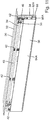
- a panel splitter carries in FIG. 1 It comprises a feed table 12, an extraction table 14 consisting of several segments, and a machine table 16 arranged between the feed table 12 and the removal table 14.
- the feed table 12 consists of a multiplicity of roller rails, the removal table 14 and the machine table 16 On the other hand, they are designed as air cushion tables.
- a dividing line 18 is provided, which is formed as a sawing gap, in FIG. 1 but only shown as a dotted line.
- a sawing device can be moved. In one embodiment, not shown, the division does not take place by means of a saw, but for example by means of a milling cutter.
- a pressure bar device 20 is present in a region above the split line 18. This comprises two laterally arranged from the machine table 16 vertical stand 22, by means of which the pressure bar means 20 on a floor (without reference numerals) is gestural. The pressure beam device 20 will be discussed in more detail below.
- To the panel splitter 10 also includes a conveyor in the form of a program pusher 24 A, on lateral rails 26 along a conveying direction 28th can be moved by means of a drive, not shown.
- the Aufteilline 18 extends between the two lateral rails 26. It can also be referred to as "cutting area”.
- On the side facing the machine table 16 side of the program pusher 24 a plurality of collets 30 A are arranged, of which in the present case for reasons of clarity, however, only one is provided with a reference numeral. It can easily be seen that the conveying direction 28 is orthogonal to the dividing line 18.
- To the conveyor further includes a program slider in the form of a carriage 24 B, which is connected to the in FIG.
- 1 right rail 26 is slidably held in the conveying direction 28 and to which a special collet 30 B is attached.
- the carriage 24 B and the program pusher 24 A can be operated independently.
- the collets 30 A and 30 B can be raised and lowered relative to the program pusher 24 A and the carriage 24 B.
- the pressure beam device 20 has a C-shaped support 32, the two vertical legs 34 and a horizontal base 36 includes.
- the C-shaped support 32 is attached to the uprights 22 at its axial ends.
- the pressure bar device 20 has a first Pressure bar 38 and a second and to the first pressure bar 38 identical pressure bar 40.
- the two pressure bars 38 and 40 are, for example, off FIG. 7 it can be seen, in each case around an elongated plate-like element, which is made for example of a steel sheet.
- the pressure bars 38 and 40 are held by means of linear guides 42 and 44 vertically displaceable on the two vertical legs 34 of the C-shaped support 32.
- the two pressure bars 38 and 40 are thus held on the common C-shaped carrier 32.
- the first pressure bar 38 is connected at its two end faces in each case via a first connecting rod 46, which in this respect forms a crank drive, with a first coupling shaft 48.
- the second pressure bar 40 is also connected at its two end faces in each case via a second connecting rod 50, which also forms a crank mechanism so far, with a second coupling shaft 52.
- the two coupling shafts 48 and 52 are arranged on the upper side of the horizontal base 36 of the C-shaped support 32.
- Each pressure bar 38 and 40 are assigned in the present embodiment, four pneumatic cylinders whose cylinder housing (without reference numeral) is attached to the carrier 32, whereas the piston rod (without reference numerals) is attached to the respective pressure bar 38 and 40 respectively.
- the pneumatic cylinders are arranged in the region of the linear guides 42 and 44 and in the drawing only in FIG. 8 and there only in one place, namely in the FIG. 8 outermost right and front linear guide 42 shown.
- the pneumatic cylinder shown there has the reference numeral 53.
- Each of the four pneumatic cylinders 53 forms a partial drive for him respectively associated pressure bars 38 and 40, and all four pneumatic cylinders 53 of a pressure bar 38 and 40 together form its "total drive".
- the plate dividing system 10 operates in principle as follows: a lying on the feed table 12 large-sized plate-shaped workpiece 54 is gripped at its seen in the conveying direction 28 rear edge of the collets 30 A of the program pusher 24 A. By a movement of the program pusher 24 A, the workpiece 54 is then moved in the conveying direction 28 to the dividing line 18. By a movement of the saw, the workpiece 54 is then processed. During such processing, depending on the type of processing, both pressure bars 38 and 40 or even only one of the two pressure bars 38 and 40 lowered by an actuation of the pneumatic cylinder 53 to the workpiece 54. As a result, the workpiece 54 is clamped between the pressure bar 38 and / or 40 and the machine table 16.
- the workpiece 54 is free and can be pushed for example by means of the program pusher 24 A to the removal table 14.
- a user manually pulls the machined workpiece 54 onto the unloading table 14, or the workpiece 54 is advanced by an automatic conveyor, not shown, such as a robot.
- FIG. 3 An operating situation in a first type of machining of the workpiece 54 is in FIG. 3 shown: this type of processing is called "front scratching". In such a front scraping cut only the front edge 56 A of the workpiece 54 seen in the conveying direction 28 is processed.
- the length of the material removal on the workpiece 54 is smaller than the thickness of the saw blade, whose center plane in FIG. 3 and the following figures by a dash-dot line with the reference numeral 58 is indicated.
- the workpiece 54 is still held by the collets 30 A of the program pusher 24 A. While the first pressure bar 38, which is arranged on the feed table 12 facing side of the Aufteilline 18 is lowered onto the workpiece 54 and this thereby clamped against the machine table 16, the second pressure bar 40, which on the discharge table 14 side facing the Aufteilline 18 is arranged lowered to the machine table 16. This prevents that the sawdust resulting from the front scraping cut reaches the unloading table 14. The second pressure bar 40 thus acts as a dust curtain.
- FIG. 3 One recognizes FIG. 3 in that a closed channel 60 is formed by the C-shaped carrier 32 and the two pressure bars 38 and 40.
- a wall element 62 can be arranged between the two pressure bars 38 and 40 ( FIG. 2 ), whose edges abut the two pressure bars 38 and 40.
- the wall element 62 is stationary, so that the two pressure bars 38 and 40 slide along the wall element 62 during their vertical movement.
- the wall element is formed as an elastic element, which is arranged wist between the two pressure bars.
- FIGS. 4 and 5 A second operating situation show the FIGS. 4 and 5
- a "rear scratch cut” is performed on the rear edge 56 B of the workpiece 54 seen in the conveying direction 28.
- the workpiece 54 from the program pusher 24 A and the collets 30 A pushed so far in the conveying direction 28 until its seen in the conveying direction 28 rear edge 56 B in the region of the median plane 58 of the saw blade.
- the one in the FIGS. 4 and 5 lowered second right pressure bar 40 on the workpiece 54, whereby the workpiece 54 is clamped between the pressure bar 40 and the machine table 16, and the program pusher 24 A with the collets 30 A retracted, and then the first pressure bar 38 is lowered onto the machine table 16 .
- a scratched cut can be carried out, in which case a very well sealed channel 60 is formed by means of which the sawdust resulting from the scratching cut can be extracted with high efficiency.
- a characteristic of the present panel dividing installation 10 is of particular importance: it can be seen from the figures that the distance A1 of the first pressure bar 38 from the dividing line 18 differs from the distance A2 of the second pressure bar 40 from the dividing line 18 ( FIG. 5 ). More specifically, the distance A1 of the first pressure bar 38 from the split line 18 is smaller than the distance A2 of the second pressure bar 40 from the split line 18. Thus, the center plane 58 of the saw blade is not centered to the pressure beam device 20th This has the advantage that when viewed in the conveying direction 28 front ends of the collets 30 A, when they have a workpiece 54 for a rear scrape along the FIGS.
- FIG. 6 A third operating situation shows FIG. 6 : this is a normal "separation cut".
- a workpiece 54 is positioned by the program pusher 24 A with the collets 30 A in a desired relative position to the split line 18 and the center plane 58 of the saw blade. Then, the two pressure bars 38 and 40 are lowered onto the workpiece 54, and the separating cut is performed.
- FIG. 9 is a representation similar to FIG. 2 However, a second embodiment of a pressure beam device 20.
- the carrier 32 has no C-shaped but a T-shaped cross-section.
- this pressure bar means 20 has a housing 63 having a C-shaped cross-section, which surrounds the pressure bars 38 and 40, the coupling shafts 48 and 52 and the upper area of the T-shaped carrier 32.
- the pressure bar 38 is not formed by a straight plate, but having an L-shaped cross-section plate comprising a vertical portion 64 A and a present at the lower end of the bend, which forms a horizontal portion 66 A.
- a first U-shaped wall element 62 A is arranged between the free edge of the Umbugs 66 and an existing at the bottom of the vertical leg 34 extension bar 68 in the present case. This is attached to the extension bar 68.
- FIG. 9 shows, between the extension bar 68 and the free edge of the Umbugs 66 B of the second pressure bar 40 also a-shaped wall element 62 B is arranged.
- FIG. 9 shown pressure bar means 20 is the same as that in connection with the FIGS. 2 to 8 shown pressure bar device 20th
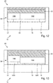
- a third embodiment of a Plattenaufteilstrom 10 and a pressure beam device 20 belonging thereto is in the FIGS. 12 and 13 shown.
- the carrier 32 can have both a C-shaped cross section and a T-shaped cross section.
- the essential difference of the third embodiment compared with the previously described embodiments is that the first pressure bar 38 visible there, seen in the direction of the split line 18, has two or more independently movable segments 70 A and 70 B. Also in the FIGS. 12 and 13 However, not visible second pressure bar 40 has corresponding independently movable segments.
- each segment of a pressure bar 38 or 40 has its own drive or its own drives, which can be controlled independently of each other.
- the drives can be designed as indicated above.
- segment 70A adjacent to the angular ruler 31 extends over approximately one third of the dividing line 18, whereas that segment 70B which is spaced from the angular ruler 31 extends over approximately two thirds of the dividing line 18.
- FIG. 12 an operating situation is shown in which a single workpiece 54 is processed.
- the two segments 70 A and 70 B of the pressure bar 38 (and the corresponding segments of the pressure bar 40) are the same controlled, in such a way that they clamp the workpiece 54 against the machine table 16.
- FIG. 13 another operating situation is shown in which, seen in the conveying direction 28, two adjacent workpieces 54 A and 54 B to be processed, the workpiece 54 A is significantly narrower, but thicker than the workpiece 54 B.
- the workpiece 54 A a bit narrower than the one in FIG. 13 left segments 70 A of the pressure bars 38 and 40
- the workpiece 54 B is slightly narrower than that in FIG. 13 right segments 70 B of the pressure bars 38 and 40.
- This will allow the in FIG. 13 left workpiece 54 A only by the segment 70 A of the pressure bars 38 and 40 is clamped, whereas the in FIG. 13 right workpiece 54 B only by the segment 70 B of the pressure bars 38 and 40 is clamped.
- the different thickness workpieces 54 A and 54 B they can thus be processed simultaneously, for example, the workpiece 54 A by a cross section and the workpiece 54 B by a post-cut.
- a workpiece is held by the relatively wide program pusher 24 A and there arranged collets 30 A and an adjacent workpiece is held by the side carriage 24 B with its special collet 30 B, and both workpieces are divided simultaneously.
- a workpiece is held by the relatively wide program pusher 24 A and there arranged collets 30 A and an adjacent workpiece is held by the side carriage 24 B with its special collet 30 B, and both workpieces are staggered, ie successively, divided up.
- FIG. 14 A fourth embodiment of a panel divider 10 or a pressure beam unit 20 is shown in FIG FIG. 14 shown. This is similar to the embodiment of FIGS. 12 and 13 , but with the difference that not only two segments 70 A and 70 B are present, but a total of 19 identically formed segments 70 A to 70 S. All segments 70 A to 70 S of a pressure bar 38 and 40 can be independently lowered and raised are therefore independent of each other controllable drives. Since each individual segment 70 A - 70 S has only a low weight and has to apply a low clamping force on the workpiece 54, the drive can be comparatively small.
- FIG. 14 One recognizes FIG. 14 in that, here too, the two adjacent workpieces 54 A and 54 B can be securely clamped against the machine table 16 despite their different thicknesses.
Description
Die Erfindung betrifft eine Plattenaufteilanlage nach dem Oberbegriff des Anspruchs 1.The invention relates to a panel splitter according to the preamble of claim 1.
Übliche Plattenaufteilanlagen umfassen einen Zuführtisch, einen Entnahmetisch, und einen zwischen Entnahmetisch und Zuführtisch angeordneten Maschinentisch. In dem Maschinentisch befindet sich eine Aufteillinie, meist in Form eines Aufteilspalts. Durch diesen kann eine Säge mit einem Sägeblatt oder ein Fräser mit einem Fräskopf längs zur Aufteillinie bewegt werden. Oberhalb von dem Maschinentisch ist ein Druckbalken angeordnet, der dazu dient, während eines Aufteilvorgangs ein Werkstück zu fixieren sowie die bei der Aufteilung entstehenden Späne zu erfassen. Hierzu wird der Druckbalken vertikal in Richtung auf den Maschinentisch abgesenkt, wodurch das Werkstück zwischen Druckbalken und Maschinentisch verklemmt wird.Conventional panel dividing systems comprise a feed table, a removal table, and a machine table arranged between the removal table and the feed table. In the machine table there is a dividing line, usually in the form of a dividing gap. Through this a saw with a saw blade or a milling cutter with a milling head can be moved along the dividing line. Above the machine table, a pressure bar is arranged, which serves to fix a workpiece during a splitting operation and to detect the chips formed during the splitting. For this purpose, the pressure bar is lowered vertically in the direction of the machine table, whereby the workpiece between the pressure bar and machine table is jammed.
Die
Die
Die
Die
Die
Aufgabe der vorliegenden Erfindung ist es, eine Plattenaufteilanlage zu schaffen, welche mit hoher Dynamik betrieben werden kann.Object of the present invention is to provide a Plattenaufteilanlage, which can be operated with high dynamics.
Diese Aufgabe wird durch eine Plattenaufteilanlage mit den Merkmalen des Anspruchs 1 gelöst. Vorteilhafte Weiterbildungen der Erfindung sind in Unteransprüchen angegeben. Darüber hinaus finden sich für die Erfindung wichtige Merkmale in der nachfolgenden Beschreibung sowie in der Zeichnung. Die Merkmale können dabei sowohl in Alleinstellung als auch in ganz unterschiedlichen Kombinationen für die Erfindung wichtig sein, ohne dass hierauf nochmals explizit hingewiesen wird.This object is achieved by a panel splitter with the features of claim 1. Advantageous developments of the invention are specified in subclaims. In addition, find important features for the invention in the following description and in the drawing. The features may be important for the invention both alone and in completely different combinations, without being explicitly referred to again.
Bei der erfindungsgemäßen Plattenaufteilanlage befindet sich der Antrieb nicht seitlich, sondern direkt über dem Maschinentisch bzw. in dem dort oberhalb von der Aufteillinie vorhandenen Bereich des parallel zur Aufteillinie verlaufenden stationären Trägers. Dies hat den Vorteil, dass die Distanz zwischen dem Antrieb und den Stellen, an denen die Reaktionskräfte in den Druckbalken eingeleitet werden, vergleichsweise gering ist, wodurch die sonst auftretenden und den Druckbalken verformenden Momente reduziert werden. Damit kann der Druckbalken einfacher und leichter gebaut werden, wodurch seine Dynamik, also die Geschwindigkeit, mit der er auf- und ab bewegt werden kann, erhöht wird. Erfindungsgemäß ist ferner, dass der erste Druckbalken in Richtung der Aufteillinie gesehen mindestens zwei unabhängig voneinander bewegbare Segmente aufweist, wobei der Antrieb einen Kurbeltrieb umfasst und die Plattenaufteilanlage zwei Programmschieber umfasst, wobei einer der Programmschieber ein seitlicher Schlitten ist. Hierdurch kann der Tatsache Rechnung getragen werden, dass ein Bedarf bestehen kann, dass unterschiedlich dicke Werkstücke gleichzeitig bearbeitet werden. Durch eine solche Segmentierung des Druckbalkens können auch solche Aufteilvorgänge sicher durchgeführt werden.In the panel splitter according to the invention, the drive is not laterally, but directly above the machine table or in which there above the Aufteillinie existing area of parallel to the dividing line extending stationary support. This has the advantage that the distance between the drive and the points at which the reaction forces are introduced into the pressure bar, is comparatively low, whereby the otherwise occurring and the pressure beam deforming moments are reduced. Thus, the pressure bar can be built easier and lighter, whereby its dynamics, so the speed with which it can be moved up and down, is increased. According to the invention, furthermore, the first pressure bar has at least two independently movable segments, viewed in the direction of the dividing line, wherein the drive comprises a crank drive and the panel dividing installation comprises two program pushers, one of the program pushers being a lateral slide. This can accommodate the fact that there may be a need for work pieces of different thicknesses to be processed simultaneously. By such a segmentation of the pressure bar and such division operations can be performed safely.
Im einfachsten Fall befindet sich der Antrieb zentral in der Mitte zwischen zwei seitlichen Maschinenfüßen, an denen der Träger, an dem der Druckbalken befestigt ist, gehalten ist. Denkbar ist aber auch, dass bei einem solchen zentralen Antrieb dieser etwas in Richtung zu einem Winkellineal hin versetzt angeordnet ist, da vom Druckbalken zu fixierende Werkstücke meist eher benachbart zu einem solchen Winkellineal auf dem Maschinentisch liegen.In the simplest case, the drive is located centrally in the middle between two lateral machine feet, on which the carrier to which the pressure bar is attached, is held. It is also conceivable, however, that in such a central drive, this is offset somewhat in the direction of an angular ruler, since workpieces to be fixed from the pressure bar are usually more adjacent to such an angular ruler on the machine table.
Vorgeschlagen wird ferner, dass der Antrieb eine Mehrzahl von Teil-Antrieben umfasst. Derartige Teil-Antriebe können relativ einfach und klein sein, da sie nur einen Teil-Beitrag zur Bewegung des Druckbalkens leisten müssen. Ferner wird die Distanz zwischen dem jeweiligen Teil-Antrieb und den Stellen, an denen Reaktionskräfte in den Druckbalken eingeleitet werden, nochmals reduziert, wodurch die den Druckbalken verformenden Momente nochmals reduziert werden.It is also proposed that the drive comprises a plurality of sub-drives. Such partial drives can be relatively simple and small, as they only have a partial contribution to perform the movement of the pressure beam. Further, the distance between the respective part-drive and the points at which reaction forces are introduced into the pressure bar, further reduced, whereby the moments deforming the pressure bar are further reduced.
Vorgeschlagen wird ferner, dass die Teil-Antriebe mechanisch miteinander gekoppelt sind, beispielsweise durch eine Koppelwelle. Auf diese Weise werden die Teil-Antriebe miteinander synchronisiert, so dass sich der Druckbalken trotz vergleichsweise geringer Steifigkeit gleichmäßig bewegt.It is further proposed that the partial drives are mechanically coupled to each other, for example by a coupling shaft. In this way, the part-drives are synchronized with each other, so that the pressure bar moves smoothly despite comparatively low rigidity.
Vorgeschlagen wird ferner, dass der Antrieb einen Kurbeltrieb umfasst. Dies ist eine einfache und stabile Art eines Antriebs. Darüber hinaus kann zum Antrieb ein Drehmotor verwendet werden, also beispielsweise auch ein elektrischer Motor, was ebenfalls der Dynamik des Druckbalkens zugutekommt und die Ansteuerung gegenüber beispielsweise einem pneumatischen Antrieb vereinfacht. Der Kurbeltrieb kann aber auch einfach dazu dienen, mehrere Teil-Antriebe mechanisch miteinander zu koppeln, in dem die Kurbeltriebe an einer gemeinsamen Koppelwelle angreifen.It is also proposed that the drive comprises a crank mechanism. This is a simple and stable type of drive. In addition, a rotary motor can be used to drive, so for example, an electric motor, which also benefits the dynamics of the pressure bar and simplifies the control over, for example, a pneumatic drive. However, the crank mechanism can also simply serve to mechanically couple a plurality of sub-drives together, in which the crank drives engage a common coupling shaft.
Vorgeschlagen wird ferner, dass jedem Segment ein eigener Antrieb zugeordnet ist. Die unabhängige Beweglichkeit der einzelnen Segmente kann auf diese Weise besonders einfach realisiert werden.It is also proposed that each segment has its own drive. The independent mobility of the individual segments can be realized particularly easily in this way.
Vorgeschlagen wird ferner, dass mindestens zwei Segmente in Richtung der Aufteillinie gesehen unterschiedlich lang sind. Insbesondere kann ein zu einem Winkellineal benachbartes Segment kürzer sein als ein von diesem Winkellineal entfernt angeordnetes Segment. Hierdurch wird berücksichtigt, dass in der Praxis dann, wenn zwei Werkstücke gleichzeitig aufgeteilt werden sollen, eines dieser Werkstücke meist streifenförmig, also vergleichsweise schmal ist, und dieses Werkstück meist am Winkellineal angelegt wird. Beispielsweise können das streifenförmige Werkstück im Rahmen eines "Querschnitts" (auch "Zweitschnitt" genannt) und das eher breite Werkstück im Rahmen eines "Längsschnitts" (auch "Erstschnitts" genannt) oder "Nachschnitts" (auch "Drittschnitt" genannt) bearbeitet werden.It is also proposed that at least two segments, seen in the direction of the split line, have different lengths. In particular, a segment adjacent to an angular ruler may be shorter than one of these Angular ruler remotely located segment. This takes into account that in practice, when two workpieces are to be split simultaneously, one of these workpieces is usually strip-shaped, ie comparatively narrow, and this work piece is usually applied to the angle ruler. For example, the strip-shaped workpiece in the context of a "cross-section" (also called "second cut") and the rather wide workpiece as part of a "longitudinal section" (also called "first cut") or "re-cut" (also called "third cut") can be edited.
Vorgeschlagen wird ferner, dass die Plattenaufteilanlage eine Fördereinrichtung zum Bewegen eines Werkstücks längs zu einer Förderrichtung, die orthogonal zur Aufteillinie liegt, umfasst, und dass sie einen zweiten Druckbalken umfasst, wobei der erste Druckbalken in Förderrichtung gesehen auf der einen Seite und der zweite Druckbalken in Förderrichtung gesehen auf der anderen Seite der Aufteillinie angeordnet sind, und wobei die beiden Druckbalken unabhängig voneinander bewegbar sind. Diese besonders vorteilhafte Weiterbildung der erfindungsgemäßen Plattenaufteilanlage gestattet es beispielsweise, sogenannte Kratzschnitte sowohl an einem in Förderrichtung gesehen vorderen als auch in einem in Förderrichtung gesehen hinteren Rand eines Werkstücks zuverlässig durchzuführen, ohne dass eine starke Verschmutzung der Plattenaufteilanlage durch beidem aufteilen entstehenden Material Staub zu befürchten ist. Einer der beiden Druckbalken fungiert nämlich als so genannter "Staubschutzvorhang". Kratzschnittes sind solche Schnitte, bei denen von einem Sägeblatt an einem Rand eines Werkstücks eine geringere Werkstücklänge abgetragen wird als das Sägeblatt dick ist.It is also proposed that the panel-splitting installation comprises a conveyor for moving a workpiece longitudinally to a conveying direction which is orthogonal to the dividing line, and that it comprises a second pressure bar, the first pressure bar being seen on one side and the second pressure bar in the conveying direction Seen conveying direction are arranged on the other side of the Aufteillinie, and wherein the two pressure bars are independently movable. This particularly advantageous development of the panel dividing system according to the invention makes it possible, for example, to carry out so-called scratching cuts reliably both on a front side viewed in the conveying direction and in a rear edge of a workpiece as seen in the conveying direction without fear of heavy contamination of the panel dividing system due to both dividing the resulting material dust , One of the two pressure bars acts as a so-called "dust protection curtain". Scratch cuts are those cuts in which a smaller workpiece length is removed by a saw blade at an edge of a workpiece than the saw blade is thick.
Vorgeschlagen wird ferner, dass der erste Druckbalken und der zweite Druckbalken identisch ausgebildet sind. Hierdurch werden die Herstellkosten der Plattenaufteilanlage reduziert.It is further proposed that the first pressure bar and the second pressure bar are identical. As a result, the manufacturing costs of the panel splitter are reduced.
Vorgeschlagen wird ferner, dass die beiden Druckbalken an einem gemeinsamen Träger gehalten sind. Dies reduziert Eder ebenfalls die Herstellkosten. Darüber hinaus wird Bauraum eingespart.It is also proposed that the two pressure bars are held on a common carrier. This also reduces Eder's manufacturing costs. In addition, space is saved.
Vorgeschlagen wird ferner, dass der gemeinsame Träger im Querschnitt C-förmig ist. Ein solcher Träger ist in Bewegungsrichtung der beiden Druckbalken besonders steif. Dabei ist es besonders günstig, wenn die beiden Schenkel des Trägers seitlich außen von den beiden Druckbalken angeordnet sind, und der Antrieb bzw. die Antriebe im Inneren des Trägers angeordnet sind. Dies hat optische Vorteile, führt aber auch zu einer geschützten Anordnung von Führungen und Antrieben.It is also proposed that the common carrier is C-shaped in cross-section. Such a carrier is particularly stiff in the direction of movement of the two pressure bars. It is particularly advantageous if the two legs of the carrier are arranged laterally outside of the two pressure bars, and the drive or the drives are arranged in the interior of the carrier. This has optical advantages, but also leads to a protected arrangement of guides and drives.
Vorgeschlagen wird ferner, dass der gemeinsame Träger im Querschnitt T-förmig ist. Ein solcher Träger ist ebenfalls steif, baut jedoch insgesamt kleiner und leichter.It is also proposed that the common carrier is T-shaped in cross-section. Such a carrier is also stiff, but builds overall smaller and lighter.
Vorgeschlagen wird ferner, dass zwischen den Druckbalken ein Wandelement angeordnet ist, welches eine obere Begrenzungswand eines Absaugkanals bildet. Damit wird ein besonders dichter und damit effizienter Absaugkanal geschaffen.It is further proposed that between the pressure bar, a wall element is arranged, which forms an upper boundary wall of a suction channel. This creates a particularly dense and therefore efficient suction channel.
Vorgeschlagen wird ferner, dass sich der Abstand des ersten Druckbalkens von der Aufteillinie von dem Abstand des zweiten Druckbalkens von der Aufteillinie unterscheidet.It is also proposed that the distance of the first pressure beam from the split line differs from the distance of the second pressure beam from the split line.
Dies hat insbesondere dann Vorteile, wenn eine Fördereinrichtung, die einen Programmschieber mit Spannzangen umfasst, die Werkstücke von einem Zuführtisch zur Aufteillinie fördert. Wenn die Aufteillinie näher zu jenem Druckbalken ist, der in Richtung des Programmschiebers angeordnet ist, als zu dem anderen Druckbalken, besteht ein geringeres Kollisionsrisiko der Fingern von Spannzangen mit dem vom Programmschieber entfernt angeordneten Druckbalken dann, wenn sich der Programmschieber in seiner zur Aufteillinie benachbarten Endstellung befindet.This has particular advantages when a conveyor that includes a program pusher with collets that conveys workpieces from a feed table to the split line. If the Aufteillinie is closer to that pressure bar, which is arranged in the direction of the program pusher, as to the other pressure bar, there is less risk of collision of the fingers of collets with the pressure bar remote from the program slider when the program pusher in its adjacent to the Aufteillinie end position located.
Nachfolgend werden Ausführungsformen der Erfindung unter Bezugnahme auf die beiliegende Zeichnung erläutert. In der Zeichnung zeigen:
-
Figur 1 eine Draufsicht auf eine Plattenaufteilanlage mit einem Maschinentisch und einer Druckbalkeneinrichtung; -
Figur 2 einen schematischen Schnitt durch den Maschinentisch und die Druckbalkeneinrichtung vonFigur 1 , wobei auch ein C-förmiger Träger sichtbar ist; -
Figur 3 einen nochmals vereinfachten schematischen Schnitt durch den Maschinentisch, wobei die Druckbalkeneinrichtung vonFigur 2 für eine erste Betriebssituation angesteuert ist; -
Figur 4 eine Darstellung ähnlichFigur 3 , wobei die Druckbalkeneinrichtung für eine zweite Betriebssituation angesteuert ist; -
Figur 5 eine Darstellung ähnlichFigur 4 , wobei die Druckbalkeneinrichtung ebenfalls für die zweite Betriebssituation angesteuert ist; -
Figur 6 eine Darstellung ähnlichFigur 3 , wobei die Druckbalkeneinrichtung für eine dritte Betriebssituation angesteuert ist; -
Figur 7 eine perspektivische Darstellung der Druckbalkeneinrichtung vonFigur 2 ; -
Figur 8 eine perspektivische Darstellung der Druckbalkeneinrichtung vonFigur 7 , jedoch ohne den C-förmigen Träger; -
Figur 9 eine Darstellung ähnlich zuFigur 2 einer zweiten Ausführungsform einer Druckbalkeneinrichtung mit einem T-förmigen Träger; -
Figur 10Figur 9 ; -
Figur 11 eine perspektivische Darstellung der Druckbalkeneinrichtung vonFigur 9 ; -
Figur 12 -
Figur 13 eine Darstellung ähnlich zuFigur 12 mit der Druckbalkeneinrichtung in einer vierten Betriebssituation; und -
Figur 14Figur 12 einer vierten Ausführungsform einer Druckbalkeneinrichtung.
-
FIG. 1 a plan view of a Plattenaufteilanlage with a machine table and a pressure bar device; -
FIG. 2 a schematic section through the machine table and the pressure beam device ofFIG. 1 wherein also a C-shaped support is visible; -
FIG. 3 a simplified schematic section through the machine table, the pressure bar device ofFIG. 2 is activated for a first operating situation; -
FIG. 4 a representation similarFIG. 3 , wherein the pressure bar device is activated for a second operating situation; -
FIG. 5 a representation similarFIG. 4 , wherein the pressure bar device is also activated for the second operating situation; -
FIG. 6 a representation similarFIG. 3 , wherein the pressure bar device is activated for a third operating situation; -
FIG. 7 a perspective view of the pressure bar device ofFIG. 2 ; -
FIG. 8 a perspective view of the pressure bar device ofFIG. 7 but without the C-shaped carrier; -
FIG. 9 a representation similar toFIG. 2 a second embodiment of a pressure beam device with a T-shaped carrier; -
FIG. 10 a partial section through the pressure beam device ofFIG. 9 ; -
FIG. 11 a perspective view of the pressure bar device ofFIG. 9 ; -
FIG. 12 a schematic front view of a third embodiment of a pressure bar device in a third operating situation; -
FIG. 13 a representation similar toFIG. 12 with the pressure bar device in a fourth operating situation; and -
FIG. 14 a representation similar toFIG. 12 a fourth embodiment of a pressure bar device.
In den Figuren sind funktionsäquivalente Elemente und Bereiche auch in unterschiedlichen Ausführungsformen mit den gleichen Bezugszeichen bezeichnet.In the figures functionally equivalent elements and regions are also designated in different embodiments with the same reference numerals.
Eine Plattenaufteilanlage trägt in
In dem Maschinentisch 16 ist eine Aufteillinie 18 vorhanden, die als ein Sägespalt ausgebildet ist, in
In einem Bereich oberhalb von der Aufteillinie 18 ist eine Druckbalkeneinrichtung 20 vorhanden. Diese umfasst zwei seitlich vom Maschinentisch 16 angeordnet vertikale Ständer 22, mittels denen die Druckbalkeneinrichtung 20 auf einem Boden (ohne Bezugszeichen) geständert ist. Auf die Druckbalkeneinrichtung 20 wird weiter unten noch stärker im Detail eingegangen werden.In the machine table 16, a
In a region above the
Zu der Plattenaufteilanlage 10 gehört auch eine Fördereinrichtung in Form eines Programmschiebers 24 A, der auf seitlichen Schienen 26 längs zu einer Förderrichtung 28 mittels eines nicht gezeigten Antriebs bewegt werden kann. Die Aufteillinie 18 erstreckt sich dabei zwischen den beiden seitlichen Schienen 26. Sie kann auch als "Schnittbereich" bezeichnet werden. Auf der zum Maschinentisch 16 hin weisenden Seite des Programmschiebers 24 sind eine Mehrzahl von Spannzangen 30 A angeordnet, von denen vorliegend aus Gründen der Übersichtlichkeit jedoch nur eine mit einem Bezugszeichen versehen ist. Man erkennt ohne weiteres, dass die Förderrichtung 28 orthogonal zur Aufteillinie 18 liegt. Zu der Fördereinrichtung gehört ferner ein Programmschieber in Form eines Schlittens 24 B, der an der in
Im Bereich der in
Aus
Out
Bei den beiden Druckbalken 38 und 40 handelt es sich, wie beispielsweise aus
Jedem Druckbalken 38 und 40 sind bei der vorliegenden Ausführungsform vier Pneumatikzylinder zugeordnet, deren Zylindergehäuse (ohne Bezugszeichen) an dem Träger 32 befestigt ist, wohingegen deren Kolbenstange (ohne Bezugszeichen) am jeweiligen Druckbalken 38 bzw. 40 befestigt ist. Die Pneumatikzylinder sind im Bereich der Linearführungen 42 bzw. 44 angeordnet und in der Zeichnung lediglich in
Durch die beiden Koppelwellen 48 und 52 wird sichergestellt, dass sich die Druckbalken 38 und 40 trotz der Mehrzahl von Pneumatikzylindern 53 gleichförmig bewegen. Ferner wird verhindert, dass ein Druckbalken 38 oder 40 oder beide Druckbalken 38 und 40 bei der Fixierung von Werkstücken mit unterschiedlicher Länge ungleichmäßig belastet werden. Aus
Die Plattenaufteilanlage 10 arbeitet im Grundsatz folgendermaßen: ein auf dem Zuführtisch 12 liegendes großformatiges plattenförmiges Werkstück 54 wird an seinem in Förderrichtung 28 gesehen hinteren Rand von den Spannzangen 30 A des Programmschiebers 24 A gegriffen. Durch eine Bewegung des Programmschiebers 24 A wird das Werkstück 54 dann in Förderrichtung 28 zur Aufteillinie 18 hin bewegt. Durch eine Bewegung der Säge wird dann das Werkstück 54 bearbeitet. Während einer solchen Bearbeitung werden, abhängig von der Art der Bearbeitung, beide Druckbalken 38 und 40 oder auch nur einer der beiden Druckbalken 38 und 40 durch eine Betätigung der Pneumatikzylinder 53 auf das Werkstück 54 abgesenkt. Hierdurch wird das Werkstück 54 zwischen dem Druckbalken 38 und/oder 40 und dem Maschinentisch 16 verklemmt. Nach dem Ende der Bearbeitung werden der oder die Druckbalken 38 und 40 wieder nach oben gefahren, wodurch das Werkstück 54 frei wird und beispielsweise mittels des Programmschiebers 24 A zum Entnahmetisch 14 geschoben werden kann. Möglich ist auch, dass ein Benutzer das bearbeitete Werkstück 54 von Hand auf den Entnahmetisch 14 zieht oder das Werkstück 54 durch eine nicht gezeigte automatische Fördereinrichtung, beispielsweise einen Roboter, weitergeführt bzw. bewegt wird.The
Eine Betriebssituation bei einer ersten Art der Bearbeitung des Werkstücks 54 ist in
Während eines solchen vorderen Kratzschnitts wird das Werkstück 54 weiterhin von den Spannzangen 30 A des Programmschiebers 24 A gehalten. Während der erste Druckbalken 38, der auf der dem Zuführtisch 12 zugewandten Seite der Aufteillinie 18 angeordnet ist, auf das Werkstück 54 abgesenkt wird und dieses hierdurch gegen den Maschinentisch 16 klemmt, wird der zweite Druckbalken 40, der auf der dem Entnahmetisch 14 zugewandten Seite der Aufteillinie 18 angeordnet ist, auf den Maschinentisch 16 abgesenkt. Hierdurch wird verhindert, dass der bei dem vorderen Kratzschnitt entstehende Sägestaub auf den Entnahmetisch 14 gelangt. Der zweite Druckbalken 40 wirkt also als Staubschutzvorhang.During such a front scratch cut, the
Man erkennt aus
Eine zweite Betriebssituation zeigen die
Im Zusammenhang mit dem hinteren Kratzschnitt ist eine Eigenschaft der vorliegenden Plattenaufteilanlage 10 von besonderer Bedeutung: aus den Figuren ist ersichtlich, dass sich der Abstand A1 des ersten Druckbalkens 38 von der Aufteillinie 18 von dem Abstand A2 des zweiten Druckbalkens 40 von der Aufteillinie 18 unterscheidet (
Dies hat den Vorteil, dass die in Förderrichtung 28 gesehen vorderen Enden der Spannzangen 30 A dann, wenn sie ein Werkstück 54 für einen hinteren Kratzschnitt entsprechend den
This has the advantage that when viewed in the conveying
Eine dritte Betriebssituation zeigt
In den ebenfalls diese zweite Ausführungsform darstellenden
Man erkennt aus den
Die grundsätzliche Funktionsweise der in
Eine dritte Ausführungsform einer Plattenaufteilanlage 10 bzw. einer hierzu gehörenden Druckbalkeneinrichtung 20 ist in den
Man erkennt aus den
In
Hierzu Folgendes: bei der Aufteilung von großformatigen plattenförmigen Werkstücken wird üblicherweise ein solches Werkstück zunächst durch Längsschnitte, die auch als Erstschnitte bezeichnet werden, in einzelne Streifen aufgeteilt. Diese Streifen werden dann um 90° gedreht und von der Säge durch Querschnitte, die auch als Zweitschnitte bezeichnet werden, weiter aufgeteilt. Einzelne der hieraus entstehenden Werkstücke werden eventuell nochmals um 90° gedreht und nochmals durch einen Nachschnitt, der auch als Drittschnitt bezeichnet wird, aufgeteilt. Durchaus möglich ist, dass sich hieran noch weitere Bearbeitungsschritte, beispielsweise Schnitte oder 5 Schnitte, anschließen.For this purpose: in the division of large-sized plate-shaped workpieces usually such a workpiece is first divided by longitudinal sections, which are also referred to as Erstschnitte, into individual strips. These strips are then rotated 90 ° and further divided by the saw by cross sections, which are also referred to as second cuts. Some of the resulting workpieces may be rotated 90 ° again and again divided by a re-cut, which is also referred to as a third cut. It is quite possible that this will be followed by further processing steps, such as cuts or 5 cuts.
Wenn der Abstand zwischen den Werkstücken 54 A und 54 B groß ist, können diese Werkstücke auch zeitversetzt nacheinander aufgeteilt werden. Voraussetzung hierfür ist jedoch ein zweiter Programmschieber oder eine Ausgestaltung ähnlich zu jener, wie sie in dem europäischen Patent
Eine vierte Ausführungsform einer Plattenaufteilanlage 10 bzw. einer Druckbalkeneinrichtung 20 ist in
Man erkennt aus
Claims (14)
- Panel dividing system (10) comprising a machine table (16), comprising a dividing line (18) present in the machine table (16), and comprising a pressure beam device (20) that is arranged in a region above the dividing line (18) and has at least one first pressure beam (38) which is held on a stationary support (32) extending preferably in parallel with the dividing line (18) and can be moved orthogonally with respect to a plane of the machine table (16) by means of at least one drive (53), the drive (53) and/or a guiding device (42) of the pressure beam device (20) being arranged in a region above the dividing line (18), and the first pressure beam (38), when viewed in the direction of the dividing line (18), having at least two segments (70) that can be moved independently of one another, characterized in that the panel dividing system (10) comprises two program feeders (24A, 24B), one of the program feeders being a lateral slide (24B), the drive (53) comprising a crank drive.
- Panel dividing system (10) according to claim 1, characterized in that the drive (53) comprises a plurality of partial drives.
- Panel dividing system (10) according to claim 2, characterized in that the partial drives (53) are mechanically coupled to one another (48, 52).
- Panel dividing system (10) according to any of the preceding claims, characterized in that each segment (70) is associated with a specific drive (53).
- Panel dividing system (10) according to any of the preceding claims, characterized in that at least two segments (70A, 70B) are different lengths when viewed in the direction of the dividing line (18).
- Panel dividing system (10) according to any of the preceding claims, characterized in that it comprises a conveying device (24) for moving a workpiece (54) longitudinally with respect to a conveying direction (28) which is orthogonal with respect to the dividing line (18), and in that the pressure beam device (20) comprises a second pressure beam (40), the first pressure beam (38), when viewed in the conveying direction (28), being arranged on one side and the second pressure beam (40), when viewed in the conveying direction (28), being arranged on the other side of the dividing line (18), and it preferably being possible to move the two pressure beams (38, 40) independently of one another.
- Panel dividing system (10) according to claim 6, characterized in that the first pressure beam (38) and the second pressure beam (40) are identical, preferably the mirror image of one another.
- Panel dividing system (10) according to claim 6 or claim 7, characterized in that the two pressure beams (38, 40) are held on a common support (32).
- Panel dividing system (10) according to claim 8, characterized in that the common support (32) has a C-shaped cross section.
- Panel dividing system (10) according to claim 8, characterized in that the common support (32) has a T-shaped cross section.
- Panel dividing system (10) according to any of claims 6 to 10, characterized in that a wall element (62) is arranged between the pressure beams (38, 40), which wall element forms an upper boundary wall of an extraction channel (60).
- Panel dividing system (10) according to any of claims 6 to 11, characterized in that the distance (A1) between the first pressure beam (38) and the dividing line (18) differs from the distance (A2) between the second pressure beam (40) and the dividing line (18).
- Method for operating a panel dividing system (10) according to any of the preceding claims, characterized in that a first workpiece having a first thickness and a second workpiece having a second thickness are simultaneously divided.
- Method for operating a panel dividing system according to any of claims 1 to 12, which system has at least two program feeders (24A, 24B) that are arranged next to one another and can be moved independently of one another, characterized in that a first workpiece is held by the first program feeder (24A) and a second workpiece is held by the second program feeder (24B) and positioned relative to the dividing line, and in that the workpieces are processed in a temporally offset manner.
Applications Claiming Priority (1)
| Application Number | Priority Date | Filing Date | Title |
|---|---|---|---|
| DE102015206660.6A DE102015206660A1 (en) | 2015-04-14 | 2015-04-14 | Beamsaw |
Publications (2)
| Publication Number | Publication Date |
|---|---|
| EP3081325A1 EP3081325A1 (en) | 2016-10-19 |
| EP3081325B1 true EP3081325B1 (en) | 2018-12-12 |
Family
ID=55754106
Family Applications (1)
| Application Number | Title | Priority Date | Filing Date |
|---|---|---|---|
| EP16164407.5A Active EP3081325B1 (en) | 2015-04-14 | 2016-04-08 | Panel cutting assembly |
Country Status (3)
| Country | Link |
|---|---|
| EP (1) | EP3081325B1 (en) |
| CN (1) | CN205816953U (en) |
| DE (1) | DE102015206660A1 (en) |
Families Citing this family (3)
| Publication number | Priority date | Publication date | Assignee | Title |
|---|---|---|---|---|
| DE102017113993A1 (en) * | 2017-06-23 | 2018-12-27 | Holz-Her Gmbh | sawing |
| EP4245448A3 (en) * | 2018-10-05 | 2023-11-22 | IMA Schelling Austria GmbH | Panel partitioning facility |
| IT202000032591A1 (en) * | 2020-12-29 | 2022-06-29 | Scm Group Spa | METHOD OF WITHDRAWING A PIECE FROM THE OUTPUT STATION OF A MACHINE FOR PROCESSING WOODEN AND SIMILAR PIECES AND RELATED MACHINE. |
Citations (5)
| Publication number | Priority date | Publication date | Assignee | Title |
|---|---|---|---|---|
| GB773141A (en) * | 1954-12-16 | 1957-04-24 | Schenck Gmbh Carl | Device for dividing a continuous web of loosely heaped materials, such as wood chips or shavings |
| GB1151522A (en) * | 1965-09-10 | 1969-05-07 | Blakesley Reid Hire Co Ltd | Power Tool Guiding Apparatus |
| EP1964653A1 (en) * | 2007-03-02 | 2008-09-03 | HOLZMA Plattenaufteiltechnik GmbH | Plate partitioning facility for partitioning plate-shaped workpieces and method for its operation |
| EP2111939A2 (en) * | 2008-04-21 | 2009-10-28 | Valter Naldi | Cutting machine |
| EP2251128A1 (en) * | 2009-05-14 | 2010-11-17 | Biesse S.p.A. | Machine for cutting panels of wood or similar |
Family Cites Families (11)
| Publication number | Priority date | Publication date | Assignee | Title |
|---|---|---|---|---|
| IT1120358B (en) * | 1979-05-22 | 1986-03-19 | Giben Impianti Spa | IMPROVEMENTS IN THE PANEL SAWS |
| AT386795B (en) * | 1986-05-27 | 1988-10-10 | Schelling & Co | PANEL CUTTING UNIT WITH A LONGITIES SAW AND A CROSS SAW |
| DE8626633U1 (en) * | 1986-10-08 | 1989-08-24 | Jenkner, Erwin, 7261 Gechingen, De | |
| DE3830857C1 (en) * | 1988-09-10 | 1990-01-04 | Erwin 7261 Gechingen De Jenkner | |
| IT1249228B (en) * | 1991-04-10 | 1995-02-21 | Giben Impianti Spa | BILATERAL PRESSER FOR PANEL SAWS. |
| JP4585110B2 (en) * | 2000-12-18 | 2010-11-24 | アミテック株式会社 | Traveling circular saw machine |
| AT500768A1 (en) * | 2004-09-03 | 2006-03-15 | Panhans Maschb Gmbh | PROCESSING FACILITY |
| ITBO20060672A1 (en) * | 2006-09-29 | 2008-03-30 | Giben Int Spa | MILLING MACHINE FOR WOODEN OR ASSEMBLY PANELS. |
| DE102008058162B4 (en) * | 2007-11-27 | 2018-02-22 | Schelling Anlagenbau Gmbh | sawing machine |
| ITBO20090024A1 (en) * | 2009-01-21 | 2010-07-22 | Biesse Spa | CUTTING MACHINE FOR CUTTING WOOD OR SIMILAR PANELS |
| DE202011101666U1 (en) * | 2011-05-27 | 2012-08-30 | Wilhelm Altendorf Gmbh & Co. Kg | Panel sizing saw with safety signal device |
-
2015
- 2015-04-14 DE DE102015206660.6A patent/DE102015206660A1/en not_active Ceased
-
2016
- 2016-04-08 EP EP16164407.5A patent/EP3081325B1/en active Active
- 2016-04-14 CN CN201620310826.2U patent/CN205816953U/en active Active
Patent Citations (5)
| Publication number | Priority date | Publication date | Assignee | Title |
|---|---|---|---|---|
| GB773141A (en) * | 1954-12-16 | 1957-04-24 | Schenck Gmbh Carl | Device for dividing a continuous web of loosely heaped materials, such as wood chips or shavings |
| GB1151522A (en) * | 1965-09-10 | 1969-05-07 | Blakesley Reid Hire Co Ltd | Power Tool Guiding Apparatus |
| EP1964653A1 (en) * | 2007-03-02 | 2008-09-03 | HOLZMA Plattenaufteiltechnik GmbH | Plate partitioning facility for partitioning plate-shaped workpieces and method for its operation |
| EP2111939A2 (en) * | 2008-04-21 | 2009-10-28 | Valter Naldi | Cutting machine |
| EP2251128A1 (en) * | 2009-05-14 | 2010-11-17 | Biesse S.p.A. | Machine for cutting panels of wood or similar |
Also Published As
| Publication number | Publication date |
|---|---|
| CN205816953U (en) | 2016-12-21 |
| DE102015206660A8 (en) | 2016-12-08 |
| EP3081325A1 (en) | 2016-10-19 |
| DE102015206660A1 (en) | 2016-10-20 |
Similar Documents
| Publication | Publication Date | Title |
|---|---|---|
| DE102007010207B4 (en) | Panel dividing plant for dividing plate-shaped workpieces, as well as methods for their operation | |
| EP1600254B1 (en) | Conveying unit for machine for working workpieces and method for machining such workpieces | |
| DE102009033649B4 (en) | Beamsaw | |
| EP2340147B1 (en) | Processing machine for six-sided processing | |
| WO2016045968A1 (en) | Machining device | |
| EP2158055B1 (en) | Saw device and method for sawing a workpiece | |
| EP2127829A1 (en) | Board separation assembly | |
| EP2275235B1 (en) | Device for dividing a large-format panel | |
| EP3081325B1 (en) | Panel cutting assembly | |
| EP3563959A1 (en) | Sawing device | |
| EP2098343A1 (en) | Processing device | |
| DE102009045017B4 (en) | Processing device and processing method | |
| AT519407B1 (en) | Processing plant for plates and the like and realized with this plant production line | |
| EP1990119A1 (en) | Horizontal panel saw | |
| DE3716666A1 (en) | Panel-dividing installation with a ripsaw and a cross-cut saw | |
| EP2711116B1 (en) | Pressure beam for a sawing device | |
| EP1683604A1 (en) | Feeding device for plateshaped workpieces and collet for use in such a feeding device | |
| DE102016120139B4 (en) | Method, machine tool and slot tool for multi-stroke progressive slitting of plate-shaped workpieces | |
| EP0292864B1 (en) | Wood-working machine | |
| EP3017923B1 (en) | System for producing or producing and handling of glazing bars and method using such a system | |
| EP4008508A1 (en) | Method for sawing at least one workpiece | |
| EP1764177B1 (en) | Apparatus for cutting glazing bars or the like to lenth and method for cutting glazing bars or the like | |
| DE10115653B4 (en) | Clamping system for clamping and possibly centering of profile frames in combination with a cleaning device with at least two processing units and associated method | |
| WO2019057658A1 (en) | Method for processing workpieces, computer program product, and workpiece processing system | |
| DE102017121958A1 (en) | Method for dividing a preferably plate-shaped workpiece |
Legal Events
| Date | Code | Title | Description |
|---|---|---|---|
| PUAI | Public reference made under article 153(3) epc to a published international application that has entered the european phase |
Free format text: ORIGINAL CODE: 0009012 |
|
| AK | Designated contracting states |
Kind code of ref document: A1 Designated state(s): AL AT BE BG CH CY CZ DE DK EE ES FI FR GB GR HR HU IE IS IT LI LT LU LV MC MK MT NL NO PL PT RO RS SE SI SK SM TR |
|
| AX | Request for extension of the european patent |
Extension state: BA ME |
|
| STAA | Information on the status of an ep patent application or granted ep patent |
Free format text: STATUS: REQUEST FOR EXAMINATION WAS MADE |
|
| 17P | Request for examination filed |
Effective date: 20170224 |
|
| RBV | Designated contracting states (corrected) |
Designated state(s): AL AT BE BG CH CY CZ DE DK EE ES FI FR GB GR HR HU IE IS IT LI LT LU LV MC MK MT NL NO PL PT RO RS SE SI SK SM TR |
|
| RIN1 | Information on inventor provided before grant (corrected) |
Inventor name: KRETEK, DAVID Inventor name: SCHMIDT, TIBOR Inventor name: ZIMBAKOV, DARKO Inventor name: KAISER, JONATHAN Inventor name: BLAICH, MARKUS |
|
| STAA | Information on the status of an ep patent application or granted ep patent |
Free format text: STATUS: EXAMINATION IS IN PROGRESS |
|
| 17Q | First examination report despatched |
Effective date: 20171013 |
|
| RAP1 | Party data changed (applicant data changed or rights of an application transferred) |
Owner name: HOMAG PLATTENAUFTEILTECHNIK GMBH |
|
| GRAP | Despatch of communication of intention to grant a patent |
Free format text: ORIGINAL CODE: EPIDOSNIGR1 |
|
| STAA | Information on the status of an ep patent application or granted ep patent |
Free format text: STATUS: GRANT OF PATENT IS INTENDED |
|
| INTG | Intention to grant announced |
Effective date: 20180627 |
|
| GRAS | Grant fee paid |
Free format text: ORIGINAL CODE: EPIDOSNIGR3 |
|
| GRAA | (expected) grant |
Free format text: ORIGINAL CODE: 0009210 |
|
| STAA | Information on the status of an ep patent application or granted ep patent |
Free format text: STATUS: THE PATENT HAS BEEN GRANTED |
|
| AK | Designated contracting states |
Kind code of ref document: B1 Designated state(s): AL AT BE BG CH CY CZ DE DK EE ES FI FR GB GR HR HU IE IS IT LI LT LU LV MC MK MT NL NO PL PT RO RS SE SI SK SM TR |
|
| REG | Reference to a national code |
Ref country code: GB Ref legal event code: FG4D Free format text: NOT ENGLISH |
|
| REG | Reference to a national code |
Ref country code: CH Ref legal event code: EP |
|
| REG | Reference to a national code |
Ref country code: AT Ref legal event code: REF Ref document number: 1075295 Country of ref document: AT Kind code of ref document: T Effective date: 20181215 |
|
| REG | Reference to a national code |
Ref country code: DE Ref legal event code: R096 Ref document number: 502016002750 Country of ref document: DE |
|
| REG | Reference to a national code |
Ref country code: IE Ref legal event code: FG4D Free format text: LANGUAGE OF EP DOCUMENT: GERMAN |
|
| REG | Reference to a national code |
Ref country code: NL Ref legal event code: MP Effective date: 20181212 |
|
| REG | Reference to a national code |
Ref country code: LT Ref legal event code: MG4D |
|
| PG25 | Lapsed in a contracting state [announced via postgrant information from national office to epo] |
Ref country code: FI Free format text: LAPSE BECAUSE OF FAILURE TO SUBMIT A TRANSLATION OF THE DESCRIPTION OR TO PAY THE FEE WITHIN THE PRESCRIBED TIME-LIMIT Effective date: 20181212 Ref country code: LV Free format text: LAPSE BECAUSE OF FAILURE TO SUBMIT A TRANSLATION OF THE DESCRIPTION OR TO PAY THE FEE WITHIN THE PRESCRIBED TIME-LIMIT Effective date: 20181212 Ref country code: LT Free format text: LAPSE BECAUSE OF FAILURE TO SUBMIT A TRANSLATION OF THE DESCRIPTION OR TO PAY THE FEE WITHIN THE PRESCRIBED TIME-LIMIT Effective date: 20181212 Ref country code: NO Free format text: LAPSE BECAUSE OF FAILURE TO SUBMIT A TRANSLATION OF THE DESCRIPTION OR TO PAY THE FEE WITHIN THE PRESCRIBED TIME-LIMIT Effective date: 20190312 Ref country code: BG Free format text: LAPSE BECAUSE OF FAILURE TO SUBMIT A TRANSLATION OF THE DESCRIPTION OR TO PAY THE FEE WITHIN THE PRESCRIBED TIME-LIMIT Effective date: 20190312 Ref country code: ES Free format text: LAPSE BECAUSE OF FAILURE TO SUBMIT A TRANSLATION OF THE DESCRIPTION OR TO PAY THE FEE WITHIN THE PRESCRIBED TIME-LIMIT Effective date: 20181212 Ref country code: HR Free format text: LAPSE BECAUSE OF FAILURE TO SUBMIT A TRANSLATION OF THE DESCRIPTION OR TO PAY THE FEE WITHIN THE PRESCRIBED TIME-LIMIT Effective date: 20181212 |
|
| PG25 | Lapsed in a contracting state [announced via postgrant information from national office to epo] |
Ref country code: AL Free format text: LAPSE BECAUSE OF FAILURE TO SUBMIT A TRANSLATION OF THE DESCRIPTION OR TO PAY THE FEE WITHIN THE PRESCRIBED TIME-LIMIT Effective date: 20181212 Ref country code: SE Free format text: LAPSE BECAUSE OF FAILURE TO SUBMIT A TRANSLATION OF THE DESCRIPTION OR TO PAY THE FEE WITHIN THE PRESCRIBED TIME-LIMIT Effective date: 20181212 Ref country code: GR Free format text: LAPSE BECAUSE OF FAILURE TO SUBMIT A TRANSLATION OF THE DESCRIPTION OR TO PAY THE FEE WITHIN THE PRESCRIBED TIME-LIMIT Effective date: 20190313 Ref country code: RS Free format text: LAPSE BECAUSE OF FAILURE TO SUBMIT A TRANSLATION OF THE DESCRIPTION OR TO PAY THE FEE WITHIN THE PRESCRIBED TIME-LIMIT Effective date: 20181212 |
|
| PG25 | Lapsed in a contracting state [announced via postgrant information from national office to epo] |
Ref country code: NL Free format text: LAPSE BECAUSE OF FAILURE TO SUBMIT A TRANSLATION OF THE DESCRIPTION OR TO PAY THE FEE WITHIN THE PRESCRIBED TIME-LIMIT Effective date: 20181212 |
|
| PG25 | Lapsed in a contracting state [announced via postgrant information from national office to epo] |
Ref country code: CZ Free format text: LAPSE BECAUSE OF FAILURE TO SUBMIT A TRANSLATION OF THE DESCRIPTION OR TO PAY THE FEE WITHIN THE PRESCRIBED TIME-LIMIT Effective date: 20181212 Ref country code: PT Free format text: LAPSE BECAUSE OF FAILURE TO SUBMIT A TRANSLATION OF THE DESCRIPTION OR TO PAY THE FEE WITHIN THE PRESCRIBED TIME-LIMIT Effective date: 20190412 Ref country code: PL Free format text: LAPSE BECAUSE OF FAILURE TO SUBMIT A TRANSLATION OF THE DESCRIPTION OR TO PAY THE FEE WITHIN THE PRESCRIBED TIME-LIMIT Effective date: 20181212 |
|
| PG25 | Lapsed in a contracting state [announced via postgrant information from national office to epo] |
Ref country code: IS Free format text: LAPSE BECAUSE OF FAILURE TO SUBMIT A TRANSLATION OF THE DESCRIPTION OR TO PAY THE FEE WITHIN THE PRESCRIBED TIME-LIMIT Effective date: 20190412 Ref country code: SM Free format text: LAPSE BECAUSE OF FAILURE TO SUBMIT A TRANSLATION OF THE DESCRIPTION OR TO PAY THE FEE WITHIN THE PRESCRIBED TIME-LIMIT Effective date: 20181212 Ref country code: EE Free format text: LAPSE BECAUSE OF FAILURE TO SUBMIT A TRANSLATION OF THE DESCRIPTION OR TO PAY THE FEE WITHIN THE PRESCRIBED TIME-LIMIT Effective date: 20181212 Ref country code: RO Free format text: LAPSE BECAUSE OF FAILURE TO SUBMIT A TRANSLATION OF THE DESCRIPTION OR TO PAY THE FEE WITHIN THE PRESCRIBED TIME-LIMIT Effective date: 20181212 Ref country code: SK Free format text: LAPSE BECAUSE OF FAILURE TO SUBMIT A TRANSLATION OF THE DESCRIPTION OR TO PAY THE FEE WITHIN THE PRESCRIBED TIME-LIMIT Effective date: 20181212 |
|
| REG | Reference to a national code |
Ref country code: DE Ref legal event code: R097 Ref document number: 502016002750 Country of ref document: DE |
|
| PLBE | No opposition filed within time limit |
Free format text: ORIGINAL CODE: 0009261 |
|
| STAA | Information on the status of an ep patent application or granted ep patent |
Free format text: STATUS: NO OPPOSITION FILED WITHIN TIME LIMIT |
|
| PG25 | Lapsed in a contracting state [announced via postgrant information from national office to epo] |
Ref country code: DK Free format text: LAPSE BECAUSE OF FAILURE TO SUBMIT A TRANSLATION OF THE DESCRIPTION OR TO PAY THE FEE WITHIN THE PRESCRIBED TIME-LIMIT Effective date: 20181212 Ref country code: SI Free format text: LAPSE BECAUSE OF FAILURE TO SUBMIT A TRANSLATION OF THE DESCRIPTION OR TO PAY THE FEE WITHIN THE PRESCRIBED TIME-LIMIT Effective date: 20181212 |
|
| 26N | No opposition filed |
Effective date: 20190913 |
|
| REG | Reference to a national code |
Ref country code: CH Ref legal event code: PL |
|
| REG | Reference to a national code |
Ref country code: BE Ref legal event code: MM Effective date: 20190430 |
|
| PG25 | Lapsed in a contracting state [announced via postgrant information from national office to epo] |
Ref country code: MC Free format text: LAPSE BECAUSE OF FAILURE TO SUBMIT A TRANSLATION OF THE DESCRIPTION OR TO PAY THE FEE WITHIN THE PRESCRIBED TIME-LIMIT Effective date: 20181212 Ref country code: LU Free format text: LAPSE BECAUSE OF NON-PAYMENT OF DUE FEES Effective date: 20190408 |
|
| PG25 | Lapsed in a contracting state [announced via postgrant information from national office to epo] |
Ref country code: CH Free format text: LAPSE BECAUSE OF NON-PAYMENT OF DUE FEES Effective date: 20190430 Ref country code: LI Free format text: LAPSE BECAUSE OF NON-PAYMENT OF DUE FEES Effective date: 20190430 |
|
| PG25 | Lapsed in a contracting state [announced via postgrant information from national office to epo] |
Ref country code: BE Free format text: LAPSE BECAUSE OF NON-PAYMENT OF DUE FEES Effective date: 20190430 Ref country code: FR Free format text: LAPSE BECAUSE OF NON-PAYMENT OF DUE FEES Effective date: 20190430 |
|
| PG25 | Lapsed in a contracting state [announced via postgrant information from national office to epo] |
Ref country code: TR Free format text: LAPSE BECAUSE OF FAILURE TO SUBMIT A TRANSLATION OF THE DESCRIPTION OR TO PAY THE FEE WITHIN THE PRESCRIBED TIME-LIMIT Effective date: 20181212 |
|
| PG25 | Lapsed in a contracting state [announced via postgrant information from national office to epo] |
Ref country code: IE Free format text: LAPSE BECAUSE OF NON-PAYMENT OF DUE FEES Effective date: 20190408 |
|
| GBPC | Gb: european patent ceased through non-payment of renewal fee |
Effective date: 20200408 |
|
| PG25 | Lapsed in a contracting state [announced via postgrant information from national office to epo] |
Ref country code: GB Free format text: LAPSE BECAUSE OF NON-PAYMENT OF DUE FEES Effective date: 20200408 |
|
| PG25 | Lapsed in a contracting state [announced via postgrant information from national office to epo] |
Ref country code: CY Free format text: LAPSE BECAUSE OF FAILURE TO SUBMIT A TRANSLATION OF THE DESCRIPTION OR TO PAY THE FEE WITHIN THE PRESCRIBED TIME-LIMIT Effective date: 20181212 |
|
| PG25 | Lapsed in a contracting state [announced via postgrant information from national office to epo] |
Ref country code: HU Free format text: LAPSE BECAUSE OF FAILURE TO SUBMIT A TRANSLATION OF THE DESCRIPTION OR TO PAY THE FEE WITHIN THE PRESCRIBED TIME-LIMIT; INVALID AB INITIO Effective date: 20160408 Ref country code: MT Free format text: LAPSE BECAUSE OF FAILURE TO SUBMIT A TRANSLATION OF THE DESCRIPTION OR TO PAY THE FEE WITHIN THE PRESCRIBED TIME-LIMIT Effective date: 20181212 |
|
| PG25 | Lapsed in a contracting state [announced via postgrant information from national office to epo] |
Ref country code: MK Free format text: LAPSE BECAUSE OF FAILURE TO SUBMIT A TRANSLATION OF THE DESCRIPTION OR TO PAY THE FEE WITHIN THE PRESCRIBED TIME-LIMIT Effective date: 20181212 |
|
| P01 | Opt-out of the competence of the unified patent court (upc) registered |
Effective date: 20230529 |
|
| PGFP | Annual fee paid to national office [announced via postgrant information from national office to epo] |
Ref country code: IT Payment date: 20230428 Year of fee payment: 8 Ref country code: DE Payment date: 20230614 Year of fee payment: 8 |
|
| PGFP | Annual fee paid to national office [announced via postgrant information from national office to epo] |
Ref country code: AT Payment date: 20230414 Year of fee payment: 8 |