EP3017923B1 - System for producing or producing and handling of glazing bars and method using such a system - Google Patents
System for producing or producing and handling of glazing bars and method using such a system Download PDFInfo
- Publication number
- EP3017923B1 EP3017923B1 EP15002918.9A EP15002918A EP3017923B1 EP 3017923 B1 EP3017923 B1 EP 3017923B1 EP 15002918 A EP15002918 A EP 15002918A EP 3017923 B1 EP3017923 B1 EP 3017923B1
- Authority
- EP
- European Patent Office
- Prior art keywords
- gripper unit
- glazing bar
- glazing
- clamping
- glass strip
- Prior art date
- Legal status (The legal status is an assumption and is not a legal conclusion. Google has not performed a legal analysis and makes no representation as to the accuracy of the status listed.)
- Active
Links
- 238000000034 method Methods 0.000 title claims description 25
- 238000012545 processing Methods 0.000 claims description 46
- 230000032258 transport Effects 0.000 claims description 33
- 238000012546 transfer Methods 0.000 claims description 24
- 238000000151 deposition Methods 0.000 claims description 7
- 238000003801 milling Methods 0.000 claims description 3
- 239000011521 glass Substances 0.000 description 205
- 239000011324 bead Substances 0.000 description 108
- 238000000465 moulding Methods 0.000 description 31
- 238000003860 storage Methods 0.000 description 18
- 239000002023 wood Substances 0.000 description 15
- 238000004519 manufacturing process Methods 0.000 description 6
- 238000000926 separation method Methods 0.000 description 5
- 230000001360 synchronised effect Effects 0.000 description 3
- 238000005520 cutting process Methods 0.000 description 2
- 238000003754 machining Methods 0.000 description 2
- 230000003287 optical effect Effects 0.000 description 2
- 230000001681 protective effect Effects 0.000 description 2
- 238000012549 training Methods 0.000 description 2
- 238000011282 treatment Methods 0.000 description 2
- 239000002699 waste material Substances 0.000 description 2
- 238000013459 approach Methods 0.000 description 1
- 238000013461 design Methods 0.000 description 1
- 238000001514 detection method Methods 0.000 description 1
- 238000009434 installation Methods 0.000 description 1
- 239000000463 material Substances 0.000 description 1
- 239000002184 metal Substances 0.000 description 1
- 239000007787 solid Substances 0.000 description 1
Images


Classifications
-
- B—PERFORMING OPERATIONS; TRANSPORTING
- B27—WORKING OR PRESERVING WOOD OR SIMILAR MATERIAL; NAILING OR STAPLING MACHINES IN GENERAL
- B27M—WORKING OF WOOD NOT PROVIDED FOR IN SUBCLASSES B27B - B27L; MANUFACTURE OF SPECIFIC WOODEN ARTICLES
- B27M1/00—Working of wood not provided for in subclasses B27B - B27L, e.g. by stretching
- B27M1/08—Working of wood not provided for in subclasses B27B - B27L, e.g. by stretching by multi-step processes
-
- B—PERFORMING OPERATIONS; TRANSPORTING
- B27—WORKING OR PRESERVING WOOD OR SIMILAR MATERIAL; NAILING OR STAPLING MACHINES IN GENERAL
- B27F—DOVETAILED WORK; TENONS; SLOTTING MACHINES FOR WOOD OR SIMILAR MATERIAL; NAILING OR STAPLING MACHINES
- B27F1/00—Dovetailed work; Tenons; Making tongues or grooves; Groove- and- tongue jointed work; Finger- joints
- B27F1/02—Making tongues or grooves, of indefinite length
-
- B—PERFORMING OPERATIONS; TRANSPORTING
- B27—WORKING OR PRESERVING WOOD OR SIMILAR MATERIAL; NAILING OR STAPLING MACHINES IN GENERAL
- B27M—WORKING OF WOOD NOT PROVIDED FOR IN SUBCLASSES B27B - B27L; MANUFACTURE OF SPECIFIC WOODEN ARTICLES
- B27M3/00—Manufacture or reconditioning of specific semi-finished or finished articles
- B27M3/08—Manufacture or reconditioning of specific semi-finished or finished articles of specially shaped wood laths or strips
Definitions
- the invention relates to a plant for the production or manufacture and treatment of glazing beads according to the preamble of claim 1 and a method using such a plant according to the preamble of claim 12.
- a plant and such a method is known from DE 198 20 409 A1 known.
- workpieces made of pre-machined wooden shells and associated glazing beads are profiled.
- the wooden body (workpiece) is first pre-profiled in a first operation in a molding machine and thereby separated a raw or partially profiled glass strip from the later fold of the window frame or sash.
- the window sash parts are finished profiled and finished and profiled the glass bar finished and cut to the correct length and miter.
- such an approach is cumbersome.
- the invention has the object of providing the generic system and the generic method in such a way that glazing beads can be easily made from a workpiece, separated and treated further.
- the processing machine is a molding machine with which the workpieces can be processed on all four sides in one pass.
- the glass strip is also cut out of the workpiece.
- the one tool sits on a horizontal spindle, which is located in the transport path of the workpiece through the processing machine in the area above the workpiece. With this tool, a first cut can be produced during the passage of the workpiece in the upper side, with which the glass strip is partially separated from the workpiece.
- this tool seen in the feed direction of the workpiece through the processing machine, there is the other tool, which according to the invention has a rotational axis lying obliquely to the transport direction of the workpiece. Since the two tools are spaced one behind the other in the transport direction of the workpiece, the required cuts in the workpiece can be provided easily and accurately.
- the other tool with the oblique axis of rotation according to the invention is composed of a saw blade and a frusto-conical milling tool. This forms a chipper, with which the glass strip can be processed on the underside.
- the severed glass strip and the remaining part of the workpiece exit simultaneously from the outlet of the processing machine.
- the glass bead is detected and further treated, while the remaining part of the workpiece is transported by a transport device for further processing.
- the processing machine is followed by at least one depositing device. It is provided with at least one, preferably with two gripper units with which the glass strips of the processing machine can be removed and stored on at least one tray.
- the one gripper unit is a 2-axis gripper unit, with which the glass strip can be transported in two mutually perpendicular directions.
- This gripper unit takes advantage of emerging from the machine, finished profiled glass bead.
- the other gripper unit is a 3-axis gripper unit, which can transport the glass strip in three mutually perpendicular directions.
- the two gripper units are adjustable in a preferred embodiment in a transfer position, in which one gripper unit passes the glass strip of the other gripper unit.
- the one gripper unit takes over the glass strip when leaving the processing machine and transports it to the transfer position.
- the second gripper unit takes over the glazing bead.
- the first gripper unit can return Move back to the processing machine to record the next glazing bead.
- the glass strip can be supplied by means of the second gripper unit of a further processing and / or treatment.
- the one gripper unit advantageously detects the glass strip at the outlet of the processing machine and transports it to the transfer position. As long as the glass strip has not yet been completely separated from the workpiece, the traversing speed of the first gripper unit is synchronized with the feed rate of the glass strip in the processing machine. As soon as the glass strip has been completely separated off and has possibly been completely pulled out of the processing machine by the first gripper unit, the gripper unit can now transport the glass strip to the transfer position independently of the feed speed of the processing machine.
- the plant is provided in a preferred embodiment with at least one miter saw, with the glass bar, if necessary, a miter cut can be generated.
- a miter saw should also be understood as a chipper with which a miter can be machined on the glazing bead.
- the plant has a left and a right miter saw, so that with these two miter saws, a left and a right Miter cut can be generated on the glass strip.
- the system is provided in an advantageous training before the respective miter saw, each with a clamping station.
- the glass strip is clamped in the clamping stations for the miter cut. Due to the clamping of the glazing bar in these two clamping stations results in a clean and accurate miter cut.
- the second gripper unit with which the glazing bead of the miter saw and the associated clamping stations is supplied, advantageously switched unpressurized.
- the second gripper unit can thereby be moved along the glass strip in the X direction, as long as the glass strip is clamped in the clamping stations in the miter saws.
- the second gripper unit is moved along the glass strip in the direction of its right end during the time in which, for example, a miter cut is produced with the left miter saw, so that the second gripper unit can clamp the glass strip in this end region, to transport the glazing bead to the right miter saw after creating the miter cut using the left miter saw. Since the clamping of the glazing bar by the second gripper unit takes place near the right end of the glazing bead, it can be precisely inserted into the clamping stations in front of and behind the right miter saw.
- the storage device is provided with storage compartments for the glazing beads, in which the glazing beads can be ordered and stored exactly.
- the storage compartments can be adjusted in height in Z-direction.
- the system is advantageously provided with at least one slide, with which the lying in the storage compartments glass strips can be moved in recordings.
- the recordings are advantageously arranged above and next to one another, so that a large number of glass strips can be accommodated in a small space. Since the storage compartments are adjustable in height, the glass strips can be easily inserted into the superimposed receptacles.
- the recordings are advantageously provided on a trolley, which can be moved away after filling the recordings, so that the glazing beads are made available for further use, for example to produce window sashes.
- the glass strip emerging from the outlet of the processing machine is detected by the gripper unit. At this time, the glass bead has not yet been completely separated from the workpiece. Therefore, the gripper unit is moved synchronously with the feed of the processing machine before it has detected the end of the glass strip.
- the glass strip As soon as the glass strip has been completely separated from the workpiece and optionally pulled out of the processing machine with the gripper unit, it is fed by means of this gripper unit to processing units with which the glass strip can be processed.
- the processing units miter saws or chipper, with which the glass strip is cut to finished lengths and mitred.
- the gripper unit transports the glass strip to a miter saw.
- the glass strip is clamped in front of and behind the miter saw, if necessary, so that a clean miter cut can be made.
- the clamping of the gripper unit is depressurized. This results in a small air gap between the clamping elements of this gripper unit and the glass strip.
- the gripper unit can be moved along the glass strip in the direction of the other end of the glass bead. There, the gripper unit can clamp the glass strip at a distance from the end again, so that the glass strip after generating the one miter cut to the opposite miter saw can be transported to make the miter cut now at the other end.
- the gripper unit is advantageously moved downwards in the half-length along the glazing bead when the clamping is switched without pressure. There, the glass strip is clamped with this gripper unit. Then the clamp can be released in front of the miter saw. Then the glass strip with the gripper unit can be placed in the storage compartments.
- the glass strip is transported with the gripper unit in a transfer position.
- the glass strip is handed over to another gripper unit.
- the system is used to cut out glazing beads from workpieces, which are referred to below as wooden cantilevers, as well as to pre-work the wooden shells for further processing of window sash and window frame parts.
- the system has a processing machine 1, which is advantageously a molding machine.
- the wooden shells are processed as they pass through and the glass bar is cut out of them.
- the basic structure of the moulder is based on Fig. 12 explained.
- the moulder has a machine table on which the wooden shells 2 are transported by means of transport elements, preferably feed rollers, through the machine. The feed rollers are under pressure on the top of the wooden shells 2 and promote them through the machine.
- the moulder has in the inlet area a lower horizontal spindle 3, on which a tool sits, with which the underside of the wood sill 2 is processed.
- the moulder In the transport direction 4 behind the lower spindle 3, the moulder has a vertical right-hand spindle 5, on which a tool sits, with which the right in the transport direction longitudinal side of the wood sill 2 can be edited.
- a left spindle 6 In the transport direction 4 behind the right spindle 5 is a left spindle 6, which carries a tool for processing the left in the direction of transport 4 longitudinal side of the timber frame 2.
- the left-hand spindle 6 is followed by two spaced-apart upper horizontal spindles 7 and 8, which carry tools with which the upper side of the wooden skirt 2 can be machined.
- the molding machine In the transport direction 4 at a distance behind the upper spindle 8, the molding machine is provided with a lower horizontal spindle 9, with the tool, the underside of the wood sill 2 can be edited.
- the moulder After all the moulder is provided with a glass bead saw 10, with the from the wood sill 2 in a manner to be described, a glass strip can be cut out.
- the axis of rotation of the glass bead saw 10 is at an angle to the vertical.
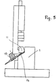
- Fig. 13 to 15 showing the wooden sill 2 from the outlet side of the moulder 2, the separation of a glazing bar 11 from the wooden sill 2 will be described. It is processed as it passes through the molding machine 1 in a known manner on all four sides. With the sitting on the right spindle 5 tool 12, which is rotatable about the axis 13, the right longitudinal side of the wood sill 2 is processed. In this case, the right longitudinal side 14 is processed as an example, so that near the top of a projecting web 15 stops.
- the tool 16 seated on it which is rotatable about a horizontal axis lying perpendicular to the transporting direction 4, inserts into the upper side 18 a section running in the longitudinal direction of the wooden skirt 2 .
- running profiling introduced.
- the tool 16 is designed or profiled in such a way that the glass strip 11 to be separated out has the required outer contour in this area.
- this profiling can be divided into the two upper spindles 7, 8, for example, can already be performed with the upper spindle 7 a saw cut, which is only nachprofiliert with the spindle 8. Since the wooden body is still very solid in the area of the upper spindles, a very good surface quality is achieved for this finished profiling.
- the pages processed by the upper tools are the later visible sides in the installed state of the glass strip 11.
- the usual today cutting raw glass strips takes place in that already on the right spindle a horizontal saw cut on the width of the raw glass strip and the bar already on the upper spindle or separated by using a separate glass bead saw from above.
- a high-quality machining with the upper tool is not possible because the bar with the previously introduced horizontal saw cut with no longer sufficient stability is associated with the wooden body.
- the glass strip can be excited during processing, for example, to vibrations.
- the glass strip 11 is completely separated from the wood skirt 2.
- the axis of rotation 19 of the glass bead saw 10 is an example at an angle of about 65 ° to the vertical.
- the glass bead saw 10 and the tool sitting thereon are designed so that with her the glass strip 11 processed at the bottom and at the same time is completely separated from the wood sill 2, wherein the glass strip 11 receives the required final profile.
- the glass bead saw 10 may have different training. In the exemplary embodiment, it is composed of a saw blade 10a and a frusto-conical milling tool 10b, which may be a chipper, for example.
- FIGS. 13 and 14 is indicated by dashed lines the end profile of the glass strip 11 after the separation of the glass strip 11.
- Fig. 15 is an exemplary end profile of the wood sill 2 shown with dashed lines. How out Fig. 15 it can be seen, the glass bead saw 10 is formed so that it has a distance from the end profile 20 of the wood sill 2. As a result, there is still sufficient material available to produce the end profile with a corresponding tool on this right long side of the wooden skirt 2. This is advantageously achieved in that the separating cut is made obliquely to the horizontal plane. This is the case when the axis of rotation 19 as described above is at an angle to the vertical.
- the glass strip 11 is cut out with the required finished Lssensprofiltechnik of the wood sill 2 in a single pass of the wood sill 2.
- the glass strip 11 can be manufactured inexpensively.
- Fig. 16 shows by way of example how with the remaining after the separation of the glazing bar 11 and finished in a further processing step part of the wooden frame 2 and the glass strip 11, a window sash can be produced.
- Fig. 16 shows a part of the lower frame part of the window sash with a part of the wooden skirt 2, on which the edge of a window pane 21 rests. It is supported in the edge region on a support surface 22 of the wooden skirt.
- the window pane 21 is secured by the glazing bar 11, which engages with the protruding web 15 in a recess 23 of the wooden skirt 2. This overlap makes it possible to compensate for length tolerances of the glazing bead and window sash without this becoming visually apparent. This is called a rebated glazing bead.
- the window pane 21 is sealed by two seals 24, 25, which are introduced between the wooden skirt 2 and the glass strip 11.
- the wooden skirt 2 and the glazing bead 11 are provided on their sides facing the window pane 21 with corresponding oblique surfaces 26, 27.
- the inclined surface 27 of the glass strip 11 is the surface which is produced during the separation by the glass bead saw 10 as a result of lying at an angle of rotation.
- the glazing bead 11 Since in the molding machine 1 the glazing bead 11 is separated from the wooden scant 2 in the manner described, out of the spout 28 (FIG. Fig. 1 ) of the molding machine 1, the finished profiled glazing bead 11 and the remaining part of the pre-profiled wooden skirt 2 from.
- the wooden skirt 2 reaches a transport device 29, which is advantageously an endlessly circulating conveyor belt. With him, the wood sill 2 further processing is supplied or, for example, transported to a (not shown) collection point in which the wooden shells 2 are stored for further use.
- a clipboard 30 is provided, on which the glazing beads 11 are deposited.
- two gripper units 31, 32 are provided.
- the gripper unit 31 (FIG. Fig. 4 ) is movable along a rail 33 by means of a carriage 34 in the X direction.
- a drive motor 35 is provided on the carriage 34.
- a carrier 36 is adjustable perpendicular to the X direction in the Z direction. He has two clamping elements 37, 38, with which the glass strip 11 can be clamped ( Fig. 7 ).
- the carrier 36 can be connected via a motor 39 (FIG. Fig. 4 ) are driven.
- the lower clamping element 38 is a support strip, which is rigidly connected to the carrier 36 and on which the glass strip 11 rests in the clamping position.
- the support bar has an upright bearing surface 88, on which the glass strip 11 rests laterally in the clamping position.
- the upper clamping element 37 is adjustable in the Z direction.
- the clamping element 37 is seated on two guide elements 40, which can be moved by means of a drive unit 41 in the Z direction.
- the drive unit 41 is seated on a boom 42 of the carrier 36.
- the drive of the drive unit 41 is preferably a pneumatic cylinder, not shown.
- the gripper unit 31 forms a 2-axis gripper, which can be moved in the X and Z directions.
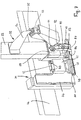
- the gripper unit 32 forms a 3-axis gripper, which can be moved in the X, Y and Z directions.
- the gripper unit 32 has a carriage 43 which is movable along a rail 44 in the X direction. It sits with its two ends in the Y-direction extending cross members 45, 46, along which the rail 44 can be moved in the Y direction.
- the cross members 45, 46 sit on the upper ends of columns 47 to 50, which stand up on the ground.
- the cross members 45, 46 and columns 47 to 51 are components of a machine frame.
- the rail 33 is attached, along which the gripper unit 31 can be moved in the X direction.
- the rail 33 is located with a such a distance below the cross members 45, 46, that the gripper unit 31 does not come into collision with the cross members when moving in the X direction.
- a drive 51 is provided. Slidable in the Z direction, a vertical carrier 52 is mounted on the carriage 43, which carries two clamping elements 53, 54 at the lower end.
- the lower clamping element 54 is formed as a support bar, on which the glass strip 11 rests in the transport position.
- the support bar 54 also has an upright abutment surface 83 (FIG. Fig. 9 ), on which the glass strip 11 rests laterally in the clamping position.
- the upper clamping element 53 can be adjusted by means of a drive unit 55 in the Z direction.
- the drive unit 55 with the associated guides is designed similarly to the drive unit 41 with the guides 40.
- the gripper unit 32 is provided with a further clamping element 89, which is provided on a pivot arm 90. It is pivotally mounted on the carrier 52 about a horizontal axis 91 extending in the X-direction. In the area between the pivot axis 91 and the clamping element 89 engages the pivot arm 90, a piston rod 92 of a drive unit 93 which is pivotally mounted at the free end of a support arm 94 about a horizontal axis 95 lying in the X direction. The support arm 94 projects transversely from the support 52 to which it is attached. With the clamping element 89, the glass strip 11 can be clamped on the left side. All clamping elements 53, 54, 89 are approximately at the same height, based on the clamped glass strip eleventh
- the gripper unit 32 can be moved along the rail 44 in the X direction.
- the rail 44 in turn can be moved in the Y direction along the mutually parallel cross members 45, 46.
- the carrier 52 with the clamping elements 53, 54, 89 can be moved in the Z direction.
- the clipboard 30 In the area between the columns 47 to 50 is the clipboard 30, on which the glass strips 11 are stored or stored.
- the clipboard 30 is height adjustable in the Z direction.
- the clipboard 30 can be mounted adjustable in height, for example, on two or more of the columns 47 to 50.
- the clipboard 30 in the X direction extending storage compartments 56, in which the glass strips 11 are stored.
- the storage compartments 56 may be formed, for example, by a correspondingly shaped sheet metal. So that the gripper unit 32 can reliably deposit the glazing beads 11 in the storage compartments 56, adjacent storage compartments are located next to one another at a distance in the X direction. In this area, the gripper unit 32 can retract with the clamping elements 53, 54, 89 in order to be able to deposit the respective glass strip 11.
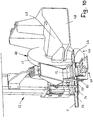
- a left miter saw 57 or processing unit and opposite in the region of the cross member 46 on the pillar 49 a right miter saw 58 is provided on the column 50.
- the left miter saw 57 ( Fig. 9 ) has an about an axis transverse to the X direction rotatable circular Zerspaner 59, with which the glass strip 11 can be machined at one end miter.
- the use of a chipper 59 instead of a circular saw blade has the advantage that miter cuts are not produced.
- the chipper 59 is located in a protective hood 60.
- the circular chipper 59 sits on a shaft driven by a drive unit 61.
- the drive unit 61 is mounted on a carrier 62, which is held on the cross member 45.
- a clamping station 63 In the area in front of the miter saw 57 is a clamping station 63, which has a clamping element 64 which is adjustable in the Y direction, and a clamping element 71 from above.
- the clamping station 63 with the clamping elements 64, 71 is located, seen in the transport direction 4 of the timber frame 2 through the molding machine 1, on the left side of the glass bead and before Miter saw 57.
- a further clamping station 84 is provided which has two clamping elements 85,86. With the clamping element 85, the glass strip 11 is clamped on the left side. The clamping element 86 engages over the glass strip 11 and clamps it from above.
- the right miter saw 58 ( Fig. 10 ) has a drive unit 65 with which a saw blade 66 can be rotatably driven.
- the saw blade 66 is located below a protective hood 67.
- the drive unit 65 is mounted on a carrier 68, which is fastened to the pillar 49.
- the axis of rotation of the miter saw 58 is again oblique to the X direction, but opposite to the axis of the opposite left miter saw 57 opposite.
- a clamping station 69 is likewise provided, which has at least one clamping element 70 which is adjustable in the Y direction for the lateral clamping of the glass strip 11. With it the glass strip is clamped laterally both before and after the saw. With the clamping element 72 in front of the miter saw 58, the glass strip 11 is clamped from above.
- the clamping stations of the two miter saws 57, 58 are suitably arranged fixed system. The mounting of the clamping stations 63, 69 is in Fig. 9 and 10 not shown in full for the sake of clarity.
- the glass strips 11 deposited on the clipboard 30 are removed by means of a slide 73 (FIG. Fig. 3 ) is supplied to a fan carriage 74, the above and juxtaposed tubular receptacles 75 for the glazing beads 11 has.
- the slider 73 is formed so that it can engage in the storage compartments 56 and rests on them, so that it can reliably move the therein glass strips in the receptacles 75 of the fan tray 74.
- the number of located on the clipboard 30 storage compartments 56 in the Y direction corresponds to the corresponding number of receptacles 75 of the fan tray 74 in a plane. As in Fig.
- the slider 73 extends in the Y direction and is displaceable at both ends along each of an X-directionally extending rail 76, 77.
- the slider 73 can be driven, for example, by means of belts 78 which are located on both sides of the rails 76, 77 such that the slider 73 is moved in the direction of the arrow 79 (FIG. Fig. 3 ) can be moved to push away the glazing beads 11 in the receptacles 75 as well as in the opposite direction. Since the clipboard 30 is height-adjustable in the Z-direction, it can be positioned relative to the compartment carriage 74 so that each floor of the compartmentalized carriage 74 can be filled with the glazing beads 11.
- the compartment car 74 is movable so that it can be driven away when sufficiently filled to remove the glazing beads 11 for further use.
- the compartment cart 74 is thus placed between the columns 47, 50 (FIG. Fig.1 ) moved up to the clipboard 30 and optionally fixed that the glazing beads 11 can be easily moved from the storage compartments 56 into the receptacles 75.
- a chute 80 ( Fig. 2 ), in the Fig. 1 for the sake of clarity is not shown. It extends between the columns 47, 48 obliquely backwards and downwards and serves to transport the raw glass strips arising during the machining process into a rough-bar cart 81.
- the Rohologicalnwagen 81 is also mobile.
- the wood trim 2 is processed on its four sides in the manner described and the glass strip 11 separated and simultaneously profiled.
- the profiled wooden skirt 2 and the profiled glass strip 11 emerge from the outlet 28 of the molding machine.
- the glazing bead 11 is fed in a manner to be described with the two gripper units 31, 32 to the miter saws 57, 58 to the miter cuts, if necessary, perform.
- the finished sawn glazing beads 11 are stored defined on the clipboard 30. With the slider 73, the glazing beads 11 are then pushed into the receptacles 75 of the fan tray 14.
- the miter saws 57, 58 may be arranged at a fixed angle, preferably of 45 °, obliquely to the longitudinal axis of the glass strip 11. It is advantageous, however, if the miter saws 57, 58 are set in different inclinations. In this case, the miter saws 57, 58 are pivotable about a vertical axis. During the sawing process, the glazing beads 11 are reliably clamped so that a clean miter cut can be made.
- the glazing bead 1 When passing the wooden beam 2 through the molding machine 1, the glazing bead 1 is separated from the wooden scant 2 by the tool 10 seated on the last spindle.
- the axis of rotation 19 of this glass bead saw 10 is arranged obliquely ( Fig. 4 . 5 . 12 and 15 ).
- the glass bead saw 10 has her downstream in the direction of passage a riving knife 96, which additionally forms a support and with which the glass strip 11 can be separated and guided cleanly out of the wood sill 2.
- a pressure roller, not shown, directly after the glass bead saw can if necessary press the glass strip 11 on this edition, so that the end of the glass strip at the time to which the Glazing bead is completely separated from the wooden body, safely guided and held.
- the gripper unit 31 is positioned at the outlet 28 of the molding machine 1 so that its clamping elements 37, 38 engage over the glass strip at the top and bottom and then can tension.
- the machine feed is taken over by the drive of the gripper unit 31 in the X direction.
- a control (not shown) is provided which synchronizes the transport speed of the gripper unit 31 with the feed speed of the molding machine.
- the clamping elements 37, 38 grasp the glass strip 11 at a distance from its front end in the feed direction, by virtue of the upper clamping element driving downwards, whereby the glass strip is clamped at the top and bottom.
- the distance from this front Glasologicalnende is for example about 120 to 150 mm.
- the shortest glazing bead may be 380 mm long and the longest glazing bead may be about 3000 mm long.
- the gripper unit 31 continues along the rail 33 in the X direction until the glazing bead 11 has completely emerged from the molding machine 1. Subsequently, the carrier 36 is moved with the clamping elements 37, 38 in the Z direction by a predetermined amount in a transfer position. In this transfer position, the glass strip 11 is taken over by the gripper unit 32.
- This gripper unit is arranged so that it lies in the region between the gripper unit 31 and the molding machine 1 directly next to the gripper unit 31. In this transfer position, the gripper unit 32 can bring by appropriate method in the X, Y and Z directions. Fig.
- FIG. 7 shows this transfer position, in which the two gripper units 31, 32 are arranged close to each other.
- the gripper unit 32 is initially in the X direction, then in the Y direction and finally in the Z direction.
- the gripper unit 32 is positioned so that the clamping elements 53, 54, 89 can receive the glass strip 11 immediately adjacent to the clamping elements 37, 38 of the gripper unit 31.
- With the clamping elements 53, 54, 89 is then in Fig. 7 clamped to the right of the gripper unit 31 lying part of the glass strip 11. In this transfer position, the glass strip 11 is thus clamped over a short period of time simultaneously by the clamping elements 37, 38 and 53, 54, 89 of the two gripper units 31, 32.
- the gripper unit 32 As soon as the gripper unit 32 has clamped the glass strip 11 in the transfer position, the clamping is released by the gripper unit 31. Subsequently, the gripper unit 32 is moved in the Y direction by moving the carriage 44 to the front, so that the glass strip 11 comes out of the clamping elements 37, 38 of the gripper unit 31. Subsequently, the carrier 52 of the gripper unit 32 with the clamped glass strip 11 in the Z direction can be moved upward on the gripper unit 31 and in the Y direction to the rear so far that the gripper unit 31 can drive back to the outlet 28 of the molding machine 1 ,
- the gripper unit 32 is moved on to transport the clamped glass strip 31 to the miter saws 57, 58. During miter sawing, the gripper unit 31 can pick up the next glazing bead 11 and bring it to the transfer position in the manner described.
- the glass strip 11 is first transported in the direction of the left miter saw 57 in the X direction.
- the clamping stations 63, 84 are open.
- a sensor (not shown) is provided with which the front end of the glass strip 11, which is in the transport direction, is detected.
- the sensor gives a corresponding signal, whereby the exact axial position of the glazing bead in the plant and with respect the gripper unit 32 is known to position the glazing bead 11 by means of the gripper unit 32.
- the glazing bar is clamped in the clamping station 63.
- the clamping element 64 of the clamping station 63 are pressed laterally and the clamping element 71 from above against the glass strip 11. In the area after the clamping station 63, the miter cut is performed.
- the clamping of the gripper unit 32 is depressurized. As a result, between the clamping elements 53, 54, 89 and the glass strip 11 forms a small air gap, which is for example only about 1/10 to 3/10 mm.
- the gripper unit 32 travels in the X direction in the direction of the right end of the glass strip 11. At a distance (for example about 120 to 150 mm) from this end, the gripper unit 32 clamps the glass strip 11. The clamping in the area of the clamping station 63 can now be released.
- the gripper unit 32 transports the clamped glass strip 11 in the X direction to the right miter saw 58 in order to perform a miter cut with it on the right side of the glass strip 11. Since the clamping takes place at a small distance from the right end of the glazing bead, the gripper unit 32 can accurately insert the glazing bead 11 in the X direction into the two clamping stations 69 in front of and behind the miter saw 58.
- the clamping elements 70, 72 of the clamping stations 69 clamp the glass strip 11 laterally and from above.
- the miter cut is made between the two clamping stations 69.
- the glass strip 11 is replaced by the exact part length.
- the clamping of the gripper unit 32 is depressurized, so that the described small air gap between the clamping elements 53, 54, 89 and the glass strip 11 is formed. As a result, the gripper unit 32 can travel back along the glass strip 11 to approximately half of its length. There then clamp the clamping elements 53, 54, 89, the glass strip 11. After the miter cut the clamping of the clamping stations 69 is released. The gripper unit 32 is then moved so far in the X direction that the glass strip 11 is released from the clamping stations 69. Then, the glass strip 11 can be stored with the gripper unit 32 in one of the storage compartments 56 of the clipboard 30 controlled.
- the gripper unit 32 can retract with its lower clamping element 54 in the intermediate region between adjacent storage compartments 56, so that the glass strips 11 can be stored reliably. Since the glazing beads 11 have been picked up by the gripper unit 32 at half the length, they lie in the clipboard 30 in such a way that they bridge the gap between adjacent, axially aligned storage compartments 56.
- the clipboard 30 has a defined number of trays 56 whose position is recorded in a controller. Therefore, the location of each glazing bar 11 in the clipboard 30 is accurately determined.
- the stored in the clipboard 30 glazing beads 11 are then pushed in the manner described with the slider 73 in the receptacles 75 of the fan tray 74.
- the clipboard 30 is moved in the Z direction so that the glazing beads 11 can be pushed into the desired plane of the receptacles 75.
- the glazing beads 11 With the slider 73, the glazing beads 11 are inserted so that they, as in Fig. 3 represented, still slightly protruding from the receptacles 75.
- the glazing beads can be easily removed from the corresponding receptacles 75 during the production of the window sashes.
- the position of the individual glazing beads 11 in the compartment trolley 74 is detected by the control, so that the matching wooden edges 2 and glazing beads 11 are used in the production of window casements.
- window sashes which are subdivided by, for example, a rung extending between opposite sides of the sash.
- two glazing beads are required for these casement sides, which extend from the rung to the adjacent casement side.
- the gripper unit 31 is first moved in synchronism with the feed of the molding machine 1 in the X direction and then completely pulled out of the molding machine 1. Subsequently, the gripper unit 31 is moved in the Z direction up to the transfer position.
- the gripper unit 32 moves in the X direction along the rail 44, which is then moved in the Y direction on the cross members 45, 46 so far that the gripper unit 32 is adjacent to the gripper unit 31. Subsequently, the carrier 52 is moved so far in the Z direction that the glass strip 11 can be clamped with the gripper unit 32. With the clamping element 89, the glass strip 11 against the upward contact surface 83 (FIG. Fig. 9 ) of the clamping element 54. The upper clamping element 53 of the gripper unit 32 clamps the glass strip 11 from above.
- the clamping of the gripper unit 32 is depressurized. This results in a small air gap of about 1/10 to 3/10 mm between the clamping elements 53, 54, 89 and the glass strip 11, which is fixed on four sides between the clamping elements 53, 54, 89 and the contact surface 83.
- the upper terminal strip 53, the lateral terminal block 89, the lower terminal block 54 and the contact surface 83 form a channel in which the glass strip 11 properly aligned, but a method of gripper unit in the X direction is possible.
- the gripper unit is now moved in the X direction along the glazing bead 11 into a position in which the glazing bar is cut into two glass glazing parts with the left miter saw 57 and at the same time the required miter cut can be made on the right glazing bead part. That is, in the axial clamping position, the length of the left section with considered. Once this position is reached, the glass strip 11 is clamped by the gripper unit 32. Now, the clamping can be canceled by the gripper unit 31. As described above, the gripper unit 32 is moved so that the gripper unit 31 along the rail 44 in the direction of the outlet 28 of the molding machine 1 can be moved to take over the next glazing bead 11 there.
- the gripper unit 32 is then moved in the manner described to the left miter saw 57, so that the glass strip 11 clamped by it passes in the process in the X direction in the clamping stations 63, 84 located on the left miter saw 57.
- the arranged in the region of the terminal stations sensor detects the left end of the glass strip 11.
- the glass strip 11 defined in the X direction can be moved so far that with the miter saw 57, the first miter cut can be performed.
- the glass strip 11 is divided into two parts, with the miter cut of the resulting right glass bead part is now mitred at its left end.
- the glazing bead 11 is clamped in the clamping stations 63, 84 so that a clean miter cut can be made.
- the clamping of the gripper unit 32 is depressurized, resulting in the small air gap of about 1/10 to 3/10 mm between the clamping elements and the glass strip.
- the gripper unit 32 can now be moved along the right glass bead part in the X direction so far that the clamping elements as described have a defined distance from the right end of the right glass bead part. Now this right glass bead part is stretched by the gripper unit 32 and lifted the clamping in the clamping station 63. The left section remains tensioned in the clamping station 84.
- the gripper unit 32 can now transport the right glazing bead part to the right miter saw 58 in the X direction.
- the clamping stations 69 are open. After clamping by the clamping stations 69, the right miter cut is made on this right glass bead part. He has thus, since at both its ends with the two miter saws 57, 58, the miter cuts have been executed, its exact part length.
- the clamping of the gripper unit 32 is depressurized so that it can be moved along the right glass bead part so far in the X direction until it is about halfway along this right glass bead part. Now this right glass bead part can be tensioned by the gripper unit 32. Then, the clamping of the right Glasolinnmaschines is removed in the clamping stations 69 by the clamping elements 70, 72 are moved away laterally and upwards. With the gripper unit 32 now the right glass bead part can be stored in the manner described in the clipboard 30.
- the remaining part of the miter cut at the miter saw 58 falls over the channel described in the waste container.
- the left glass bead part is still clamped in the provided behind the left miter saw 57 clamping station 84 (FIG. Fig. 9 ). Their two clamping elements 85, 86 clamp the left glazing bead part from above and from the left side.
- the entire clamping station 84 is movable in the direction of arrow 87 in the Y direction.
- the clamping station 84 is moved so far in the direction of the arrow 87 that the left glazing bead part gets a sufficient distance from the miter saw 57.
- the clamping elements 53, 54, 89 of the gripper unit 32 can take over the left glazing bead part. With the gripper unit 32, this left glazing bead part is transported to the miter saws 57, 58 to make the miter cuts at both ends.
- the glass strip 11 is provided only at one end with a miter cut. Do you want the miter? the left side of the glass strip 11 are made, the process is identical to the previously described process with miter cuts on both sides.
- the glass strip is transported in the X direction by the gripper unit 32 until the sensor in the region of the left miter saw 57 detects the last beginning, whereby the exact axial Position in the plant is known. Since the glass strip is always clamped either in one of the clamping units or the gripper unit 32 in the further operations, the position position is no longer lost.
- the glass strip can always be exactly positioned over the X axis of the gripper unit 32 during further processing and handling.
- the glass strip is then clamped in the clamping station 63 and performed with the miter saw 57 at the left end of the glass strip 11 of the miter cut.
- the clamping of the gripper unit 32 is depressurized, so that the gripper unit 32 can be moved approximately in half the length of the glass strip 11.
- the glass strip 11 is clamped and stored by means of the gripper unit 32 in the clipboard 30.
- the process is also identical to the previously described process with miter cuts on both sides with the difference that at the left end no miter cut is performed. Since the optical sensor for accurate position detection is provided only on the left miter saw, this process is necessary. If the right-hand miter saw also has an optical sensor that then detects the right-hand beginning of the glass strip, the glass strip can also be fed immediately to the right-hand miter saw. The transfer of the gripper unit 31 to the gripper unit 32 is then carried out so that the gripper unit 32 receives the glass strip in the X direction near the right end and clamps. The further procedure is as described. Depending on the desire and further handling, the one-sided mitred glass strips are stored in the clipboard 30 or placed in the Rohologicalnwagen 81.
- the glass strip 11 is detected in the manner described at the outlet 28 of the molding machine 1 by the gripper unit 31 and transported to the transfer position, in which the glass strip 11 is transferred in the manner described to the gripper unit 32. It transports the glass strip 11 into the area above the chute 80 (FIG. Fig. 2 ). The clamping elements of the gripper unit 32 are then opened, so that the glass strip 11 passes through the chute 80 in the Rohologicalnwagen 81.
- Such glazing beads are not necessarily profiled in the moulder, but only planed, for example. You fall for example, if from the wooden shells 2 no window sash, but window frames are to be made. For window frames, glazing beads are not required. These pre-machined glass strips can be finished in a later processing step and used for the production of window sashes.
- the glazing beads 11 are transported by means of the described gripper devices 31, 32 to the left and / or the right miter saw 57, 58, depending on the further processing task, on which the respective miter cut is made on the glazing bead 11.
- clamping stations are provided in front of and behind the saw, so that the glass strip 11 is clamped or clamped properly during the miter cut. This allows the miter cut to be made accurately.
- the glass strip 11 is always accurately introduced into the clamping stations by the gripper unit 32 is positioned in the region of that end at which the miter cut is to be performed. Especially with long glazing beads 11 is thereby ensuring that the end to be mitered is fed exactly to the clamping stations. Since the unpressurized jaws form the channel described, in which the glass strip has little play, the gripper unit 32 can be moved along the glass strip in the different positions with respect to the glass strip 11, whereby it is achieved that the glass strip, especially if it is longer is held straight or straightened so that a reliable clamping, processing and safe transport of the glass strip 11 is guaranteed in the system.
- the system thus makes it possible to profile glass strips in a moulder on the longitudinal sides in a fully automated process sequence and to cut them out of a wooden skirt and, if required, to execute the miter cuts using downstream manipulation and processing devices so that the glass strip is ready for installation ,
- the transfer always takes place in such a way that the gripper unit 32 first moves directly next to the gripper unit 31 and clamps the glass strip. If the glass strip 11 must be detected at a different location, the gripper unit 31 is depressurized and then moved in the X direction. Since the glazing beads 11 can sag outside of the clamping and can also be rotated by residual stresses, it is not possible to grasp the gripper unit 32 at a distance from the gripper unit 31.
- gripper units 31, 32 other manipulators can also be used, for example robots.
- robots Depending on the required throughput or required quantity of power, only one gripper unit 32 or robot can be used, which removes the glazing beads both of the molding machine and supplies it to the glass bead saws.
- two gripper units 31 are provided one behind the other in the X direction, of which the first clamps the glazing bead 11 on leaving the moulder 1 as described at the outlet end after the speed has been synchronized.
- the second gripper unit which is provided in the direction of passage between the first and the outlet side of the molding machine, stops until the glass strip 11 is almost severed, then synchronized with the feed rate and then clamps the glass strip on the outlet side rear, so right end. This ensures that the glass strip 11 is optimally held at the time of complete separation.
Description
Die Erfindung betrifft eine Anlage zur Herstellung oder Herstellung und Behandlung von Glasleisten nach dem Oberbegriff des Anspruches 1 sowie ein Verfahren unter Verwendung einer solchen Anlage nach dem Oberbegriff des Anspruches 12. Eine solche Anlage und ein solches Verfahren ist aus der
Der Erfindung liegt die Aufgabe zugrunde, die gattungsgemäße Anlage und das gattungsgemäße Verfahren so auszubilden, dass Glasleisten aus einem Werkstück einfach hergestellt, ausgetrennt und weiterbehandelt werden können.The invention has the object of providing the generic system and the generic method in such a way that glazing beads can be easily made from a workpiece, separated and treated further.
Diese Aufgabe wird bei der gattungsgemäßen Anlage erfindungsgemäß mit den Merkmalen des Anspruches 1 und beim gattungsgemäßen Verfahren erfindungsgemäß mit den Merkmalen des Anspruches 12 gelöst.This object is achieved in the generic system according to the invention with the features of claim 1 and in the generic method according to the invention with the features of
Vorteilhaft ist die Bearbeitungsmaschine eine Kehlmaschine, mit der in einem Durchlauf die Werkstücke an allen vier Seiten bearbeitet werden können. Dabei wird gleichzeitig auch die Glasleiste aus dem Werkstück herausgetrennt. Erfindungsgemäß sitzt das eine Werkzeug auf einer horizontalen Spindel, die sich im Transportweg des Werkstückes durch die Bearbeitungsmaschine im Bereich oberhalb des Werkstückes befindet. Mit diesem Werkzeug kann beim Durchlauf des Werkstückes in der Oberseite ein erster Schnitt erzeugt werden, mit dem die Glasleiste teilweise vom Werkstück getrennt wird. Bevorzugt hinter diesem Werkzeug, in Vorschubrichtung des Werkstückes durch die Bearbeitungsmaschine gesehen, befindet sich das andere Werkzeug, das erfindungsgemäß eine schräg zur Transportrichtung des Werkstückes liegende Drehachse aufweist. Da die beiden Werkzeuge Abstand in Transportrichtung des Werkstückes hintereinander liegen, können die erforderlichen Schnitte im Werkstück problemlos und genau vorgesehen werden.Advantageously, the processing machine is a molding machine with which the workpieces can be processed on all four sides in one pass. At the same time, the glass strip is also cut out of the workpiece. According to the invention, the one tool sits on a horizontal spindle, which is located in the transport path of the workpiece through the processing machine in the area above the workpiece. With this tool, a first cut can be produced during the passage of the workpiece in the upper side, with which the glass strip is partially separated from the workpiece. Preferably behind this tool, seen in the feed direction of the workpiece through the processing machine, there is the other tool, which according to the invention has a rotational axis lying obliquely to the transport direction of the workpiece. Since the two tools are spaced one behind the other in the transport direction of the workpiece, the required cuts in the workpiece can be provided easily and accurately.
Das andere Werkzeug mit der schräg liegenden Drehachse ist erfindungsgemäß aus einem Sägeblatt und einem kegelstumpfförmigem Fräswerkzeug zusammengesetzt. Dieses bildet einen Zerspaner, mit dem die Glasleiste an deren Unterseite bearbeitet werden kann.The other tool with the oblique axis of rotation according to the invention is composed of a saw blade and a frusto-conical milling tool. This forms a chipper, with which the glass strip can be processed on the underside.
Mit dem scheibenförmigen Sägeblatt wird der erforderliche Trennschnitt im Werkstück zum Abtrennen der Glasleiste hergestellt. Erfindungsgemäß treten die abgetrennte Glasleiste und der restliche Teil des Werkstückes gleichzeitig aus dem Auslauf der Bearbeitungsmaschine aus. Vorteilhaft wird dann lediglich die Glasleiste erfasst und weiterbehandelt, während der restliche Teil des Werkstückes über eine Transporteinrichtung für eine weitere Bearbeitung weitertransportiert wird.With the disc-shaped saw blade of the required separating cut in the workpiece for separating the glass strip is made. According to the invention, the severed glass strip and the remaining part of the workpiece exit simultaneously from the outlet of the processing machine. Advantageously, then only the glass bead is detected and further treated, while the remaining part of the workpiece is transported by a transport device for further processing.
Bei einer weiteren Ausgestaltung der erfindungsgemäßen Anlage ist der Bearbeitungsmaschine wenigstens eine Ablageeinrichtung nachgeschaltet. Sie ist mit wenigstens einer, vorzugsweise mit zwei Greifereinheiten versehen, mit denen die Glasleisten der Bearbeitungsmaschine entnommen und auf wenigstens einer Ablage abgelegt werden können.In a further embodiment of the system according to the invention, the processing machine is followed by at least one depositing device. It is provided with at least one, preferably with two gripper units with which the glass strips of the processing machine can be removed and stored on at least one tray.
Bei einer bevorzugten Ausführungsform ist die eine Greifereinheit eine 2-Achs-Greifereinheit, mit der die Glasleiste in zwei zueinander senkrechten Richtungen transportiert werden kann. Diese Greifereinheit übernimmt vorteilhaft die aus der Bearbeitungsmaschine austretende, fertig profilierte Glasleiste.In a preferred embodiment, the one gripper unit is a 2-axis gripper unit, with which the glass strip can be transported in two mutually perpendicular directions. This gripper unit takes advantage of emerging from the machine, finished profiled glass bead.
Bevorzugt ist die andere Greifereinheit eine 3-Achs-Greifereinheit, die die Glasleiste in drei zueinander senkrechten Richtungen transportieren kann.Preferably, the other gripper unit is a 3-axis gripper unit, which can transport the glass strip in three mutually perpendicular directions.
Die beiden Greifereinheiten sind bei einer bevorzugten Ausgestaltung in eine Übergabeposition verstellbar, in welcher die eine Greifereinheit die Glasleiste der anderen Greifereinheit übergibt. Die eine Greifereinheit übernimmt die Glasleiste beim Austritt aus der Bearbeitungsmaschine und transportiert sie in die Übergabeposition. Die zweite Greifereinheit übernimmt die Glasleiste. Sobald die Übergabe erfolgt ist, kann die erste Greifereinheit wieder zurück zur Bearbeitungsmaschine verfahren werden, um die nächste Glasleiste aufzunehmen. Während dieser Zeit kann die Glasleiste mittels der zweiten Greifereinheit einer weiteren Bearbeitung und/oder Behandlung zugeführt werden.The two gripper units are adjustable in a preferred embodiment in a transfer position, in which one gripper unit passes the glass strip of the other gripper unit. The one gripper unit takes over the glass strip when leaving the processing machine and transports it to the transfer position. The second gripper unit takes over the glazing bead. Once the transfer has taken place, the first gripper unit can return Move back to the processing machine to record the next glazing bead. During this time, the glass strip can be supplied by means of the second gripper unit of a further processing and / or treatment.
Die eine Greifereinheit erfasst vorteilhaft die Glasleiste am Auslauf der Bearbeitungsmaschine und transportiert sie in die Übergabeposition. Solange die Glasleiste noch nicht vollständig von dem Werkstück abgetrennt worden ist, wird die Verfahrgeschwindigkeit der ersten Greifereinheit mit der Vorschubgeschwindigkeit der Glasleiste in der Bearbeitungsmaschine synchronisiert. Sobald die Glasleiste vollständig abgetrennt worden ist und gegebenenfalls durch die erste Greifereinheit vollständig aus der Bearbeitungsmaschine herausgezogen worden ist, kann die Greifereinheit nunmehr unabhängig von der Vorschubgeschwindigkeit der Bearbeitungsmaschine die Glasleiste in die Übergabeposition transportieren.The one gripper unit advantageously detects the glass strip at the outlet of the processing machine and transports it to the transfer position. As long as the glass strip has not yet been completely separated from the workpiece, the traversing speed of the first gripper unit is synchronized with the feed rate of the glass strip in the processing machine. As soon as the glass strip has been completely separated off and has possibly been completely pulled out of the processing machine by the first gripper unit, the gripper unit can now transport the glass strip to the transfer position independently of the feed speed of the processing machine.
Die Anlage ist in bevorzugter Ausbildung mit wenigstens einer Gehrungssäge versehen, mit der an der Glasleiste, sofern erforderlich, ein Gehrungsschnitt erzeugt werden kann. Unter einer Gehrungssäge ist auch ein Zerspaner zu verstehen, mit dem an der Glasleiste eine Gehrung bearbeitet werden kann.The plant is provided in a preferred embodiment with at least one miter saw, with the glass bar, if necessary, a miter cut can be generated. A miter saw should also be understood as a chipper with which a miter can be machined on the glazing bead.
Bevorzugt weist die Anlage eine linke und eine rechte Gehrungssäge auf, so dass mit diesen beiden Gehrungssägen ein linker und ein rechter Gehrungsschnitt an der Glasleiste erzeugt werden kann.Preferably, the plant has a left and a right miter saw, so that with these two miter saws, a left and a right Miter cut can be generated on the glass strip.
Damit ein sauberer Gehrungsschnitt hergestellt werden kann, ist die Anlage in vorteilhafter Ausbildung vor der jeweiligen Gehrungssäge mit jeweils einer Klemmstation versehen. Die Glasleiste wird in den Klemmstationen für den Gehrungsschnitt eingespannt. Aufgrund der Einspannung der Glasleiste in diesen beiden Klemmstationen ergibt sich ein sauberer und exakter Gehrungsschnitt.In order for a clean miter cut can be made, the system is provided in an advantageous training before the respective miter saw, each with a clamping station. The glass strip is clamped in the clamping stations for the miter cut. Due to the clamping of the glazing bar in these two clamping stations results in a clean and accurate miter cut.
Bevorzugt wird die zweite Greifereinheit, mit der die Glasleiste der Gehrungssäge und den zugehörigen Klemmstationen zugeführt wird, vorteilhaft drucklos geschaltet. Dadurch ergibt sich ein geringer Luftspalt zwischen den Klemmelementen der zweiten Greifereinheit und der Glasleiste. Die zweite Greifereinheit kann dadurch längs der Glasleiste in X-Richtung verfahren werden, solange die Glasleiste in den Klemmstationen bei den Gehrungssägen eingespannt ist. So ist es möglich, dass die zweite Greifereinheit in der Zeit, in der beispielsweise mit der linken Gehrungssäge ein Gehrungsschnitt erzeugt wird, längs der Glasleiste in Richtung auf deren rechtes Ende verfahren wird, so dass die zweite Greifereinheit die Glasleiste in diesem Endbereich spannen kann, um die Glasleiste nach Erzeugung des Gehrungsschnitts mittels der linken Gehrungssäge zur rechten Gehrungssäge zu transportieren. Da die Einspannung der Glasleiste durch die zweite Greifereinheit nahe dem rechten Ende der Glasleiste erfolgt, lässt sich diese präzise in die Klemmstationen vor und hinter der rechten Gehrungssäge einführen.Preferably, the second gripper unit, with which the glazing bead of the miter saw and the associated clamping stations is supplied, advantageously switched unpressurized. This results in a small air gap between the clamping elements of the second gripper unit and the glass strip. The second gripper unit can thereby be moved along the glass strip in the X direction, as long as the glass strip is clamped in the clamping stations in the miter saws. Thus, it is possible that the second gripper unit is moved along the glass strip in the direction of its right end during the time in which, for example, a miter cut is produced with the left miter saw, so that the second gripper unit can clamp the glass strip in this end region, to transport the glazing bead to the right miter saw after creating the miter cut using the left miter saw. Since the clamping of the glazing bar by the second gripper unit takes place near the right end of the glazing bead, it can be precisely inserted into the clamping stations in front of and behind the right miter saw.
Vorteilhaft ist die Ablageeinrichtung mit Ablagefächern für die Glasleisten versehen, in denen sich die Glasleisten geordnet und genau ablegen lassen.Advantageously, the storage device is provided with storage compartments for the glazing beads, in which the glazing beads can be ordered and stored exactly.
Die Ablagefächer lassen sich in der Höhe in Z-Richtung verstellen.The storage compartments can be adjusted in height in Z-direction.
Die Anlage ist vorteilhaft mit wenigstens einem Schieber versehen, mit dem die in den Ablagefächern liegenden Glasleisten in Aufnahmen verschoben werden können.The system is advantageously provided with at least one slide, with which the lying in the storage compartments glass strips can be moved in recordings.
Die Aufnahmen sind vorteilhaft über- und nebeneinander angeordnet, so dass auf kleinem Raum eine große Zahl von Glasleisten aufgenommen werden kann. Da die Ablagefächer in der Höhe verstellbar sind, lassen sich die Glasleisten in die übereinander angeordneten Aufnahmen problemlos einschieben.The recordings are advantageously arranged above and next to one another, so that a large number of glass strips can be accommodated in a small space. Since the storage compartments are adjustable in height, the glass strips can be easily inserted into the superimposed receptacles.
Die Aufnahmen sind vorteilhaft an einem Transportwagen vorgesehen, der nach dem Befüllen der Aufnahmen weggefahren werden kann, damit die Glasleisten der weiteren Verwendung zur Verfügung gestellt werden, um beispielsweise Fensterflügel herzustellen.The recordings are advantageously provided on a trolley, which can be moved away after filling the recordings, so that the glazing beads are made available for further use, for example to produce window sashes.
Beim erfindungsgemäßen Verfahren wird die aus dem Auslauf der Bearbeitungsmaschine austretende Glasleiste von der Greifereinheit erfasst. Zu diesem Zeitpunkt ist die Glasleiste noch nicht vollständig von dem Werkstück abgetrennt worden. Darum wird die Greifereinheit, bevor sie das Ende der Glasleiste erfasst hat, synchron mit dem Vorschub der Bearbeitungsmaschine bewegt.In the method according to the invention, the glass strip emerging from the outlet of the processing machine is detected by the gripper unit. At this time, the glass bead has not yet been completely separated from the workpiece. Therefore, the gripper unit is moved synchronously with the feed of the processing machine before it has detected the end of the glass strip.
Sobald die Glasleiste von dem Werkstück vollständig abgetrennt und gegebenenfalls mit der Greifereinheit aus der Bearbeitungsmaschine herausgezogen worden ist, wird sie mittels dieser Greifereinheit Bearbeitungsaggregaten zugeführt, mit denen die Glasleiste bearbeitet werden kann.As soon as the glass strip has been completely separated from the workpiece and optionally pulled out of the processing machine with the gripper unit, it is fed by means of this gripper unit to processing units with which the glass strip can be processed.
Vorteilhaft sind die Bearbeitungsaggregate Gehrungssägen bzw. Zerspaner, mit denen die Glasleiste auf fertige Längen und auf Gehrung geschnitten wird.Advantageously, the processing units miter saws or chipper, with which the glass strip is cut to finished lengths and mitred.
Bei einer vorteilhaften Verfahrensführung transportiert die Greifereinheit die Glasleiste zu einer Gehrungssäge. Dabei wird die Glasleiste vor, bei Bedarf vor und hinter der Gehrungssäge eingespannt bzw. geklemmt, so dass ein sauberer Gehrungsschnitt durchgeführt werden kann. Solange der Gehrungsschnitt durchgeführt wird, wird die Klemmung der Greifereinheit drucklos geschaltet. Dadurch ergibt sich ein geringer Luftspalt zwischen den Klemmelementen dieser Greifereinheit und der Glasleiste. Dadurch kann die Greifereinheit längs der Glasleiste in Richtung auf das andere Glasleistenende verfahren werden. Dort kann die Greifereinheit die Glasleiste mit Abstand zu deren Ende wieder klemmen, so dass die Glasleiste nach Erzeugung des einen Gehrungsschnittes zur gegenüberliegenden Gehrungssäge transportiert werden kann, um nunmehr am anderen Ende den Gehrungsschnitt vorzunehmen.In an advantageous method guide, the gripper unit transports the glass strip to a miter saw. The glass strip is clamped in front of and behind the miter saw, if necessary, so that a clean miter cut can be made. As long as the miter cut is performed, the clamping of the gripper unit is depressurized. This results in a small air gap between the clamping elements of this gripper unit and the glass strip. As a result, the gripper unit can be moved along the glass strip in the direction of the other end of the glass bead. There, the gripper unit can clamp the glass strip at a distance from the end again, so that the glass strip after generating the one miter cut to the opposite miter saw can be transported to make the miter cut now at the other end.
Sobald der oder die erforderlichen Gehrungsschnitte erzeugt worden sind, wird die Greifereinheit vorteilhaft bei drucklos geschalteter Klemmung längs der Glasleiste etwa bis in deren halbe Länge verfahren. Dort wird die Glasleiste mit dieser Greifereinheit geklemmt. Anschließend kann die Klemmung vor der Gehrungssäge gelöst werden. Dann lässt sich die Glasleiste mit der Greifereinheit in den Ablagefächern ablegen.As soon as the required miter cuts have been produced, the gripper unit is advantageously moved downwards in the half-length along the glazing bead when the clamping is switched without pressure. There, the glass strip is clamped with this gripper unit. Then the clamp can be released in front of the miter saw. Then the glass strip with the gripper unit can be placed in the storage compartments.
Bei einer bevorzugten Ausbildung wird die Glasleiste mit der Greifereinheit in eine Übergabeposition transportiert. Hier wird die Glasleiste einer anderen Greifereinheit übergeben.In a preferred embodiment, the glass strip is transported with the gripper unit in a transfer position. Here, the glass strip is handed over to another gripper unit.
Der Anmeldungsgegenstand ergibt sich nicht nur aus dem Gegenstand der einzelnen Patentansprüche, sondern auch durch alle in den Zeichnungen und der Beschreibung offenbarten Angaben und Merkmale. Sie werden, auch wenn sie nicht Gegenstand der Ansprüche sind, als erfindungswesentlich beansprucht, soweit sie einzeln oder in Kombination gegenüber dem Stand der Technik neu sind.The subject of the application results not only from the subject matter of the individual claims, but also by all the information and features disclosed in the drawings and the description. They are, even if they are not the subject of the claims, claimed as essential to the invention, as far as they are new individually or in combination over the prior art.
Weitere Merkmale der Erfindung ergeben sich aus den weiteren Ansprüchen, der Beschreibung und den Zeichnungen.Further features of the invention will become apparent from the other claims, the description and the drawings.
Die Erfindung wird anhand eines in der Zeichnung dargestellten Ausführungsbeispieles näher erläutert. Es zeigen
- Fig. 1
- in perspektivischer Darstellung eine erfindungsgemäße Anlage zur Herstellung von Glasleisten,
- Fig. 2
- in perspektivischer Darstellung einen Rohleistenwagen sowie einen Fächerwagen der erfindungsgemäßen Anlage,
- Fig. 3
- in perspektivischer Darstellung den Fächerwagen gemäß
Fig. 2 , mit einer Zwischenablage und einer Abschiebeeinheit - Fig. 4
- in perspektivischer Darstellung eine Glasleistensäge der erfindungsgemäßen Anlage sowie eine erste Greifereinheit zum Ergreifen der mit der Glasleistensäge ausgesägten Glasleiste,
- Fig. 5
- in schematischer Darstellung und mit Sicht auf den Auslaufbereich der Bearbeitungsmaschine die Glasleistensäge gemäß
Fig. 4 , - Fig. 6
- den Auslaufbereich der Bearbeitungsmaschine mit der ersten Greifereinheit,
- Fig. 7
- in vergrößerter Darstellung eine Übergabeposition zweier Greifereinheiten, mit denen eine ausgetrennte Glasleiste übergeben wird,
- Fig. 8
- in vergrößerter Darstellung die beiden Greifereinheiten gemäß
Fig. 7 in der Übergabeposition, - Fig. 9
- in perspektivischer Darstellung ein linkes Gehrungsaggregat der erfindungsgemäßen Anlage,
- Fig. 10
- in perspektivischer Darstellung eine rechte Gehrungssäge der erfindungsgemäße Anlage,
- Fig. 11
- in vergrößerter Darstellung eine Zwischenablage der erfindungsgemäßen Anlage, in die mit einer Greifereinheit eine Glasleiste abgelegt wird,
- Fig. 12
- in schematischer Darstellung eine Kehlmaschine der erfindungsgemäßen Anlage,
- Fig. 13
bis 15 - jeweils unterschiedliche Verfahrensschritte beim Heraustrennen der Glasleiste aus einem Werkstück in Form einer Holzkantel,
- Fig. 16
- in schematischer Darstellung einen unteren Rand eines Fensterflügels mit eingesetzter Fensterscheibe.
- Fig. 1
- in a perspective view of a plant according to the invention for the production of glazing beads,
- Fig. 2
- in a perspective view a Rohleistenwagen and a compartment car of the system according to the invention,
- Fig. 3
- in a perspective view of the compartment car according to
Fig. 2 , with a clipboard and a deportation unit - Fig. 4
- a perspective view of a glass bead saw of the system according to the invention and a first gripper unit for gripping the glass bead sawn with the glass bead saw,
- Fig. 5
- in a schematic representation and with a view of the outlet region of the processing machine according to the glass bead saw
Fig. 4 . - Fig. 6
- the outlet region of the processing machine with the first gripper unit,
- Fig. 7
- in an enlarged view, a transfer position of two gripper units with which a separate glass strip is transferred,
- Fig. 8
- in an enlarged view of the two gripper units according to
Fig. 7 in the transfer position, - Fig. 9
- in a perspective view a left miter unit of the system according to the invention,
- Fig. 10
- in perspective view a right miter saw of the plant according to the invention,
- Fig. 11
- in an enlarged view, a clipboard of the system according to the invention, in which a glass strip is deposited with a gripper unit,
- Fig. 12
- a schematic representation of a molding machine of the plant according to the invention,
- Fig. 13 to 15
- different process steps when separating the glass strip from a workpiece in the form of a wooden skirt,
- Fig. 16
- a schematic representation of a lower edge of a window sash with inserted window.
Mit der Anlage werden aus Werkstücken, die nachfolgend als Holzkanteln bezeichnet werden, Glasleisten ausgesägt, sowie die Holzkanteln zur Weiterbearbeitung für Fensterflügel- und Fensterrahmenteile vorbearbeitet. Hierfür hat die Anlage eine Bearbeitungsmaschine 1, die vorteilhaft eine Kehlmaschine ist. In ihr werden die Holzkanteln beim Durchlauf bearbeitet und aus ihnen die Glasleiste herausgetrennt. Der grundsätzliche Aufbau der Kehlmaschine wird anhand von
Der linken Spindel 6 nachgeschaltet sind zwei mit Abstand hintereinander liegende obere horizontale Spindeln 7 und 8, die Werkzeuge tragen, mit denen die Oberseite der Holzkantel 2 bearbeitet werden kann.The left-
In Transportrichtung 4 mit Abstand hinter der oberen Spindel 8 ist die Kehlmaschine mit einer unteren horizontalen Spindel 9 versehen, mit deren Werkzeug die Unterseite der Holzkantel 2 bearbeitet werden kann. Schließlich ist die Kehlmaschine mit einer Glasleistensäge 10 versehen, mit der aus der Holzkantel 2 in noch zu beschreibender Weise eine Glasleiste herausgetrennt werden kann. Die Drehachse der Glasleistensäge 10 liegt schräg zur Vertikalen.In the transport direction 4 at a distance behind the upper spindle 8, the molding machine is provided with a lower horizontal spindle 9, with the tool, the underside of the
Anhand der
Schließlich wird beim weiteren Durchlauf der Holzkantel 2 durch die Kehlmaschine mit der Glasleistensäge 10 die Glasleiste 11 vollständig von der Holzkantel 2 getrennt. Die Drehachse 19 der Glasleistensäge 10 liegt beispielhaft unter einem Winkel von etwa 65° zur Vertikalen. Die Glasleistensäge 10 und das darauf sitzende Werkzeug sind so ausgebildet, dass mit ihr die Glasleiste 11 an der Unterseite bearbeitet und gleichzeitig vollständig von der Holzkantel 2 getrennt wird, wobei die Glasleiste 11 das erforderliche Endprofil erhält. Je nach Gestaltung der Glasleiste 11 kann die Glasleistensäge 10 unterschiedliche Ausbildung haben. Im Ausführungsbeispiel ist sie aus einem Sägeblatt 10a und einem kegelstumpfförmigem Fräswerkzeug 10b, das beispielsweise ein Zerspaner sein kann, zusammengesetzt.Finally, during the further passage of the
In den
Mit der beschriebenen Kehlmaschine wird bei einem einzigen Durchlauf der Holzkantel 2 die Glasleiste 11 mit der erforderlichen fertigen Längsprofilierung von der Holzkantel 2 herausgetrennt. Dadurch kann die Glasleiste 11 kostengünstig gefertigt werden.With the moulder described, the
Die Fensterscheibe 21 ist durch zwei Dichtungen 24, 25 abgedichtet, die zwischen der Holzkantel 2 und der Glasleiste 11 eingebracht werden. Zur Bildung entsprechender Aufnahmeräume für die Dichtungen 24, 25 sind die Holzkantel 2 und die Glasleiste 11 an ihren der Fensterscheibe 21 zugewandten Seiten mit entsprechenden Schrägflächen 26, 27 versehen. Die Schrägfläche 27 der Glasleiste 11 ist diejenige Fläche, die beim Auftrennen durch die Glasleistensäge 10 infolge der unter dem Winkel liegenden Drehachse hergestellt wird.The
Da in der Kehlmaschine 1 die Glasleiste 11 von der Holzkantel 2 in der beschriebenen Weise getrennt wird, treten aus dem Auslauf 28 (
Die Greifereinheit 31 (
Die Greifereinheit 31 bildet einen 2-Achsgreifer, der in X- und Z-Richtung verfahren werden kann.The
Die Greifereinheit 32 bildet einen 3-Achsgreifer, der in X-, Y- und Z-Richtung verfahren werden kann. Die Greifereinheit 32 hat einen Schlitten 43, der längs einer Schiene 44 in X-Richtung verfahrbar ist. Sie sitzt mit ihren beiden Enden auf in Y-Richtung sich erstreckenden Querträgern 45, 46, längs denen die Schiene 44 in Y-Richtung verfahren werden kann. Die Querträger 45, 46 sitzen auf den oberen Enden von Säulen 47 bis 50, die auf dem Untergrund aufstehen. Die Querträger 45, 46 und Säulen 47 bis 51 sind Bestandteile eines Maschinengestelles. An den beiden Säulen 49, 50 ist die Schiene 33 befestigt, längs welcher die Greifereinheit 31 in X-Richtung verfahren werden kann. Die Schiene 33 befindet sich mit einem solchen Abstand unterhalb der Querträger 45, 46, dass die Greifereinheit 31 beim Verfahren in X-Richtung nicht in Kollision mit den Querträgern gelangt.The
Zum Verfahren des Schlittens 43 längs der Schiene 44 ist ein Antrieb 51 vorgesehen. In Z-Richtung verschiebbar ist am Schlitten 43 ein vertikaler Träger 52 gelagert, der am unteren Ende zwei Klemmelemente 53, 54 trägt. Das untere Klemmelement 54 ist als Auflageleiste ausgebildet, auf der die Glasleiste 11 in der Transportstellung aufliegt. Die Auflageleiste 54 hat ebenfalls eine aufrecht verlaufende Anlagefläche 83 (
Die Greifereinheit 32 ist mit einem weiteren Klemmelement 89 versehen, das an einem Schwenkarm 90 vorgesehen ist. Er ist am Träger 52 um eine horizontale, in X-Richtung sich erstreckende Achse 91 schwenkbar gelagert. Im Bereich zwischen der Schwenkachse 91 und dem Klemmelement 89 greift am Schwenkarm 90 eine Kolbenstange 92 einer Antriebseinheit 93 an, die am freien Ende eines Tragarmes 94 um eine horizontale, in X-Richtung liegende Achse 95 schwenkbar gelagert ist. Der Tragarm 94 steht quer vom Träger 52 ab, an dem er befestigt ist. Mit dem Klemmelement 89 kann die Glasleiste 11 an der linken Seite geklemmt werden. Alle Klemmelemente 53, 54, 89 liegen etwa auf gleicher Höhe, bezogen auf die geklemmte Glasleiste 11.The
Die Greifereinheit 32 kann längs der Schiene 44 in X-Richtung verfahren werden. Die Schiene 44 ihrerseits ist in Y-Richtung längs der parallel zueinander liegenden Querträger 45, 46 verfahrbar. Der Träger 52 mit den Klemmelementen 53, 54, 89 kann in Z-Richtung verfahren werden.The
Im Bereich zwischen den Säulen 47 bis 50 befindet sich die Zwischenablage 30, auf welcher die Glasleisten 11 zwischengelagert bzw. abgelegt werden. Die Zwischenablage 30 ist in Z-Richtung höhenverstellbar. Hierfür kann die Zwischenablage 30 beispielsweise an zwei oder mehr der Säulen 47 bis 50 höhenverstellbar gelagert sein.In the area between the
Wie sich aus
Im Bereich des Querträgers 45 ist an der Säule 50 eine linke Gehrungssäge 57 bzw. Bearbeitungsaggregat und gegenüberliegend im Bereich des Querträgers 46 an der Säule 49 eine rechte Gehrungssäge 58 vorgesehen. Mit den beiden Gehrungssägen 57, 58 können bei Bedarf an den Enden der Glasleiste 11 Gehrungsschnitte angebracht werden. Die linke Gehrungssäge 57 (
Im Bereich vor der Gehrungssäge 57 befindet sich eine Klemmstation 63, die ein Klemmelement 64 aufweist, das in Y-Richtung verstellbar ist, sowie ein Klemmelement 71 von oben. Die Klemmstation 63 mit den Klemmelementen 64, 71 befindet sich, in Transportrichtung 4 des Holzkantels 2 durch die Kehlmaschine 1 gesehen, auf der linken Seite der Glasleiste und vor der Gehrungssäge 57. Hinter der Gehrungssäge 57 ist eine weitere Klemmstation 84 vorgesehen, die zwei Klemmelemente 85,86 aufweist. Mit dem Klemmelement 85 wird die Glasleiste 11 an der linken Seite geklemmt. Das Klemmelement 86 übergreift die Glasleiste 11 und klemmt sie von oben.In the area in front of the miter saw 57 is a clamping
Die rechte Gehrungssäge 58 (
Im Bereich vor und hinter der Gehrungssäge 58 ist ebenfalls jeweils eine Klemmstation 69 vorgesehen, die wenigstens ein Klemmelement 70 aufweist, das in Y-Richtung zum seitlichen Verklemmen der Glasleiste 11 verstellbar ist. Mit ihm wird die Glasleiste sowohl vor als auch nach der Säge seitlich geklemmt. Mit dem Klemmelement 72 vor der Gehrungssäge 58 wird die Glasleiste 11 von oben geklemmt. Die Klemmstationen der beiden Gehrungssägen 57, 58 sind in geeigneter Weise anlagenfest angeordnet. Die Lagerung der Klemmstationen 63, 69 ist in
Die auf der Zwischenablage 30 abgelegten Glasleisten 11 werden mit Hilfe eines Schiebers 73 (
Der Fächerwagen 74 ist verfahrbar, so dass er, wenn er ausreichend befüllt ist, weggefahren werden kann, um ihm die Glasleisten 11 für die weitere Verwendung zu entnehmen. Der Fächerwagen 74 wird so zwischen den Säulen 47, 50 (
An der von den Gehrungssägen 57, 58 abgewandten Rückseite der die Zwischenablage 30 aufweisenden Ablageeinheit befindet sich eine Rutsche 80 (
In der Kehlmaschine 1 wird in der beschriebenen Weise das Holzkantel 2 an seinen vier Seiten bearbeitet und die Glasleiste 11 abgetrennt und gleichzeitig fertig profiliert. Das profilierte Holzkantel 2 und die profilierte Glasleiste 11 treten aus dem Auslauf 28 der Kehlmaschine aus. Die Glasleiste 11 wird in zu beschreibender Weise mit den beiden Greifereinheiten 31, 32 den Gehrungssägen 57, 58 zugeführt, um die Gehrungsschnitte, wenn erforderlich, auszuführen. Anschließend werden die fertig gesägten Glasleisten 11 auf der Zwischenablage 30 definiert abgelegt. Mit dem Schieber 73 werden die Glasleisten 11 anschließend in die Aufnahmen 75 des Fächerwagens 14 geschoben.In the molding machine 1, the
Da die Glasleisten 11 und die in der Kehlmaschine 1 profilierten Holzkanteln 2 anschließend zum Fensterflügel zusammengefügt werden, wie anhand von
Die Zuordnung von Glasleiste und Holzkantel ist problemlos über eine entsprechende computergesteuerte Ablage möglich.
Die Gehrungssägen 57, 58 können unter einem festen Winkel, vorzugsweise von 45°, schräg zur Längsachse der Glasleiste 11 angeordnet sein. Vorteilhaft ist es allerdings, wenn die Gehrungssägen 57, 58 in unterschiedliche Schrägstellungen eingestellt werden. In diesem Falle sind die Gehrungssägen 57, 58 um eine vertikale Achse schwenkbar. Während des Sägevorganges sind die Glasleisten 11 zuverlässig eingespannt, so dass ein sauberer Gehrungsschnitt ausgeführt werden kann.The assignment of glazing bead and wooden frame is easily possible via a corresponding computer-controlled storage.
The miter saws 57, 58 may be arranged at a fixed angle, preferably of 45 °, obliquely to the longitudinal axis of the
Beim Durchlauf der Holzkantel 2 durch die Kehlmaschine 1 wird die Glasleiste 1 mit dem auf der letzten Spindel sitzenden Werkzeug 10 vom Holzkantel 2 getrennt. Die Drehachse 19 dieser Glasleistensäge 10 ist schräg angeordnet (
Die Greifereinheit 31 ist am Auslass 28 der Kehlmaschine 1 so positioniert, dass ihre Klemmelemente 37, 38 die Glasleiste oben und unten übergreifen und dann spannen können.The
Da die Glasleiste 1 mit dem Holzkantel 2 durch die Transportelemente der Kehlmaschine 1 aus dem Auslauf 28 transportiert werden, wird vom Antrieb der Greifereinheit 31 in X-Richtung der Maschinenvorschub übernommen. Hierfür ist eine (nicht dargestellte) Steuerung vorgesehen, die die Transportgeschwindigkeit der Greifereinheit 31 mit der Vorschubgeschwindigkeit der Kehlmaschine synchronisiert. Nach der Synchronisation erfassen die Klemmelemente 37, 38 die Glasleiste 11 mit Abstand von ihrem in Vorschubrichtung vorderen Ende kraftschlüssig, indem das obere Klemmelement nach unten fährt, wodurch die Glasleiste oben und unten eingespannt wird. Der Abstand von diesem vorderen Glasleistenende beträgt beispielsweise etwa 120 bis 150 mm. Die kürzeste Glasleiste kann beispielsweise 380 mm und die längste Glasleiste beispielsweise etwa 3000 mm lang sein.Since the glass strip 1 are transported with the
Sobald die Glasleiste 11 in der Kehlmaschine 1 durch die Glasleistensäge 10 vollständig vom Holzkantel 2 abgetrennt ist, fährt die Greifereinheit 31 längs der Schiene 33 in X-Richtung weiter, bis die Glasleiste 11 vollständig aus der Kehlmaschine 1 herausgetreten ist. Anschließend wird der Träger 36 mit den Klemmelementen 37, 38 in Z-Richtung um ein vorgegebenes Maß in eine Übergabeposition verfahren. In dieser Übergabeposition wird die Glasleiste 11 von der Greifereinheit 32 übernommen. Diese Greifereinheit wird so angeordnet, dass sie im Bereich zwischen der Greifereinheit 31 und der Kehlmaschine 1 direkt neben der Greifereinheit 31 liegt. In diese Übergabeposition lässt sich die Greifereinheit 32 durch entsprechendes Verfahren in X-, Y- und Z-Richtung bringen.
Sobald die Greifereinheit 32 die Glasleiste 11 in der Übergabeposition geklemmt hat, wird die Klemmung durch die Greifereinheit 31 gelöst. Anschließend wird die Greifereinheit 32 in Y-Richtung durch Verfahren des Schlittens 44 nach vorn verfahren, so dass die Glasleiste 11 aus den Klemmelementen 37, 38 der Greifereinheit 31 herauskommt. Anschließend kann der Träger 52 der Greifereinheit 32 mit der geklemmten Glasleiste 11 in Z-Richtung nach oben an der Greifereinheit 31 vorbei sowie in Y-Richtung nach hinten so weit bewegt werden, dass die Greifereinheit 31 wieder zurück zum Auslauf 28 der Kehlmaschine 1 fahren kann.As soon as the
Die Greifereinheit 32 wird weiter verfahren, um die geklemmte Glasleiste 31 zu den Gehrungssägen 57, 58 zu transportieren. Während des Gehrungssägens kann die Greifereinheit 31 die nächste Glasleiste 11 aufnehmen und zur Übergabeposition in der beschriebenen Weise bringen.The
Mit der Greifereinheit 32 wird die Glasleiste 11 zunächst in Richtung auf die linke Gehrungssäge 57 in X-Richtung transportiert. Die Klemmstationen 63, 84 sind geöffnet. Im Bereich dieser Klemmstationen ist ein (nicht dargestellter) Sensor vorgesehen, mit dem das in Transportrichtung vordere Ende der Glasleiste 11 erfasst wird. Der Sensor gibt ein entsprechendes Signal, wodurch die exakte axiale Position der Glasleiste in der Anlage und bezüglich der Greifereinheit 32 bekannt ist, um die Glasleiste 11 mittels der Greifereinheit 32 zu positionieren. Nach der Positionierung wird die Glasleiste in der Klemmstation 63 geklemmt. Hierzu werden das Klemmelement 64 der Klemmstation 63 seitlich und das Klemmelement 71 von oben gegen die Glasleiste 11 gedrückt. Im Bereich nach der Klemmstation 63 wird der Gehrungsschnitt durchgeführt.With the
Während des Gehrungsschnittes oder schon nach dem Klemmen der Glasleiste 11 in der Klemmstation 63 wird die Klemmung der Greifereinheit 32 drucklos geschaltet. Dadurch bildet sich zwischen den Klemmelementen 53, 54, 89 und der Glasleiste 11 ein kleiner Luftspalt, der beispielsweise nur etwa 1/10 bis 3/10 mm beträgt. Die Greifereinheit 32 verfährt in X-Richtung in Richtung auf das rechte Ende der Glasleiste 11. Mit Abstand (beispielsweise etwa 120 bis 150 mm) von diesem Ende klemmt die Greifereinheit 32 die Glasleiste 11. Die Klemmung im Bereich der Klemmstation 63kann nunmehr gelöst werden. Die Greifereinheit 32 transportiert die geklemmte Glasleiste 11 in X-Richtung zur rechten Gehrungssäge 58, um mit ihr an der rechten Seite der Glasleiste 11 einen Gehrungsschnitt durchzuführen. Da die Klemmung in geringem Abstand vom rechten Glasleistenende erfolgt, kann die Greifereinheit 32 die Glasleiste 11 in X-Richtung maßgenau in die beiden Klemmstationen 69 vor und hinter der Gehrungssäge 58 einführen. Die Klemmelemente 70, 72 der Klemmstationen 69 klemmen die Glasleiste 11 seitlich und von oben. Der Gehrungsschnitt erfolgt zwischen den beiden Klemmstationen 69. Die Glasleiste 11 erhält dadurch die exakte Teilelänge.During miter cutting or after clamping the
Solange die Glasleiste 11 in den Klemmstationen 69 geklemmt ist, wird die Klemmung der Greifereinheit 32 drucklos geschaltet, so dass sich der beschriebene kleine Luftspalt zwischen den Klemmelementen 53, 54, 89 und der Glasleiste 11 bildet. Dadurch kann die Greifereinheit 32 längs der Glasleiste 11 bis etwa in deren halbe Länge zurückfahren. Dort klemmen anschließend die Klemmelemente 53, 54, 89 die Glasleiste 11. Nach dem Gehrungsschnitt wird die Klemmung der Klemmstationen 69 gelöst. Die Greifereinheit 32 wird dann so weit in X-Richtung verfahren, dass die Glasleiste 11 aus den Klemmstationen 69 freikommt. Dann kann die Glasleiste 11 mit der Greifereinheit 32 in eine der Ablagefächer 56 der Zwischenablage 30 gesteuert abgelegt werden. Die Greifereinheit 32 kann mit ihrem unteren Klemmelement 54 in den Zwischenbereich zwischen benachbarten Ablagefächern 56 einfahren, so dass die Glasleisten 11 zuverlässig abgelegt werden können. Da die Glasleisten 11 von der Greifereinheit 32 auf halber Länge aufgenommen wurden, liegen sie derart in der Zwischenablage 30, dass sie die Lücke zwischen benachbarten axial fluchtenden Ablagefächern 56 überbrücken.As long as the
Wenn die Klemmstationen 69 geöffnet werden, fällt das nach dem Gehrungssägen anfallende Reststück 82 nach unten über einen Kanal in einen (nicht dargestellten) Abfallbehälter.When the clamping
Die Zwischenablage 30 hat eine definierte Zahl von Ablagefächern 56, deren Position in einer Steuerung festgehalten ist. Daher ist die Lage jeder Glasleiste 11 in der Zwischenablage 30 genau bestimmt.The
Die in der Zwischenablage 30 abgelegten Glasleisten 11 werden anschließend in der beschriebenen Weise mit dem Schieber 73 in die Aufnahmen 75 des Fächerwagens 74 geschoben. Die Zwischenablage 30 wird in Z-Richtung so verfahren, dass die Glasleisten 11 in die gewünschte Ebene der Aufnahmen 75 geschoben werden können. Mit dem Schieber 73 werden die Glasleisten 11 so eingeschoben, dass sie, wie in
Es gibt Fensterflügel, die durch beispielsweise eine Sprosse unterteilt sind, die sich zwischen einander gegenüberliegenden Fensterflügelseiten erstreckt. Dadurch sind für diese Fensterflügelseiten zwei Glasleisten erforderlich, die sich von der Sprosse aus bis zur benachbarten Fensterflügelseite erstrecken. Mit der beschriebenen Anlage ist es möglich, die Glasleiste 11 entsprechend in zwei Glasleisten zu unterteilen. Die Glasleiste 1 wird zunächst in der beschriebenen Weise beim Austritt aus dem Auslauf 28 der Kehlmaschine 1 von der Greifereinheit 31 geklemmt. Die Greifereinheit 31 wird zunächst synchron mit dem Vorschub der Kehlmaschine 1 in X-Richtung verfahren und dann vollständig aus der Kehlmaschine 1 herausgezogen. Anschließend wird die Greifereinheit 31 in Z-Richtung nach oben bis zur Übergabeposition verfahren. Die Greifereinheit 32 verfährt in X-Richtung längs der Schiene 44, die anschließend in Y-Richtung auf den Querträgern 45, 46 so weit verfahren wird, dass die Greifereinheit 32 neben der Greifereinheit 31 liegt. Anschließend wird der Träger 52 in Z-Richtung so weit verfahren, dass die Glasleiste 11 mit der Greifereinheit 32 geklemmt werden kann. Mit dem Klemmelement 89 wird die Glasleiste 11 gegen die aufwärts gerichtete Anlagefläche 83 (
Unmittelbar anschließend wird die Klemmung der Greifereinheit 32 drucklos geschaltet. Dadurch ergibt sich ein kleiner Luftspalt von etwa 1/10 bis 3/10 mm zwischen den Klemmelementen 53, 54, 89 und der Glasleiste 11, die zwischen den Klemmelementen 53, 54, 89 und der Anlagefläche 83 vierseitig fixiert ist. Die obere Klemmleiste 53, die seitliche Klemmleiste 89, die untere Klemmleiste 54 und die Anlagefläche 83 bilden einen Kanal, in dem die Glasleiste 11 einwandfrei ausgerichtet, aber ein Verfahren der Greifereinheit in X-Richtung möglich ist.Immediately thereafter, the clamping of the
Die Greifereinheit wird jetzt in X-Richtung längs der Glasleiste 11 in eine Position verfahren, in der mit der linken Gehrungssäge 57 die Glasleiste in zwei Glasleistenteile durchtrennt werden und gleichzeitig am rechten Glasleistenteil der erforderliche Gehrungsschnitt ausgeführt werden kann. Das heißt bei der axialen Klemmposition ist die Länge des linken Teilstückes mit berücksichtigt. Sobald diese Position erreicht ist, wird die Glasleiste 11 durch die Greifereinheit 32 geklemmt. Nunmehr kann die Klemmung durch die Greifereinheit 31 aufgehoben werden. Wie zuvor beschrieben, wird die Greifereinheit 32 so verfahren, dass die Greifereinheit 31 längs der Schiene 44 in Richtung zum Auslauf 28 der Kehlmaschine 1 verfahren werden kann, um dort die nächste Glasleiste 11 zu übernehmen.The gripper unit is now moved in the X direction along the
Die Greifereinheit 32 wird nun in der beschriebenen Weise zur linken Gehrungssäge 57 bewegt, so dass die von ihr festgeklemmte Glasleiste 11 beim Verfahren in X-Richtung in die an der linken Gehrungssäge 57 befindlichen Klemmstationen 63, 84 gelangt. Der im Bereich der Klemmstationen angeordnete Sensor erfasst das linke Ende der Glasleiste 11. Nunmehr kann die Glasleiste 11 in X-Richtung definiert so weit verschoben werden, dass mit der Gehrungssäge 57 der erste Gehrungsschnitt durchgeführt werden kann. Durch ihn wird die Glasleiste 11 in zwei Teile aufgeteilt, wobei mit dem Gehrungsschnitt der entstehende rechte Glasleistenteil nunmehr an seinem linken Ende auf Gehrung geschnitten wird. Während des Gehrungsschnittes ist die Glasleiste 11 in den Klemmstationen 63, 84 geklemmt, so dass ein sauberer Gehrungsschnitt durchgeführt werden kann.The
Solange die Glasleiste 11 in den Klemmstationen 63, 84 geklemmt ist, wird die Klemmung der Greifereinheit 32 drucklos gemacht, wodurch sich der kleine Luftspalt von etwa 1/10 bis 3/10 mm zwischen den Klemmelementen und der Glasleiste ergibt. Die Greifereinheit 32 kann nunmehr längs des rechten Glasleistenteiles in X-Richtung so weit verschoben werden, dass die Klemmelemente wie beschrieben einen definierten Abstand vom rechten Ende des rechten Glasleistenteiles haben. Nunmehr wird dieser rechte Glasleistenteil durch die Greifereinheit 32 gespannt und die Klemmung in der Klemmstation 63 aufgehoben. Das linke Teilstück bleibt weiterhin in der Klemmstation 84 gespannt.As long as the
Die Greifereinheit 32 kann nunmehr den rechten Glasleistenteil zur rechten Gehrungssäge 58 in X-Richtung transportieren. Die Klemmstationen 69 sind geöffnet. Nach dem Klemmen durch die Klemmstationen 69 wird der rechte Gehrungsschnitt an diesem rechten Glasleistenteil ausgeführt. Er hat somit, da an seinen beiden Enden mit den beiden Gehrungssägen 57, 58 die Gehrungsschnitte ausgeführt worden sind, seine exakte Teilelänge.The
Nach Ausführung des Gehrungsschnittes wird die Klemmung der Greifereinheit 32 drucklos gemacht, so dass er längs des rechten Glasleistenteiles so weit in X-Richtung verfahren werden kann, bis er sich etwa in halber Länge dieses rechten Glasleistenteiles befindet. Nunmehr kann dieser rechte Glasleistenteil durch die Greifereinheit 32 gespannt werden. Dann wird die Klemmung des rechten Glasleistenteiles in den Klemmstationen 69 aufgehoben, indem die Klemmelemente 70, 72 seitlich und nach oben weggefahren werden. Mit der Greifereinheit 32 kann nunmehr der rechte Glasleistenteil in der beschriebenen Weise in der Zwischenablage 30 abgelegt werden.After execution of the miter cut, the clamping of the
Das beim Gehrungsschnitt an der rechten Gehrungssäge 58 anfallende Reststück fällt über den beschriebenen Kanal in den Abfallbehälter.The remaining part of the miter cut at the miter saw 58 falls over the channel described in the waste container.
Der linke Glasleistenteil befindet sich noch geklemmt in der hinter der linken Gehrungssäge 57 vorgesehenen Klemmstation 84 (
Mit der beschriebenen Anlage ist es möglich, dass die Glasleiste 11 nur an einem Ende mit einem Gehrungsschnitt versehen wird. Soll die Gehrung an der linken Seite der Glasleiste 11 vorgenommen werden, ist der Ablauf identisch dem vorher geschilderten Ablauf mit Gehrungsschnitten auf beiden Seiten. Nach der Übergabe der Glasleiste 11 in der beschriebenen Weise von der Greifereinheit 31 an die Greifereinheit 32 wird die Glasleiste in X-Richtung von der Greifereinheit 32 so weit transportiert, bis der Sensor im Bereich der linken Gehrungssäge 57 den Leistenanfang erfasst, wodurch die exakte axiale Position in der Anlage bekannt ist. Da die Glasleiste bei den weiteren Operationen immer entweder in einer der Klemmeinheiten oder der Greifereinheit 32 geklemmt ist, geht die Lageposition nicht mehr verloren. Dadurch kann die Glasleiste bei der weiteren Bearbeitung und Handhabung immer über die X-Achse der Greifereinheit 32 exakt positioniert werden. Die Glasleiste wird dann in der Klemmstation 63 gespannt und mit der Gehrungssäge 57 am linken Ende der Glasleiste 11 der Gehrungsschnitt durchgeführt. Dabei bzw. anschließend wird die Klemmung der Greifereinheit 32 drucklos geschaltet, so dass die Greifereinheit 32 etwa in halbe Länge der Glasleiste 11 verschoben werden kann. Dort wird die Glasleiste 11 geklemmt und mittels der Greifereinheit 32 in der Zwischenablage 30 abgelegt.With the system described, it is possible that the
Soll die Gehrung an der rechten Seite der Glasleiste 11 vorgenommen werden, ist der Ablauf ebenfalls identisch mit dem vorher geschilderten Ablauf mit den Gehrungsschnitten auf beiden Seiten mit dem Unterschied, dass an dem linken Ende kein Gehrungsschnitt durchgeführt wird. Da der optische Sensor zur genauen Positionserfassung nur an der linken Gehrungssäge vorgesehen ist, ist dieser Ablauf notwendig. Hat auch die rechte Gehrungssäge einen optischen Sensor, der dann den rechten Anfang der Glasleiste erfasst, kann die Glasleiste auch sofort der rechten Gehrungssäge zugeführt werden. Die Übergabe von der Greifereinheit 31 an die Greifereinheit 32 erfolgt dann so, dass die Greifereinheit 32 die Glasleiste in X-Richtung nahe deren rechten Ende aufnimmt und klemmt. Der weitere Ablauf erfolgt wie beschrieben. Je nach Wunsch und weiterer Handhabung werden die einseitig auf Gehrung geschnittenen Glasleisten in der Zwischenablage 30 abgelegt oder in den Rohleistenwagen 81 gegeben.If the miter to be made on the right side of the
Schließlich ist es möglich, die Glasleiste 11 ohne Gehrungsschnitte einzusetzen. In diesem Falle wird die Glasleiste 11 in der beschriebenen Weise am Auslauf 28 der Kehlmaschine 1 von der Greifereinheit 31 erfasst und in die Übergabeposition transportiert, in der die Glasleiste 11 in der beschriebenen Weise an die Greifereinheit 32 übergeben wird. Sie transportiert die Glasleiste 11 in den Bereich oberhalb der Rutsche 80 (
Solche Glasleisten werden in der Kehlmaschine nicht unbedingt fertig profiliert, sondern beispielsweise nur gehobelt. Sie fallen beispielsweise dann an, wenn aus den Holzkanteln 2 keine Fensterflügel, sondern Fensterrahmen hergestellt werden sollen. Bei Fensterrahmen werden Glasleisten nicht benötigt. Diese nur vorbearbeiteten Glasleisten können in einem späteren Bearbeitungsschritt fertig bearbeitet und zur Herstellung von Fensterflügeln herangezogen werden.Such glazing beads are not necessarily profiled in the moulder, but only planed, for example. You fall for example, if from the
Mit der beschriebenen Anlage ist es möglich, bereits innerhalb der Kehlmaschine 1 fertig profilierte Glasleisten 11 aus den in der Kehlmaschine bearbeiteten Holzkanteln 2 herauszutrennen, so dass am Auslauf 28 der Kehlmaschine 1 bereits voneinander getrennte Glasleisten 11 und Holzkanteln 2 vorhanden sind. Die Glasleisten 11 werden mittels der beschriebenen Greifereinrichtungen 31, 32 je nach weiterer Bearbeitungsaufgabe zur linken und/oder zur rechten Gehrungssäge 57, 58 transportiert, an der der jeweilige Gehrungsschnitt an der Glasleiste 11 durchgeführt wird. Im Bereich jeder Gehrungssäge 57, 58 sind vor und hinter der Säge Klemmstationen vorgesehen, so dass die Glasleiste 11 während des Gehrungsschnittes einwandfrei eingespannt bzw. geklemmt ist. Dadurch kann der Gehrungsschnitt genau durchgeführt werden. Mit der Greifereinheit 32 wird die Glasleiste 11 stets genau in die Klemmstationen eingeführt, indem die Greifereinheit 32 im Bereich desjenigen Endes positioniert wird, an dem der Gehrungsschnitt durchgeführt werden soll. Insbesondere bei langen Glasleisten 11 ist dadurch gewährleistet, dass das mit dem Gehrungsschnitt zu versehende Ende exakt den Klemmstationen zugeführt wird. Da die drucklos geschalteten Klemmbacken den beschriebenen Kanal bilden, in dem die Glasleiste geringes Spiel hat, kann die Greifereinheit 32 längs der Glasleiste in die unterschiedlichen Positionen bezüglich der Glasleiste 11 verschoben werden, wobei erreicht wird, dass die Glasleiste, insbesondere wenn sie länger ist, gerade gehalten bzw. gerade gerichtet wird, so dass eine zuverlässige Klemmung, Bearbeitung und ein sicherer Transport der Glasleiste 11 in der Anlage gewährleistet ist. Mit der Anlage ist es also möglich, in einem voll automatisierten Prozessablauf Glasleisten in einer Kehlmaschine an den Längsseiten fertig zu profilieren und aus einer Holzkantel auszutrennen und unter Nutzung nachgelagerter Manipulations- und Bearbeitungseinrichtungen bei Bedarf die Gehrungsschnitte auszuführen, so dass die Glasleiste einbaufertig zur Verfügung steht.With the system described, it is possible already inside the molding machine 1 finished profiled
Die Übergabe erfolgt immer in der Weise, dass die Greifereinheit 32 zunächst unmittelbar neben die Greifereinheit 31 fährt und die Glasleiste klemmt. Muss die Glasleiste 11 an einer anderen Stelle erfasst werden, wird die Greifereinheit 31 drucklos geschaltet und dann in X-Richtung verfahren. Da die Glasleisten11 außerhalb der Klemmung durchhängen und sich durch Eigenspannungen auch verdrehen können, ist ein Erfassen mit der Greifereinheit 32 in einem Abstand zur Greifereinheit 31 nicht möglich.The transfer always takes place in such a way that the
Anstelle der Greifereinheiten 31, 32 sind auch andere Manipulatoren einsetzbar, beispielsweise Roboter. Je nach gefordertem Durchsatz bzw. geforderter Mengenleistung kann auch nur eine Greifereinheit 32 bzw. Roboter verwendet werden, der die Glasleisten sowohl der Kehlmaschine entnimmt als auch den Glasleistensägen zuführt.Instead of the
Bei einer weiteren Ausführungsform sind zwei Greifereinheiten 31 in X-Richtung hintereinander vorgesehen, von der die erste die Glasleiste 11 beim Verlassen der Kehlmaschine 1 wie beschrieben an dem auslaufseitigen Ende klemmt, nachdem die Geschwindigkeit synchronisiert wurde. Die zweite Greifereinheit, welche in Durchlaufrichtung zwischen der ersten und der Auslaufseite der Kehlmaschine vorgesehen ist, bleibt so lange stehen, bis die Glasleiste 11 nahezu ausgetrennt ist, synchronisiert sich dann mit der Vorschubgeschwindigkeit und klemmt die Glasleiste dann an dem auslaufseitig rückwärtigen, also rechten Ende. Dadurch ist gewährleistet, dass die Glasleiste 11 zum Zeitpunkt des vollständigen Abtrennens optimal gehalten ist.In a further embodiment, two
Claims (16)
- System for producing or producing and handling of glazing bars (11) which are separated from workpieces (2) by means of a processing machine, in particular a moulder machine, in which the workpieces (2) are processed with tools on the longitudinal sides and which have an inlet and an outlet (28) for the workpieces (2) from which the glazing bar (11) is completely separated from the workpiece (2) by means of at least two tools (10, 16) during passage of the workpiece (2) through the processing machine, which glazing bar is finish-profiled on the longitudinal sides during passage, wherein one tool (16) sits on a horizontal spindle (8), which is located in the transport path of the workpiece (2) in the region above the workpiece (2) and the other tool (10) has an axis of rotation (19) located obliquely to the transport direction (4) of the workpiece (2) and has a frustroconical milling tool (10b) and a saw blade (10a), characterized in that the other tool (10) has a splitting wedge (96) located downstream thereof which forms a support for the glazing bar (11).
- The system according to claim 1, characterized in that the tool (10) with the obliquely located axis of rotation (19) is located downstream of the tool (16) with the horizontal axis of rotation in the transport direction (4) of the workpiece (2).
- The system according to claim 1 or 2, characterized in that the separated glazing bar (11) and the remaining part of the workpiece (2) emerge simultaneously from the outlet (28) of the processing machine (1).
- The system, in particular according to one of claims 1 to 3, characterized in that at least one depositing device is located downstream of the processing machine (1) in which at least one, preferably two gripper units (31, 32) are arranged, by means of which the glazing bars (11) can be deposited on at least one depositing device (30).
- The system according to claim 4, characterized in that the one gripper unit (31) is a two-axis gripper unit by means of which the glazing bar (11) can be transported in two mutually perpendicular directions (X, Z) and that advantageously the other gripper unit (32) is a three-axis gripper unit by means of which the glazing bar (11) can be transported in three mutually perpendicular directions (X, Y, Z).
- The system according to claim 4 or 5, characterized in that the one or the other gripper unit (31, 32) can be moved into a transfer position in which the one gripper unit (31) transfer the glazing bar (11) to the other gripper unit (32) and that preferably the one gripper unit (31) grasps the glazing bar (11) at the outlet (28) of the processing machine (1) and transports it into the transfer position.
- The system according to one of claims 1 to 6, characterized in that the system has at least one mitre saw (57, 58) by means of which a mitre cut is produced on the glazing bar (11), is preferably provided with a left and a right mitre saw (57, 58) by means of which a left and a right mitre cut are produced on the glazing bar (11).
- The system according to claim 7, characterized in that in front of the mitre saw (57, 58) respectively one clamping station (63, 69) is provided in which the glazing bar (11) can be clamped for the mitre cut.
- The system according to one of claims 3 to 7, characterized in that the other gripper unit (32) is movable in the X-direction along the glazing bar (11) when the clamping is switched to pressureless.
- The system according to one of claims 4 to 9, characterized in that the depositing device has depositing compartments (56) for the glazing bars (11) which are advantageously adjustable in height (Z direction).
- The system according to claim 10, characterized in that the system comprises at least one slider (73) by means of which the glazing bars (11) are displaceable from the depositing compartments (56) into receptacles (75), which are advantageously arranged above and next to one another.
- Method for the processing or processing and handling of glazing bars using a system according to one of claims 1 to 11, characterized in that the glazing bar (11) emerging from the outlet (28) of the processing machine (1) is grasped by a gripper unit (31, 32) which travels synchronously with the advance of the processing machine (1) during guidance of the glazing bar (11) from the processing machine (1).
- The method according to claim 12, characterized in that the gripper unit (31, 32) supplies the glazing bar (11) to processing units (57, 58) which are preferably mitre saws.
- The method according to claim 13, characterized in that the gripper unit (31, 32) transports the glazing bar (11) to a mitre saw (57, 58), that the glazing bar (11) is clamped in front of the mitre saw (57, 58) and that the gripper unit (31, 32) is moved along the glazing bar (11) in the direction of the other end thereof when the clamping is switched to pressureless.
- The method according to claim 13 or 14, characterized in that after producing the required mitre cuts, the gripper unit (31, 32) is moved along the glazing bar (11) approximately as far as half the length thereof when the clamping is switched to pressureless, that the glazing bar (11) is then clamped with the gripper unit (31, 32) and the clamping is released before the mitre saw (57, 58) and then the glazing bar (11) is deposited with the gripper unit (31, 32) into the depositing compartments (56).
- The method according to one of claims 12 to 15, characterized in that the glazing bar (11) is transported with the gripper unit (31) into a transfer position in which the glazing bar (11) is transferred to another gripper unit (32).
Applications Claiming Priority (1)
| Application Number | Priority Date | Filing Date | Title |
|---|---|---|---|
| DE102014016629.5A DE102014016629A1 (en) | 2014-11-04 | 2014-11-04 | Plant for the production and / or treatment of glazing beads and methods using such a plant |
Publications (2)
| Publication Number | Publication Date |
|---|---|
| EP3017923A1 EP3017923A1 (en) | 2016-05-11 |
| EP3017923B1 true EP3017923B1 (en) | 2018-06-27 |
Family
ID=54325290
Family Applications (1)
| Application Number | Title | Priority Date | Filing Date |
|---|---|---|---|
| EP15002918.9A Active EP3017923B1 (en) | 2014-11-04 | 2015-10-13 | System for producing or producing and handling of glazing bars and method using such a system |
Country Status (3)
| Country | Link |
|---|---|
| EP (1) | EP3017923B1 (en) |
| DE (1) | DE102014016629A1 (en) |
| TW (1) | TWI691395B (en) |
Families Citing this family (2)
| Publication number | Priority date | Publication date | Assignee | Title |
|---|---|---|---|---|
| US10328594B2 (en) | 2015-12-07 | 2019-06-25 | Cardinal Ig Company | Muntin bar fabrication system |
| DE102020102787B3 (en) * | 2020-02-04 | 2021-05-12 | Gressel Ag | Clamping device and method for clamping a workpiece between two clamping devices |
Citations (1)
| Publication number | Priority date | Publication date | Assignee | Title |
|---|---|---|---|---|
| DE4143052A1 (en) * | 1990-12-29 | 1992-07-02 | Schuering Fenstertech | Mitring saw for window frame production - has deflector plate between saw blades to guide scrap pieces away from saw teeth on return stroke |
Family Cites Families (12)
| Publication number | Priority date | Publication date | Assignee | Title |
|---|---|---|---|---|
| DE2846591A1 (en) * | 1978-10-26 | 1980-05-08 | Bernd Teichmann | Window wood working machine - has two-fold capacity with additional trimming and slitting component homologous to first |
| DE3004479C2 (en) * | 1980-02-07 | 1983-09-22 | Hemag Maschinenbau, Ing. A. & F. Manasek Ohg, 6900 Heidelberg | Process for the production of window frames with glass retaining strips made of wood and a device for carrying out the process |
| DE3211994C2 (en) * | 1982-03-31 | 1986-03-06 | Okoma Maschinenfabrik Gmbh, 7082 Oberkochen | Woodworking machine |
| DE4242678A1 (en) * | 1992-12-17 | 1994-06-23 | Weinig Michael Ag | Equipment for producing profile wooden formations provided with glass strip |
| DE4304566C1 (en) * | 1993-02-16 | 1994-06-23 | Weinig Michael Ag | Prodn. of window profile wooden structures |
| DE19518459C2 (en) * | 1995-05-19 | 1998-10-29 | Weinig Michael Ag | Plant for processing workpieces made of wood, plastic and the like |
| DE19820409C2 (en) * | 1998-05-07 | 2000-02-17 | Ingbuero Roob Gmbh | Process for the production of rebated glazing beads |
| DE19856088A1 (en) * | 1998-12-04 | 2000-06-15 | Stehle Werkzeug & Maschf | Window frame production process, involving milling in groove using disk milling tool |
| DE10056501A1 (en) * | 2000-11-15 | 2002-06-06 | Cornelius Roob | Casement window mullion placement fits mullion post-production length tolerance in and concealed by glazing bar as profiled by milling tool. |
| DE102006003274A1 (en) * | 2006-01-23 | 2007-07-26 | Roland Taflo | Combined profiling miller and separator circular saw for timber baulks has top and bottom milling tools and separator circular saw |
| ITBO20070566A1 (en) * | 2007-08-06 | 2009-02-07 | Biesse Spa | MACHINE FOR PROCESSING WOOD OR SIMILAR COMPONENTS |
| ITMO20100042A1 (en) * | 2010-02-25 | 2011-08-26 | Scm Group Spa | OPERATING GROUP FOR A WORKING CENTER |
-
2014
- 2014-11-04 DE DE102014016629.5A patent/DE102014016629A1/en not_active Withdrawn
-
2015
- 2015-10-13 EP EP15002918.9A patent/EP3017923B1/en active Active
- 2015-10-14 TW TW104133666A patent/TWI691395B/en active
Patent Citations (1)
| Publication number | Priority date | Publication date | Assignee | Title |
|---|---|---|---|---|
| DE4143052A1 (en) * | 1990-12-29 | 1992-07-02 | Schuering Fenstertech | Mitring saw for window frame production - has deflector plate between saw blades to guide scrap pieces away from saw teeth on return stroke |
Also Published As
| Publication number | Publication date |
|---|---|
| DE102014016629A1 (en) | 2016-05-04 |
| EP3017923A1 (en) | 2016-05-11 |
| TWI691395B (en) | 2020-04-21 |
| TW201630700A (en) | 2016-09-01 |
Similar Documents
| Publication | Publication Date | Title |
|---|---|---|
| EP1281491B1 (en) | Apparatus and method for machining wooden, plastic or similar workpieces | |
| EP1600254B1 (en) | Conveying unit for machine for working workpieces and method for machining such workpieces | |
| EP0922547B1 (en) | Apparatus for manufacturing window frame members | |
| EP3197639A1 (en) | Machining device | |
| EP1688227A1 (en) | Method of operation of a wood working machine and wood working machine | |
| DE102006027013B3 (en) | Rectangular or square rough plate formatting machine for e.g. furniture, has workpiece clamps arranged adjacent to guiding channels, where stoppers are movable in parallel with channels in area, which is aligned with adjustment catches | |
| DE3823635A1 (en) | Apparatus for machining sectional bars, in particular for window and door manufacture | |
| EP0634254A1 (en) | Device with feed carriage and method for producing wood products from logs | |
| EP2165811A2 (en) | Machine and method for machining workpieces made of wood, plastic and similar | |
| EP0917935B1 (en) | Method for the machining of workpieces of wood, plastic or the like in a moulding machine | |
| DE4232289C2 (en) | Method and device for pivoting a window frame in the area of a corner cleaning machine | |
| EP3017923B1 (en) | System for producing or producing and handling of glazing bars and method using such a system | |
| EP1986829A1 (en) | Moulder | |
| EP2147760B1 (en) | Plate partitioning centre for complete processing of plate-shaped workpieces, in particular furniture items | |
| EP0325264A2 (en) | Corner-cleaning machine for windows or doors | |
| EP0618032B1 (en) | Device for the treatment of cornerjoints of window or door frames made of welded plastic profiles | |
| EP4008508A1 (en) | Method for sawing at least one workpiece | |
| DE10115653B4 (en) | Clamping system for clamping and possibly centering of profile frames in combination with a cleaning device with at least two processing units and associated method | |
| DE4130085C2 (en) | Method and device for processing welding beads or the like at the corners of a frame | |
| EP1764177B1 (en) | Apparatus for cutting glazing bars or the like to lenth and method for cutting glazing bars or the like | |
| DE2749546A1 (en) | Wooden window component cutting and shaping machine - has two workpieces fed through side by side, with profile cut unit added | |
| DE3607146A1 (en) | METHOD AND MACHINE FOR THE PROCESSING OF BARRELS | |
| DE19721521C2 (en) | Numerically controlled tenoning machine | |
| DE1921554C3 (en) | Machine for making miter grooves in plate-shaped workpieces | |
| EP1779990A2 (en) | Device for machining window frames |
Legal Events
| Date | Code | Title | Description |
|---|---|---|---|
| PUAI | Public reference made under article 153(3) epc to a published international application that has entered the european phase |
Free format text: ORIGINAL CODE: 0009012 |
|
| AK | Designated contracting states |
Kind code of ref document: A1 Designated state(s): AL AT BE BG CH CY CZ DE DK EE ES FI FR GB GR HR HU IE IS IT LI LT LU LV MC MK MT NL NO PL PT RO RS SE SI SK SM TR |
|
| AX | Request for extension of the european patent |
Extension state: BA ME |
|
| 17P | Request for examination filed |
Effective date: 20161111 |
|
| RBV | Designated contracting states (corrected) |
Designated state(s): AL AT BE BG CH CY CZ DE DK EE ES FI FR GB GR HR HU IE IS IT LI LT LU LV MC MK MT NL NO PL PT RO RS SE SI SK SM TR |
|
| 17Q | First examination report despatched |
Effective date: 20170616 |
|
| GRAP | Despatch of communication of intention to grant a patent |
Free format text: ORIGINAL CODE: EPIDOSNIGR1 |
|
| INTG | Intention to grant announced |
Effective date: 20180122 |
|
| GRAS | Grant fee paid |
Free format text: ORIGINAL CODE: EPIDOSNIGR3 |
|
| GRAA | (expected) grant |
Free format text: ORIGINAL CODE: 0009210 |
|
| AK | Designated contracting states |
Kind code of ref document: B1 Designated state(s): AL AT BE BG CH CY CZ DE DK EE ES FI FR GB GR HR HU IE IS IT LI LT LU LV MC MK MT NL NO PL PT RO RS SE SI SK SM TR |
|
| REG | Reference to a national code |
Ref country code: GB Ref legal event code: FG4D Free format text: NOT ENGLISH |
|
| REG | Reference to a national code |
Ref country code: AT Ref legal event code: REF Ref document number: 1011902 Country of ref document: AT Kind code of ref document: T Effective date: 20180715 |
|
| REG | Reference to a national code |
Ref country code: IE Ref legal event code: FG4D Free format text: LANGUAGE OF EP DOCUMENT: GERMAN |
|
| REG | Reference to a national code |
Ref country code: DE Ref legal event code: R096 Ref document number: 502015004788 Country of ref document: DE |
|
| REG | Reference to a national code |
Ref country code: FR Ref legal event code: PLFP Year of fee payment: 4 |
|
| REG | Reference to a national code |
Ref country code: CH Ref legal event code: NV Representative=s name: TROESCH SCHEIDEGGER WERNER AG, CH |
|
| PG25 | Lapsed in a contracting state [announced via postgrant information from national office to epo] |
Ref country code: NO Free format text: LAPSE BECAUSE OF FAILURE TO SUBMIT A TRANSLATION OF THE DESCRIPTION OR TO PAY THE FEE WITHIN THE PRESCRIBED TIME-LIMIT Effective date: 20180927 Ref country code: FI Free format text: LAPSE BECAUSE OF FAILURE TO SUBMIT A TRANSLATION OF THE DESCRIPTION OR TO PAY THE FEE WITHIN THE PRESCRIBED TIME-LIMIT Effective date: 20180627 Ref country code: LT Free format text: LAPSE BECAUSE OF FAILURE TO SUBMIT A TRANSLATION OF THE DESCRIPTION OR TO PAY THE FEE WITHIN THE PRESCRIBED TIME-LIMIT Effective date: 20180627 Ref country code: BG Free format text: LAPSE BECAUSE OF FAILURE TO SUBMIT A TRANSLATION OF THE DESCRIPTION OR TO PAY THE FEE WITHIN THE PRESCRIBED TIME-LIMIT Effective date: 20180927 Ref country code: SE Free format text: LAPSE BECAUSE OF FAILURE TO SUBMIT A TRANSLATION OF THE DESCRIPTION OR TO PAY THE FEE WITHIN THE PRESCRIBED TIME-LIMIT Effective date: 20180627 |
|
| REG | Reference to a national code |
Ref country code: NL Ref legal event code: MP Effective date: 20180627 |
|
| REG | Reference to a national code |
Ref country code: LT Ref legal event code: MG4D |
|
| PG25 | Lapsed in a contracting state [announced via postgrant information from national office to epo] |
Ref country code: RS Free format text: LAPSE BECAUSE OF FAILURE TO SUBMIT A TRANSLATION OF THE DESCRIPTION OR TO PAY THE FEE WITHIN THE PRESCRIBED TIME-LIMIT Effective date: 20180627 Ref country code: HR Free format text: LAPSE BECAUSE OF FAILURE TO SUBMIT A TRANSLATION OF THE DESCRIPTION OR TO PAY THE FEE WITHIN THE PRESCRIBED TIME-LIMIT Effective date: 20180627 Ref country code: LV Free format text: LAPSE BECAUSE OF FAILURE TO SUBMIT A TRANSLATION OF THE DESCRIPTION OR TO PAY THE FEE WITHIN THE PRESCRIBED TIME-LIMIT Effective date: 20180627 Ref country code: GR Free format text: LAPSE BECAUSE OF FAILURE TO SUBMIT A TRANSLATION OF THE DESCRIPTION OR TO PAY THE FEE WITHIN THE PRESCRIBED TIME-LIMIT Effective date: 20180928 |
|
| PG25 | Lapsed in a contracting state [announced via postgrant information from national office to epo] |
Ref country code: NL Free format text: LAPSE BECAUSE OF FAILURE TO SUBMIT A TRANSLATION OF THE DESCRIPTION OR TO PAY THE FEE WITHIN THE PRESCRIBED TIME-LIMIT Effective date: 20180627 |
|
| PG25 | Lapsed in a contracting state [announced via postgrant information from national office to epo] |
Ref country code: PL Free format text: LAPSE BECAUSE OF FAILURE TO SUBMIT A TRANSLATION OF THE DESCRIPTION OR TO PAY THE FEE WITHIN THE PRESCRIBED TIME-LIMIT Effective date: 20180627 Ref country code: IS Free format text: LAPSE BECAUSE OF FAILURE TO SUBMIT A TRANSLATION OF THE DESCRIPTION OR TO PAY THE FEE WITHIN THE PRESCRIBED TIME-LIMIT Effective date: 20181027 Ref country code: EE Free format text: LAPSE BECAUSE OF FAILURE TO SUBMIT A TRANSLATION OF THE DESCRIPTION OR TO PAY THE FEE WITHIN THE PRESCRIBED TIME-LIMIT Effective date: 20180627 Ref country code: CZ Free format text: LAPSE BECAUSE OF FAILURE TO SUBMIT A TRANSLATION OF THE DESCRIPTION OR TO PAY THE FEE WITHIN THE PRESCRIBED TIME-LIMIT Effective date: 20180627 Ref country code: SK Free format text: LAPSE BECAUSE OF FAILURE TO SUBMIT A TRANSLATION OF THE DESCRIPTION OR TO PAY THE FEE WITHIN THE PRESCRIBED TIME-LIMIT Effective date: 20180627 Ref country code: RO Free format text: LAPSE BECAUSE OF FAILURE TO SUBMIT A TRANSLATION OF THE DESCRIPTION OR TO PAY THE FEE WITHIN THE PRESCRIBED TIME-LIMIT Effective date: 20180627 |
|
| PG25 | Lapsed in a contracting state [announced via postgrant information from national office to epo] |
Ref country code: SM Free format text: LAPSE BECAUSE OF FAILURE TO SUBMIT A TRANSLATION OF THE DESCRIPTION OR TO PAY THE FEE WITHIN THE PRESCRIBED TIME-LIMIT Effective date: 20180627 Ref country code: ES Free format text: LAPSE BECAUSE OF FAILURE TO SUBMIT A TRANSLATION OF THE DESCRIPTION OR TO PAY THE FEE WITHIN THE PRESCRIBED TIME-LIMIT Effective date: 20180627 |
|
| REG | Reference to a national code |
Ref country code: DE Ref legal event code: R097 Ref document number: 502015004788 Country of ref document: DE |
|
| PLBE | No opposition filed within time limit |
Free format text: ORIGINAL CODE: 0009261 |
|
| STAA | Information on the status of an ep patent application or granted ep patent |
Free format text: STATUS: NO OPPOSITION FILED WITHIN TIME LIMIT |
|
| PG25 | Lapsed in a contracting state [announced via postgrant information from national office to epo] |
Ref country code: DK Free format text: LAPSE BECAUSE OF FAILURE TO SUBMIT A TRANSLATION OF THE DESCRIPTION OR TO PAY THE FEE WITHIN THE PRESCRIBED TIME-LIMIT Effective date: 20180627 |
|
| 26N | No opposition filed |
Effective date: 20190328 |
|
| REG | Reference to a national code |
Ref country code: BE Ref legal event code: MM Effective date: 20181031 |
|
| PG25 | Lapsed in a contracting state [announced via postgrant information from national office to epo] |
Ref country code: LU Free format text: LAPSE BECAUSE OF NON-PAYMENT OF DUE FEES Effective date: 20181013 Ref country code: MC Free format text: LAPSE BECAUSE OF FAILURE TO SUBMIT A TRANSLATION OF THE DESCRIPTION OR TO PAY THE FEE WITHIN THE PRESCRIBED TIME-LIMIT Effective date: 20180627 |
|
| REG | Reference to a national code |
Ref country code: IE Ref legal event code: MM4A |
|
| PG25 | Lapsed in a contracting state [announced via postgrant information from national office to epo] |
Ref country code: SI Free format text: LAPSE BECAUSE OF FAILURE TO SUBMIT A TRANSLATION OF THE DESCRIPTION OR TO PAY THE FEE WITHIN THE PRESCRIBED TIME-LIMIT Effective date: 20180627 Ref country code: BE Free format text: LAPSE BECAUSE OF NON-PAYMENT OF DUE FEES Effective date: 20181031 |
|
| PG25 | Lapsed in a contracting state [announced via postgrant information from national office to epo] |
Ref country code: IE Free format text: LAPSE BECAUSE OF NON-PAYMENT OF DUE FEES Effective date: 20181013 |
|
| PG25 | Lapsed in a contracting state [announced via postgrant information from national office to epo] |
Ref country code: AL Free format text: LAPSE BECAUSE OF FAILURE TO SUBMIT A TRANSLATION OF THE DESCRIPTION OR TO PAY THE FEE WITHIN THE PRESCRIBED TIME-LIMIT Effective date: 20180627 |
|
| PG25 | Lapsed in a contracting state [announced via postgrant information from national office to epo] |
Ref country code: MT Free format text: LAPSE BECAUSE OF FAILURE TO SUBMIT A TRANSLATION OF THE DESCRIPTION OR TO PAY THE FEE WITHIN THE PRESCRIBED TIME-LIMIT Effective date: 20180627 |
|
| PG25 | Lapsed in a contracting state [announced via postgrant information from national office to epo] |
Ref country code: TR Free format text: LAPSE BECAUSE OF FAILURE TO SUBMIT A TRANSLATION OF THE DESCRIPTION OR TO PAY THE FEE WITHIN THE PRESCRIBED TIME-LIMIT Effective date: 20180627 |
|
| PG25 | Lapsed in a contracting state [announced via postgrant information from national office to epo] |
Ref country code: PT Free format text: LAPSE BECAUSE OF FAILURE TO SUBMIT A TRANSLATION OF THE DESCRIPTION OR TO PAY THE FEE WITHIN THE PRESCRIBED TIME-LIMIT Effective date: 20180627 |
|
| PG25 | Lapsed in a contracting state [announced via postgrant information from national office to epo] |
Ref country code: HU Free format text: LAPSE BECAUSE OF FAILURE TO SUBMIT A TRANSLATION OF THE DESCRIPTION OR TO PAY THE FEE WITHIN THE PRESCRIBED TIME-LIMIT; INVALID AB INITIO Effective date: 20151013 Ref country code: MK Free format text: LAPSE BECAUSE OF NON-PAYMENT OF DUE FEES Effective date: 20180627 Ref country code: CY Free format text: LAPSE BECAUSE OF FAILURE TO SUBMIT A TRANSLATION OF THE DESCRIPTION OR TO PAY THE FEE WITHIN THE PRESCRIBED TIME-LIMIT Effective date: 20180627 |
|
| GBPC | Gb: european patent ceased through non-payment of renewal fee |
Effective date: 20191013 |
|
| PG25 | Lapsed in a contracting state [announced via postgrant information from national office to epo] |
Ref country code: GB Free format text: LAPSE BECAUSE OF NON-PAYMENT OF DUE FEES Effective date: 20191013 |
|
| PGFP | Annual fee paid to national office [announced via postgrant information from national office to epo] |
Ref country code: DE Payment date: 20221223 Year of fee payment: 8 |
|
| P01 | Opt-out of the competence of the unified patent court (upc) registered |
Effective date: 20230906 |
|
| PGFP | Annual fee paid to national office [announced via postgrant information from national office to epo] |
Ref country code: FR Payment date: 20230901 Year of fee payment: 9 |
|
| PGFP | Annual fee paid to national office [announced via postgrant information from national office to epo] |
Ref country code: IT Payment date: 20231018 Year of fee payment: 9 Ref country code: CH Payment date: 20231102 Year of fee payment: 9 Ref country code: AT Payment date: 20231024 Year of fee payment: 9 |