EP3081194A2 - A replacement valve - Google Patents
A replacement valve Download PDFInfo
- Publication number
- EP3081194A2 EP3081194A2 EP16162669.2A EP16162669A EP3081194A2 EP 3081194 A2 EP3081194 A2 EP 3081194A2 EP 16162669 A EP16162669 A EP 16162669A EP 3081194 A2 EP3081194 A2 EP 3081194A2
- Authority
- EP
- European Patent Office
- Prior art keywords
- stent
- valve
- component
- skirt
- replacement valve
- Prior art date
- Legal status (The legal status is an assumption and is not a legal conclusion. Google has not performed a legal analysis and makes no representation as to the accuracy of the status listed.)
- Withdrawn
Links
Images


Classifications
-
- A—HUMAN NECESSITIES
- A61—MEDICAL OR VETERINARY SCIENCE; HYGIENE
- A61F—FILTERS IMPLANTABLE INTO BLOOD VESSELS; PROSTHESES; DEVICES PROVIDING PATENCY TO, OR PREVENTING COLLAPSING OF, TUBULAR STRUCTURES OF THE BODY, e.g. STENTS; ORTHOPAEDIC, NURSING OR CONTRACEPTIVE DEVICES; FOMENTATION; TREATMENT OR PROTECTION OF EYES OR EARS; BANDAGES, DRESSINGS OR ABSORBENT PADS; FIRST-AID KITS
- A61F2/00—Filters implantable into blood vessels; Prostheses, i.e. artificial substitutes or replacements for parts of the body; Appliances for connecting them with the body; Devices providing patency to, or preventing collapsing of, tubular structures of the body, e.g. stents
- A61F2/02—Prostheses implantable into the body
- A61F2/24—Heart valves ; Vascular valves, e.g. venous valves; Heart implants, e.g. passive devices for improving the function of the native valve or the heart muscle; Transmyocardial revascularisation [TMR] devices; Valves implantable in the body
- A61F2/2412—Heart valves ; Vascular valves, e.g. venous valves; Heart implants, e.g. passive devices for improving the function of the native valve or the heart muscle; Transmyocardial revascularisation [TMR] devices; Valves implantable in the body with soft flexible valve members, e.g. tissue valves shaped like natural valves
- A61F2/2418—Scaffolds therefor, e.g. support stents
-
- A—HUMAN NECESSITIES
- A61—MEDICAL OR VETERINARY SCIENCE; HYGIENE
- A61F—FILTERS IMPLANTABLE INTO BLOOD VESSELS; PROSTHESES; DEVICES PROVIDING PATENCY TO, OR PREVENTING COLLAPSING OF, TUBULAR STRUCTURES OF THE BODY, e.g. STENTS; ORTHOPAEDIC, NURSING OR CONTRACEPTIVE DEVICES; FOMENTATION; TREATMENT OR PROTECTION OF EYES OR EARS; BANDAGES, DRESSINGS OR ABSORBENT PADS; FIRST-AID KITS
- A61F2/00—Filters implantable into blood vessels; Prostheses, i.e. artificial substitutes or replacements for parts of the body; Appliances for connecting them with the body; Devices providing patency to, or preventing collapsing of, tubular structures of the body, e.g. stents
- A61F2/02—Prostheses implantable into the body
- A61F2/24—Heart valves ; Vascular valves, e.g. venous valves; Heart implants, e.g. passive devices for improving the function of the native valve or the heart muscle; Transmyocardial revascularisation [TMR] devices; Valves implantable in the body
- A61F2/2427—Devices for manipulating or deploying heart valves during implantation
- A61F2/243—Deployment by mechanical expansion
-
- A—HUMAN NECESSITIES
- A61—MEDICAL OR VETERINARY SCIENCE; HYGIENE
- A61F—FILTERS IMPLANTABLE INTO BLOOD VESSELS; PROSTHESES; DEVICES PROVIDING PATENCY TO, OR PREVENTING COLLAPSING OF, TUBULAR STRUCTURES OF THE BODY, e.g. STENTS; ORTHOPAEDIC, NURSING OR CONTRACEPTIVE DEVICES; FOMENTATION; TREATMENT OR PROTECTION OF EYES OR EARS; BANDAGES, DRESSINGS OR ABSORBENT PADS; FIRST-AID KITS
- A61F2/00—Filters implantable into blood vessels; Prostheses, i.e. artificial substitutes or replacements for parts of the body; Appliances for connecting them with the body; Devices providing patency to, or preventing collapsing of, tubular structures of the body, e.g. stents
- A61F2/02—Prostheses implantable into the body
- A61F2/24—Heart valves ; Vascular valves, e.g. venous valves; Heart implants, e.g. passive devices for improving the function of the native valve or the heart muscle; Transmyocardial revascularisation [TMR] devices; Valves implantable in the body
- A61F2/2427—Devices for manipulating or deploying heart valves during implantation
- A61F2/2436—Deployment by retracting a sheath
-
- A—HUMAN NECESSITIES
- A61—MEDICAL OR VETERINARY SCIENCE; HYGIENE
- A61F—FILTERS IMPLANTABLE INTO BLOOD VESSELS; PROSTHESES; DEVICES PROVIDING PATENCY TO, OR PREVENTING COLLAPSING OF, TUBULAR STRUCTURES OF THE BODY, e.g. STENTS; ORTHOPAEDIC, NURSING OR CONTRACEPTIVE DEVICES; FOMENTATION; TREATMENT OR PROTECTION OF EYES OR EARS; BANDAGES, DRESSINGS OR ABSORBENT PADS; FIRST-AID KITS
- A61F2220/00—Fixations or connections for prostheses classified in groups A61F2/00 - A61F2/26 or A61F2/82 or A61F9/00 or A61F11/00 or subgroups thereof
- A61F2220/0025—Connections or couplings between prosthetic parts, e.g. between modular parts; Connecting elements
- A61F2220/0075—Connections or couplings between prosthetic parts, e.g. between modular parts; Connecting elements sutured, ligatured or stitched, retained or tied with a rope, string, thread, wire or cable
-
- A—HUMAN NECESSITIES
- A61—MEDICAL OR VETERINARY SCIENCE; HYGIENE
- A61F—FILTERS IMPLANTABLE INTO BLOOD VESSELS; PROSTHESES; DEVICES PROVIDING PATENCY TO, OR PREVENTING COLLAPSING OF, TUBULAR STRUCTURES OF THE BODY, e.g. STENTS; ORTHOPAEDIC, NURSING OR CONTRACEPTIVE DEVICES; FOMENTATION; TREATMENT OR PROTECTION OF EYES OR EARS; BANDAGES, DRESSINGS OR ABSORBENT PADS; FIRST-AID KITS
- A61F2250/00—Special features of prostheses classified in groups A61F2/00 - A61F2/26 or A61F2/82 or A61F9/00 or A61F11/00 or subgroups thereof
- A61F2250/0014—Special features of prostheses classified in groups A61F2/00 - A61F2/26 or A61F2/82 or A61F9/00 or A61F11/00 or subgroups thereof having different values of a given property or geometrical feature, e.g. mechanical property or material property, at different locations within the same prosthesis
- A61F2250/0018—Special features of prostheses classified in groups A61F2/00 - A61F2/26 or A61F2/82 or A61F9/00 or A61F11/00 or subgroups thereof having different values of a given property or geometrical feature, e.g. mechanical property or material property, at different locations within the same prosthesis differing in elasticity, stiffness or compressibility
Definitions
- Synthetic valves and biological valves have been used for cardiac valve replacement with varying results. Synthetic valves rarely fail but require life-long anti-coagulant treatment to prevent blood from clotting (thrombosis) in and around the replacement valve. Such anti-coagulant treatment significantly limits patients' activities and can cause various other complications. Biological valves do not require such anti-coagulation treatment but typically fail within 10-15 years. Thus, to limit the need for and risks associated with re-operation on failed biological valves, traditionally only patients with less than about 10-15 years to live have received biological valve replacements. Patients with longer life expectan-cies have received synthetic valves and anti-coagulant treatment.
- PHVT percutaneous heart valve replacement therapies
- Some embodiments of the present invention are directed to systems, methods, and devices for cardiac valve replacement.
- these methods, systems, and devices may be applicable to the full range of cardiac-valve therapies including the replacement of failed aortic, mitral, tricuspid, and pulmonary valves.
- the present invention may facilitate a surgical approach whereby surgery is performed on a beating heart without the need for an open-chest cavity and heart-lung bypass. This minimally-invasive surgical approach may reduce the risks associated with replacing a failed native valve in the first instance, as well as the risks associated with secondary or subsequent surgeries to replace failed artificial (e.g., biological or synthetic) valves.
- Stent-valves may include a valve component and at least one stent component (e.g., a single-stent-valve or a double-stent-valve).
- the valve component may include a biological or synthetic (e.g., mechanical) valve and/or any other suitable material(s).
- the stent and valve components may be capable of at least two configurations: a collapsed configuration (e.g., during delivery) and an expanded configuration (e.g., after implantation).
- the stent component of a stent-valve may include a first strut and a second strut with ends located at different positions along a longitudinal axis of the stent component, wherein the first strut and the second strut provide an axial resistance for anchoring the stent at an implantation site.
- Multiple installations of the first strut and the second strut may be provided, where such installations are positioned horizontally along a perimeter of the stent component.
- the first strut and the second strut may be connected.
- the stent-component of a stent valve may include multiple locking elements protruding outwardly from an outer surface of the stent component, where each locking element includes a first end adjacent to the outer surface of the stent component and a second end spaced apart from the outer surface of the stent component.
- the second end of at least a first locking element may be located at a different position along a longitudinal axis of the stent component than the second end of at least a second locking element.
- the first locking element and the second locking element may have substantially the same lengths, and the first ends of the first and second locking elements may be positioned at multiple, different levels along the longitudinal axis of the stent component.
- the first locking element and the second locking element may have different lengths, and the first ends of the first and second locking elements may be positioned at substantially the same level along the longitudinal axis of the stent component.
- the stent component of a stent-valve may include at least a first commissural post and a second commissural post adjacent to a body of the stent component, where the external contours of the first and second commissural posts collectively form a generally concave shape.
- each of the external contours may slope inwardly toward the center of the corresponding commissural post in the direction of the body of the stent component.
- external contours of adjacent commissural posts may be generally convexly shaped.
- the valve component of a stent-valve may include an outer surface covered with fabric (e.g., at least a portion thereof, or substantially the entire surface).
- the valve component may include at least one suture along a free edge of the valve component and at least one suture along an inflow free edge of the valve component, where the fabric includes a skirt that extends below the valve component. A free edge of the skirt may be folded over a bottom portion of the corresponding stent component and sutured to the stent component.
- substantially all or at least a portion of the fibers of the fabric are oriented +/- 45 degrees with respect to a longitudinal axis of the valve component.
- the stent component may include at least one Y-shaped structure fixed to the valve component by one or more (e.g., 3) sutures forming a corresponding Y-shaped configuration.
- the stent component comprises an annular groove and the free edge of the skirt is positioned within the groove.
- the free edge of the skirt comprises at least one cut oriented in the direction of a longitudinal axis of the stent component.
- the annular groove may be at least partially filled with a fibrous, foam, or other biocompatible material.
- a stent-valve delivery system is provided.
- a first assembly is provided that includes an outer sheath and a guide wire tubing.
- the delivery system also includes a second assembly including a stent holder configured for removable attachment to at least one attachment element of a stent-valve.
- the stent-valve may be positioned over the guide wire tubing of the first assembly.
- the first assembly and the second assembly may be configured for relative movement with respect to one another in order to transition from a closed position to an open position.
- the outer sheath may encompass the stent-valve still attached to the stent holder and thus constrain expansion of the stent-valve.
- the outer sheath In the open position, the outer sheath may not constrain expansion of the stent-valve and thus the stent-valve may detach from the stent holder and expand to a fully expanded configuration.
- the first assembly and the second assembly may be configured to transition from the closed position, to a partially-open position, to the open position.
- the stent-valve In the partially-open position, the stent-valve may expand partially but not detach from the stent holder because the outer sheath may still encompass the at least one attachment element of the stent-valve and the stent holder.
- it may be determined whether the stent-valve will be positioned correctly if the stent-valve is expanded to the fully expanded configuration.
- the functionality of the stent-valve may be tested (e.g., to determine whether the stent-valve will permit sufficient blood-flow) when the stent-valve is in the partially-expanded configuration.
- the first assembly of the stent-valve delivery system may include a coil-reinforced outer sheath and/or a substantially dome-shaped tip, which may provide resistance to kinking due to the bending moment acting onto the delivery system during positioning within, for example, an aortic arch.
- the stent holder of the delivery system may include proximal and distal components positioned adjacent to one another (i.e., no gap). This may reduce or eliminate the risk of catching or damaging the outer sheath of the first assembly when closing the delivery device.
- the stent holder may include at least one chamfered edge positioned adjacent to at least one attachment pin of the stent holder, where the at least one attachment pin is configured for removable attachment to an attachment element of a stent component.
- the chamfered edge may assist with the release and expansion of the stent-valve from the stent holder when the stent holder is rotated axially.
- an apparatus for positioning and attaching a stent-valve comprising a plurality of attachment elements to a corresponding plurality of attachment pins of a stent holder.
- the apparatus may include an elongate, pliable member (e.g., suture or wire) configured to be threaded through the plurality of attachment elements.
- the apparatus may also include a tube for receiving the elongate, pliable member. Pulling the elongate, pliable member through the tubing while holding the tubing in a fixed position may collapse the stent-valve diameter to allow for engagement of the attachment elements to the attachment pins.
- an apparatus for collapsing a diameter of a stent-valve to allow capture of the stent-valve within a sheath of a delivery system.
- the apparatus may include an elongate, substantially flat strip comprising a slit positioned perpendicular to a longitudinal axis of the strip.
- the elongate, substantially flat strip may include an end having a height less than a height of the slit, such that insertion of the end into the slit forms a loop.
- pulling the end through the slit causes a reduction of the loop diameter and thereby collapses the diameter of the stent-valve.
- the elongate, substantially flat strip may be formed from any suitable material including, for example, polymer and metal.
- FIG. 1 shows a stent component according to some embodiments that includes single struts 102 in a proximal section of the stent.
- FIG. 2 shows a stent component according to some embodiments that includes two struts (202, 204) in a proximal section of the stent.
- double struts may increase the radial resistance to crush of the stent (e.g., axial resistance) and the out of plane bending stiffness of the stent proximal section, thus improving the anchoring of the stent within, for example, a failed biological valve or a calcified native annulus.
- first strut 202 and second strut 204 are provided, where second strut 204 may be a reinforcement within first strut 202.
- FIGS. 3 and 4 show some embodiments of stent components that include multiple locking elements positioned at multiple, different levels, such that at least one locking element is located more proximally than another locking element.
- the locking elements may engage, for example, a failed biological valve or calcified native annulus.
- the portions of locking elements 302 located adjacent to the outer surface of the stent component are positioned at multiple, different levels (304 a, b, c) and each locking element 302 has the same or similar length 306. These locking elements may have a similar out of plane bending stiffness.
- the portions of locking elements 402 located adjacent to the outer surface of the stent component are positioned at the same level 404 and the locking elements 402 have multiple different lengths (406 a, b, c).
- the shorter locking elements 402 may have a higher out of plane stiffness. High out of plane bending stiffness may prevent a complete circular expansion of the stent-valve which could result in paravalvular leaks.
- FIGS. 5 and 6 show stent components according to some embodiments having different stem (e.g., commissural post) configurations according to some embodiments of the present invention.
- each of the external contours (e.g., wires) of adjacent stems 502 and 504 may have a generally convex shape 506.
- FIG. 6 shows another embodiment in which the external contours of adjacent stems (602, 604) collectively form a generally concave shape 606.
- the concave shape may also have inward-sloping characteristic(s). For example, as shown in FIG. 6 , each of the external arches slopes inwardly toward the center of the corresponding stem in the direction of the body 608 of the stent.
- a concavely-shaped stem may, for example, avoid the contact of the valve leaflets with the expanded stent during systole and improve the blood flow to the coronary arteries.
- Other embodiments of stent components include, for example, stents that include both convexly- and concavely-shaped stems (e.g., a stent component including at least one stem 502 and at least one stem 602).
- FIG. 7 shows a stent component according to some embodiments that includes reinforcement of a proximal section of the stent with the connection of the double struts 702 (e.g., connection of struts 202 and 204 of FIG. 2 ).
- This increases the radial force/resistance to crushing of the stent and the out of plane bending stiffness of the elements forming the proximal section, thus improving the anchoring of the stent-valve within the calcified annulus.
- the attachment elements are reinforced 704 to reduce the risk of kinking under compression during stent-valve release.
- Geometry 706 has also been changed (e.g., optimized) to locally reduce stresses and strains.
- FIG. 8 shows a stent component according to some embodiments in which the attachment elements 802 are positioned between the commissural posts. This may reduce the overall stent length and accordingly the length of the delivery system, thus avoiding its distal section entering deeply into the ascending aorta/aortic arch during stent-valve release.
- FIGS. 9 and 10 show additional details regarding stent-valves in accordance with some embodiments of the present invention.
- a fabric reinforcement is provided that covers all, or substantially all, of the valve outer surface down to the skirt 902. This may prevent pulling out of sutures and wearing of the valve due to contact with the stent.
- a continuous suture 904 along the trimmed aortic sinus may be provided, which may allow for firm fixation of the valve to the stent commissural posts. Together with continuous suture 906 along the perimeter of the inflow margin, suture 904 may also increase seal integrity.
- the fabric that covers the skirt may be integral to and continuous with the fabric that extends between sutures 904 and 906, although in other embodiments the skirt fabric and the fabric between sutures 904 and 906 may be two separate pieces of fabric that are joined by the sutures.
- the fibers of the fabric may be oriented +/- 45° with respect to the stent-valve longitudinal axis. This may allow the diameter of the skirt to self adapt to the diameter of the stent in its proximal grooved/flared section by slightly re-orienting the fiber direction (smaller angle within groove, larger angle within flared section).
- FIG. 10 shows details regarding the suturing the valve and fabric of FIG. 9 to a stent according to some embodiments of the present invention.
- the proximal section of the skirt 1002 may be folded over the proximal flared/grooved proximal stent section.
- Y-shaped sutures 1004 may be provided that hold the valve firmly within the stent and increase seal integrity.
- each Y-shaped connection may be made out of one or more independent sutures, where multiple sutures may be provided to avoid leakage in case of a rupture of any single stitch.
- Free floating edge 1006 of the skirt may be positioned within the groove of the stent and may serve as a further blood barrier by promoting clotting.
- longitudinal cuts 1008 may be made along the free floating edge between the sutures to build flexible flaps around the circumference of the stent within the groove. This may improve the barrier effect and increase conformability of the skirt.
- the sealing of the prosthesis may be improved by at least partially filling the groove with a fibrous, foam like, or other suitable biocompatible material.
- the skirt may have a smooth inner surface to minimize blood shear at the annular inflow tract of the prosthesis. A more structured surface may be provided on the outer surface of the prosthesis in order to, for example, improve the sealing of the stent-valve at the implantation site.
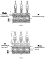
- FIG. 11 shows a stent-valve according to some embodiments that includes a multi- (e.g., three) component fabric reinforcement.
- Each component may have a trapezoid geometry to accommodate the variation of the stent inner diameter over its longitudinal axis.
- the components When the components are sutured together, they may form a cylindrical or part-cylindrical skirt, which is flared at one extremity to avoid constraining the stent and thereby reducing its anchoring force within the annulus.
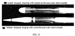
- FIG. 12 shows two configurations for a distal section of a stent-valve delivery system in accordance with some embodiments of the present invention.
- Distal configuration 1202 includes a generally dilator shaped, longer tip with an unreinforced outer stent sheath.
- distal configuration 1204 includes a generally bullet or domed shaped, shorter tip with a coil-reinforced outer stent sheath.
- coil-reinforced sheaths including, for example, extrusion of an inner and an outer tubing, coiling of a stainless steel wire, and assembling the three components by fusion bonding on a mandrel.
- distal configuration 1204 may have improved resistance to kinking due to the bending moment acting onto the delivery system during positioning within, for example, an aortic arch. More specifically, the coil-reinforced stent outer sheath may increase the mechanical kink resistance of the stent delivery system. The use of the bullet shaped tip with reduced length may decrease the bending moment of the delivery system.
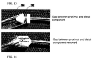
- FIGS. 13 and 14 show two configurations of a stent holder of stent-valve delivery system in accordance with some embodiments of the present invention.
- the stent holder includes proximal and distal components separated by a gap 1302.
- the component actually holding the stent is the middle, metallic component.
- the distal component may be conically shaped to facilitate closing of the sheath and to avoid catching the pins.
- the proximal component may serve as a guide for the attachment elements of the stent and may prevent them from kinking under compression during stent-valve release.
- the distal, metallic, and proximal components may be separate pieces, whereas in other embodiments they may be a single piece of solid construction.
- the proximal and distal components are positioned adjacent to one another and thus the gap is removed, which may reduce or eliminate the risk of catching or damaging the stent outer sheath 1304 when closing the delivery device.
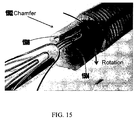
- FIG. 15 shows another configuration of a stent holder in accordance with some embodiments of the present invention.
- one or both of the edges (1502, 1504) located adjacent to element 1506 (e.g., pin) configured for removable attachment to a stent component may be chamfered.
- the stent holder may include multiple (e.g., three) such elements 1506 and adjacent chamfered edge(s). The inclusion of chamfered edge(s) on the surface of the stent holder may help to release the stent-valve from element(s) 1506 of the stent holder when a rotational force is applied, for example, to a hold handle of the delivery system.
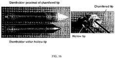
- FIG. 16 shows a stent-valve delivery system in which a distal section of the delivery system has a reduced length (e.g., the length which enters into the ascending aorta) relative to a delivery system with a chamfered distal tip.
- a hollow tip 1602 may be provided that encapsulates the attachment elements/stentholder assembly, which may provide for the reduced length. Placing the attachment elements between the commissural posts may allow for a further reduction in the length of the delivery system.
- FIG. 17 shows a stent-valve delivery system with gear-box type release handle according to some embodiments, which includes opened and closed positions. To move from one position to the other, a rotation of the handle is required prior to translation, thus reducing handling errors.
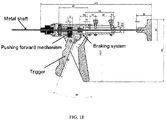
- FIG. 18 shows a stent-valve delivery system with a trigger type release handle according to some embodiments.
- translational movement for opening the delivery system and releasing the stent-valve may be provided by pressing the trigger, thus releasing a braking system and pushing forward the metal shaft connected to the stent outer sheath.
- This system advantageously allows a one hand release of the stent-valve, whereas the other hand takes care of the positioning of the implant.
- the design of this release handle may be similar to, for example, products commercially available for dispensing, for example, silicone.
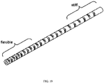
- FIG. 19 shows a mid section of a stent-valve delivery system according to some embodiments, which may include a shaft having a bending stiffness which varies from its proximal to distal ends.
- a stiff proximal shaft may provide for pushability of the delivery system, whereas the flexible distal section may allow for an improved trackability in curves.
- the shaft may include openings (e.g., water jet cut openings) along its longitudinal axis ( FIG. 17 and 19 ), where the openings may be oriented towards two perpendicular axes with respect to the shaft cross section.
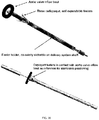
- FIG. 20 shows a positioning device for assisting a physician to implant a stent-valve at an appropriate location according to some embodiments.
- the positioning device comprises three self expanding (e.g. nitinol) fingers or feelers constrained within an outer sheath, which may be co-axially slideable into the stent-valve delivery system. By retracting the outer sheath, the feelers start to expand and can be positioned under the inflow tract of, for example, the aortic valve under fluoroscopic assistance. By exerting a slight force towards the annulus, the three fingers may act as a landmark for implanting the stent-valve.
- three self expanding e.g. nitinol
- feelers By retracting the outer sheath, the feelers start to expand and can be positioned under the inflow tract of, for example, the aortic valve under fluoroscopic assistance.
- the three fingers may act as a landmark for implanting the stent-valve.
- FIGS. 21A-C show a system and corresponding method for positioning and attaching a stent-valve to a stent holder in accordance with some embodiments of the present invention.
- a suture or other pliable, continuous element 2102 e.g., wire
- the stent-valve diameter may be collapsed and the attachment elements may engage the element(s) (e.g., pins 2106) of the stent holder.
- both ends of the suture are free (such that both ends are fed through the tube and then pulled).
- one end of the suture is free whereas the other end is fixed (e.g., to the tubing), such that only one end of the suture is thread through the tubing and pulled.
- outer sheath 2108 may be pulled proximally over the attachment elements, as shown in FIGS. 21B and 21C . The suture may then be removed by pulling it back through the attachment elements.
- FIGS. 22A-C show a system and corresponding method for crimping a stent-valve onto a delivery system according to some embodiments.
- FIG. 22A shows a thin, flat (e.g., polymer or metallic) strip 2202 with a slit 2204 perpendicular to its longitudinal axis and having a wide edge 2206 at one end and a narrower edge 2208 at the opposite end.
- the narrow edge is inserted into the slit (i.e., the slit having a greater height than a height of the narrow edge)
- the strip forms a loop.
- FIGS. 21A-C and 22A-C provide for ease of use by physicians or other technicians. In some embodiments, these positioning and crimping systems may be low cost and disposable, and may be delivered as sterile accessories together with the delivery system and/or the stent-valve.
- stent-valves e.g., single-stent-valves, double-stent-valves
- associated methods and systems for surgery are provided.
- any reference to measurements, distances and the like are for illustrative/example purposes.
- substitutions, alterations, and modifications may be made without departing from the spirit and scope of the invention as defined by the claims.
- Other aspects, advantages, and modifications are considered to be within the scope of the following claims.
- the claims presented are representative of some of the inventions disclosed herein. Other, unclaimed inventions are also contemplated. The applicant reserves the right to pursue such inventions in later claims.
Abstract
Description
- Conventional approaches for cardiac valve replacement require the cutting of a relatively large opening in the patient's sternum ("sternotomy") or thoracic cavity ("thoracotomy") in order to allow the surgeon to access the patient's heart. Additionally, these approaches require arrest of the patient's heart and a cardiopulmonary bypass (i.e., use of a heart-lung bypass machine to oxygenate and circulate the patient's blood). Despite their invasiveness, these surgical approaches may be reasonably safe for a first intervention. However, tissue adherences resulting from the first surgery may increase the risks (e.g., death) associated with subsequent valve replacement surgeries. See Akins et al., "Risk of Reoperative Valve Replacement for Failed Mitral and Aortic Bioprostheses", Ann Thorac Surg 1998;65:1545-52; and Weerasinghe et al., "First Redo Heart Valve Replacement - A 10-Year Analysis", Circulation 1999;99:655-658; each of which is incorporated by reference herein in its entirety.
- Synthetic valves and biological valves have been used for cardiac valve replacement with varying results. Synthetic valves rarely fail but require life-long anti-coagulant treatment to prevent blood from clotting (thrombosis) in and around the replacement valve. Such anti-coagulant treatment significantly limits patients' activities and can cause various other complications. Biological valves do not require such anti-coagulation treatment but typically fail within 10-15 years. Thus, to limit the need for and risks associated with re-operation on failed biological valves, traditionally only patients with less than about 10-15 years to live have received biological valve replacements. Patients with longer life expectan-cies have received synthetic valves and anti-coagulant treatment.
- Attempts have been made to develop less-invasive surgical methods for cardiac valve replacement. These surgical methods, referred to as percutaneous heart valve replacement therapies (PHVT), use a catheter to deliver a replacement valve to an implantation site using the patient's vascular system. These PHVT attempts have various shortcomings, including their inability to ensure proper positioning and stability of the replacement valve within the patient's body.
- In view of the foregoing, it would be desirable to provide improved methods, systems, and devices for cardiac valve replacement.
- Some embodiments of the present invention are directed to systems, methods, and devices for cardiac valve replacement. For example, these methods, systems, and devices may be applicable to the full range of cardiac-valve therapies including the replacement of failed aortic, mitral, tricuspid, and pulmonary valves. In some embodiments, the present invention may facilitate a surgical approach whereby surgery is performed on a beating heart without the need for an open-chest cavity and heart-lung bypass. This minimally-invasive surgical approach may reduce the risks associated with replacing a failed native valve in the first instance, as well as the risks associated with secondary or subsequent surgeries to replace failed artificial (e.g., biological or synthetic) valves. Stent-valves according to some embodiments of the present invention may include a valve component and at least one stent component (e.g., a single-stent-valve or a double-stent-valve). The valve component may include a biological or synthetic (e.g., mechanical) valve and/or any other suitable material(s). The stent and valve components may be capable of at least two configurations: a collapsed configuration (e.g., during delivery) and an expanded configuration (e.g., after implantation).
- In some embodiments, the stent component of a stent-valve may include a first strut and a second strut with ends located at different positions along a longitudinal axis of the stent component, wherein the first strut and the second strut provide an axial resistance for anchoring the stent at an implantation site. Multiple installations of the first strut and the second strut may be provided, where such installations are positioned horizontally along a perimeter of the stent component. In some embodiments, the first strut and the second strut may be connected.
- Alternatively or additionally, the stent-component of a stent valve may include multiple locking elements protruding outwardly from an outer surface of the stent component, where each locking element includes a first end adjacent to the outer surface of the stent component and a second end spaced apart from the outer surface of the stent component. The second end of at least a first locking element may be located at a different position along a longitudinal axis of the stent component than the second end of at least a second locking element. For example, in one embodiment, the first locking element and the second locking element may have substantially the same lengths, and the first ends of the first and second locking elements may be positioned at multiple, different levels along the longitudinal axis of the stent component. In another embodiment, the first locking element and the second locking element may have different lengths, and the first ends of the first and second locking elements may be positioned at substantially the same level along the longitudinal axis of the stent component.
- In some embodiments, the stent component of a stent-valve may include at least a first commissural post and a second commissural post adjacent to a body of the stent component, where the external contours of the first and second commissural posts collectively form a generally concave shape. In some embodiments, each of the external contours may slope inwardly toward the center of the corresponding commissural post in the direction of the body of the stent component. In other embodiments, external contours of adjacent commissural posts may be generally convexly shaped.
- In some embodiments, the valve component of a stent-valve may include an outer surface covered with fabric (e.g., at least a portion thereof, or substantially the entire surface). The valve component may include at least one suture along a free edge of the valve component and at least one suture along an inflow free edge of the valve component, where the fabric includes a skirt that extends below the valve component. A free edge of the skirt may be folded over a bottom portion of the corresponding stent component and sutured to the stent component. In some embodiments, substantially all or at least a portion of the fibers of the fabric are oriented +/- 45 degrees with respect to a longitudinal axis of the valve component. Alternatively or additionally, the stent component may include at least one Y-shaped structure fixed to the valve component by one or more (e.g., 3) sutures forming a corresponding Y-shaped configuration. In some embodiments, the stent component comprises an annular groove and the free edge of the skirt is positioned within the groove. Alternatively or additionally, the free edge of the skirt comprises at least one cut oriented in the direction of a longitudinal axis of the stent component. In some embodiments, the annular groove may be at least partially filled with a fibrous, foam, or other biocompatible material.
- In still other embodiments of the present invention, a stent-valve delivery system is provided. A first assembly is provided that includes an outer sheath and a guide wire tubing. The delivery system also includes a second assembly including a stent holder configured for removable attachment to at least one attachment element of a stent-valve. The stent-valve may be positioned over the guide wire tubing of the first assembly. The first assembly and the second assembly may be configured for relative movement with respect to one another in order to transition from a closed position to an open position. In the closed position, the outer sheath may encompass the stent-valve still attached to the stent holder and thus constrain expansion of the stent-valve. In the open position, the outer sheath may not constrain expansion of the stent-valve and thus the stent-valve may detach from the stent holder and expand to a fully expanded configuration.
- In some embodiments, the first assembly and the second assembly may be configured to transition from the closed position, to a partially-open position, to the open position. In the partially-open position, the stent-valve may expand partially but not detach from the stent holder because the outer sheath may still encompass the at least one attachment element of the stent-valve and the stent holder. When the stent-valve is in the partially-expanded configuration, it may be determined whether the stent-valve will be positioned correctly if the stent-valve is expanded to the fully expanded configuration. Alternatively or additionally, the functionality of the stent-valve may be tested (e.g., to determine whether the stent-valve will permit sufficient blood-flow) when the stent-valve is in the partially-expanded configuration.
- In some embodiments, the first assembly of the stent-valve delivery system may include a coil-reinforced outer sheath and/or a substantially dome-shaped tip, which may provide resistance to kinking due to the bending moment acting onto the delivery system during positioning within, for example, an aortic arch.
- In some embodiments, the stent holder of the delivery system may include proximal and distal components positioned adjacent to one another (i.e., no gap). This may reduce or eliminate the risk of catching or damaging the outer sheath of the first assembly when closing the delivery device.
- In some embodiments, the stent holder may include at least one chamfered edge positioned adjacent to at least one attachment pin of the stent holder, where the at least one attachment pin is configured for removable attachment to an attachment element of a stent component. The chamfered edge may assist with the release and expansion of the stent-valve from the stent holder when the stent holder is rotated axially.
- In still other embodiments of the present invention, an apparatus is provided for positioning and attaching a stent-valve comprising a plurality of attachment elements to a corresponding plurality of attachment pins of a stent holder. The apparatus may include an elongate, pliable member (e.g., suture or wire) configured to be threaded through the plurality of attachment elements. The apparatus may also include a tube for receiving the elongate, pliable member. Pulling the elongate, pliable member through the tubing while holding the tubing in a fixed position may collapse the stent-valve diameter to allow for engagement of the attachment elements to the attachment pins.
- In some embodiments, an apparatus is provided for collapsing a diameter of a stent-valve to allow capture of the stent-valve within a sheath of a delivery system. The apparatus may include an elongate, substantially flat strip comprising a slit positioned perpendicular to a longitudinal axis of the strip. The elongate, substantially flat strip may include an end having a height less than a height of the slit, such that insertion of the end into the slit forms a loop. Upon placement of an expanded stent-valve within the loop, pulling the end through the slit causes a reduction of the loop diameter and thereby collapses the diameter of the stent-valve. The elongate, substantially flat strip may be formed from any suitable material including, for example, polymer and metal.
- For a better understanding of the present invention, reference is made to the following description, taken in conjunction with the accompanying drawings, in which like reference characters refer to like parts throughout, and in which:
-
FIG. 1 shows a stent component that includes single struts in a proximal section of the stent according to some embodiments of the present invention; -
FIG. 2 shows a stent component that includes double struts in a proximal section of the stent according to some embodiments of the present invention; -
FIGS. 3 and 4 show stent components that include multiple locking elements positioned at multiple, different levels such that at least one locking element is located more proximally than another locking element according to some embodiments of the present invention; -
FIGS. 5 and 6 show stent components having, respectively, convex and concave stem configurations according to some embodiments of the present invention; -
FIG. 7 shows a stent component that includes a reinforced proximal section and reinforced attachment elements according to some embodiments of the present invention; -
FIG. 8 shows a stent component that includes attachment elements positioned between commissural posts according to some embodiments of the present invention; -
FIG. 9 shows a fabric reinforcement for a valve component that covers all, or substantially all, of the valve outer surface and forms a skirt according to some embodiments of the present invention. -
FIG. 10 shows details regarding the suturing the valve component and fabric ofFIG. 9 to a stent according to some embodiments of the present invention. -
FIG. 11 shows a stent-valve that includes a multi- (e.g., three) component fabric reinforcement according to some embodiments of the present invention; -
FIG. 12 shows two configurations for the distal section of a stent-valve delivery system according to some embodiments of the present invention; -
FIGS. 13 and 14 show two configurations of a stent holder of stent-valve delivery system according to some embodiments of the present invention; -
FIG. 15 shows a stent holder with at least one chamfered edge according to some embodiments of the present invention; -
FIG. 16 shows a stent-valve delivery system in which a distal section of the delivery system has a reduced length according to some embodiments of the present invention; -
FIG. 17 shows a stent-valve delivery system with gear-box type release handle according to some embodiments of the present invention; -
FIG. 18 shows a stent-valve delivery system with a trigger type release handle according to some embodiments of the present invention; -
FIG. 19 shows a shaft of a stent-valve delivery system that has a bending stiffness which varies from its proximal to distal ends according to some embodiments of the present invention; -
FIG. 20 shows a positioning device for assisting a physician to implant a stent-valve at an appropriate location according to some embodiments of the present invention; -
FIGS. 21A-C show a system and corresponding method for positioning and attaching a stent-valve to a stent holder of a delivery system according to some embodiments of the present invention; and -
FIGS. 22A-C show a system and corresponding method for crimping a stent-valve onto a delivery system according to some embodiments of the present invention. -
FIG. 1 shows a stent component according to some embodiments that includes single struts 102 in a proximal section of the stent.FIG. 2 shows a stent component according to some embodiments that includes two struts (202, 204) in a proximal section of the stent. Such double struts may increase the radial resistance to crush of the stent (e.g., axial resistance) and the out of plane bending stiffness of the stent proximal section, thus improving the anchoring of the stent within, for example, a failed biological valve or a calcified native annulus. InFIG. 1 , multiple (e.g., 10-15 or more) installations of single strut 102 may be provided, for example, side-by-side around the circumference of the stent. InFIG. 2 , first strut 202 and second strut 204 are provided, where second strut 204 may be a reinforcement within first strut 202. -
FIGS. 3 and 4 show some embodiments of stent components that include multiple locking elements positioned at multiple, different levels, such that at least one locking element is located more proximally than another locking element. The locking elements may engage, for example, a failed biological valve or calcified native annulus. InFIG. 3 , the portions of lockingelements 302 located adjacent to the outer surface of the stent component are positioned at multiple, different levels (304 a, b, c) and each lockingelement 302 has the same orsimilar length 306. These locking elements may have a similar out of plane bending stiffness. InFIG. 4 , the portions of lockingelements 402 located adjacent to the outer surface of the stent component are positioned at thesame level 404 and the lockingelements 402 have multiple different lengths (406 a, b, c). In the configuration ofFIG. 4 , theshorter locking elements 402 may have a higher out of plane stiffness. High out of plane bending stiffness may prevent a complete circular expansion of the stent-valve which could result in paravalvular leaks. -
FIGS. 5 and 6 show stent components according to some embodiments having different stem (e.g., commissural post) configurations according to some embodiments of the present invention. As shown inFIG. 5 , each of the external contours (e.g., wires) of adjacent stems 502 and 504 may have a generallyconvex shape 506.FIG. 6 shows another embodiment in which the external contours of adjacent stems (602, 604) collectively form a generally concave shape 606. In some embodiments, the concave shape may also have inward-sloping characteristic(s). For example, as shown inFIG. 6 , each of the external arches slopes inwardly toward the center of the corresponding stem in the direction of thebody 608 of the stent. The inclusion of a concavely-shaped stem may, for example, avoid the contact of the valve leaflets with the expanded stent during systole and improve the blood flow to the coronary arteries. Other embodiments of stent components include, for example, stents that include both convexly- and concavely-shaped stems (e.g., a stent component including at least onestem 502 and at least one stem 602). -
FIG. 7 shows a stent component according to some embodiments that includes reinforcement of a proximal section of the stent with the connection of the double struts 702 (e.g., connection of struts 202 and 204 ofFIG. 2 ). This increases the radial force/resistance to crushing of the stent and the out of plane bending stiffness of the elements forming the proximal section, thus improving the anchoring of the stent-valve within the calcified annulus. Furthermore, the attachment elements are reinforced 704 to reduce the risk of kinking under compression during stent-valve release. Geometry 706 has also been changed (e.g., optimized) to locally reduce stresses and strains. -
FIG. 8 shows a stent component according to some embodiments in which the attachment elements 802 are positioned between the commissural posts. This may reduce the overall stent length and accordingly the length of the delivery system, thus avoiding its distal section entering deeply into the ascending aorta/aortic arch during stent-valve release. -
FIGS. 9 and 10 show additional details regarding stent-valves in accordance with some embodiments of the present invention. InFIG. 9 , a fabric reinforcement is provided that covers all, or substantially all, of the valve outer surface down to theskirt 902. This may prevent pulling out of sutures and wearing of the valve due to contact with the stent. Acontinuous suture 904 along the trimmed aortic sinus may be provided, which may allow for firm fixation of the valve to the stent commissural posts. Together withcontinuous suture 906 along the perimeter of the inflow margin,suture 904 may also increase seal integrity. The fabric that covers the skirt may be integral to and continuous with the fabric that extends betweensutures sutures -
FIG. 10 shows details regarding the suturing the valve and fabric ofFIG. 9 to a stent according to some embodiments of the present invention. As shown, the proximal section of theskirt 1002 may be folded over the proximal flared/grooved proximal stent section. Y-shapedsutures 1004 may be provided that hold the valve firmly within the stent and increase seal integrity. In some embodiments, each Y-shaped connection may be made out of one or more independent sutures, where multiple sutures may be provided to avoid leakage in case of a rupture of any single stitch. Free floatingedge 1006 of the skirt may be positioned within the groove of the stent and may serve as a further blood barrier by promoting clotting. In some embodiments,longitudinal cuts 1008 may be made along the free floating edge between the sutures to build flexible flaps around the circumference of the stent within the groove. This may improve the barrier effect and increase conformability of the skirt. Alternatively or additionally, the sealing of the prosthesis may be improved by at least partially filling the groove with a fibrous, foam like, or other suitable biocompatible material. The skirt may have a smooth inner surface to minimize blood shear at the annular inflow tract of the prosthesis. A more structured surface may be provided on the outer surface of the prosthesis in order to, for example, improve the sealing of the stent-valve at the implantation site. -
FIG. 11 shows a stent-valve according to some embodiments that includes a multi- (e.g., three) component fabric reinforcement. Each component may have a trapezoid geometry to accommodate the variation of the stent inner diameter over its longitudinal axis. When the components are sutured together, they may form a cylindrical or part-cylindrical skirt, which is flared at one extremity to avoid constraining the stent and thereby reducing its anchoring force within the annulus. -
FIG. 12 shows two configurations for a distal section of a stent-valve delivery system in accordance with some embodiments of the present invention.Distal configuration 1202 includes a generally dilator shaped, longer tip with an unreinforced outer stent sheath. In contrast,distal configuration 1204 includes a generally bullet or domed shaped, shorter tip with a coil-reinforced outer stent sheath. Several manufacturing technologies are available for manufacturing such coil-reinforced sheaths including, for example, extrusion of an inner and an outer tubing, coiling of a stainless steel wire, and assembling the three components by fusion bonding on a mandrel. Relative todistal configuration 1202,distal configuration 1204 may have improved resistance to kinking due to the bending moment acting onto the delivery system during positioning within, for example, an aortic arch. More specifically, the coil-reinforced stent outer sheath may increase the mechanical kink resistance of the stent delivery system. The use of the bullet shaped tip with reduced length may decrease the bending moment of the delivery system. -
FIGS. 13 and 14 show two configurations of a stent holder of stent-valve delivery system in accordance with some embodiments of the present invention. InFIG. 13 , the stent holder includes proximal and distal components separated by agap 1302. In some embodiments, the component actually holding the stent is the middle, metallic component. The distal component may be conically shaped to facilitate closing of the sheath and to avoid catching the pins. The proximal component may serve as a guide for the attachment elements of the stent and may prevent them from kinking under compression during stent-valve release. In some embodiments, the distal, metallic, and proximal components may be separate pieces, whereas in other embodiments they may be a single piece of solid construction. InFIG. 14 , the proximal and distal components are positioned adjacent to one another and thus the gap is removed, which may reduce or eliminate the risk of catching or damaging the stentouter sheath 1304 when closing the delivery device. -
FIG. 15 shows another configuration of a stent holder in accordance with some embodiments of the present invention. As shown, one or both of the edges (1502, 1504) located adjacent to element 1506 (e.g., pin) configured for removable attachment to a stent component may be chamfered. In some embodiments, the stent holder may include multiple (e.g., three)such elements 1506 and adjacent chamfered edge(s). The inclusion of chamfered edge(s) on the surface of the stent holder may help to release the stent-valve from element(s) 1506 of the stent holder when a rotational force is applied, for example, to a hold handle of the delivery system. -
FIG. 16 shows a stent-valve delivery system in which a distal section of the delivery system has a reduced length (e.g., the length which enters into the ascending aorta) relative to a delivery system with a chamfered distal tip. A hollow tip 1602 may be provided that encapsulates the attachment elements/stentholder assembly, which may provide for the reduced length. Placing the attachment elements between the commissural posts may allow for a further reduction in the length of the delivery system. -
FIG. 17 shows a stent-valve delivery system with gear-box type release handle according to some embodiments, which includes opened and closed positions. To move from one position to the other, a rotation of the handle is required prior to translation, thus reducing handling errors. -
FIG. 18 shows a stent-valve delivery system with a trigger type release handle according to some embodiments. In such embodiments, translational movement for opening the delivery system and releasing the stent-valve may be provided by pressing the trigger, thus releasing a braking system and pushing forward the metal shaft connected to the stent outer sheath. This system advantageously allows a one hand release of the stent-valve, whereas the other hand takes care of the positioning of the implant. The design of this release handle may be similar to, for example, products commercially available for dispensing, for example, silicone. -
FIG. 19 shows a mid section of a stent-valve delivery system according to some embodiments, which may include a shaft having a bending stiffness which varies from its proximal to distal ends. A stiff proximal shaft may provide for pushability of the delivery system, whereas the flexible distal section may allow for an improved trackability in curves. The shaft may include openings (e.g., water jet cut openings) along its longitudinal axis (FIG. 17 and19 ), where the openings may be oriented towards two perpendicular axes with respect to the shaft cross section. -
FIG. 20 shows a positioning device for assisting a physician to implant a stent-valve at an appropriate location according to some embodiments. The positioning device comprises three self expanding (e.g. nitinol) fingers or feelers constrained within an outer sheath, which may be co-axially slideable into the stent-valve delivery system. By retracting the outer sheath, the feelers start to expand and can be positioned under the inflow tract of, for example, the aortic valve under fluoroscopic assistance. By exerting a slight force towards the annulus, the three fingers may act as a landmark for implanting the stent-valve. -
FIGS. 21A-C show a system and corresponding method for positioning and attaching a stent-valve to a stent holder in accordance with some embodiments of the present invention. As shown inFIG. 21A , a suture or other pliable, continuous element 2102 (e.g., wire) may be threaded through the attachment elements of the stent component and then through a cannula or tubing 2104. By pulling the suture and holding the tubing, the stent-valve diameter may be collapsed and the attachment elements may engage the element(s) (e.g., pins 2106) of the stent holder. In some embodiment, both ends of the suture are free (such that both ends are fed through the tube and then pulled). In other embodiments, one end of the suture is free whereas the other end is fixed (e.g., to the tubing), such that only one end of the suture is thread through the tubing and pulled. Subsequently, outer sheath 2108 may be pulled proximally over the attachment elements, as shown inFIGS. 21B and 21C . The suture may then be removed by pulling it back through the attachment elements. -
FIGS. 22A-C show a system and corresponding method for crimping a stent-valve onto a delivery system according to some embodiments.FIG. 22A shows a thin, flat (e.g., polymer or metallic) strip 2202 with a slit 2204 perpendicular to its longitudinal axis and having awide edge 2206 at one end and a narrower edge 2208 at the opposite end. When the narrow edge is inserted into the slit (i.e., the slit having a greater height than a height of the narrow edge), the strip forms a loop. As shown inFIGS. 22B and 22C , when a stent-valve is placed within the loop, pulling on the edges at the two extremities of the strip causes a reduction of the loop diameter 2210 thereby crimping the stent-valve. The crimped stent-valve can then be stepwise constrained by theouter sheath 2212. Generally, the positioning and crimping systems shown inFIGS. 21A-C and 22A-C provide for ease of use by physicians or other technicians. In some embodiments, these positioning and crimping systems may be low cost and disposable, and may be delivered as sterile accessories together with the delivery system and/or the stent-valve. - Thus it is seen that stent-valves (e.g., single-stent-valves, double-stent-valves) and associated methods and systems for surgery are provided. Although particular embodiments have been disclosed herein in detail, this has been done by way of example for purposes of example and illustration only, and is not intended to be limiting with respect to the scope of the appended claims, which follow. To that end, any reference to measurements, distances and the like, are for illustrative/example purposes. In particular, it is contemplated by the applicant that various substitutions, alterations, and modifications may be made without departing from the spirit and scope of the invention as defined by the claims. Other aspects, advantages, and modifications are considered to be within the scope of the following claims. The claims presented are representative of some of the inventions disclosed herein. Other, unclaimed inventions are also contemplated. The applicant reserves the right to pursue such inventions in later claims.
- Further novel and inventive paragraphs are set out in the following paragraphs:
- 1. A replacement valve for use within a human body comprising:
- a valve component; and
- a stent component for housing the valve component, a proximal portion of the stent component comprising a first strut and a second strut with ends located at different positions along a longitudinal axis of the stent component, wherein the first strut and the second strut provide an axial resistance for anchoring the stent at an implantation site.
- 2. The replacement valve of
paragraph 1, wherein the stent component comprises multiple installations of said first strut and said second strut located horizontally along the perimeter of the stent component, and wherein said second strut is located within said first strut. - 3. The replacement valve of
paragraph 1, wherein the end of the second strut is connected to the end of the first strut. - 4. A replacement valve for use within a human body comprising:
- a valve component; and
- a stent component for housing the valve component, the stent component comprising a plurality of locking elements protruding outwardly from an outer surface of the stent component, each locking element including a first end adjacent to the outer surface of the stent component and a second end spaced apart from the outer surface of the stent component, wherein the second end of at least a first locking element is located at a different position along a longitudinal axis of the stent component than the second end of at least a second locking element.
- 5. The replacement valve of paragraph 4, wherein the first locking element and the second locking element have substantially the same lengths and wherein the first ends of the first and second locking elements are positioned at multiple, different levels along the longitudinal axis of the stent component.
- 6. The replacement valve of paragraph 4, wherein the first locking element and the second locking element have different lengths and wherein the first ends of the first and second locking elements are positioned at substantially the same level along the longitudinal axis of the stent component.
- 7. A replacement valve for use within a human body comprising:
- a valve component; and
- a stent component for housing the valve component, the stent component comprising at least a first commissural post and a second commissural adjacent to a body of the stent component, wherein the first commissural post comprises an external contour and the second commissural post comprises an external contour that collectively form a generally concave shape, and wherein at least one of the external contours slopes inwardly toward the center of the corresponding commissural post in the direction of the body of the stent component.
- 8. A replacement valve for use within a human body comprising:
- a valve component comprising an outer surface substantially entirely covered with fabric, the valve component comprising at least one suture along the trimmed aortic sinus and at least one suture along the perimeter of the inflow margin, the fabric comprising a skirt that extends below the valve component; and
- a stent component for housing the valve component,
- wherein a free edge of the skirt is folded over a bottom portion of the stent component and sutured to the stent component.
- 9. The replacement valve of paragraph 8, wherein substantially all the fibers of the fabric are oriented about +/- 45 degrees with respect to a longitudinal axis of the valve component.
- 10. The replacement valve of paragraph 8, wherein the stent component comprises at least one Y-shaped structure fixed to the valve component by one or more sutures forming a corresponding Y-shaped configuration.
- 11. The replacement valve of paragraph 8, wherein the stent component comprises an annular groove and wherein the free edge of the skirt is positioned within the annular groove.
- 12. The replacement valve of paragraph 11, wherein the free edge of the skirt comprises at least one cut oriented in the direction of a longitudinal axis of the stent component.
- 13. The replacement valve of paragraph 11, wherein the annular groove is at least partially filled with a fibrous, foam, or other biocompatible material.
- 14. A cardiac stent-valve delivery system comprising:
- a first assembly comprising a coil-reinforced outer sheath, a substantially dome-shaped tip, and a guide wire tubing; and
- a second assembly comprising a stent holder configured for removable attachment to at least one attachment element of a stent-valve, the stent-valve positioned over the guide wire tubing of the first assembly,
- wherein the first assembly and the second assembly are configured for relative movement with respect to one another in order to transition from a closed position to an open position, such that in the closed position the outer sheath encompasses the stent-valve still attached to the stent holder and thus constrains expansion of the stent-valve, and such that in the open position the outer sheath does not constrain expansion of the stent-valve and thus the stent-valve detaches from the stent holder and expands to a fully expanded configuration.
- 15. A cardiac stent-valve delivery system comprising:
- a first assembly comprising an outer sheath and a guide wire tubing; and
- a second assembly comprising a stent holder configured for removable attachment to at least one attachment element of a stent-valve, the stent-valve positioned over the guide wire tubing of the first assembly, wherein the stent holder comprises proximal and distal components positioned adjacent to one another,
- wherein the first assembly and the second assembly are configured for relative movement with respect to one another in order to transition from a closed position to an open position, such that in the closed position the outer sheath encompasses the stent-valve still attached to the stent holder and thus constrains expansion of the stent-valve, and such that in the open position the outer sheath does not constrain expansion of the stent-valve and thus the stent-valve detaches from the stent holder and expands to a fully expanded configuration.
- 16. A cardiac stent-valve delivery system comprising:
- a first assembly comprising an outer sheath and a guide wire tubing; and
- a second assembly comprising a stent holder configured for removable attachment via at least one attachment pin to at least one attachment element of a stent-valve, the stent-valve positioned over the guide wire tubing of the first assembly, wherein the stent holder comprises at least one chamfered edge adjacent to the at least one attachment pin,
- wherein the first assembly and the second assembly are configured for relative movement with respect to one another in order to transition from a closed position to an open position, such that in the closed position the outer sheath encompasses the stent-valve still attached to the stent holder and thus constrains expansion of the stent-valve, and such that in the open position the outer sheath does not constrain expansion of the stent-valve and thus the stent-valve detaches from the stent holder and expands to a fully expanded configuration, and
- wherein the chamfered edge is configured to assist with the release and expansion of the stent-valve from the stent holder when the stent holder is rotated axially.
- 17. Apparatus for positioning and attaching a stent-valve comprising a plurality of attachment elements to a corresponding plurality of attachment pins of a stent holder of a delivery device, the apparatus comprising:
- an elongate, pliable member configured to be threaded through the plurality of attachment elements; and
- a tube for receiving the elongate, pliable member,
- wherein pulling the elongate, pliable member through the tubing while holding the tubing in a fixed position collapses the stent-valve diameter to allow for engagement of the attachment elements to the attachment pins.
- 18. The apparatus of paragraph 17, wherein the elongate, pliable member comprises a suture.
- 19. The apparatus of paragraph 17, wherein the elongate, pliable member comprises a wire.
- 20. Apparatus for collapsing a diameter of a stent-valve to allow capture of the stent-valve within a sheath of a delivery system, the apparatus comprising:
- an elongate, substantially flat strip comprising a slit positioned perpendicular to a longitudinal axis of the strip, the elongate, substantially flat strip comprising an end having a height less than a height of the slit, such that insertion of the end into the slit forms a loop,
- wherein upon placement of an expanded stent-valve within the loop, pulling the end through the slit causes a reduction of the loop diameter and thereby collapses the diameter of a stent-valve.
- 21. The apparatus of
paragraph 20, wherein the elongate, substantially flat strip comprises a polymer. - 22. The apparatus of
paragraph 20, wherein the elongate, substantially flat strip comprises metal. - 23. A replacement valve for use within a human body comprising:
- a valve component; and
- a stent component for housing the valve component, the stent component comprising at least two commissural posts and at least one attachment element for attaching to a delivery device, wherein the at least one attachment element is positioned between the at least two commissural posts.
- 24. A replacement valve for use within a human body comprising:
- a stent-valve; and
- a fabric reinforcement for at least partially covering the stent-valve, wherein the fabric reinforcement comprises a plurality of trapezoidal segments.
- 25. A cardiac stent-valve delivery system comprising:
- a first assembly comprising an outer sheath and a guide wire tubing, the first assembly further comprising a distal tip with a hollow interior; and
- a second assembly comprising a stent holder configured for removable attachment via at least one attachment pin to at least one attachment element of a stent-valve, the stent-valve positioned over the guide wire tubing of the first assembly, the at least one attachment element/attachment pin being configured for receipt within the hollow interior of the distal tip,
- wherein the first assembly and the second assembly are configured for relative movement with respect to one another in order to transition from a closed position to an open position, such that in the closed position the outer sheath encompasses the stent-valve still attached to the stent holder and thus constrains expansion of the stent-valve, and such that in the open position the outer sheath does not constrain expansion of the stent-valve and thus the stent-valve detaches from the stent holder and expands to a fully expanded configuration.
- 26. A cardiac stent-valve delivery system comprising:
- a first assembly and a second assembly configured for relative movement with respect to one another in order to transition from a closed position to an open position, such that in the closed position an outer sheath encompasses the stent-valve still attached to a stent holder and thus constrains expansion of the stent-valve, and such that in the open position the outer sheath does not constrain expansion of the stent-valve and thus the stent-valve detaches from the stent holder and expands to a fully expanded configuration, wherein the transition from the closed position to the open position is effectuated by a gear-box handle.
- 27. A cardiac stent-valve delivery system comprising:
- a first assembly and a second assembly configured for relative movement with respect to one another in order to transition from a closed position to an open position, such that in the closed position an outer sheath encompasses the stent-valve still attached to a stent holder and thus constrains expansion of the stent-valve, and such that in the open position the outer sheath does not constrain expansion of the stent-valve and thus the stent-valve detaches from the stent holder and expands to a fully expanded configuration, wherein the transition from the closed position to the open position is effectuated by a trigger handle.
- 28. A cardiac stent-valve delivery system comprising:
- a shaft comprising a proximal end and a distal end, wherein the bending stiffness of the shaft varies from the proximal end to the distal end.
- 29. Apparatus for use in implanting a stent-valve at an implantation site comprising:
- an elongate member comprising a plurality of self-expanding members and configured for placement within an outer sheath of a stent-valve delivery system, wherein expansion of the members occurs upon retracting the outer sheath.
- 30. A replacement valve for use within a human body comprising:
- a valve component; and
- a stent component for housing the valve component, a proximal portion of the stent component comprising a first strut and a second strut with ends located at different positions along a longitudinal axis of the stent component, wherein the first strut and the second strut provide an axial resistance for anchoring the stent at an implantation site.
- 31. The replacement valve of paragraph 30, wherein the stent component comprises multiple installations of said first strut and said second strut located horizontally along the perimeter of the stent component, and wherein said second strut is located within said first strut.
- 32. The replacement valve of paragraph 30, wherein the end of the second strut is connected to the end of the first strut.
- 33. A replacement valve for use within a human body comprising:
- a valve component; and
- a stent component for housing the valve component, the stent component comprising a plurality of locking elements protruding outwardly from an outer surface of the stent component, each locking element including a first end adjacent to the outer surface of the stent component and a second end spaced apart from the outer surface of the stent component, wherein the second end of at least a first locking element is located at a different position along a longitudinal axis of the stent component than the second end of at least a second locking element.
- 34. The replacement valve of paragraph 33, wherein the first locking element and the second locking element have substantially the same lengths and wherein the first ends of the first and second locking elements are positioned at multiple, different levels along the longitudinal axis of the stent component.
- 35. The replacement valve of paragraph 33, wherein the first locking element and the second locking element have different lengths and wherein the first ends of the first and second locking elements are positioned at substantially the same level along the longitudinal axis of the stent component.
- 36. The replacement valve of paragraph 30 or 33, wherein the stent component further comprises at least a first commissural post and a second commissural adjacent to a body of the stent component, wherein the first commissural post comprises an external contour and the second commissural post comprises an external contour that collectively form a generally concave shape, and wherein at least one of the external contours slopes inwardly toward the center of the corresponding commissural post in the direction of the body of the stent component.
- 37. The replacement valve of paragraph 30 or 33, wherein the replacement valve further comprises a valve component comprising an outer surface substantially entirely covered with fabric, the valve component comprising at least one suture along the trimmed aortic sinus and at least one suture along the perimeter of the inflow margin, the fabric comprising a skirt that extends below the valve component; and
a stent component for housing the valve component,
wherein a free edge of the skirt is folded over a bottom portion of the stent component and sutured to the stent component. - 38. The replacement valve of paragraph 37, wherein substantially all the fibers of the fabric are oriented +/- 45 degrees with respect to a longitudinal axis of the valve component.
- 39. The replacement valve of paragraph 37, wherein the stent component comprises at least one Y-shaped structure fixed to the valve component by one or more sutures forming a corresponding Y-shaped configuration.
- 40. The replacement valve of paragraph 37, wherein the stent component comprises an annular groove and wherein the free edge of the skirt is positioned within the annular groove.
- 41. The replacement valve of paragraph 40, wherein the free edge of the skirt comprises at least one cut oriented in the direction of a longitudinal axis of the stent component.
- 42. The replacement valve of paragraph 40, wherein the annular groove is at least partially filled with a fibrous, foam, or other biocompatible material.
Claims (14)
- A replacement valve for use within a human body, comprising:a valve component, anda stent component for housing the valve component;the stent component and the valve components being capable of at least a collapsed configuration for delivery, and an expanded configuration after implantation.
- The replacement valve according to claim 1, wherein:the valve component comprises an outer surface, at least a portion thereof being covered with fabric, andthe fabric comprises a skirt, the skirt comprises multiple components sutured together.
- The replacement valve according to claim 2, wherein the skirt has a smooth inner surface to minimize blood shear at the annular inflow tract of the prosthesis, and a more structured surface on the outer surface of the prosthesis in order to improve sealing of the prosthesis at an implantation site.
- The replacement valve according to claim 2 or 3, wherein the sutured components form a cylindrical or part-cylindrical skirt.
- The replacement valve according to one of the claims 2, 3 or 4, wherein the skirt is flared at one extremity.
- The replacement valve according to any of claims 2 to 5, wherein the skirt (902, 1002) comprises a free edge which is folded over a bottom portion of the stent component and sutured to the stent component.
- The replacement valve according to any of claims 2 to 5, wherein the free edge of the skirt comprises at least one cut (1008).
- The replacement valve according to claim 7, wherein the at least one cut is oriented in a direction of a longitudinal axis of the stent component.
- The replacement valve according to claim 7 or 8, wherein the at least one cut is made along a free-floating edge of the skirt between sutures of the free edge of the skirt.
- The replacement valve according to any of claims 2 to 6, wherein the skirt (902, 1002) comprises a plurality of cuts (1008) along a free floating edge (1006) of the skirt (902, 1002) between sutures of a free edge of the skirt (902, 1002) to build flexible flaps around the circumference of the stent component.
- The replacement valve according to any of claims 2 to 10, wherein at least a portion of the fibers of the fabric are oriented +/- 45 degrees with respect to a longitudinal axis of the valve component and/or of the replacement valve.
- The replacement valve according to claim 1, further comprising a fabric having fibers substantially all of which are arranged at +/- 45 degrees with respect to a longitudinal axis of the valve component and/or replacement valve, and wherein the valve component has an outer surface, at least a portion of the outer surface being covered by the fabric.
- The replacement valve according to claim 12, wherein the fabric comprises a skirt that extends below the valve component.
- The replacement valve according to any preceding claim, wherein the valve component comprises at least one suture along an inflow free edge of the valve component.
Priority Applications (1)
| Application Number | Priority Date | Filing Date | Title |
|---|---|---|---|
| EP18204076.6A EP3492043A3 (en) | 2007-08-21 | 2008-08-21 | A replacement valve |
Applications Claiming Priority (3)
| Application Number | Priority Date | Filing Date | Title |
|---|---|---|---|
| US96578007P | 2007-08-21 | 2007-08-21 | |
| EP08806901.8A EP2219558B8 (en) | 2007-08-21 | 2008-08-21 | Stent-valves for valve replacement and associated systems for surgery |
| EP15169678.8A EP2949292B8 (en) | 2007-08-21 | 2008-08-21 | Replacement valve |
Related Parent Applications (3)
| Application Number | Title | Priority Date | Filing Date |
|---|---|---|---|
| EP08806901.8A Division EP2219558B8 (en) | 2007-08-21 | 2008-08-21 | Stent-valves for valve replacement and associated systems for surgery |
| EP15169678.8A Division-Into EP2949292B8 (en) | 2007-08-21 | 2008-08-21 | Replacement valve |
| EP15169678.8A Division EP2949292B8 (en) | 2007-08-21 | 2008-08-21 | Replacement valve |
Related Child Applications (1)
| Application Number | Title | Priority Date | Filing Date |
|---|---|---|---|
| EP18204076.6A Division EP3492043A3 (en) | 2007-08-21 | 2008-08-21 | A replacement valve |
Publications (2)
| Publication Number | Publication Date |
|---|---|
| EP3081194A2 true EP3081194A2 (en) | 2016-10-19 |
| EP3081194A3 EP3081194A3 (en) | 2016-12-07 |
Family
ID=40220239
Family Applications (5)
| Application Number | Title | Priority Date | Filing Date |
|---|---|---|---|
| EP18204076.6A Pending EP3492043A3 (en) | 2007-08-21 | 2008-08-21 | A replacement valve |
| EP15169678.8A Revoked EP2949292B8 (en) | 2007-08-21 | 2008-08-21 | Replacement valve |
| EP16152466.5A Revoked EP3045147B8 (en) | 2007-08-21 | 2008-08-21 | A replacement valve |
| EP16162669.2A Withdrawn EP3081194A3 (en) | 2007-08-21 | 2008-08-21 | A replacement valve |
| EP08806901.8A Active EP2219558B8 (en) | 2007-08-21 | 2008-08-21 | Stent-valves for valve replacement and associated systems for surgery |
Family Applications Before (3)
| Application Number | Title | Priority Date | Filing Date |
|---|---|---|---|
| EP18204076.6A Pending EP3492043A3 (en) | 2007-08-21 | 2008-08-21 | A replacement valve |
| EP15169678.8A Revoked EP2949292B8 (en) | 2007-08-21 | 2008-08-21 | Replacement valve |
| EP16152466.5A Revoked EP3045147B8 (en) | 2007-08-21 | 2008-08-21 | A replacement valve |
Family Applications After (1)
| Application Number | Title | Priority Date | Filing Date |
|---|---|---|---|
| EP08806901.8A Active EP2219558B8 (en) | 2007-08-21 | 2008-08-21 | Stent-valves for valve replacement and associated systems for surgery |
Country Status (5)
| Country | Link |
|---|---|
| US (2) | US10716662B2 (en) |
| EP (5) | EP3492043A3 (en) |
| DE (4) | DE202008018551U1 (en) |
| ES (2) | ES2586121T3 (en) |
| WO (1) | WO2009024859A2 (en) |
Families Citing this family (130)
| Publication number | Priority date | Publication date | Assignee | Title |
|---|---|---|---|---|
| DE102005003632A1 (en) | 2005-01-20 | 2006-08-17 | Fraunhofer-Gesellschaft zur Förderung der angewandten Forschung e.V. | Catheter for the transvascular implantation of heart valve prostheses |
| US20070213813A1 (en) | 2005-12-22 | 2007-09-13 | Symetis Sa | Stent-valves for valve replacement and associated methods and systems for surgery |
| US7896915B2 (en) | 2007-04-13 | 2011-03-01 | Jenavalve Technology, Inc. | Medical device for treating a heart valve insufficiency |
| ES2586121T3 (en) | 2007-08-21 | 2016-10-11 | Symetis Sa | Replacement valve |
| DE102007043830A1 (en) | 2007-09-13 | 2009-04-02 | Lozonschi, Lucian, Madison | Heart valve stent |
| JP5628673B2 (en) | 2007-09-26 | 2014-11-19 | セント ジュード メディカル インコーポレイテッド | Foldable prosthetic heart valve |
| US9532868B2 (en) | 2007-09-28 | 2017-01-03 | St. Jude Medical, Inc. | Collapsible-expandable prosthetic heart valves with structures for clamping native tissue |
| US9044318B2 (en) | 2008-02-26 | 2015-06-02 | Jenavalve Technology Gmbh | Stent for the positioning and anchoring of a valvular prosthesis |
| WO2011104269A1 (en) | 2008-02-26 | 2011-09-01 | Jenavalve Technology Inc. | Stent for the positioning and anchoring of a valvular prosthesis in an implantation site in the heart of a patient |
| US8313525B2 (en) | 2008-03-18 | 2012-11-20 | Medtronic Ventor Technologies, Ltd. | Valve suturing and implantation procedures |
| EP3025681B1 (en) | 2008-07-15 | 2017-02-01 | St. Jude Medical, Inc. | Collabsible and re-expandable prosthetic heart valve cuff designs and complementary technological applications |
| EP3753534A1 (en) | 2008-09-29 | 2020-12-23 | Edwards Lifesciences CardiAQ LLC | Heart valve |
| EP2341871B1 (en) | 2008-10-01 | 2017-03-22 | Edwards Lifesciences CardiAQ LLC | Delivery system for vascular implant |
| US8690936B2 (en) | 2008-10-10 | 2014-04-08 | Edwards Lifesciences Corporation | Expandable sheath for introducing an endovascular delivery device into a body |
| CA2961053C (en) | 2009-04-15 | 2019-04-30 | Edwards Lifesciences Cardiaq Llc | Vascular implant and delivery system |
| CN107260367B (en) | 2009-11-02 | 2019-11-29 | 西美蒂斯股份公司 | Aorta bioprosthesis and the system delivered for it |
| US8449599B2 (en) | 2009-12-04 | 2013-05-28 | Edwards Lifesciences Corporation | Prosthetic valve for replacing mitral valve |
| EP2509538B1 (en) | 2009-12-08 | 2017-09-20 | Avalon Medical Ltd. | Device and system for transcatheter mitral valve replacement |
| EP2542184B1 (en) * | 2010-03-01 | 2016-05-25 | Colibri Heart Valve LLC | Percutaneously deliverable heart valve and methods associated therewith |
| PT3335670T (en) | 2010-03-05 | 2022-07-27 | Edwards Lifesciences Corp | Retaining mechanisms for prosthetic valves |
| US8926692B2 (en) | 2010-04-09 | 2015-01-06 | Medtronic, Inc. | Transcatheter prosthetic heart valve delivery device with partial deployment and release features and methods |
| EP3581151B1 (en) | 2010-04-21 | 2021-03-10 | Medtronic, Inc. | Prosthetic valve with sealing members |
| US8579964B2 (en) | 2010-05-05 | 2013-11-12 | Neovasc Inc. | Transcatheter mitral valve prosthesis |
| CN103002833B (en) | 2010-05-25 | 2016-05-11 | 耶拿阀门科技公司 | Artificial heart valve and comprise artificial heart valve and support through conduit carry interior prosthese |
| AU2011275468B2 (en) | 2010-07-09 | 2014-02-06 | Highlife Sas | Transcatheter atrio-ventricular valve prosthesis |
| EP2595569A4 (en) | 2010-07-23 | 2016-02-24 | Edwards Lifesciences Corp | Retaining mechanisms for prosthetic valves |
| CA2808673C (en) | 2010-09-10 | 2019-07-02 | Symetis Sa | Valve replacement devices, delivery device for a valve replacement device and method of production of a valve replacement device |
| PT3626208T (en) | 2010-10-05 | 2021-04-22 | Edwards Lifesciences Corp | Prosthetic heart valve |
| AU2011343755A1 (en) | 2010-12-14 | 2013-06-06 | Colibri Heart Valve Llc | Percutaneously deliverable heart valve including folded membrane cusps with integral leaflets |
| EP2484309B1 (en) | 2011-02-02 | 2019-04-10 | Shlomo Gabbay | Heart valve prosthesis |
| US9308087B2 (en) | 2011-04-28 | 2016-04-12 | Neovasc Tiara Inc. | Sequentially deployed transcatheter mitral valve prosthesis |
| US9173736B2 (en) * | 2011-04-28 | 2015-11-03 | Medtronic Vascular, Inc. | Method of making an endoluminal vascular prosthesis |
| US9554897B2 (en) | 2011-04-28 | 2017-01-31 | Neovasc Tiara Inc. | Methods and apparatus for engaging a valve prosthesis with tissue |
| CA2957442C (en) | 2011-08-11 | 2019-06-04 | Tendyne Holdings, Inc. | Improvements for prosthetic valves and related inventions |
| CA3051684C (en) | 2011-12-06 | 2020-06-16 | Aortic Innovations Llc | Device for endovascular aortic repair and method of using the same |
| US9827092B2 (en) | 2011-12-16 | 2017-11-28 | Tendyne Holdings, Inc. | Tethers for prosthetic mitral valve |
| US11207176B2 (en) | 2012-03-22 | 2021-12-28 | Boston Scientific Scimed, Inc. | Transcatheter stent-valves and methods, systems and devices for addressing para-valve leakage |
| US20130274873A1 (en) | 2012-03-22 | 2013-10-17 | Symetis Sa | Transcatheter Stent-Valves and Methods, Systems and Devices for Addressing Para-Valve Leakage |
| US9999501B2 (en) | 2012-04-18 | 2018-06-19 | Medtronic CV Luxembourg S.a.r.l. | Valve prosthesis |
| US9345573B2 (en) | 2012-05-30 | 2016-05-24 | Neovasc Tiara Inc. | Methods and apparatus for loading a prosthesis onto a delivery system |
| WO2014022124A1 (en) | 2012-07-28 | 2014-02-06 | Tendyne Holdings, Inc. | Improved multi-component designs for heart valve retrieval device, sealing structures and stent assembly |
| WO2014021905A1 (en) | 2012-07-30 | 2014-02-06 | Tendyne Holdings, Inc. | Improved delivery systems and methods for transcatheter prosthetic valves |
| US20140067048A1 (en) | 2012-09-06 | 2014-03-06 | Edwards Lifesciences Corporation | Heart Valve Sealing Devices |
| US9226823B2 (en) | 2012-10-23 | 2016-01-05 | Medtronic, Inc. | Valve prosthesis |
| WO2014081796A1 (en) | 2012-11-21 | 2014-05-30 | Edwards Lifesciences Corporation | Retaining mechanisms for prosthetic heart valves |
| US9439763B2 (en) | 2013-02-04 | 2016-09-13 | Edwards Lifesciences Corporation | Prosthetic valve for replacing mitral valve |
| US10583002B2 (en) | 2013-03-11 | 2020-03-10 | Neovasc Tiara Inc. | Prosthetic valve with anti-pivoting mechanism |
| US9681951B2 (en) | 2013-03-14 | 2017-06-20 | Edwards Lifesciences Cardiaq Llc | Prosthesis with outer skirt and anchors |
| EP3616652B1 (en) * | 2013-03-15 | 2020-07-29 | Symetis SA | Improvements relating to transcatheter stent-valves |
| US9486306B2 (en) | 2013-04-02 | 2016-11-08 | Tendyne Holdings, Inc. | Inflatable annular sealing device for prosthetic mitral valve |
| US10463489B2 (en) | 2013-04-02 | 2019-11-05 | Tendyne Holdings, Inc. | Prosthetic heart valve and systems and methods for delivering the same |
| US11224510B2 (en) | 2013-04-02 | 2022-01-18 | Tendyne Holdings, Inc. | Prosthetic heart valve and systems and methods for delivering the same |
| US9572665B2 (en) | 2013-04-04 | 2017-02-21 | Neovasc Tiara Inc. | Methods and apparatus for delivering a prosthetic valve to a beating heart |
| US10478293B2 (en) | 2013-04-04 | 2019-11-19 | Tendyne Holdings, Inc. | Retrieval and repositioning system for prosthetic heart valve |
| US9610159B2 (en) | 2013-05-30 | 2017-04-04 | Tendyne Holdings, Inc. | Structural members for prosthetic mitral valves |
| CN108814772B (en) | 2013-06-25 | 2020-09-08 | 坦迪尼控股股份有限公司 | Thrombus management and structural compliance features for prosthetic heart valves |
| US9237948B2 (en) * | 2013-07-11 | 2016-01-19 | Medtronic, Inc. | Delivery system with projections |
| AU2014296087B2 (en) | 2013-08-01 | 2019-08-01 | Tendyne Holdings, Inc. | Epicardial anchor devices and methods |
| JP6563394B2 (en) | 2013-08-30 | 2019-08-21 | イェーナヴァルヴ テクノロジー インコーポレイテッド | Radially foldable frame for an artificial valve and method for manufacturing the frame |
| US10195028B2 (en) | 2013-09-10 | 2019-02-05 | Edwards Lifesciences Corporation | Magnetic retaining mechanisms for prosthetic valves |
| WO2015038458A1 (en) | 2013-09-12 | 2015-03-19 | St. Jude Medical, Cardiology Division, Inc. | Stent designs for prosthetic heart valves |
| GB201316349D0 (en) | 2013-09-13 | 2013-10-30 | Ucl Business Plc | Vascular implant |
| WO2015058039A1 (en) | 2013-10-17 | 2015-04-23 | Robert Vidlund | Apparatus and methods for alignment and deployment of intracardiac devices |
| EP3656353A1 (en) | 2013-10-28 | 2020-05-27 | Tendyne Holdings, Inc. | Prosthetic heart valve and systems for delivering the same |
| US9526611B2 (en) | 2013-10-29 | 2016-12-27 | Tendyne Holdings, Inc. | Apparatus and methods for delivery of transcatheter prosthetic valves |
| EP2870946B1 (en) | 2013-11-06 | 2018-10-31 | St. Jude Medical, Cardiology Division, Inc. | Paravalvular leak sealing mechanism |
| US9913715B2 (en) | 2013-11-06 | 2018-03-13 | St. Jude Medical, Cardiology Division, Inc. | Paravalvular leak sealing mechanism |
| US9820852B2 (en) | 2014-01-24 | 2017-11-21 | St. Jude Medical, Cardiology Division, Inc. | Stationary intra-annular halo designs for paravalvular leak (PVL) reduction—active channel filling cuff designs |
| US20150209141A1 (en) | 2014-01-24 | 2015-07-30 | St. Jude Medical, Cardiology Division, Inc. | Stationary intra-annular halo designs for paravalvular leak (pvl) reduction-passive channel filling cuff designs |
| WO2015120122A2 (en) | 2014-02-05 | 2015-08-13 | Robert Vidlund | Apparatus and methods for transfemoral delivery of prosthetic mitral valve |
| US9986993B2 (en) | 2014-02-11 | 2018-06-05 | Tendyne Holdings, Inc. | Adjustable tether and epicardial pad system for prosthetic heart valve |
| CN106068109B (en) | 2014-03-10 | 2019-07-23 | 坦迪尼控股股份有限公司 | Device and method for positioning and monitoring the tether load of prosthetic mitral valve |
| EP3125826B1 (en) | 2014-03-31 | 2020-10-07 | St. Jude Medical, Cardiology Division, Inc. | Paravalvular sealing via extended cuff mechanisms |
| US9532870B2 (en) | 2014-06-06 | 2017-01-03 | Edwards Lifesciences Corporation | Prosthetic valve for replacing a mitral valve |
| US10195026B2 (en) | 2014-07-22 | 2019-02-05 | Edwards Lifesciences Corporation | Mitral valve anchoring |
| US10058424B2 (en) | 2014-08-21 | 2018-08-28 | Edwards Lifesciences Corporation | Dual-flange prosthetic valve frame |
| JP6700278B2 (en) | 2014-12-04 | 2020-05-27 | エドワーズ ライフサイエンシーズ コーポレイションEdwards Lifesciences Corporation | Percutaneous clips for repairing heart valves |
| JP6826035B2 (en) | 2015-01-07 | 2021-02-03 | テンダイン ホールディングス,インコーポレイテッド | Artificial mitral valve, and devices and methods for its delivery |
| CN107427355B (en) * | 2015-02-02 | 2021-08-10 | 赛姆斯股份公司 | Stent seal and method of making same |
| CN107896484B (en) | 2015-02-05 | 2020-09-08 | 坦迪尼控股股份有限公司 | Expandable epicardial pad and delivery devices and methods therefor |
| JP6694948B2 (en) | 2015-04-16 | 2020-05-20 | テンダイン ホールディングス,インコーポレイテッド | Device and method for delivery, repositioning and retrieval of a transcatheter prosthetic valve |
| US10010417B2 (en) | 2015-04-16 | 2018-07-03 | Edwards Lifesciences Corporation | Low-profile prosthetic heart valve for replacing a mitral valve |
| US10064718B2 (en) | 2015-04-16 | 2018-09-04 | Edwards Lifesciences Corporation | Low-profile prosthetic heart valve for replacing a mitral valve |
| CN107530168B (en) | 2015-05-01 | 2020-06-09 | 耶拿阀门科技股份有限公司 | Device and method with reduced pacemaker ratio in heart valve replacement |
| EP3294219B1 (en) | 2015-05-14 | 2020-05-13 | Edwards Lifesciences Corporation | Heart valve sealing devices and delivery devices therefor |
| US10327894B2 (en) | 2015-09-18 | 2019-06-25 | Tendyne Holdings, Inc. | Methods for delivery of prosthetic mitral valves |
| US10376364B2 (en) | 2015-11-10 | 2019-08-13 | Edwards Lifesciences Corporation | Implant delivery capsule |
| US10470876B2 (en) | 2015-11-10 | 2019-11-12 | Edwards Lifesciences Corporation | Transcatheter heart valve for replacing natural mitral valve |
| CN108430391B (en) | 2015-12-03 | 2020-09-08 | 坦迪尼控股股份有限公司 | Frame features for prosthetic mitral valves |
| CN108366859B (en) | 2015-12-28 | 2021-02-05 | 坦迪尼控股股份有限公司 | Atrial capsular bag closure for prosthetic heart valves |
| US11833034B2 (en) | 2016-01-13 | 2023-12-05 | Shifamed Holdings, Llc | Prosthetic cardiac valve devices, systems, and methods |
| CA3007670A1 (en) | 2016-01-29 | 2017-08-03 | Neovasc Tiara Inc. | Prosthetic valve for avoiding obstruction of outflow |
| DE102016103843A1 (en) | 2016-03-03 | 2017-09-07 | Biotronik Ag | Reduction of paravalvular leakage through controlled thrombus buildup |
| US10470877B2 (en) | 2016-05-03 | 2019-11-12 | Tendyne Holdings, Inc. | Apparatus and methods for anterior valve leaflet management |
| EP4183371A1 (en) | 2016-05-13 | 2023-05-24 | JenaValve Technology, Inc. | Heart valve prosthesis delivery system and method for delivery of heart valve prosthesis with introducer sheath and loading system |
| WO2017218375A1 (en) | 2016-06-13 | 2017-12-21 | Tendyne Holdings, Inc. | Sequential delivery of two-part prosthetic mitral valve |
| CN109640887B (en) | 2016-06-30 | 2021-03-16 | 坦迪尼控股股份有限公司 | Prosthetic heart valve and apparatus and method for delivering same |
| EP3484411A1 (en) | 2016-07-12 | 2019-05-22 | Tendyne Holdings, Inc. | Apparatus and methods for trans-septal retrieval of prosthetic heart valves |
| RU173037U1 (en) * | 2016-10-21 | 2017-08-07 | Общество с ограниченной ответственностью "Наука здоровья" | Aortic valve bioprosthesis for seamless implantation |
| DE202016105963U1 (en) | 2016-10-24 | 2018-01-25 | Nvt Ag | Intraluminal vascular prosthesis for implantation in the heart or cardiac vessels of a patient |
| WO2018090148A1 (en) | 2016-11-21 | 2018-05-24 | Neovasc Tiara Inc. | Methods and systems for rapid retraction of a transcatheter heart valve delivery system |
| US11224511B2 (en) | 2017-04-18 | 2022-01-18 | Edwards Lifesciences Corporation | Heart valve sealing devices and delivery devices therefor |
| LT3682854T (en) | 2017-04-18 | 2022-03-10 | Edwards Lifesciences Corporation | Heart valve sealing devices and delivery devices therefor |
| US10959846B2 (en) | 2017-05-10 | 2021-03-30 | Edwards Lifesciences Corporation | Mitral valve spacer device |
| US11154399B2 (en) | 2017-07-13 | 2021-10-26 | Tendyne Holdings, Inc. | Prosthetic heart valves and apparatus and methods for delivery of same |
| CA3073834A1 (en) | 2017-08-25 | 2019-02-28 | Neovasc Tiara Inc. | Sequentially deployed transcatheter mitral valve prosthesis |
| JP7291124B2 (en) | 2017-08-28 | 2023-06-14 | テンダイン ホールディングス,インコーポレイテッド | Heart valve prosthesis with tethered connections |
| US11051940B2 (en) | 2017-09-07 | 2021-07-06 | Edwards Lifesciences Corporation | Prosthetic spacer device for heart valve |
| WO2019051476A1 (en) | 2017-09-11 | 2019-03-14 | Incubar, LLC | Conduit vascular implant sealing device for reducing endoleak |
| US10973639B2 (en) | 2018-01-09 | 2021-04-13 | Edwards Lifesciences Corporation | Native valve repair devices and procedures |
| US10507109B2 (en) | 2018-01-09 | 2019-12-17 | Edwards Lifesciences Corporation | Native valve repair devices and procedures |
| CN111818878A (en) * | 2018-03-08 | 2020-10-23 | 赛姆斯股份公司 | Implantable valve with attached polymer component |
| US11389297B2 (en) | 2018-04-12 | 2022-07-19 | Edwards Lifesciences Corporation | Mitral valve spacer device |
| US11207181B2 (en) | 2018-04-18 | 2021-12-28 | Edwards Lifesciences Corporation | Heart valve sealing devices and delivery devices therefor |
| JP2022504241A (en) | 2018-10-05 | 2022-01-13 | シファメド・ホールディングス・エルエルシー | Artificial heart valve device, system, and method |
| EP3876870B1 (en) | 2018-11-08 | 2023-12-20 | Neovasc Tiara Inc. | Ventricular deployment of a transcatheter mitral valve prosthesis |
| WO2020123486A1 (en) | 2018-12-10 | 2020-06-18 | Boston Scientific Scimed, Inc. | Medical device delivery system including a resistance member |
| US20210121290A1 (en) | 2019-10-24 | 2021-04-29 | Abbott Laboratories | Sheet material for medical devices |
| CA3120097C (en) | 2018-12-13 | 2023-07-04 | Abbott Laboratories | Fabric material for medical devices |
| US11547557B2 (en) | 2018-12-13 | 2023-01-10 | Abbott Laboratories | Stabilized fabric material for medical devices |
| EP3941391A4 (en) | 2019-03-19 | 2022-11-23 | Shifamed Holdings, LLC | Prosthetic cardiac valve devices, systems, and methods |
| CA3135753C (en) | 2019-04-01 | 2023-10-24 | Neovasc Tiara Inc. | Controllably deployable prosthetic valve |
| US11491006B2 (en) | 2019-04-10 | 2022-11-08 | Neovasc Tiara Inc. | Prosthetic valve with natural blood flow |
| AU2020279750B2 (en) | 2019-05-20 | 2023-07-13 | Neovasc Tiara Inc. | Introducer with hemostasis mechanism |
| EP3986332A4 (en) | 2019-06-20 | 2023-07-19 | Neovasc Tiara Inc. | Low profile prosthetic mitral valve |
| EP3831343B1 (en) | 2019-12-05 | 2024-01-31 | Tendyne Holdings, Inc. | Braided anchor for mitral valve |
| US11648114B2 (en) | 2019-12-20 | 2023-05-16 | Tendyne Holdings, Inc. | Distally loaded sheath and loading funnel |
| US11951002B2 (en) | 2020-03-30 | 2024-04-09 | Tendyne Holdings, Inc. | Apparatus and methods for valve and tether fixation |
| EP4164551A1 (en) | 2020-06-11 | 2023-04-19 | Abbott Laboratories | Fabric material for medical devices |
| WO2022039853A1 (en) | 2020-08-19 | 2022-02-24 | Tendyne Holdings, Inc. | Fully-transseptal apical pad with pulley for tensioning |
Family Cites Families (259)
| Publication number | Priority date | Publication date | Assignee | Title |
|---|---|---|---|---|
| US154446A (en) | 1874-08-25 | Improvement in gold-leaf for dentists use | ||
| US3755823A (en) * | 1971-04-23 | 1973-09-04 | Hancock Laboratories Inc | Flexible stent for heart valve |
| US3781969A (en) | 1972-08-11 | 1974-01-01 | Medical Inc | Method of forming rotatable suturing member on a device |
| US3983581A (en) | 1975-01-20 | 1976-10-05 | William W. Angell | Heart valve stent |
| US4191218A (en) * | 1975-05-07 | 1980-03-04 | Albany International Corp. | Fabrics for heart valve and vascular prostheses and methods of fabricating same |
| CA1069652A (en) * | 1976-01-09 | 1980-01-15 | Alain F. Carpentier | Supported bioprosthetic heart valve with compliant orifice ring |
| US4470157A (en) | 1981-04-27 | 1984-09-11 | Love Jack W | Tricuspid prosthetic tissue heart valve |
| US4477930A (en) | 1982-09-28 | 1984-10-23 | Mitral Medical International, Inc. | Natural tissue heat valve and method of making same |
| IT1156682B (en) | 1982-10-14 | 1987-02-04 | Pro Bio Spe Produz Biolog Spec | LOW PROFILE BICUSPID ORGANIC VALVE |
| US4834755A (en) | 1983-04-04 | 1989-05-30 | Pfizer Hospital Products Group, Inc. | Triaxially-braided fabric prosthesis |
| EP0328401A1 (en) | 1988-02-11 | 1989-08-16 | Unisearch Limited | Anastomosis augmentation device |
| FR2641692A1 (en) | 1989-01-17 | 1990-07-20 | Nippon Zeon Co | Plug for closing an opening for a medical application, and device for the closure plug making use thereof |
| US5609626A (en) | 1989-05-31 | 1997-03-11 | Baxter International Inc. | Stent devices and support/restrictor assemblies for use in conjunction with prosthetic vascular grafts |
| US5089015A (en) | 1989-11-28 | 1992-02-18 | Promedica International | Method for implanting unstented xenografts and allografts |
| US5078720A (en) | 1990-05-02 | 1992-01-07 | American Medical Systems, Inc. | Stent placement instrument and method |
| DK124690D0 (en) | 1990-05-18 | 1990-05-18 | Henning Rud Andersen | FAT PROTECTION FOR IMPLEMENTATION IN THE BODY FOR REPLACEMENT OF NATURAL FLEET AND CATS FOR USE IN IMPLEMENTING A SUCH FAT PROTECTION |
| US5411552A (en) | 1990-05-18 | 1995-05-02 | Andersen; Henning R. | Valve prothesis for implantation in the body and a catheter for implanting such valve prothesis |
| US5163955A (en) | 1991-01-24 | 1992-11-17 | Autogenics | Rapid assembly, concentric mating stent, tissue heart valve with enhanced clamping and tissue alignment |
| CA2441679A1 (en) | 1991-05-16 | 1992-11-26 | 3F Therapeutics, Inc. | Cardiac valve |
| US6029671A (en) | 1991-07-16 | 2000-02-29 | Heartport, Inc. | System and methods for performing endovascular procedures |
| US5354330A (en) | 1991-10-31 | 1994-10-11 | Ats Medical Inc. | Heart valve prosthesis |
| US5540712A (en) | 1992-05-01 | 1996-07-30 | Nitinol Medical Technologies, Inc. | Stent and method and apparatus for forming and delivering the same |
| US5718725A (en) | 1992-12-03 | 1998-02-17 | Heartport, Inc. | Devices and methods for intracardiac procedures |
| WO1994015549A1 (en) | 1992-12-30 | 1994-07-21 | Schneider (Usa) Inc. | Apparatus for deploying body implantable stents |
| US5713951A (en) | 1993-02-22 | 1998-02-03 | Heartport, Inc. | Thoracoscopic valve prosthesis delivery device |
| US5797960A (en) | 1993-02-22 | 1998-08-25 | Stevens; John H. | Method and apparatus for thoracoscopic intracardiac procedures |
| US5480424A (en) | 1993-11-01 | 1996-01-02 | Cox; James L. | Heart valve replacement using flexible tubes |
| US5713950A (en) | 1993-11-01 | 1998-02-03 | Cox; James L. | Method of replacing heart valves using flexible tubes |
| DE69419877T2 (en) | 1993-11-04 | 1999-12-16 | Bard Inc C R | Fixed vascular prosthesis |
| DE69534640T2 (en) | 1994-04-29 | 2006-08-10 | Scimed Life Systems, Inc., Maple Grove | Stent with collagen |
| US5499995C1 (en) | 1994-05-25 | 2002-03-12 | Paul S Teirstein | Body passageway closure apparatus and method of use |
| US5683451A (en) | 1994-06-08 | 1997-11-04 | Cardiovascular Concepts, Inc. | Apparatus and methods for deployment release of intraluminal prostheses |
| US5824041A (en) | 1994-06-08 | 1998-10-20 | Medtronic, Inc. | Apparatus and methods for placement and repositioning of intraluminal prostheses |
| DE69626108T2 (en) | 1995-04-14 | 2003-11-20 | Boston Scient Ltd | STENTING DEVICE WITH ROLLING MEMBRANE |
| US5769882A (en) | 1995-09-08 | 1998-06-23 | Medtronic, Inc. | Methods and apparatus for conformably sealing prostheses within body lumens |
| GB9522332D0 (en) | 1995-11-01 | 1996-01-03 | Biocompatibles Ltd | Braided stent |
| US5807327A (en) | 1995-12-08 | 1998-09-15 | Ethicon, Inc. | Catheter assembly |
| US5861028A (en) | 1996-09-09 | 1999-01-19 | Shelhigh Inc | Natural tissue heart valve and stent prosthesis and method for making the same |
| US5843158A (en) | 1996-01-05 | 1998-12-01 | Medtronic, Inc. | Limited expansion endoluminal prostheses and methods for their use |
| EP0918496B1 (en) | 1996-03-13 | 2000-06-14 | Medtronic, Inc. | Endoluminal prostheses for multiple-branch body lumen systems |
| US5855601A (en) | 1996-06-21 | 1999-01-05 | The Trustees Of Columbia University In The City Of New York | Artificial heart valve and method and device for implanting the same |
| NL1004827C2 (en) | 1996-12-18 | 1998-06-19 | Surgical Innovations Vof | Device for regulating blood circulation. |
| EP0850607A1 (en) | 1996-12-31 | 1998-07-01 | Cordis Corporation | Valve prosthesis for implantation in body channels |
| US5957974A (en) | 1997-01-23 | 1999-09-28 | Schneider (Usa) Inc | Stent graft with braided polymeric sleeve |
| GB9701479D0 (en) | 1997-01-24 | 1997-03-12 | Aortech Europ Ltd | Heart valve |
| US5817126A (en) | 1997-03-17 | 1998-10-06 | Surface Genesis, Inc. | Compound stent |
| US5928281A (en) | 1997-03-27 | 1999-07-27 | Baxter International Inc. | Tissue heart valves |
| US5957949A (en) | 1997-05-01 | 1999-09-28 | World Medical Manufacturing Corp. | Percutaneous placement valve stent |
| US5855600A (en) | 1997-08-01 | 1999-01-05 | Inflow Dynamics Inc. | Flexible implantable stent with composite design |
| US5976174A (en) | 1997-12-15 | 1999-11-02 | Ruiz; Carlos E. | Medical hole closure device and methods of use |
| US6530952B2 (en) | 1997-12-29 | 2003-03-11 | The Cleveland Clinic Foundation | Bioprosthetic cardiovascular valve system |
| ATE449581T1 (en) | 1997-12-29 | 2009-12-15 | The Cleveland Clinic Foundation | SYSTEM FOR THE MINIMALLY INVASIVE INTRODUCTION OF A HEART VALVE BIOPROSTHESIS |
| US20050154446A1 (en) | 1998-01-26 | 2005-07-14 | Peter Phillips | Reinforced graft |
| US6533807B2 (en) | 1998-02-05 | 2003-03-18 | Medtronic, Inc. | Radially-expandable stent and delivery system |
| US5938697A (en) | 1998-03-04 | 1999-08-17 | Scimed Life Systems, Inc. | Stent having variable properties |
| JP4399585B2 (en) | 1998-06-02 | 2010-01-20 | クック インコーポレイティド | Multi-sided medical device |
| US5980533A (en) | 1998-06-09 | 1999-11-09 | Scimed Life Systems, Inc. | Stent delivery system |
| US6196230B1 (en) | 1998-09-10 | 2001-03-06 | Percardia, Inc. | Stent delivery system and method of use |
| US6254564B1 (en) | 1998-09-10 | 2001-07-03 | Percardia, Inc. | Left ventricular conduit with blood vessel graft |
| US6544278B1 (en) | 1998-11-06 | 2003-04-08 | Scimed Life Systems, Inc. | Rolling membrane stent delivery system |
| US7713282B2 (en) | 1998-11-06 | 2010-05-11 | Atritech, Inc. | Detachable atrial appendage occlusion balloon |
| US6214036B1 (en) | 1998-11-09 | 2001-04-10 | Cordis Corporation | Stent which is easily recaptured and repositioned within the body |
| AU1472800A (en) | 1998-11-12 | 2000-06-05 | Advanced Cardiovascular Systems Inc. | Stent having non-uniform structure |
| DE19857887B4 (en) | 1998-12-15 | 2005-05-04 | Fraunhofer-Gesellschaft zur Förderung der angewandten Forschung e.V. | Anchoring support for a heart valve prosthesis |
| US7025773B2 (en) | 1999-01-15 | 2006-04-11 | Medtronic, Inc. | Methods and devices for placing a conduit in fluid communication with a target vessel |
| US7578828B2 (en) | 1999-01-15 | 2009-08-25 | Medtronic, Inc. | Methods and devices for placing a conduit in fluid communication with a target vessel |
| US6736845B2 (en) | 1999-01-26 | 2004-05-18 | Edwards Lifesciences Corporation | Holder for flexible heart valve |
| US6896690B1 (en) | 2000-01-27 | 2005-05-24 | Viacor, Inc. | Cardiac valve procedure methods and devices |
| US6364905B1 (en) * | 1999-01-27 | 2002-04-02 | Sulzer Carbomedics Inc. | Tri-composite, full root, stentless valve |
| US6425916B1 (en) | 1999-02-10 | 2002-07-30 | Michi E. Garrison | Methods and devices for implanting cardiac valves |
| US6110201A (en) | 1999-02-18 | 2000-08-29 | Venpro | Bifurcated biological pulmonary valved conduit |
| US6273910B1 (en) | 1999-03-11 | 2001-08-14 | Advanced Cardiovascular Systems, Inc. | Stent with varying strut geometry |
| DE60035495T2 (en) | 1999-04-28 | 2008-03-20 | St. Jude Medical, Inc., St. Paul | Aortic Heart Lobe Prosthesis Measurement and Marking Device |
| BR0010096A (en) | 1999-04-28 | 2002-02-19 | St Jude Medical | Cardiac valve prosthesis, kit, process to connect a cardiac valve prosthesis to a patient, and a fastener applicator to implant a cardiac valve prosthesis |
| US6790229B1 (en) | 1999-05-25 | 2004-09-14 | Eric Berreklouw | Fixing device, in particular for fixing to vascular wall tissue |
| US6287339B1 (en) | 1999-05-27 | 2001-09-11 | Sulzer Carbomedics Inc. | Sutureless heart valve prosthesis |
| US6183481B1 (en) | 1999-09-22 | 2001-02-06 | Endomed Inc. | Delivery system for self-expanding stents and grafts |
| US6331189B1 (en) | 1999-10-18 | 2001-12-18 | Medtronic, Inc. | Flexible medical stent |
| US6652555B1 (en) | 1999-10-27 | 2003-11-25 | Atritech, Inc. | Barrier device for covering the ostium of left atrial appendage |
| US7018406B2 (en) | 1999-11-17 | 2006-03-28 | Corevalve Sa | Prosthetic valve for transluminal delivery |
| FR2800984B1 (en) | 1999-11-17 | 2001-12-14 | Jacques Seguin | DEVICE FOR REPLACING A HEART VALVE PERCUTANEOUSLY |
| US8579966B2 (en) | 1999-11-17 | 2013-11-12 | Medtronic Corevalve Llc | Prosthetic valve for transluminal delivery |
| US20070043435A1 (en) * | 1999-11-17 | 2007-02-22 | Jacques Seguin | Non-cylindrical prosthetic valve system for transluminal delivery |
| US6537310B1 (en) | 1999-11-19 | 2003-03-25 | Advanced Bio Prosthetic Surfaces, Ltd. | Endoluminal implantable devices and method of making same |
| US6936066B2 (en) | 1999-11-19 | 2005-08-30 | Advanced Bio Prosthetic Surfaces, Ltd. | Complaint implantable medical devices and methods of making same |
| US6458153B1 (en) | 1999-12-31 | 2002-10-01 | Abps Venture One, Ltd. | Endoluminal cardiac and venous valve prostheses and methods of manufacture and delivery thereof |
| US6849085B2 (en) | 1999-11-19 | 2005-02-01 | Advanced Bio Prosthetic Surfaces, Ltd. | Self-supporting laminated films, structural materials and medical devices manufactured therefrom and method of making same |
| US6379383B1 (en) | 1999-11-19 | 2002-04-30 | Advanced Bio Prosthetic Surfaces, Ltd. | Endoluminal device exhibiting improved endothelialization and method of manufacture thereof |
| US7195641B2 (en) | 1999-11-19 | 2007-03-27 | Advanced Bio Prosthetic Surfaces, Ltd. | Valvular prostheses having metal or pseudometallic construction and methods of manufacture |
| US6409759B1 (en) | 1999-12-30 | 2002-06-25 | St. Jude Medical, Inc. | Harvested tissue heart valve with sewing rim |
| GB2358072B (en) | 2000-01-07 | 2004-01-28 | Mitel Corp | Tabular range editing mechanism |
| MXPA02007253A (en) | 2000-01-27 | 2003-09-22 | 3F Therapeutics Inc | Prosthetic heart valve. |
| EP1251797B1 (en) | 2000-02-04 | 2007-11-28 | Wilson-Cook Medical Inc. | Stent introducer apparatus |
| DE10010074B4 (en) | 2000-02-28 | 2005-04-14 | Fraunhofer-Gesellschaft zur Förderung der angewandten Forschung e.V. | Device for fastening and anchoring heart valve prostheses |
| DE20003874U1 (en) | 2000-02-28 | 2000-05-25 | Fraunhofer Ges Forschung | Device for fastening and anchoring heart valve prostheses |
| US6695865B2 (en) | 2000-03-20 | 2004-02-24 | Advanced Bio Prosthetic Surfaces, Ltd. | Embolic protection device |
| US6454799B1 (en) | 2000-04-06 | 2002-09-24 | Edwards Lifesciences Corporation | Minimally-invasive heart valves and methods of use |
| US6805711B2 (en) | 2000-06-02 | 2004-10-19 | 3F Therapeutics, Inc. | Expandable medical implant and percutaneous delivery |
| US6406493B1 (en) | 2000-06-02 | 2002-06-18 | Hosheng Tu | Expandable annuloplasty ring and methods of use |
| US6635085B1 (en) | 2000-08-17 | 2003-10-21 | Carbomedics Inc. | Heart valve stent with alignment posts |
| US6572652B2 (en) | 2000-08-29 | 2003-06-03 | Venpro Corporation | Method and devices for decreasing elevated pulmonary venous pressure |
| WO2002022054A1 (en) | 2000-09-12 | 2002-03-21 | Gabbay S | Valvular prosthesis and method of using same |
| US7510572B2 (en) | 2000-09-12 | 2009-03-31 | Shlomo Gabbay | Implantation system for delivery of a heart valve prosthesis |
| US6461382B1 (en) | 2000-09-22 | 2002-10-08 | Edwards Lifesciences Corporation | Flexible heart valve having moveable commissures |
| US6736827B1 (en) | 2000-10-13 | 2004-05-18 | Medtronic Ave, Inc. | Low profile catheter |
| US6974476B2 (en) | 2003-05-05 | 2005-12-13 | Rex Medical, L.P. | Percutaneous aortic valve |
| US20050182483A1 (en) | 2004-02-11 | 2005-08-18 | Cook Incorporated | Percutaneously placed prosthesis with thromboresistant valve portion |
| WO2002067782A2 (en) | 2001-02-26 | 2002-09-06 | Ev3 Peripheral, Inc. | Implant delivery system with interlock |
| US6503272B2 (en) | 2001-03-21 | 2003-01-07 | Cordis Corporation | Stent-based venous valves |
| US6733525B2 (en) | 2001-03-23 | 2004-05-11 | Edwards Lifesciences Corporation | Rolled minimally-invasive heart valves and methods of use |
| US7556646B2 (en) | 2001-09-13 | 2009-07-07 | Edwards Lifesciences Corporation | Methods and apparatuses for deploying minimally-invasive heart valves |
| US7374571B2 (en) | 2001-03-23 | 2008-05-20 | Edwards Lifesciences Corporation | Rolled minimally-invasive heart valves and methods of manufacture |
| US6958076B2 (en) | 2001-04-16 | 2005-10-25 | Biomedical Research Associates Inc. | Implantable venous valve |
| US6682558B2 (en) | 2001-05-10 | 2004-01-27 | 3F Therapeutics, Inc. | Delivery system for a stentless valve bioprosthesis |
| ITTO20010465A1 (en) | 2001-05-18 | 2002-11-18 | Sorin Biomedica Cardio Spa | MODIFYING STRUCTURE ELEMENT FOR INSTALLATION DEVICES, RELATED INSTALLATION DEVICE AND CONSTRUCTION PROCEDURE. |
| KR100393548B1 (en) | 2001-06-05 | 2003-08-02 | 주식회사 엠아이텍 | Stent |
| FR2826863B1 (en) | 2001-07-04 | 2003-09-26 | Jacques Seguin | ASSEMBLY FOR PLACING A PROSTHETIC VALVE IN A BODY CONDUIT |
| AU2002320610A1 (en) * | 2001-07-16 | 2003-03-03 | Altertek/Bio Inc | Tissue engineered heart valve |
| US7377938B2 (en) | 2001-07-19 | 2008-05-27 | The Cleveland Clinic Foundation | Prosthetic cardiac value and method for making same |
| FR2828091B1 (en) | 2001-07-31 | 2003-11-21 | Seguin Jacques | ASSEMBLY ALLOWING THE PLACEMENT OF A PROTHETIC VALVE IN A BODY DUCT |
| US7288105B2 (en) | 2001-08-01 | 2007-10-30 | Ev3 Endovascular, Inc. | Tissue opening occluder |
| US6656351B2 (en) * | 2001-08-31 | 2003-12-02 | Advanced Cardiovascular Systems, Inc. | Embolic protection devices one way porous membrane |
| US6562069B2 (en) | 2001-09-19 | 2003-05-13 | St. Jude Medical, Inc. | Polymer leaflet designs for medical devices |
| US6893460B2 (en) | 2001-10-11 | 2005-05-17 | Percutaneous Valve Technologies Inc. | Implantable prosthetic valve |
| US7371258B2 (en) | 2001-10-26 | 2008-05-13 | St. Jude Medical, Inc. | Valved prosthesis with porous substrate |
| ES2399091T3 (en) | 2001-12-05 | 2013-03-25 | Keystone Heart Ltd. | Endovascular device for entrapment of particulate matter and method of use |
| US7201771B2 (en) | 2001-12-27 | 2007-04-10 | Arbor Surgical Technologies, Inc. | Bioprosthetic heart valve |
| US7033390B2 (en) | 2002-01-02 | 2006-04-25 | Medtronic, Inc. | Prosthetic heart valve system |
| US8308797B2 (en) | 2002-01-04 | 2012-11-13 | Colibri Heart Valve, LLC | Percutaneously implantable replacement heart valve device and method of making same |
| KR20040090990A (en) | 2002-01-28 | 2004-10-27 | 오르버스 메디칼 테크놀로지즈 인코포레이티드 | Flared ostial endoprosthesis and delivery system |
| US6830586B2 (en) | 2002-02-28 | 2004-12-14 | 3F Therapeutics, Inc. | Stentless atrioventricular heart valve fabricated from a singular flat membrane |
| US8430934B2 (en) | 2002-03-01 | 2013-04-30 | Regents Of The University Of Minnesota | Vascular occlusion device |
| AU2003234505A1 (en) * | 2002-05-03 | 2003-11-17 | The General Hospital Corporation | Involuted endovascular valve and method of construction |
| US7141064B2 (en) | 2002-05-08 | 2006-11-28 | Edwards Lifesciences Corporation | Compressed tissue for heart valve leaflets |
| AU2003225291A1 (en) | 2002-05-10 | 2003-11-11 | Cordis Corporation | Method of making a medical device having a thin wall tubular membrane over a structural frame |
| US20030229394A1 (en) * | 2002-06-06 | 2003-12-11 | Ogle Matthew F. | Processed tissue for medical device formation |
| US7264632B2 (en) | 2002-06-07 | 2007-09-04 | Medtronic Vascular, Inc. | Controlled deployment delivery system |
| US7578843B2 (en) | 2002-07-16 | 2009-08-25 | Medtronic, Inc. | Heart valve prosthesis |
| US7041132B2 (en) | 2002-08-16 | 2006-05-09 | 3F Therapeutics, Inc, | Percutaneously delivered heart valve and delivery means thereof |
| US7175652B2 (en) | 2002-08-20 | 2007-02-13 | Cook Incorporated | Stent graft with improved proximal end |
| US7273492B2 (en) | 2002-08-27 | 2007-09-25 | Advanced Cardiovascular Systems Inc. | Stent for treating vulnerable plaque |
| EP1592367B1 (en) | 2002-08-28 | 2016-04-13 | HLT, Inc. | Method and device for treating diseased valve |
| US6875231B2 (en) | 2002-09-11 | 2005-04-05 | 3F Therapeutics, Inc. | Percutaneously deliverable heart valve |
| US7137184B2 (en) | 2002-09-20 | 2006-11-21 | Edwards Lifesciences Corporation | Continuous heart valve support frame and method of manufacture |
| JP2006511255A (en) * | 2002-10-11 | 2006-04-06 | カーティフィシャル・アクティーゼルスカブ | Medical devices containing biocompatible polymer products with a layered structure |
| US6830585B1 (en) | 2003-01-14 | 2004-12-14 | 3F Therapeutics, Inc. | Percutaneously deliverable heart valve and methods of implantation |
| US20040254594A1 (en) | 2003-01-24 | 2004-12-16 | Arthur Alfaro | Cardiac defect occlusion device |
| WO2004080352A1 (en) | 2003-03-12 | 2004-09-23 | Cook Incorporated | Prosthetic valve that permits retrograde flow |
| US7399315B2 (en) | 2003-03-18 | 2008-07-15 | Edwards Lifescience Corporation | Minimally-invasive heart valve with cusp positioners |
| JP4940388B2 (en) * | 2003-04-24 | 2012-05-30 | クック メディカル テクノロジーズ エルエルシー | Prosthetic valve prosthesis with improved hydrodynamic properties |
| USRE44050E1 (en) | 2003-06-27 | 2013-03-05 | University Of South Florida | Vascular prosthesis |
| US7201772B2 (en) | 2003-07-08 | 2007-04-10 | Ventor Technologies, Ltd. | Fluid flow prosthetic device |
| EP1651116B1 (en) | 2003-07-14 | 2013-06-26 | W.L. Gore & Associates, Inc. | Tubular patent foramen ovale (pfo) closure device with catch system |
| US8206320B2 (en) | 2003-07-31 | 2012-06-26 | Cook Medical Technologies Llc | System and method for introducing multiple medical devices |
| US20050075725A1 (en) * | 2003-10-02 | 2005-04-07 | Rowe Stanton J. | Implantable prosthetic valve with non-laminar flow |
| US20060259137A1 (en) | 2003-10-06 | 2006-11-16 | Jason Artof | Minimally invasive valve replacement system |
| US20050075729A1 (en) | 2003-10-06 | 2005-04-07 | Nguyen Tuoc Tan | Minimally invasive valve replacement system |
| US7416530B2 (en) | 2003-11-04 | 2008-08-26 | L & P 100 Limited | Medical devices |
| US7186265B2 (en) | 2003-12-10 | 2007-03-06 | Medtronic, Inc. | Prosthetic cardiac valves and systems and methods for implanting thereof |
| US8128681B2 (en) * | 2003-12-19 | 2012-03-06 | Boston Scientific Scimed, Inc. | Venous valve apparatus, system, and method |
| US7261732B2 (en) | 2003-12-22 | 2007-08-28 | Henri Justino | Stent mounted valve |
| US8840663B2 (en) * | 2003-12-23 | 2014-09-23 | Sadra Medical, Inc. | Repositionable heart valve method |
| US7780725B2 (en) | 2004-06-16 | 2010-08-24 | Sadra Medical, Inc. | Everting heart valve |
| US7329279B2 (en) | 2003-12-23 | 2008-02-12 | Sadra Medical, Inc. | Methods and apparatus for endovascularly replacing a patient's heart valve |
| US20050137696A1 (en) | 2003-12-23 | 2005-06-23 | Sadra Medical | Apparatus and methods for protecting against embolization during endovascular heart valve replacement |
| US8182528B2 (en) | 2003-12-23 | 2012-05-22 | Sadra Medical, Inc. | Locking heart valve anchor |
| US8246675B2 (en) | 2003-12-23 | 2012-08-21 | Laboratoires Perouse | Kit for implanting in a duct |
| US8828078B2 (en) | 2003-12-23 | 2014-09-09 | Sadra Medical, Inc. | Methods and apparatus for endovascular heart valve replacement comprising tissue grasping elements |
| US7445631B2 (en) | 2003-12-23 | 2008-11-04 | Sadra Medical, Inc. | Methods and apparatus for endovascularly replacing a patient's heart valve |
| US7381219B2 (en) | 2003-12-23 | 2008-06-03 | Sadra Medical, Inc. | Low profile heart valve and delivery system |
| US7320705B2 (en) | 2004-01-23 | 2008-01-22 | James Quintessenza | Bicuspid pulmonary heart valve and method for making same |
| JP4403183B2 (en) | 2004-02-05 | 2010-01-20 | チルドレンズ・メディカル・センター・コーポレイション | Transcatheter delivery of replacement heart valves |
| US7871419B2 (en) | 2004-03-03 | 2011-01-18 | Nmt Medical, Inc. | Delivery/recovery system for septal occluder |
| US7410499B2 (en) | 2004-04-13 | 2008-08-12 | 3F Therapeutics, Inc. | Valve holder |
| US20060025857A1 (en) | 2004-04-23 | 2006-02-02 | Bjarne Bergheim | Implantable prosthetic valve |
| US7285130B2 (en) | 2004-04-27 | 2007-10-23 | Boston Scientific Scimed, Inc. | Stent delivery system |
| US8012201B2 (en) | 2004-05-05 | 2011-09-06 | Direct Flow Medical, Inc. | Translumenally implantable heart valve with multiple chamber formed in place support |
| US7842069B2 (en) | 2004-05-07 | 2010-11-30 | Nmt Medical, Inc. | Inflatable occluder |
| US20060122692A1 (en) | 2004-05-10 | 2006-06-08 | Ran Gilad | Stent valve and method of using same |
| US7276078B2 (en) * | 2004-06-30 | 2007-10-02 | Edwards Lifesciences Pvt | Paravalvular leak detection, sealing, and prevention |
| US7393358B2 (en) | 2004-08-17 | 2008-07-01 | Boston Scientific Scimed, Inc. | Stent delivery system |
| FR2874813B1 (en) | 2004-09-07 | 2007-06-22 | Perouse Soc Par Actions Simpli | VALVULAR PROSTHESIS |
| FR2874812B1 (en) | 2004-09-07 | 2007-06-15 | Perouse Soc Par Actions Simpli | INTERCHANGEABLE PROTHETIC VALVE |
| CN1745727A (en) * | 2004-09-08 | 2006-03-15 | 王蓉珍 | Intercurrent artificial heart valve, its implanting and recovering device |
| US7361189B2 (en) | 2004-09-10 | 2008-04-22 | Cook Incorporated | Prosthetic valve with pores |
| CN101443073B (en) | 2004-11-24 | 2011-08-03 | 维亚科公司 | Method and apparatus for improving mitral valve function |
| US20060161248A1 (en) | 2004-12-01 | 2006-07-20 | Case Brian C | Medical device with leak path |
| US20060135985A1 (en) | 2004-12-21 | 2006-06-22 | Cox Daniel L | Vulnerable plaque modification methods and apparatuses |
| DE102005003632A1 (en) | 2005-01-20 | 2006-08-17 | Fraunhofer-Gesellschaft zur Förderung der angewandten Forschung e.V. | Catheter for the transvascular implantation of heart valve prostheses |
| CA2593652A1 (en) | 2005-01-21 | 2006-08-17 | Innovia, Llc | Stent-valve and deployment catheter for use therewith |
| AU2006211162A1 (en) | 2005-01-31 | 2006-08-10 | Wilson-Cook Medical Inc. | Prosthesis having a sleeve valve |
| ITTO20050074A1 (en) | 2005-02-10 | 2006-08-11 | Sorin Biomedica Cardio Srl | CARDIAC VALVE PROSTHESIS |
| PT1856327E (en) | 2005-02-11 | 2011-11-03 | Int Paper Co | Paper substrates useful in wallboard tape applications |
| US7331991B2 (en) | 2005-02-25 | 2008-02-19 | California Institute Of Technology | Implantable small percutaneous valve and methods of delivery |
| US7717955B2 (en) * | 2005-02-28 | 2010-05-18 | Medtronic, Inc. | Conformable prosthesis for implanting two-piece heart valves and methods for using them |
| US7632296B2 (en) | 2005-03-03 | 2009-12-15 | Boston Scientific Scimed, Inc. | Rolling membrane with hydraulic recapture means for self expanding stent |
| US8062359B2 (en) | 2005-04-06 | 2011-11-22 | Edwards Lifesciences Corporation | Highly flexible heart valve connecting band |
| US7513909B2 (en) | 2005-04-08 | 2009-04-07 | Arbor Surgical Technologies, Inc. | Two-piece prosthetic valves with snap-in connection and methods for use |
| US7914569B2 (en) | 2005-05-13 | 2011-03-29 | Medtronics Corevalve Llc | Heart valve prosthesis and methods of manufacture and use |
| EP1883375B1 (en) | 2005-05-24 | 2016-12-07 | Edwards Lifesciences Corporation | Rapid deployment prosthetic heart valve |
| EP3072475B1 (en) | 2005-05-27 | 2018-10-03 | HLT, Inc. | Stentless support structure |
| US20060270958A1 (en) * | 2005-05-27 | 2006-11-30 | George Patrick J | Ankle and foot orthosis |
| US7955372B2 (en) | 2005-06-01 | 2011-06-07 | Board Of Trustees Of The Leland Stanford Junior University | Endoluminal delivery system |
| US7500989B2 (en) | 2005-06-03 | 2009-03-10 | Edwards Lifesciences Corp. | Devices and methods for percutaneous repair of the mitral valve via the coronary sinus |
| US20070016283A1 (en) | 2005-06-28 | 2007-01-18 | Stout Medical Group, Inc. | Micro-thin film structures for cardiovascular indications |
| US7455689B2 (en) | 2005-08-25 | 2008-11-25 | Edwards Lifesciences Corporation | Four-leaflet stented mitral heart valve |
| EP1928512B1 (en) * | 2005-09-01 | 2012-11-14 | Cook Medical Technologies LLC | Attachment of material to an implantable frame by cross-linking |
| WO2007058857A2 (en) * | 2005-11-10 | 2007-05-24 | Arshad Quadri | Balloon-expandable, self-expanding, vascular prosthesis connecting stent |
| US20070118210A1 (en) | 2005-11-18 | 2007-05-24 | Leonard Pinchuk | Trileaflet Heart Valve |
| MX2008008068A (en) * | 2005-12-22 | 2008-09-10 | Symetis Sa | Stent-valves for valve replacement and associated methods and systems for surgery. |
| US20070213813A1 (en) | 2005-12-22 | 2007-09-13 | Symetis Sa | Stent-valves for valve replacement and associated methods and systems for surgery |
| CA2634358A1 (en) | 2005-12-22 | 2007-06-28 | Symetis Sa | Stent-valves for valve replacement and associated methods and systems for surgery |
| EP2583640B1 (en) | 2006-02-16 | 2022-06-22 | Venus MedTech (HangZhou), Inc. | Minimally invasive replacement heart valve |
| US7780724B2 (en) | 2006-02-24 | 2010-08-24 | California Institute Of Technology | Monolithic in situ forming valve system |
| US20080275550A1 (en) | 2006-02-24 | 2008-11-06 | Arash Kheradvar | Implantable small percutaneous valve and methods of delivery |
| WO2007106755A1 (en) * | 2006-03-10 | 2007-09-20 | Arbor Surgical Technologies, Inc. | Valve introducers and methods for making and using them |
| US7625403B2 (en) | 2006-04-04 | 2009-12-01 | Medtronic Vascular, Inc. | Valved conduit designed for subsequent catheter delivered valve therapy |
| US7524331B2 (en) | 2006-04-06 | 2009-04-28 | Medtronic Vascular, Inc. | Catheter delivered valve having a barrier to provide an enhanced seal |
| US7591848B2 (en) | 2006-04-06 | 2009-09-22 | Medtronic Vascular, Inc. | Riveted stent valve for percutaneous use |
| US20070239269A1 (en) | 2006-04-07 | 2007-10-11 | Medtronic Vascular, Inc. | Stented Valve Having Dull Struts |
| US20070244546A1 (en) | 2006-04-18 | 2007-10-18 | Medtronic Vascular, Inc. | Stent Foundation for Placement of a Stented Valve |
| US8876894B2 (en) | 2006-09-19 | 2014-11-04 | Medtronic Ventor Technologies Ltd. | Leaflet-sensitive valve fixation member |
| US7534261B2 (en) | 2006-10-02 | 2009-05-19 | Edwards Lifesciences Corporation | Sutureless heart valve attachment |
| DE102006050385A1 (en) | 2006-10-05 | 2008-04-10 | pfm Produkte für die Medizin AG | Implantable mechanism for use in human and/or animal body for e.g. closing atrium septum defect, has partial piece that is folded back on another partial piece from primary form into secondary form of carrying structure |
| US7935144B2 (en) * | 2006-10-19 | 2011-05-03 | Direct Flow Medical, Inc. | Profile reduction of valve implant |
| JP5593545B2 (en) | 2006-12-06 | 2014-09-24 | メドトロニック シーブイ ルクセンブルク エス.アー.エール.エル. | System and method for transapical delivery of a self-expanding valve secured to an annulus |
| US8679128B2 (en) | 2006-12-07 | 2014-03-25 | Zimmer Spine, Inc. | Apparatus and methods for reduction of vertebral bodies in a spine |
| WO2008091493A1 (en) | 2007-01-08 | 2008-07-31 | California Institute Of Technology | In-situ formation of a valve |
| WO2008089365A2 (en) | 2007-01-19 | 2008-07-24 | The Cleveland Clinic Foundation | Method for implanting a cardiovascular valve |
| WO2008103280A2 (en) | 2007-02-16 | 2008-08-28 | Medtronic, Inc. | Delivery systems and methods of implantation for replacement prosthetic heart valves |
| US20080208327A1 (en) | 2007-02-27 | 2008-08-28 | Rowe Stanton J | Method and apparatus for replacing a prosthetic valve |
| US7896915B2 (en) | 2007-04-13 | 2011-03-01 | Jenavalve Technology, Inc. | Medical device for treating a heart valve insufficiency |
| DE202007005491U1 (en) * | 2007-04-13 | 2007-06-14 | Jenavalve Technology Gmbh | Medical device for treating aortic valve insufficiency of patient, has self-expandable endoprosthesis for positioning and fixing heart valve implant in arota of patient, and retaining segment with brackets for receiving implant |
| JP5367700B2 (en) | 2007-06-04 | 2013-12-11 | セント ジュード メディカル インコーポレイテッド | Prosthetic heart valve |
| ES2586121T3 (en) | 2007-08-21 | 2016-10-11 | Symetis Sa | Replacement valve |
| EP2033593B1 (en) | 2007-09-07 | 2012-10-31 | Sorin Biomedica Cardio S.R.L. | "Microprocessor controlled delivery system for cardiac valve prosthesis" |
| JP5628673B2 (en) | 2007-09-26 | 2014-11-19 | セント ジュード メディカル インコーポレイテッド | Foldable prosthetic heart valve |
| US9532868B2 (en) * | 2007-09-28 | 2017-01-03 | St. Jude Medical, Inc. | Collapsible-expandable prosthetic heart valves with structures for clamping native tissue |
| US9848981B2 (en) | 2007-10-12 | 2017-12-26 | Mayo Foundation For Medical Education And Research | Expandable valve prosthesis with sealing mechanism |
| WO2009053497A1 (en) | 2007-10-25 | 2009-04-30 | Symetis Sa | Stents, valved-stents and methods and systems for delivery thereof |
| EP2240121B1 (en) | 2008-01-16 | 2019-05-22 | St. Jude Medical, Inc. | Delivery and retrieval systems for collapsible/expandable prosthetic heart valves |
| US7972378B2 (en) | 2008-01-24 | 2011-07-05 | Medtronic, Inc. | Stents for prosthetic heart valves |
| US20090276040A1 (en) | 2008-05-01 | 2009-11-05 | Edwards Lifesciences Corporation | Device and method for replacing mitral valve |
| EP3753534A1 (en) | 2008-09-29 | 2020-12-23 | Edwards Lifesciences CardiAQ LLC | Heart valve |
| US8137398B2 (en) | 2008-10-13 | 2012-03-20 | Medtronic Ventor Technologies Ltd | Prosthetic valve having tapered tip when compressed for delivery |
| US8986361B2 (en) | 2008-10-17 | 2015-03-24 | Medtronic Corevalve, Inc. | Delivery system for deployment of medical devices |
| BRPI0919911A2 (en) | 2008-10-29 | 2016-02-16 | Symetis Sa | Methods and Systems for Stent Valve Manufacturing and Assembly |
| US10166014B2 (en) | 2008-11-21 | 2019-01-01 | Percutaneous Cardiovascular Solutions Pty Ltd | Heart valve prosthesis and method |
| CA2750478C (en) | 2009-01-23 | 2015-04-07 | Endoluminal Sciences Pty Ltd. | Endovascular devices and associated systems and methods |
| CN107260367B (en) | 2009-11-02 | 2019-11-29 | 西美蒂斯股份公司 | Aorta bioprosthesis and the system delivered for it |
| EP4257083A3 (en) | 2009-11-05 | 2024-01-17 | The Trustees of the University of Pennsylvania | Valve prosthesis |
| CA2808673C (en) | 2010-09-10 | 2019-07-02 | Symetis Sa | Valve replacement devices, delivery device for a valve replacement device and method of production of a valve replacement device |
| PT3626208T (en) | 2010-10-05 | 2021-04-22 | Edwards Lifesciences Corp | Prosthetic heart valve |
| EP2629699B1 (en) | 2010-10-21 | 2017-01-04 | Medtronic, Inc. | Mitral bioprosthesis with low ventricular profile |
| US20120116496A1 (en) | 2010-11-05 | 2012-05-10 | Chuter Timothy A | Stent structures for use with valve replacements |
| CN105232187A (en) | 2011-09-09 | 2016-01-13 | 安多拉米诺科学公司 | Means for controlled sealing of endovascular devices |
| WO2013134214A1 (en) | 2012-03-05 | 2013-09-12 | The Trustees Of The University Of Pennsylvania | Superabsorbent coated stents for vascular reduction and for anchoring valve replacements |
| US20140128964A1 (en) | 2012-11-08 | 2014-05-08 | Symetis Sa | Stent Seals and Methods for Sealing an Expandable Stent |
| US8628571B1 (en) | 2012-11-13 | 2014-01-14 | Mitraltech Ltd. | Percutaneously-deliverable mechanical valve |
-
2008
- 2008-08-21 ES ES15169678.8T patent/ES2586121T3/en active Active
- 2008-08-21 DE DE202008018551.3U patent/DE202008018551U1/en not_active Expired - Lifetime
- 2008-08-21 EP EP18204076.6A patent/EP3492043A3/en active Pending
- 2008-08-21 EP EP15169678.8A patent/EP2949292B8/en not_active Revoked
- 2008-08-21 EP EP16152466.5A patent/EP3045147B8/en not_active Revoked
- 2008-08-21 DE DE202008018557.2U patent/DE202008018557U1/en not_active Expired - Lifetime
- 2008-08-21 WO PCT/IB2008/002180 patent/WO2009024859A2/en active Application Filing
- 2008-08-21 EP EP16162669.2A patent/EP3081194A3/en not_active Withdrawn
- 2008-08-21 DE DE202008018558.0U patent/DE202008018558U1/en not_active Expired - Lifetime
- 2008-08-21 DE DE202008018556.4U patent/DE202008018556U1/en not_active Expired - Lifetime
- 2008-08-21 EP EP08806901.8A patent/EP2219558B8/en active Active
- 2008-08-21 ES ES16152466.5T patent/ES2632485T3/en active Active
-
2013
- 2013-04-12 US US13/861,782 patent/US10716662B2/en active Active
-
2017
- 2017-12-15 US US15/843,133 patent/US11896482B2/en active Active
Non-Patent Citations (2)
| Title |
|---|
| AKINS ET AL.: "Risk of Reoperative Valve Replacement for Failed Mitral and Aortic Bioprostheses", ANN THORAC SURG, vol. 65, 1998, pages 1545 - 52 |
| WEERASINGHE ET AL.: "First Redo Heart Valve Replacement - A 10-Year Analysis", CIRCULATION, vol. 99, 1999, pages 655 - 658 |
Also Published As
| Publication number | Publication date |
|---|---|
| US20180271650A1 (en) | 2018-09-27 |
| WO2009024859A2 (en) | 2009-02-26 |
| EP3045147B1 (en) | 2017-04-05 |
| DE202008018551U1 (en) | 2015-10-26 |
| EP2219558A2 (en) | 2010-08-25 |
| US11896482B2 (en) | 2024-02-13 |
| EP2949292B1 (en) | 2016-05-04 |
| DE202008018558U1 (en) | 2015-10-26 |
| ES2586121T3 (en) | 2016-10-11 |
| DE202008018557U1 (en) | 2015-10-26 |
| EP2949292A1 (en) | 2015-12-02 |
| EP3045147A1 (en) | 2016-07-20 |
| DE202008018556U1 (en) | 2015-10-26 |
| US10716662B2 (en) | 2020-07-21 |
| EP2219558B1 (en) | 2015-08-05 |
| US20140039614A1 (en) | 2014-02-06 |
| EP3081194A3 (en) | 2016-12-07 |
| EP3492043A3 (en) | 2019-09-04 |
| EP2949292B8 (en) | 2016-06-15 |
| EP2219558B8 (en) | 2015-09-23 |
| EP3492043A2 (en) | 2019-06-05 |
| ES2632485T3 (en) | 2017-09-13 |
| EP3045147B8 (en) | 2017-05-31 |
| WO2009024859A3 (en) | 2009-05-28 |
Similar Documents
| Publication | Publication Date | Title |
|---|---|---|
| US11896482B2 (en) | Stent-valves for valve replacement and associated methods and systems for surgery | |
| US20230113881A1 (en) | Aortic bioprosthesis and systems for delivery thereof | |
| JP7155183B2 (en) | System for replacing a native heart valve | |
| KR101388813B1 (en) | Stent-valves for valve replacement and associated methods for surgery | |
| US20140303718A1 (en) | Retrieval and repositioning system for prosthetic heart valve | |
| WO2011159342A1 (en) | Collapsible heart valve with angled frame |
Legal Events
| Date | Code | Title | Description |
|---|---|---|---|
| PUAI | Public reference made under article 153(3) epc to a published international application that has entered the european phase |
Free format text: ORIGINAL CODE: 0009012 |
|
| AC | Divisional application: reference to earlier application |
Ref document number: 2219558 Country of ref document: EP Kind code of ref document: P Ref document number: 2949292 Country of ref document: EP Kind code of ref document: P |
|
| AK | Designated contracting states |
Kind code of ref document: A2 Designated state(s): AT BE BG CH CZ DE DK EE ES FI FR HR HU IE IT LI LT LU LV MC NL NO PL PT RO SE SI SK |
|
| PUAL | Search report despatched |
Free format text: ORIGINAL CODE: 0009013 |
|
| AK | Designated contracting states |
Kind code of ref document: A3 Designated state(s): AT BE BG CH CZ DE DK EE ES FI FR HR HU IE IT LI LT LU LV MC NL NO PL PT RO SE SI SK |
|
| RIC1 | Information provided on ipc code assigned before grant |
Ipc: A61F 2/24 20060101AFI20161031BHEP |
|
| STAA | Information on the status of an ep patent application or granted ep patent |
Free format text: STATUS: REQUEST FOR EXAMINATION WAS MADE |
|
| 17P | Request for examination filed |
Effective date: 20170607 |
|
| RBV | Designated contracting states (corrected) |
Designated state(s): AT BE BG CH CZ DE DK EE ES FI FR HR HU IE IT LI LT LU LV MC NL NO PL PT RO SE SI SK |
|
| STAA | Information on the status of an ep patent application or granted ep patent |
Free format text: STATUS: EXAMINATION IS IN PROGRESS |
|
| 17Q | First examination report despatched |
Effective date: 20171025 |
|
| STAA | Information on the status of an ep patent application or granted ep patent |
Free format text: STATUS: THE APPLICATION HAS BEEN WITHDRAWN |
|
| 18W | Application withdrawn |
Effective date: 20181105 |