EP3079443B1 - Induktionskochfeld und flexibler träger für ein induktionskochfeld - Google Patents
Induktionskochfeld und flexibler träger für ein induktionskochfeld Download PDFInfo
- Publication number
- EP3079443B1 EP3079443B1 EP15163139.7A EP15163139A EP3079443B1 EP 3079443 B1 EP3079443 B1 EP 3079443B1 EP 15163139 A EP15163139 A EP 15163139A EP 3079443 B1 EP3079443 B1 EP 3079443B1
- Authority
- EP
- European Patent Office
- Prior art keywords
- sensor
- support
- induction
- connection
- coils
- Prior art date
- Legal status (The legal status is an assumption and is not a legal conclusion. Google has not performed a legal analysis and makes no representation as to the accuracy of the status listed.)
- Active
Links
Images


Classifications
-
- H—ELECTRICITY
- H05—ELECTRIC TECHNIQUES NOT OTHERWISE PROVIDED FOR
- H05B—ELECTRIC HEATING; ELECTRIC LIGHT SOURCES NOT OTHERWISE PROVIDED FOR; CIRCUIT ARRANGEMENTS FOR ELECTRIC LIGHT SOURCES, IN GENERAL
- H05B6/00—Heating by electric, magnetic or electromagnetic fields
- H05B6/02—Induction heating
- H05B6/06—Control, e.g. of temperature, of power
- H05B6/062—Control, e.g. of temperature, of power for cooking plates or the like
- H05B6/065—Control, e.g. of temperature, of power for cooking plates or the like using coordinated control of multiple induction coils
-
- F—MECHANICAL ENGINEERING; LIGHTING; HEATING; WEAPONS; BLASTING
- F24—HEATING; RANGES; VENTILATING
- F24C—DOMESTIC STOVES OR RANGES ; DETAILS OF DOMESTIC STOVES OR RANGES, OF GENERAL APPLICATION
- F24C7/00—Stoves or ranges heated by electric energy
- F24C7/08—Arrangement or mounting of control or safety devices
- F24C7/081—Arrangement or mounting of control or safety devices on stoves
-
- H—ELECTRICITY
- H05—ELECTRIC TECHNIQUES NOT OTHERWISE PROVIDED FOR
- H05B—ELECTRIC HEATING; ELECTRIC LIGHT SOURCES NOT OTHERWISE PROVIDED FOR; CIRCUIT ARRANGEMENTS FOR ELECTRIC LIGHT SOURCES, IN GENERAL
- H05B6/00—Heating by electric, magnetic or electromagnetic fields
- H05B6/02—Induction heating
- H05B6/06—Control, e.g. of temperature, of power
- H05B6/062—Control, e.g. of temperature, of power for cooking plates or the like
-
- F—MECHANICAL ENGINEERING; LIGHTING; HEATING; WEAPONS; BLASTING
- F24—HEATING; RANGES; VENTILATING
- F24C—DOMESTIC STOVES OR RANGES ; DETAILS OF DOMESTIC STOVES OR RANGES, OF GENERAL APPLICATION
- F24C15/00—Details
-
- F—MECHANICAL ENGINEERING; LIGHTING; HEATING; WEAPONS; BLASTING
- F24—HEATING; RANGES; VENTILATING
- F24C—DOMESTIC STOVES OR RANGES ; DETAILS OF DOMESTIC STOVES OR RANGES, OF GENERAL APPLICATION
- F24C15/00—Details
- F24C15/16—Shelves, racks or trays inside ovens; Supports therefor
-
- F—MECHANICAL ENGINEERING; LIGHTING; HEATING; WEAPONS; BLASTING
- F24—HEATING; RANGES; VENTILATING
- F24C—DOMESTIC STOVES OR RANGES ; DETAILS OF DOMESTIC STOVES OR RANGES, OF GENERAL APPLICATION
- F24C7/00—Stoves or ranges heated by electric energy
- F24C7/06—Arrangement or mounting of electric heating elements
- F24C7/062—Arrangement or mounting of electric heating elements on stoves
-
- H—ELECTRICITY
- H05—ELECTRIC TECHNIQUES NOT OTHERWISE PROVIDED FOR
- H05B—ELECTRIC HEATING; ELECTRIC LIGHT SOURCES NOT OTHERWISE PROVIDED FOR; CIRCUIT ARRANGEMENTS FOR ELECTRIC LIGHT SOURCES, IN GENERAL
- H05B6/00—Heating by electric, magnetic or electromagnetic fields
- H05B6/02—Induction heating
- H05B6/10—Induction heating apparatus, other than furnaces, for specific applications
- H05B6/12—Cooking devices
- H05B6/1209—Cooking devices induction cooking plates or the like and devices to be used in combination with them
- H05B6/1236—Cooking devices induction cooking plates or the like and devices to be used in combination with them adapted to induce current in a coil to supply power to a device and electrical heating devices powered in this way
-
- H—ELECTRICITY
- H05—ELECTRIC TECHNIQUES NOT OTHERWISE PROVIDED FOR
- H05B—ELECTRIC HEATING; ELECTRIC LIGHT SOURCES NOT OTHERWISE PROVIDED FOR; CIRCUIT ARRANGEMENTS FOR ELECTRIC LIGHT SOURCES, IN GENERAL
- H05B6/00—Heating by electric, magnetic or electromagnetic fields
- H05B6/02—Induction heating
- H05B6/10—Induction heating apparatus, other than furnaces, for specific applications
- H05B6/12—Cooking devices
- H05B6/1209—Cooking devices induction cooking plates or the like and devices to be used in combination with them
- H05B6/1245—Cooking devices induction cooking plates or the like and devices to be used in combination with them with special coil arrangements
- H05B6/1281—Cooking devices induction cooking plates or the like and devices to be used in combination with them with special coil arrangements with flat coils
-
- H—ELECTRICITY
- H05—ELECTRIC TECHNIQUES NOT OTHERWISE PROVIDED FOR
- H05B—ELECTRIC HEATING; ELECTRIC LIGHT SOURCES NOT OTHERWISE PROVIDED FOR; CIRCUIT ARRANGEMENTS FOR ELECTRIC LIGHT SOURCES, IN GENERAL
- H05B2213/00—Aspects relating both to resistive heating and to induction heating, covered by H05B3/00 and H05B6/00
- H05B2213/05—Heating plates with pan detection means
-
- H—ELECTRICITY
- H05—ELECTRIC TECHNIQUES NOT OTHERWISE PROVIDED FOR
- H05B—ELECTRIC HEATING; ELECTRIC LIGHT SOURCES NOT OTHERWISE PROVIDED FOR; CIRCUIT ARRANGEMENTS FOR ELECTRIC LIGHT SOURCES, IN GENERAL
- H05B2213/00—Aspects relating both to resistive heating and to induction heating, covered by H05B3/00 and H05B6/00
- H05B2213/07—Heating plates with temperature control means
Definitions
- the invention relates to an induction hob and a flexible support for a plurality of sensor coils for installation in an induction hob under the hob plate.
- the pan detection system has single-turn pan detection coils. Parallel to a single-turn pan detection coil, an electrical connection to a single-winding coil can be provided to measure their electrical resistance, from which in turn the temperature can be determined. Thus, this single-coil coil works as a temperature sensor.
- the single-coil coils are preferably applied similar to their control lines on the underside of a hob plate.
- the invention has for its object to provide an induction cooktop referred to above and a flexible support with sensor coils thereon for installation in such an induction cooktop, with which problems of the prior art can be solved and it is particularly possible, a simple and cost-effective and memorinfertigungstaugliche production to accomplish.
- the induction hob has a cooktop panel, at least one induction heating coil located below the cooktop panel, advantageously a plurality of induction heating coils, and generally a plurality of sensors or inductive sensors, such as sensor coils, disposed below the cooktop panel and above the induction heating coil.
- sensors or inductive sensors such as sensor coils, disposed below the cooktop panel and above the induction heating coil.
- sensor coils and other inductively effective sensors could be provided, even capacitive sensors, advantageously to be able to detect the presence of a pot on the cooktop panel about it.
- the invention also provides a temperature sensor or a plurality of temperature sensors, wherein a temperature sensor is arranged close to the sensor coil or directly to the sensor or to the sensor coil.
- the sensors or sensor coils are arranged on a flat flexible support according to the invention and are electrically contacted thereon with electrical conductors.
- the flexible carrier consists of a flat material or is made of such a material.
- Optionally existing temperature sensors are also arranged on the flexible support and also electrically contacted with electrical conductors.
- the flexible carrier has a single common connection device for making electrical contact with the sensor coils arranged thereon and possibly existing temperature sensors. So the connection process can be carried out quickly and safely.
- the flexible carrier according to the invention comprises a textile carrier part of a textile material, preferably of mechanically stable and temperature-resistant fibers for use in the induction hob.
- Glass fibers are considered to be advantageous, but alternatively other sufficiently temperature-resistant synthetic fibers or other fibers such as aramid or Kevlar fibers can be used.
- the electrical conductors can be applied to the textile carrier part and fixed thereon.
- the electrical conductors can be, for example, thin wires, either monofilaments or multifilaments, which run on one side of the carrier, advantageously with a bare or conductive surface. It is also possible a course on both sides of the flexible support or the textile support member.
- a fixation of the electrical Ladder can be done, for example, by gluing or by sewing over.
- the sensors or sensor coils and temperature sensors are also applied to the carrier part and fixed there.
- a textile support part it is possible to avoid expensive and technically complex and costly ladder conductor foils or so-called flex circuit boards. This saves costs.
- such textile carrier part considerably more flexible and easier to deform than a conductor foil or flex circuit board.
- the induction hob has at least two induction heating coils next to each other under the hob plate, preferably at least four induction heating coils, for example also six or eight.
- all Indutationswespulen be the same size and / or similar, for example, as from the aforementioned DE 102014224051.4 known.
- Such approximately rectangular induction heating coils allow a substantially complete coverage of the surface of the induction cooktop without major gaps between them.
- At least two sensor coils per induction coil may be provided and assigned to them, for example one in the middle of the induction heating coil and one in its edge region, possibly with a low coverage.
- at least one temperature sensor can be provided per induction coil, but advantageously also two temperature sensors.
- a temperature sensor is provided per sensor coil, wherein such a temperature sensor is arranged just close to the sensor coil.
- a sensor coil can generally have a free region without turns, particularly advantageously in its middle region or at its center. In this free area can advantageously be arranged a temperature sensor.
- a sensor coil and a temperature sensor together form a structural unit and although in each case have their own electrical connections, but these can optionally be combined for a faster and easier electrical connection.
- the two parts could be sprayed, glued or potted for an integral strength.
- a temperature sensor is arranged on the sensor coil or in its central region, but not as a structural unit and not mechanically connected thereto. Then, although the installation effort is slightly higher, but it can be installed directly and individually standard components.
- a sensor coil as an inductive sensor or generally as a sensor can be wound flat with a maximum of two to three layers. This avoids a too large overall height for the induction hob and too large a distance between the induction heating coils and the hob plate.
- a sensor coil may have between 10 and 20 and 100 or 200 turns, depending on the desired sensitivity.
- a temperature sensor in the invention is possible in different ways. Either it is a standard component in so-called THT design with two connecting wires, which can be easily connected to the electrical conductors on the flexible support or the textile support member. SMD components are only suitable if attachment and electrical connection to these conductors is possible by means of soldering.
- an additional flat rigid support may be provided, which bears against the flexible carrier or textile carrier part, in particular for its stabilization and / or better handling and assembly in the induction hob.
- This flat rigid support thus extends between the at least one induction heating coil and the underside of the hob plate. He should be resiliently mounted relative to the induction heating coil. It can completely cover the flexible carrier and / or the sensors or sensor coils arranged thereon.
- the flat rigid support between the induction heating coils and the flexible support.
- a precise laying or mounting of the flexible support above the at least one induction heating coil is more easily possible.
- the one or more induction heating coils do not have a continuous flat and closed surface, so that placement and / or displacement is often difficult.
- the sensors or sensor coils on the flat rigid support their uniform height level and thus a uniform distance to the hob plate can be defined.
- an aforementioned flat rigid support rests against the underside of the hob plate or extends above the sensors or sensor coils. Thus, their concerns can be avoided directly on the underside of the hob plate.
- two additional flat rigid support are provided which cover in terms of surface area approximately or cover at least on both sides of the flexible support with the sensors and sensor coils arranged thereon.
- the two flat rigid supports can even form an interconnected structural unit with the flexible support therebetween, which is then very easy to assemble.
- the flexible carrier may have a separate connection carrier, wherein this separate connection carrier in turn the aforementioned common connection device has or forms.
- the separate connection carrier can overlap with one end region of the flexible carrier or the textile carrier part and be attached thereto.
- the separate connection carrier can be electrically contacted or connected to the textile carrier part or the electrical conductors arranged thereon.
- Such a separate connection carrier may protrude a bit from the textile carrier part in the manner of a connection cable.
- the connection carrier may be an originally separate from the textile support member, which has been subsequently connected to this.
- it may also consist of another flexible material, particularly advantageously be formed as a film carrier or conductor foil or flex circuit board with thereon applied in the usual manner printed conductors.
- connection carrier Since during assembly of the induction cooktop, the common connection device of the flexible support must be connected to a mating connection of the induction cooktop, which usually takes place manually and requires manual gripping, it is advantageous here to use a more robust and less sensitive material than that of the textile support with it applied or sewn electrical conductors. It is possible to make the separate connection carrier much smaller than the textile carrier part, so that less is required of a more elaborate and expensive material, such as the aforementioned film carriers or flex circuit boards. The connection carrier then essentially corresponds to a type of flat cable with a certain width but very small thickness. When assembling the textile carrier part with the connection carrier, the conductor tracks of the connection carrier must then be connected to the electrical conductors on the textile carrier part.
- contacts may be provided, in particular in the manner of contact fields. They can extend over at least a third, preferably at least half, of the length of the connection carrier.
- they are arranged on or near at least one outer side extending in a row, advantageously on both outer sides.
- the end region with the common connection device can protrude beyond the textile carrier part by a few centimeters, for example a maximum of 10 cm to 15 cm.
- the flexible carrier preferably has only a single such connection carrier with a total of a single connection device in the form of, for example, a plug connection device, which allows a quick and easy electrical connection.
- an electrical contact Pressing are produced.
- a mechanical connection can be improved by conductive adhesive or conductive paste.
- the separate connection carrier can also be soldered, but this is usually not recommended due to the relatively high temperatures in an induction hob.
- connection is when the contacts of the separate connection carrier and the electrical conductors of the textile carrier part are held together with bent contact clips.
- a recess or a hole extend through the separate connection carrier and the textile carrier part, advantageously as close as possible to the contact or the connection to be produced.
- a not yet bent contact clip can then be performed and then U-shaped bent at least so far that the two lateral U-legs are bent toward each other while compressing the contact of the separate connection carrier and the electrical conductor of the textile support member.
- Such a connection technology is known from the automotive sector under the keyword "splice technology", a kind of crimping technology.
- a clamp can be bent around, so to speak, which results in an even better connection.
- a contact clip may be made of relatively thin material, preferably a kind of flat wire. The necessary mechanical forces are not very big. Furthermore, results in a variety of such compounds to be produced between the separate connection carrier and the textile support member a total sufficient stable attachment.
- a flat flexible support 11 according to the invention is shown in a very special form. This could also be a substantially rectangular shape, but would then consume more material and would be heavier, for example.
- the flexible support 11 is here, as initially explained as a possibility of two originally separate parts, which also consist of different material here.
- this is a textile carrier part 13, which makes up the largest area of the surface and, as will be seen later, carries the sensor coils and temperature sensors.
- recesses 19a to 19c and intermediate webs 20 are already provided, most of protruding protruding areas 17. These serve, as will be explained below, for fastening and electrical contacting of the temperature sensors.
- Each assigned to it and with some distance are more recesses 21a to 21c provided with webs 22 in between. These serve for electrical contacting of the sensor coils.
- the textile carrier part 13 is made of a fiber material, woven here.
- a fiber material for example 250 ° C. to 270 ° C. that occur when used in an induction hob, it is suitable to use corresponding fibers, for example glass fibers.
- the free edges could be lined for this purpose.
- connection carrier 15 is applied or overlaps this.
- the connection carrier 15 is advantageously designed as a so-called flex circuit board and may be a conductor foil having a multiplicity of conductor tracks which are produced integrally thereon and not shown here.
- the connection carrier 15 In its left free end region 27, the connection carrier 15 has a plug connection 28 together with laterally projecting retaining lug 29.
- a mechanical stabilization or stiffening can be provided on the connection carrier, for example by a glued printed circuit board or several glued layers of the same material.
- the retaining lug 29 serves for better grip when manually connecting the plug connection 28.
- connection carrier 15 In the right-hand end region, which overlaps the textile carrier part 13, the connection carrier 15 has a plurality of recesses 24 in two rows, between which narrow webs 25 run. These are used to attach the connection carrier 15 on the textile support member 13 and the electrical connection of the two.
- Fig. 2 is the flexible support 11 accordingly Fig. 1 shown, but now with running on it electrical conductor wires 31.
- the electric conductor wires 31 with a stitching thread 32 in zigzag each fully the conductor wires 31 across sewn on the textile support member or stitched, as it is known per se.
- the electrical conductor wires are advantageously bare wires, particularly advantageous stranded wires from 10 to 30 individual strands.
- Such conductor wires 31 run on the textile carrier part 13 from the webs 20 or 22 between recesses 19 and 21 towards the webs 25 of the recesses 24 in the connection carrier 15. These recesses 24 and webs 25 are in an identical form and arrangement and exactly underneath provided in the textile carrier part 13 below the connection carrier 15. Associated with the webs 25 of the connection carrier 15, the connection carrier 15 on its underside bare contact fields, not shown here. By means of conductor tracks 33 on the underside of the connection carrier 15, these contact fields are to plug connection contacts 30 of the connector 28 at the free end portion 27 out.
- the Fig. 2 shows that each web 25 is reached by a conductor wire 31, so that on the underside of the connection carrier 15 in the region of these webs 25 just the aforementioned contact fields are present.
- connection carrier 15 is fixedly mounted on the textile carrier part 13.
- stapled on the textile support member 13 conductor wires 31 are, so to speak, an integral part of the same.
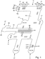
- Fig. 3 is illustrated in a somewhat simplified representation of how 17 flat sensor coils 35 are placed as inductive sensors for pot detection on the projection areas. They are advantageously glued, for example, with temperature-resistant silicone adhesive. Your electrical connection is described below with reference to Fig. 4 explained in more detail.
- the Fig. 4 shows a strong enlargement a projection portion 17 of the textile support member 13.
- Two conductor wires 31 lead left into the regions of the webs 20 between the recesses 19a to 19c. They are stapled with the stitching thread 32 shown here in a zigzag shape on the textile support member 13. Since the conductor wires 31 are advantageously not insulated, it is necessary to ensure a certain distance from each other, whereby a displacement by the stitching thread 32 is prevented.
- the conductor wires 31 lead up to the webs 20 and are stapled until shortly before.
- a temperature sensor 44 is placed here as the aforementioned THT component.
- the temperature sensor 44 has two connecting wire legs 45a and 45b, which are bent and also rest on the webs 20, where the ends of the two bare conductor wires 31 are located. Here they are electrically connected and mechanically fastened.
- Two further conductor wires 31 extend to the right on the webs 22 between the recesses 21a to 21c. They are also stapled with a stitching thread 32 except for the bare ends.
- a sensor coil accordingly Fig. 3 is shown here as a dot-dashed sensor coil 35 only partially. It has two outgoing connecting wires 36, whose free ends also overlap on the webs 22 between the recesses 21a to 21c. Because the sensor coils 35, like the Fig. 3 indicates, for example, in two layers of 10 to 20 turns exist, which are wound tightly to each other, the coil wire must be electrically isolated anyway or be provided with insulating varnish. The free ends of the connecting wires 36 are thereby freed from such insulating varnish or made bare.
- the Fig. 7 shows in the enlarged sectional view for explaining the connection technique, as above on the web 22 between the two recesses 21a and 21b both the conductor wire 31 and the lead wire 36 rest.
- a clamp 38 is now guided around this area and compressed, to which serve the two recesses 21a and 21b. Under certain circumstances, a single of these two recesses would be sufficient, but both the mechanical attachment and the electrical contact is advantageous and particularly safe in the manner shown.
- the clamp 38 could also be completely closed or bent over more than 360 °, but this need not be. It is advantageously made of bare metal such as brass for electrical contacting purposes. Their material is thick and strong enough that the clamp 38 does not bounce or deform easily after being bent or clamped together for a permanent connection.
- This technique has the advantage for use in an induction hob, that it is very temperature resistant, unlike, for example, soldering and especially the use of electrically conductive conductive adhesives. Furthermore, it can be carried out automatically.
- the connection of the connecting wire legs 45a and 45b of the temperature sensor 44 with the respective connecting wires 31 as electrical contacting as well as attachment to the textile carrier part 13 takes place as in FIG Fig. 7 shown.
- the temperature sensor 44 should lie in a free middle region of the sensor coil 35, as is the case Fig. 3 can be seen.
- the temperature sensor 44 may serve to determine at a particular location both the presence of an attached pot and the temperature conditions.
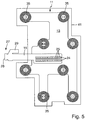
- Fig. 5 is the flexible carrier 11 made Fig. 3 shown on a micanite carrier 41 as the aforementioned flat rigid carrier. It can be laid or glued on, for example glued with heat-resistant silicone. Another flat rigid support in the form of a micanite support is placed thereon, so that a kind of sandwich construction is formed with the two rigid supports outside and the flexible support 11 in between.
- This assembly 40 is in the Fig. 8 shown in section, wherein it can be seen that the two micanite supports 41 and 42 are compressed so that the sensor coil 35 shown here at the bottom of the upper Micanite carrier 42 is applied. From the assembly 40 protrudes left of the connection carrier 15 with its free end 27 together with the connector 28 out.
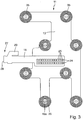
- Fig. 6 is shown as a structural unit 40 accordingly Fig. 8 placed on induction heating coils.
- the three induction coils 47a to 47c shown here are corresponding to the aforementioned DE 102014224051.4 formed approximately rectangular and have a corresponding approximately rectangular free middle region 48a to 48c.
- Some of the sensor coils 35 of the assembly 40 lie with their midpoint exactly between two Indu Vietnameseswespulen 47 adjacent to the longitudinal sides and overlap each a bit, such as the two uppermost sensor coils 35.
- Two sensor coils 35 are fully above the free middle portions 48b and 48c of the two lower Induction heating coils 47b and 47c.
- the two rightmost sensor coils 35 are fully over the turns of the induction heating coils 47b and 47c.
- This illustration is intended to illustrate that a unit 40 can be easily placed on the Indutechnischswespulen 47.
- the plug-in connection 28 at the free end region 27 projects in this case generally out of the assembly 40, so also here.
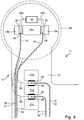
- FIG. 9 a section of an induction hob 50 according to the invention is shown, which has a conventional hob plate 51.
- An assembly 40 accordingly Fig. 8 is placed on an induction heating coil 47, advantageously on a plurality of such induction heating coils. These in turn rest on an inductor support 53, for example an aluminum sheet.
- the hob plate 51 is placed on it, so that there is a sandwich construction.
- the micanite carrier 41 and 42 on both sides of the flexible support 11 of this is protected from damage or impairment, for example, the stapled conductor wires 31.
- installation and electrical connection of a structural unit 40 as shown are very easy and safe and free of damage.
- FIG. 1 and 2 it is easy to imagine using the Fig. 1 and 2 in that another flexible carrier according to the invention in another embodiment either also has an originally separate connection carrier, which is then fastened to the textile carrier part, wherein the connection carrier also consists of a textile material.
- textile carrier part and connection carrier can also be produced, so to speak, in the area projection from a single part, so that they are not or were two separate parts.
- such a one-piece flexible support could also consist only of a flex circuit board or a conductor foil, in which case the many recesses with bars between them would still have to be provided, as at the aforementioned temperatures attachment and electrical contact of components or lead wires by means of soldering poses too many problems. This is just the benefit of being in the Fig. 7 Enlarged stapling technique or splicing technique.
- inductive sensors could be used instead of the flat sensor coils 35.
- capacitive sensor elements which may also be used for pot detection, such as the DE 102004016631 A1 to which reference is made in this regard.
Landscapes
- Engineering & Computer Science (AREA)
- Physics & Mathematics (AREA)
- Electromagnetism (AREA)
- Chemical & Material Sciences (AREA)
- Combustion & Propulsion (AREA)
- Mechanical Engineering (AREA)
- General Engineering & Computer Science (AREA)
- General Induction Heating (AREA)
- Induction Heating Cooking Devices (AREA)
Priority Applications (6)
| Application Number | Priority Date | Filing Date | Title |
|---|---|---|---|
| PL15163139T PL3079443T3 (pl) | 2015-04-10 | 2015-04-10 | Indukcyjna płyta grzejna i elastyczny nośnik dla indukcyjnej płyty grzejnej |
| ES15163139.7T ES2655815T3 (es) | 2015-04-10 | 2015-04-10 | Encimera de cocción por inducción y soporte flexible para una encimera de cocción por inducción |
| EP15163139.7A EP3079443B1 (de) | 2015-04-10 | 2015-04-10 | Induktionskochfeld und flexibler träger für ein induktionskochfeld |
| JP2016077445A JP6831641B2 (ja) | 2015-04-10 | 2016-04-07 | 誘導ホブ、及び誘導ホブのための可撓性の支持体 |
| CN201610215336.9A CN106051846B (zh) | 2015-04-10 | 2016-04-08 | 电磁炉和用于电磁炉的柔性支承件 |
| US15/094,616 US10271386B2 (en) | 2015-04-10 | 2016-04-08 | Induction hob and flexible support for an induction hob |
Applications Claiming Priority (1)
| Application Number | Priority Date | Filing Date | Title |
|---|---|---|---|
| EP15163139.7A EP3079443B1 (de) | 2015-04-10 | 2015-04-10 | Induktionskochfeld und flexibler träger für ein induktionskochfeld |
Publications (2)
| Publication Number | Publication Date |
|---|---|
| EP3079443A1 EP3079443A1 (de) | 2016-10-12 |
| EP3079443B1 true EP3079443B1 (de) | 2017-11-08 |
Family
ID=52823539
Family Applications (1)
| Application Number | Title | Priority Date | Filing Date |
|---|---|---|---|
| EP15163139.7A Active EP3079443B1 (de) | 2015-04-10 | 2015-04-10 | Induktionskochfeld und flexibler träger für ein induktionskochfeld |
Country Status (6)
| Country | Link |
|---|---|
| US (1) | US10271386B2 (pl) |
| EP (1) | EP3079443B1 (pl) |
| JP (1) | JP6831641B2 (pl) |
| CN (1) | CN106051846B (pl) |
| ES (1) | ES2655815T3 (pl) |
| PL (1) | PL3079443T3 (pl) |
Cited By (7)
| Publication number | Priority date | Publication date | Assignee | Title |
|---|---|---|---|---|
| US10605464B2 (en) | 2012-10-15 | 2020-03-31 | Whirlpool Corporation | Induction cooktop |
| US10893579B2 (en) | 2017-07-18 | 2021-01-12 | Whirlpool Corporation | Method for operating an induction cooking hob and cooking hob using such method |
| US10993292B2 (en) | 2017-10-23 | 2021-04-27 | Whirlpool Corporation | System and method for tuning an induction circuit |
| US11140751B2 (en) | 2018-04-23 | 2021-10-05 | Whirlpool Corporation | System and method for controlling quasi-resonant induction heating devices |
| US11212880B2 (en) | 2012-10-15 | 2021-12-28 | Whirlpool Emea S.P.A. | Induction cooking top |
| US12302478B2 (en) | 2018-04-23 | 2025-05-13 | Whirlpool Corporation | Control circuits and methods for distributed induction heating devices |
| US12588112B2 (en) | 2018-04-23 | 2026-03-24 | Whirlpool Corporation | System and method for controlling induction heating devices with series connected switching devices |
Families Citing this family (16)
| Publication number | Priority date | Publication date | Assignee | Title |
|---|---|---|---|---|
| DE102016223849B3 (de) | 2016-11-30 | 2018-05-09 | E.G.O. Elektro-Gerätebau GmbH | Kochfeld und Verfahren zum Betrieb eines solchen Kochfeldes |
| DE102016223848A1 (de) | 2016-11-30 | 2018-05-30 | E.G.O. Elektro-Gerätebau GmbH | Kochfeld und Verfahren zum Betrieb eines solchen Kochfeldes |
| DE102016225461B4 (de) | 2016-12-19 | 2024-12-24 | E.G.O. Elektro-Gerätebau GmbH | Kochfeld und Verfahren zum Betrieb eines solchen Kochfeldes |
| DE102017221341A1 (de) * | 2017-11-28 | 2019-05-29 | E.G.O. Elektro-Gerätebau GmbH | Topferkennungssensor für ein Induktionskochfeld und Induktionskochfeld |
| ES2736046A1 (es) | 2018-06-21 | 2019-12-23 | Bsh Electrodomesticos Espana Sa | Dispositivo de aparato de cocción |
| DE102020200694B4 (de) | 2020-01-22 | 2021-08-12 | E.G.O. Elektro-Gerätebau GmbH | Verfahren zum Betrieb einer Kochfeldvorrichtung und Kochfeldvorrichtung |
| ES2991859T3 (es) | 2020-01-22 | 2024-12-05 | Ego Elektro Geraetebau Gmbh | Método para controlar la potencia suministrada a una bobina de calentamiento por inducción de una encimera de cocción por inducción y encimera de cocción por inducción |
| DE102020201962B4 (de) | 2020-02-17 | 2022-06-09 | E.G.O. Elektro-Gerätebau GmbH | Kochfeld und Verfahren zum Betrieb eines Kochfelds |
| GB2593468B (en) * | 2020-03-23 | 2022-04-13 | Equip Line Ltd | An apparatus for heating a pot of food or beverage |
| US20230239974A1 (en) | 2020-07-01 | 2023-07-27 | BSH Hausgeräte GmbH | Induction cooking appliance |
| DE102020209648A1 (de) | 2020-07-30 | 2022-02-03 | E.G.O. Elektro-Gerätebau GmbH | Verfahren zum Betrieb eines Kochfelds und Kochfeld |
| CN115002945A (zh) * | 2021-03-01 | 2022-09-02 | 马勒国际有限公司 | 电加热设备 |
| USD1000205S1 (en) | 2021-03-05 | 2023-10-03 | Tramontina Teec S.A. | Cooktop or portion thereof |
| USD1000206S1 (en) | 2021-03-05 | 2023-10-03 | Tramontina Teec S.A. | Cooktop or portion thereof |
| DE102022205386A1 (de) | 2022-05-30 | 2023-11-30 | E.G.O. Elektro-Gerätebau GmbH | Induktionskochfeld mit einer Trägerstruktur mit Antennen und/oder Sensoren, Verfahren zur Herstellung einer solchen Trägerstruktur und eine Verwendung einer Trägerstruktur für ein Induktionskochfeld |
| DE102023109093B3 (de) | 2023-04-11 | 2024-08-08 | E.G.O. Elektro-Gerätebau GmbH | Sensorvorrichtung, Heizeinrichtung mit einer Sensorvorrichtung und Kochfeld mit mehreren Heizeinrichtungen |
Family Cites Families (8)
| Publication number | Priority date | Publication date | Assignee | Title |
|---|---|---|---|---|
| IT1272028B (it) * | 1993-03-15 | 1997-06-10 | Whirlpool Italia | Dispositivo per rilevare la presenza di un contenitore per alimenti, quale una pentola, una pirofila o similare, su un piano di cottura in vetroceramica. |
| US6184501B1 (en) * | 1999-09-23 | 2001-02-06 | Cherry Gmbh | Object detection system |
| DE102004016631A1 (de) | 2004-03-29 | 2005-11-10 | E.G.O. Elektro-Gerätebau GmbH | Vorrichtung und Verfahren zur Überwachung der Temperatur eines Kochgeschirrs auf einer Abdeckung eines Kochfeldes sowie von weiteren Vorgängen auf der Abdeckung |
| JP4839786B2 (ja) * | 2005-11-14 | 2011-12-21 | パナソニック株式会社 | 誘導加熱装置 |
| CN201014595Y (zh) * | 2007-03-20 | 2008-01-30 | 鹤山市威士达电器实业有限公司 | 一种带测温装置的电磁炉炊具 |
| ES2376566B1 (es) | 2009-10-13 | 2013-01-29 | Bsh Electrodomésticos España, S.A. | Campo de cocción con sensores inductivos. |
| CN201947486U (zh) * | 2011-01-21 | 2011-08-24 | 徐介东 | 一种电磁炉线圈盘装置 |
| EP2670211A3 (de) * | 2012-05-31 | 2014-08-13 | BSH Bosch und Siemens Hausgeräte GmbH | Kochfeldvorrichtung |
-
2015
- 2015-04-10 PL PL15163139T patent/PL3079443T3/pl unknown
- 2015-04-10 EP EP15163139.7A patent/EP3079443B1/de active Active
- 2015-04-10 ES ES15163139.7T patent/ES2655815T3/es active Active
-
2016
- 2016-04-07 JP JP2016077445A patent/JP6831641B2/ja not_active Expired - Fee Related
- 2016-04-08 US US15/094,616 patent/US10271386B2/en active Active
- 2016-04-08 CN CN201610215336.9A patent/CN106051846B/zh not_active Expired - Fee Related
Non-Patent Citations (1)
| Title |
|---|
| None * |
Cited By (10)
| Publication number | Priority date | Publication date | Assignee | Title |
|---|---|---|---|---|
| US10605464B2 (en) | 2012-10-15 | 2020-03-31 | Whirlpool Corporation | Induction cooktop |
| US11212880B2 (en) | 2012-10-15 | 2021-12-28 | Whirlpool Emea S.P.A. | Induction cooking top |
| US11655984B2 (en) | 2012-10-15 | 2023-05-23 | Whirlpool Corporation | Induction cooktop |
| US10893579B2 (en) | 2017-07-18 | 2021-01-12 | Whirlpool Corporation | Method for operating an induction cooking hob and cooking hob using such method |
| US10993292B2 (en) | 2017-10-23 | 2021-04-27 | Whirlpool Corporation | System and method for tuning an induction circuit |
| US12063731B2 (en) | 2017-10-23 | 2024-08-13 | Whirlpool Corporation | System and method for tuning an induction circuit |
| US11140751B2 (en) | 2018-04-23 | 2021-10-05 | Whirlpool Corporation | System and method for controlling quasi-resonant induction heating devices |
| US12245348B2 (en) | 2018-04-23 | 2025-03-04 | Whirlpool Corporation | System and method for controlling quasi-resonant induction heating devices |
| US12302478B2 (en) | 2018-04-23 | 2025-05-13 | Whirlpool Corporation | Control circuits and methods for distributed induction heating devices |
| US12588112B2 (en) | 2018-04-23 | 2026-03-24 | Whirlpool Corporation | System and method for controlling induction heating devices with series connected switching devices |
Also Published As
| Publication number | Publication date |
|---|---|
| US10271386B2 (en) | 2019-04-23 |
| JP2016201361A (ja) | 2016-12-01 |
| JP6831641B2 (ja) | 2021-02-17 |
| PL3079443T3 (pl) | 2018-04-30 |
| EP3079443A1 (de) | 2016-10-12 |
| CN106051846A (zh) | 2016-10-26 |
| CN106051846B (zh) | 2019-07-12 |
| ES2655815T3 (es) | 2018-02-21 |
| US20160302263A1 (en) | 2016-10-13 |
Similar Documents
| Publication | Publication Date | Title |
|---|---|---|
| EP3079443B1 (de) | Induktionskochfeld und flexibler träger für ein induktionskochfeld | |
| DE4131504C2 (de) | Federelement für eine Baugruppe eines elektronischen Steuergeräts | |
| EP1152639B1 (de) | Elektrische Heizeinheit, insbesondere für flüssige Medien | |
| DE1927008A1 (de) | Elektrischer oder elektronischer Einsteckbauteil fuer gedruckte Schaltungen | |
| WO2006032292A1 (de) | Heizungseinrichtung für eine flächige beheizung mit induktions-heizelementen | |
| EP2945463B1 (de) | Induktionskochfeld | |
| DE112014002583B4 (de) | Anschluss-versehener elektrischer Draht | |
| EP3592104B1 (de) | Beheizbare textil-vorrichtung | |
| DE202014003827U1 (de) | Heizeinrichtung mit einer dieser zugeordneten Temperaturerfassung zum Beheizen von Flächen im lnnenraum eines Fahrzeugs | |
| DE602004007496T2 (de) | Elektrisches widerstandsdraht-glimmerplattenheizelement, baugruppen, komponenten und montageverfahren | |
| EP3337291B1 (de) | Heizeinrichtung, kochgerät mit einer heizeinrichtung und verfahren zur herstellung eines heizelements | |
| DE4207638A1 (de) | Heizbare verbundglasscheibe mit in der thermoplastischen zwischenschicht angeordneten widerstandsdraehten | |
| DE69835197T2 (de) | Kochmulde mit topfanwesenheitserkennung | |
| EP1601235A2 (de) | Überwachungseinrichtung für flexible Heizelemente | |
| DE60308704T2 (de) | Vorrichtung zur Bestimmung der Position von Kochgefässen auf einer Kochplatte | |
| DE69405834T2 (de) | Elektrischer Wärmestrahler | |
| DE102014006623A1 (de) | Heizeinrichtung mit einer dieser zugeordneten Temperaturerfassung zum Beheizen von Flächen im lnnenraum eines Fahrzeugs | |
| WO2016037927A1 (de) | Elektromotor mit smd-bauteilen und zugehöriges verbindungsteil | |
| DE102009012627B4 (de) | Elektrisches Bauelement und Verfahren zum Reflow-Löten eines elektrischen Bauelements | |
| DE102017130508A1 (de) | Flexibler flächiger Heizer und Verfahren zu dessen Herstellung | |
| DE102017110060A1 (de) | Verfahren zum Herstellen einer Anordnung und Anordnung mit einer Stromschiene für eine Anschlussklemme zum Kontaktieren mehrerer elektrischer Leiter und elektrische Anschlussklemme | |
| DE102023109093B3 (de) | Sensorvorrichtung, Heizeinrichtung mit einer Sensorvorrichtung und Kochfeld mit mehreren Heizeinrichtungen | |
| EP2463589A1 (de) | Induktionskochfeld mit einer Kochplatte und einem unter der Kochplatte angeordneten Induktor | |
| DE2661101C2 (pl) | ||
| DE102017205061A1 (de) | Kochfeld |
Legal Events
| Date | Code | Title | Description |
|---|---|---|---|
| PUAI | Public reference made under article 153(3) epc to a published international application that has entered the european phase |
Free format text: ORIGINAL CODE: 0009012 |
|
| AK | Designated contracting states |
Kind code of ref document: A1 Designated state(s): AL AT BE BG CH CY CZ DE DK EE ES FI FR GB GR HR HU IE IS IT LI LT LU LV MC MK MT NL NO PL PT RO RS SE SI SK SM TR |
|
| AX | Request for extension of the european patent |
Extension state: BA ME |
|
| 17P | Request for examination filed |
Effective date: 20170201 |
|
| RBV | Designated contracting states (corrected) |
Designated state(s): AL AT BE BG CH CY CZ DE DK EE ES FI FR GB GR HR HU IE IS IT LI LT LU LV MC MK MT NL NO PL PT RO RS SE SI SK SM TR |
|
| REG | Reference to a national code |
Ref country code: DE Ref legal event code: R079 Ref document number: 502015002279 Country of ref document: DE Free format text: PREVIOUS MAIN CLASS: H05B0006060000 Ipc: H05B0006120000 |
|
| GRAP | Despatch of communication of intention to grant a patent |
Free format text: ORIGINAL CODE: EPIDOSNIGR1 |
|
| RIC1 | Information provided on ipc code assigned before grant |
Ipc: H05B 6/06 20060101ALI20170426BHEP Ipc: H05B 6/12 20060101AFI20170426BHEP |
|
| INTG | Intention to grant announced |
Effective date: 20170519 |
|
| GRAS | Grant fee paid |
Free format text: ORIGINAL CODE: EPIDOSNIGR3 |
|
| GRAA | (expected) grant |
Free format text: ORIGINAL CODE: 0009210 |
|
| AK | Designated contracting states |
Kind code of ref document: B1 Designated state(s): AL AT BE BG CH CY CZ DE DK EE ES FI FR GB GR HR HU IE IS IT LI LT LU LV MC MK MT NL NO PL PT RO RS SE SI SK SM TR |
|
| REG | Reference to a national code |
Ref country code: GB Ref legal event code: FG4D Free format text: NOT ENGLISH |
|
| REG | Reference to a national code |
Ref country code: CH Ref legal event code: EP Ref country code: AT Ref legal event code: REF Ref document number: 945315 Country of ref document: AT Kind code of ref document: T Effective date: 20171115 |
|
| REG | Reference to a national code |
Ref country code: IE Ref legal event code: FG4D Free format text: LANGUAGE OF EP DOCUMENT: GERMAN |
|
| REG | Reference to a national code |
Ref country code: DE Ref legal event code: R096 Ref document number: 502015002279 Country of ref document: DE |
|
| REG | Reference to a national code |
Ref country code: ES Ref legal event code: FG2A Ref document number: 2655815 Country of ref document: ES Kind code of ref document: T3 Effective date: 20180221 |
|
| REG | Reference to a national code |
Ref country code: NL Ref legal event code: MP Effective date: 20171108 |
|
| REG | Reference to a national code |
Ref country code: LT Ref legal event code: MG4D |
|
| REG | Reference to a national code |
Ref country code: FR Ref legal event code: PLFP Year of fee payment: 4 |
|
| PG25 | Lapsed in a contracting state [announced via postgrant information from national office to epo] |
Ref country code: LT Free format text: LAPSE BECAUSE OF FAILURE TO SUBMIT A TRANSLATION OF THE DESCRIPTION OR TO PAY THE FEE WITHIN THE PRESCRIBED TIME-LIMIT Effective date: 20171108 Ref country code: NL Free format text: LAPSE BECAUSE OF FAILURE TO SUBMIT A TRANSLATION OF THE DESCRIPTION OR TO PAY THE FEE WITHIN THE PRESCRIBED TIME-LIMIT Effective date: 20171108 Ref country code: SE Free format text: LAPSE BECAUSE OF FAILURE TO SUBMIT A TRANSLATION OF THE DESCRIPTION OR TO PAY THE FEE WITHIN THE PRESCRIBED TIME-LIMIT Effective date: 20171108 Ref country code: FI Free format text: LAPSE BECAUSE OF FAILURE TO SUBMIT A TRANSLATION OF THE DESCRIPTION OR TO PAY THE FEE WITHIN THE PRESCRIBED TIME-LIMIT Effective date: 20171108 Ref country code: NO Free format text: LAPSE BECAUSE OF FAILURE TO SUBMIT A TRANSLATION OF THE DESCRIPTION OR TO PAY THE FEE WITHIN THE PRESCRIBED TIME-LIMIT Effective date: 20180208 |
|
| PG25 | Lapsed in a contracting state [announced via postgrant information from national office to epo] |
Ref country code: IS Free format text: LAPSE BECAUSE OF FAILURE TO SUBMIT A TRANSLATION OF THE DESCRIPTION OR TO PAY THE FEE WITHIN THE PRESCRIBED TIME-LIMIT Effective date: 20180308 Ref country code: LV Free format text: LAPSE BECAUSE OF FAILURE TO SUBMIT A TRANSLATION OF THE DESCRIPTION OR TO PAY THE FEE WITHIN THE PRESCRIBED TIME-LIMIT Effective date: 20171108 Ref country code: GR Free format text: LAPSE BECAUSE OF FAILURE TO SUBMIT A TRANSLATION OF THE DESCRIPTION OR TO PAY THE FEE WITHIN THE PRESCRIBED TIME-LIMIT Effective date: 20180209 Ref country code: BG Free format text: LAPSE BECAUSE OF FAILURE TO SUBMIT A TRANSLATION OF THE DESCRIPTION OR TO PAY THE FEE WITHIN THE PRESCRIBED TIME-LIMIT Effective date: 20180208 Ref country code: HR Free format text: LAPSE BECAUSE OF FAILURE TO SUBMIT A TRANSLATION OF THE DESCRIPTION OR TO PAY THE FEE WITHIN THE PRESCRIBED TIME-LIMIT Effective date: 20171108 Ref country code: RS Free format text: LAPSE BECAUSE OF FAILURE TO SUBMIT A TRANSLATION OF THE DESCRIPTION OR TO PAY THE FEE WITHIN THE PRESCRIBED TIME-LIMIT Effective date: 20171108 |
|
| PG25 | Lapsed in a contracting state [announced via postgrant information from national office to epo] |
Ref country code: SK Free format text: LAPSE BECAUSE OF FAILURE TO SUBMIT A TRANSLATION OF THE DESCRIPTION OR TO PAY THE FEE WITHIN THE PRESCRIBED TIME-LIMIT Effective date: 20171108 Ref country code: CY Free format text: LAPSE BECAUSE OF FAILURE TO SUBMIT A TRANSLATION OF THE DESCRIPTION OR TO PAY THE FEE WITHIN THE PRESCRIBED TIME-LIMIT Effective date: 20171108 Ref country code: EE Free format text: LAPSE BECAUSE OF FAILURE TO SUBMIT A TRANSLATION OF THE DESCRIPTION OR TO PAY THE FEE WITHIN THE PRESCRIBED TIME-LIMIT Effective date: 20171108 Ref country code: DK Free format text: LAPSE BECAUSE OF FAILURE TO SUBMIT A TRANSLATION OF THE DESCRIPTION OR TO PAY THE FEE WITHIN THE PRESCRIBED TIME-LIMIT Effective date: 20171108 Ref country code: CZ Free format text: LAPSE BECAUSE OF FAILURE TO SUBMIT A TRANSLATION OF THE DESCRIPTION OR TO PAY THE FEE WITHIN THE PRESCRIBED TIME-LIMIT Effective date: 20171108 |
|
| REG | Reference to a national code |
Ref country code: DE Ref legal event code: R097 Ref document number: 502015002279 Country of ref document: DE |
|
| PG25 | Lapsed in a contracting state [announced via postgrant information from national office to epo] |
Ref country code: SM Free format text: LAPSE BECAUSE OF FAILURE TO SUBMIT A TRANSLATION OF THE DESCRIPTION OR TO PAY THE FEE WITHIN THE PRESCRIBED TIME-LIMIT Effective date: 20171108 |
|
| PLBE | No opposition filed within time limit |
Free format text: ORIGINAL CODE: 0009261 |
|
| STAA | Information on the status of an ep patent application or granted ep patent |
Free format text: STATUS: NO OPPOSITION FILED WITHIN TIME LIMIT |
|
| PG25 | Lapsed in a contracting state [announced via postgrant information from national office to epo] |
Ref country code: MT Free format text: LAPSE BECAUSE OF FAILURE TO SUBMIT A TRANSLATION OF THE DESCRIPTION OR TO PAY THE FEE WITHIN THE PRESCRIBED TIME-LIMIT Effective date: 20171108 |
|
| 26N | No opposition filed |
Effective date: 20180809 |
|
| PG25 | Lapsed in a contracting state [announced via postgrant information from national office to epo] |
Ref country code: MC Free format text: LAPSE BECAUSE OF FAILURE TO SUBMIT A TRANSLATION OF THE DESCRIPTION OR TO PAY THE FEE WITHIN THE PRESCRIBED TIME-LIMIT Effective date: 20171108 Ref country code: SI Free format text: LAPSE BECAUSE OF FAILURE TO SUBMIT A TRANSLATION OF THE DESCRIPTION OR TO PAY THE FEE WITHIN THE PRESCRIBED TIME-LIMIT Effective date: 20171108 |
|
| REG | Reference to a national code |
Ref country code: CH Ref legal event code: PL |
|
| REG | Reference to a national code |
Ref country code: BE Ref legal event code: MM Effective date: 20180430 |
|
| REG | Reference to a national code |
Ref country code: IE Ref legal event code: MM4A |
|
| PG25 | Lapsed in a contracting state [announced via postgrant information from national office to epo] |
Ref country code: LU Free format text: LAPSE BECAUSE OF NON-PAYMENT OF DUE FEES Effective date: 20180410 |
|
| PG25 | Lapsed in a contracting state [announced via postgrant information from national office to epo] |
Ref country code: CH Free format text: LAPSE BECAUSE OF NON-PAYMENT OF DUE FEES Effective date: 20180430 Ref country code: BE Free format text: LAPSE BECAUSE OF NON-PAYMENT OF DUE FEES Effective date: 20180430 Ref country code: LI Free format text: LAPSE BECAUSE OF NON-PAYMENT OF DUE FEES Effective date: 20180430 |
|
| PG25 | Lapsed in a contracting state [announced via postgrant information from national office to epo] |
Ref country code: IE Free format text: LAPSE BECAUSE OF NON-PAYMENT OF DUE FEES Effective date: 20180410 |
|
| PG25 | Lapsed in a contracting state [announced via postgrant information from national office to epo] |
Ref country code: PT Free format text: LAPSE BECAUSE OF FAILURE TO SUBMIT A TRANSLATION OF THE DESCRIPTION OR TO PAY THE FEE WITHIN THE PRESCRIBED TIME-LIMIT Effective date: 20171108 |
|
| PG25 | Lapsed in a contracting state [announced via postgrant information from national office to epo] |
Ref country code: RO Free format text: LAPSE BECAUSE OF FAILURE TO SUBMIT A TRANSLATION OF THE DESCRIPTION OR TO PAY THE FEE WITHIN THE PRESCRIBED TIME-LIMIT Effective date: 20171108 Ref country code: MK Free format text: LAPSE BECAUSE OF NON-PAYMENT OF DUE FEES Effective date: 20171108 Ref country code: HU Free format text: LAPSE BECAUSE OF FAILURE TO SUBMIT A TRANSLATION OF THE DESCRIPTION OR TO PAY THE FEE WITHIN THE PRESCRIBED TIME-LIMIT; INVALID AB INITIO Effective date: 20150410 |
|
| PG25 | Lapsed in a contracting state [announced via postgrant information from national office to epo] |
Ref country code: AL Free format text: LAPSE BECAUSE OF FAILURE TO SUBMIT A TRANSLATION OF THE DESCRIPTION OR TO PAY THE FEE WITHIN THE PRESCRIBED TIME-LIMIT Effective date: 20171108 |
|
| REG | Reference to a national code |
Ref country code: AT Ref legal event code: MM01 Ref document number: 945315 Country of ref document: AT Kind code of ref document: T Effective date: 20200410 |
|
| PG25 | Lapsed in a contracting state [announced via postgrant information from national office to epo] |
Ref country code: AT Free format text: LAPSE BECAUSE OF NON-PAYMENT OF DUE FEES Effective date: 20200410 |
|
| PGFP | Annual fee paid to national office [announced via postgrant information from national office to epo] |
Ref country code: GB Payment date: 20240423 Year of fee payment: 10 |
|
| PGFP | Annual fee paid to national office [announced via postgrant information from national office to epo] |
Ref country code: PL Payment date: 20250328 Year of fee payment: 11 |
|
| PGFP | Annual fee paid to national office [announced via postgrant information from national office to epo] |
Ref country code: DE Payment date: 20250417 Year of fee payment: 11 |
|
| PGFP | Annual fee paid to national office [announced via postgrant information from national office to epo] |
Ref country code: ES Payment date: 20250519 Year of fee payment: 11 |
|
| PGFP | Annual fee paid to national office [announced via postgrant information from national office to epo] |
Ref country code: IT Payment date: 20250430 Year of fee payment: 11 |
|
| PGFP | Annual fee paid to national office [announced via postgrant information from national office to epo] |
Ref country code: FR Payment date: 20250428 Year of fee payment: 11 |
|
| PGFP | Annual fee paid to national office [announced via postgrant information from national office to epo] |
Ref country code: TR Payment date: 20250404 Year of fee payment: 11 |
|
| GBPC | Gb: european patent ceased through non-payment of renewal fee |
Effective date: 20250410 |
|
| PG25 | Lapsed in a contracting state [announced via postgrant information from national office to epo] |
Ref country code: GB Free format text: LAPSE BECAUSE OF NON-PAYMENT OF DUE FEES Effective date: 20250410 |