EP3077226B1 - Suspension arm for a motor vehicle intended to absorb a side impact - Google Patents
Suspension arm for a motor vehicle intended to absorb a side impact Download PDFInfo
- Publication number
- EP3077226B1 EP3077226B1 EP14805598.1A EP14805598A EP3077226B1 EP 3077226 B1 EP3077226 B1 EP 3077226B1 EP 14805598 A EP14805598 A EP 14805598A EP 3077226 B1 EP3077226 B1 EP 3077226B1
- Authority
- EP
- European Patent Office
- Prior art keywords
- branch
- vehicle
- curvature
- edge
- arm
- Prior art date
- Legal status (The legal status is an assumption and is not a legal conclusion. Google has not performed a legal analysis and makes no representation as to the accuracy of the status listed.)
- Active
Links
- 239000000725 suspension Substances 0.000 title claims description 21
- 229910000831 Steel Inorganic materials 0.000 claims description 3
- 239000010959 steel Substances 0.000 claims description 3
- 230000006835 compression Effects 0.000 description 2
- 238000007906 compression Methods 0.000 description 2
- 230000000284 resting effect Effects 0.000 description 2
- 238000000926 separation method Methods 0.000 description 2
- 238000010521 absorption reaction Methods 0.000 description 1
- 239000000463 material Substances 0.000 description 1
- 230000035939 shock Effects 0.000 description 1
Images
Classifications
-
- B—PERFORMING OPERATIONS; TRANSPORTING
- B60—VEHICLES IN GENERAL
- B60G—VEHICLE SUSPENSION ARRANGEMENTS
- B60G7/00—Pivoted suspension arms; Accessories thereof
- B60G7/001—Suspension arms, e.g. constructional features
-
- F—MECHANICAL ENGINEERING; LIGHTING; HEATING; WEAPONS; BLASTING
- F16—ENGINEERING ELEMENTS AND UNITS; GENERAL MEASURES FOR PRODUCING AND MAINTAINING EFFECTIVE FUNCTIONING OF MACHINES OR INSTALLATIONS; THERMAL INSULATION IN GENERAL
- F16F—SPRINGS; SHOCK-ABSORBERS; MEANS FOR DAMPING VIBRATION
- F16F1/00—Springs
- F16F1/36—Springs made of rubber or other material having high internal friction, e.g. thermoplastic elastomers
- F16F1/3615—Springs made of rubber or other material having high internal friction, e.g. thermoplastic elastomers with means for modifying the spring characteristic
-
- F—MECHANICAL ENGINEERING; LIGHTING; HEATING; WEAPONS; BLASTING
- F16—ENGINEERING ELEMENTS AND UNITS; GENERAL MEASURES FOR PRODUCING AND MAINTAINING EFFECTIVE FUNCTIONING OF MACHINES OR INSTALLATIONS; THERMAL INSULATION IN GENERAL
- F16F—SPRINGS; SHOCK-ABSORBERS; MEANS FOR DAMPING VIBRATION
- F16F1/00—Springs
- F16F1/36—Springs made of rubber or other material having high internal friction, e.g. thermoplastic elastomers
- F16F1/371—Springs made of rubber or other material having high internal friction, e.g. thermoplastic elastomers characterised by inserts or auxiliary extension or exterior elements, e.g. for rigidification
- F16F1/3713—Springs made of rubber or other material having high internal friction, e.g. thermoplastic elastomers characterised by inserts or auxiliary extension or exterior elements, e.g. for rigidification with external elements passively influencing spring stiffness, e.g. rings or hoops
-
- B—PERFORMING OPERATIONS; TRANSPORTING
- B60—VEHICLES IN GENERAL
- B60G—VEHICLE SUSPENSION ARRANGEMENTS
- B60G2200/00—Indexing codes relating to suspension types
- B60G2200/10—Independent suspensions
- B60G2200/14—Independent suspensions with lateral arms
- B60G2200/142—Independent suspensions with lateral arms with a single lateral arm, e.g. MacPherson type
- B60G2200/1424—Independent suspensions with lateral arms with a single lateral arm, e.g. MacPherson type the lateral arm having an L-shape
-
- B—PERFORMING OPERATIONS; TRANSPORTING
- B60—VEHICLES IN GENERAL
- B60G—VEHICLE SUSPENSION ARRANGEMENTS
- B60G2204/00—Indexing codes related to suspensions per se or to auxiliary parts
- B60G2204/10—Mounting of suspension elements
- B60G2204/14—Mounting of suspension arms
- B60G2204/143—Mounting of suspension arms on the vehicle body or chassis
- B60G2204/1431—Mounting of suspension arms on the vehicle body or chassis of an L-shaped arm
-
- B—PERFORMING OPERATIONS; TRANSPORTING
- B60—VEHICLES IN GENERAL
- B60G—VEHICLE SUSPENSION ARRANGEMENTS
- B60G2206/00—Indexing codes related to the manufacturing of suspensions: constructional features, the materials used, procedures or tools
- B60G2206/01—Constructional features of suspension elements, e.g. arms, dampers, springs
- B60G2206/016—Constructional features of suspension elements, e.g. arms, dampers, springs allowing controlled deformation during collision
-
- B—PERFORMING OPERATIONS; TRANSPORTING
- B60—VEHICLES IN GENERAL
- B60G—VEHICLE SUSPENSION ARRANGEMENTS
- B60G2206/00—Indexing codes related to the manufacturing of suspensions: constructional features, the materials used, procedures or tools
- B60G2206/01—Constructional features of suspension elements, e.g. arms, dampers, springs
- B60G2206/10—Constructional features of arms
- B60G2206/122—Constructional features of arms the arm having L-shape
-
- F—MECHANICAL ENGINEERING; LIGHTING; HEATING; WEAPONS; BLASTING
- F16—ENGINEERING ELEMENTS AND UNITS; GENERAL MEASURES FOR PRODUCING AND MAINTAINING EFFECTIVE FUNCTIONING OF MACHINES OR INSTALLATIONS; THERMAL INSULATION IN GENERAL
- F16F—SPRINGS; SHOCK-ABSORBERS; MEANS FOR DAMPING VIBRATION
- F16F7/00—Vibration-dampers; Shock-absorbers
- F16F7/12—Vibration-dampers; Shock-absorbers using plastic deformation of members
Definitions
- the invention relates to the field of motor vehicles and more particularly to the suspension of these vehicles.
- the subject of the invention is more particularly a suspension arm for a motor vehicle comprising a first branch intended to be connected to a wheel support of the vehicle, and a second branch intended to be mounted on the chassis of the vehicle.
- Another object of the present invention is a vehicle including at least one suspension arm as described.
- Motor vehicles are generally equipped with several transverse suspension arms which each comprise a first branch intended to be connected to a wheel support of the vehicle, in particular a knuckle holder, and a second branch intended to be mounted on the vehicle frame, in particular. the cradle of the vehicle when talking about the front wheel.
- the front suspension arms are stressed during shocks applied to the corresponding wheel according to a range of angles ranging from purely longitudinal impact to the vehicle to purely transverse impact to the vehicle. They are generally too fusible in the event of longitudinal or oblique impacts (failure forces too low) and are too resistant in pure transverse impact, causing deformations either of the cradle (involving a high cost repair) or of the knuckle holder (case failure difficult to detect).
- the aim of the present invention is to provide a solution allowing a certain fusibility of a vehicle suspension arm, in particular during a transverse impact with the vehicle.
- the first branch is shaped so that its general profile comprises, between a zone of connection to the wheel support and a zone of connection of the first branch to the second branch, a curvature essentially included in a vertical plane when the arm is mounted on the vehicle.
- the curvature is shaped so as to create a preferential zone of deformation, or rupture, of the first branch in the event of a transverse impact to the vehicle on its wheel in order to absorb at least part of the energy of said impact.
- the arm comprises a first curved line and at least part of a first edge of the first branch extends the along said first curved line, said first edge being disposed on the front side of the vehicle when the arm is mounted on the vehicle.
- the first branch has a second edge opposite the first edge along the longitudinal axis of the vehicle and disposed on the rear side of the vehicle when the arm is mounted on the vehicle, the second edge being included in a first plane including the two opposite longitudinal ends of the first branch and / or two longitudinal edges of the second branch, said first plane being substantially perpendicular to a second plane including the first curved line.
- the curvature has a second curved line
- the first branch has a second edge, opposite the first edge along the longitudinal axis of the vehicle and disposed on the rear side of the vehicle when the arm is mounted on the vehicle, s 'extending along the second curved line, said first and second edges being connected by a connecting portion of the first branch.
- the connecting part evolves along a curvature surface of the first branch including the first and second curved lines.
- the first and second curved lines are different.
- the curvature presents, along the length of the first branch, a sinusoidal profile, or an arcuate profile, in particular without a point of inflection.
- the invention also relates to a motor vehicle comprising at least one arm as described.
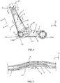
- the suspension arm for a motor vehicle (also called lateral suspension arm in the field) comprises a first branch 1 intended to be connected to a wheel support of the vehicle, in particular a knuckle holder, and a second branch 2 intended to be mounted to the chassis of the vehicle, in particular to the engine cradle of the vehicle.
- the first branch 1 is shaped so that its general profile comprises, between a zone of connection Z1 to the wheel support and a zone of connection Z2 of the first branch 1 to the second branch 2, a curvature essentially included in a vertical plane when the arm is mounted on the vehicle.
- an element for mounting the first branch 1 to the wheel support can be coupled to a first end E1 of the first branch 1 arranged at the level of the connection zone Z1.
- the arm can be connected to the frame via two openings 100a and 100b intended to be associated with suitable mounting elements.
- the opening 100a is located at the level of a second end E2 of the first branch 1, said second end E2 being located at the level of the connection zone Z2.
- the first and second ends E1, E2 of the first branch 1 are opposite longitudinal ends of the latter.
- the openings 100a and 100b are respectively formed at two opposite longitudinal ends of the second branch 2, one of the longitudinal ends of which coincides with the second end E2 of the first branch 1.
- the curvature is present at least in a central zone of the first branch 1 located equidistant from the connection zone Z1 and from the connection zone Z2.
- first branch 1 is defined between a lower face and an upper face such that said lower and upper faces follow the evolution of a virtual curved surface, in particular median, disposed between the faces. lower and upper. In certain cases, this median virtual surface defines a surface of symmetry of the first branch 1 between its lower and upper faces.
- the lower face is the one facing the ground and the upper face the one facing the sky.
- the curvature 3 is such that the first branch 1 has a concavity oriented towards the ground when the arm is mounted on a vehicle.
- the concavity can also be oriented towards the sky when the arm is mounted on a vehicle.
- the orientation of the concavity can be determined as a function of the architecture of the vehicle and in particular of the space available to house the suspension arm.
- curvature essentially included in a vertical plane is meant that the curvature has three-dimensional components and that the vertical component Z is greater than the X and Y components.
- the axis X is a longitudinal axis of the vehicle passing through the front and through the rear of the vehicle, and the arrow of which is oriented towards the front of the vehicle.
- the Y axis is for its part an axis transverse to the vehicle and perpendicular to the X axis.
- the XY frame represents a horizontal plane of the vehicle when it is resting on its wheels on horizontal ground.
- the Z axis is an axis perpendicular to the X and Y axes, and is a vertical axis to the vehicle, the arrow of which is oriented towards the sky when the vehicle is resting on its wheels.
- These Y, X and Z axes are taken from figures 1 to 4 and 6 to represent an advantageous positioning of the various elements represented within a motor vehicle.
- the word "axis" may be replaced by the word "component”.
- the curvature 3 evolving in a vertical direction makes it possible to reduce the compressive strength in the event of a side impact to the vehicle at the level of the wheel support.
- the curvature 3 is shaped so as to create a preferential zone of deformation, or breakage, of the first branch 1 in the event of a transverse impact to the vehicle on its wheel with a view to at least partially absorbing the energy of said impact.
- a curvature can be defined according to a curvature surface delimited by a plurality of curved lines.
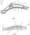
- the curvature 3 comprises a first curved line l 1 (visible at figures 2 to 4 ) and at least part (or even all) of a first edge 4 ( figures 1 to 4 ) of the first branch 1 extends along said first curved line l 1 (included in the plane P2 perpendicular to the plane of the figure 1 ), said first edge 4 being disposed on the front side of the vehicle when the arm is mounted on the vehicle.
- the curvature 3 comprises a second curved line l 2 and the first branch 1 comprises a second edge 5, opposite the first edge along the longitudinal axis X of the vehicle and disposed on the rear side of the vehicle when the arm is mounted on the vehicle. At least part of the (or even all of the) second edge extends along the second curved line l 2 , said first and second edges 4, 5 being connected by a connecting part 6 of the first branch 1.
- the second curved line l 2 is included in a plane P3 perpendicular to the plane of the figure 1 .
- the plane P3 passes through the connection zone Z1 and the connection zone Z2 and may intersect with the plane P2.
- the first curved line l 1 (and therefore the first associated curved edge 4) has a depth of concavity of 17mm
- the second curved line l 2 (and therefore the associated second curved edge 5) has a concavity depth of 10mm
- the depth of concavity associated with the first edge 4 is the maximum distance d 1 of separation of the first edge 4 with respect to the plane P1 on which the two opposite longitudinal ends of said first edge 4 rest.
- the depth of concavity associated with the second edge 5 is the maximum distance d 2 of separation of the second edge 5 with respect to the plane P1 on which the two opposite longitudinal ends of said second edge 5 rest.
- the curvature 3 can be limited between the first curved line l 1 and the second curved line l 2 .
- the connecting part 6 evolves along a surface of curvature of the first branch 1 including the first and second curved lines.
- the first and second curved lines l 1 , l 2 are different.
- the curvature of the first branch 1 at the level of the first line l 1 is greater than the curvature of the first branch 1 at the level of the second curved line l 2 .
- the difference in curvature between the first and second curved lines allows in particular an easier ruin during a transverse impact to the vehicle and applied to said arm when it is mounted on the vehicle while maintaining an optimal configuration of the holding of the arm in longitudinal impact to the vehicle.
- the first branch 1 comprises a second edge 5 opposite the first edge 4 along the longitudinal axis X of the vehicle and disposed on the rear side of the vehicle when the arm is mounted on the vehicle, the second edge being included in a first plane P1 including the two opposite longitudinal ends E1, E2 of the first branch 1 and / or two longitudinal edges 7, 8 of the second branch 2, said first plane P1 being substantially perpendicular to a second plane P2 (perpendicular to the plane of the figure 1 which constitutes the plane P1) including the first curved line l 1 .
- the first edge 4 works in traction in oblique impact on the vehicle so as to remain stable just like the second edge 5.
- the first edge 4 then works in compression and becomes unstable again to trigger the ruin of the arm.
- the second edge 5 can be elongated between the two ends E1 and E2 of the first branch 1 while remaining straight (that is to say not curved) while the first edge 4 is curved.
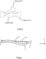
- This is particularly illustrated by the cross-sections along BB, CC and DD of the arm of the figure 1 conformed according to the second embodiment and superimposed on each other at the figure 5 .
- the connecting part 6 of the first branch is shaped so as to adapt from a planar component of the second edge 5 to a curved component of the first edge 4.
- the first embodiment allows easier deformation in the event of a side impact with the vehicle than the second embodiment.
- the curvature 3 has, along the length of the first branch 1, a sinusoidal profile, or an arcuate profile, in particular without a point of inflection. More particularly, the first curved line and / or the second curved line is a sinusoidal line (in particular an S-shaped line), or arched in particular without an inflection point (in particular a banana-shaped line).
- the particular example of the figure 6 is representative of a first branch, the first edge of which is curved along a sinusoidal curved line while the second edge remains straight.
- the profile, or sinusoidal line makes it possible to facilitate the compression of the arm in the event of a side impact to the vehicle equipped with said arm at the level of the wheel support.
- the arm can be formed from a single sheet, from forged material, from a two-shell, etc.
- the suspension arm can be formed as a monolithic piece.
- At least the first branch is made of forged steel.
- the suspension arm can also be entirely in forged steel.
- the invention also relates to a motor vehicle, comprising at least one arm as described above.
- the arm is used as a side suspension arm as part of a Macpherson suspension. It will then be understood that the suspension arm can be applied to any type of train comprising a suspension arm.
Description
L'invention concerne le domaine des véhicules automobile et plus particulièrement la suspension de ces véhiculesThe invention relates to the field of motor vehicles and more particularly to the suspension of these vehicles.
L'invention a pour objet plus particulièrement un bras de suspension pour véhicule automobile comprenant une première branche destinée à être raccordée à un support de roue du véhicule, et une deuxième branche destinée à être montée au châssis du véhiculeThe subject of the invention is more particularly a suspension arm for a motor vehicle comprising a first branch intended to be connected to a wheel support of the vehicle, and a second branch intended to be mounted on the chassis of the vehicle.
Un autre objet de la présente invention est un véhicule incluant au moins un bras de suspension tel que décrit.Another object of the present invention is a vehicle including at least one suspension arm as described.
Un exemple d'un tel bras de suspension est divulgué par
Les véhicules automobiles sont en général équipés de plusieurs bras de suspension transversaux qui comportent chacun une première branche destinée à être raccordée à un support de roue du véhicule, notamment un porte fusée, et une deuxième branche destinée à être montée au châssis du véhicule, notamment le berceau du véhicule lorsque l'on parle de la roue avant.Motor vehicles are generally equipped with several transverse suspension arms which each comprise a first branch intended to be connected to a wheel support of the vehicle, in particular a knuckle holder, and a second branch intended to be mounted on the vehicle frame, in particular. the cradle of the vehicle when talking about the front wheel.
Les bras de suspension avant sont sollicités lors de chocs appliqués à la roue correspondante selon une palette d'angles allant du choc purement longitudinal au véhicule au choc purement transversal au véhicule. Ils sont en général trop fusibles en cas de chocs longitudinaux ou obliques (efforts de ruine trop faibles) et sont trop résistants en choc transversal pur, engendrant des déformations soit du berceau (impliquant une réparation à coût élevé), soit du porte fusée (cas de défaillance difficile à détecter).The front suspension arms are stressed during shocks applied to the corresponding wheel according to a range of angles ranging from purely longitudinal impact to the vehicle to purely transverse impact to the vehicle. They are generally too fusible in the event of longitudinal or oblique impacts (failure forces too low) and are too resistant in pure transverse impact, causing deformations either of the cradle (involving a high cost repair) or of the knuckle holder (case failure difficult to detect).
Le but de la présente invention est de proposer une solution permettant une certaine fusibilité d'un bras de suspension de véhicule, notamment lors d'un choc transversal au véhicule.The aim of the present invention is to provide a solution allowing a certain fusibility of a vehicle suspension arm, in particular during a transverse impact with the vehicle.
On tend vers ce but notamment en ce que la première branche est conformée de sorte que son profil général comporte, entre une zone de raccordement au support de roue et une zone de raccordement de la première branche à la deuxième branche, une courbure essentiellement comprise dans un plan vertical lorsque le bras est monté sur le véhicule.We tend towards this goal in particular in that the first branch is shaped so that its general profile comprises, between a zone of connection to the wheel support and a zone of connection of the first branch to the second branch, a curvature essentially included in a vertical plane when the arm is mounted on the vehicle.
Selon l'invention, la courbure est conformée de telle sorte à créer une zone préférentielle de déformation, ou de rupture, de la première branche en cas d'impact transversal au véhicule sur sa roue en vue d'absorber au moins en partie l'énergie dudit impact.According to the invention, the curvature is shaped so as to create a preferential zone of deformation, or rupture, of the first branch in the event of a transverse impact to the vehicle on its wheel in order to absorb at least part of the energy of said impact.
Selon l'invention, le bras comporte une première ligne courbe et au moins une partie d'un premier bord de la première branche s'étend le long de ladite première ligne courbe, ledit premier bord étant disposé du côté avant du véhicule lorsque le bras est monté sur le véhicule.According to the invention, the arm comprises a first curved line and at least part of a first edge of the first branch extends the along said first curved line, said first edge being disposed on the front side of the vehicle when the arm is mounted on the vehicle.
La première branche comporte un deuxième bord opposé au premier bord selon l'axe longitudinal du véhicule et disposé du côté arrière du véhicule lorsque le bras est monté sur le véhicule, le deuxième bord étant inclus dans un premier plan incluant les deux extrémités longitudinales opposée de la première branche et/ou deux bords longitudinaux de la deuxième branche, ledit premier plan étant sensiblement perpendiculaire à un deuxième plan incluant la première ligne courbe.The first branch has a second edge opposite the first edge along the longitudinal axis of the vehicle and disposed on the rear side of the vehicle when the arm is mounted on the vehicle, the second edge being included in a first plane including the two opposite longitudinal ends of the first branch and / or two longitudinal edges of the second branch, said first plane being substantially perpendicular to a second plane including the first curved line.
Selon l'invention, la courbure comporte une deuxième ligne courbe, et la première branche comporte un deuxième bord, opposé au premier bord selon l'axe longitudinal du véhicule et disposé du côté arrière du véhicule lorsque le bras est monté sur le véhicule, s'étendant le long de la deuxième ligne courbe, lesdits premier et deuxième bords étant reliés par une partie de liaison de la première branche.According to the invention, the curvature has a second curved line, and the first branch has a second edge, opposite the first edge along the longitudinal axis of the vehicle and disposed on the rear side of the vehicle when the arm is mounted on the vehicle, s 'extending along the second curved line, said first and second edges being connected by a connecting portion of the first branch.
Selon l'invention, la courbure étant bornée entre la première ligne courbe et la deuxième ligne courbe, la partie de liaison évolue selon une surface de courbure de la première branche incluant les première et deuxième lignes courbes.According to the invention, the curvature being limited between the first curved line and the second curved line, the connecting part evolves along a curvature surface of the first branch including the first and second curved lines.
Les première et deuxième lignes courbes sont différentes.The first and second curved lines are different.
Selon une variante, la courbure présente selon la longueur de la première branche, un profil sinusoïdal, ou un profil arqué notamment sans point d'inflexion.According to one variant, the curvature presents, along the length of the first branch, a sinusoidal profile, or an arcuate profile, in particular without a point of inflection.
L'invention est aussi relative à un véhicule automobile comportant au moins un bras tel que décrit.The invention also relates to a motor vehicle comprising at least one arm as described.
D'autres avantages et caractéristiques ressortiront plus clairement de la description qui va suivre de modes particuliers de réalisation de l'invention donnés à titre d'exemples non limitatifs et représentés sur les dessins annexés, dans lesquels :
- la
figure 1 est une vue de dessus d'un bras de suspension selon une réalisation particulière de l'invention, - la
figure 2 est une vue d'un mode de réalisation particulier de lafigure 1 selon la vue A-A, - la
figure 3 est une vue en perspective de lafigure 1 selon le mode de réalisation particulier de lafigure 2 , - la
figure 4 est une vue d'un autre mode de réalisation particulier de lafigure 1 selon la vue A-A, - la
figure 5 illustre ledit autre mode de réalisation particulier de lafigure 4 par superposition des coupes B-B, C-C et D-D de lafigure 1 , - la
figure 6 illustre une variante de réalisation de la courbure appliquée au mode de réalisation de lafigure 4 .
- the
figure 1 is a top view of a suspension arm according to a particular embodiment of the invention, - the
figure 2 is a view of a particular embodiment of thefigure 1 according to view AA, - the
figure 3 is a perspective view of thefigure 1 according to the particular embodiment of thefigure 2 , - the
figure 4 is a view of another particular embodiment of thefigure 1 according to view AA, - the
figure 5 illustrates said other particular embodiment of thefigure 4 by superimposing the sections BB, CC and DD of thefigure 1 , - the
figure 6 illustrates an alternative embodiment of the curvature applied to the embodiment of thefigure 4 .
Le bras de suspension décrit ci-après permet, grâce à son profil, de faciliter l'absorption d'un choc latéral au véhicule équipé dudit bras. Comme illustré à la
En fait, un élément de montage de la première branche 1 au support de roue peut être accouplé à une première extrémité E1 de la première branche 1 disposée au niveau de la zone de raccordement Z1. Le bras peut être raccordé au châssis via deux ouvertures 100a et 100b destinées à être associées à des éléments de montage adaptés. L'ouverture 100a est située au niveau d'une deuxième extrémité E2 de la première branche 1, ladite deuxième extrémité E2 étant située au niveau de la zone de raccordement Z2. Les première et deuxième extrémités E1, E2 de la première branche 1 sont des extrémités longitudinales opposées de cette dernière. Les ouvertures 100a et 100b sont respectivement formées à deux extrémités longitudinales opposées de la deuxième branche 2 dont l'une des extrémités longitudinales coïncide avec la deuxième extrémité E2 de la première branche 1.In fact, an element for mounting the
Selon l'invention, la courbure est présente au moins dans une zone centrale de la première branche 1 située à équidistance de la zone de raccordement Z1 et de la zone de raccordement Z2.According to the invention, the curvature is present at least in a central zone of the
Cette courbure n'est pas visible à la
Par « profil général », on entend que la première branche 1 est définie entre une face inférieure et une face supérieure de telle sorte que lesdites faces inférieure et supérieure suivent l'évolution d'une surface courbée virtuelle, notamment médiane, disposée entre les faces inférieure et supérieure. Dans certain cas, cette surface virtuelle médiane définit une surface de symétrie de la première branche 1 entre ses faces inférieure et supérieure. Lorsque le bras est monté sur le véhicule, la face inférieure est celle orientée vers le sol et la face supérieure celle orientée vers le ciel.The term “general profile” is understood to mean that the
De préférence, la courbure 3 est telle que la première branche 1 présente une concavité orientée vers le sol lorsque le bras est monté sur un véhicule. Alternativement, la concavité peut aussi être orientée vers le ciel lorsque le bras est monté sur un véhicule. En fait, l'orientation de la concavité peut être déterminée en fonction de l'architecture du véhicule et notamment de la place disponible pour loger le bras de suspension.Preferably, the
Par « courbure essentiellement comprise dans un plan vertical » on entend que la courbure présente des composantes tridimensionnelles et que la composante verticale Z est supérieure aux composantes X et Y. Par convention, dans la présente description, l'axe X est un axe longitudinal du véhicule passant par l'avant et par l'arrière du véhicule, et dont la flèche est orientée vers l'avant du véhicule. L'axe Y est quant à lui un axe transversal au véhicule et perpendiculaire à l'axe X. Le repère XY représente un plan horizontal du véhicule lorsqu'il repose sur ses roues sur un sol horizontal. L'axe Z est un axe perpendiculaire aux axes X et Y, et est un axe vertical au véhicule dont la flèche est orientée vers le ciel lorsque le véhicule repose sur ses roues. Ces axes Y, X et Z sont repris aux
En fait, la courbure 3 évoluant selon une direction verticale permet d'amoindrir la résistance en compression en cas de choc latéral au véhicule au niveau du support de roue. Autrement dit, la courbure 3 est conformée de telle sorte à créer une zone préférentielle de déformation, ou de rupture, de la première branche 1 en cas d'impact transversal au véhicule sur sa roue en vue d'absorber au moins en partie l'énergie dudit impact.In fact, the
Une courbure peut être définie selon une surface de courbure délimitée par une pluralité de lignes courbes.A curvature can be defined according to a curvature surface delimited by a plurality of curved lines.
En ce sens, la courbure 3 comporte une première ligne courbe l1 (visible aux
Par « s'étendre le long d'une ligne courbe », on entend que le bord correspondant adopte une forme extérieure courbée sensiblement (ou exactement) selon la courbure de ladite ligne courbe.By "extend along a curved line" is meant that the corresponding edge adopts an outer shape curved substantially (or exactly) according to the curvature of said curved line.
Selon une première réalisation donnée dans l'exemple des
Selon un exemple particulier associé à la première réalisation la première ligne courbe l1 (et donc le premier bord 4 courbé associé) présente une profondeur de concavité de 17mm, et la deuxième ligne courbe l2 (et donc le deuxième bord 5 courbé associé) présente une profondeur de concavité de 10mm. Sur la
On comprend des
Les première et deuxième lignes courbes l1, l2 sont différentes.The first and second curved lines l 1 , l 2 are different.
Dans l'exemple de la
La différence de courbure entre les première et deuxième lignes courbes permet notamment une ruine plus aisée lors d'un choc transversal au véhicule et appliqué sur ledit bras lorsqu'il est monté sur le véhicule tout en conservant une configuration optimale de la tenue du bras en choc longitudinal au véhicule.The difference in curvature between the first and second curved lines allows in particular an easier ruin during a transverse impact to the vehicle and applied to said arm when it is mounted on the vehicle while maintaining an optimal configuration of the holding of the arm in longitudinal impact to the vehicle.
Selon une deuxième réalisation illustrée aux
Autrement dit, on comprend que le deuxième bord 5 peut être allongé entre les deux extrémités E1 et E2 de la première branche 1 tout en restant droit (c'est-à-dire non courbé) tandis que premier bord 4 est courbé. Ceci est notamment illustré par les coupes selon B-B, C-C et D-D du bras de la
La première réalisation permet une déformation plus aisée en cas de choc latéral au véhicule que la deuxième réalisation.The first embodiment allows easier deformation in the event of a side impact with the vehicle than the second embodiment.
De manière générale applicable à tout ce qui a été dit ci-dessus, la courbure 3 présente selon la longueur de la première branche 1, un profil sinusoïdal, ou un profil arqué notamment sans point d'inflexion. Plus particulièrement, la première ligne courbe et/ou la deuxième ligne courbe est une ligne sinusoïdale (notamment une ligne de forme en S), ou arquée notamment sans point d'inflexion (notamment une ligne en forme de banane).Generally applicable to everything that has been said above, the
L'exemple particulier de la
Le profil, ou ligne sinusoïdale permet de faciliter la compression du bras en cas de choc latéral au véhicule équipé dudit bras au niveau du support de roue.The profile, or sinusoidal line, makes it possible to facilitate the compression of the arm in the event of a side impact to the vehicle equipped with said arm at the level of the wheel support.
De manière générale applicable à tout ce qui a été dit ci-dessus, le bras peut être formé en mono-tôle, en matière forgée, d'une bi-coquille, etc.Generally applicable to everything that has been said above, the arm can be formed from a single sheet, from forged material, from a two-shell, etc.
Le bras de suspension peut être formé en une pièce monolithique.The suspension arm can be formed as a monolithic piece.
Selon l'invention, au moins la première branche est en acier forgé. Bien entendu, le bras de suspension peut aussi être intégralement en acier forgé.According to the invention, at least the first branch is made of forged steel. Of course, the suspension arm can also be entirely in forged steel.
Bien entendu, l'invention est aussi relative à un véhicule automobile, comportant au moins un bras tel que décrit précédemment. En particulier le bras est utilisé en tant que bras latéral de suspension dans le cadre d'une suspension Macpherson. On comprend alors que le bras de suspension peut s'appliquer à tout type de train comprenant un bras de suspension.Of course, the invention also relates to a motor vehicle, comprising at least one arm as described above. In particular the arm is used as a side suspension arm as part of a Macpherson suspension. It will then be understood that the suspension arm can be applied to any type of train comprising a suspension arm.
Claims (4)
- Suspension arm for a motor vehicle comprising a first branch (1) intended to be connected to a vehicle wheel support and a second branch (2) intended to be mounted to the vehicle chassis, the first branch (1) being shaped in such a way that its overall profile comprises, between a connection zone (Z1) for connection to the wheel support and a connection zone (Z2) at which the first branch (1) is connected to the second branch (2), a curvature (3) that is essentially comprised in a vertical plane when the arm is mounted on the vehicle, the curvature (3) comprising a first curved line (I1), at least part of a first edge (4) of the first branch (1) extending along said first curved line (I1), said first edge (4) being positioned on the side facing towards the front of the vehicle when the arm is mounted on the vehicle, the curvature (3) comprising a second curved line (I2), the first branch (1) comprising a second edge (5), opposite to the first edge (4) along the longitudinal axis of the vehicle and positioned on the side facing towards the rear of the vehicle when the arm is mounted on the vehicle, extending along the second curved line (I2), said first and second edges (4, 5) being connected by a connecting part (6) of the first branch (1) and the curvature being bounded between the first curved line (I1) and the second curved line (I2), the connecting part (6) evolving along a surface of curvature of the first branch (1) including the first and second curved lines (I1, I2), the curvature (3) being shaped in such a way as to create a preferential zone of deformation, or breakage, of the first branch (1) in the event of an impact, transverse to the vehicle, on the vehicle wheel so as to absorb at least some of the energy of said impact, characterized in that said curvature (3) is present at least in a central zone of the first branch (1), which zone is situated equidistant from the connection zone (Z1) for connection to the wheel support and from the connection zone (Z2) at which the first branch (1) is connected to the second branch (2), and in that at least the first branch (1) is made of forged steel, and in that the first and second curved lines (l1, I2) are different.
- Arm according to Claim 1, characterized in that the first branch (1) comprises a second edge (5) opposite to the first edge (4) along the longitudinal axis of the vehicle and positioned on the side facing towards the rear of the vehicle when the arm is mounted on the vehicle, the second edge (5) being included in a first plane including the two opposite longitudinal ends of the first branch (1) and/or two longitudinal ends of the second branch (5), said first plane being substantially perpendicular to a second plane including the first curved line (I1).
- Arm according to either one of the preceding claims, characterized in that the curvature exhibits, along the length of the first branch (1), a sinusoidal profile, or an arched profile, notably without a point of inflection.
- Motor vehicle, characterized in that it comprises at least one arm according to any one of the preceding claims.
Applications Claiming Priority (2)
| Application Number | Priority Date | Filing Date | Title |
|---|---|---|---|
| FR1362001A FR3014026B1 (en) | 2013-12-03 | 2013-12-03 | SUSPENSION ARM OF A MOTOR VEHICLE FOR ABSORBING A SIDE SHOCK |
| PCT/EP2014/076115 WO2015082406A1 (en) | 2013-12-03 | 2014-12-01 | Suspension arm for a motor vehicle intended to absorb a side impact |
Publications (2)
| Publication Number | Publication Date |
|---|---|
| EP3077226A1 EP3077226A1 (en) | 2016-10-12 |
| EP3077226B1 true EP3077226B1 (en) | 2021-09-15 |
Family
ID=49949968
Family Applications (1)
| Application Number | Title | Priority Date | Filing Date |
|---|---|---|---|
| EP14805598.1A Active EP3077226B1 (en) | 2013-12-03 | 2014-12-01 | Suspension arm for a motor vehicle intended to absorb a side impact |
Country Status (5)
| Country | Link |
|---|---|
| EP (1) | EP3077226B1 (en) |
| KR (1) | KR102097145B1 (en) |
| CN (1) | CN105793075B (en) |
| FR (1) | FR3014026B1 (en) |
| WO (1) | WO2015082406A1 (en) |
Families Citing this family (1)
| Publication number | Priority date | Publication date | Assignee | Title |
|---|---|---|---|---|
| JP2020001501A (en) * | 2018-06-27 | 2020-01-09 | 株式会社神戸製鋼所 | Suspension member for vehicle |
Family Cites Families (7)
| Publication number | Priority date | Publication date | Assignee | Title |
|---|---|---|---|---|
| DE20009695U1 (en) * | 2000-05-31 | 2000-08-24 | Benteler Werke Ag | Handlebars for a motor vehicle |
| JP4068849B2 (en) * | 2002-01-21 | 2008-03-26 | 株式会社神戸製鋼所 | Automotive suspension parts having offset parts |
| DE10338625A1 (en) * | 2003-08-22 | 2005-03-17 | Daimlerchrysler Ag | Individual wheel suspension for vehicle axle has one cross rod per wheel curved between two articulated points on vehicle structure to help break down front impact crash forces |
| JP2010023713A (en) * | 2008-07-22 | 2010-02-04 | F Tech:Kk | Metallic arm member and manufacturing method thereof |
| JP2010111226A (en) * | 2008-11-05 | 2010-05-20 | F Tech:Kk | L-shaped suspension arm for vehicle |
| DE102008061833A1 (en) * | 2008-12-11 | 2010-06-24 | Zf Friedrichshafen Ag | Wishbone of a motor vehicle |
| KR101062060B1 (en) * | 2008-12-24 | 2011-09-02 | 현대제철 주식회사 | Lower arm for car |
-
2013
- 2013-12-03 FR FR1362001A patent/FR3014026B1/en not_active Expired - Fee Related
-
2014
- 2014-12-01 CN CN201480064900.0A patent/CN105793075B/en active Active
- 2014-12-01 EP EP14805598.1A patent/EP3077226B1/en active Active
- 2014-12-01 WO PCT/EP2014/076115 patent/WO2015082406A1/en active Application Filing
- 2014-12-01 KR KR1020167017827A patent/KR102097145B1/en active IP Right Grant
Also Published As
| Publication number | Publication date |
|---|---|
| CN105793075B (en) | 2019-10-22 |
| KR102097145B1 (en) | 2020-04-03 |
| EP3077226A1 (en) | 2016-10-12 |
| KR20160093700A (en) | 2016-08-08 |
| FR3014026A1 (en) | 2015-06-05 |
| CN105793075A (en) | 2016-07-20 |
| FR3014026B1 (en) | 2017-03-10 |
| WO2015082406A1 (en) | 2015-06-11 |
Similar Documents
| Publication | Publication Date | Title |
|---|---|---|
| EP2930067A2 (en) | Bumper beam for a vehicle, associated bumper assembly and vehicle | |
| EP3003826B1 (en) | Cradle for motor vehicle running gear | |
| EP3927570A1 (en) | Protective device for a motor vehicle member mounted below a body shell | |
| EP3148823B1 (en) | Suspension arm for a vehicle | |
| EP3077226B1 (en) | Suspension arm for a motor vehicle intended to absorb a side impact | |
| FR2949384A1 (en) | VEHICLE COMPRISING A SHOCK ABSORBER ASSEMBLY | |
| EP3119665B1 (en) | Rear structure of a motor vehicle | |
| EP3119621B1 (en) | Rear structure of a motor vehicle | |
| EP2207709B1 (en) | Automobile comprising a crossbar, a technical front surface and a convergent element attached to each other | |
| FR2926280A1 (en) | Elongated shaped side bracing element for motor vehicle, has front end portion deformable by compression along direction of longitudinal axis of element and arranged near front end of front block of vehicle | |
| EP3317131B1 (en) | Suspension device for a motor vehicle wheel comprising an arm provided with a sheet-metal body and a solid head attached thereto | |
| EP3027442B1 (en) | Drive train for a motor vehicle | |
| EP2234865B1 (en) | Structure for automobile | |
| FR3139786A1 (en) | spar extension for motor vehicle | |
| FR2926279A1 (en) | Side bracing device for front block of motor vehicle, has elongated rib received in interior volume of transversal section portions of bracing element, where longitudinal axis of rib is parallely directed along longitudinal axis of element | |
| WO2023242491A1 (en) | Motor vehicle body rear portion structure and motor vehicle including such a structure | |
| WO2016097592A1 (en) | Cradle for a motor vehicle | |
| FR3136734A1 (en) | STRUCTURE OF THE REAR PART OF A MOTOR VEHICLE BODY AND VEHICLE COMPRISING SUCH A STRUCTURE | |
| EP1768863B1 (en) | Reinforced connecting element which is disposed between a longitudinal axle arm and an anti-roll bar, and corresponding axle, vehicle and production method | |
| FR2982814A1 (en) | Impact resistance system for case of car, has reinforcement part including intermediate portion connecting between upper and lower portions, where intermediate portion is placed in face to face and at distance from hanger | |
| WO2009016302A1 (en) | Bumper shield | |
| FR2997369A1 (en) | Side beam i.e. front side beam, for car for improving safety of occupants in event of e.g. frontal impact, has reinforcement system comprising rigid elements that are fixed inside beam element transverse to longitudinal direction | |
| EP3676115A1 (en) | Vehicle comprising a rear wheelset with controlled longitudinal displacement in the event of a rear impact | |
| EP3628514A1 (en) | Plastically deformable cap for the installation of a wheel of a motor vehicle | |
| FR3009707A1 (en) | REINFORCED VEHICLE REAR AND SEAT FLOORS |
Legal Events
| Date | Code | Title | Description |
|---|---|---|---|
| PUAI | Public reference made under article 153(3) epc to a published international application that has entered the european phase |
Free format text: ORIGINAL CODE: 0009012 |
|
| 17P | Request for examination filed |
Effective date: 20160429 |
|
| AK | Designated contracting states |
Kind code of ref document: A1 Designated state(s): AL AT BE BG CH CY CZ DE DK EE ES FI FR GB GR HR HU IE IS IT LI LT LU LV MC MK MT NL NO PL PT RO RS SE SI SK SM TR |
|
| AX | Request for extension of the european patent |
Extension state: BA ME |
|
| DAX | Request for extension of the european patent (deleted) | ||
| STAA | Information on the status of an ep patent application or granted ep patent |
Free format text: STATUS: EXAMINATION IS IN PROGRESS |
|
| 17Q | First examination report despatched |
Effective date: 20170922 |
|
| STAA | Information on the status of an ep patent application or granted ep patent |
Free format text: STATUS: EXAMINATION IS IN PROGRESS |
|
| GRAP | Despatch of communication of intention to grant a patent |
Free format text: ORIGINAL CODE: EPIDOSNIGR1 |
|
| STAA | Information on the status of an ep patent application or granted ep patent |
Free format text: STATUS: GRANT OF PATENT IS INTENDED |
|
| RIC1 | Information provided on ipc code assigned before grant |
Ipc: F16F 1/371 20060101ALI20210322BHEP Ipc: F16F 7/12 20060101ALI20210322BHEP Ipc: F16F 1/36 20060101ALI20210322BHEP Ipc: B60G 7/00 20060101AFI20210322BHEP |
|
| INTG | Intention to grant announced |
Effective date: 20210416 |
|
| GRAS | Grant fee paid |
Free format text: ORIGINAL CODE: EPIDOSNIGR3 |
|
| GRAA | (expected) grant |
Free format text: ORIGINAL CODE: 0009210 |
|
| STAA | Information on the status of an ep patent application or granted ep patent |
Free format text: STATUS: THE PATENT HAS BEEN GRANTED |
|
| AK | Designated contracting states |
Kind code of ref document: B1 Designated state(s): AL AT BE BG CH CY CZ DE DK EE ES FI FR GB GR HR HU IE IS IT LI LT LU LV MC MK MT NL NO PL PT RO RS SE SI SK SM TR |
|
| REG | Reference to a national code |
Ref country code: CH Ref legal event code: EP Ref country code: GB Ref legal event code: FG4D Free format text: NOT ENGLISH |
|
| REG | Reference to a national code |
Ref country code: DE Ref legal event code: R096 Ref document number: 602014080147 Country of ref document: DE |
|
| REG | Reference to a national code |
Ref country code: IE Ref legal event code: FG4D Free format text: LANGUAGE OF EP DOCUMENT: FRENCH |
|
| REG | Reference to a national code |
Ref country code: AT Ref legal event code: REF Ref document number: 1430252 Country of ref document: AT Kind code of ref document: T Effective date: 20211015 |
|
| REG | Reference to a national code |
Ref country code: LT Ref legal event code: MG9D |
|
| REG | Reference to a national code |
Ref country code: NL Ref legal event code: MP Effective date: 20210915 |
|
| PG25 | Lapsed in a contracting state [announced via postgrant information from national office to epo] |
Ref country code: HR Free format text: LAPSE BECAUSE OF FAILURE TO SUBMIT A TRANSLATION OF THE DESCRIPTION OR TO PAY THE FEE WITHIN THE PRESCRIBED TIME-LIMIT Effective date: 20210915 Ref country code: RS Free format text: LAPSE BECAUSE OF FAILURE TO SUBMIT A TRANSLATION OF THE DESCRIPTION OR TO PAY THE FEE WITHIN THE PRESCRIBED TIME-LIMIT Effective date: 20210915 Ref country code: SE Free format text: LAPSE BECAUSE OF FAILURE TO SUBMIT A TRANSLATION OF THE DESCRIPTION OR TO PAY THE FEE WITHIN THE PRESCRIBED TIME-LIMIT Effective date: 20210915 Ref country code: FI Free format text: LAPSE BECAUSE OF FAILURE TO SUBMIT A TRANSLATION OF THE DESCRIPTION OR TO PAY THE FEE WITHIN THE PRESCRIBED TIME-LIMIT Effective date: 20210915 Ref country code: NO Free format text: LAPSE BECAUSE OF FAILURE TO SUBMIT A TRANSLATION OF THE DESCRIPTION OR TO PAY THE FEE WITHIN THE PRESCRIBED TIME-LIMIT Effective date: 20211215 Ref country code: BG Free format text: LAPSE BECAUSE OF FAILURE TO SUBMIT A TRANSLATION OF THE DESCRIPTION OR TO PAY THE FEE WITHIN THE PRESCRIBED TIME-LIMIT Effective date: 20211215 Ref country code: LT Free format text: LAPSE BECAUSE OF FAILURE TO SUBMIT A TRANSLATION OF THE DESCRIPTION OR TO PAY THE FEE WITHIN THE PRESCRIBED TIME-LIMIT Effective date: 20210915 |
|
| REG | Reference to a national code |
Ref country code: AT Ref legal event code: MK05 Ref document number: 1430252 Country of ref document: AT Kind code of ref document: T Effective date: 20210915 |
|
| PG25 | Lapsed in a contracting state [announced via postgrant information from national office to epo] |
Ref country code: LV Free format text: LAPSE BECAUSE OF FAILURE TO SUBMIT A TRANSLATION OF THE DESCRIPTION OR TO PAY THE FEE WITHIN THE PRESCRIBED TIME-LIMIT Effective date: 20210915 Ref country code: GR Free format text: LAPSE BECAUSE OF FAILURE TO SUBMIT A TRANSLATION OF THE DESCRIPTION OR TO PAY THE FEE WITHIN THE PRESCRIBED TIME-LIMIT Effective date: 20211216 |
|
| RAP4 | Party data changed (patent owner data changed or rights of a patent transferred) |
Owner name: RENAULT S.A.S |
|
| PG25 | Lapsed in a contracting state [announced via postgrant information from national office to epo] |
Ref country code: AT Free format text: LAPSE BECAUSE OF FAILURE TO SUBMIT A TRANSLATION OF THE DESCRIPTION OR TO PAY THE FEE WITHIN THE PRESCRIBED TIME-LIMIT Effective date: 20210915 |
|
| PG25 | Lapsed in a contracting state [announced via postgrant information from national office to epo] |
Ref country code: IS Free format text: LAPSE BECAUSE OF FAILURE TO SUBMIT A TRANSLATION OF THE DESCRIPTION OR TO PAY THE FEE WITHIN THE PRESCRIBED TIME-LIMIT Effective date: 20220115 Ref country code: SM Free format text: LAPSE BECAUSE OF FAILURE TO SUBMIT A TRANSLATION OF THE DESCRIPTION OR TO PAY THE FEE WITHIN THE PRESCRIBED TIME-LIMIT Effective date: 20210915 Ref country code: SK Free format text: LAPSE BECAUSE OF FAILURE TO SUBMIT A TRANSLATION OF THE DESCRIPTION OR TO PAY THE FEE WITHIN THE PRESCRIBED TIME-LIMIT Effective date: 20210915 Ref country code: RO Free format text: LAPSE BECAUSE OF FAILURE TO SUBMIT A TRANSLATION OF THE DESCRIPTION OR TO PAY THE FEE WITHIN THE PRESCRIBED TIME-LIMIT Effective date: 20210915 Ref country code: PT Free format text: LAPSE BECAUSE OF FAILURE TO SUBMIT A TRANSLATION OF THE DESCRIPTION OR TO PAY THE FEE WITHIN THE PRESCRIBED TIME-LIMIT Effective date: 20220117 Ref country code: PL Free format text: LAPSE BECAUSE OF FAILURE TO SUBMIT A TRANSLATION OF THE DESCRIPTION OR TO PAY THE FEE WITHIN THE PRESCRIBED TIME-LIMIT Effective date: 20210915 Ref country code: NL Free format text: LAPSE BECAUSE OF FAILURE TO SUBMIT A TRANSLATION OF THE DESCRIPTION OR TO PAY THE FEE WITHIN THE PRESCRIBED TIME-LIMIT Effective date: 20210915 Ref country code: ES Free format text: LAPSE BECAUSE OF FAILURE TO SUBMIT A TRANSLATION OF THE DESCRIPTION OR TO PAY THE FEE WITHIN THE PRESCRIBED TIME-LIMIT Effective date: 20210915 Ref country code: EE Free format text: LAPSE BECAUSE OF FAILURE TO SUBMIT A TRANSLATION OF THE DESCRIPTION OR TO PAY THE FEE WITHIN THE PRESCRIBED TIME-LIMIT Effective date: 20210915 Ref country code: CZ Free format text: LAPSE BECAUSE OF FAILURE TO SUBMIT A TRANSLATION OF THE DESCRIPTION OR TO PAY THE FEE WITHIN THE PRESCRIBED TIME-LIMIT Effective date: 20210915 Ref country code: AL Free format text: LAPSE BECAUSE OF FAILURE TO SUBMIT A TRANSLATION OF THE DESCRIPTION OR TO PAY THE FEE WITHIN THE PRESCRIBED TIME-LIMIT Effective date: 20210915 |
|
| REG | Reference to a national code |
Ref country code: DE Ref legal event code: R097 Ref document number: 602014080147 Country of ref document: DE |
|
| PLBE | No opposition filed within time limit |
Free format text: ORIGINAL CODE: 0009261 |
|
| STAA | Information on the status of an ep patent application or granted ep patent |
Free format text: STATUS: NO OPPOSITION FILED WITHIN TIME LIMIT |
|
| RAP4 | Party data changed (patent owner data changed or rights of a patent transferred) |
Owner name: RENAULT S.A.S |
|
| PG25 | Lapsed in a contracting state [announced via postgrant information from national office to epo] |
Ref country code: MC Free format text: LAPSE BECAUSE OF FAILURE TO SUBMIT A TRANSLATION OF THE DESCRIPTION OR TO PAY THE FEE WITHIN THE PRESCRIBED TIME-LIMIT Effective date: 20210915 Ref country code: DK Free format text: LAPSE BECAUSE OF FAILURE TO SUBMIT A TRANSLATION OF THE DESCRIPTION OR TO PAY THE FEE WITHIN THE PRESCRIBED TIME-LIMIT Effective date: 20210915 |
|
| REG | Reference to a national code |
Ref country code: CH Ref legal event code: PL |
|
| 26N | No opposition filed |
Effective date: 20220616 |
|
| PG25 | Lapsed in a contracting state [announced via postgrant information from national office to epo] |
Ref country code: SI Free format text: LAPSE BECAUSE OF FAILURE TO SUBMIT A TRANSLATION OF THE DESCRIPTION OR TO PAY THE FEE WITHIN THE PRESCRIBED TIME-LIMIT Effective date: 20210915 |
|
| REG | Reference to a national code |
Ref country code: BE Ref legal event code: MM Effective date: 20211231 |
|
| PG25 | Lapsed in a contracting state [announced via postgrant information from national office to epo] |
Ref country code: LU Free format text: LAPSE BECAUSE OF NON-PAYMENT OF DUE FEES Effective date: 20211201 Ref country code: IE Free format text: LAPSE BECAUSE OF NON-PAYMENT OF DUE FEES Effective date: 20211201 |
|
| PG25 | Lapsed in a contracting state [announced via postgrant information from national office to epo] |
Ref country code: BE Free format text: LAPSE BECAUSE OF NON-PAYMENT OF DUE FEES Effective date: 20211231 |
|
| PG25 | Lapsed in a contracting state [announced via postgrant information from national office to epo] |
Ref country code: LI Free format text: LAPSE BECAUSE OF NON-PAYMENT OF DUE FEES Effective date: 20211231 Ref country code: CH Free format text: LAPSE BECAUSE OF NON-PAYMENT OF DUE FEES Effective date: 20211231 |
|
| PG25 | Lapsed in a contracting state [announced via postgrant information from national office to epo] |
Ref country code: IT Free format text: LAPSE BECAUSE OF FAILURE TO SUBMIT A TRANSLATION OF THE DESCRIPTION OR TO PAY THE FEE WITHIN THE PRESCRIBED TIME-LIMIT Effective date: 20210915 |
|
| PG25 | Lapsed in a contracting state [announced via postgrant information from national office to epo] |
Ref country code: HU Free format text: LAPSE BECAUSE OF FAILURE TO SUBMIT A TRANSLATION OF THE DESCRIPTION OR TO PAY THE FEE WITHIN THE PRESCRIBED TIME-LIMIT; INVALID AB INITIO Effective date: 20141201 |
|
| PG25 | Lapsed in a contracting state [announced via postgrant information from national office to epo] |
Ref country code: CY Free format text: LAPSE BECAUSE OF FAILURE TO SUBMIT A TRANSLATION OF THE DESCRIPTION OR TO PAY THE FEE WITHIN THE PRESCRIBED TIME-LIMIT Effective date: 20210915 |
|
| P01 | Opt-out of the competence of the unified patent court (upc) registered |
Effective date: 20230608 |
|
| PGFP | Annual fee paid to national office [announced via postgrant information from national office to epo] |
Ref country code: GB Payment date: 20231220 Year of fee payment: 10 |
|
| PGFP | Annual fee paid to national office [announced via postgrant information from national office to epo] |
Ref country code: FR Payment date: 20231221 Year of fee payment: 10 Ref country code: DE Payment date: 20231214 Year of fee payment: 10 |