EP3077094B1 - Dynamic mixer and use thereof - Google Patents
Dynamic mixer and use thereof Download PDFInfo
- Publication number
- EP3077094B1 EP3077094B1 EP14811811.0A EP14811811A EP3077094B1 EP 3077094 B1 EP3077094 B1 EP 3077094B1 EP 14811811 A EP14811811 A EP 14811811A EP 3077094 B1 EP3077094 B1 EP 3077094B1
- Authority
- EP
- European Patent Office
- Prior art keywords
- rotor
- mixing
- rotor disk
- end wall
- mixer according
- Prior art date
- Legal status (The legal status is an assumption and is not a legal conclusion. Google has not performed a legal analysis and makes no representation as to the accuracy of the status listed.)
- Active
Links
- 238000002156 mixing Methods 0.000 claims description 83
- 239000003054 catalyst Substances 0.000 claims description 13
- 239000000203 mixture Substances 0.000 claims description 13
- 150000001875 compounds Chemical class 0.000 claims description 7
- 239000002978 dental impression material Substances 0.000 description 11
- 239000000463 material Substances 0.000 description 3
- 230000008878 coupling Effects 0.000 description 2
- 238000010168 coupling process Methods 0.000 description 2
- 238000005859 coupling reaction Methods 0.000 description 2
- 230000008901 benefit Effects 0.000 description 1
- 230000001419 dependent effect Effects 0.000 description 1
- 238000011161 development Methods 0.000 description 1
- 230000018109 developmental process Effects 0.000 description 1
- 238000007599 discharging Methods 0.000 description 1
- 230000000694 effects Effects 0.000 description 1
- 238000001125 extrusion Methods 0.000 description 1
- 239000008241 heterogeneous mixture Substances 0.000 description 1
- 239000008240 homogeneous mixture Substances 0.000 description 1
- 238000000265 homogenisation Methods 0.000 description 1
- 230000006872 improvement Effects 0.000 description 1
- 230000003993 interaction Effects 0.000 description 1
- 238000000034 method Methods 0.000 description 1
- 230000008569 process Effects 0.000 description 1
- 230000009467 reduction Effects 0.000 description 1
- 238000003756 stirring Methods 0.000 description 1
- 230000009974 thixotropic effect Effects 0.000 description 1
Images


Classifications
-
- A—HUMAN NECESSITIES
- A61—MEDICAL OR VETERINARY SCIENCE; HYGIENE
- A61C—DENTISTRY; APPARATUS OR METHODS FOR ORAL OR DENTAL HYGIENE
- A61C9/00—Impression cups, i.e. impression trays; Impression methods
- A61C9/0026—Syringes or guns for injecting impression material; Mixing impression material for immediate use
-
- A—HUMAN NECESSITIES
- A61—MEDICAL OR VETERINARY SCIENCE; HYGIENE
- A61C—DENTISTRY; APPARATUS OR METHODS FOR ORAL OR DENTAL HYGIENE
- A61C5/00—Filling or capping teeth
- A61C5/60—Devices specially adapted for pressing or mixing capping or filling materials, e.g. amalgam presses
- A61C5/68—Mixing dental material components for immediate application to a site to be restored, e.g. a tooth cavity
-
- B—PERFORMING OPERATIONS; TRANSPORTING
- B01—PHYSICAL OR CHEMICAL PROCESSES OR APPARATUS IN GENERAL
- B01F—MIXING, e.g. DISSOLVING, EMULSIFYING OR DISPERSING
- B01F27/00—Mixers with rotary stirring devices in fixed receptacles; Kneaders
- B01F27/05—Stirrers
- B01F27/09—Stirrers characterised by the mounting of the stirrers with respect to the receptacle
- B01F27/092—Stirrers characterised by the mounting of the stirrers with respect to the receptacle occupying substantially the whole interior space of the receptacle
-
- B—PERFORMING OPERATIONS; TRANSPORTING
- B01—PHYSICAL OR CHEMICAL PROCESSES OR APPARATUS IN GENERAL
- B01F—MIXING, e.g. DISSOLVING, EMULSIFYING OR DISPERSING
- B01F27/00—Mixers with rotary stirring devices in fixed receptacles; Kneaders
- B01F27/05—Stirrers
- B01F27/11—Stirrers characterised by the configuration of the stirrers
- B01F27/112—Stirrers characterised by the configuration of the stirrers with arms, paddles, vanes or blades
- B01F27/1123—Stirrers characterised by the configuration of the stirrers with arms, paddles, vanes or blades sickle-shaped, i.e. curved in at least one direction
-
- B—PERFORMING OPERATIONS; TRANSPORTING
- B01—PHYSICAL OR CHEMICAL PROCESSES OR APPARATUS IN GENERAL
- B01F—MIXING, e.g. DISSOLVING, EMULSIFYING OR DISPERSING
- B01F27/00—Mixers with rotary stirring devices in fixed receptacles; Kneaders
- B01F27/05—Stirrers
- B01F27/11—Stirrers characterised by the configuration of the stirrers
- B01F27/112—Stirrers characterised by the configuration of the stirrers with arms, paddles, vanes or blades
- B01F27/1125—Stirrers characterised by the configuration of the stirrers with arms, paddles, vanes or blades with vanes or blades extending parallel or oblique to the stirrer axis
-
- B—PERFORMING OPERATIONS; TRANSPORTING
- B01—PHYSICAL OR CHEMICAL PROCESSES OR APPARATUS IN GENERAL
- B01F—MIXING, e.g. DISSOLVING, EMULSIFYING OR DISPERSING
- B01F27/00—Mixers with rotary stirring devices in fixed receptacles; Kneaders
- B01F27/05—Stirrers
- B01F27/11—Stirrers characterised by the configuration of the stirrers
- B01F27/19—Stirrers with two or more mixing elements mounted in sequence on the same axis
- B01F27/192—Stirrers with two or more mixing elements mounted in sequence on the same axis with dissimilar elements
-
- B—PERFORMING OPERATIONS; TRANSPORTING
- B01—PHYSICAL OR CHEMICAL PROCESSES OR APPARATUS IN GENERAL
- B01F—MIXING, e.g. DISSOLVING, EMULSIFYING OR DISPERSING
- B01F27/00—Mixers with rotary stirring devices in fixed receptacles; Kneaders
- B01F27/27—Mixers with stator-rotor systems, e.g. with intermeshing teeth or cylinders or having orifices
- B01F27/271—Mixers with stator-rotor systems, e.g. with intermeshing teeth or cylinders or having orifices with means for moving the materials to be mixed radially between the surfaces of the rotor and the stator
- B01F27/2711—Mixers with stator-rotor systems, e.g. with intermeshing teeth or cylinders or having orifices with means for moving the materials to be mixed radially between the surfaces of the rotor and the stator provided with intermeshing elements
-
- B—PERFORMING OPERATIONS; TRANSPORTING
- B01—PHYSICAL OR CHEMICAL PROCESSES OR APPARATUS IN GENERAL
- B01F—MIXING, e.g. DISSOLVING, EMULSIFYING OR DISPERSING
- B01F33/00—Other mixers; Mixing plants; Combinations of mixers
- B01F33/50—Movable or transportable mixing devices or plants
- B01F33/501—Movable mixing devices, i.e. readily shifted or displaced from one place to another, e.g. portable during use
- B01F33/5011—Movable mixing devices, i.e. readily shifted or displaced from one place to another, e.g. portable during use portable during use, e.g. hand-held
-
- B—PERFORMING OPERATIONS; TRANSPORTING
- B01—PHYSICAL OR CHEMICAL PROCESSES OR APPARATUS IN GENERAL
- B01F—MIXING, e.g. DISSOLVING, EMULSIFYING OR DISPERSING
- B01F2101/00—Mixing characterised by the nature of the mixed materials or by the application field
- B01F2101/19—Mixing dentistry compositions
-
- B—PERFORMING OPERATIONS; TRANSPORTING
- B01—PHYSICAL OR CHEMICAL PROCESSES OR APPARATUS IN GENERAL
- B01F—MIXING, e.g. DISSOLVING, EMULSIFYING OR DISPERSING
- B01F2101/00—Mixing characterised by the nature of the mixed materials or by the application field
- B01F2101/2305—Mixers of the two-component package type, i.e. where at least two components are separately stored, and are mixed in the moment of application
-
- B—PERFORMING OPERATIONS; TRANSPORTING
- B05—SPRAYING OR ATOMISING IN GENERAL; APPLYING FLUENT MATERIALS TO SURFACES, IN GENERAL
- B05C—APPARATUS FOR APPLYING FLUENT MATERIALS TO SURFACES, IN GENERAL
- B05C17/00—Hand tools or apparatus using hand held tools, for applying liquids or other fluent materials to, for spreading applied liquids or other fluent materials on, or for partially removing applied liquids or other fluent materials from, surfaces
- B05C17/005—Hand tools or apparatus using hand held tools, for applying liquids or other fluent materials to, for spreading applied liquids or other fluent materials on, or for partially removing applied liquids or other fluent materials from, surfaces for discharging material from a reservoir or container located in or on the hand tool through an outlet orifice by pressure without using surface contacting members like pads or brushes
- B05C17/00553—Hand tools or apparatus using hand held tools, for applying liquids or other fluent materials to, for spreading applied liquids or other fluent materials on, or for partially removing applied liquids or other fluent materials from, surfaces for discharging material from a reservoir or container located in or on the hand tool through an outlet orifice by pressure without using surface contacting members like pads or brushes with means allowing the stock of material to consist of at least two different components
- B05C17/00566—Hand tools or apparatus using hand held tools, for applying liquids or other fluent materials to, for spreading applied liquids or other fluent materials on, or for partially removing applied liquids or other fluent materials from, surfaces for discharging material from a reservoir or container located in or on the hand tool through an outlet orifice by pressure without using surface contacting members like pads or brushes with means allowing the stock of material to consist of at least two different components with a dynamic mixer in the nozzle
Definitions
- the invention relates to a dynamic mixer for viscous masses, in particular for components of dental impression materials and its use for dental impression materials.
- EP 1 110 599 A1 also discloses a dynamic mixer according to the preamble of claim 1.
- the components of dental impression materials have different flow behavior. In order to ensure the intended impression quality as well as given processing and hardening times, care must be taken to ensure the most consistent, rapid and homogeneous mixing possible. In this case, temperature increase and discharge pressure should be kept as low as possible.
- the invention has for its object to provide a comparison with the prior art improved dynamic mixer.
- the invention relates to a dynamic mixer for the components of viscous masses, in particular for the components of dental impression materials, with a mixing tube and disposed therein, a drivable rotor, wherein the mixing tube at its first end an end wall with at least two inlet openings for the components and at the rotor has a rotor disk with at least one entrainment element directed toward the end wall and at least one rotor disk opening for the passage of the components to the side facing away from the end wall of the rotor disk, wherein at the rotor hub between the rotor disk and outlet opening of the mixing tube at least one mixing element is arranged and wherein at least one protruding pin is arranged on the end wall toward the rotor disk and the at least one catch element has at least one recess for the at least one pin.
- the mixing tube may be connected at its first end to a container having discharge ports and an output device for the components. Due to the at least one entrainment element, the components entering through the inlet openings initially follow the rotation of the rotor in the mixer according to the invention. As a result of this entrainment, the first component which has entered through a first inlet opening is led past the inlet opening for a further component. In this case, the first component is mixed with the component entering through the further inlet opening, by which means there is still a very heterogeneous mixture of the individual components at this time.
- the area between the end wall and the rotor disk fills up substantially first, before the mixture described is subsequently pressed through the at least one rotor disk opening in the rotor disk.
- the mixture is further homogenized by the at least one mixing element before it emerges at the outlet opening.
- the invention is based on the finding that the homogeneous mixing of the individual components can also be improved over a wide viscosity range if the regularly present different flow behavior of the individual components to be mixed at the beginning of the mixing process is largely compensated.
- This compensation is achieved by the interaction of the inventive at least one, directed towards the rotor disc pin on the end wall and the at least one driving element in the region of at least one recess.
- the at least one entrainment element has a AufNeillung, through which said at least one pin slides during rotation of the rotor, the mass located in the direction of rotation in front of the driving element is sheared.
- the resulting mixture then passes through the at least one rotor disk opening to the at least one mixing element and is further mixed there.
- the homogenized mixture then exits the outlet port of the mixer.
- the inventive arrangement of at least one pin on the end wall the homogeneity of the emerging from the outlet of the mixer mixture over a mixer without corresponding pins can be significantly improved. At the same time, the temperature of the components or the mixture is not significantly increased.
- a dental impression material for example, a base paste and a catalyst paste in a predetermined ratio -. B. 5: 1 - are mixed together.
- the pastes flow through differently sized (5: 1) inlet openings into a dynamic mixer.
- a quantity of base paste entrained by a driving element during rotation of the rotor can be sheared by the at least one pin provided according to the invention before this amount of base paste is passed past the inlet opening for the catalyst paste. This reduces the viscosity of the base paste and thereby improves the mixability with the catalyst paste.
- the at least one pin has a length that is at least 2/3 of the distance between the end wall and the rotor disk. More preferably, the at least one pin extends to the rotor disk. Particularly preferably, the height of the at least one entrainment element of the rotor disk and the length of the at least one pin are substantially equal.
- the distance between the end wall and rotor disk is substantially at least 5%, preferably at least 10%, more preferably 10 to 30% of the total length of the mixing tube.
- more than one pin is provided on the end wall.
- the viscosity of a mass can be reduced to a greater extent and / or viscosity differences of the components can be compensated better than by a single pin.
- the pins or at least groups of pins can be arranged in each case at the same distance from the axis of the rotor. This offers the advantage that all pins or at least the pins of a group can be guided through the same recess.
- the at least one pin is arranged in the direction of rotation of the rotor between a first larger and a second smaller inlet opening.
- the viscosity of the component entering through the first inlet opening is reduced before the second or further components are added to this component.
- the first larger inlet port is preferably for the base paste
- the second smaller inlet opening is preferably provided for the catalyst paste.
- the remote from the axis of the rotor end of the at least one driving element is preferably bent in the direction of rotation.
- the said end of the at least one driving element is thus formed scoop-shaped, so that in the direction of rotation of the rotor located in front of a driving element mass is urged in the direction of the axis of the rotor in the region of the blade-shaped end.
- the at least one rotor disk opening for the passage of the premixed components to the side of the rotor disk facing away from the end wall is preferably a radially arranged slot.
- the component mixture that passes through the rotor disc opening is deflected and sheared by the cantilever. It is preferred if the number of cantilevers corresponds to the number of rotor disc openings.
- the at least one mixing element is designed as a mixing blade protruding from the rotor hub, which extends up to the inner wall of the mixing tube.
- the front edge of the mixing blade in the direction of rotation of the rotor preferably runs parallel to the rear edge.
- more than one mixing element is provided.
- the mixing elements are then preferably in a plurality of mixing element groups spaced apart in the axial direction of the axis of the rotor arranged, wherein the mixing elements of a mixing element group are arranged in a plane perpendicular to the axis of the rotor.
- a deflecting element may be provided.
- the deflecting element can be arranged between the front edge of a first mixing element and the rear edge of the adjacent mixing element and reduce the free area between the two mixing elements.
- the mixture impinging on the deflecting element parallel to the axis of the rotor thereby flows increasingly in the direction of the adjacent mixing element.
- a deflecting element can also be designed detached from the mixing elements, i. H. have a shape that is independent of mixing elements.
- the mixing element group closest to the outlet opening of the mixing tube does not comprise a deflecting element.
- the mixer according to the invention is preferably used for dental impression materials of all types (0-3). To explain this use, reference is made to the above statements.
- the dental impression material preferably has a base paste and a catalyst paste.
- the mixer according to the invention in particular effects both a thorough mixing of highly viscous pastes (for example elastomeric impression compounds of the type 0, ISO 4823) at relatively low dynamic pressures and low-viscosity pastes (for example elastomeric impression compounds of the type 3, ISO 4823). Furthermore, highly pseudoplastic and thixotropic components are mixed better.
- the mixer is therefore universal, ie very different for a large bandwidth Materials used. A user can thereby use a mixer for all materials needed in daily practice, thereby eliminating the potential source of error in choosing the right mixer.
- FIG. 1 a dynamic mixer 1 according to the invention is shown, wherein the mixing tube 2 is only partially shown to show the interior of the dynamic mixer.
- the mixer 1 comprises a mixing tube 2 and a rotor 3 arranged therein, which is mounted rotatably about the axis 90.
- the rotor 3 has a preferred predetermined direction of rotation, which is indicated by the arrow 91.
- the mixing tube 2 is at its first end 20 for connection to a dispensing assembly (eg MixStar, DMG, Pentamix, 3M) comprising a container having discharge openings and an output device (not shown) for the two components of a dental impression compound and has an outlet opening 21 at its other end.
- a dispensing assembly eg MixStar, DMG, Pentamix, 3M
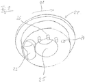
- an end wall 22 is provided, which has a first and a second inlet opening 23, 24 (cf. FIG. 2 ).
- the first inlet opening 23 is designed as an inlet opening for the base paste of a dental impression mass, while the second inlet opening 24 is formed for the catalyst paste of the impression mass. Since the mixing ratio in the illustrated mixer 1 is approximately 5: 1, the first inlet opening 23 is significantly larger than the second inlet opening 24.
- an opening 25 for the passage of the rotor 3 is provided.
- the rotor 3 is connected via a coupling 30 located at the first end 20 of the mixing tube 2 (cf. FIG. 3 ) with a drive element (not shown) coupled.
- the rotor 3 is guided through the opening 25 and also stored in this opening 25.
- the drive element may in particular be part of the output device and drive the rotor 3 in the predetermined direction of rotation 91.
- the rotor 3 has a rotor disk 32 arranged on the rotor hub 31 with driver elements 33 directed towards the end wall 22, wherein the outer ends of the individual carrier elements 33 are bent in the form of blades in the direction of rotation 91 of the rotor 3. Between the individual carrier elements 33, slit-shaped rotor disk openings 34 are provided in the radial direction. On the side facing away from the end wall 22 side of the rotor disk 32 are boom 35th provided on the rotor hub 31, which are aligned with the rotor disk openings 34 substantially.
- mixing elements 36 are provided on the rotor hub 31, the mixing elements 36 being arranged in five mixing element groups 37 in which all associated mixing elements 36 are arranged in a plane perpendicular to the axis 90 of the rotor 3.
- the mixing elements 36 extend - as well as the driving elements 33 and the boom 35 - each of the rotor hub 31 of the rotor 3 to the inner wall 27 of the mixing tube. 2
- pins 26 are provided which project in the direction of the rotor disk 32.
- the area farther in the direction of rotation of the rotor 3 between the second and the first inlet openings 24, 23 is pin-free.
- the pins 26 are all arranged at the same distance from the axis 90 of the rotor 3.
- the entrainment elements 33 on the rotor 3 have recesses 38, through which the pins 26 projecting from the end wall 22 can slide on rotation of the rotor 3. The pins 26 therefore do not hinder the rotation of the rotor 3 about its axis 90.
- the mixer 1 is used for mixing a dental impression material consisting of two components - a base paste and a catalyst paste.
- the two components should be in one Ratio of 5: 1 are mixed, wherein the base paste usually has a significantly higher viscosity than the catalyst paste.
- the dynamic mixer 1 is connected at the first end 20 of the mixing tube 2 with dispensing ports and an output device for the two components of a dental impression material.
- the connection is such that the dispenser pushes the first component - the base paste - through the first inlet port 23 and the second component - the catalyst paste - through the second inlet port 24 into the mixer 1.
- a drive unit of the output device is connected via the coupling 30 with the rotor 3 of the mixer 1 such that the drive unit can drive the rotor 3 in the predetermined direction of rotation 91.
- the dispenser inserts the base paste into the mixer 1 through the first larger inlet port 23. There it is entrained by the entrainment elements 33 of the driven by the drive unit of the output device rotor and conveyed to the pins 26 in the direction of the second smaller inlet opening 24 out. By the pins 26, which can slide through the recesses 38 in the driving elements 33, the base paste is sheared, whereby the viscosity is reduced.
- the catalyst paste is added, which mixes better with it due to the reduction of the viscosity of the base paste.
- the mixture of base paste and catalyst paste which is still rather heterogeneous at this point, then passes through the rotor disk openings 34 past the arms 35 to the mixing elements 36.
- base paste and catalyst paste are further mixed together that emerges at the end of the mixing tube 2, a homogeneous mixture from the outlet opening 21.
- the exiting mixture is homogenized in such a way that it can be used directly as a dental impression material.
- the mixer according to the invention with excellent homogenization neither the temperature nor the extrusion pressure of the components or the mixture is significantly increased compared to other known from the prior art dynamic mixers, so that the predetermined processing times and hardening times of the impression materials are guaranteed.
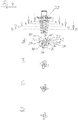
- FIG. 4 Further details of the rotor 3 are shown, wherein the figure next to a side view of the rotor 3 still four sectional views AD includes.
- the mixing elements 36 of the first four mixing element groups 37 seen from the rotor disk 32 are shown in each case.
- Each mixing element group 37 comprises four mixing elements 36, which are distributed uniformly over the circumference of the rotor hub 31.
- front edge 39 is parallel to the rear edge 40.
- the mixing elements 36 each extend to the inner wall 27 of the mixing tube 2, which in FIG. 4A is exemplified by a dashed line.
- mixing element group 37 is provided between two mixing elements 36, a deflecting element 41.
- the deflecting element 41 is arranged between the front edge 39 'of a first mixing element 36 and rear edge 40' of the adjacent mixing element 36. By the deflection element 41, the free area between these two mixing elements 36 is reduced.
- the deflection element 41 does not have to be arranged between two mixing elements 36.
- the deflecting element 41 can also be designed detached from the mixing elements 36.
- the fifth and last mixing element group 37 seen from the rotor disk 32 does not comprise a deflection element 41.
Description
Die Erfindung betrifft einen dynamischen Mischer für viskose Massen, insbesondere für Komponenten von zahnärztlichen Abdruckmassen sowie dessen Verwendung für zahnärztliche Abdruckmassen.The invention relates to a dynamic mixer for viscous masses, in particular for components of dental impression materials and its use for dental impression materials.
Aus der
Dabei ist auch bekannt, eine der Einlassöffnungen, durch die bei typischerweise ungleichen Verhältnissen der einzelnen zu mischenden Komponenten eine größere Menge der einen Komponente hindurchtreten soll, mit einem größeren Querschnitt als diejenigen Einlassöffnungen, durch die eine kleinere Menge der anderen Komponenten hindurchtreten soll, zu versehen. Entsprechendes ist u. a. in
Die Komponenten zahnärztlicher Abdruckmassen weisen unterschiedliches Fließverhalten auf. Um die vorgesehene Abdruckqualität sowie vorgegebene Verarbeitungs- und Erhärtungszeiten zu gewährleisten, muss für eine möglichst gleichbleibende, zügige und homogene Vermischung gesorgt werden. Dabei sind Temperaturerhöhung und Auspressdruck möglichst gering zu halten.The components of dental impression materials have different flow behavior. In order to ensure the intended impression quality as well as given processing and hardening times, care must be taken to ensure the most consistent, rapid and homogeneous mixing possible. In this case, temperature increase and discharge pressure should be kept as low as possible.
Der Erfindung liegt die Aufgabe zugrunde, einen gegenüber dem Stand der Technik verbesserten dynamischen Mischer zu schaffen.The invention has for its object to provide a comparison with the prior art improved dynamic mixer.
Diese Aufgabe wird gelöst durch einen dynamischen Mischer gemäß dem Hauptanspruch. Vorteilhafte Weiterbildungen sind Gegenstand der abhängigen Ansprüche.This object is achieved by a dynamic mixer according to the main claim. Advantageous developments are the subject of the dependent claims.
Demnach betrifft die Erfindung einen dynamischen Mischer für die Komponenten viskoser Massen, insbesondere für die Komponenten von zahnärztlichen Abdruckmassen, mit einem Mischrohr und einem darin angeordneten, antreibbaren Rotor, wobei das Mischrohr an seinem ersten Ende eine Stirnwand mit wenigstens zwei Einlassöffnungen für die Komponenten und an seinem anderen Ende eine Auslassöffnung für das Gemisch aufweist, wobei der Rotor eine Rotorscheibe mit wenigstens einem zur Stirnwand gerichteten Mitnahmeelement und wenigstens einer Rotorscheibenöffnung zum Durchtritt der Komponenten zur von der Stirnwand abgewandten Seite der Rotorscheibe aufweist, wobei an der Rotornabe zwischen Rotorscheibe und Auslassöffnung des Mischrohrs wenigstens ein Mischelement angeordnet ist und wobei an der Stirnwand zur Rotorscheibe hin wenigstens ein vorstehender Stift angeordnet ist und das wenigstens eine Mitnahmeelement wenigstens eine Ausnehmung für den wenigstens einen Stift aufweist.Accordingly, the invention relates to a dynamic mixer for the components of viscous masses, in particular for the components of dental impression materials, with a mixing tube and disposed therein, a drivable rotor, wherein the mixing tube at its first end an end wall with at least two inlet openings for the components and at the rotor has a rotor disk with at least one entrainment element directed toward the end wall and at least one rotor disk opening for the passage of the components to the side facing away from the end wall of the rotor disk, wherein at the rotor hub between the rotor disk and outlet opening of the mixing tube at least one mixing element is arranged and wherein at least one protruding pin is arranged on the end wall toward the rotor disk and the at least one catch element has at least one recess for the at least one pin.
Das Mischrohr kann an seinem ersten Ende mit einem Behälter mit Ausgabeöffnungen und einem Ausgabegerät für die Komponenten verbunden werden. Aufgrund des wenigstens einen Mitnahmeelements folgen bei dem erfindungsgemäßen Mischer die durch die Einlassöffnungen eintretenden Komponenten zunächst der Rotation des Rotors. Durch diese Mitnahme wird die durch eine erste Einlassöffnung eingetretene erste Komponente an der Einlassöffnung für eine weitere Komponente vorbeigeführt. Die erste Komponente wird dabei mit der durch die weitere Einlassöffnung eintretenden Komponente vermischt, womit zu diesem Zeitpunkt ein noch sehr heterogenes Gemisch der einzelnen Komponenten vorliegt. Werden die Komponenten dem Mischer weiter zugeführt, füllt sich im Wesentlichen zunächst der Bereich zwischen Stirnwand und Rotorscheibe vollständig, bevor anschließend das beschriebene Gemisch durch die wenigstens eine Rotorscheibenöffnung in der Rotorscheibe gedrückt wird. Im Bereich zwischen Rotorscheibe und Auslassöffnung des Mischrohrs wird das Gemisch durch das wenigstens eine Mischelement weiter homogenisiert, bevor es an der Auslassöffnung austritt.The mixing tube may be connected at its first end to a container having discharge ports and an output device for the components. Due to the at least one entrainment element, the components entering through the inlet openings initially follow the rotation of the rotor in the mixer according to the invention. As a result of this entrainment, the first component which has entered through a first inlet opening is led past the inlet opening for a further component. In this case, the first component is mixed with the component entering through the further inlet opening, by which means there is still a very heterogeneous mixture of the individual components at this time. If the components are fed further to the mixer, the area between the end wall and the rotor disk fills up substantially first, before the mixture described is subsequently pressed through the at least one rotor disk opening in the rotor disk. In the area between the rotor disk and the outlet opening of the mixing tube, the mixture is further homogenized by the at least one mixing element before it emerges at the outlet opening.
Der Erfindung liegt die Erkenntnis zugrunde, dass die homogene Vermischung der einzelnen Komponenten auch über einen breiten Viskositätsbereich verbessert werden kann, wenn das regelmäßig vorliegende unterschiedliche Fließverhalten der einzelnen zu mischenden Komponenten zu Beginn des Mischvorgangs weitestgehend ausgeglichen wird. Dieser Ausgleich wird durch das Zusammenwirken des erfindungsgemäßen wenigstens einen, zur Rotorscheibe hin gerichteten Stifts an der Stirnwand und des wenigstens einen Mitnahmeelements im Bereich der wenigstens einen Ausnehmung erreicht. Indem das wenigstens eine Mitnahmeelement eine Aufnehmung aufweist, durch die der genannte wenigstens eine Stift bei Rotation des Rotors hindurchgleitet, wird die in Rotationsrichtung vor dem Mitnahmeelement befindliche Masse geschert. Dadurch kann deren Viskosität reduziert und somit die Durchmischbarkeit mit weiteren Komponenten verbessert werden. Das so entstandene Gemisch gelangt dann über die wenigstens eine Rotorscheibenöffnung zu dem wenigstens einen Mischelement und wird dort weiter gemischt. Das homogenisierte Gemisch tritt anschließend aus der Auslassöffnung des Mischers aus.The invention is based on the finding that the homogeneous mixing of the individual components can also be improved over a wide viscosity range if the regularly present different flow behavior of the individual components to be mixed at the beginning of the mixing process is largely compensated. This compensation is achieved by the interaction of the inventive at least one, directed towards the rotor disc pin on the end wall and the at least one driving element in the region of at least one recess. By the at least one entrainment element has a Aufnehmung, through which said at least one pin slides during rotation of the rotor, the mass located in the direction of rotation in front of the driving element is sheared. As a result, their viscosity can be reduced and thus the mixability with other components can be improved. The resulting mixture then passes through the at least one rotor disk opening to the at least one mixing element and is further mixed there. The homogenized mixture then exits the outlet port of the mixer.
Durch die erfindungsgemäße Anordnung von wenigstens einem Stift an der Stirnwand kann die Homogenität des aus der Auslassöffnung des Mischers heraustretenden Gemisches gegenüber einem Mischer ohne entsprechende Stifte deutlich verbessert werden. Gleichzeitig wird die Temperatur der Komponenten bzw. des Gemischs nicht wesentlich erhöht.The inventive arrangement of at least one pin on the end wall, the homogeneity of the emerging from the outlet of the mixer mixture over a mixer without corresponding pins can be significantly improved. At the same time, the temperature of the components or the mixture is not significantly increased.
Die Verbesserung der Durchmischbarkeit kann an einem Beispiel verdeutlicht werden: Bei einer zahnärztlichen Abdruckmasse müssen bspw. eine Basispaste und eine Katalysatorpaste in einem vorgegebenen Verhältnis - z. B. 5:1 - miteinander vermischt werden. Dabei strömen die genannten Pasten durch verschieden große (5:1) Einlassöffnungen in einen dynamischen Mischer. Bei Verwendung eines erfindungsgemäßen Mischers kann dabei eine bei Rotation des Rotors durch ein Mitnahmeelement mitgeführte Menge an Basispaste durch den wenigstens einen erfindungsgemäß vorgesehenen Stift geschert werden, bevor diese Menge an Basispaste an der Einlassöffnung für die Katalysatorpaste vorbeigeführt wird. Dadurch wird die Viskosität der Basispaste reduziert und dadurch die Durchmischbarkeit mit der Katalysatorpaste verbessert.The improvement of the intermixability can be illustrated by an example: In a dental impression material, for example, a base paste and a catalyst paste in a predetermined ratio -. B. 5: 1 - are mixed together. The pastes flow through differently sized (5: 1) inlet openings into a dynamic mixer. When using a mixer according to the invention, a quantity of base paste entrained by a driving element during rotation of the rotor can be sheared by the at least one pin provided according to the invention before this amount of base paste is passed past the inlet opening for the catalyst paste. This reduces the viscosity of the base paste and thereby improves the mixability with the catalyst paste.
Es ist bevorzugt, wenn der wenigstens eine Stift eine Länge aufweist, die wenigstens 2/3 des Abstands der Stirnwand zur Rotorscheibe beträgt. Weiter bevorzugt erstreckt sich der wenigstens eine Stift bis zur Rotorscheibe. Besonders bevorzugt sind die Höhe des wenigstens einen Mitnahmeelements der Rotorscheibe und die Länge des wenigstens einen Stifts im Wesentlichen gleich.It is preferred if the at least one pin has a length that is at least 2/3 of the distance between the end wall and the rotor disk. More preferably, the at least one pin extends to the rotor disk. Particularly preferably, the height of the at least one entrainment element of the rotor disk and the length of the at least one pin are substantially equal.
Bevorzugt beträgt der Abstand zwischen Stirnwand und Rotorscheibe im Wesentlichen mindestens 5 %, vorzugweise mindestens 10 %, weiter vorzugsweise 10 bis 30 % der Gesamtlänge des Mischrohrs.Preferably, the distance between the end wall and rotor disk is substantially at least 5%, preferably at least 10%, more preferably 10 to 30% of the total length of the mixing tube.
Es ist bevorzugt, wenn mehr als ein Stift an der Stirnwand vorgesehen ist. Durch eine Mehrzahl von Stiften kann die Viskosität einer Masse in größerem Maße reduziert werden und/oder können Viskositätsunterschiede der Komponenten besser ausgeglichen werden als durch einen einzelnen Stift. Die Stifte oder zumindest Gruppen von Stiften können dabei in jeweils gleichem Abstand zur Achse des Rotors angeordnet sein. Dies bietet den Vorteil, dass alle Stifte oder zumindest die Stifte einer Gruppe durch dieselbe Ausnehmung geführt werden können.It is preferred if more than one pin is provided on the end wall. By a plurality of pins, the viscosity of a mass can be reduced to a greater extent and / or viscosity differences of the components can be compensated better than by a single pin. The pins or at least groups of pins can be arranged in each case at the same distance from the axis of the rotor. This offers the advantage that all pins or at least the pins of a group can be guided through the same recess.
Es ist bevorzugt, wenn der wenigstens eine Stift in Drehrichtung des Rotors zwischen einer ersten größeren und einer zweiten kleineren Einlassöffnung angeordnet ist. Durch eine entsprechende Anordnung wird die Viskosität der durch die erste Einlassöffnung eintretenden Komponente reduziert, bevor dieser Komponente die zweite oder weitere Komponenten hinzugefügt werden. Wird der Mischer für zahnärztliche Abdruckmassen verwendet, ist die erste größere Einlassöffnung vorzugsweise für die Basispaste, die zweite kleinere Einlassöffnung bevorzugt für die Katalysatorpaste vorgesehen.It is preferred if the at least one pin is arranged in the direction of rotation of the rotor between a first larger and a second smaller inlet opening. By appropriate arrangement, the viscosity of the component entering through the first inlet opening is reduced before the second or further components are added to this component. If the mixer is used for dental impression materials, the first larger inlet port is preferably for the base paste, the second smaller inlet opening is preferably provided for the catalyst paste.
Das von der Achse des Rotors entfernte Ende des wenigstens einen Mitnahmeelements ist vorzugsweise in Drehrichtung gebogen. Das genannte Ende des wenigstens einen Mitnahmeelements ist also schaufelförmig ausgebildet, sodass die in der Drehrichtung des Rotors vor einem Mitnahmeelement befindliche Masse im Bereich des schaufelförmig ausgestalteten Endes in Richtung der Achse des Rotors gedrängt wird.The remote from the axis of the rotor end of the at least one driving element is preferably bent in the direction of rotation. The said end of the at least one driving element is thus formed scoop-shaped, so that in the direction of rotation of the rotor located in front of a driving element mass is urged in the direction of the axis of the rotor in the region of the blade-shaped end.
Die wenigstens eine Rotorscheibenöffnung zum Durchtritt der vorgemischten Komponenten zur von der Stirnwand abgewandten Seite der Rotorscheibe ist bevorzugt ein radial angeordneter Schlitz. Auf der von der Stirnwand abgewandten Seite der Rotorscheibe ist an der Rotornabe weiter vorzugsweise wenigstens ein mit einem Schlitz im Wesentlichen fluchtender Ausleger angeordnet. Das Komponentengemisch, welches durch die Rotorscheibenöffnung hindurchtritt, wird durch den Ausleger umgelenkt und geschert. Es ist bevorzugt, wenn die Anzahl der Ausleger der Anzahl der Rotorscheibenöffnung entspricht.The at least one rotor disk opening for the passage of the premixed components to the side of the rotor disk facing away from the end wall is preferably a radially arranged slot. On the side facing away from the end wall of the rotor disk at the rotor hub more preferably at least one aligned with a slot substantially cantilever is arranged. The component mixture that passes through the rotor disc opening is deflected and sheared by the cantilever. It is preferred if the number of cantilevers corresponds to the number of rotor disc openings.
Es ist bevorzugt, wenn das wenigstens eine Mischelement als von der Rotornabe abstehender Mischflügel ausgestaltet ist, der sich bis zur Innenwand des Mischrohrs erstreckt. Dabei verläuft die in Drehrichtung des Rotors vordere Kante des Mischflügels vorzugsweise parallel zu der hinteren Kante. Vorzugsweise ist mehr als ein Mischelement vorgesehen. Die Mischelemente sind dann bevorzugt in mehreren in axialer Richtung der Achse des Rotors beabstandeten Mischelementgruppen angeordnet, wobei die Mischelemente einer Mischelementgruppe in einer Ebene senkrecht zur Achse des Rotors angeordnet sind.It is preferred if the at least one mixing element is designed as a mixing blade protruding from the rotor hub, which extends up to the inner wall of the mixing tube. In this case, the front edge of the mixing blade in the direction of rotation of the rotor preferably runs parallel to the rear edge. Preferably, more than one mixing element is provided. The mixing elements are then preferably in a plurality of mixing element groups spaced apart in the axial direction of the axis of the rotor arranged, wherein the mixing elements of a mixing element group are arranged in a plane perpendicular to the axis of the rotor.
In einer Mischelementengruppe kann ein Umlenkelement vorgesehen sein. Das Umlenkelement kann dabei zwischen der vorderen Kante eines ersten Mischelements und der hinteren Kante des benachbarten Mischelements angeordnet sein und die freie Fläche zwischen den beiden Mischelementen verkleinern. Das parallel zur Achse des Rotors auf das Umlenkelement auftreffende Gemisch strömt dadurch verstärkt in Richtung des benachbarten Mischelements. Alternativ kann ein Umlenkelement auch losgelöst von den Mischelementen ausgestaltet sein, d. h. eine Formgebung aufweisen, die unabhängig von Mischelementen ist. Vorzugsweise umfasst die der Auslassöffnung des Mischrohrs nächstgelegene Mischelementgruppe kein Umlenkelement.In a mixing element group, a deflecting element may be provided. The deflecting element can be arranged between the front edge of a first mixing element and the rear edge of the adjacent mixing element and reduce the free area between the two mixing elements. The mixture impinging on the deflecting element parallel to the axis of the rotor thereby flows increasingly in the direction of the adjacent mixing element. Alternatively, a deflecting element can also be designed detached from the mixing elements, i. H. have a shape that is independent of mixing elements. Preferably, the mixing element group closest to the outlet opening of the mixing tube does not comprise a deflecting element.
Der erfindungsgemäße Mischer wird bevorzugt für zahnärztliche Abdruckmassen aller Typen (0-3) verwendet. Zur Erläuterung dieser Verwendung wird auf die vorstehenden Ausführungen verwiesen. Die zahnärztliche Abdruckmasse weist dabei vorzugweise eine Basispaste und eine Katalysatorpaste auf.The mixer according to the invention is preferably used for dental impression materials of all types (0-3). To explain this use, reference is made to the above statements. The dental impression material preferably has a base paste and a catalyst paste.
Der erfindungsgemäße Mischer bewirkt insbesondere sowohl eine gute Durchmischung hochviskoser Pasten (bspw. elastomere Abformmassen des Typs 0, ISO 4823) bei relativ geringen Staudrücken als auch niedrigviskoser Pasten (bspw. elastomere Abformmassen des Typs 3, ISO 4823). Weiterhin werden auch stark strukturviskose und thixotrope Komponenten verbessert vermischt. Der Mischer ist dadurch universell, d.h. für eine große Bandbreite sehr unterschiedlicher Materialien einsetzbar. Ein Anwender kann dadurch einen Mischer für alle in der täglichen Praxis benötigten Materialien verwenden, wodurch die potenzielle Fehlerquelle der Auswahl des richtigen Mischers beseitigt wird.The mixer according to the invention in particular effects both a thorough mixing of highly viscous pastes (for example elastomeric impression compounds of the type 0, ISO 4823) at relatively low dynamic pressures and low-viscosity pastes (for example elastomeric impression compounds of the
Die Erfindung wird nun anhand einer vorteilhaften Ausführungsform unter Bezugnahme auf die beigefügten Zeichnungen beispielhaft beschrieben. Es zeigen:
-
Figur 1 : eine erste Ausführungsform eines erfindungsgemäßen dynamischen Mischers; -
Figur 2 : eine Detaildarstellung der Stirnwand des dynamischen Mischers ausFigur 1 ; -
Figur 3 : eine Draufsicht des Rotors des dynamischen Mischers ausFigur 1 ; und -
Figur 4 : eine Seitenansicht sowie vier Schnittansichten des Rotors des dynamischen Mischers ausFigur 1 .
-
FIG. 1 a first embodiment of a dynamic mixer according to the invention; -
FIG. 2 : a detailed view of the front wall of the dynamic mixerFIG. 1 ; -
FIG. 3 : a top view of the rotor of the dynamic mixerFIG. 1 ; and -
FIG. 4 : A side view and four sectional views of the rotor of the dynamic mixerFIG. 1 ,
In
Der Mischer 1 umfasst ein Mischrohr 2 und einen darin angeordneten Rotor 3, der um die Achse 90 drehbar gelagert ist. Der Rotor 3 weist eine bevorzugte vorgegebene Drehrichtung auf, die durch den Pfeil 91 angedeutet ist.The mixer 1 comprises a mixing
Das Mischrohr 2 ist an seinem ersten Ende 20 zur Verbindung mit einer Ausgabeanordnung (bspw. MixStar, DMG; Pentamix, 3M) umfassend einen Behälter mit Ausgabeöffnungen und ein Ausgabegerät (nicht dargestellt) für die zwei Komponenten einer zahnärztlichen Abdruckmasse ausgebildet und weist an seinem anderen Ende eine Auslassöffnung 21 auf. An dem ersten Ende 20 ist eine Stirnwand 22 vorgesehen, die eine erste und eine zweite Einlassöffnung 23, 24 aufweist (vgl.
Der Rotor 3 ist über eine an dem ersten Ende 20 des Mischrohrs 2 befindliche Kopplung 30 (vgl.
Der Rotor 3 weist eine an der Rotornabe 31 angeordnete Rotorscheibe 32 mit zur Stirnwand 22 gerichteten Mitnahmeelementen 33 auf, wobei die äußeren Enden der einzelnen Mitnahmeelemente 33 schaufelförmig in Drehrichtung 91 des Rotors 3 umgebogen sind. Zwischen den einzelnen Mitnahmeelementen 33 sind in radialer Richtung spaltförmige Rotorscheibenöffnungen 34 vorgesehen. Auf der von der Stirnwand 22 abgewandten Seite der Rotorscheibe 32 sind Ausleger 35 an der Rotornabe 31 vorgesehen, die mit den Rotorscheibenöffnungen 34 im Wesentlichen fluchten.The
Weiter zur Auslassöffnung 21 des Mischrohrs 2 hin sind Mischelemente 36 an der Rotornabe 31 vorgesehen, wobei die Mischelemente 36 in fünf Mischelementgruppen 37 angeordnet sind, bei denen alle zugehörigen Mischelemente 36 in einer Ebene senkrecht zur Achse 90 des Rotors 3 angeordnet sind. Die Mischelemente 36 erstrecken sich - wie auch die Mitnahmeelemente 33 und die Ausleger 35 - jeweils von der Rotornabe 31 des Rotors 3 bis zu Innenwand 27 des Mischrohrs 2.Further toward the outlet opening 21 of the mixing
An der Stirnwand 22 sind in Drehrichtung 91 des Rotors 3 gesehen zwischen der ersten und der zweiten Einlassöffnung 23, 24 drei Stifte 26 vorgesehen, die in Richtung der Rotorscheibe 32 ragen. Der Bereich weiter in Drehrichtung des Rotors 3 zwischen der zweiten und der ersten Einlassöffnung 24, 23 ist stiftfrei. Die Stifte 26 sind dabei alle im gleichen Abstand zur Achse 90 des Rotors 3 angeordnet. Die Mitnahmeelemente 33 am Rotor 3 weisen Aufnehmungen 38 auf, durch die die aus der Stirnwand 22 hervorstehenden Stifte 26 bei Rotation des Rotors 3 hindurchgleiten können. Die Stifte 26 behindern die Rotation des Rotors 3 um seine Achse 90 demnach also nicht.On the
Die Funktionsweise des dargestellten dynamischen Mischers 1 wird nun anhand einer beispielhaften Verwendung dargestellt. In diesem Beispiel wird der Mischer 1 zur Anmischung einer zahnärztlichen Abdruckmasse verwendet, die aus zwei Komponenten - einer Basispaste und eine Katalysatorpaste - besteht. Die beiden Komponenten sollen dabei in einem Verhältnis von 5:1 gemischt werden, wobei die Basispaste üblicherweise eine deutlich höhere Viskosität als die Katalysatorpaste aufweist.The operation of the illustrated dynamic mixer 1 will now be illustrated by way of example use. In this example, the mixer 1 is used for mixing a dental impression material consisting of two components - a base paste and a catalyst paste. The two components should be in one Ratio of 5: 1 are mixed, wherein the base paste usually has a significantly higher viscosity than the catalyst paste.
Der dynamische Mischer 1 wird an dem ersten Ende 20 des Mischrohrs 2 mit Ausgabeöffnungen und einem Ausgabegerät für die beiden Komponenten einer zahnärztlichen Abdruckmasse verbunden. Die Verbindung ist dergestalt, dass das Ausgabegerät die erste Komponente - die Basispaste - durch die erste Einlassöffnung 23 und die zweite Komponente - die Katalysatorpaste - durch die zweite Einlassöffnung 24 in den Mischer 1 drückt. Gleichzeitig wird eine Antriebseinheit des Ausgabegerätes über die Kopplung 30 derart mit dem Rotor 3 des Mischers 1 verbunden, dass die Antriebseinheit den Rotor 3 in die vorgegebene Drehrichtung 91 antreiben kann.The dynamic mixer 1 is connected at the first end 20 of the mixing
Das Ausgabegerät bringt die Basispaste durch die erste größere Einlassöffnung 23 in den Mischer 1 ein. Dort wird sie durch die Mitnahmeelemente 33 des durch die Antriebseinheit des Ausgabegerätes angetriebenen Rotors mitgenommen und an den Stiften 26 vorbei in Richtung zur zweiten kleineren Einlassöffnung 24 hin gefördert. Durch die Stifte 26, die durch die Ausnehmungen 38 in den Mitnahmeelementen 33 hindurchgleiten können, wird die Basispaste geschert, wodurch sich deren Viskosität reduziert.The dispenser inserts the base paste into the mixer 1 through the first
Über die zweite Einlassöffnung 24 wird die Katalysatorpaste hinzugefügt, die sich aufgrund der Reduzierung der Viskosität der Basispaste besser mit dieser vermengt. Das zu diesem Zeitpunkt noch eher heterogene Gemisch aus Basispaste und Katalysatorpaste gelangt dann durch die Rotorscheibenöffnungen 34 vorbei an den Auslegern 35 zu den Mischelementen 36. Durch die in Mischelementgruppen 37 angeordneten Mischelemente 36 werden Basispaste und Katalysatorpaste weiter miteinander vermischt, dass am Ende des Mischrohrs 2 ein homogenes Gemisch aus der Auslassöffnung 21 austritt. Das austretende Gemisch ist dabei derart homogenisiert, dass es als zahnärztliche Abdruckmasse direkt verwendbar ist.Via the second inlet opening 24, the catalyst paste is added, which mixes better with it due to the reduction of the viscosity of the base paste. The mixture of base paste and catalyst paste, which is still rather heterogeneous at this point, then passes through the
Durch den erfindungsgemäßen Mischer wird bei hervorragender Homogenisierung weder die Temperatur noch der Auspressdruck der Komponenten bzw. des Gemischs auch im Vergleich zu anderen aus dem Stand der Technik bekannten dynamischen Mischern merklich erhöht, sodass die vorgegebenen Verarbeitungszeiten und Erhärtungszeiten der Abdruckmassen gewährleistet sind.The mixer according to the invention, with excellent homogenization neither the temperature nor the extrusion pressure of the components or the mixture is significantly increased compared to other known from the prior art dynamic mixers, so that the predetermined processing times and hardening times of the impression materials are guaranteed.
In
Jede Mischelementgruppe 37 umfasst vier Mischelemente 36, die gleichmäßig über den Umfang der Rotornabe 31 verteilt angeordnet sind. Bei den Mischelementen 36 ist die in Drehrichtung 91 gesehene vordere Kante 39 parallel zur hinteren Kante 40. Weiterhin erstrecken sich die Mischelemente 36 jeweils bis zur Innenwand 27 des Mischrohrs 2, die in
Bei den in den Schnittdarstellungen der
Selbstverständlich muss das Umlenkelement 41 nicht zwischen zwei Mischelementen 36 angeordnet werden. Das Umlenkelement 41 kann auch von den Mischelementen 36 losgelöst ausgestaltet sein.Of course, the
Die von der von der Rotorscheibe 32 aus gesehene fünfte und letzte Mischelementgruppe 37 umfasst kein Umlenkelement 41.The fifth and last
Claims (12)
- Dynamic mixer (1) for the components of viscous compounds, in particular for the components of dental impression compounds, having a mixing tube (2) and, arranged therein, a drivable rotor (3), wherein the mixing tube (2) has at its first end (20) an end wall (22) having at least two inlet openings (23, 24) for the components, and at its other end an outlet opening (21) for the mixture, wherein the rotor (3) has a rotor disk (32) having at least one entraining element (33) that faces the end wall (22), and at least one rotor disk opening (34) for the components to pass through to the side of the rotor disk (32) remote from the end wall (22), wherein at least one mixing element (36) is arranged on the rotor hub (31) between the rotor disk (32) and the outlet opening (21) of the mixing tube (2),
characterized in that
at least one projecting pin (26) is arranged on the end wall (22) toward the rotor disk (32), and the at least one entraining element (33) has at least one recess (38) for the at least one pin (26). - Mixer according to Claim 1, characterized in that the at least one pin (26) has a length that is at least 2/3 of the spacing from the end wall (22) to the rotor disk (32), or the at least one pin (26) extends as far as the rotor disk (32).
- Mixer according to one of the preceding claims, characterized in that the height of the at least one entraining element (33) of the rotor disk (32) and the length of the at least one pin (26) are substantially the same.
- Mixer according to one of the preceding claims, characterized in that the spacing between the end wall (22) and the rotor disk (32) is at least 5%, preferably at least 10%, further preferably 10 to 30% of the total length of the mixing tube (2).
- Mixer according to one of the preceding claims, characterized in that more than one pin (26) is provided on the end wall (22), wherein the pins (26) or at least groups of pins (26) are arranged in each case at the same spacing from the axis (90) of the rotor (3).
- Mixer according to one of the preceding claims, characterized in that the at least one pin (26) is arranged, as seen in the direction of rotation (91) of the rotor (3), between a first, larger inlet opening (23) and a second, smaller inlet opening (24).
- Mixer according to one of the preceding claims, characterized in that the end of the at least one entraining element (33) that is remote from the axis (90) of the rotor (3) is curved around in the direction of rotation (91).
- Mixer according to one of the preceding claims, characterized in that the at least one rotor disk opening (34) is a radial slot, wherein preferably, on the side of the rotor disk (32) remote from the end wall (22), at least one arm (35) that is flush with the at least one slot is arranged on the rotor hub (31).
- Mixer according to one of the preceding claims, characterized in that more than one mixing element (36) is provided and the mixing elements (36) are preferably arranged in a plurality of mixing element groups (37) that are spaced in the axial direction of the axis (90) of the rotor (3), wherein the mixing elements (36) of a mixing element group (37) are arranged in a plane perpendicular to the axis (90) of the rotor (3).
- Mixer according to Claim 9, characterized in that a deflecting element (41) is provided in a mixing element group (37), wherein the deflecting element (41) is preferably a connecting surface between two adjacent mixing elements (36) and the free surface between these two mixing elements (36) is made smaller.
- Use of a dynamic mixer according to one of Claims 1 to 10 for dental impression compounds.
- Use according to Claim 11, characterized in that the dental impression compound has as the first component a base paste and as the second component a catalyst paste.
Applications Claiming Priority (2)
| Application Number | Priority Date | Filing Date | Title |
|---|---|---|---|
| DE201320009790 DE202013009790U1 (en) | 2013-12-04 | 2013-12-04 | Dynamic mixer |
| PCT/EP2014/076582 WO2015082620A1 (en) | 2013-12-04 | 2014-12-04 | Dynamic mixer and use thereof |
Publications (2)
| Publication Number | Publication Date |
|---|---|
| EP3077094A1 EP3077094A1 (en) | 2016-10-12 |
| EP3077094B1 true EP3077094B1 (en) | 2017-11-22 |
Family
ID=52023484
Family Applications (1)
| Application Number | Title | Priority Date | Filing Date |
|---|---|---|---|
| EP14811811.0A Active EP3077094B1 (en) | 2013-12-04 | 2014-12-04 | Dynamic mixer and use thereof |
Country Status (6)
| Country | Link |
|---|---|
| US (1) | US9943813B2 (en) |
| EP (1) | EP3077094B1 (en) |
| KR (1) | KR101713870B1 (en) |
| CN (1) | CN106061595B (en) |
| DE (1) | DE202013009790U1 (en) |
| WO (1) | WO2015082620A1 (en) |
Families Citing this family (1)
| Publication number | Priority date | Publication date | Assignee | Title |
|---|---|---|---|---|
| DE202013009790U1 (en) * | 2013-12-04 | 2015-03-05 | Mühlbauer Technology Gmbh | Dynamic mixer |
Family Cites Families (21)
| Publication number | Priority date | Publication date | Assignee | Title |
|---|---|---|---|---|
| DE3611048C2 (en) | 1986-04-02 | 1997-10-23 | Gyproc Gmbh Baustoffproduktion | mixer |
| DE3717057A1 (en) | 1987-05-21 | 1988-12-01 | Bayer Ag | METHOD FOR PRODUCING ISOCYANATES |
| DE8717424U1 (en) * | 1987-08-27 | 1988-11-17 | Gurit-Essex Ag, Freienbach, Ch | |
| DE9017323U1 (en) | 1990-12-21 | 1992-04-16 | Thera Patent Gmbh & Co Kg Gesellschaft Fuer Industrielle Schutzrechte, 8031 Seefeld, De | |
| EP1138396B1 (en) * | 1998-10-14 | 2005-12-28 | Kettenbach GmbH & CO. KG | Opener for opening a tubular bag comprising a pasty material |
| DE19947331C2 (en) * | 1999-10-01 | 2002-02-28 | 3M Espe Ag | Dynamic mixer |
| US6443612B1 (en) * | 1999-12-02 | 2002-09-03 | Wilhelm A. Keller | Dynamic mixer |
| EP1110599B1 (en) | 1999-12-23 | 2003-04-09 | Ernst Mühlbauer GmbH & Co.KG | Dynamic mixer for dental impression pastes |
| DE10164385C1 (en) * | 2001-12-28 | 2003-03-06 | Kettenbach Gmbh & Co Kg | Device for mixing two paste-like substances for dental work includes first channel extending through coupling section and having first and second parts with adjoining deflection section inbetween to ensure constant mixing ratio at outlet |
| DE20302987U1 (en) * | 2003-02-24 | 2003-04-24 | Muehlbauer Ernst Gmbh & Co Kg | Dynamic mixer, used for mixing components of dentistry compositions, comprises mixing tube, rotor delimiting annular mixing channel, and wall with inlet openings for components |
| WO2005082549A2 (en) * | 2004-02-27 | 2005-09-09 | Heraeus Kulzer Gmbh | Method for the production of dental moulding materials and device therefor |
| DE102004020410B4 (en) | 2004-04-23 | 2007-08-02 | Heraeus Kulzer Gmbh | Dynamic mixer for pseudoplastic pastes |
| JP5389032B2 (en) * | 2007-09-10 | 2014-01-15 | スルザー ミックスパック アクチェンゲゼルシャフト | Dynamic mixer |
| US7731413B2 (en) * | 2008-02-20 | 2010-06-08 | Zhermack S.P.A. | Mixer for multi-components substance for dental casting |
| KR20100004377U (en) * | 2008-10-20 | 2010-04-29 | 신봉희 | Tip of automixer for dental |
| BR112013015378B1 (en) * | 2011-02-28 | 2020-12-08 | Sulzer Mixpac Ag | dynamic mixer for a variety of fluid components |
| AU2012222534B2 (en) * | 2011-02-28 | 2017-06-08 | Sulzer Mixpac Ag | Dynamic mixer |
| US8365462B2 (en) | 2011-05-31 | 2013-02-05 | Heliae Development, Llc | V-Trough photobioreactor systems |
| KR101091062B1 (en) | 2011-07-04 | 2011-12-08 | (주) 세일덴텍 | A mixing tip of automatic style dental impression material |
| DE202013009790U1 (en) * | 2013-12-04 | 2015-03-05 | Mühlbauer Technology Gmbh | Dynamic mixer |
| KR20150078712A (en) * | 2013-12-31 | 2015-07-08 | 김인자 | Structure for mixing tip of dental impression material |
-
2013
- 2013-12-04 DE DE201320009790 patent/DE202013009790U1/en not_active Expired - Lifetime
-
2014
- 2014-12-04 KR KR1020167014348A patent/KR101713870B1/en active IP Right Grant
- 2014-12-04 CN CN201480065721.9A patent/CN106061595B/en active Active
- 2014-12-04 EP EP14811811.0A patent/EP3077094B1/en active Active
- 2014-12-04 WO PCT/EP2014/076582 patent/WO2015082620A1/en active Application Filing
- 2014-12-04 US US15/038,170 patent/US9943813B2/en active Active
Also Published As
| Publication number | Publication date |
|---|---|
| CN106061595B (en) | 2018-10-02 |
| DE202013009790U1 (en) | 2015-03-05 |
| WO2015082620A1 (en) | 2015-06-11 |
| US9943813B2 (en) | 2018-04-17 |
| US20160288066A1 (en) | 2016-10-06 |
| KR20160098207A (en) | 2016-08-18 |
| EP3077094A1 (en) | 2016-10-12 |
| KR101713870B1 (en) | 2017-03-09 |
| CN106061595A (en) | 2016-10-26 |
Similar Documents
| Publication | Publication Date | Title |
|---|---|---|
| EP1110599B1 (en) | Dynamic mixer for dental impression pastes | |
| DE10112904B4 (en) | Dynamic mixer and method for mixing at least two paste components | |
| EP1099470B1 (en) | Device for mixing two pasty materials, especially for mixing a dental impression material with a catalyst material | |
| DE19947331C2 (en) | Dynamic mixer | |
| EP1029585B1 (en) | Apparatus for delivering a mixed multi-component substance, in particular for use in dentistry | |
| EP2680959B1 (en) | Dynamic mixer and use thereof | |
| WO2003055582A1 (en) | Device for mixing two pasty materials, in particular for mixing a dental impression material with a catalyst material | |
| CH699191A1 (en) | A dispensing with individual syringes and syringe holder. | |
| EP0378806A2 (en) | Device for mixing and dispensing pasty products | |
| WO2000021652A1 (en) | Device for mixing two pasty materials, especially for mixing a dental impression material with a catalyst material | |
| EP2848320A1 (en) | Connector for connecting a storage container to a static mixer | |
| EP2444336B1 (en) | Double discharge device | |
| EP1885620A1 (en) | Applicator for two or more components | |
| EP2548635B1 (en) | Dynamic mixer with a seal | |
| EP3077094B1 (en) | Dynamic mixer and use thereof | |
| EP2258468B1 (en) | Mixing system for dual component cartridges | |
| EP1900443B1 (en) | Device for mixing a binder and a hardener component for producing a ready-to-use body filler | |
| EP1595594B1 (en) | Dynamic mixer | |
| DE102004051063A1 (en) | Internal mixer for kneading plastic masses | |
| EP1720664A1 (en) | Method for the production of dental moulding materials and device therefor | |
| DE102013103552A1 (en) | syringe | |
| EP2258466A1 (en) | Mixing system for dual component cartridges | |
| DE202009007919U1 (en) | Mixing system for two-component cartridge | |
| EP3658265A1 (en) | Mixer | |
| DE102017117198A1 (en) | mixer |
Legal Events
| Date | Code | Title | Description |
|---|---|---|---|
| PUAI | Public reference made under article 153(3) epc to a published international application that has entered the european phase |
Free format text: ORIGINAL CODE: 0009012 |
|
| 17P | Request for examination filed |
Effective date: 20160701 |
|
| AK | Designated contracting states |
Kind code of ref document: A1 Designated state(s): AL AT BE BG CH CY CZ DE DK EE ES FI FR GB GR HR HU IE IS IT LI LT LU LV MC MK MT NL NO PL PT RO RS SE SI SK SM TR |
|
| AX | Request for extension of the european patent |
Extension state: BA ME |
|
| RIN1 | Information on inventor provided before grant (corrected) |
Inventor name: LAMOTT, KARSTEN |
|
| DAX | Request for extension of the european patent (deleted) | ||
| REG | Reference to a national code |
Ref country code: DE Ref legal event code: R079 Ref document number: 502014006358 Country of ref document: DE Free format text: PREVIOUS MAIN CLASS: B01F0013000000 Ipc: B01F0007000000 |
|
| GRAP | Despatch of communication of intention to grant a patent |
Free format text: ORIGINAL CODE: EPIDOSNIGR1 |
|
| RIC1 | Information provided on ipc code assigned before grant |
Ipc: A61C 9/00 20060101ALI20170703BHEP Ipc: B01F 7/00 20060101AFI20170703BHEP Ipc: B05C 17/005 20060101ALI20170703BHEP Ipc: B01F 13/00 20060101ALI20170703BHEP |
|
| INTG | Intention to grant announced |
Effective date: 20170720 |
|
| GRAS | Grant fee paid |
Free format text: ORIGINAL CODE: EPIDOSNIGR3 |
|
| GRAA | (expected) grant |
Free format text: ORIGINAL CODE: 0009210 |
|
| AK | Designated contracting states |
Kind code of ref document: B1 Designated state(s): AL AT BE BG CH CY CZ DE DK EE ES FI FR GB GR HR HU IE IS IT LI LT LU LV MC MK MT NL NO PL PT RO RS SE SI SK SM TR |
|
| REG | Reference to a national code |
Ref country code: GB Ref legal event code: FG4D Free format text: NOT ENGLISH |
|
| REG | Reference to a national code |
Ref country code: CH Ref legal event code: EP |
|
| REG | Reference to a national code |
Ref country code: IE Ref legal event code: FG4D Free format text: LANGUAGE OF EP DOCUMENT: GERMAN |
|
| REG | Reference to a national code |
Ref country code: AT Ref legal event code: REF Ref document number: 947898 Country of ref document: AT Kind code of ref document: T Effective date: 20171215 |
|
| REG | Reference to a national code |
Ref country code: DE Ref legal event code: R096 Ref document number: 502014006358 Country of ref document: DE Ref country code: FR Ref legal event code: PLFP Year of fee payment: 4 |
|
| REG | Reference to a national code |
Ref country code: CH Ref legal event code: NV Representative=s name: TROESCH SCHEIDEGGER WERNER AG, CH |
|
| REG | Reference to a national code |
Ref country code: NL Ref legal event code: MP Effective date: 20171122 |
|
| REG | Reference to a national code |
Ref country code: LT Ref legal event code: MG4D |
|
| PG25 | Lapsed in a contracting state [announced via postgrant information from national office to epo] |
Ref country code: NO Free format text: LAPSE BECAUSE OF FAILURE TO SUBMIT A TRANSLATION OF THE DESCRIPTION OR TO PAY THE FEE WITHIN THE PRESCRIBED TIME-LIMIT Effective date: 20180222 Ref country code: FI Free format text: LAPSE BECAUSE OF FAILURE TO SUBMIT A TRANSLATION OF THE DESCRIPTION OR TO PAY THE FEE WITHIN THE PRESCRIBED TIME-LIMIT Effective date: 20171122 Ref country code: ES Free format text: LAPSE BECAUSE OF FAILURE TO SUBMIT A TRANSLATION OF THE DESCRIPTION OR TO PAY THE FEE WITHIN THE PRESCRIBED TIME-LIMIT Effective date: 20171122 Ref country code: SE Free format text: LAPSE BECAUSE OF FAILURE TO SUBMIT A TRANSLATION OF THE DESCRIPTION OR TO PAY THE FEE WITHIN THE PRESCRIBED TIME-LIMIT Effective date: 20171122 Ref country code: LT Free format text: LAPSE BECAUSE OF FAILURE TO SUBMIT A TRANSLATION OF THE DESCRIPTION OR TO PAY THE FEE WITHIN THE PRESCRIBED TIME-LIMIT Effective date: 20171122 Ref country code: NL Free format text: LAPSE BECAUSE OF FAILURE TO SUBMIT A TRANSLATION OF THE DESCRIPTION OR TO PAY THE FEE WITHIN THE PRESCRIBED TIME-LIMIT Effective date: 20171122 |
|
| PG25 | Lapsed in a contracting state [announced via postgrant information from national office to epo] |
Ref country code: LV Free format text: LAPSE BECAUSE OF FAILURE TO SUBMIT A TRANSLATION OF THE DESCRIPTION OR TO PAY THE FEE WITHIN THE PRESCRIBED TIME-LIMIT Effective date: 20171122 Ref country code: HR Free format text: LAPSE BECAUSE OF FAILURE TO SUBMIT A TRANSLATION OF THE DESCRIPTION OR TO PAY THE FEE WITHIN THE PRESCRIBED TIME-LIMIT Effective date: 20171122 Ref country code: BG Free format text: LAPSE BECAUSE OF FAILURE TO SUBMIT A TRANSLATION OF THE DESCRIPTION OR TO PAY THE FEE WITHIN THE PRESCRIBED TIME-LIMIT Effective date: 20180222 Ref country code: GR Free format text: LAPSE BECAUSE OF FAILURE TO SUBMIT A TRANSLATION OF THE DESCRIPTION OR TO PAY THE FEE WITHIN THE PRESCRIBED TIME-LIMIT Effective date: 20180223 Ref country code: RS Free format text: LAPSE BECAUSE OF FAILURE TO SUBMIT A TRANSLATION OF THE DESCRIPTION OR TO PAY THE FEE WITHIN THE PRESCRIBED TIME-LIMIT Effective date: 20171122 |
|
| PG25 | Lapsed in a contracting state [announced via postgrant information from national office to epo] |
Ref country code: CZ Free format text: LAPSE BECAUSE OF FAILURE TO SUBMIT A TRANSLATION OF THE DESCRIPTION OR TO PAY THE FEE WITHIN THE PRESCRIBED TIME-LIMIT Effective date: 20171122 Ref country code: SK Free format text: LAPSE BECAUSE OF FAILURE TO SUBMIT A TRANSLATION OF THE DESCRIPTION OR TO PAY THE FEE WITHIN THE PRESCRIBED TIME-LIMIT Effective date: 20171122 Ref country code: EE Free format text: LAPSE BECAUSE OF FAILURE TO SUBMIT A TRANSLATION OF THE DESCRIPTION OR TO PAY THE FEE WITHIN THE PRESCRIBED TIME-LIMIT Effective date: 20171122 Ref country code: CY Free format text: LAPSE BECAUSE OF FAILURE TO SUBMIT A TRANSLATION OF THE DESCRIPTION OR TO PAY THE FEE WITHIN THE PRESCRIBED TIME-LIMIT Effective date: 20171122 Ref country code: DK Free format text: LAPSE BECAUSE OF FAILURE TO SUBMIT A TRANSLATION OF THE DESCRIPTION OR TO PAY THE FEE WITHIN THE PRESCRIBED TIME-LIMIT Effective date: 20171122 |
|
| REG | Reference to a national code |
Ref country code: DE Ref legal event code: R097 Ref document number: 502014006358 Country of ref document: DE |
|
| PG25 | Lapsed in a contracting state [announced via postgrant information from national office to epo] |
Ref country code: PL Free format text: LAPSE BECAUSE OF FAILURE TO SUBMIT A TRANSLATION OF THE DESCRIPTION OR TO PAY THE FEE WITHIN THE PRESCRIBED TIME-LIMIT Effective date: 20171122 Ref country code: SM Free format text: LAPSE BECAUSE OF FAILURE TO SUBMIT A TRANSLATION OF THE DESCRIPTION OR TO PAY THE FEE WITHIN THE PRESCRIBED TIME-LIMIT Effective date: 20171122 Ref country code: IT Free format text: LAPSE BECAUSE OF FAILURE TO SUBMIT A TRANSLATION OF THE DESCRIPTION OR TO PAY THE FEE WITHIN THE PRESCRIBED TIME-LIMIT Effective date: 20171122 |
|
| REG | Reference to a national code |
Ref country code: IE Ref legal event code: MM4A |
|
| PG25 | Lapsed in a contracting state [announced via postgrant information from national office to epo] |
Ref country code: MT Free format text: LAPSE BECAUSE OF FAILURE TO SUBMIT A TRANSLATION OF THE DESCRIPTION OR TO PAY THE FEE WITHIN THE PRESCRIBED TIME-LIMIT Effective date: 20171122 Ref country code: LU Free format text: LAPSE BECAUSE OF NON-PAYMENT OF DUE FEES Effective date: 20171204 |
|
| PLBE | No opposition filed within time limit |
Free format text: ORIGINAL CODE: 0009261 |
|
| STAA | Information on the status of an ep patent application or granted ep patent |
Free format text: STATUS: NO OPPOSITION FILED WITHIN TIME LIMIT |
|
| REG | Reference to a national code |
Ref country code: BE Ref legal event code: MM Effective date: 20171231 |
|
| 26N | No opposition filed |
Effective date: 20180823 |
|
| PG25 | Lapsed in a contracting state [announced via postgrant information from national office to epo] |
Ref country code: IE Free format text: LAPSE BECAUSE OF NON-PAYMENT OF DUE FEES Effective date: 20171204 |
|
| PG25 | Lapsed in a contracting state [announced via postgrant information from national office to epo] |
Ref country code: SI Free format text: LAPSE BECAUSE OF FAILURE TO SUBMIT A TRANSLATION OF THE DESCRIPTION OR TO PAY THE FEE WITHIN THE PRESCRIBED TIME-LIMIT Effective date: 20171122 Ref country code: BE Free format text: LAPSE BECAUSE OF NON-PAYMENT OF DUE FEES Effective date: 20171231 |
|
| PG25 | Lapsed in a contracting state [announced via postgrant information from national office to epo] |
Ref country code: MC Free format text: LAPSE BECAUSE OF FAILURE TO SUBMIT A TRANSLATION OF THE DESCRIPTION OR TO PAY THE FEE WITHIN THE PRESCRIBED TIME-LIMIT Effective date: 20171122 Ref country code: HU Free format text: LAPSE BECAUSE OF FAILURE TO SUBMIT A TRANSLATION OF THE DESCRIPTION OR TO PAY THE FEE WITHIN THE PRESCRIBED TIME-LIMIT; INVALID AB INITIO Effective date: 20141204 |
|
| PG25 | Lapsed in a contracting state [announced via postgrant information from national office to epo] |
Ref country code: RO Free format text: LAPSE BECAUSE OF FAILURE TO SUBMIT A TRANSLATION OF THE DESCRIPTION OR TO PAY THE FEE WITHIN THE PRESCRIBED TIME-LIMIT Effective date: 20171122 |
|
| PG25 | Lapsed in a contracting state [announced via postgrant information from national office to epo] |
Ref country code: MK Free format text: LAPSE BECAUSE OF FAILURE TO SUBMIT A TRANSLATION OF THE DESCRIPTION OR TO PAY THE FEE WITHIN THE PRESCRIBED TIME-LIMIT Effective date: 20171122 |
|
| PG25 | Lapsed in a contracting state [announced via postgrant information from national office to epo] |
Ref country code: TR Free format text: LAPSE BECAUSE OF FAILURE TO SUBMIT A TRANSLATION OF THE DESCRIPTION OR TO PAY THE FEE WITHIN THE PRESCRIBED TIME-LIMIT Effective date: 20171122 |
|
| PG25 | Lapsed in a contracting state [announced via postgrant information from national office to epo] |
Ref country code: PT Free format text: LAPSE BECAUSE OF FAILURE TO SUBMIT A TRANSLATION OF THE DESCRIPTION OR TO PAY THE FEE WITHIN THE PRESCRIBED TIME-LIMIT Effective date: 20171122 |
|
| PG25 | Lapsed in a contracting state [announced via postgrant information from national office to epo] |
Ref country code: AL Free format text: LAPSE BECAUSE OF FAILURE TO SUBMIT A TRANSLATION OF THE DESCRIPTION OR TO PAY THE FEE WITHIN THE PRESCRIBED TIME-LIMIT Effective date: 20171122 Ref country code: IS Free format text: LAPSE BECAUSE OF FAILURE TO SUBMIT A TRANSLATION OF THE DESCRIPTION OR TO PAY THE FEE WITHIN THE PRESCRIBED TIME-LIMIT Effective date: 20180322 |
|
| REG | Reference to a national code |
Ref country code: AT Ref legal event code: MM01 Ref document number: 947898 Country of ref document: AT Kind code of ref document: T Effective date: 20191204 |
|
| PG25 | Lapsed in a contracting state [announced via postgrant information from national office to epo] |
Ref country code: AT Free format text: LAPSE BECAUSE OF NON-PAYMENT OF DUE FEES Effective date: 20191204 |
|
| REG | Reference to a national code |
Ref country code: DE Ref legal event code: R079 Ref document number: 502014006358 Country of ref document: DE Free format text: PREVIOUS MAIN CLASS: B01F0007000000 Ipc: B01F0027000000 |
|
| PGFP | Annual fee paid to national office [announced via postgrant information from national office to epo] |
Ref country code: CH Payment date: 20230103 Year of fee payment: 9 |
|
| P01 | Opt-out of the competence of the unified patent court (upc) registered |
Effective date: 20230516 |
|
| PGFP | Annual fee paid to national office [announced via postgrant information from national office to epo] |
Ref country code: GB Payment date: 20231220 Year of fee payment: 10 |
|
| PGFP | Annual fee paid to national office [announced via postgrant information from national office to epo] |
Ref country code: FR Payment date: 20231219 Year of fee payment: 10 Ref country code: DE Payment date: 20231220 Year of fee payment: 10 |