EP2258466A1 - Mixing system for dual component cartridges - Google Patents
Mixing system for dual component cartridges Download PDFInfo
- Publication number
- EP2258466A1 EP2258466A1 EP09007452A EP09007452A EP2258466A1 EP 2258466 A1 EP2258466 A1 EP 2258466A1 EP 09007452 A EP09007452 A EP 09007452A EP 09007452 A EP09007452 A EP 09007452A EP 2258466 A1 EP2258466 A1 EP 2258466A1
- Authority
- EP
- European Patent Office
- Prior art keywords
- mouthpiece
- outlet channel
- mixing
- central
- component
- Prior art date
- Legal status (The legal status is an assumption and is not a legal conclusion. Google has not performed a legal analysis and makes no representation as to the accuracy of the status listed.)
- Withdrawn
Links
- 230000009977 dual effect Effects 0.000 title 1
- 239000000463 material Substances 0.000 claims description 71
- 238000001125 extrusion Methods 0.000 description 3
- 239000008240 homogeneous mixture Substances 0.000 description 2
- 238000000034 method Methods 0.000 description 2
- 239000000203 mixture Substances 0.000 description 2
- 238000007789 sealing Methods 0.000 description 2
- 239000000853 adhesive Substances 0.000 description 1
- 230000001070 adhesive effect Effects 0.000 description 1
- 230000004323 axial length Effects 0.000 description 1
- 150000001875 compounds Chemical class 0.000 description 1
- 230000001419 dependent effect Effects 0.000 description 1
- 230000000694 effects Effects 0.000 description 1
- 238000000465 moulding Methods 0.000 description 1
- 238000010944 pre-mature reactiony Methods 0.000 description 1
- 239000000565 sealant Substances 0.000 description 1
- 238000000926 separation method Methods 0.000 description 1
- 238000011144 upstream manufacturing Methods 0.000 description 1
Images


Classifications
-
- B—PERFORMING OPERATIONS; TRANSPORTING
- B01—PHYSICAL OR CHEMICAL PROCESSES OR APPARATUS IN GENERAL
- B01F—MIXING, e.g. DISSOLVING, EMULSIFYING OR DISPERSING
- B01F25/00—Flow mixers; Mixers for falling materials, e.g. solid particles
- B01F25/40—Static mixers
- B01F25/42—Static mixers in which the mixing is affected by moving the components jointly in changing directions, e.g. in tubes provided with baffles or obstructions
- B01F25/43—Mixing tubes, e.g. wherein the material is moved in a radial or partly reversed direction
- B01F25/431—Straight mixing tubes with baffles or obstructions that do not cause substantial pressure drop; Baffles therefor
-
- B—PERFORMING OPERATIONS; TRANSPORTING
- B01—PHYSICAL OR CHEMICAL PROCESSES OR APPARATUS IN GENERAL
- B01F—MIXING, e.g. DISSOLVING, EMULSIFYING OR DISPERSING
- B01F33/00—Other mixers; Mixing plants; Combinations of mixers
- B01F33/50—Movable or transportable mixing devices or plants
- B01F33/501—Movable mixing devices, i.e. readily shifted or displaced from one place to another, e.g. portable during use
- B01F33/5011—Movable mixing devices, i.e. readily shifted or displaced from one place to another, e.g. portable during use portable during use, e.g. hand-held
- B01F33/50114—Movable mixing devices, i.e. readily shifted or displaced from one place to another, e.g. portable during use portable during use, e.g. hand-held of the hand-held gun type
-
- B—PERFORMING OPERATIONS; TRANSPORTING
- B65—CONVEYING; PACKING; STORING; HANDLING THIN OR FILAMENTARY MATERIAL
- B65D—CONTAINERS FOR STORAGE OR TRANSPORT OF ARTICLES OR MATERIALS, e.g. BAGS, BARRELS, BOTTLES, BOXES, CANS, CARTONS, CRATES, DRUMS, JARS, TANKS, HOPPERS, FORWARDING CONTAINERS; ACCESSORIES, CLOSURES, OR FITTINGS THEREFOR; PACKAGING ELEMENTS; PACKAGES
- B65D81/00—Containers, packaging elements, or packages, for contents presenting particular transport or storage problems, or adapted to be used for non-packaging purposes after removal of contents
- B65D81/32—Containers, packaging elements, or packages, for contents presenting particular transport or storage problems, or adapted to be used for non-packaging purposes after removal of contents for packaging two or more different materials which must be maintained separate prior to use in admixture
- B65D81/3216—Rigid containers disposed one within the other
- B65D81/3227—Rigid containers disposed one within the other arranged parallel or concentrically and permitting simultaneous dispensing of the two materials without prior mixing
Definitions
- Two-component cartridges for plastic compositions such as sealants, adhesives, dental molding compounds or other materials are known. They have two chambers, which are often arranged coaxially and often formed by two nested coaxial tubular body, which are nested with their mouthpiece areas.
- a first chamber is formed by the interior of the inner tubular body and a second chamber is formed as an annular chamber between the outer and the inner tubular body.
- the two tubular bodies are held in their coaxial position by the annular piston closing the outer annular chamber.
- the nested mouthpieces of the two tubular bodies form outlets for the material components in the inner first chamber and the outer second chamber, respectively.
- the two-chamber cartridge is closed by a cap, with which it is resealable even when work is interrupted.
- a mixer is screwed onto the mouthpiece neck of the outer tubular body, which has a mixing tube in which a number of mixing bodies are housed axially one behind the other, around the first material component emerging from the first chamber with the material component emerging from the second chamber as quickly as possible and as far as possible to mix homogeneously. At the end of the mixing tube then a completely homogeneous mixture of the two material components should emerge.
- the one problem is to ensure that the two components of the material are completely separate from each other before the two-component cartridge is broken and can not come into contact with one another to prevent premature reaction of the two components with each other and their setting or curing.
- the cap on the one hand, the mouthpiece assembly of the two tubular body as a whole closes absolutely tight, and that the cap also makes a completely sealing separation of the outlets from the first chamber and the second chamber.
- the second problem is the design of the mixing system such that a homogeneous mixing of the two material components with a possible few mixing elements containing possible short mixing tube is made possible, because the necessary extrusion pressure of the two-component cartridge, of course, the greater, the greater the number of axially successive mixing elements in Mixing tube is, because every other mixing element increases the flow resistance. This problem is all the more significant the more viscous the material components to be squeezed out and mixed are.
- the mouthpiece portion of the inner tube body which is inserted into the mouthpiece portion of the outer tube body, formed with a coronary arrangement of separate segmental or cylindrical outlet channels, the star-like sitting in the mouthpiece portion of the outer tubular body, wherein the circumferential spaces between the individual outlet channels of the mouthpiece portion of the inner Pipe body, which form the outlet channels for the first material component, forming the outlet channels for the second material component.
- the material strands of the first material component and the second material component which alternate in the circumferential direction then enter into the inlet end of the mixer as a parallel strand bundle.
- the second is the circumstance that the closure cap must individually close each of the outlet channels of the mouthpiece part of the inner tube body and for this purpose must have a pin engaging in the respective outlet channel and sealingly closing.
- the tightness is difficult to achieve even with a wreath of cylindrical pin for cylindrical outlet channels and even more difficult to achieve in cross-sectionally annular outlet channels.
- the closure cap must be formed in two parts and have an inner plug part, on which the locking channels engaging in the outlet channels are formed, and have a threaded sleeve which can be screwed onto the mouthpiece neck of the outer tubular body.
- the object of the invention is to provide an arrangement which brings a significant improvement in both problems.
- the arrangement according to the invention embodies a mixing system whose decisive features are provided partly in the mouthpiece region of the two-component cartridge and partly in the mixer, and which advantageously cooperate with one another when the mixer is placed on the mouthpiece arrangement.
- the arrangement according to the invention consists essentially in that a single, approximately cylindrical outlet channel of the mouthpiece part of the inner tubular body extends only at its outlet end in the form of a coronary arrangement of several outwardly diverging pocket-like extensions in the light cross section of the annular to this outlet channel for the first Material component extending outlet channel for the second material component in the mouthpiece part of the outer tube body.
- the mixer has at its inlet end in front of the first mixing element a knob-like shaped central body, which is preferably formed with a counter-flow direction pointing Ablenkspitze, and which, when the mixer is placed on the mouthpiece assembly in the outlet end of the outlet channel for the first material component (in Interior of the first tubular body) protrudes and causes the emerging through the approximately cylindrical outlet channel first material component is deflected radially outwardly into the pocket-like extensions and thereby forms a plurality of strands of material which extend with an axial component and a radially outwardly diverging direction component.
- the flowing through the annular outflow between the mouthpiece parts of the inner tube body and the outer tube body second material component is also divided by the flow obstacles, which are formed by the pocket-like extensions of the outlet channel of the first material component in several strands of material alternately in the circumferential direction with those through the pocket-like expansions emerging material strands of the first material component are arranged.
- the second material component experiences a respective lateral flow deflection, for which reason the material strands of the second material component associated with circumferential direction components and thereby immediately takes place mixing with the material strands of the first material component, even before the strands of material reach the first mixing element in the mixing tube of the mixer.
- the inventive arrangement allows a significant reduction in the number of mixing elements in the mixing tube of the mixer to achieve a homogeneous mixing of the two material components and a very significant reduction of the necessary extrusion pressure. This is due to the following advantages:
- both the first material component and the second material component flow through large, uniform opening cross-sections, up to the point where the inner exit passage for the first material component in the shape of the coronary pocket-like extensions widens into the annular flow passageway for the second material component ,
- the total flow area something, which sets an intensification of the premixing due to the not only axial direction components, but also the existing circumferential direction components of the currents.
- this area of the cross-sectional reduction is axially very short, which is why the flow resistance induced thereby is low.
- the subsequent mixing process until reaching a homogeneous mixture of the two material components then only requires a relatively small number of mixing elements in the mixing tube.
- the invention thus brings a very significant advantage in terms of the efficiency of mixing the two material components, the number of mixing elements required in the mixing tube, and consequently a very significant reduction of the necessary extrusion pressure, which brings a great advantage especially for viscous masses.
- the arrangement according to the invention greatly simplifies the design of the closure cap and its sealing safety. Because the inner outlet channel for the first material component is arranged cylindrically and centrically and only one such channel is present, the closure cap can be integrally formed and a single have central plug, which engages in the cylindrical part of the outlet channel for the first material component and closes this absolutely tight.
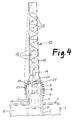
- the Fig. 1 and 4 each show in axial section the mouthpiece-side end portion of a two-component cartridge.
- the two-component cartridge after the Fig. 1 and 4 consists of an outer tube body 1 with a front end wall 2 and a mouthpiece part 3, which is provided with an external thread 4, and an inner tube body 5 with a mouthpiece part 6.
- the inner tube body 5 is arranged coaxially in the outer tube body by the mouthpiece part 6 of inner tubular body 5 is inserted into the mouthpiece part 3 of the outer tubular body 1 and locked there.
- the inner tubular body 5 forms with its inner space 7 a first chamber for receiving a first material component
- the outer tubular body 1 forms between it and the inner tubular body 5, an annular second chamber 8 for receiving a second material component.
- the mouthpiece part 6 of the inner tube body 5 forms a cylindrical outlet channel 9 for the first material component
- the mouthpiece part 3 of the outer tube body 1 forms between it and the mouthpiece part 6 of the inner tube body 5 an annular outlet channel 10 for the second material component.
- the axially rear, latched in the mouthpiece part 3 of the outer tubular body 1 portion of the mouthpiece part 6 of the inner tubular body 5 has along its circumference a plurality of passageways for connecting the annular second chamber 8 with the annular outlet channel 10, which in the drawing figures 1 and 4 are not visible, because the local section passes through the Verrastungsrippen 11 of the mouthpiece part 6 of the inner tube body 5.
- Fig. 1 and 4 differ in that in Fig. 1 a mixer 12 is screwed onto the mouthpiece assembly while in Fig. 4 a cap 13 is screwed onto the mouthpiece assembly.
- the mixer 12 has a mixing tube 14, which is widened at its inlet end to a threaded sleeve 15 which is screwed onto the external thread 4 of the mouthpiece part 3 of the outer tubular body 1, and takes in the mixing tube 14 a number of axially successive, known per se Mixing elements 16, which rotate and divide the strands of material again and again, thus causing the mixing.
- Fig. 3 shows in perspective view the front end portion of the inner tube body 5 with its mouthpiece part 6.
- Verrastungsrippen 11 and the circumferentially formed between these passageways 17 are visible in detail, which connect the second chamber 8 with the annular outlet channel 10.
- the end of the cylindrical outlet channel 9 of the mouthpiece portion 6 of the inner tubular body 5 extends in its exit end region in the form of four cross-shaped or star-shaped pocket-like extensions 18 which converge radially outwardly and, like from the Fig. 1 and 4 is visible in section, in the outlet cross-section of the annular outlet channel 10 between the mouthpiece parts 3 and 6 of the outer tubular body 1 and the inner tubular body 5 in running.
- Fig. 1 It can be seen that has the mixing elements 16 of the mixer 12 existing mixer insert at its lower, ie inlet end a central pin 19 which terminates in a knob-like central body 20, which, when the mixer 12 is placed on the mouthpiece assembly 3, 6, in the outlet end of the inner cylindrical outlet channel 9 protrudes and closes its central region, so that the first material component emerging from this outlet channel 9 is divided into four strands of material flowing obliquely radially and axially through the pocket-like extensions 18.
- the central body 20 preferably has, as shown, an upstream pointing Ablenkspitze 21, which, as shown, may be formed as an approximately cylindrical and rounded pin or conical.
- the emerging from the annular outlet channel 10 second material component is then also divided by the pocket-like extensions 18 of the outlet channel 9 in several strands of material extending between the strands of material of the first material component and obtained by each taking place in the circumferential direction marflection through the pocket-like extensions 18 a cross-directional component , which favors the immediate mixing with the material strands of the first material component.
- Fig. 1 This consists of one piece and has on its end wall 22 a molded cylindrical hollow pin 23 whose axial length is dimensioned so that when screwing the cap 13 on the external thread 4 of the mouthpiece part. 3 of the outer tubular body 1 engages in the cylindrical part of the outlet channel 9 of the mouthpiece part 6 of the inner tubular body 5 and sealingly seals it.
Abstract
Description
Zweikomponentenkartuschen für plastische Massen wie beispielsweise Dichtungsmassen, Klebstoffe, Dentalformmassen oder andere Massen sind bekannt. Sie haben zwei Kammern, die oft koaxial angeordnet sind und häufig durch zwei ineinandergesteckte koaxiale Rohrkörper gebildet sind, die mit ihren Mundstückbereichen ineinandergesteckt sind. Dabei ist eine erste Kammer durch den Innenraum des inneren Rohrkörpers gebildet und eine zweite Kammer als Ringkammer zwischen dem äußeren und dem inneren Rohrkörper gebildet. Im hinteren Bereich werden die beiden Rohrkörper durch den die äußere ringförmige Kammer abschließenden Ringkolben in ihrer koaxialen Position gehalten.Two-component cartridges for plastic compositions such as sealants, adhesives, dental molding compounds or other materials are known. They have two chambers, which are often arranged coaxially and often formed by two nested coaxial tubular body, which are nested with their mouthpiece areas. In this case, a first chamber is formed by the interior of the inner tubular body and a second chamber is formed as an annular chamber between the outer and the inner tubular body. In the rear area, the two tubular bodies are held in their coaxial position by the annular piston closing the outer annular chamber.
Die ineinandergesteckten Mundstücke der beiden Rohrkörper bilden Ausläufe für die Materialkomponenten in der inneren ersten Kammer bzw. der äußeren zweiten Kammer. Bis zum Gebrauch ist die Zweikammerkartusche durch eine Verschlusskappe verschlossen, mit der sie auch bei Arbeitsunterbrechung wiederverschließbar ist. Zum Gebrauch wird auf den Mundstückhals des äußeren Rohrkörpers ein Mischer aufgeschraubt, der ein Mischrohr aufweist, in welchem axial hintereinander eine Anzahl von Mischkörpern untergebracht ist, um die aus der ersten Kammer austretende erste Materialkomponente mit der aus der zweiten Kammer austretenden Materialkomponente möglichst schnell und möglichst homogen zu vermischen. Am Ende des Mischrohrs soll dann ein völlig homogenes Gemisch aus den beiden Materialkomponenten austreten.The nested mouthpieces of the two tubular bodies form outlets for the material components in the inner first chamber and the outer second chamber, respectively. Until use, the two-chamber cartridge is closed by a cap, with which it is resealable even when work is interrupted. For use, a mixer is screwed onto the mouthpiece neck of the outer tubular body, which has a mixing tube in which a number of mixing bodies are housed axially one behind the other, around the first material component emerging from the first chamber with the material component emerging from the second chamber as quickly as possible and as far as possible to mix homogeneously. At the end of the mixing tube then a completely homogeneous mixture of the two material components should emerge.
Die bei solchen Zweikomponentenkartuschen auftretenden Probleme sind bekannt und werden seit langem bearbeitet.The problems encountered with such two-component cartridges are well known and have long been addressed.
Das eine Problem ist die Sicherstellung, dass die beiden Materialkomponenten vor dem Anbrechen der Zweikomponentenkartusche vollkommen getrennt sind und nicht miteinander in Berührung kommen können, um ein vorzeitiges Reagieren der beiden Materialkomponenten miteinander und deren Abbinden oder Aushärten zu vermeiden. Dazu ist es notwendig, dass die Verschlusskappe zum einen die Mundstückanordnung der beiden Rohrkörper insgesamt absolut dicht verschließt, und dass die Verschlusskappe außerdem eine vollkommen abdichtende Trennung der Ausläufe aus der ersten Kammer und der zweiten Kammer herstellt.The one problem is to ensure that the two components of the material are completely separate from each other before the two-component cartridge is broken and can not come into contact with one another to prevent premature reaction of the two components with each other and their setting or curing. For this purpose, it is necessary that the cap on the one hand, the mouthpiece assembly of the two tubular body as a whole closes absolutely tight, and that the cap also makes a completely sealing separation of the outlets from the first chamber and the second chamber.
Das zweite Problem ist die Ausgestaltung des Mischsystems derart, dass ein homogenes Vermischen der beiden Materialkomponenten mit einem möglich wenige Mischelemente enthaltenden, möglicht kurzen Mischrohr ermöglicht wird, weil der notwendige Auspressdruck der Zweikomponentenkartusche natürlich umso größer ist, je größer die Anzahl der axial aufeinanderfolgenden Mischelemente im Mischrohr ist, denn jedes weitere Mischelement vergrößert den Strömungswiderstand. Dieses Problem ist umso bedeutsamer, je zähflüssiger die auszupressenden und zu mischenden Materialkomponenten sind.The second problem is the design of the mixing system such that a homogeneous mixing of the two material components with a possible few mixing elements containing possible short mixing tube is made possible, because the necessary extrusion pressure of the two-component cartridge, of course, the greater, the greater the number of axially successive mixing elements in Mixing tube is, because every other mixing element increases the flow resistance. This problem is all the more significant the more viscous the material components to be squeezed out and mixed are.
Um den auf die Mundstückanordnung der Zweikomponentenkartusche aufzuschraubenden Mischer möglichst kurz und mit möglichst wenigen Mischelementen ausbilden zu können, ist man bestrebt, die beiden Materialkomponenten schon in der Mundstückanordnung in eine Mehrzahl von Fließsträngen aufzuteilen, die dann in das Eintrittsende des Mischers eintreten, um den Mischvorgang zu beschleunigen.In order to be able to form the mixer to be screwed onto the mouthpiece arrangement of the two-component cartridge as short as possible and with as few mixing elements as possible, it is endeavored to divide the two material components already in the mouthpiece arrangement into a plurality of flow strands, which then enter the inlet end of the mixer in order to effect the mixing process to accelerate.
Zu diesem Zweck ist es aus der
Dazu ist der Mundstückteil des inneren Rohrkörpers, der in den Mundstückteil des äußeren Rohrkörpers eingesteckt ist, mit einer kranzartigen Anordnung separater segmentförmiger oder zylindrischer Austrittskanäle ausgebildet, die sternartig im Mundstückteil des äußeren Rohrkörpers sitzen, wobei die umfangsmäßigen Zwischenräume zwischen den einzelnen Austrittskanälen des Mundstückteils des inneren Rohrkörpers, welche die Auslaufkanäle für die erste Materialkomponente bilden, die Auslaufkanäle für die zweite Materialkomponente bilden. Die in Umfangsrichtung miteinander abwechselnden Materialstränge der ersten Materialkomponente und der zweiten Materialkomponente treten dann als paralleles Strangbündel in das Eintrittsende des Mischers ein.For this purpose, the mouthpiece portion of the inner tube body, which is inserted into the mouthpiece portion of the outer tube body, formed with a coronary arrangement of separate segmental or cylindrical outlet channels, the star-like sitting in the mouthpiece portion of the outer tubular body, wherein the circumferential spaces between the individual outlet channels of the mouthpiece portion of the inner Pipe body, which form the outlet channels for the first material component, forming the outlet channels for the second material component. The material strands of the first material component and the second material component which alternate in the circumferential direction then enter into the inlet end of the mixer as a parallel strand bundle.
Bei dieser bekannten Anordnung erscheinen zwei Dinge nachteilig.In this known arrangement, two things appear disadvantageous.
Das eine ist der Umstand, dass die Materialstränge der ersten Materialkomponente und der zweiten Materialkomponente genau parallel in das Einlassende des Mischers einströmen, weil sie über die ganze Länge der Mundstückanordnung durch die dort gebildeten Auslaufkanäle parallel geführt werden, so dass mangels irgendeiner vorhandenen Querströmungskomponente in den Materialsträngen die Mischung erst durch das erste Mischelement im Mischer eingeleitet wird.One is the fact that the strands of material of the first material component and the second material component flow exactly parallel into the inlet end of the mixer, because they are guided parallel over the entire length of the mouthpiece arrangement by the outlet channels formed there, so that in the absence of any existing cross-flow component in the Material strands the mixture is first introduced through the first mixing element in the mixer.
Das zweite ist der Umstand, dass die Verschlusskappe jeden der Auslaufkanäle des Mundstückteils des inneren Rohrkörpers einzeln verschließen muß und dazu einen in den jeweiligen Auslaufkanal eingreifenden und dicht schließenden Zapfen haben muß. Dabei ist die Dichtigkeit selbst bei einem Kranz von zylindrischen Zapfen für zylindrische Auslaufkanäle nur schwer zu erreichen und bei im Querschnitt ringsegmentförmigen Austrittskanälen noch bedeutend schwerer zu erreichen. In jedem Fall muß die Verschlusskappe zweiteilig ausgebildet sein und einen inneren Stopfenteil haben, an dem die in die Auslaufkanäle eingreifenden Verschlusszapfen gebildet sind, und eine Schraubhülse haben, die auf den Mundstückhals des äußeren Rohrkörpers aufschraubbar ist.The second is the circumstance that the closure cap must individually close each of the outlet channels of the mouthpiece part of the inner tube body and for this purpose must have a pin engaging in the respective outlet channel and sealingly closing. The tightness is difficult to achieve even with a wreath of cylindrical pin for cylindrical outlet channels and even more difficult to achieve in cross-sectionally annular outlet channels. In any case, the closure cap must be formed in two parts and have an inner plug part, on which the locking channels engaging in the outlet channels are formed, and have a threaded sleeve which can be screwed onto the mouthpiece neck of the outer tubular body.
Aufgabe der Erfindung ist es, eine Anordnung zu schaffen, die hinsichtlich beider Probleme eine deutliche Verbesserung bringt.The object of the invention is to provide an arrangement which brings a significant improvement in both problems.
Diese Aufgabe wird gemäß der Erfindung durch die im Anspruch 1 angegebene Anordnung gelöst. Vorteilhafte Ausgestaltungen der Erfindung sind Gegenstand der Unteransprüche.This object is achieved according to the invention by the arrangement specified in
Die erfindungsgemäße Anordnung verkörpert ein Mischsystem, dessen entscheidende Merkmale teils im Mundstückbereich der Zweikomponentenkartusche und teils im Mischer vorgesehen sind, und die beim Aufsetzen des Mischers auf die Mundstückanordnung miteinander vorteilhaft zusammenwirken.The arrangement according to the invention embodies a mixing system whose decisive features are provided partly in the mouthpiece region of the two-component cartridge and partly in the mixer, and which advantageously cooperate with one another when the mixer is placed on the mouthpiece arrangement.
Die erfindungsgemäße Anordnung besteht im wesentlichen darin, dass sich ein einziger, etwa zylindrischer Auslaufkanal des Mundstückteils des inneren Rohrkörpers erst an seinem Austrittsende in Gestalt einer kranzartigen Anordnung von mehreren auswärts divergierenden taschenartigen Erweiterungen erweitert, die in den Lichtquerschnitt des ringförmig um diesen Auslaufkanal für die erste Materialkomponente verlaufenden Auslaufkanal für die zweite Materialkomponente im Mundstückteil des äußeren Rohrkörpers hineinverlaufen. Der Mischer hat an seinem Eintrittsende vor dem ersten Mischelement einen knaufartige geformten Zentralkörper, der vorzugsweise mit einer entgegen der Materialströmungsrichtung weisenden Ablenkspitze ausgebildet ist, und der, wenn der Mischer auf die Mundstückanordnung aufgesetzt ist, in das Auslaufende des Auslaufkanals für die erste Materialkomponente (im Innenraum des ersten Rohrkörpers) hineinragt und bewirkt, dass die durch den etwa zylindrischen Auslaufkanal austretende erste Materialkomponente radial auswärts in die taschenartigen Erweiterungen abgelenkt wird und dadurch eine Mehrzahl von Materialsträngen bildet, die mit einer Axialkomponente und einer radial auswärts divergierenden Richtungskomponente verlaufen. Die durch den ringförmigen Ausströmkanal zwischen den Mundstückteilen des inneren Rohrkörpers und des äußeren Rohrkörpers ausströmende zweite Materialkomponente wird durch die Strömungshindernisse, welche durch die taschenartigen Erweiterungen des Austrittskanals der ersten Materialkomponente gebildet sind, ebenfalls in mehrere Materialstränge aufgeteilt, die in Umfangsrichtung abwechselnd mit den durch die taschenartigen Erweiterungen austretenden Materialsträngen der ersten Materialkomponente angeordnet sind. Durch diese Strömunsgablenkung der zweiten Materialkomponente durch die taschenartigen Erweiterungen des inneren Austrittskanals für die erste Materialkomponente erfährt die zweite Materialkomponente aber eine jeweils seitliche Strömungsablenkung, weshalb die Materialstränge der zweiten Materialkomponente mit Umfangsrichtungskomponenten behaftet sind und dadurch sogleich eine Vermischung mit den Materialsträngen der ersten Materialkomponente stattfindet, noch bevor die Materialstränge das erste Mischelement im Mischrohr des Mischers erreichen.The arrangement according to the invention consists essentially in that a single, approximately cylindrical outlet channel of the mouthpiece part of the inner tubular body extends only at its outlet end in the form of a coronary arrangement of several outwardly diverging pocket-like extensions in the light cross section of the annular to this outlet channel for the first Material component extending outlet channel for the second material component in the mouthpiece part of the outer tube body. The mixer has at its inlet end in front of the first mixing element a knob-like shaped central body, which is preferably formed with a counter-flow direction pointing Ablenkspitze, and which, when the mixer is placed on the mouthpiece assembly in the outlet end of the outlet channel for the first material component (in Interior of the first tubular body) protrudes and causes the emerging through the approximately cylindrical outlet channel first material component is deflected radially outwardly into the pocket-like extensions and thereby forms a plurality of strands of material which extend with an axial component and a radially outwardly diverging direction component. The flowing through the annular outflow between the mouthpiece parts of the inner tube body and the outer tube body second material component is also divided by the flow obstacles, which are formed by the pocket-like extensions of the outlet channel of the first material component in several strands of material alternately in the circumferential direction with those through the pocket-like expansions emerging material strands of the first material component are arranged. As a result of this flow deflection of the second material component through the pocket-like extensions of the inner outlet channel for the first material component, the second material component, however, experiences a respective lateral flow deflection, for which reason the material strands of the second material component associated with circumferential direction components and thereby immediately takes place mixing with the material strands of the first material component, even before the strands of material reach the first mixing element in the mixing tube of the mixer.
Die erfindungsgemäße Anordnung ermöglicht eine deutliche Reduzierung der Anzahl der Mischelemente im Mischrohr des Mischers zur Erzielung einer homogenen Vermischung der beiden Materialkomponenten und eine ganz erhebliche Reduzierung des notwendigen Auspressdrucks. Dies beruht auf folgenden Vorteilen:The inventive arrangement allows a significant reduction in the number of mixing elements in the mixing tube of the mixer to achieve a homogeneous mixing of the two material components and a very significant reduction of the necessary extrusion pressure. This is due to the following advantages:
Innerhalb der Mundstückanordnung strömen sowohl die erste Materialkomponente als auch die zweite Materialkomponente durch große gleich bleibende Öffnungsquerschnitte, bis zu der Stelle, an welcher sich der innere Austrittskanal für die erste Materialkomponente in Gestalt der kranzartig angeordneten taschenartigen Erweiterungen in den ringförmigen Strömungskanal für die zweite Materialkomponente erweitert. Dort verengt sich durch den knaufartigen Zentralkörper im Eintrittsbereich des Mischers der Gesamtströmungsquerschnitt etwas, wodurch sich eine Intensivierung der Vorvermischung aufgrund der nicht nur axialen Richtungskomponenten, sondern auch der vorhandenen Umfangsrichtungskomponenten der Strömungen einstellt. Dieser Bereich der Querschnittsverminderung ist allerdings axial sehr kurz, weshalb auch der dadurch induzierte Strömungswiderstand niedrig ist. Der nachfolgende Mischvorgang bis zum Erreichen einer homogenen Mischung der beiden Materialkomponenten erfordert dann nur noch eine relativ geringe Anzahl von Mischelementen im Mischrohr.Within the mouthpiece assembly, both the first material component and the second material component flow through large, uniform opening cross-sections, up to the point where the inner exit passage for the first material component in the shape of the coronary pocket-like extensions widens into the annular flow passageway for the second material component , There narrowed by the knob-like central body in the inlet region of the mixer, the total flow area something, which sets an intensification of the premixing due to the not only axial direction components, but also the existing circumferential direction components of the currents. However, this area of the cross-sectional reduction is axially very short, which is why the flow resistance induced thereby is low. The subsequent mixing process until reaching a homogeneous mixture of the two material components then only requires a relatively small number of mixing elements in the mixing tube.
Die Erfindung bringt damit einen ganz erheblichen Vorteil im Hinblick auf die Effizienz der durch Mischung der beiden Materialkomponenten, der Anzahl der erforderlichen Mischelemente im Mischrohr, und folglich eine sehr deutliche Reduzierung des notwendigen Auspressdrucks, was besonders bei zähfließenden Massen einen großen Vorteil bringt.The invention thus brings a very significant advantage in terms of the efficiency of mixing the two material components, the number of mixing elements required in the mixing tube, and consequently a very significant reduction of the necessary extrusion pressure, which brings a great advantage especially for viscous masses.
Außerdem vereinfacht die erfindungsgemäße Anordnung die Ausbildung der Verschlusskappe und deren Abdichtungssicherheit ganz erheblich. Weil der innere Austrittskanal für die erste Materialkomponente zylindrisch und zentrisch angeordnet ist und nur ein solcher Kanal vorhanden ist, kann die Verschlusskappe einteilig ausgebildet sein und einen einzigen mittigen Stopfen haben, der in den zylindrischen Teil des Austrittskanals für die erste Materialkomponente eingreift und diesen absolut dicht verschließt.In addition, the arrangement according to the invention greatly simplifies the design of the closure cap and its sealing safety. Because the inner outlet channel for the first material component is arranged cylindrically and centrically and only one such channel is present, the closure cap can be integrally formed and a single have central plug, which engages in the cylindrical part of the outlet channel for the first material component and closes this absolutely tight.
Ein Ausführungsbeispiel der Erfindung ist in den anliegenden Zeichnungen dargestellt und wird im folgenden mehr im einzelnen beschrieben. In den Zeichnungen zeigt:
- Fig. 1
- einen Axialschnitt durch den Mundstück- bereich einer Zweikomponentenkartusche und einen aufgesetzten Mischer mit einem Misch- system nach der Erfindung,
- Fig. 2
- eine perspektivische Ansicht des Innenrohr- körpers mit seinem Mundstückbereich der in
Fig. 1 gezeigten Zweikomponentenkar- tusche, - Fig. 3
- eine vergrößerte perspektivische Darstellung der Einzelheit III in
Fig. 2 , und - Fig. 4
- einen Axialschnitt durch den Mundstück- bereich der in
Fig. 1 dargestellten Zweikompo- nentenkartusche, jedoch mit aufgesetzter Ver- schlußkappe.
- Fig. 1
- an axial section through the mouthpiece area of a two-component cartridge and a mounted mixer with a mixing system according to the invention,
- Fig. 2
- a perspective view of the Innenrohr- body with its mouthpiece portion of in
Fig. 1 shown two-component cartridge, - Fig. 3
- an enlarged perspective view of the detail III in
Fig. 2 , and - Fig. 4
- an axial section through the mouthpiece area of in
Fig. 1 shown two-component cartridge, but with attached cap.
Die
Der Mundstückteil 6 des inneren Rohrkörpers 5 bildet einen zylindrischen Austrittskanal 9 für die erste Materialkomponente, und der Mundstückteil 3 des äußeren Rohrkörpers 1 bildet zwischen sich und dem Mundstückteil 6 des inneren Rohrkörpers 5 einen ringförmigen Austrittskanal 10 für die zweite Materialkomponente. Es versteht sich, dass der axial rückwärtige, im Mundstückteil 3 des äußeren Rohrkörpers 1 verrastete Abschnitt des Mundstückteils 6 des inneren Rohrkörpers 5 entlang seines Umfangs mehrere Durchtrittskanäle zur Verbindung der ringförmigen zweiten Kammer 8 mit dem ringförmigen Austrittskanal 10 aufweist, die in den Zeichnungsfiguren 1 und 4 nicht sichtbar sind, weil der dortige Schnitt durch die Verrastungsrippen 11 des Mundstückteils 6 des inneren Rohrkörpers 5 verläuft.The
Die
Der Mischer 12 weist ein Mischrohr 14 auf, das an seinem eintrittsseitigen Ende zu einer Schraubhülse 15 erweitert ist, die auf das Außengewinde 4 des Mundstückteils 3 des äußeren Rohrkörpers 1 aufschraubbar ist, und nimmt im Mischrohr 14 eine Anzahl von axial aufeinanderfolgenden, an sich bekannten Mischelementen 16 auf, welche die Materialstränge immer wieder verdrehen und aufteilen und so die Durchmischung bewirken.The
Die in
Wie aus
Die aus den ringförmigen Austrittskanal 10 austretende zweite Materialkomponente wird dann durch die taschenartigen Erweiterungen 18 des Austrittskanals 9 ebenfalls in mehrere Materialstränge aufgeteilt, die zwischen den Materialsträngen der ersten Materialkomponente verlaufen und durch die jeweils in Umfangsrichtung erfolgende seitwärtige Ablenkung durch die taschenartigen Erweiterungen 18 eine Querrichtungskomponente erhalten, was die sofortige Durchmischung mit den Materialsträngen der ersten Materialkomponente begünstigt.The emerging from the
Claims (5)
dadurch gekennzeichnet, dass der zentrale Austrittskanal (9) sich in seinem austrittsseitigen Endbereich durch sternförmig angeordnete, taschenartig ausgebildete Erweiterungen (18) in den ringförmigen äußeren Austrittskanal (10) hinein erweitert, und dass der Mischer in seinem eintrittsseitigen Endbereich einen Zentralkörper (20) enthält, der, wenn der Mischer (12) auf die Mundstückanordnung (3, 6) aufgesetzt ist, den zentralen Querschnittsbereich des zentralen Austrittskanals (9) im wesentlichen verschließt.A two-component plastic cartridge mixing system, the two-component cartridge (1,5) having a mouthpiece assembly having an inner mouthpiece portion (6) and an outer mouthpiece portion (3), the inner mouthpiece portion (6) having an inner, approximately cylindrical, outlet channel (10). for a first material component of a first chamber (7) and forms the outer mouthpiece part (3) between them and the inner mouthpiece part (6) an annular outlet channel (10) for a second material component of a second chamber, and wherein the mouthpiece assembly Mixer (12) with a mixing tube (14) is placed, in which axially successively a plurality of mixing elements (16) is arranged, and wherein the mouthpiece assembly means (18) for dividing the streams of material of the first material component and the second material component in a number of coronal and alternately arranged strands of material comprising the first and second material components,
characterized in that the central outlet channel (9) widens in its outlet-side end region by star-shaped pocket-like extensions (18) into the annular outer outlet channel (10), and in that the mixer contains a central body (20) in its inlet-side end region which, when the mixer (12) is placed on the mouthpiece assembly (3, 6) substantially closes off the central cross-sectional area of the central outlet channel (9).
Priority Applications (3)
| Application Number | Priority Date | Filing Date | Title |
|---|---|---|---|
| EP09007452A EP2258466A1 (en) | 2009-06-05 | 2009-06-05 | Mixing system for dual component cartridges |
| EP10005821A EP2258468B1 (en) | 2009-06-05 | 2010-06-04 | Mixing system for dual component cartridges |
| US12/802,446 US8894270B2 (en) | 2009-06-05 | 2010-06-07 | Mixing system for two-component cartridge |
Applications Claiming Priority (1)
| Application Number | Priority Date | Filing Date | Title |
|---|---|---|---|
| EP09007452A EP2258466A1 (en) | 2009-06-05 | 2009-06-05 | Mixing system for dual component cartridges |
Publications (1)
| Publication Number | Publication Date |
|---|---|
| EP2258466A1 true EP2258466A1 (en) | 2010-12-08 |
Family
ID=41254671
Family Applications (1)
| Application Number | Title | Priority Date | Filing Date |
|---|---|---|---|
| EP09007452A Withdrawn EP2258466A1 (en) | 2009-06-05 | 2009-06-05 | Mixing system for dual component cartridges |
Country Status (1)
| Country | Link |
|---|---|
| EP (1) | EP2258466A1 (en) |
Cited By (3)
| Publication number | Priority date | Publication date | Assignee | Title |
|---|---|---|---|---|
| GB2484694A (en) * | 2010-10-20 | 2012-04-25 | Chemfix Products Ltd | Mixing extruded materials |
| EP2764909A2 (en) | 2013-02-08 | 2014-08-13 | CHEMOFAST Anchoring GmbH | Mixing device for two-component cartridges |
| US8899446B2 (en) | 2010-04-28 | 2014-12-02 | Integra Adhesives Inc. | Apparatus for mixing and dispensing multiple flowable components |
Citations (3)
| Publication number | Priority date | Publication date | Assignee | Title |
|---|---|---|---|---|
| DE9207048U1 (en) * | 1992-05-25 | 1992-07-30 | Chemofast Korte-Jungermann Gmbh & Co Kg, 4156 Willich, De | |
| DE20316879U1 (en) * | 2003-10-31 | 2005-03-17 | Sulzer Chemtech Ag Winterthur | Coaxial two-component cartridge |
| WO2005095225A1 (en) | 2004-04-01 | 2005-10-13 | 5 Mix Limited | Dispenser for two components and method for dispensing first and second components |
-
2009
- 2009-06-05 EP EP09007452A patent/EP2258466A1/en not_active Withdrawn
Patent Citations (3)
| Publication number | Priority date | Publication date | Assignee | Title |
|---|---|---|---|---|
| DE9207048U1 (en) * | 1992-05-25 | 1992-07-30 | Chemofast Korte-Jungermann Gmbh & Co Kg, 4156 Willich, De | |
| DE20316879U1 (en) * | 2003-10-31 | 2005-03-17 | Sulzer Chemtech Ag Winterthur | Coaxial two-component cartridge |
| WO2005095225A1 (en) | 2004-04-01 | 2005-10-13 | 5 Mix Limited | Dispenser for two components and method for dispensing first and second components |
Cited By (5)
| Publication number | Priority date | Publication date | Assignee | Title |
|---|---|---|---|---|
| US8899446B2 (en) | 2010-04-28 | 2014-12-02 | Integra Adhesives Inc. | Apparatus for mixing and dispensing multiple flowable components |
| GB2484694A (en) * | 2010-10-20 | 2012-04-25 | Chemfix Products Ltd | Mixing extruded materials |
| GB2484694B (en) * | 2010-10-20 | 2012-11-14 | Chemfix Products Ltd | Mixing extruded materials |
| EP2764909A2 (en) | 2013-02-08 | 2014-08-13 | CHEMOFAST Anchoring GmbH | Mixing device for two-component cartridges |
| DE102013002290A1 (en) | 2013-02-08 | 2014-08-28 | Chemofast Anchoring Gmbh | Mixing device for two-component cartridges |
Similar Documents
| Publication | Publication Date | Title |
|---|---|---|
| EP1110599B1 (en) | Dynamic mixer for dental impression pastes | |
| EP2599540B1 (en) | Mixing element for a static mixer and its use | |
| EP1099470B1 (en) | Device for mixing two pasty materials, especially for mixing a dental impression material with a catalyst material | |
| EP2848320B1 (en) | Connector for connecting a storage container to a static mixer | |
| DE102015002974A1 (en) | Device for the aftertreatment of exhaust gas of a motor vehicle | |
| EP1328338B1 (en) | Static mixer and method for mixing a main component with an additional component | |
| EP2618921B1 (en) | Mixer | |
| EP2527029B1 (en) | Static mixer | |
| EP2258468B1 (en) | Mixing system for dual component cartridges | |
| DE202012013429U1 (en) | Cartridge system and static mixer for this | |
| DE102004008748A1 (en) | Dynamic mixer, used for mixing components of dentistry compositions, comprises mixing tube, rotor delimiting annular mixing channel, and wall with inlet openings for components | |
| EP2286925B1 (en) | Static spray mixer | |
| EP2548635B1 (en) | Dynamic mixer with a seal | |
| EP0303590B1 (en) | Device for spraying the outside of a core, especially one of an electric conductor | |
| DE10347938A1 (en) | Head part for a multi-compartment hose bag | |
| EP2258466A1 (en) | Mixing system for dual component cartridges | |
| DE202009007919U1 (en) | Mixing system for two-component cartridge | |
| DE102016122041A1 (en) | Multicomponent container | |
| DE102017117199A1 (en) | Mixer with compensation channel and / or stowage chamber | |
| EP2764909A2 (en) | Mixing device for two-component cartridges | |
| DE102008013083B4 (en) | Integrally produced multicomponent cartridge | |
| DE102012003390B4 (en) | Cartridge system and static mixer for this | |
| EP3658266B1 (en) | Mixer with compensation channel and/or accumulation chamber | |
| AT506577A4 (en) | STATIC MIXING DEVICE | |
| EP3077094B1 (en) | Dynamic mixer and use thereof |
Legal Events
| Date | Code | Title | Description |
|---|---|---|---|
| PUAI | Public reference made under article 153(3) epc to a published international application that has entered the european phase |
Free format text: ORIGINAL CODE: 0009012 |
|
| AK | Designated contracting states |
Kind code of ref document: A1 Designated state(s): AT BE BG CH CY CZ DE DK EE ES FI FR GB GR HR HU IE IS IT LI LT LU LV MC MK MT NL NO PL PT RO SE SI SK TR |
|
| AX | Request for extension of the european patent |
Extension state: AL BA RS |
|
| STAA | Information on the status of an ep patent application or granted ep patent |
Free format text: STATUS: THE APPLICATION IS DEEMED TO BE WITHDRAWN |
|
| 18D | Application deemed to be withdrawn |
Effective date: 20110609 |