EP3075574A1 - Actionneur - Google Patents
Actionneur Download PDFInfo
- Publication number
- EP3075574A1 EP3075574A1 EP15162026.7A EP15162026A EP3075574A1 EP 3075574 A1 EP3075574 A1 EP 3075574A1 EP 15162026 A EP15162026 A EP 15162026A EP 3075574 A1 EP3075574 A1 EP 3075574A1
- Authority
- EP
- European Patent Office
- Prior art keywords
- component
- fluid passage
- actuator
- rotatable
- tyre
- Prior art date
- Legal status (The legal status is an assumption and is not a legal conclusion. Google has not performed a legal analysis and makes no representation as to the accuracy of the status listed.)
- Granted
Links
- 239000012530 fluid Substances 0.000 claims abstract description 106
- 238000007789 sealing Methods 0.000 claims abstract description 47
- 238000000034 method Methods 0.000 claims description 3
- 239000013536 elastomeric material Substances 0.000 claims description 2
- 239000000463 material Substances 0.000 claims 1
- 239000000853 adhesive Substances 0.000 description 3
- 230000001070 adhesive effect Effects 0.000 description 3
- 230000006835 compression Effects 0.000 description 2
- 238000007906 compression Methods 0.000 description 2
- 230000003247 decreasing effect Effects 0.000 description 2
- 230000006866 deterioration Effects 0.000 description 2
- 239000012858 resilient material Substances 0.000 description 1
Images


Classifications
-
- B—PERFORMING OPERATIONS; TRANSPORTING
- B60—VEHICLES IN GENERAL
- B60C—VEHICLE TYRES; TYRE INFLATION; TYRE CHANGING; CONNECTING VALVES TO INFLATABLE ELASTIC BODIES IN GENERAL; DEVICES OR ARRANGEMENTS RELATED TO TYRES
- B60C29/00—Arrangements of tyre-inflating valves to tyres or rims; Accessories for tyre-inflating valves, not otherwise provided for
-
- B—PERFORMING OPERATIONS; TRANSPORTING
- B60—VEHICLES IN GENERAL
- B60C—VEHICLE TYRES; TYRE INFLATION; TYRE CHANGING; CONNECTING VALVES TO INFLATABLE ELASTIC BODIES IN GENERAL; DEVICES OR ARRANGEMENTS RELATED TO TYRES
- B60C23/00—Devices for measuring, signalling, controlling, or distributing tyre pressure or temperature, specially adapted for mounting on vehicles; Arrangement of tyre inflating devices on vehicles, e.g. of pumps or of tanks; Tyre cooling arrangements
- B60C23/001—Devices for manually or automatically controlling or distributing tyre pressure whilst the vehicle is moving
- B60C23/003—Devices for manually or automatically controlling or distributing tyre pressure whilst the vehicle is moving comprising rotational joints between vehicle-mounted pressure sources and the tyres
- B60C23/00345—Details of the rotational joints
-
- B—PERFORMING OPERATIONS; TRANSPORTING
- B60—VEHICLES IN GENERAL
- B60C—VEHICLE TYRES; TYRE INFLATION; TYRE CHANGING; CONNECTING VALVES TO INFLATABLE ELASTIC BODIES IN GENERAL; DEVICES OR ARRANGEMENTS RELATED TO TYRES
- B60C23/00—Devices for measuring, signalling, controlling, or distributing tyre pressure or temperature, specially adapted for mounting on vehicles; Arrangement of tyre inflating devices on vehicles, e.g. of pumps or of tanks; Tyre cooling arrangements
- B60C23/001—Devices for manually or automatically controlling or distributing tyre pressure whilst the vehicle is moving
- B60C23/003—Devices for manually or automatically controlling or distributing tyre pressure whilst the vehicle is moving comprising rotational joints between vehicle-mounted pressure sources and the tyres
- B60C23/00354—Details of valves
-
- B—PERFORMING OPERATIONS; TRANSPORTING
- B60—VEHICLES IN GENERAL
- B60C—VEHICLE TYRES; TYRE INFLATION; TYRE CHANGING; CONNECTING VALVES TO INFLATABLE ELASTIC BODIES IN GENERAL; DEVICES OR ARRANGEMENTS RELATED TO TYRES
- B60C23/00—Devices for measuring, signalling, controlling, or distributing tyre pressure or temperature, specially adapted for mounting on vehicles; Arrangement of tyre inflating devices on vehicles, e.g. of pumps or of tanks; Tyre cooling arrangements
- B60C23/001—Devices for manually or automatically controlling or distributing tyre pressure whilst the vehicle is moving
- B60C23/003—Devices for manually or automatically controlling or distributing tyre pressure whilst the vehicle is moving comprising rotational joints between vehicle-mounted pressure sources and the tyres
- B60C23/00363—Details of sealings
Definitions
- the present invention relates to an actuator for a tyre inflation system, for example tyre inflation systems whereby air may be supplied to a rotating pneumatic tyre via a rotating air passage which is coupled to a non-rotating air passage.
- US 4,705,090 discloses a prior art tyre inflation system which attempts to overcome this problem by providing a sealing arrangement between the rotating and non-rotating passages that includes a displaceable seal on the non-rotating component that is normally maintained out of contact with the rotating component.
- the displaceable seal can be moved into engagement with the rotating component by air under pressure from a first air line.
- This system requires the provision of a second air line for the supply of air to a vehicle tyre once the seal is in the engaged position. Significantly, air from the first air line is not supplied to the vehicle tyre.
- US 4,892,128 describes a less complex tyre inflation system with a single air line which has seals between the rotating and non-rotating components that are lightly engaged in normal use.
- air within the pressure control system is used to bring the seal members into heavy engagement, air from the same line then being supplied to the tyre.
- this actuation system is simpler than that of US 4,705,090 , it suffers the aforementioned disadvantage of permanent contact friction between the seals, subsequent deterioration of the seals and power loss.
- An object of the present invention is to provide an actuator for a tyre inflation assembly whereby power loss is reduced, and/or component life is increased and/or the actuation system is simplified.
- an actuator for a tyre inflation system having a first component having a first fluid passage and a second component having a second fluid passage and a sealing surface for sealing engagement with a rotatable component of a wheel assembly, the second component being movable relative to the first component between a first position where the first fluid passage is isolated from the second fluid passage and the sealing surface is spaced from the rotatable component and a second position where the first fluid passage is in fluid communication with the second fluid passage and the sealing surface is in sealing engagement with the rotatable component.
- This actuator arrangement is particularly advantageous as it employs a single air line, the supply of air from which can be used to both engage the seals and supply air to the tyre.
- the second component may move axially relative to the first component.
- the first fluid passage may be isolated from the second fluid passage by virtue of engagement between the first component and the second component.
- the actuator may include a protrusion of one of the first component or the second component that engages the other of the first component or the second component to isolate the first component and the second component.
- the protrusion may be on the first component.
- the first component may include an inlet for supplying a fluid to the first fluid passage.
- the first component may have a single inlet for supplying a fluid to the first fluid passage.
- the second component may be movable to the second position in response to an increase in pressure in the first fluid passage.
- the second component may be movable to the second position in response to fluid supplied to the first fluid passage exerting pressure on a face of the second component.
- the cross-sectional area of the face on which the pressure is exerted may be substantially greater than the cross-sectional area of the second fluid passage.
- a single fluid source may be used for moving the second component relative to the first component and supplying fluid to the tyre inflation system.
- Fluid may be supplied through the first fluid passage, moving the second component to the second position, the fluid passing via the second fluid passage to a tyre to be inflated.
- the second component may include a first bearing having an axis that is offset relative to an axis of the rotatable component, for example the axis of rotation of the rotatable component, e.g. to reduce friction between the first component and the second component when the second component moves relative to the first component.
- the second component may include a second bearing having an axis that is co-incident with an axis of the rotatable component, for example the axis of rotation of the rotatable component, e.g. to reduce friction between the first component and the second component when the second component moves relative to the first component.
- the second component may include a body, the sealing surface being resiliently mounted relative to the body.
- the resilient mounting may be provided by an elastomeric, for example rubber-like, member.
- the actuator may include a bias device that biases the sealing surface of the second component away from the rotatable component.
- the actuator may have a plurality of bias devices arranged around an annulus to bias the sealing surface of the second component away from the rotatable component.
- the bias devices may be spaced equally around the annulus, for example at 120° relative to the other bias devices.
- the actuator may include a pin to prevent rotation of the first component relative to the second component.
- the actuator may include a plurality of pins to prevent rotation of the first component relative to the second component.
- the pins may be spaced equally around the annulus, for example at 120° relative to the other pins.
- the one or more pins may each be associated with a bias device.
- a system for changing a pressure in a tyre including an actuator according to claim 1 and a rotatable component having a rotatable fluid passage, a rotatable sealing surface arrangement and being rotabably fast to a wheel, the sealing surface being selectively engagable with the rotatable sealing surface arrangement to selectively fluidly connect the first fluid passage to the rotatable fluid passage.
- a method of changing a pressure in a tyre including providing a vehicle with a tyre; providing a rotatable component having a rotatable fluid passage connected to the tyre, a rotatable sealing surface arrangement and being rotabably fast to the tyre; providing an actuator according to claim 1 that is selectively engagable with the rotatable sealing surface arrangement to selectively fluidly connect the first fluid passage and the rotatable fluid passage; operably connecting the rotatable fluid passage to the tyre; and changing a pressure in the actuator to change pressure in the tyre by passing fluid through the first fluid passage, then through the second fluid passage, then through the rotatable fluid passage.
- the pressure in the tyre may advantageously be changed while the vehicle is moving.
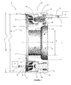
- a tyre inflation system 5 having a pressurised air supply 10 (shown schematically), an actuator 20, a wheel hub 30, a wheel spindle 40 and a tyre 15 (shown schematically).
- the pressurised air supply 10 has a fluid passage 12.
- the fluid passage 12 has a valve 8.
- the tyre 15 has a valve 18, for example a schrader valve.
- the wheel hub 30 has an axis A, about which it can rotate, a flange 32 that has an outer cylindrical surface 31, a generally flat annular surface 34, and a fluid passage 36 that has an inlet 38 on the generally flat surface 34.
- the wheel spindle 40 has an axis A, about which it is held stationary, a first portion 42 having an outer cylindrical surface 44 and a diameter B, a second portion 46 having an outer cylindrical surface 48 and a diameter C, and a shoulder 50 between the first portion 42 and the second portion 46.
- the actuator 20 has a first component 22 and a second component 24.
- the first component 22 is generally annular and has an axis A, about which it is held stationary, an outer cylindrical surface 52 having a diameter D, a first inner cylindrical surface 54, a second inner cylindrical surface 55, a first flat annular surface 60 at a first axial position and a second flat annular surface 61 at a second axial position.
- the first component 22 has a generally annular recess 58.
- the recess 58 has a cylindrical outer wall 62, a cylindrical inner wall 64 and a flat annular surface 66.
- the recess 58 has a width E.
- the first component 22 has a through hole 68 having an axis G that extends from a generally flat annular surface 70 to the flat annular surface 66.
- the hole 68 is a stepped hole having a first diameter R, a second diameter F and a third diameter H .
- the hole 68 has a step 71 between the first diameter R and the second diameter F and a second step 72 between the second diameter F and the third diameter H.
- Axis G is spaced from axis A by a distance S.
- the first component 22 has a second through hole 76a having an axis K (see figure 4 ) that extends from the flat annular surface 70 to the generally flat annular surface 66.
- the hole 76a is a stepped hole having a first diameter J and a second diameter L.
- the hole 76a has a step 78 between the first diameter J and the second diameter L.
- Axis K is spaced from axis A by a distance T.
- the first component 22 has two further holes 76b, 76c.
- the third and fourth holes 76b, 76c are the same shape as the second hole 76a and have axes M and N, respectively.
- Axes K, M and N are parallel to each other.
- Axes M and N are each spaced from axis A by a distance T.
- the three holes 76a, 76b and 76c are equispaced around the annular first component 22 at 120° relative to each other.
- the first hole 68 is equispaced between two of the holes 76b, 76c and diagonally opposite one of the holes 76a.
- the axis G of the first hole 68 is parallel to the axes K, M, N of the other holes 76a, 76b, 76c.
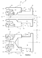
- the second component 24 has an annular sub-assembly 109 and four pins 111, 113a, 113b, 113c.
- Annular sub-assembly 109 has a generally annular body 108, outer and inner ring structures 138, 147 and resilient members 117a, 117b that are assembled to annular body 108, as will be further described below.
- the annular sub-assembly 109 has an outer cylindrical surface 114 having an axis A.
- the generally annular body 108 has a main body portion 115, a first annular protrusion 110 and a second annular protrusion 112.
- the main body portion 115 has an inner cylindrical surface 116 and a generally annular surface 120.
- first annular protrusion 110 Protruding from the main body portion 115 is the first annular protrusion 110 which has a generally flat annular 'L'-shaped surface 118 and generally flat annular surface 196. Also protruding from the main body portion 115 is the second annular protrusion 112, which has a generally annular 'L'-shaped surface 119, generally flat annular surface 198 and generally cylindrical surface 143.
- the annular sub-assembly 109 has four holes in the generally flat annular surface 120. As shown in figure 5 , one of the holes 121 is a through hole with an axis G and a second hole 123a is a blind hole with an axis K. The two further holes (not shown) are blind holes, have axes M and N and are the same shape as hole 123a.
- the outer ring structure 138 has a generally 'L'-shaped cross-section, a flat annular surface 140, an inner cylindrical surface 142 and a surface 146.
- the inner ring structure 147 has a generally 'L'-shaped cross-section, a flat annular surface 148, an inner cylindrical surface 150, and a surface 154.
- the outer resilient member 117a has an inner surface 190 and an outer surface 191.
- the inner resilient member 117b has an inner surface 192 and an outer surface 193.
- the first pin 111 of the second component 24 has an axis G and is shown in figures 2 , 5 , 6 and 7 .
- the first pin 111 has a stepped cylindrical body 82 having a first outer surface 84, a second outer surface 86, a third outer surface 88, a first shoulder 90 between the first surface 84 and the second surface 86 and a second shoulder 92 between the second surface 86 and the third surface 88.
- the first pin 111 has a flat annular face 89 adjacent to the third outer surface 88.
- the flat annular face 89 has a cross sectional area of ( ⁇ x (F/2) 2 ) - ( ⁇ x (Q/2) 2 ).
- the first pin 111 has a fluid passage 94 and opening 95, both the passage 94 and opening 95 having a diameter Q.
- the opening 95 has a cross-sectional area of ⁇ x (Q/2) 2 .
- the second pin 113a of the second component 24 has an axis K and is shown in figures 2 , 5 and 8 .
- the second pin 113a has a second stepped cylindrical body 96 having a first outer surface 98, a second outer surface 100, a third outer surface 102, a first shoulder 104 between the first surface 98 and the second surface 100 and a second shoulder 106 between the second surface 100 and the third surface 102.
- the second component 24 has two further pins, namely third pin 113b and fourth pin 113c.
- the third and fourth pins 113b, 113c are the same shape as the second pin 113a and have axes M and N, respectively.
- the actuator 20 has a cap 155 (see figures 2 , 6 and 7 ) having a generally annular body 157 with an axis G.
- the cap 155 has a flange portion 156 having an inlet 158 with a through hole 159.
- the inlet 158 and through hole 159 have an axis O.
- the cap 155 has a protrusion 160 having a diameter P.
- the cap structure 155 has an outer cylindrical wall 162 and an annular manifold 164.
- the actuator 20 has a main bush 172 having an axis A, an outer surface 174 and an inner surface 176, as shown in figures 1 , 6 , 7 and 8 .
- the actuator 20 has a second bush 178 having an axis G, an outer surface 180 and an inner surface 182, as shown in figures 1 , 6 and 7 .
- the actuator 20 has a third bush 184 having an axis K, an outer surface 186 and an inner surface 188, as shown in figures 1 and 8 .
- the actuator 20 has two further bushes (not shown) that are the same shape as the third bush 184 and have axes M and N.
- the actuator 20 has a first helical spring 166 (see figure 8 ) having a first end 168, a second end 170 and an axis K.
- the actuator 20 has two further helical springs (not shown) that are the same shape as the first helical spring 166 and have axes M and N.
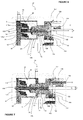
- the actuator 20 is assembled as follows:
- Resilient member 117a is mounted between the outer ring structure 138 and first annular protrusion 110 such that the inner surface 190 of resilient member 117a is in abutment with surface 146 of the outer ring structure 138 and the outer surface 191 of resilient member 117a is in abutment with surface 118 of the first annular protrusion 110 (as shown in figure 6 ).
- the outer ring structure 138 and resilient member 117a define an outer face seal.
- Resilient member 117b is similarly mounted between the inner ring structure 147 and second annular protrusion 112 such that the inner surface 192 of resilient member 117b is adhered to the surface 154 of the inner ring structure 147 and the outer surface 193 of resilient member 117b is in abutment with surface 119 of the second annular protrusion 112 (as shown in figure 6 ).
- the inner ring structure 147 and resilient member 117b define an inner face seal.
- An annular manifold 145 is formed between surface 142 of the outer ring structure 138 and inner surface 143 of the second annular protrusion 112.
- the first component 22 and bushings 172, 178 and 184 are assembled together as described below.
- Main bushing 172 is inserted into the recess 58 such that the inner surface 176 of the main bushing 172 is in interference fit engagement with the cylindrical inner wall 64 of the recess 58 thereby making the bush 172 axially and rotationally fast with respect to the first component 22.
- the second bushing 178 is inserted into the hole 68 such that the outer surface 180 of the second bushing 178 is in interference fit engagement with the walls of the hole 68 having a diameter H thereby making the bush 178 axially and radially fast with respect to the first component 22.
- the third bushing 184 is inserted into the hole 76a such that the outer surface 186 of the third bushing 184 is in interference fit engagement with the walls of the hole 76a having a diameter L.
- Two additional bushings are inserted into holes 76b, 76c in a similar way thereby making the third bush 184 and two additional bushes (not shown) axially and radially fast with respect to the first component 22.
- the annular sub-assembly 109 is inserted into the recess 58.
- Surface 116 of the main body portion 115 of the generally annular body 108 is in sliding engagement with the outer surface 174 of the main bushing 172.
- Cylindrical surface 150 of the inner ring structure 147 is adjacent but spaced from the cylindrical inner wall 64 of the recess 58 and cylindrical outer wall 62 of the recess 58 is adjacent but spaced from surface 114 of the annular sub-assembly 109.
- Generally flat annular surface 120 of the generally annular body 108 abuts the generally flat annular surface 66 of the recess 58.
- a helical spring 166 is inserted into the hole 76a such that a second end 170 of the spring 166 abuts step 78 within the hole 76a and an outer surface 171 of the spring 166 is a loose fit with the walls of the hole 76a having a diameter J.
- the second pin 113a is inserted through the hole 76a in the first component 22 and is fitted into the blind hole 123a in the generally flat annular surface 120 of the generally annular body 108.
- a first shoulder 104 of the pin 113a abuts the generally flat annular surface 120.
- the second outer cylindrical surface 100 of the pin 113a is in sliding engagement with the inner surface 188 of the third bushing 184.
- the third outer cylindrical surface 102 of the pin 113a is in clearance fit with the walls of the hole 76a having a diameter J.
- the shoulder 106 of the pin 113a abuts a first end 168 of the helical spring 166, which is under compression since the free length of the spring 166 prior to assembly was such that for end 170 to be press fitted with step 78 compression of the spring 166 is required.
- Two additional helical springs (not shown) are inserted into holes 76b, 76c as described for the first helical spring 166 above.
- the third and fourth pins 113b, 113c are inserted into holes 76b, 76c, respectively, as described for the second pin 113a above.
- the first pin 111 is inserted through the hole 68 in the first component 22 and into the through-hole 121 in the generally flat annular surface 120 of the generally annular body 108.
- the first shoulder 90 of the pin 111 abuts the generally flat annular surface 120.
- the second outer cylindrical surface 86 of the pin 111 is in sliding engagement with the inner surface 182 of the second bushing 178.
- the third outer cylindrical surface 88 of the pin 111 is in sliding engagement with the walls of the hole 68 having a diameter F.
- the surface 88 and the walls of the hole 68 having a diameter F are in sealing contact, with a small gap between surface 88 and the walls of the hole 68 having a diameter F.
- the cap 155 is fitted to the actuator assembly 20.
- the outer wall 162 of the body 157 of the cap 155 is in interference engagement fit with the walls of the hole 68 having a diameter F.
- the flange 156 of the cap 155 acts as an assembly aid and fits into the walls of the hole 68 having a diameter R but cannot pass beyond the shoulder 71 of the hole 68 and so cannot be pushed too far into the hole 68.
- the helical spring 166 bias the pin 111 such that the manifold 164 of the cap 155 is adjacent to the annular face 89 of the pin 111 and the protrusion 160 of the cap 155 is in a loose fit with the walls of the fluid passage 94.
- the actuator assembly 20 is fitted to the wheel spindle 40.
- Inner surface 54 of the first component 22 is in interference fit engagement with the outer surface 44 of the first portion 42 of the wheel spindle 40 and shoulder 56 and inner surface 55 of the first component 22 surround shoulder 50 and outer surface 48 of the wheel spindle 40. Accordingly, the actuator assembly 20 is held rotatably and axially fast relative to the wheel spindle 40.
- a wheel hub 30 is mounted on bearings (not shown) which in turn are mounted on the wheel spindle 40 assembly such that generally flat annular surface 34 of the wheel hub is adjacent to but spaced from the annular surface 140 of the outer ring structure 138, annular surface 148 of the inner ring structure 147 and generally flat annular surface 61 of the first component 22.
- the wheel hub 30 has a diameter U and the outer walls 31 are adjacent to the cylindrical outer wall 62 of the recess 58 in the first component.
- the inlet 38 of the fluid passage of the wheel hub 30 is radially aligned with the manifold 145 of the actuator 20.
- the wheel hub 30 has a fluid passage 36 which connects inlet 38 with a tyre 15 on a wheel (not shown).
- Fluid passage 12 connects pressurised air supply 10 to the inlet 158 of the through hole 159.
- valve 8 When it is desired to add air to the tyre 15, valve 8 is opened thereby allowing air to pass out of pressurised air supply 10 into fluid passage 12. Air then flows through the through-hole 159 in the inlet 158 of cap 155.
- the outer surface 88 of the pin 111 is in sufficient sealing contact with the walls of hole 68 having a diameter F that a volume of air is collected within a cavity 163 between the face 89 of the pin 111 and the manifold 164 of the cap 155.
- air can pass from the cavity 163 through the fluid passage 94 into the manifold 145, and from the manifold 145 to the rotatable fluid passage 36.
- the increased pressure of air in the rotatable fluid passage 36 causes the schrader valve 18 to open and allows air to pass into the tyre 15.
- the valve 8 When the pressure of air in the tyre 15 is sufficient, the valve 8 is closed to prevent further air entering the actuator 20 from the pressurised air supply 10. Air in the actuator 20 naturally decays from the system by passing through small gaps between the annular body 108 and the walls 62 and 64 of the recess 58 in the first component 22 and between the surface 88 of the pin 111 and the walls of the hole 68 having a diameter F. The decreased pressure of air in the rotatable fluid passage 36 causes the schrader valve 18 to close, preventing the loss of air from the tyre 15.
- the force acting on the face 89 of the pin 111 is less than that of the springs 166 acting on the pins 113a, 113b, 113c and so the pin 111 is moved to the light when viewing figures 1 and 6 to the first position in which surface 140 of outer ring structure 138 and surface 148 of the inner ring structure 147 move away from the rotatable surface 34 of the wheel hub 30 and surface 120 of the annular body 108 moves towards surface 66 of the recess 58 until the actuator has adopted the first position (as shown in figures 1 and 6 and as described above).
- the pressurised air supply 10 can be used to both activate the actuator 20 and supply air to a tyre 15 of a vehicle and the rotatable surface 34 of the wheel hub 30 is only brought into sealing contact with the sealing surfaces 140, 148 of the actuator 20 when required, thereby preventing unnecessary wear of the sealing surfaces 140, 148 and consequential power loss.
- Resilient members 117a, 117b provide better sealing engagement between the rotatable surface 34 of the wheel hub 30 and sealing surfaces 140, 148 of the outer and inner ring structures 138, 147.
- Resilient members 117a, 117b provide the actuator 20 with axial resilience.
- the resilient members 117a, 117b allow the sealing surfaces 140, 148 to contact the rotatable surface 34 of the wheel hub 30 just prior to the fluid passage 94 being brought into fluid communication with the cavity 163 by the pin 111 moving away from the protrusion 160 of the cap 155.
- the resilience of the resilient members 117a, 117b allows the pin 111 to move further away from the protrusion 160 to open the fluid passage 94.
- a protrusion of the first component engages the second component to isolate the first fluid passage from the second fluid passage.
- the protrusion 160 of the cap 155 of the first component 22 is positioned within the walls of the fluid passage 94 thereby isolating the first fluid passage 159 from the second fluid passage 94.
- a protrusion of the second component engages the first component to isolate the first fluid passage from the second fluid passage.
- the pin 111 may include a protrusion on its face 89 that engages an aperture in the cap 155 of the first component 22 to isolate the first fluid passage 159 from the second fluid passage 94.
- the cross sectional area of the face 89 of the pin 111 of the second component 24 is greater than the cross sectional area of the second fluid passage 94 because the face 89 has a cross sectional area of ( ⁇ x (F/2) 2 ) - ( ⁇ x (Q/2) 2 ), where ( ⁇ x (Q/2) 2 ) is the cross sectional area of the second fluid passage 94.
- the cross sectional area of the face 89 may be increased relative to the cross sectional area of the second fluid passage 94 in order to lower the pressure of air required to move the second component 24 relative to the first component 22.
- the cross sectional area of the face 89 may be decreased relative to the cross sectional area of the second fluid passage 94, resulting in an increase in the pressure of air required to move the second component 24 relative to the first component 22.
- the actuator 20 has one bearing 172 having an axis A coincident with the axis of rotation of the rotatable wheel hub 30 and four further bearings having axes G, K, M and N that are offset relative to the axis of rotation A of the rotatable wheel hub 30.
- the purpose of the bearings is to enable axial movement of the second component 24 relative to the first component 22.
- the actuator may not have any bearings, alternatively in other embodiments the actuator may include any number of bearings having axes coincident with the axis of rotation of the rotatable wheel hub 30 and/or any number of bearings having axes that are offset relative to the axis of rotation of the rotatable wheel hub 30 without departing from the scope of the present invention.
- any type of bearing or bushing that enables movement of the second component 24 relative to the first component 22 may be used.
- the resilient members 117a, 117b may be made from any suitable resilient material, for example any elastomeric material.
- the resilient members 117a, 117b may be O-rings.
- the sealing surfaces 140, 148 are independently mounted to the annular body 108 of the second component 24. In alternative embodiments of the present invention, the sealing surfaces 140, 148 may be connected. The sealing surfaces 140, 148 may, for example, be part of a single ring structure.
- sealing surfaces 140, 148 are generally flat. In alternative embodiments the sealing surfaces 140, 148 may be conical.
- resilient member 117a is mounted between the outer ring structure and the first annular protrusion 110.
- inner surface 190 of resilient member 117a may be adhered to surface 146 of the outer ring structure 138 and/or the outer surface 191 of resilient member 117a may be adhered to surface 118 of the first annular protrusion 110.
- the resilient member 117b is mounted between the inner ring structure 147 and the second annular protrusion 112.
- the inner surface 192 of resilient member 117b may be adhered to the surface 154 of the inner ring structure 147 and/or the outer surface 193 of the resilient member 117b may be adhered to surface 119 of the second annular protrusion 112.
- outer and inner ring structures 138, 147 may be separately bonded to annular body 108.
- the annular sub-assembly 109 may be constructed by taking generally annular body 108 and adhering outer ring structure 138 to the first annular protrusion 110 of the main body portion 115 using a rubber adhesive and adhering inner ring structure 147 to the second annular protrusion 112 of the main body portion 115 using a rubber adhesive.
- the rubber adhesive may be allowed to cure such that resilient members in the shape of resilient members 117a and 117b are formed.
- a resilient member that is in the shape of resilient member 117a is formed between the outer ring structure 138 and first annular protrusion 110, such that an inner surface of the resilient member is adhered to surface 146 of the outer ring structure 138 and an outer surface of the resilient member is adhered to surface 118 of the first annular protrusion 110.
- a resilient member that is in the shape of resilient member 117b is formed between the inner ring structure 147 and second annular protrusion 112 such that an inner surface of the resilient member is adhered to the surface 154 of the inner ring structure 147 and an outer surface of the resilient member is adhered to surface 119 of the second annular protrusion 112.
- the second component 24 has a single pin 111 having a fluid passage 94 and an opening 95. It will be appreciated that the second component may have a plurality of pins, each having fluid passage and an opening.
- the second component 24 has three pins 113a, 113b, 113c.
- the pins 113a, 113b, 113c prevent rotation of the first component 22 relative to the second component 24. It will be appreciated that rotation of the first component 22 relative to the second component 24 may be prevented by any suitable means or alternatively any number of pins may be used.
- each of the three pins 113a, 113b, 113c is associated with a spring 166.
- the purpose of the springs 166 is to bias the first component 22 away from the wheel hub 30. It will be appreciated that the first component 22 may be biased away from the wheel hub 30 by any suitable means. Alternatively, any number of springs that may, or may not, be associated with pins may be used to bias the first component 22 away from the wheel hub 30.
- the present invention allows the tyre of a vehicle to be inflated while the vehicle is moving and when the vehicle is stationary.
- the valve 8 may be opened in order to actuate the actuator 20 manually by an operator, either in response to a monitored tyre pressure reading or independently of the tyre pressure, for example when changing the terrain a vehicle is travelling on. Alternatively, the valve 8 may be opened automatically in response to a monitored tyre pressure reaching a threshold value.
Priority Applications (4)
| Application Number | Priority Date | Filing Date | Title |
|---|---|---|---|
| EP15162026.7A EP3075574B1 (fr) | 2015-03-31 | 2015-03-31 | Actionneur |
| CN201610187441.6A CN106004264B (zh) | 2015-03-31 | 2016-03-29 | 致动器 |
| US15/085,550 US10137746B2 (en) | 2015-03-31 | 2016-03-30 | Actuator |
| BR102016007221-2A BR102016007221B1 (pt) | 2015-03-31 | 2016-03-31 | Atuador para um sistema de insuflação de pneu e sistema e método para alterar uma pressão em um pneu |
Applications Claiming Priority (1)
| Application Number | Priority Date | Filing Date | Title |
|---|---|---|---|
| EP15162026.7A EP3075574B1 (fr) | 2015-03-31 | 2015-03-31 | Actionneur |
Publications (2)
| Publication Number | Publication Date |
|---|---|
| EP3075574A1 true EP3075574A1 (fr) | 2016-10-05 |
| EP3075574B1 EP3075574B1 (fr) | 2017-11-08 |
Family
ID=52874954
Family Applications (1)
| Application Number | Title | Priority Date | Filing Date |
|---|---|---|---|
| EP15162026.7A Active EP3075574B1 (fr) | 2015-03-31 | 2015-03-31 | Actionneur |
Country Status (4)
| Country | Link |
|---|---|
| US (1) | US10137746B2 (fr) |
| EP (1) | EP3075574B1 (fr) |
| CN (1) | CN106004264B (fr) |
| BR (1) | BR102016007221B1 (fr) |
Families Citing this family (4)
| Publication number | Priority date | Publication date | Assignee | Title |
|---|---|---|---|---|
| US20190263200A1 (en) * | 2018-02-26 | 2019-08-29 | Benjamin J. Krempel | Pumping Mechanism Insert |
| US11571935B2 (en) | 2019-10-04 | 2023-02-07 | Louis J. Finkle | Tire inflator |
| TWI791337B (zh) * | 2021-11-25 | 2023-02-01 | 吳樹木 | 適用多種氣嘴之打氣筒夾頭 |
| US11789474B2 (en) | 2021-12-06 | 2023-10-17 | Motool Llc | Pressure gauge with automatic bleed valve |
Citations (5)
| Publication number | Priority date | Publication date | Assignee | Title |
|---|---|---|---|---|
| US4434833A (en) | 1982-04-21 | 1984-03-06 | Eaton Corporation | Axle wheel end assembly |
| US4705090A (en) | 1986-01-17 | 1987-11-10 | Tire Inflation Systems Corp. | Apparatus for controlling air pressure in vehicle tires |
| US4892128A (en) | 1987-08-28 | 1990-01-09 | Tire Inflation Systems Corp. | Vehicle wheel seal assembly |
| EP1147925A2 (fr) * | 2000-04-19 | 2001-10-24 | Firma Carl Freudenberg | Dispositif d'étanchéité |
| WO2014135164A1 (fr) * | 2013-03-05 | 2014-09-12 | Schaeffler Technologies Gmbh & Co. Kg | Passage tournant et installation de régulation de la pression d'un pneumatique pourvue d'un passage tournant |
Family Cites Families (20)
| Publication number | Priority date | Publication date | Assignee | Title |
|---|---|---|---|---|
| US2090089A (en) * | 1935-08-27 | 1937-08-17 | Wiegand Carl | Means for inflating rotating tires |
| US4431043A (en) | 1981-07-31 | 1984-02-14 | Am General Corporation | Automatic tire inflation system |
| US4418737A (en) | 1981-07-31 | 1983-12-06 | Am General Corporation | Automatic tire inflation system |
| US4470506A (en) | 1981-10-16 | 1984-09-11 | Am General Corporation | Automatic tire inflation system retrofitting kit |
| US4440451A (en) | 1981-10-16 | 1984-04-03 | Am General Corp. | Vehicle hub with bearing removable feature |
| US4582107A (en) | 1984-07-26 | 1986-04-15 | The United States Of America As Represented By The Secretary Of The Army | Vehicle tire inflation-deflation mechanism |
| US5174839A (en) | 1991-07-05 | 1992-12-29 | Eaton Corporation | Drive axle sleeve and seal assembly |
| US5253688A (en) | 1991-09-12 | 1993-10-19 | Tigges & Winckel Bonumwerke | Tire pressure control system |
| US5452753A (en) * | 1993-04-22 | 1995-09-26 | Hughes Aircraft Company | Vehicle tire management system including wheel with self-contained tire inflation/deflation apparatus |
| DE60206430T2 (de) | 2001-02-22 | 2006-06-29 | ArvinMeritor Technology, LLC, Troy | Fahrzeugrad mit Endanordnung |
| DE102005018584A1 (de) | 2005-04-21 | 2006-10-26 | Deere & Company, Moline | Vorrichtung, insbesondere Drehdurchführung |
| JP2009160962A (ja) * | 2007-12-28 | 2009-07-23 | Jtekt Corp | 転がり軸受装置 |
| US7690412B1 (en) | 2008-11-04 | 2010-04-06 | Arvinmeritor Technology, Llc | Drive axle with air passage for tire inflation system |
| US7931061B2 (en) | 2008-12-15 | 2011-04-26 | Arvinmeritor Technology, Llc | Tire inflation system with integrated wheel seal |
| CN103282655B (zh) * | 2010-06-21 | 2016-08-24 | 伊夸莱尔系统公司 | 用于轮胎充气系统的具有中心阀的旋转空气连接件 |
| US8616254B2 (en) | 2011-09-23 | 2013-12-31 | Arvinmeritor Technology, Llc | Wheel hub with air passage for tire inflation system |
| US9126460B2 (en) | 2012-03-02 | 2015-09-08 | Dana Heavy Vehicle Systems Group, Llc | Tire inflation system having a sleeve shaped air passage |
| US9452644B2 (en) | 2013-09-18 | 2016-09-27 | Arvinmeritor Technology, Llc | Tire inflation system with a passage for routing pressurized gas |
| CN104044414A (zh) * | 2014-05-26 | 2014-09-17 | 重庆滟昭汽车科技有限公司 | 一种旋转密封装置 |
| CN204196602U (zh) * | 2014-10-31 | 2015-03-11 | 东风商用车有限公司 | 一种中央充放气的气路结构 |
-
2015
- 2015-03-31 EP EP15162026.7A patent/EP3075574B1/fr active Active
-
2016
- 2016-03-29 CN CN201610187441.6A patent/CN106004264B/zh active Active
- 2016-03-30 US US15/085,550 patent/US10137746B2/en active Active
- 2016-03-31 BR BR102016007221-2A patent/BR102016007221B1/pt active IP Right Grant
Patent Citations (5)
| Publication number | Priority date | Publication date | Assignee | Title |
|---|---|---|---|---|
| US4434833A (en) | 1982-04-21 | 1984-03-06 | Eaton Corporation | Axle wheel end assembly |
| US4705090A (en) | 1986-01-17 | 1987-11-10 | Tire Inflation Systems Corp. | Apparatus for controlling air pressure in vehicle tires |
| US4892128A (en) | 1987-08-28 | 1990-01-09 | Tire Inflation Systems Corp. | Vehicle wheel seal assembly |
| EP1147925A2 (fr) * | 2000-04-19 | 2001-10-24 | Firma Carl Freudenberg | Dispositif d'étanchéité |
| WO2014135164A1 (fr) * | 2013-03-05 | 2014-09-12 | Schaeffler Technologies Gmbh & Co. Kg | Passage tournant et installation de régulation de la pression d'un pneumatique pourvue d'un passage tournant |
Also Published As
| Publication number | Publication date |
|---|---|
| CN106004264A (zh) | 2016-10-12 |
| BR102016007221A2 (pt) | 2018-03-20 |
| BR102016007221B1 (pt) | 2021-09-08 |
| CN106004264B (zh) | 2018-04-27 |
| EP3075574B1 (fr) | 2017-11-08 |
| US10137746B2 (en) | 2018-11-27 |
| US20160288599A1 (en) | 2016-10-06 |
Similar Documents
| Publication | Publication Date | Title |
|---|---|---|
| US10137746B2 (en) | Actuator | |
| US20100065177A1 (en) | Wheel axle and drive or universal shaft for vehicles with a central tyre pressure supply | |
| US9409449B2 (en) | Spindle assembly for a tire inflation system | |
| FI66064B (fi) | Anordning foer att tillsluta en ringformad oeppning mellan en inre del och en denna omgivande yttre del | |
| US20090272929A1 (en) | Axial drag valve with internal hub actuator | |
| KR101429577B1 (ko) | 밸런스 포핏식 전자 밸브 | |
| JP5456485B2 (ja) | スライド・バルブ | |
| JP2006002941A (ja) | フルートを備えたボア中に空気の流通路を有するローラベアリング | |
| KR20190126284A (ko) | 방사형 피스톤을 포함하는 압축기 어셈블리 | |
| EP3439895B1 (fr) | Dispositif de raccordement pour un essieu d'un véhicule | |
| DE102009057158A1 (de) | Drehdurchführung | |
| DE102004021161B4 (de) | Drehdurchführung einer Reifendruckregelung | |
| DE102012217040A1 (de) | Luftführungsanordnung zur Reifendruck-Regulierung | |
| EP3535143B1 (fr) | Ensemble joint rotatif pour un système de gonflage de pneumatique | |
| US11571935B2 (en) | Tire inflator | |
| CN108561654B (zh) | 一种旋转接头 | |
| AU2011200796B2 (en) | Drill string valve actuator with inflatable seals | |
| DE112016004794T5 (de) | Radanschlussanordnung für ein reifendruckregelsystem und damit hergestelltes reifendruckregelsystem | |
| US11459889B2 (en) | Hydraulic arrangement for a steered wheel of a vehicle | |
| EP3416834B1 (fr) | Ensemble de traversée rotative pour un système de gonflage de pneu | |
| DE102007054887A1 (de) | Dichtungsvorrichtung für ein Kraftfahrzeugrad | |
| CN111561580B (zh) | 轴流式控制阀 | |
| BR102014011738A2 (pt) | um sistema | |
| CN212564531U (zh) | 一种双阀芯电控三通阀门 | |
| CN102678643A (zh) | 手动换向阀及其密封结构 |
Legal Events
| Date | Code | Title | Description |
|---|---|---|---|
| PUAI | Public reference made under article 153(3) epc to a published international application that has entered the european phase |
Free format text: ORIGINAL CODE: 0009012 |
|
| AK | Designated contracting states |
Kind code of ref document: A1 Designated state(s): AL AT BE BG CH CY CZ DE DK EE ES FI FR GB GR HR HU IE IS IT LI LT LU LV MC MK MT NL NO PL PT RO RS SE SI SK SM TR |
|
| AX | Request for extension of the european patent |
Extension state: BA ME |
|
| 17P | Request for examination filed |
Effective date: 20170403 |
|
| RBV | Designated contracting states (corrected) |
Designated state(s): AL AT BE BG CH CY CZ DE DK EE ES FI FR GB GR HR HU IE IS IT LI LT LU LV MC MK MT NL NO PL PT RO RS SE SI SK SM TR |
|
| GRAP | Despatch of communication of intention to grant a patent |
Free format text: ORIGINAL CODE: EPIDOSNIGR1 |
|
| INTG | Intention to grant announced |
Effective date: 20170601 |
|
| RIN1 | Information on inventor provided before grant (corrected) |
Inventor name: BIONAZ, DAVIDE Inventor name: BASSI, MARCO Inventor name: KEANE, JAMES Inventor name: TIZIANI, EUGENIO |
|
| GRAS | Grant fee paid |
Free format text: ORIGINAL CODE: EPIDOSNIGR3 |
|
| GRAA | (expected) grant |
Free format text: ORIGINAL CODE: 0009210 |
|
| AK | Designated contracting states |
Kind code of ref document: B1 Designated state(s): AL AT BE BG CH CY CZ DE DK EE ES FI FR GB GR HR HU IE IS IT LI LT LU LV MC MK MT NL NO PL PT RO RS SE SI SK SM TR |
|
| REG | Reference to a national code |
Ref country code: GB Ref legal event code: FG4D |
|
| REG | Reference to a national code |
Ref country code: CH Ref legal event code: EP Ref country code: AT Ref legal event code: REF Ref document number: 943781 Country of ref document: AT Kind code of ref document: T Effective date: 20171115 |
|
| REG | Reference to a national code |
Ref country code: IE Ref legal event code: FG4D |
|
| REG | Reference to a national code |
Ref country code: DE Ref legal event code: R096 Ref document number: 602015005790 Country of ref document: DE |
|
| REG | Reference to a national code |
Ref country code: NL Ref legal event code: FP |
|
| REG | Reference to a national code |
Ref country code: SE Ref legal event code: TRGR |
|
| REG | Reference to a national code |
Ref country code: LT Ref legal event code: MG4D Ref country code: FR Ref legal event code: PLFP Year of fee payment: 4 |
|
| REG | Reference to a national code |
Ref country code: AT Ref legal event code: MK05 Ref document number: 943781 Country of ref document: AT Kind code of ref document: T Effective date: 20171108 |
|
| PG25 | Lapsed in a contracting state [announced via postgrant information from national office to epo] |
Ref country code: ES Free format text: LAPSE BECAUSE OF FAILURE TO SUBMIT A TRANSLATION OF THE DESCRIPTION OR TO PAY THE FEE WITHIN THE PRESCRIBED TIME-LIMIT Effective date: 20171108 Ref country code: NO Free format text: LAPSE BECAUSE OF FAILURE TO SUBMIT A TRANSLATION OF THE DESCRIPTION OR TO PAY THE FEE WITHIN THE PRESCRIBED TIME-LIMIT Effective date: 20180208 Ref country code: FI Free format text: LAPSE BECAUSE OF FAILURE TO SUBMIT A TRANSLATION OF THE DESCRIPTION OR TO PAY THE FEE WITHIN THE PRESCRIBED TIME-LIMIT Effective date: 20171108 Ref country code: LT Free format text: LAPSE BECAUSE OF FAILURE TO SUBMIT A TRANSLATION OF THE DESCRIPTION OR TO PAY THE FEE WITHIN THE PRESCRIBED TIME-LIMIT Effective date: 20171108 |
|
| PG25 | Lapsed in a contracting state [announced via postgrant information from national office to epo] |
Ref country code: HR Free format text: LAPSE BECAUSE OF FAILURE TO SUBMIT A TRANSLATION OF THE DESCRIPTION OR TO PAY THE FEE WITHIN THE PRESCRIBED TIME-LIMIT Effective date: 20171108 Ref country code: AT Free format text: LAPSE BECAUSE OF FAILURE TO SUBMIT A TRANSLATION OF THE DESCRIPTION OR TO PAY THE FEE WITHIN THE PRESCRIBED TIME-LIMIT Effective date: 20171108 Ref country code: LV Free format text: LAPSE BECAUSE OF FAILURE TO SUBMIT A TRANSLATION OF THE DESCRIPTION OR TO PAY THE FEE WITHIN THE PRESCRIBED TIME-LIMIT Effective date: 20171108 Ref country code: IS Free format text: LAPSE BECAUSE OF FAILURE TO SUBMIT A TRANSLATION OF THE DESCRIPTION OR TO PAY THE FEE WITHIN THE PRESCRIBED TIME-LIMIT Effective date: 20180308 Ref country code: GR Free format text: LAPSE BECAUSE OF FAILURE TO SUBMIT A TRANSLATION OF THE DESCRIPTION OR TO PAY THE FEE WITHIN THE PRESCRIBED TIME-LIMIT Effective date: 20180209 Ref country code: BG Free format text: LAPSE BECAUSE OF FAILURE TO SUBMIT A TRANSLATION OF THE DESCRIPTION OR TO PAY THE FEE WITHIN THE PRESCRIBED TIME-LIMIT Effective date: 20180208 Ref country code: RS Free format text: LAPSE BECAUSE OF FAILURE TO SUBMIT A TRANSLATION OF THE DESCRIPTION OR TO PAY THE FEE WITHIN THE PRESCRIBED TIME-LIMIT Effective date: 20171108 |
|
| PG25 | Lapsed in a contracting state [announced via postgrant information from national office to epo] |
Ref country code: CY Free format text: LAPSE BECAUSE OF FAILURE TO SUBMIT A TRANSLATION OF THE DESCRIPTION OR TO PAY THE FEE WITHIN THE PRESCRIBED TIME-LIMIT Effective date: 20171108 Ref country code: EE Free format text: LAPSE BECAUSE OF FAILURE TO SUBMIT A TRANSLATION OF THE DESCRIPTION OR TO PAY THE FEE WITHIN THE PRESCRIBED TIME-LIMIT Effective date: 20171108 Ref country code: DK Free format text: LAPSE BECAUSE OF FAILURE TO SUBMIT A TRANSLATION OF THE DESCRIPTION OR TO PAY THE FEE WITHIN THE PRESCRIBED TIME-LIMIT Effective date: 20171108 Ref country code: CZ Free format text: LAPSE BECAUSE OF FAILURE TO SUBMIT A TRANSLATION OF THE DESCRIPTION OR TO PAY THE FEE WITHIN THE PRESCRIBED TIME-LIMIT Effective date: 20171108 Ref country code: SK Free format text: LAPSE BECAUSE OF FAILURE TO SUBMIT A TRANSLATION OF THE DESCRIPTION OR TO PAY THE FEE WITHIN THE PRESCRIBED TIME-LIMIT Effective date: 20171108 |
|
| REG | Reference to a national code |
Ref country code: DE Ref legal event code: R097 Ref document number: 602015005790 Country of ref document: DE |
|
| PG25 | Lapsed in a contracting state [announced via postgrant information from national office to epo] |
Ref country code: SM Free format text: LAPSE BECAUSE OF FAILURE TO SUBMIT A TRANSLATION OF THE DESCRIPTION OR TO PAY THE FEE WITHIN THE PRESCRIBED TIME-LIMIT Effective date: 20171108 Ref country code: IT Free format text: LAPSE BECAUSE OF FAILURE TO SUBMIT A TRANSLATION OF THE DESCRIPTION OR TO PAY THE FEE WITHIN THE PRESCRIBED TIME-LIMIT Effective date: 20171108 Ref country code: RO Free format text: LAPSE BECAUSE OF FAILURE TO SUBMIT A TRANSLATION OF THE DESCRIPTION OR TO PAY THE FEE WITHIN THE PRESCRIBED TIME-LIMIT Effective date: 20171108 Ref country code: PL Free format text: LAPSE BECAUSE OF FAILURE TO SUBMIT A TRANSLATION OF THE DESCRIPTION OR TO PAY THE FEE WITHIN THE PRESCRIBED TIME-LIMIT Effective date: 20171108 |
|
| PLBE | No opposition filed within time limit |
Free format text: ORIGINAL CODE: 0009261 |
|
| STAA | Information on the status of an ep patent application or granted ep patent |
Free format text: STATUS: NO OPPOSITION FILED WITHIN TIME LIMIT |
|
| 26N | No opposition filed |
Effective date: 20180809 |
|
| REG | Reference to a national code |
Ref country code: CH Ref legal event code: PL |
|
| PG25 | Lapsed in a contracting state [announced via postgrant information from national office to epo] |
Ref country code: MC Free format text: LAPSE BECAUSE OF FAILURE TO SUBMIT A TRANSLATION OF THE DESCRIPTION OR TO PAY THE FEE WITHIN THE PRESCRIBED TIME-LIMIT Effective date: 20171108 Ref country code: SI Free format text: LAPSE BECAUSE OF FAILURE TO SUBMIT A TRANSLATION OF THE DESCRIPTION OR TO PAY THE FEE WITHIN THE PRESCRIBED TIME-LIMIT Effective date: 20171108 |
|
| REG | Reference to a national code |
Ref country code: BE Ref legal event code: MM Effective date: 20180331 |
|
| REG | Reference to a national code |
Ref country code: IE Ref legal event code: MM4A |
|
| PG25 | Lapsed in a contracting state [announced via postgrant information from national office to epo] |
Ref country code: LU Free format text: LAPSE BECAUSE OF NON-PAYMENT OF DUE FEES Effective date: 20180331 |
|
| PG25 | Lapsed in a contracting state [announced via postgrant information from national office to epo] |
Ref country code: IE Free format text: LAPSE BECAUSE OF NON-PAYMENT OF DUE FEES Effective date: 20180331 |
|
| PG25 | Lapsed in a contracting state [announced via postgrant information from national office to epo] |
Ref country code: CH Free format text: LAPSE BECAUSE OF NON-PAYMENT OF DUE FEES Effective date: 20180331 Ref country code: BE Free format text: LAPSE BECAUSE OF NON-PAYMENT OF DUE FEES Effective date: 20180331 Ref country code: LI Free format text: LAPSE BECAUSE OF NON-PAYMENT OF DUE FEES Effective date: 20180331 |
|
| PG25 | Lapsed in a contracting state [announced via postgrant information from national office to epo] |
Ref country code: MT Free format text: LAPSE BECAUSE OF NON-PAYMENT OF DUE FEES Effective date: 20180331 |
|
| PG25 | Lapsed in a contracting state [announced via postgrant information from national office to epo] |
Ref country code: TR Free format text: LAPSE BECAUSE OF FAILURE TO SUBMIT A TRANSLATION OF THE DESCRIPTION OR TO PAY THE FEE WITHIN THE PRESCRIBED TIME-LIMIT Effective date: 20171108 |
|
| PG25 | Lapsed in a contracting state [announced via postgrant information from national office to epo] |
Ref country code: PT Free format text: LAPSE BECAUSE OF FAILURE TO SUBMIT A TRANSLATION OF THE DESCRIPTION OR TO PAY THE FEE WITHIN THE PRESCRIBED TIME-LIMIT Effective date: 20171108 |
|
| PG25 | Lapsed in a contracting state [announced via postgrant information from national office to epo] |
Ref country code: MK Free format text: LAPSE BECAUSE OF NON-PAYMENT OF DUE FEES Effective date: 20171108 Ref country code: HU Free format text: LAPSE BECAUSE OF FAILURE TO SUBMIT A TRANSLATION OF THE DESCRIPTION OR TO PAY THE FEE WITHIN THE PRESCRIBED TIME-LIMIT; INVALID AB INITIO Effective date: 20150331 |
|
| PG25 | Lapsed in a contracting state [announced via postgrant information from national office to epo] |
Ref country code: AL Free format text: LAPSE BECAUSE OF FAILURE TO SUBMIT A TRANSLATION OF THE DESCRIPTION OR TO PAY THE FEE WITHIN THE PRESCRIBED TIME-LIMIT Effective date: 20171108 |
|
| PGFP | Annual fee paid to national office [announced via postgrant information from national office to epo] |
Ref country code: FR Payment date: 20230327 Year of fee payment: 9 |
|
| PGFP | Annual fee paid to national office [announced via postgrant information from national office to epo] |
Ref country code: SE Payment date: 20230315 Year of fee payment: 9 |
|
| P01 | Opt-out of the competence of the unified patent court (upc) registered |
Effective date: 20230531 |
|
| PGFP | Annual fee paid to national office [announced via postgrant information from national office to epo] |
Ref country code: NL Payment date: 20240326 Year of fee payment: 10 |
|
| PGFP | Annual fee paid to national office [announced via postgrant information from national office to epo] |
Ref country code: DE Payment date: 20240327 Year of fee payment: 10 Ref country code: GB Payment date: 20240327 Year of fee payment: 10 |