EP3075353A1 - Instrument d'injection de lentille intraoculaire - Google Patents
Instrument d'injection de lentille intraoculaire Download PDFInfo
- Publication number
- EP3075353A1 EP3075353A1 EP16162653.6A EP16162653A EP3075353A1 EP 3075353 A1 EP3075353 A1 EP 3075353A1 EP 16162653 A EP16162653 A EP 16162653A EP 3075353 A1 EP3075353 A1 EP 3075353A1
- Authority
- EP
- European Patent Office
- Prior art keywords
- intraocular lens
- passage
- wall surface
- optical part
- support part
- Prior art date
- Legal status (The legal status is an assumption and is not a legal conclusion. Google has not performed a legal analysis and makes no representation as to the accuracy of the status listed.)
- Granted
Links
Images


Classifications
-
- A—HUMAN NECESSITIES
- A61—MEDICAL OR VETERINARY SCIENCE; HYGIENE
- A61F—FILTERS IMPLANTABLE INTO BLOOD VESSELS; PROSTHESES; DEVICES PROVIDING PATENCY TO, OR PREVENTING COLLAPSING OF, TUBULAR STRUCTURES OF THE BODY, e.g. STENTS; ORTHOPAEDIC, NURSING OR CONTRACEPTIVE DEVICES; FOMENTATION; TREATMENT OR PROTECTION OF EYES OR EARS; BANDAGES, DRESSINGS OR ABSORBENT PADS; FIRST-AID KITS
- A61F2/00—Filters implantable into blood vessels; Prostheses, i.e. artificial substitutes or replacements for parts of the body; Appliances for connecting them with the body; Devices providing patency to, or preventing collapsing of, tubular structures of the body, e.g. stents
- A61F2/02—Prostheses implantable into the body
- A61F2/14—Eye parts, e.g. lenses, corneal implants; Implanting instruments specially adapted therefor; Artificial eyes
- A61F2/16—Intraocular lenses
- A61F2/1662—Instruments for inserting intraocular lenses into the eye
- A61F2/167—Instruments for inserting intraocular lenses into the eye with pushable plungers
-
- A—HUMAN NECESSITIES
- A61—MEDICAL OR VETERINARY SCIENCE; HYGIENE
- A61F—FILTERS IMPLANTABLE INTO BLOOD VESSELS; PROSTHESES; DEVICES PROVIDING PATENCY TO, OR PREVENTING COLLAPSING OF, TUBULAR STRUCTURES OF THE BODY, e.g. STENTS; ORTHOPAEDIC, NURSING OR CONTRACEPTIVE DEVICES; FOMENTATION; TREATMENT OR PROTECTION OF EYES OR EARS; BANDAGES, DRESSINGS OR ABSORBENT PADS; FIRST-AID KITS
- A61F2250/00—Special features of prostheses classified in groups A61F2/00 - A61F2/26 or A61F2/82 or A61F9/00 or A61F11/00 or subgroups thereof
- A61F2250/0014—Special features of prostheses classified in groups A61F2/00 - A61F2/26 or A61F2/82 or A61F9/00 or A61F11/00 or subgroups thereof having different values of a given property or geometrical feature, e.g. mechanical property or material property, at different locations within the same prosthesis
- A61F2250/0021—Special features of prostheses classified in groups A61F2/00 - A61F2/26 or A61F2/82 or A61F9/00 or A61F11/00 or subgroups thereof having different values of a given property or geometrical feature, e.g. mechanical property or material property, at different locations within the same prosthesis differing in coefficient of friction
Definitions
- the present disclosure relates to an intraocular lens injection instrument for injecting an intraocular lens into a patient's eye.
- a method of injecting a foldable soft intraocular lens (IOL) into an eye as a substitute for a crystalline lens has been typically used.
- an IOL is injected anterior to the lens for the purpose of correcting a refractive power of an eye.
- an intraocular lens injection instrument called as an injector is used in some cases.
- an injector has been known with a configuration that an injection part formed with a cutout at its leading end includes a hollow portion having an inner diameter gradually decreasing toward the leading end, and an IOL is pushed out in the hollow portion and folded into a tiny piece so as to be injected outside from the leading end (for example, see Patent Document 1).
- Patent Document 1 JP-A-2010-082288
- a support part on a leading end side of the hollow portion is folded and stored to fold an IOL, but there is a case that the folded optical part fails to store the support part on the leading end side when the IOL is injected into an eye.
- the present disclosure has been made to address the above problem and has a purpose to provide an intraocular lens injection instrument configured to appropriately deform and inject an IOL.
- An intraocular lens injection instrument is an intraocular lens injection instrument for injecting an intraocular lens into an eye, the intraocular lens comprising an optical part of a disk-like shape and a first support part extending outwardly from an outer circumferential part of the optical part, characterized in that the intraocular lens injection instrument comprises: a passage having a passage area gradually decreasing toward a tip end of the intraocular lens injection instrument; inner wall surfaces formed on both sides in a direction orthogonal to an axial direction of the passage, the direction being parallel to a radial direction of the optical part when the intraocular lens is placed in the passage; a push member configured to push out the intraocular lens, the push member including a contact portion to be placed in contact with the intraocular lens; and a lens control mechanism to control an orientation of the intraocular lens in a circumferential direction of the optical part, the lens control mechanism being configured to direct movement of the contact portion of the push member toward one of the inner wall surfaces when or after the intra
- An intraocular lens injection instrument is an intraocular lens injection instrument for injecting an intraocular lens into an eye, the intraocular lens comprising an optical part of a disk-like shape and the first support part extending outwardly from an outer circumferential part of the optical part, characterized in that the intraocular lens injection instrument comprises: a passage having a sectional area gradually decreasing toward a tip end of the intraocular lens injection instrument; a first inner wall surface and a second inner wall surface formed on both sides in a direction orthogonal to an axial direction of the passage, the direction being parallel to a radial direction of the optical part when the intraocular lens is placed in the passage; and a push member configured to push out the intraocular lens, the intraocular lens is configured to be pushed toward the tip end by the push member when the optical part is in contact with the first inner wall surface and the second inner wall surface, and a first frictional force generated between the first inner wall surface and the optical part is differentiated from a second frictional force
- an IOL can be appropriately deformed and injected.
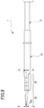
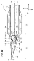
- the injector 1 of the present embodiment includes a cylinder body (hereinafter, referred as a "body") 10, a plunger 12 (a push member), and others.
- the body 10 is provided with an injection part 20, a setting part 22, and others.
- the injector 1 with this configuration is, for example, formed by injection molding using resin material (for example, polypropylene) or the like.
- the injector 1 may be formed by cutting or machining resin.
- the injector 1 may be a cartridge-type in which the injection part 20 is replaceable.
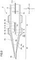
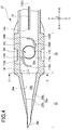
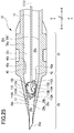
- the injection part 20 is formed in a cylindrical hollow shape. As shown in FIGs. 3 and 4 , the injection part 20 includes a passage 20b (a front-side passage).
- the passage 20b has a space made to be gradually narrow as coming close to a tip end 20a of the injection part 20 so that an intraocular lens (IOL) 100 is folded.
- IOL intraocular lens
- a passage area gradually decreases toward the tip end 20a.
- the passage area represents a sectional area of the passage 20b in a section orthogonal to a push-out direction (a leftward direction in FIGs. 3 and 4 ) of the IOL 100.
- the tip end 20a of the injection part 20 is formed with a cutout (bevel) for feeding the IOL 100 outside. While the IOL 100 is passing through the passage 20b, the IOL 100 is folded into a tiny piece along inner wall surfaces 20c (front-side inner wall surfaces) and then fed out from the cutout of the tip end 20a, so that the IOL 100 is injected into an eye.
- a cutout bevel
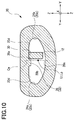
- the inner wall surfaces 20c are formed on both sides (both ends) in a direction orthogonal to a central axis Lt of the passage 20b, the direction being parallel to a radial direction of an optical part 110 when the IOL 100 is placed in the passage 20b (see FIG. 8 ).
- first inner wall surface 24a and the second inner wall surface 24b are formed (inclined) symmetrically with respect to the central axis Lt of the passage 20b.
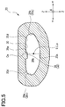
- a ceiling surface 20d (a first axial surface) and a bottom surface 20e (a second axial surface) are formed on both sides (both ends) in a direction orthogonal to the central axis Lt of the passage 20b, the direction being parallel to a central axis (an optical axis) L of the optical part 110 when the IOL 100 is placed in the passage 20b.
- the bottom surface 20e has the shape of an outward curve (a downward curve in FIG. 5 ) in the passage 20b to be in a recess-like shape.
- the bottom surface 20e is defined as a surface facing a first protrusion 32 (a protruding portion 36) mentioned below in the passage 20b, and thus the bottom surface 20e is recessed in a protruding direction of the first protrusion 32.
- axes X, Y, and Z which are orthogonally intersecting one another are assumed, and a direction indicated with the axis X is defined as a direction parallel to the push-out direction of the IOL 100 (a direction of the central axis Lt of the passage 20b and a passage 22a, a direction of a push-out axis Lp).
- the passage 20b is surrounded by the two inner wall surfaces 20c (the first inner wall surface 24a and the second inner wall surface 24b) formed on both sides in an axis Y direction, the ceiling surface 20d and the bottom surface 20e formed on both sides in an axis Z direction (see FIG. 5 ), and others.
- the central axis Lt of the passage 20b is coaxial with the push-out axis Lp.
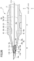
- the setting part 22 is located rearward (in a rightward direction in FIGs. 1 to 4 ) of the injection part 20 in the push-out direction of the plunger 12.
- a passage 22a (a rear-side passage) formed in the setting part 22, the IOL 100 which is ready to be pushed out by the plunger 12 is placed (see FIG. 4 ).
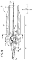
- the setting part 22 includes, as shown in FIGs. 3 and 4 , the passage 22a, a ceiling surface 22b, a bottom surface 22c, a guide portion 30, the first protrusion 32 (a first guide protrusion), a second protrusion 34 (a second guide protrusion), and others.
- the guide portion 30 is provided on the ceiling surface 22b to guide the push-out direction of the plunger 12.
- the first protrusion 32 and the second protrusion 34 are formed along the push-out direction of the plunger 12.
- the first protrusion 32 constitutes one wall surface (a lower side of the paper in FIG. 3 ) of the guide portion 30 and protrudes from the ceiling surface 20d and the ceiling surface 22b toward the bottom surface 20e and the bottom surface 22c (toward a front side of the paper in FIG. 3 ).
- the second protrusion 34 constitutes the other wall surface (an upper side of the paper in FIG. 3 ) of the guide portion 30 and protrudes from the ceiling surface 22b toward the bottom surface 22c (toward the front side of the paper in FIG. 3 ).
- the first protrusion 32 is provided with a protruding portion 36 (a lens control mechanism).
- the protruding portion 36 is provided in the first protrusion 32 close to the tip end 20a of the injection part 20.
- the protruding portion 36 is formed to protrude more inwardly toward an inside of the guide portion 30 than a guide face 32b facing the guide portion 30 in the first protrusion 32.
- the protruding portion 36 is formed in an inclined shape (a tapered shape) such that a guide face 36a facing the guide portion 30 gradually protrudes toward the inside of the guide portion 30 as coming close to the tip end 20a of the injection part 20.
- a protruding amount of the protruding portion 36 to the inside of the guide portion 30 is gradually increased as coming close to the tip end 20a of the injection part 20.
- the guide face 36a constitutes a face to guide the plunger 12 which will be mentioned later.
- the protruding portion 36 may be formed separately from the first protrusion 32.
- the protruding portion 36 protrudes from the ceiling surface 20d toward the bottom surface 20e in the passage 20b of the injection part 20.
- the protruding portion 36 protrudes also in the passage 22a of the setting part 22 from the ceiling surface 22b toward the bottom surface 22c.
- a part of the protruding portion 36 spreads over a central part Ce in a direction (an axis Y direction) orthogonal to the central axis Lt of the passage 20b and parallel to the radial direction of the optical part 110 when the IOL 100 is placed in the passage 20b.
- a front end portion 36b (an end portion on the tip end 20a side of the injection part 20) of the protruding portion 36 is formed to extend across the central part Ce from a point closer to the first inner wall surface 24a than the central part Ce to a point closer to the second inner wall surface 24b than the central part Ce in the axis Y direction (see FIG. 3 ).
- the protruding portion 36 may be formed not across the central part Ce but only formed on the first inner wall surface 24a side.
- the front end portion 34a of the second protrusion 34 close to the tip end 20a of the injection part 20 is formed more rearward than a front end portion 32a of the first protrusion 32 close to the tip end 20a in the push-out direction of the IOL 100.
- the ceiling surface 20d names such as "the ceiling surface 20d,” “the bottom surface 20e,” “the ceiling surface 22b,” and “the bottom surface 22c” are given as a matter of convenience, and those names do not strictly designate an upper and lower direction of the injector 1.
- the bottom surface 20e is not always located on a lower side of the IOL 100.
- the upper and lower sides of the injector 1 may be changed in each occasion of conveyance, filling a viscoelastic substance into the injector 1, injection of the IOL 100 into the eye, and others.
- the IOL 100 used in the present embodiment is a one-piece IOL integrally formed of the optical part 110 and a pair of support parts including a front-side support part 112A (a first support part) and a rear-side support part 112B (a second support part), which are made of soft material.
- the optical part 110 is formed in a disk-like shape.
- the front-side support part 112A and the rear-side support part 112B both extends outward from an outer circumferential part 110a of the optical part 110, and are formed in point-symmetrical positions with reference to a center of the optical part 110.
- the front-side support part 112A is provided with a root portion 116A which is connected to the outer circumferential part 110a of the optical part 110 via a connecting portion 114A, and a distal end portion 118A is open (namely, the distal end portion 118A is a free end).
- the rear-side support part 112B is provided with a root portion 116B which is connected to the outer circumferential part 110a of the optical part 110 via a connecting portion 114B, and a distal end portion 118B is open.
- An operator who operates the injector 1 firstly places the IOL 100 in the passage 22a of the setting part 22 as shown in the above mentioned FIG. 4 in such a manner that the front-side support part 112A is positioned ahead of (closer than) the optical part 110 toward the tip end 20a of the injection part 20.
- the operator then pushes the rear-side support part 112B of the IOL 100 by the plunger 12.
- the root portion 116B of the rear-side support part 112B is curved and the rear-side support part 112B is folded inside the outer circumferential part 110a of the optical part 110 and placed on top of the optical part 110.
- the operator further pushes the outer circumferential part 110a of the optical part 110 of the IOL 100 by the plunger 12, and thus the IOL 100 is pushed toward the tip end 20a of the injection part 20.
- a leading end 12a (a contact portion with the IOL 100) of the plunger 12 is directed to move on the push-out axis Lp.
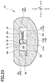
- the outer circumferential part 110a of the optical part 110 of the IOL 100 comes to contact with the inner wall surfaces 20c, and the optical part 110 is folded as valley-folded toward the bottom surface 20e (toward a rear side of the paper in FIG. 8 ).
- the front-side support part 112A of the IOL 100 comes to contact with the inner wall surfaces 20c and the root portion 116A is gradually curved by the stress applied by the inner wall surfaces 20c and folded toward the optical part 110.
- the distal end portion 118A of the front-side support part 112A is placed inside the outer circumferential part 110a of the optical part 110, so that the front-side support part 112A gets in the inside (inside the outer circumferential part 110a) of the optical part 110.
- the distal end portion 118A of the front-side support part 112A gets in a space defined by the optical part 110 and the ceiling surface 20d.
- the root portion 116A of the front-side support part 112A is placed in a position closer to the first inner wall surface 24a than the central axis Lt of the passage 20b, and on the other hand, the root portion 116B of the rear-side support part 112B is placed in a position closer to the second inner wall surface 24b than the central axis Lt of the passage 20b.
- the IOL 100 is further pushed toward the tip end 20a of the injection part 20, and as shown in FIG. 9 , the IOL 100 is rotated (counterclockwise, in a direction indicated with a bold arrow in FIG. 9 ) in such a manner that the root portion 116A of the front-side support part 112A moves away from the first inner wall surface 24a and comes close to the push-out axis Lp (the central axis Lt of the passage 20b) in a circumferential direction of the IOL 100.
- the front-side support part 112A gets in further inside of the optical part 110.
- a detailed explanation of a process that the front-side support part 112A gets in further inside of the optical part 110 shown in FIG. 9 from the state shown in FIG. 8 will be given later.
- the IOL 100 is further pushed toward the tip end 20a of the injection part 20, and as shown in FIG. 11 , the root portion 116A is further curved and the front-side support part 112A is folded and kept to be placed on top of the optical part 110 facing the ceiling surface 20d. Furthermore, the optical part 110 is folded into a tiny piece as valley-folded toward a rear side of the paper in FIG. 11 . The rear-side support part 112B is also kept to be placed on top of the optical part 110 facing the ceiling surface 20d.
- the front-side support part 112A and the rear-side support part 112B are kept to be placed on top of the optical part 110 facing the ceiling surface 20d and the optical part 110 is folded into a tiny piece as valley-folded toward the bottom surface 20e, and subsequently, the IOL 100 is pushed out of the injection part 20 through the tip end 20a of the injection part 20 and moved into the eye. In this manner, the folded IOL 100 is injected into the eye.
- a distance do is defined as a direct distance from an edge portion 117A of the root portion 116A of the front-side support part 112A facing the first inner wall surface 24a to the push-out axis Lp.
- the entering amount ⁇ 0 of the front-side support part 112A is small, and therefore, if the IOL 100 moving forward in the passage 20b is oscillated, for example, there is a possibility that the front-side support part 112A which has got in the inside of the optical part 110 comes out of the optical part 110.
- the leading end 12a of the plunger 12 moves toward the second inner wall surface 24b.
- the plunger 12 is guided by the guide face 36a of the protruding portion 36, and thereby the leading end 12a of the plunger 12 comes off the push-out axis Lp and moves closer to the second inner wall surface 24b than the push-out axis Lp.
- the protruding portion 36 directs the leading end 12a of the plunger 12 toward the second inner wall surface 24b.
- a push-out force P applied to the IOL 100 from the plunger 12 acts on the second inner wall surface 24b side of the IOL 100.
- the second inner wall surface 24b has a uniform frictional force over the whole surface, but the push-out force P applied to the optical part 110 increases a pushing force to push the optical part 110 against the second inner wall surface 24b, thereby increasing a frictional force generated between the outer circumferential part 110a of the optical part 110 and the second inner wall surface 24b (a reaction force that the outer circumferential part 110a of the optical part 110 receives from the second inner wall surface 24b).
- a contact portion of the outer circumferential part 110a of the optical part 110 contacting the second inner wall surface 24b becomes hard to move toward the tip end 20a of the injection part 20.
- a frictional force generated between the outer circumferential part 110a of the optical part 110 and the first inner wall surface 24a (a reaction force that the outer circumferential part 110a of the optical part 110 receives from the first inner wall surface 24a) is decreased, and thus a contact portion of the outer circumferential part 110a of the optical part 110 contacting the first inner wall surface 24a becomes easy to move toward the tip end 20a of the injection part 20.
- the IOL 100 is rotated in the circumferential direction of the optical part 110 such that the root portion 116A of the front-side support part 112A moves away from the first inner wall surface 24a and comes close to the push-out axis Lp.
- a direct distance from the edge portion 117A on the first inner wall surface 24a side of the root portion 116A in the front-side support part 112A to the push-out axis Lp is defined as a distance d, and this distance d is smaller than the above mentioned distance do. Further, an entering amount ⁇ 1 of the front-side support part 112A getting in the inside of the optical part 110 is large (larger than the above mentioned amount ⁇ 0).
- the entering amount ⁇ 1 of the front-side support part 112A is large, and therefore, even if the IOL 100 is oscillated during movement in the passage 20b, for example, the front-side support part 112A having got in the inside of the optical part 110 is prevented from coming out of the optical part 110.
- the IOL 100 is further pushed toward the tip end 20a of the injection part 20, as shown in FIG. 11 , the plunger 12 is curved and the leading end 12a of the plunger 12 returns onto the push-out axis Lp.
- the IOL 100 of a favorable folded shape is injected outside the injection part 20.
- the IOL 100 may only have to be injected outside the injection part 20, and the leading end 12a of the plunger 12 does not have to come out of the tip end 20a of the injection part 20, for example.
- a part of the plunger 12 that has come out may not be in a position along the push-out axis Lp.
- the protruding portion 36 directs the leading end 12a of the plunger 12 to the second inner wall surface 24b so that an orientation of the IOL 100 in the circumferential direction of the optical part 110 is controlled.
- the orientation of the IOL 100 in the circumferential direction of the optical part 110 is controlled.
- the timing is not limited to the above, and a position of the protruding portion 36 may be varied or other measures may be taken to control the orientation of the IOL 100 in the circumferential direction of the optical part 110 simultaneously with the time when the distal end portion 118A of the front-side support part 112A is placed inside the outer circumferential part 110a of the optical part 110.
- the passage 20b may be configured as an inclined passage (a lens control mechanism) in which the central axis Lt of the passage 20b intersects the push-out axis Lp.
- the central axis Lt of the passage 20b may intersect and be slanted with respect to the push-out axis Lp to the radial direction (the axis Y direction) of the optical part 110 when the IOL 100 is placed in the passage 20b.
- an inclination angle ⁇ of the central axis Lt of the passage 20b with respect to the push-out axis Lp is 5°.
- a direction of the central axis Lt of the passage 20b is defined as the axis X direction.
- each inclination of the first inner wall surface 24a and the second inner wall surface 24b with respect to the push-out axis Lp are differentiated from each other. Specifically, the inclination of the second inner wall surface 24b with respect to the push-out axis Lp is larger than that of the first inner wall surface 24a with respect to the push-out axis Lp. Further, the second inner wall surface 24b intersects the push-out axis Lp.
- the leading end 12a of the plunger 12 when the leading end 12a of the plunger 12 is pushed to move along the push-out axis Lp, the leading end 12a of the plunger 12 is directed toward the second inner wall surface 24b.
- the IOL 100 is rotated as similarly to the above mentioned example shown in FIG. 9 (see FIG. 12 ).
- the first inner wall surface 24a and the second inner wall surface 24b are formed (inclined) symmetrically with respect to the central axis Lt of the passage 20b.
- the whole passage 20b is configured as an inclined passage, but as another modified example, only a part of the passage 20b may be configured as the inclined passage.
- a part of the passage 20b closer to the tip end 20a of the injection part 20 than a predetermined point may be configured as the inclined passage.
- the IOL injection instrument 1 may be configured such that a first frictional force generated between the first inner wall surface 24a and the outer circumferential part 110a of the optical part 110 of the IOL 100 and a second frictional force generated between the second inner wall surface 24b and the outer circumferential part 110a of the optical part 110 of the IOL 100 are differentiated.
- a surface roughness of the second inner wall surface 24b is made rougher than a surface roughness of the first inner wall surface 24a so that the second frictional force is made larger than the first frictional force.
- a contact portion of the outer circumferential part 110a in the optical part 110 contacting the second inner wall surface 24b is made hard to move toward the tip end 20a of the injection part 20.
- a contact portion of the outer circumferential part 110a in the optical part 110 contacting the first inner wall surface 24a is made easy to move toward the tip end 20a of the injection part 20. Therefore, the IOL 100 is rotated as similarly to the above mentioned FIG. 9 . As a result, the entering amount ⁇ 1 of the front-side support part 112A can be increased.
- the orientation of the IOL 100 in the circumferential direction of the optical part 110 is made to be controlled.
- "when or after the distal end portion 118A is placed inside the outer circumferential part 110a of the optical part 100” means the simultaneous timing with the time when the distal end portion 118A is placed inside the outer circumferential part 110a of the optical part 110 or the timing subsequent to the time when the distal end portion 118A is placed inside the outer circumferential part 110a of the optical part 110.
- the entering amount ⁇ 1 of the front-side support part 112A getting in the inside of the optical part 110 can be controlled. Therefore, by controlling the entering amount ⁇ 1 of the front-side support part 112A to be increased, it is enabled to prevent the front-side support part 112A, which has once got in the inside of the optical part 110, from coming out of the optical part 110. Accordingly, when the IOL 100 is about to be injected, it is enabled to maintain a state in which the front-side support part 112A is folded and placed on top of the optical part 110. Thus, the IOL 100 can be appropriately deformed and injected.
- the protruding portion 36 is configured to direct the leading end 12a of the plunger 12 toward the second inner wall surface 24b so that the orientation of the IOL 100 in the circumferential direction of the optical part 110 is controlled.
- the IOL 100 is rotated in the circumferential direction of the optical part 110 such that the root portion 116A of the front-side support part 112A moves away from the first inner wall surface 24a and comes close to the push-out axis Lp. Accordingly, the entering amount ⁇ 1 of the front-side support part 112A can be effectively increased.
- the protruding portion 36 protrudes from the ceiling surface 20d toward the bottom surface 20e in the passage 20b.
- the leading end 12a of the plunger 12 is made to be in contact with the protruding portion 36, so that a moving direction of the leading end 12a of the plunger 12 can be controlled.
- the protruding portion 36 is located close to the tip end 20a of the injection part 20 in the axis X direction in the first protrusion 32 and protrudes more inwardly toward the guide portion 30 than the guide face 32b of the first protrusion 32 in the axis Y direction.
- the front end portion 36b of the protruding portion 36 is formed to extend in the axis Y direction from a position closer to the first inner wall surface 24a than the central part Ce in the passage 20b to a position closer to the second inner wall surface 24b than the central part Ce in the passage 20b across the central part Ce of the passage 20b.
- the central axis Lt of the passage 20b may be inclined toward the first inner wall surface 24a with respect to the push-out axis Lp to the radial direction (in the axis Y direction) of the optical part 110 when the IOL 100 is placed in the passage 20b.
- the plunger 12 is made to move toward the second inner wall surface 24b. Therefore, the IOL 100 is rotated in the circumferential direction of the optical part 110 such that the root portion 116A of the front-side support part 112A moves away from the first inner wall surface 24a and comes close to the push-out axis Lp. Accordingly, the entering amount ⁇ 1 of the front-side support part 112A can be effectively increased.
- first frictional force generated between the first inner wall surface 24a and the outer circumferential part 110a of the optical part 110 and the second frictional force generated between the second inner wall surface 24b and the outer circumferential part 110a of the optical part 110 may be differentiated.
- the IOL 100 is rotated in the circumferential direction of the optical part 110 such that the root portion 116A of the front-side support part 112A moves away from the first inner wall surface 24a and comes close to the push-out axis Lp.
- the entering amount ⁇ 1 of the front-side support part 112A can be increased.
- the leading end 12a of the plunger 12 may be moved toward the first inner wall surface 24a so as to rotate the IOL 100 in the circumferential direction of the optical part 110 such that the root portion 116A of the front-side support part 112A moves away from the first inner wall surface 24a and comes close to the push-out axis Lp.
- the second protrusion 34 constitutes one wall surface (a lower side in FIG. 14 , a side of the first inner wall surface 24a) of the guide portion 30, and the first protrusion 32 constitutes the other wall surface (an upper side in FIG. 14 , a side of the second inner wall surface 24b) of the guide portion 30.
- the leading end 12a of the plunger 12 is directed toward the first inner wall surface 24a.
- the plunger 12 is guided by the guide face 36a of the protruding portion 36 as shown in FIG. 15 , and thus the leading end 12a of the plunger 12 comes off the push-out axis Lp and comes closer to the first inner wall surface 24a than the push-out axis Lp. Therefore, the protruding portion 36 directs the leading end 12a of the plunger 12 toward the first inner wall surface 24a.
- the push-out force P applied to the IOL 100 by the plunger 12 acts on the IOL 100 on the side of the first inner wall surface 24a.
- the first inner wall surface 24a has a uniform frictional force over the whole surface and the frictional force is small enough by an application of coating or the like. Accordingly, the IOL 100 is rotated in the circumferential direction of the optical part 110 by the push-out force P such that the root portion 116A of the front-side support part 112A moves away from the first inner wall surface 24a and comes close to the push-out axis Lp.
- the protruding portion 36 directs the leading end 12a of the plunger 12 to move toward the first inner wall surface 24a, and thereby the orientation of the IOL 100 in the circumferential direction of the optical part 110 is controlled.
- the IOL 100 is rotated in the circumferential direction of the optical part 110 such that the root portion 116A of the front-side support part 112A moves away from the first inner wall surface 24a and comes close to the push-out axis Lp. Therefore, the entering amount ⁇ 1 of the front-side support part 112A can be effectively increased.
- the passage 20b may be configured as an inclined passage (a lens control mechanism) of which the central axis Lt of the passage 20b intersects the push-out axis Lp.
- an inclination of the first inner wall surface 24a with respect to the push-out axis Lp is made larger than that of the second inner wall surface 24b with respect to the push-out axis Lp.
- the first inner wall surface 24a intersects the push-out axis Lp.
- the leading end 12a of the plunger 12 when the leading end 12a of the plunger 12 is moved forward on the push-out axis Lp, the leading end 12a of the plunger 12 is directed toward the first inner wall surface 24a.
- the leading end 12a of the plunger 12 is directed toward the first inner wall surface 24a in this manner, the IOL 100 is rotated as similarly to the above mentioned FIG. 15 (see FIG. 16 ).
- the central axis Lt of the passage 20b may be inclined with respect to the push-out axis Lp toward the second inner wall surface 24b to the radial direction (in the axis Y direction) of the optical part 110 when the IOL 100 is placed in the passage 20b.
- the plunger 12 can be moved toward the first inner wall surface 24a.
- the IOL 100 is rotated in the circumferential direction of the optical part 110 such that the root portion 116A of the front-side support part 112A moves away from the first inner wall surface 24a and comes close to the push-out axis Lp. Accordingly, the entering amount ⁇ 1 of the front-side support part 112A can be effectively increased.
- the technique illustrated in the above embodiment may be adopted for an IOL injection instrument of a preset type in which an IOL 100 is loaded inside in advance and for an IOL injection instrument which is to be supplied or shipped without preloading the IOL 100.
- the IOL 100 illustrated in the above embodiment is a one-piece IOL in which the optical part 110, the front-side support part 112A, and the rear-side support part 112B are integrally formed.
- the technique illustrated in the above embodiment may be applied to an IOL injection instrument for injecting an intraocular lens other than a one-piece type (for example, a 3-piece IOL and others).
- the root portions 116A and 116B of the IOL 100 may be directly connected to the outer circumferential part of the optical part 110 without providing the connecting portions 114A and 114B.
- the setting part 22 is, as shown in FIGs. 17 to 19 , provided with the passage 22a, the ceiling surface 22b, the bottom surface 22c, the inner wall surface 22d (a rear-side inner wall surface), the guide portion 30, a first guide protrusion 33, a second guide protrusion 35, a first protrusion 40, a second protrusion 42, and others.
- the inner wall surfaces 22d are formed on both sides in a direction orthogonal to the central axis Lt of the passage 22a, the direction being parallel to the radial direction of the optical part 110 when the IOL 100 is placed in the passage 22a.
- the first inner wall surface 26a is provided on a side where the root portion 116A of the front-side support part 112A is placed in the passage 22a with respect to the central axis Lt of the passage 22a when the IOL 100 is placed therein.
- the second inner wall surface 26b is provided on a side where the root portion 116B of the rear-side support part 112B is placed in the passage 22a with respect to the central axis Lt of the passage 22a when the IOL 100 is placed therein.
- the guide portion 30 is formed on the ceiling surface 22b to guide the push-out direction of the plunger 12.
- the first guide protrusion 33 and the second guide protrusion 35 are formed along the push-out direction of the plunger 12.
- the first guide protrusion 33 constitutes one wall surface (a lower side in FIG. 17 ) of the guide portion 30 and protrudes from the ceiling surface 22b toward the bottom surface 22c (toward a front side of the paper in FIG. 17 ).
- the second guide protrusion 35 constitutes the other wall surface (an upper side in FIG. 17 ) of the guide portion 30 and protrudes from the ceiling surface 22b toward the bottom surface 22c (toward the front side of the paper in FIG. 17 ).
- the first protrusion 40 is, as shown in FIG. 17 , formed to protrude from the first inner wall surface 26a toward the central axis Lt of the passage 22a. Further, as shown in FIG. 19 , the first protrusion 40 is formed to protrude from the ceiling surface 22b toward the bottom surface 22c. In an example shown in FIG. 17 , the first protrusion 40 is formed to be in an elongated shape extending in parallel with the central axis Lt of the passage 22a in an end portion of the passage 22a close to the injection part 20.
- the first protrusion 40 has an inside surface 40a (a first contact portion, an optical contact portion) and a slope portion 40b.
- the inside surface 40a is formed on an end face of the first protrusion 40 which protrudes from the first inner wall surface 26a toward the central axis Lt of the passage 22a.
- the inside surface 40a of the first protrusion 40 is formed in a position closer to the central axis Lt of the passage 22a than the first inner wall surface 26a, namely, formed between the first inner wall surface 26a and the central axis Lt of the passage 22a.
- the inside surface 40a of the first protrusion 40 is provided between the first inner wall surface 26a and the first guide protrusion 33.
- a distance D between the inside surface 40a of the first protrusion 40 and the central axis Lt of the passage 22a is made to be shorter than a radius of the optical part 110. Further, the inside surface 40a of the first protrusion 40 is arranged in a position to be in contact with the outer circumferential part 110a of the optical part 110 when the IOL 100 is pushed out which will be explained later.
- the slope portion 40b is provided on a rear end portion of the first protrusion 40 in the push-out direction of the plunger 12 such that a protruding amount of the slope portion 40b protruding from the first inner wall surface 26a to the central axis Lt of the passage 22a is gradually increased as coming close to a front side of the push-out direction of the plunger 12.
- the slope portion 40b is formed in an inclined direction with respect to the push-out direction of the plunger 12.
- the second protrusion 42 is, as shown in FIG. 17 , provided on the side closer to the central axis Lt of the passage 22a and the passage 20b than the second inner wall surface 26b and the second inner wall surface 24b. As shown in FIG. 19 , the second protrusion 42 is formed to protrude from the ceiling surface 22b toward the bottom surface 22c.
- the second protrusion 42 is, as shown in FIG. 17 , formed in an elongated shape extending in parallel with the central axis Lt of the passage 20b and the passage 22a in a portion including a boundary portion of the passage 22a and the passage 20b.
- the second protrusion 42 includes an inside surface 42a (a second contact portion, a support contact portion).
- the inside surface 42a is a surface formed on a side of the central axis Lt of the passage 22a in the second protrusion 42.
- the inside surface 42a of the second protrusion 42 is thus provided in a position closer to the central axis Lt of the passage 22a than the second inner wall surface 26b, namely, provided between the second inner wall surface 26b and the central axis Lt of the passage 22a.
- a part of the inside surface 42a of the second protrusion 42 is positioned between the second inner wall surface 26b and the second guide protrusion 35.
- the inside surface 42a of the second protrusion 42 is positioned to be in contact with the root portion 116B of the rear-side support part 112B on the second inner wall surface 26b side when or after the outer circumferential part 110a of the optical part 110 moves away from the inside surface 40a of the first protrusion 40 and when the front-side support part 112A and the optical part 110 are placed in the passage 20b during the push-out operation of the IOL 100 which will be mentioned later.
- the axes X, Y, and Z which are orthogonally intersecting one another are assumed, and a direction indicated with the axis X is defined as a direction parallel to the push-out direction of the IOL 100 (the central axis Lt direction of the passage 20b and the passage 22a, the push-out axis Lp direction).
- the passage 20b is surrounded by the two inner wall surfaces 20c (the first inner wall surface 24a and the second inner wall surface 24b) formed on both sides in the axis Y direction, the ceiling surface 20d and the bottom surface 20e formed on both sides in the axis Z direction, and others.
- the passage 22a is formed to be surrounded by the two inner wall surfaces 22d (the first inner wall surface 26a and the second inner wall surface 26b) formed on both sides in the axis Y direction, the ceiling surface 22b and the bottom surface 22c formed on both sides in the axis Z direction (see FIG. 19 ), and others.
- An operator who operates the injector 1 firstly places the IOL 100 in the passage 22a of the setting part 22 as shown in FIG. 18 such that the front-side support part 112A is positioned on the side closer to the tip end 20a of the injection part 20 than the optical part 110.
- the root portion 116A of the front-side support part 112A is in contact with the first inner wall surface 26a of the setting part 22 and there is no clearance formed between the root portion 116A of the front-side support part 112A and the first inner wall surface 26a of the setting part 22.
- the operator then pushes the rear-side support part 112B by the plunger 12.
- the root portion 116B of the rear-side support part 112B is curved and the rear-side support part 112B is folded inside the outer circumferential part 110a of the optical part 110 and placed on top of the optical part 110.
- the IOL 100 is placed in the passage 22a with the rear-side support part 112B being folded inside the optical part 110.
- the operator further pushes the outer circumferential part 110a of the optical part 110 by the plunger 12.
- the root portion 116A of the front-side support part 112A is brought into contact with the inside surface 40a of the first protrusion 40 while the IOL 100 is pushed toward the tip end 20a of the injection part 20.
- the outer circumferential part 110a of the optical part 110 is guided by the slope portion 40b of the first protrusion 40, and the IOL 100 is pushed toward the tip end 20a of the injection part 20.
- an edge portion 120 of the outer circumferential part 110a of the optical part 110 on the first inner wall surface 26a side comes to contact with the inside surface 40a of the first protrusion 40.
- the optical part 110 is pushed by the first protrusion 40 and directed toward the second inner wall surface 26b. Therefore, the optical axis L of the optical part 110 comes off the central axis Lt of the passage 22a and moves to a position apart from the central axis Lt by a distance ⁇ (see FIG. 21 ) on the second inner wall surface 26b side.
- the root portion 116A of the front-side support part 112A moves away from the first inner wall surface 26a.
- a clearance C0 is created between the root portion 116A of the front-side support part 112A and the first inner wall surface 26a. Accordingly, the root portion 116A of the front-side support part 112A is not interfered by the first inner wall surface 26a.
- clearance C0 thus makes it easy to subsequently form a clearance C1 between the root portion 116A of the front-side support part 112A and the first inner wall surface 24a when the IOL 100 is pushed into the passage 20b by the plunger 12.
- the IOL 100 is pushed into the passage 20b from the passage 22a.
- the outer circumferential part 110a of the optical part 110 comes away from the inside surface 40a of the first protrusion 40, and the front-side support part 112A and the optical part 110 are moved into the passage 20b of the injection part 20.
- the optical part 110 is free from pushing by the first protrusion 40, and thereby moves toward the first inner wall surface 24a (the first inner wall surface 26a).
- the optical axis L of the optical part 110 is moved in a position of the central axis Lt of the passage 20b (the passage 22a).
- the optical part 110 gets free from pushing by the first protrusion 40 and comes to contact with the inner wall surfaces 20c of the injection part 20 to be subjected to the stress by the inner wall surfaces 20c. Therefore, the optical part 110 is intended to rotate (about the optical axis L, for example) in a direction which the root portion 116B of the rear-side support part 112B comes close to the second inner wall surface 26b (in a clockwise direction in FIG. 22 ).
- the inside surface 42a of the second protrusion 42 is in contact with the root portion 116B of the rear-side support part 112B, and therefore the optical part 110 is restrained from rotation in the direction which the root portion 116B of the rear-side support part 112B comes close to the second inner wall surface 26b.
- the clearance C0 is formed and maintained between the root portion 116A of the front-side support part 112A and the first inner wall surface 26a of the setting part 22, and therefore a clearance C1 is also formed between the root portion 116A of the front-side support part 112A and the first inner wall surface 24a of the injection part 20. Accordingly, the root portion 116A of the front-side support part 112A is not interfered by the first inner wall surface 24a.
- the optical part 110 is pushed by the first protrusion 40, and hence the clearance C0 is formed between the root portion 116A of the front-side support part 112A and the first inner wall surface 26a.
- the clearance C1 becomes easy to be formed between the root portion 116A of the front-side support part 112A and the first inner wall surface 24a.
- the second protrusion 42 restrains the optical part 110 from rotation in the direction which the root portion 116B of the rear-side support part 112B comes close to the second inner wall surface 26b, and thus the clearance C1 becomes easy to be formed between the root portion 116A of the front-side support part 112A and the first inner wall surface 24a of the injection part 20.
- the first protrusion 40 pushes the optical part 110
- the second protrusion 42 restrains the optical part 110 from rotation in the direction which the root portion 116B of the rear-side support part 112B comes close to the second inner wall surface 26b. Therefore, even after the optical part 110 is separated from the first protrusion 40, the posture of the IOL 100 is unchanged from the state when the optical part 110 was in contact with the first protrusion 40. Accordingly, the clearance C1 becomes easy to be formed between the root portion 116A of the front-side support part 112A and the first inner wall surface 24a of the injection part 20.
- the outer circumferential part 110a of the optical part 110 is brought into contact with the inner wall surfaces 20c of the injection part 20, and the optical part 110 is folded as valley-folded toward the bottom surface 20e (toward a rear side of the paper in FIG. 24 ).
- the front-side support part 112A comes to contact with the second inner wall surface 24b, and thereby the root portion 116A is gradually curved and folded toward the optical part 110.
- the clearance C1 is formed between the root portion 116A of the front-side support part 112A and the first inner wall surface 24a. Therefore, during the push-out operation of the IOL 100, the root portion 116A of the front-side support part 112A is not interfered by the first inner wall surface 24a. While the root portion 116A of the front-side support part 112A is not interfered by the first inner wall surface 24a, the distal end portion 118A of the front-side support part 112A is firmly pressed by the second inner wall surface 24b.
- the distal end portion 118A of the front-side support part 112A is easily subjected to the stress by the second inner wall surface 24b. Accordingly, the distal end portion 118A of the front-side support part 112A is guided to the inside of the optical part 110, and thus an entering amount of the front-side support part 112A getting in the inside of the optical part 110 is increased as shown in FIG. 24 .
- This increase in the entering amount of the front-side support part 112A getting in the inside of the optical part 110 contributes to subsequently maintaining the front-side support part 112A to be placed on the surface of the optical part 110 on the ceiling surface 20d side.
- the distal end portion 118A of the front-side support part 112A is made to be placed inside the outer circumferential part 110a of the optical part 110 so that the front-side support part 112A gets in the inside of the optical part 110 (more inward than the outer circumferential part 110a).
- the distal end portion 118A of the front-side support part 112A enters into a space between the optical part 110 and the ceiling surface 20d.
- the IOL 100 is further pushed toward the tip end 20a of the injection part 20, and then the optical part 110 is further folded as valley-folded as shown in FIG. 25 .
- the root portion 116A of the front-side support part 112A has a possibility of being folded and inwardly twisted in the passage 20b in conformity with a shape of the first inner wall surface 24a.
- the front-side support part 112A having an elastic force attempts to extend to relieve the twisted state.
- the front-side support part 112A comes out of the optical part 110.
- the clearance C1 is formed between the root portion 116A of the front-side support part 112A and the first inner wall surface 24a, and the root portion 116A of the front-side support part 112A is hence separated from the first inner wall surface 24a. Therefore, the root portion 116A of the front-side support part 112A is hardly twisted and folded inwardly in the passage 20b in conformity with the shape of the first inner wall surface 24a. Further, the root portion 116A of the front-side support part 112A is in a rising position (an outer circumferential surface 119A of the root portion 116A is placed on a front side of the paper in FIG. 25 ) following valley-folding of the optical part 110. This rising position of the root portion 116A of the front-side support part 112A makes it easy to subsequently maintain a state in which the front-side support part 112A is placed on the surface of the optical part 110 on the ceiling surface 20d side.
- the IOL 100 is further pushed toward the tip end 20a of the injection part 20, and as shown in FIG. 26 , the root portion 116A is further curved to fold the front-side support part 112A, and the front-side support part 112A is kept to be placed on top of the optical part 110 on the ceiling surface 20d side. Further, the optical part 110 is further valley-folded toward the rear side of the paper in FIG. 26 to be folded into a tiny piece. Incidentally, the rear-side support part 112B is also kept to be placed on top of the optical part 110 on the ceiling surface 20d side.
- the entering amount of the front-side support part 112A getting in the inside of the optical part 110 is increased as shown in the above mentioned FIG. 24 , and the root portion 116A of the front-side support part 112A is in the rising position as shown in the above mentioned FIG. 25 . Accordingly, even if the IOL 100 being pushed in the passage 20b is oscillated, it is enabled to maintain the state in which the front-side support part 112A is placed on top of the optical part 110 on the ceiling surface 20d side.
- the IOL 100 is further pushed toward the tip end 20a of the injection part 20, while the front-side support part 112A and the rear-side support part 112B are placed on top of the optical part 110 on the ceiling surface 20d side and the optical part 110 is valley-folded toward the bottom surface 20e into a tiny piece, the IOL 100 is pushed out of the injection part 20 through the tip end 20a of the injection part 20 and moved into the eye. In this manner, the folded IOL 100 is injected into the eye.
- the above mentioned embodiment illustrates an example that after the outer circumferential part 110a of the optical part 110 moves away from the inside surface 40a of the first protrusion 40, the root portion 116B of the rear-side support part 112B comes to contact with the inside surface 42a of the second protrusion 42.
- the root portion 116B of the rear-side support part 112B may be configured to come to contact with the inside surface 42a of the second protrusion 42 simultaneously with the time when the outer circumferential part 110a of the optical part 110 moves away from the inside surface 40a of the first protrusion 40.
- first protrusion 40 may be formed separately from the first inner wall surface 26a in a position between the first inner wall surface 26a and the central axis Lt of the passage 22a.
- second protrusion 42 may be formed to protrude from the second inner wall surface 26b toward the central axis Lt of the passage 22a.
- the inside surface 40a of the first protrusion 40 is formed in a position closer to the central axis Lt of the passage 22a than the first inner wall surface 26a. Further, the inside surface 40a of the first protrusion 40 is formed to be brought into contact with the outer circumferential part 110a of the optical part 110 during the push-out operation of the IOL 100.
- the optical part 110 is pushed by the first protrusion 40 and thus moved toward the central axis Lt of the passage 22a from the first inner wall surface 26a side.
- the clearance C0 is formed between the root portion 116A of the front-side support part 112A and the first inner wall surface 26a. Accordingly, after that, when the IOL 100 is pushed toward the tip end 20a in the passage 20b of the injection part 20, the clearance C1 is easily formed between the root portion 116A of the front-side support part 112A and the first inner wall surface 24a. This clearance C1 therefore prevents the root portion 116A of the front-side support part 112A from being interfered by the first inner wall surface 24a.
- the root portion 116A of the front-side support part 112A is thus hard to be interfered by the first inner wall surface 24a, and on the other hand, the distal end portion 118A of the front-side support part 112A is firmly pressed against the second inner wall surface 24b. Therefore, the distal end portion 118A of the front-side support part 112A is easily subjected to the stress by the second inner wall surface 24b.
- the distal end portion 118A of the front-side support part 112A is hence guided to the inside of the optical part 110, and thus the entering amount of the front-side support part 112A getting in the inside of the optical part 110 is increased.
- This increased entering amount of the front-side support part 112A getting in the inside of the optical part 110 contributes to subsequently maintaining the state in which the front-side support part 112A is placed on top of the optical part 110 on the ceiling surface 20d side. Accordingly, the IOL 100 can be folded into a tiny piece with the front-side support part 112A (and the rear-side support part 112B) being folded and placed on the optical part 110. As a result, the IOL 100 can be appropriately deformed and injected.
- the distance D between the inside surface 40a of the first protrusion 40 and the central axis Lt of the passage 22a is shorter than the radius of the optical part 110. Therefore, when the outer circumferential part 110a of the optical part 110 comes to contact with the inside surface 40a of the first protrusion 40, the optical axis L of the optical part 110 comes off the central axis Lt of the passage 22a and moves closer to the second inner wall surface 26b than the central axis Lt. As a result, the clearance C0 is formed between the root portion 116A of the front-side support part 112A and the first inner wall surface 26a.
- the inside surface 40a of the first protrusion 40 is formed in a peripheral end portion of the first protrusion 40 protruding toward the central axis Lt of the passage 22a from the first inner wall surface 26a.
- the optical part 110 is pushed by the first protrusion 40, and thus the clearance C0 is formed between the root portion 116A of the front-side support part 112A and the first inner wall surface 26a. Accordingly, after that, when the front-side support part 112A is placed in the passage 20b, the clearance C1 becomes easy to be formed between the root portion 116A of the front-side support part 112A and the first inner wall surface 24a.
- the inside surface 42a of the second protrusion 42 is formed on a side closer to the central axis Lt of the passage 22a than the second inner wall surface 26b.
- the inside surface 42a of the second protrusion 42 is positioned to be brought into contact with the root portion 116B of the rear-side support part 112B on the second inner wall surface 26b side when or after the outer circumferential part 110a of the optical part 110 is separated from the inside surface 40a of the first protrusion 40 during the push-out operation of the IOL 100.
- the posture of the IOL 100 (a circumferential direction of the optical part 110) is unchanged from the posture when the optical part 110 was in contact with the first protrusion 40.
- the clearance C1 is formed between the root portion 116A of the front-side support part 112A and the first inner wall surface 24a of the injection part 20. Therefore, the root portion 116A of the front-side support part 112A is not interfered by the first inner wall surface 24a, and thus the front-side support part 112A becomes easily folded inside the optical part 110. Accordingly, the front-side support part 112A becomes easily placed on the surface of the optical part 110 on the ceiling surface 20d side.
- the inside surface 42a of the second protrusion 42 is formed to be brought into contact with the root portion 116B of the rear-side support part 112B when the front-side support part 112A and the optical part 110 are placed in the passage 20b of the injection part 20 during the push-out operation of the IOL 100.
- the posture of the IOL 100 is unchanged from the state when the optical part 110 was in contact with the first protrusion 40.
- An intraocular lens injection instrument for injecting an intraocular lens into an eye, the intraocular lens comprising an optical part of a disk-like shape and a first support part extending outwardly from an outer circumferential part of the optical part, characterized in that the intraocular lens injection instrument comprises:
- the intraocular lens injection instrument according to the supplementary claim 1, characterized in that a distance between the first contact portion and the central axis of the rear-side passage is shorter than a radius of the optical part.
- the intraocular lens injection instrument according to the supplementary claim 1 or 2, characterized in that the first contact portion is formed in a distal end portion of a protrusion protruding from the first inner wall surface toward the central axis of the rear-side passage.
- the intraocular lens injection instrument characterized in that the intraocular lens further comprises a second support part extending outwardly from the outer circumferential part of the optical part, the first support part and the second support part are formed in point-symmetrical positions with reference to a center of the optical part, the second support part is folded inside the optical part in the rear-side passage and the intraocular lens is pushed toward the front-side passage during injection of the intraocular lens into the eye, the second inner wall surface is provided on a side where a root portion of the second support part is placed in the rear-side passage with respect to the central axis of the rear-side passage when the intraocular lens is placed therein, a second contact portion is formed closer to the central axis of the rear-side passage than the second inner wall surface, and the second contact portion is formed to be in contact with the root portion of the second support part when or after the outer circumferential part of the optical part moves away from the first contact portion during the push-out operation of the intraocular
- the intraocular lens injection instrument according to the supplementary claim 4, characterized in that the second contact portion is formed to be in contact with the root portion of the second support part when the first support part and the optical part are placed in the front-side passage during the push-out operation of the intraocular lens.
- the setting part 22 may not be provided with the first protrusion 40 but may be provided only with the second protrusion 42.
- the inside surface 42a of the second protrusion 42 comes to contact with the root portion 116B of the rear-side support part 112B, and thereby the orientation of the IOL 100 relative to the circumferential direction of the optical part 110 is controlled. Therefore, as shown in the above mentioned FIG. 22 , the orientation of the IOL 100 in the circumferential direction of the optical part 110 is enabled to be controlled such that the clearance C1 is formed between the root portion 116A of the front-side support part 112A and the first inner wall surface 24a of the injection part 20.
- An intraocular lens injection instrument for injecting an intraocular lens into an eye, the intraocular lens comprising an optical part of a disk-like shape and a first support part and a second support part both extending outwardly from an outer circumferential part of the optical part and being formed in point-symmetrical positions with reference to a center of the optical part, characterized in that the intraocular lens injection instrument comprises:
- the injector 1 of the present embodiment includes the protruding portion 36, the first protrusion 40, and the second protrusion 42.
- the optical part 110 is pushed by the first protrusion 40, and hence the clearance C0 is formed between the root portion 116A of the front-side support part 112A and the first inner wall surface 26a.
- the posture of the IOL 100 is maintained by the second protrusion 42, and thus the clearance C1 is formed between the root portion 116A of the front-side support part 112A and the first inner wall surface 24a. Therefore, the root portion 116A of the front-side support part 112A is hard to be interfered by the first inner wall surface 24a.
- the leading end 12a of the plunger 12 is directed toward the first inner wall surface 24a or the second inner wall surface 24b by the protruding portion 36, so that the orientation of the IOL 100 in the circumferential direction of the optical part 110 is easily controlled. Accordingly, the IOL 100 is easily rotated in the circumferential direction of the optical part 110 such that the root portion 116A of the front-side support part 112A moves away from the first inner wall surface 24a and comes close to the push-out axis Lp.
- the entering amount ⁇ 1 of the front-side support part 112A can be controlled to be large, and hence the front-side support part 112A is kept to be folded and placed on top of the optical part 110 when the IOL 100 is about to be injected into the eye. Accordingly, the IOL 100 can be appropriately deformed and injected.
- An embodiment combining the first and second embodiments is not limited to the above third embodiment. At least any one of configurations included in the first embodiment and any one of configurations included in the second embodiment may be combined.
- the injector 1 may only include the protruding portion 36 and the first protrusion 40. Namely, the injector 1 configured by combining the first and second embodiments may not include the second protrusion 42.
- the injector 1 may be embodied in such a way that the optical part 110 is pressed by the first protrusion 40, and the protruding portion 36 directs the leading end 12a of the plunger 12 toward first inner wall surface 24a or the second inner wall surface 24b.
Landscapes
- Health & Medical Sciences (AREA)
- Ophthalmology & Optometry (AREA)
- Cardiology (AREA)
- Oral & Maxillofacial Surgery (AREA)
- Transplantation (AREA)
- Engineering & Computer Science (AREA)
- Biomedical Technology (AREA)
- Heart & Thoracic Surgery (AREA)
- Vascular Medicine (AREA)
- Life Sciences & Earth Sciences (AREA)
- Animal Behavior & Ethology (AREA)
- General Health & Medical Sciences (AREA)
- Public Health (AREA)
- Veterinary Medicine (AREA)
- Prostheses (AREA)
Priority Applications (1)
| Application Number | Priority Date | Filing Date | Title |
|---|---|---|---|
| EP19190360.8A EP3590469A1 (fr) | 2015-03-30 | 2016-03-29 | Instrument d'injection de lentille intraoculaire |
Applications Claiming Priority (3)
| Application Number | Priority Date | Filing Date | Title |
|---|---|---|---|
| JP2015069156 | 2015-03-30 | ||
| JP2015069149 | 2015-03-30 | ||
| JP2016040327A JP6701813B2 (ja) | 2015-03-30 | 2016-03-02 | 眼内レンズ挿入器具 |
Related Child Applications (2)
| Application Number | Title | Priority Date | Filing Date |
|---|---|---|---|
| EP19190360.8A Division-Into EP3590469A1 (fr) | 2015-03-30 | 2016-03-29 | Instrument d'injection de lentille intraoculaire |
| EP19190360.8A Division EP3590469A1 (fr) | 2015-03-30 | 2016-03-29 | Instrument d'injection de lentille intraoculaire |
Publications (2)
| Publication Number | Publication Date |
|---|---|
| EP3075353A1 true EP3075353A1 (fr) | 2016-10-05 |
| EP3075353B1 EP3075353B1 (fr) | 2020-02-12 |
Family
ID=55640617
Family Applications (2)
| Application Number | Title | Priority Date | Filing Date |
|---|---|---|---|
| EP19190360.8A Pending EP3590469A1 (fr) | 2015-03-30 | 2016-03-29 | Instrument d'injection de lentille intraoculaire |
| EP16162653.6A Active EP3075353B1 (fr) | 2015-03-30 | 2016-03-29 | Instrument d'injection de lentille intraoculaire |
Family Applications Before (1)
| Application Number | Title | Priority Date | Filing Date |
|---|---|---|---|
| EP19190360.8A Pending EP3590469A1 (fr) | 2015-03-30 | 2016-03-29 | Instrument d'injection de lentille intraoculaire |
Country Status (1)
| Country | Link |
|---|---|
| EP (2) | EP3590469A1 (fr) |
Cited By (7)
| Publication number | Priority date | Publication date | Assignee | Title |
|---|---|---|---|---|
| US10172706B2 (en) | 2015-10-31 | 2019-01-08 | Novartis Ag | Intraocular lens inserter |
| US10188506B2 (en) | 2012-06-04 | 2019-01-29 | Alcon Pharmaceuticals, Ltd. | Intraocular lens inserter |
| US10568735B2 (en) | 2017-01-13 | 2020-02-25 | Alcon Inc. | Intraocular lens injector |
| US10588780B2 (en) | 2015-03-04 | 2020-03-17 | Alcon Inc. | Intraocular lens injector |
| US11000367B2 (en) | 2017-01-13 | 2021-05-11 | Alcon Inc. | Intraocular lens injector |
| CN113507901A (zh) * | 2019-01-25 | 2021-10-15 | 爱博诺德(北京)医疗科技股份有限公司 | 人工晶体植入器与预装式人工晶体植入装置 |
| EP3834775A4 (fr) * | 2018-08-07 | 2022-08-31 | Santen Pharmaceutical Co., Ltd. | Instrument d'insertion de lentille intraoculaire |
Citations (4)
| Publication number | Priority date | Publication date | Assignee | Title |
|---|---|---|---|---|
| JP2010082288A (ja) | 2008-09-30 | 2010-04-15 | Nidek Co Ltd | 眼内レンズ挿入器具 |
| US20120221102A1 (en) * | 2009-10-22 | 2012-08-30 | Menicon Co., Ltd. | Intraocular lens insertion device |
| US20140135783A1 (en) * | 2012-11-09 | 2014-05-15 | Bausch & Lomb Incorporated | Hingeless Cartridge For Intraocular Lens Injector Providing Haptic Control |
| US20140194890A1 (en) * | 2009-01-07 | 2014-07-10 | Hoya Corporation | Intraocular lens insertion device |
-
2016
- 2016-03-29 EP EP19190360.8A patent/EP3590469A1/fr active Pending
- 2016-03-29 EP EP16162653.6A patent/EP3075353B1/fr active Active
Patent Citations (4)
| Publication number | Priority date | Publication date | Assignee | Title |
|---|---|---|---|---|
| JP2010082288A (ja) | 2008-09-30 | 2010-04-15 | Nidek Co Ltd | 眼内レンズ挿入器具 |
| US20140194890A1 (en) * | 2009-01-07 | 2014-07-10 | Hoya Corporation | Intraocular lens insertion device |
| US20120221102A1 (en) * | 2009-10-22 | 2012-08-30 | Menicon Co., Ltd. | Intraocular lens insertion device |
| US20140135783A1 (en) * | 2012-11-09 | 2014-05-15 | Bausch & Lomb Incorporated | Hingeless Cartridge For Intraocular Lens Injector Providing Haptic Control |
Cited By (9)
| Publication number | Priority date | Publication date | Assignee | Title |
|---|---|---|---|---|
| US10188506B2 (en) | 2012-06-04 | 2019-01-29 | Alcon Pharmaceuticals, Ltd. | Intraocular lens inserter |
| US10485657B2 (en) | 2012-06-04 | 2019-11-26 | Alcon Pharmaceuticals, Ltd. | Intraocular lens inserter |
| US10588780B2 (en) | 2015-03-04 | 2020-03-17 | Alcon Inc. | Intraocular lens injector |
| US10172706B2 (en) | 2015-10-31 | 2019-01-08 | Novartis Ag | Intraocular lens inserter |
| US10568735B2 (en) | 2017-01-13 | 2020-02-25 | Alcon Inc. | Intraocular lens injector |
| US11000367B2 (en) | 2017-01-13 | 2021-05-11 | Alcon Inc. | Intraocular lens injector |
| EP3834775A4 (fr) * | 2018-08-07 | 2022-08-31 | Santen Pharmaceutical Co., Ltd. | Instrument d'insertion de lentille intraoculaire |
| CN113507901A (zh) * | 2019-01-25 | 2021-10-15 | 爱博诺德(北京)医疗科技股份有限公司 | 人工晶体植入器与预装式人工晶体植入装置 |
| CN113507901B (zh) * | 2019-01-25 | 2024-04-19 | 爱博诺德(北京)医疗科技股份有限公司 | 人工晶体植入器与预装式人工晶体植入装置 |
Also Published As
| Publication number | Publication date |
|---|---|
| EP3075353B1 (fr) | 2020-02-12 |
| EP3590469A1 (fr) | 2020-01-08 |
Similar Documents
| Publication | Publication Date | Title |
|---|---|---|
| EP3075353B1 (fr) | Instrument d'injection de lentille intraoculaire | |
| JP4727497B2 (ja) | 眼内挿入用レンズの挿入器具 | |
| EP2343029B1 (fr) | Instrument d'injection de lentille intraoculaire | |
| EP2957262B1 (fr) | Instrument d'injection de lentille intraoculaire | |
| RU2338486C2 (ru) | Внутриглазная линза и инжектор для ее введения | |
| WO2007037223A1 (fr) | Instrument pour insérer un cristallin artificiel | |
| JP6958668B2 (ja) | 眼内レンズ挿入器具 | |
| JP2006333981A (ja) | 眼内挿入用レンズの挿入器具 | |
| JP2004188194A (ja) | 眼内レンズインジェクタのためのピストンニードル | |
| EP2574308A2 (fr) | Instrument d'injection de lentille intraoculaire | |
| JP6027535B2 (ja) | 眼内レンズの挿入器具 | |
| JP6458409B2 (ja) | 眼内レンズ挿入器具 | |
| JP2009160191A (ja) | 眼内レンズ挿入器具 | |
| AU2018274877B2 (en) | Male form as an attachment element for an injector, and injector for implanting an intraocular lens in an eye | |
| JP4595136B2 (ja) | 眼内挿入用レンズの挿入器具 | |
| EP4112007A1 (fr) | Instrument d'insertion de lentille intraoculaire | |
| JP2010017459A (ja) | 眼内挿入用レンズの挿入器具及び眼内挿入用レンズ内装型挿入器具 | |
| US10213295B2 (en) | Intraocular lens insertion apparatus | |
| JP6669346B2 (ja) | 眼内レンズ挿入器具 | |
| JP2008289672A (ja) | 眼内挿入用レンズの挿入器具 | |
| US20210267753A1 (en) | Intraocular lens insertion apparatus | |
| US20070010879A1 (en) | Injector system for a lens | |
| US20220117725A1 (en) | Intraocular lens implanter and preloaded type intraocular lens implantation device | |
| US20180221142A1 (en) | Intraocular lens inserter cartridge with an iol-guiding structure | |
| WO2017030139A1 (fr) | Instrument d'insertion de lentille intraoculaire |
Legal Events
| Date | Code | Title | Description |
|---|---|---|---|
| PUAI | Public reference made under article 153(3) epc to a published international application that has entered the european phase |
Free format text: ORIGINAL CODE: 0009012 |
|
| AK | Designated contracting states |
Kind code of ref document: A1 Designated state(s): AL AT BE BG CH CY CZ DE DK EE ES FI FR GB GR HR HU IE IS IT LI LT LU LV MC MK MT NL NO PL PT RO RS SE SI SK SM TR |
|
| AX | Request for extension of the european patent |
Extension state: BA ME |
|
| STAA | Information on the status of an ep patent application or granted ep patent |
Free format text: STATUS: REQUEST FOR EXAMINATION WAS MADE |
|
| 17P | Request for examination filed |
Effective date: 20170403 |
|
| RBV | Designated contracting states (corrected) |
Designated state(s): AL AT BE BG CH CY CZ DE DK EE ES FI FR GB GR HR HU IE IS IT LI LT LU LV MC MK MT NL NO PL PT RO RS SE SI SK SM TR |
|
| STAA | Information on the status of an ep patent application or granted ep patent |
Free format text: STATUS: EXAMINATION IS IN PROGRESS |
|
| 17Q | First examination report despatched |
Effective date: 20190212 |
|
| GRAP | Despatch of communication of intention to grant a patent |
Free format text: ORIGINAL CODE: EPIDOSNIGR1 |
|
| STAA | Information on the status of an ep patent application or granted ep patent |
Free format text: STATUS: GRANT OF PATENT IS INTENDED |
|
| INTG | Intention to grant announced |
Effective date: 20191024 |
|
| GRAS | Grant fee paid |
Free format text: ORIGINAL CODE: EPIDOSNIGR3 |
|
| GRAA | (expected) grant |
Free format text: ORIGINAL CODE: 0009210 |
|
| STAA | Information on the status of an ep patent application or granted ep patent |
Free format text: STATUS: THE PATENT HAS BEEN GRANTED |
|
| AK | Designated contracting states |
Kind code of ref document: B1 Designated state(s): AL AT BE BG CH CY CZ DE DK EE ES FI FR GB GR HR HU IE IS IT LI LT LU LV MC MK MT NL NO PL PT RO RS SE SI SK SM TR |
|
| REG | Reference to a national code |
Ref country code: GB Ref legal event code: FG4D |
|
| REG | Reference to a national code |
Ref country code: CH Ref legal event code: EP |
|
| REG | Reference to a national code |
Ref country code: AT Ref legal event code: REF Ref document number: 1231112 Country of ref document: AT Kind code of ref document: T Effective date: 20200215 |
|
| REG | Reference to a national code |
Ref country code: IE Ref legal event code: FG4D |
|
| REG | Reference to a national code |
Ref country code: DE Ref legal event code: R096 Ref document number: 602016029347 Country of ref document: DE |
|
| PG25 | Lapsed in a contracting state [announced via postgrant information from national office to epo] |
Ref country code: RS Free format text: LAPSE BECAUSE OF FAILURE TO SUBMIT A TRANSLATION OF THE DESCRIPTION OR TO PAY THE FEE WITHIN THE PRESCRIBED TIME-LIMIT Effective date: 20200212 Ref country code: FI Free format text: LAPSE BECAUSE OF FAILURE TO SUBMIT A TRANSLATION OF THE DESCRIPTION OR TO PAY THE FEE WITHIN THE PRESCRIBED TIME-LIMIT Effective date: 20200212 Ref country code: NO Free format text: LAPSE BECAUSE OF FAILURE TO SUBMIT A TRANSLATION OF THE DESCRIPTION OR TO PAY THE FEE WITHIN THE PRESCRIBED TIME-LIMIT Effective date: 20200512 |
|
| REG | Reference to a national code |
Ref country code: LT Ref legal event code: MG4D |
|
| REG | Reference to a national code |
Ref country code: NL Ref legal event code: MP Effective date: 20200212 |
|
| PG25 | Lapsed in a contracting state [announced via postgrant information from national office to epo] |
Ref country code: IS Free format text: LAPSE BECAUSE OF FAILURE TO SUBMIT A TRANSLATION OF THE DESCRIPTION OR TO PAY THE FEE WITHIN THE PRESCRIBED TIME-LIMIT Effective date: 20200612 Ref country code: BG Free format text: LAPSE BECAUSE OF FAILURE TO SUBMIT A TRANSLATION OF THE DESCRIPTION OR TO PAY THE FEE WITHIN THE PRESCRIBED TIME-LIMIT Effective date: 20200512 Ref country code: SE Free format text: LAPSE BECAUSE OF FAILURE TO SUBMIT A TRANSLATION OF THE DESCRIPTION OR TO PAY THE FEE WITHIN THE PRESCRIBED TIME-LIMIT Effective date: 20200212 Ref country code: LV Free format text: LAPSE BECAUSE OF FAILURE TO SUBMIT A TRANSLATION OF THE DESCRIPTION OR TO PAY THE FEE WITHIN THE PRESCRIBED TIME-LIMIT Effective date: 20200212 Ref country code: HR Free format text: LAPSE BECAUSE OF FAILURE TO SUBMIT A TRANSLATION OF THE DESCRIPTION OR TO PAY THE FEE WITHIN THE PRESCRIBED TIME-LIMIT Effective date: 20200212 Ref country code: GR Free format text: LAPSE BECAUSE OF FAILURE TO SUBMIT A TRANSLATION OF THE DESCRIPTION OR TO PAY THE FEE WITHIN THE PRESCRIBED TIME-LIMIT Effective date: 20200513 |
|
| PG25 | Lapsed in a contracting state [announced via postgrant information from national office to epo] |
Ref country code: NL Free format text: LAPSE BECAUSE OF FAILURE TO SUBMIT A TRANSLATION OF THE DESCRIPTION OR TO PAY THE FEE WITHIN THE PRESCRIBED TIME-LIMIT Effective date: 20200212 |
|
| PG25 | Lapsed in a contracting state [announced via postgrant information from national office to epo] |
Ref country code: PT Free format text: LAPSE BECAUSE OF FAILURE TO SUBMIT A TRANSLATION OF THE DESCRIPTION OR TO PAY THE FEE WITHIN THE PRESCRIBED TIME-LIMIT Effective date: 20200705 Ref country code: DK Free format text: LAPSE BECAUSE OF FAILURE TO SUBMIT A TRANSLATION OF THE DESCRIPTION OR TO PAY THE FEE WITHIN THE PRESCRIBED TIME-LIMIT Effective date: 20200212 Ref country code: EE Free format text: LAPSE BECAUSE OF FAILURE TO SUBMIT A TRANSLATION OF THE DESCRIPTION OR TO PAY THE FEE WITHIN THE PRESCRIBED TIME-LIMIT Effective date: 20200212 Ref country code: SM Free format text: LAPSE BECAUSE OF FAILURE TO SUBMIT A TRANSLATION OF THE DESCRIPTION OR TO PAY THE FEE WITHIN THE PRESCRIBED TIME-LIMIT Effective date: 20200212 Ref country code: SK Free format text: LAPSE BECAUSE OF FAILURE TO SUBMIT A TRANSLATION OF THE DESCRIPTION OR TO PAY THE FEE WITHIN THE PRESCRIBED TIME-LIMIT Effective date: 20200212 Ref country code: RO Free format text: LAPSE BECAUSE OF FAILURE TO SUBMIT A TRANSLATION OF THE DESCRIPTION OR TO PAY THE FEE WITHIN THE PRESCRIBED TIME-LIMIT Effective date: 20200212 Ref country code: CZ Free format text: LAPSE BECAUSE OF FAILURE TO SUBMIT A TRANSLATION OF THE DESCRIPTION OR TO PAY THE FEE WITHIN THE PRESCRIBED TIME-LIMIT Effective date: 20200212 Ref country code: ES Free format text: LAPSE BECAUSE OF FAILURE TO SUBMIT A TRANSLATION OF THE DESCRIPTION OR TO PAY THE FEE WITHIN THE PRESCRIBED TIME-LIMIT Effective date: 20200212 Ref country code: LT Free format text: LAPSE BECAUSE OF FAILURE TO SUBMIT A TRANSLATION OF THE DESCRIPTION OR TO PAY THE FEE WITHIN THE PRESCRIBED TIME-LIMIT Effective date: 20200212 |
|
| REG | Reference to a national code |
Ref country code: CH Ref legal event code: PL |
|
| REG | Reference to a national code |
Ref country code: DE Ref legal event code: R097 Ref document number: 602016029347 Country of ref document: DE |
|
| REG | Reference to a national code |
Ref country code: AT Ref legal event code: MK05 Ref document number: 1231112 Country of ref document: AT Kind code of ref document: T Effective date: 20200212 |
|
| PG25 | Lapsed in a contracting state [announced via postgrant information from national office to epo] |
Ref country code: MC Free format text: LAPSE BECAUSE OF FAILURE TO SUBMIT A TRANSLATION OF THE DESCRIPTION OR TO PAY THE FEE WITHIN THE PRESCRIBED TIME-LIMIT Effective date: 20200212 |
|
| PLBE | No opposition filed within time limit |
Free format text: ORIGINAL CODE: 0009261 |
|
| STAA | Information on the status of an ep patent application or granted ep patent |
Free format text: STATUS: NO OPPOSITION FILED WITHIN TIME LIMIT |
|
| REG | Reference to a national code |
Ref country code: BE Ref legal event code: MM Effective date: 20200331 |
|
| PG25 | Lapsed in a contracting state [announced via postgrant information from national office to epo] |
Ref country code: LU Free format text: LAPSE BECAUSE OF NON-PAYMENT OF DUE FEES Effective date: 20200329 |
|
| 26N | No opposition filed |
Effective date: 20201113 |
|
| PG25 | Lapsed in a contracting state [announced via postgrant information from national office to epo] |
Ref country code: IT Free format text: LAPSE BECAUSE OF FAILURE TO SUBMIT A TRANSLATION OF THE DESCRIPTION OR TO PAY THE FEE WITHIN THE PRESCRIBED TIME-LIMIT Effective date: 20200212 Ref country code: IE Free format text: LAPSE BECAUSE OF NON-PAYMENT OF DUE FEES Effective date: 20200329 Ref country code: AT Free format text: LAPSE BECAUSE OF FAILURE TO SUBMIT A TRANSLATION OF THE DESCRIPTION OR TO PAY THE FEE WITHIN THE PRESCRIBED TIME-LIMIT Effective date: 20200212 Ref country code: CH Free format text: LAPSE BECAUSE OF NON-PAYMENT OF DUE FEES Effective date: 20200331 Ref country code: LI Free format text: LAPSE BECAUSE OF NON-PAYMENT OF DUE FEES Effective date: 20200331 |
|
| PG25 | Lapsed in a contracting state [announced via postgrant information from national office to epo] |
Ref country code: PL Free format text: LAPSE BECAUSE OF FAILURE TO SUBMIT A TRANSLATION OF THE DESCRIPTION OR TO PAY THE FEE WITHIN THE PRESCRIBED TIME-LIMIT Effective date: 20200212 Ref country code: SI Free format text: LAPSE BECAUSE OF FAILURE TO SUBMIT A TRANSLATION OF THE DESCRIPTION OR TO PAY THE FEE WITHIN THE PRESCRIBED TIME-LIMIT Effective date: 20200212 Ref country code: BE Free format text: LAPSE BECAUSE OF NON-PAYMENT OF DUE FEES Effective date: 20200331 |
|
| PG25 | Lapsed in a contracting state [announced via postgrant information from national office to epo] |
Ref country code: TR Free format text: LAPSE BECAUSE OF FAILURE TO SUBMIT A TRANSLATION OF THE DESCRIPTION OR TO PAY THE FEE WITHIN THE PRESCRIBED TIME-LIMIT Effective date: 20200212 Ref country code: MT Free format text: LAPSE BECAUSE OF FAILURE TO SUBMIT A TRANSLATION OF THE DESCRIPTION OR TO PAY THE FEE WITHIN THE PRESCRIBED TIME-LIMIT Effective date: 20200212 Ref country code: CY Free format text: LAPSE BECAUSE OF FAILURE TO SUBMIT A TRANSLATION OF THE DESCRIPTION OR TO PAY THE FEE WITHIN THE PRESCRIBED TIME-LIMIT Effective date: 20200212 |
|
| PG25 | Lapsed in a contracting state [announced via postgrant information from national office to epo] |
Ref country code: MK Free format text: LAPSE BECAUSE OF FAILURE TO SUBMIT A TRANSLATION OF THE DESCRIPTION OR TO PAY THE FEE WITHIN THE PRESCRIBED TIME-LIMIT Effective date: 20200212 Ref country code: AL Free format text: LAPSE BECAUSE OF FAILURE TO SUBMIT A TRANSLATION OF THE DESCRIPTION OR TO PAY THE FEE WITHIN THE PRESCRIBED TIME-LIMIT Effective date: 20200212 |
|
| PGFP | Annual fee paid to national office [announced via postgrant information from national office to epo] |
Ref country code: FR Payment date: 20230208 Year of fee payment: 8 |
|
| PGFP | Annual fee paid to national office [announced via postgrant information from national office to epo] |
Ref country code: GB Payment date: 20230202 Year of fee payment: 8 Ref country code: DE Payment date: 20230131 Year of fee payment: 8 |
|
| P01 | Opt-out of the competence of the unified patent court (upc) registered |
Effective date: 20230509 |