EP3074745B1 - Leckdetektor und mechanismus zur prüfung der verpackungsunversehrt sowie testverfahren zur prüfung von vakuumpackungen - Google Patents
Leckdetektor und mechanismus zur prüfung der verpackungsunversehrt sowie testverfahren zur prüfung von vakuumpackungen Download PDFInfo
- Publication number
- EP3074745B1 EP3074745B1 EP14827561.3A EP14827561A EP3074745B1 EP 3074745 B1 EP3074745 B1 EP 3074745B1 EP 14827561 A EP14827561 A EP 14827561A EP 3074745 B1 EP3074745 B1 EP 3074745B1
- Authority
- EP
- European Patent Office
- Prior art keywords
- seal
- packaging
- frame
- testing
- gusset
- Prior art date
- Legal status (The legal status is an assumption and is not a legal conclusion. Google has not performed a legal analysis and makes no representation as to the accuracy of the status listed.)
- Not-in-force
Links
- 238000012360 testing method Methods 0.000 title claims description 49
- 230000007246 mechanism Effects 0.000 title description 4
- 238000011016 integrity testing Methods 0.000 title 1
- 238000004806 packaging method and process Methods 0.000 claims description 36
- 238000006073 displacement reaction Methods 0.000 claims description 23
- 238000010998 test method Methods 0.000 claims description 6
- 230000000284 resting effect Effects 0.000 claims description 4
- 238000012544 monitoring process Methods 0.000 claims 2
- 238000000034 method Methods 0.000 description 21
- 235000013351 cheese Nutrition 0.000 description 14
- 235000013305 food Nutrition 0.000 description 4
- 230000009471 action Effects 0.000 description 3
- 238000009461 vacuum packaging Methods 0.000 description 3
- XLYOFNOQVPJJNP-UHFFFAOYSA-N water Substances O XLYOFNOQVPJJNP-UHFFFAOYSA-N 0.000 description 3
- 241000233866 Fungi Species 0.000 description 2
- 241000533293 Sesbania emerus Species 0.000 description 2
- 238000011109 contamination Methods 0.000 description 2
- 238000011156 evaluation Methods 0.000 description 2
- 239000007789 gas Substances 0.000 description 2
- 238000007654 immersion Methods 0.000 description 2
- 230000001939 inductive effect Effects 0.000 description 2
- 238000005259 measurement Methods 0.000 description 2
- 230000004048 modification Effects 0.000 description 2
- 238000012986 modification Methods 0.000 description 2
- 230000001681 protective effect Effects 0.000 description 2
- 239000000700 radioactive tracer Substances 0.000 description 2
- 241000894006 Bacteria Species 0.000 description 1
- 241001148470 aerobic bacillus Species 0.000 description 1
- QVGXLLKOCUKJST-UHFFFAOYSA-N atomic oxygen Chemical compound [O] QVGXLLKOCUKJST-UHFFFAOYSA-N 0.000 description 1
- 238000001514 detection method Methods 0.000 description 1
- 230000008020 evaporation Effects 0.000 description 1
- 238000001704 evaporation Methods 0.000 description 1
- 238000012423 maintenance Methods 0.000 description 1
- 239000001301 oxygen Substances 0.000 description 1
- 229910052760 oxygen Inorganic materials 0.000 description 1
- 239000005022 packaging material Substances 0.000 description 1
- 238000012858 packaging process Methods 0.000 description 1
- 230000009467 reduction Effects 0.000 description 1
- 230000032258 transport Effects 0.000 description 1
- 238000005303 weighing Methods 0.000 description 1
Images


Classifications
-
- G—PHYSICS
- G01—MEASURING; TESTING
- G01M—TESTING STATIC OR DYNAMIC BALANCE OF MACHINES OR STRUCTURES; TESTING OF STRUCTURES OR APPARATUS, NOT OTHERWISE PROVIDED FOR
- G01M3/00—Investigating fluid-tightness of structures
- G01M3/02—Investigating fluid-tightness of structures by using fluid or vacuum
- G01M3/36—Investigating fluid-tightness of structures by using fluid or vacuum by detecting change in dimensions of the structure being tested
- G01M3/366—Investigating fluid-tightness of structures by using fluid or vacuum by detecting change in dimensions of the structure being tested by isolating only a part of the structure being tested
-
- G—PHYSICS
- G01—MEASURING; TESTING
- G01M—TESTING STATIC OR DYNAMIC BALANCE OF MACHINES OR STRUCTURES; TESTING OF STRUCTURES OR APPARATUS, NOT OTHERWISE PROVIDED FOR
- G01M3/00—Investigating fluid-tightness of structures
- G01M3/02—Investigating fluid-tightness of structures by using fluid or vacuum
-
- G—PHYSICS
- G01—MEASURING; TESTING
- G01B—MEASURING LENGTH, THICKNESS OR SIMILAR LINEAR DIMENSIONS; MEASURING ANGLES; MEASURING AREAS; MEASURING IRREGULARITIES OF SURFACES OR CONTOURS
- G01B7/00—Measuring arrangements characterised by the use of electric or magnetic techniques
- G01B7/003—Measuring arrangements characterised by the use of electric or magnetic techniques for measuring position, not involving coordinate determination
Definitions
- the present invention relates to a device for detecting leaks and testing the integrity of vacuum-sealed packages.
- the present invention also relates to a method for detecting leaks and testing the integrity of vacuum-sealed packages. More particularly, although not exclusively, the present invention relates to an apparatus and method where film packaging is put under tension in a particular area and direction, and in a particular manner, and the result is compared to a standard profile to assess the integrity of the vacuum package.
- Vacuum packing or vacuum packaging is a method of food packaging in which all or nearly all of the air in a food package is removed prior to the package being sealed. As the amount of oxygen in the sealed package has been significantly reduced, the growth of aerobic bacteria or fungi is inhibited. The reduction of air also helps to prevent or reduce the evaporation of volatile components from the foodstuff.
- One common testing method is to test the packages in evacuated chambers, or to submerge the packages in water.
- An evacuated chamber is bulky, requires maintenance and can be complex to operate. Immersion requires a water tank, and there is associated expense to build and maintain this tank, an associated complexity of operation and potential contamination of the foodstuffs.
- Another known method is to use suction cups on package film to pull the film away from the product and measure the displacement relative to a control package.
- One drawback to this method is that it can be difficult to achieve a good seal on the packaging as this requires a relatively flat surface area for the cup to seal onto. It is also preferred that the film or other packaging has sufficient 'give' for a useful measurement to be achievable. This can sometimes be difficult to achieve.
- US3,744,210 describes a method and apparatus where testing for vacuum leaks in cheese blocks is carried out by detecting leakage of tracer gas introduced into packaging.
- US4,517,827 describes a method and apparatus whereby a compressive force is applied to a vacuum packed package that contains a particulate contents, and the displacement of the packaging is measured and compared to a control package to determine leak integrity.
- US5,531,101 describes a method and apparatus which applies tension to the surface packaging of a vacuum packed product via a rotatable roller frictionally engaged with the packaging, to determine displacement compared to a control package.
- the roller imparts a compressive and shear force to the packaging of a vacuum packed product to create tension and displacement across the face of the product.
- US3,998,091 describes a method and apparatus which tests the packaging of a vacuum-packed product for leaks by applying a rotational force to the package and measuring the deflection relative to that of a standard package with an intact seal.
- US2010/0122570 describes a leak detector system for a sealed food package where a portion of the packaging is deflected, and the deflection compared to the deflection characteristic of a standard, sealed package.
- Other leak detector systems of the prior art are disclosed in DE19622588C1 .
- the invention may broadly be said to consist in a seal testing apparatus for testing the integrity of the seal in the packaging of a vacuum packed, according to claim 1.
- the mechanical gripper is a clamp adapted to close and grip each side of a flap extending from the main body of the packaging.
- the clamp has at least one moving portion which is driven by a second actuator.
- the second actuator is a pneumatic cylinder with linear travel.
- the first actuator is a linear actuator.
- the first actuator is a pneumatic cylinder.
- the sensing means is an actuator position sensor or mounted position transmitter.
- the sensing means is a linear variable differential transformer (LVDT) or similar inductive device.
- LVDT linear variable differential transformer
- the seal testing apparatus further has a frame on which the vacuum-packed product rests in use, and the gripper is mounted on a sub-frame pivotally connected to the frame, the first actuator acting on the sub-frame to urge the gripper away from the frame.
- the seal testing apparatus further has a gusset manipulator, comprising at least one finger which is inserted into the gusset fold area to manipulate a gusset in the packaging associated with the flap.
- a gusset manipulator comprising at least one finger which is inserted into the gusset fold area to manipulate a gusset in the packaging associated with the flap.
- the gusset manipulator is a pair of fingers that pivot into and out of engagement with the gusset fold, each of the fingers having a hook portion on the inner end which is inserted into the side of the gusset fold as the fingers engage.
- the fingers are mounted on the sub-frame via vertically-aligned pivot points and are connected via intermeshing gear segments, a third linear actuator connecting between the frame and one of the gear segments to rotate the gear segment and move the fingers into engagement when activated.
- the gusset manipulator is moveably connected to the sub-frame via a fourth linear actuator which pushes the gusset manipulator away from the frame when activated.
- an endless linear belt is mounted on the frame, the package resting on and transported by the belt in operation.
- the belt transports the package from one side of the frame to the other, past the sub-frame and gusset manipulator.
- the seal testing machine further has a sensor which automatically detects when the package is aligned with the sub-frame and gusset manipulator, the evaluator controlling movement of the belt and stopping the belt when the package is correctly aligned.
- a linear actuator positions the package towards the gusset manipulator such as to facilitate testing.
- the evaluator receives input from the sensing means and assesses seal integrity by comparing actual displacement over time to a predefined acceptable profile of displacement and time.
- the acceptable profile may consist of an absolute displacement.
- the acceptable profile may consist of displacement over a time interval.
- the invention may broadly be said to consist in a method of testing seal integrity in the packaging of a vacuum packed product, according to claim 11.
- step of comparing the monitored movement with an acceptable profile actual displacement over time is compared to a predefined acceptable profile of displacement and time.
- the step of comparing the monitored movement with an acceptable profile the acceptable profile may consist of an absolute displacement.
- the acceptable profile may consist of displacement over a time interval.
- the mechanical grip is released and the displacement assessed.
- a flap or seal is gripped.
- a portion of the packaging mechanical fingers are inserted into the gusset fold area to manipulate a gusset in the packaging associated with the flap.
- the preferred embodiments of the invention are described below.
- the preferred embodiments are described in relation to testing the seal integrity for a generally cuboidal block of cheese weighing 20 kilograms, vacuum-packed in film packaging, the cuboidal block several times wider and longer than it is high.
- the invention may also be applied to any other suitable vacuum-packed items of different sizes with the same or similar configuration - for example a bag of ground coffee or coffee beans which also has a sealed flap - and the description should not be taken as limiting.
- the preferred embodiment is described in relation to a vacuum-packed item where the item is sealed within a bag formed from film packaging which has a single open end, sealed during the packaging process and with a seal/flap extending from one side or end.
- the invention could be used with other forms of vacuum-packaging, or other configurations of packaging, for example where the seal or flap is at the top of the packet - e.g. as in a bag of ground coffee or coffee beans. If the seal flap is at the top of the bag, the testing would be carried out either with the bag lying on its side, or a modification of the preferred embodiment as described below would be used in order to test for a package with an upwardly-oriented flap.
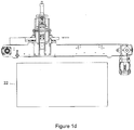
- a leak detector 1 is shown in the figures.
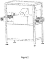
- Figure 2 shows the leak detector 1 mounted to a support frame 2 with a protective housing 22 covering the testing station including a human machine interface 24.
- the other figures show the detail of the testing mechanisms.
- the leak detector 1 has a frame 2 which in use rests on a surface (a warehouse floor or similar) to hold the remainder of the apparatus away from the ground.
- the frame 2 also holds various parts of the remainder of the testing apparatus in position.
- the leak detector 1 has a central conveyor 3 which in the preferred embodiment is of the linear endless belt type, aligned horizontally to convey items from one (open) end or side of the leak detector 1 to the other, opposite (open) side.
- the conveyor 3 can be formed from a number of smaller sub-belts in parallel or a single wide belt.
- a sub-frame 4 is pivotally connected to the frame 2 to one side of the conveyor 3.
- the sub-frame 4 is connected to the frame 2 via a hinge 5 located below the level of the central conveyor 3, the sub-frame 4 extending upwards above and to the side of the conveyor 3.
- a first actuator 6 is mounted on a second sub-frame (not shown) above the conveyor 3.
- the actuator 6 is, in the preferred embodiment, a pneumatic cylinder with linear travel.
- the actuator 6 could be a hydraulic cylinder, or any other suitable type of actuator: linear, rotary or otherwise.
- the active or moving end of the first pneumatic cylinder 6 is connected to the sub-frame 4.
- the body of the first cylinder 6 is connected and held rigidly in relation to the conveyor 3, via the second sub-frame. As the cylinder 6 activates, it pushes the sub-frame 4 so that the sub-frame 4 rotates outwards around the pivot point of the hinge 5 away from the conveyor 3.
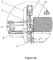
- a gusset manipulation station 10 is connected to the sub-frame 4, the station is connected so that it is just above and to the side of the surface of the conveyor 3.
- the gusset manipulation station 10 has a number of interlocking and moving elements which are activated by actuating cylinders as described below.
- a fixed anvil 8 is connected to the sub-frame 4.
- the fixed anvil 8 has a horizontal upwards-facing anvil striking surface.
- a second linear actuator - flap clamp cylinder 7 - is connected to the sub-frame 4 between the body of the sub-frame 4 and the conveyor 3, above the fixed anvil 8.
- the preferred embodiment of flap clamp cylinder 7 is a pneumatic cylinder, with a moving piston that has a clamp anvil 9 on the lower end, the clamp anvil 9 having a downwards-facing anvil surface complimentary to and aligned with the upwardly-facing surface of the fixed anvil 8.
- the position of the fixed anvil 8 is vertically adjustable, and most preferably horizontally adjustable also (towards and away from the conveyor 3).
- the position of the flap clamp cylinder 7 and in particular the clamp anvil 9 is adjustable in a complimentary manner, either by adjustment of the position of the flap clamp cylinder 7 in it's entirety, or by adjusting the stroke length to suit, so that contact is made at all positions between the flap clamp cylinder 7 and the clamp anvil 9.
- the linear pneumatic flap clamp cylinder 7 could be replaced by any suitable clamping mechanism - for example by a jaw rotating towards the anvil, or a pair of jaws rotating together towards one another, or clamping elements which screw towards one another.
- a pair of mechanical fingers 11a, 11b are located one on each side of the gusset manipulation station 10.
- Each finger 11 is formed from an elongate member extending towards the conveyor 3, the two fingers 11a, 11b angled away from one another (that is, if the lines of the main portion of the bodies of the fingers were extended to convergence, this would occur at a point further away from the conveyor).
- the outer end (away from the conveyor) of each finger 11a and 11b is connected to a pivoting element 12a and 12b that pivots around a substantially vertical axis so that the fingers 11a and 11b rotate in a substantially horizontal plane.
- the inner ends of the fingers 11a and 11b are angled inwards to form hook portions 13a and 13b.
- the pivoting elements 12a and 12b are a pair of meshed, interlocking gear sections or arcs connected to the sub-frame 4, the interlocking portions located between the vertical rotation axes.
- a third linear actuator 14 is connected between a fixed point on the sub-frame 4, and a point on the perimeter of one of the pivoting elements 12a and 12b (i.e. at a distance from the vertical rotation axis of that pivoting element, and between the rotation axes).
- the third linear actuator 14 is aligned to activate horizontally away from the conveyor 3 (in the preferred embodiment, substantially perpendicular to the conveyor 3).
- the third linear actuator 14 activates, it causes the connected one of the pivoting elements 12 to rotate around the vertical rotation axis, which causes the other pivot element to also rotate in the opposite direction due to the meshed gearing. This causes the fingers 11 to rotate inwards, or towards one another.
- the fingers 11 and the hook portions 13 are shaped and sized so that the inner ends arc towards one another and nearly contact each other just to the side and above the edge of the conveyor 3.
- the third linear actuator is a pneumatic cylinder. As before, this could alternatively be a hydraulic cylinder, a rotary screw, or a similar actuating mechanism.
- the fingers and their associated elements form another part of the mechanical gripper formed by flap clamp cylinder 7, clamp anvil 9 and anvil 8.
- the gusset manipulation station 10 is mounted to the sub-frame 4 in such a manner that it can move relative to the sub-frame 4, substantially horizontally towards and away from the sub-frame 4 and conveyor 3.
- a single specimen of the product to be tested i.e. a 20kg block of vacuum packed cheese 16 in the preferred embodiment (or other similar vacuum packed product) is guided onto the belt of the central conveyor 3 at one end, and moves with the belt along and through the leak detector 1 to a point determined by a photo cell (not shown) mounted either on the frame 2, or an equally appropriate position.
- a photo cell (not shown) mounted either on the frame 2, or an equally appropriate position.
- Another similar type of sensor could be used instead of the photo cell (for example a weight sensor placed under the belt at the appropriate position, which activates when the cheese or other product is above the sensor.
- the bagged cheese 16 is placed on the belt so that the flap/seal 17 extends generally horizontally out to one side of the conveyor, on the same side as the sub-frame 2.
- the vertical position of the flap/seal is known, as each individual product item is substantially identical to the others.
- This allows an initial setup/location of items such as the position of the clamp anvil 9 and the fixed anvil 8.
- the block of cheese 16 travels along the conveyor 3 until the photo cell detects that the bagged cheese 16 is positioned and/or aligned opposite the gusset manipulation station 10.
- Linear actuator 23 may then push the bagged cheese 16 towards the gusset manipulation station 10 until the flap 17 is between the clamp anvil 9 and the fixed anvil 8.
- Linear actuator 23 may extend a predetermined distance each time for packages of consistent dimensions or a further sensor may be employed to detect that the flap 17 is correctly located between the anvils.
- the first linear actuator - the flap clamp pneumatic cylinder 7 - is then activated to push the clamp anvil 9 downwards and clamp the flap 17 between the clamp anvil 9 and the fixed anvil 8.
- the second linear actuator - the bag flap stressing pneumatic cylinder 6 - further has an associated sensing means (not shown).
- the bag flap stressing cylinder 6 is then activated to apply a force to the sub-frame 4 and rotate this around the pivot point of the hinge 5 and away from the block of cheese.
- the sensing means will start to measure the displacement of the sub-frame 4, which is indicative of a leak in the plastic packaging.
- the sensing means is an actuator position sensor or mounted position transmitter, most preferably a linear variable differential transformer (LVDT) or similar inductive device.
- LVDT linear variable differential transformer
- the product movement is limited towards sub-frame 4 by a fence fitted to the frame of the testing unit and providing a measurement reference for the displacement of the gripped flap.
- a clamp or holding system can be added to the apparatus to secure it in place during the testing sequence.
- the third linear actuator 14 is activated. This causes the two mechanical fingers 11a, 11b to rotate inwards towards one another. The hook portions 13a, 13b on the ends of the fingers 11a, 11b will be inserted into the folded gussets on each side of the flap 17 of the plastic bag. This action is independent of the action of the bag flap stressing cylinder 6 and the flap clamp cylinder 7.
- the third linear actuator - pneumatic cylinder 14 continues to extend to apply an outwards force to push the fingers 11a and 11b away from the conveyor 3. This causes the hook portions to snag into and manipulate the gusset, and in particular the inside of the plastic gusset seal weld, and a pulling force is applied away from the block of cheese 16. This action will indicate any weakness in the heat sealed area, which will translate to further measurable movement in bag flap stressing cylinder 6 if a leak is present.
- the preferred embodiment of the present invention includes an evaluator or evaluating means which receives signals relating to the sensed movement, and uses these to evaluate whether there is a leak or not.
- the leak evaluation is conducted using the sensed amount of movement from bag flap stressing cylinder 6.
- the amount of movement is compared with an acceptable or predefined profile, which is held in the memory of the evaluator.
- the results of this evaluation tags the product acceptable, or to be rejected.
- An additional suction testing method may also be employed.
- a linear actuator in the form of pneumatic ram 25 may lower suction cup 26 down onto the top surface of the block of cheese 16. Suction may then be applied to the suction cup 26 and the pneumatic ram may be retracted with a set force. The distance travelled up by the pneumatic ram may be measured to provide an additional assessment as to whether the bag is leaking or not.
- a suction testing method may be used before, after or during the gusset flap testing method described above.
- the method (and associated apparatus) as outlined above is advantageous as outlined below: Pulling the flap/seal 17 is an effective method of detecting large leaks, and pulling in this manner puts lower stress on the packaging.
- a mechanical gripper provides a robust and reliable means of engagement with the packaging, and does not require a flat surface for use.
- the apparatus can therefore provide a useful alternative to an apparatus or method that uses only a suction cup.
- gusset manipulation also acts as a useful comparator to the physical manipulation.
Landscapes
- Physics & Mathematics (AREA)
- General Physics & Mathematics (AREA)
- Examining Or Testing Airtightness (AREA)
Claims (15)
- Dichtheitsprüfvorrichtung (1) zum Prüfen der Unversehrtheit der Dichtung in der Verpackung eines vakuumverpackten Produkts (16), umfassend:einen mechanischen Greifer (8, 9) zum Greifen eines Abschnitts der Verpackung (17);ein erstes Betätigungselement (6), das dazu ausgelegt ist, den gegriffenen Abschnitt von dem Produkt wegzuziehen;einen Sensor zum Überwachen der Bewegung des gegriffenen Abschnitts relativ zum vakuumverpackten Produkt (16), und;eine Auswerteeinrichtung, die die erfasste Bewegung des gegriffenen Abschnitts mit einem zulässigen Profil vergleicht und das Produkt basierend auf dem Vergleich annimmt oder ablehnt.
- Dichtheitsprüfvorrichtung nach Anspruch 1, wobei der mechanische Greifer eine Klemme ist, die geeignet ist, jede Seite einer sich vom Hauptkörper der Verpackung erstreckenden Klappe zu schließen und zu greifen.
- Dichtheitsprüfvorrichtung nach Anspruch 1 oder Anspruch 2, wobei der Sensor ein Betätigungselement-Positionssensor oder ein angebauter Positionsgeber ist.
- Dichtheitsprüfvorrichtung nach einem der Ansprüche 1 bis 3, wobei die Dichtheitsprüfvorrichtung ferner einen Rahmen aufweist, auf dem das vakuumverpackte Produkt bei Gebrauch aufliegt, der Greifer auf einem mit dem Rahmen schwenkbar verbundenen Hilfsrahmen montiert ist, das erste Betätigungselement auf den Hilfsrahmen wirkt, um den geschlossenen Greifer vom Produkt weg zu ziehen.
- Dichtheitsprüfvorrichtung nach einem der Ansprüche 1 bis 4, wobei die Dichtheitsprüfvorrichtung ferner einen Seitenfaltenmanipulator aufweist, der mindestens einen Finger umfasst, der in den Seitenfaltenbereich eingeführt wird, um eine Seitenfalte in der mit der Klappe verbundenen Verpackung aufzugreifen.
- Dichtheitsprüfvorrichtung nach Anspruch 5, wobei der Seitenfaltenmanipulator ein Paar von Fingern ist, die in und aus dem Eingriff mit der Seitenfalte schwenken, wobei jeder Finger einen Hakenabschnitt am inneren Ende aufweist, der beim Eingreifen der Finger in die Seite der Seitenfalte eingeführt wird.
- Dichtheitsprüfmaschine nach Anspruch 4 bis 6, wobei ein endloses lineares Band auf dem Rahmen montiert ist, das Paket auf dem Band in Betrieb aufliegt und von diesem transportiert wird und das Band das Paket von einer Seite des Rahmens zur anderen, am Hilfsrahmen und Seitenfaltenmanipulator vorbei, transportiert.
- Dichtheitsprüfmaschine nach einem der Ansprüche 1 bis 7, wobei die Auswerteeinrichtung Eingaben vom Sensor empfängt und die Unversehrtheit der Dichtung durch Vergleichen der tatsächlichen Verschiebung im Zeitverlauf mit einem vordefinierten zulässigen Profil der Verschiebung und Zeit beurteilt.
- Dichtheitsprüfmaschine nach Anspruch 8, wobei das zulässige Profil aus einer absoluten Verschiebung besteht.
- Dichtheitsprüfmaschine nach Anspruch 8, wobei das zulässige Profil aus einer Verschiebung über ein Zeitintervall besteht.
- Verfahren zum Prüfen der Unversehrtheit der Dichtung bei der Verpackung eines vakuumverpackten Produkts, umfassend die Schritte:mechanisches Greifen eines Teils der Verpackung;Aufbringen einer Kraft, um den gegriffenen Abschnitt in eine Richtung vom Produkt weg zu ziehen;Überwachen der Bewegung des gegriffenen Abschnitts relativ zum vakuumverpackten Produkt;Vergleichen der überwachten Bewegung mit einem zulässigen Profil; undAnnahme oder Ablehnung des Produkts basierend auf dem Vergleich.
- Verfahren zum Prüfen der Unversehrtheit der Dichtung nach Anspruch 11, wobei beim Schritt des Vergleichens der überwachten Bewegung mit einem zulässigen Profil die tatsächliche Verschiebung über die Zeit mit einem vordefinierten zulässigen Profil der Verschiebung und Zeit verglichen wird.
- Verfahren zum Prüfen der Unversehrtheit der Dichtung nach Anspruch 11 oder Anspruch 12, wobei beim Schritt des Vergleichens der überwachten Bewegung mit einem zulässigen Profil das zulässige Profil aus einer absoluten Verschiebung besteht.
- Verfahren zum Prüfen Unversehrtheit der Dichtung nach Anspruch 11 oder Anspruch 12, wobei beim Schritt des Vergleichens der überwachten Bewegung mit einem zulässigen Profil das zulässige Profil aus einer Verschiebung über ein Zeitintervall besteht.
- Verfahren zum Prüfen der Unversehrtheit der Dichtung nach einem der Ansprüche 11 bis 14, wobei beim Schritt des mechanischen Greifens eines Abschnitts der Verpackung mechanische Finger in den Seitenfaltenbereich eingeführt werden, um eine Seitenfalte in der mit der Klappe verbundenen Verpackung handzuhaben.
Applications Claiming Priority (2)
| Application Number | Priority Date | Filing Date | Title |
|---|---|---|---|
| NZ61832913 | 2013-11-28 | ||
| PCT/NZ2014/000236 WO2015080601A1 (en) | 2013-11-28 | 2014-11-27 | A leak detector and package integrity testing mechanism and testing method for vacuum-sealed packages |
Publications (2)
| Publication Number | Publication Date |
|---|---|
| EP3074745A1 EP3074745A1 (de) | 2016-10-05 |
| EP3074745B1 true EP3074745B1 (de) | 2019-11-13 |
Family
ID=52350263
Family Applications (1)
| Application Number | Title | Priority Date | Filing Date |
|---|---|---|---|
| EP14827561.3A Not-in-force EP3074745B1 (de) | 2013-11-28 | 2014-11-27 | Leckdetektor und mechanismus zur prüfung der verpackungsunversehrt sowie testverfahren zur prüfung von vakuumpackungen |
Country Status (4)
| Country | Link |
|---|---|
| US (1) | US20170160164A1 (de) |
| EP (1) | EP3074745B1 (de) |
| AU (2) | AU2014355230A1 (de) |
| WO (1) | WO2015080601A1 (de) |
Families Citing this family (5)
| Publication number | Priority date | Publication date | Assignee | Title |
|---|---|---|---|---|
| DE102018202451B4 (de) * | 2018-02-19 | 2023-01-12 | Vitesco Technologies Germany Gmbh | Pouchzellen-Dichtheitsmessanordnung und Verfahren zur Messung einer Dichtheit von Pouchzellen |
| EP3839470B1 (de) | 2019-12-16 | 2025-01-15 | Elopak ASA | Verfahren und vorrichtung zum prüfen von pappebasierten behältern |
| CN115090558B (zh) * | 2022-07-30 | 2023-03-03 | 东莞市群立自动化科技有限公司 | 一种锂电池漏液检测设备及检测方法 |
| CN116793598B (zh) * | 2023-07-19 | 2024-05-03 | 重庆南瑞博瑞变压器有限公司 | 一种油浸式变压器保压密封检测装置 |
| CN120369235A (zh) * | 2025-06-26 | 2025-07-25 | 崇义县勤慧农业发展有限公司 | 一种袋装真空食品气密性自动检测装置 |
Family Cites Families (10)
| Publication number | Priority date | Publication date | Assignee | Title |
|---|---|---|---|---|
| US2374140A (en) * | 1943-07-09 | 1945-04-17 | Robert N Shoner | Seal leakage detector for canned goods |
| US3744210A (en) | 1971-06-28 | 1973-07-10 | Standard Packaging Corp | Packaging machine and method |
| US3877302A (en) * | 1973-12-06 | 1975-04-15 | Us Army | Method for determining tightness of film shrunk over a container or an assembly of containers |
| US3998091A (en) * | 1975-06-23 | 1976-12-21 | Paquette Michael W | Test apparatus for determining quality of packaging for vacuum packaged products |
| US4517827A (en) | 1983-03-24 | 1985-05-21 | General Foods Incorporated | Apparatus and method for testing for leakages in hermetically-sealed packages |
| GB9205011D0 (en) | 1992-03-07 | 1992-04-22 | Fenlon Christopher | Sealed package integrity testing machine |
| DE19622588C1 (de) * | 1996-06-05 | 1998-01-02 | Koeger Heinz | Vorrichtung zum Feststellen der Dichtheit von gefüllten Behältern |
| EP1050469B1 (de) * | 1999-04-07 | 2003-03-19 | Ishida Co., Ltd. | System zum automatischen Prüfen von Verpackungen |
| US20100122570A1 (en) | 2008-11-14 | 2010-05-20 | Kraft Foods Global Brands Llc | Method and apparatus for detecting sealing of food packages |
| DE202011107446U1 (de) * | 2011-11-04 | 2013-02-06 | Eckhard Polman | Vorrichtung zur vakuumbasierten Dichtheitsprüfung von in einem kontinuierlichen Verpackungsstrom zugeführten Verpackungen |
-
2014
- 2014-11-27 WO PCT/NZ2014/000236 patent/WO2015080601A1/en not_active Ceased
- 2014-11-27 EP EP14827561.3A patent/EP3074745B1/de not_active Not-in-force
- 2014-11-27 US US15/039,376 patent/US20170160164A1/en not_active Abandoned
- 2014-11-27 AU AU2014355230A patent/AU2014355230A1/en not_active Abandoned
-
2019
- 2019-08-02 AU AU2019210663A patent/AU2019210663A1/en not_active Abandoned
Non-Patent Citations (1)
| Title |
|---|
| None * |
Also Published As
| Publication number | Publication date |
|---|---|
| WO2015080601A1 (en) | 2015-06-04 |
| AU2014355230A1 (en) | 2016-07-07 |
| EP3074745A1 (de) | 2016-10-05 |
| AU2019210663A1 (en) | 2019-08-22 |
| US20170160164A1 (en) | 2017-06-08 |
Similar Documents
| Publication | Publication Date | Title |
|---|---|---|
| AU2019210663A1 (en) | A leak detector and package integrity testing mechanism and testing method for vacuum-sealed packages | |
| US5111684A (en) | Method and apparatus for leak testing packages | |
| EP3405398B1 (de) | Verfahren zur dichtigkeitsprüfung einer fertiggestellten verpackung | |
| US3591944A (en) | Method and apparatus for detection of leaks in seals of packages | |
| ES2883262T3 (es) | Procedimiento y dispositivo para la comprobación de objetos suministrados de manera continua | |
| AU2009251801A1 (en) | Method for positioning a loaded bag in a vacuum chamber | |
| JP2012007931A (ja) | 袋包装商品のシールチェック装置及びシールチェック方法 | |
| US3708949A (en) | Method and apparatus for detection of leaks in seals of packages | |
| US5507177A (en) | Method and apparatus for testing the tightness of foil bags | |
| JPH0658281B2 (ja) | 充填物を充填した密閉容器のシ−ル性を検査する方法と装置 | |
| NL9100867A (nl) | Werkwijze en inrichting voor het op lekkage onderzoeken van een gevulde en gesloten flexibele verpakking. | |
| JP6348294B2 (ja) | チューブ容器検査装置 | |
| US20240077394A1 (en) | Apparatus, plant and method for inspecting flexible packages | |
| JP4072455B2 (ja) | 包装体シール部の漏洩検査方法及び装置 | |
| AU2009233618A1 (en) | Method and apparatus for detecting sealing of food packages | |
| US9056691B2 (en) | Bag deflation devices and methods for deflating bags | |
| CN115465501B (zh) | 一种速冻食品用包装装置及其包装方法 | |
| JP2005009931A (ja) | シール不良検査装置 | |
| JP4008869B2 (ja) | 包装体シール部の漏洩検査方法及び装置 | |
| WO2002073151A1 (en) | Production line leak testing | |
| JP2000121487A (ja) | 空缶等の漏洩検査方法 | |
| JP7010912B2 (ja) | 包装体の検査システム | |
| JP2000318716A (ja) | 袋詰機における袋の処理方法及びその装置 | |
| CN113237606A (zh) | 辣条包装漏气漏油检测设备 | |
| JP2015182795A (ja) | 真空引きされた包装体の真空状態検査方法および装置 |
Legal Events
| Date | Code | Title | Description |
|---|---|---|---|
| PUAI | Public reference made under article 153(3) epc to a published international application that has entered the european phase |
Free format text: ORIGINAL CODE: 0009012 |
|
| 17P | Request for examination filed |
Effective date: 20160620 |
|
| AK | Designated contracting states |
Kind code of ref document: A1 Designated state(s): AL AT BE BG CH CY CZ DE DK EE ES FI FR GB GR HR HU IE IS IT LI LT LU LV MC MK MT NL NO PL PT RO RS SE SI SK SM TR |
|
| AX | Request for extension of the european patent |
Extension state: BA ME |
|
| DAX | Request for extension of the european patent (deleted) | ||
| GRAP | Despatch of communication of intention to grant a patent |
Free format text: ORIGINAL CODE: EPIDOSNIGR1 |
|
| STAA | Information on the status of an ep patent application or granted ep patent |
Free format text: STATUS: GRANT OF PATENT IS INTENDED |
|
| INTG | Intention to grant announced |
Effective date: 20190607 |
|
| GRAS | Grant fee paid |
Free format text: ORIGINAL CODE: EPIDOSNIGR3 |
|
| GRAA | (expected) grant |
Free format text: ORIGINAL CODE: 0009210 |
|
| STAA | Information on the status of an ep patent application or granted ep patent |
Free format text: STATUS: THE PATENT HAS BEEN GRANTED |
|
| AK | Designated contracting states |
Kind code of ref document: B1 Designated state(s): AL AT BE BG CH CY CZ DE DK EE ES FI FR GB GR HR HU IE IS IT LI LT LU LV MC MK MT NL NO PL PT RO RS SE SI SK SM TR |
|
| REG | Reference to a national code |
Ref country code: CH Ref legal event code: EP Ref country code: AT Ref legal event code: REF Ref document number: 1202167 Country of ref document: AT Kind code of ref document: T Effective date: 20191115 |
|
| REG | Reference to a national code |
Ref country code: DE Ref legal event code: R096 Ref document number: 602014056878 Country of ref document: DE |
|
| REG | Reference to a national code |
Ref country code: IE Ref legal event code: FG4D |
|
| REG | Reference to a national code |
Ref country code: NL Ref legal event code: MP Effective date: 20191113 |
|
| REG | Reference to a national code |
Ref country code: LT Ref legal event code: MG4D |
|
| PG25 | Lapsed in a contracting state [announced via postgrant information from national office to epo] |
Ref country code: PL Free format text: LAPSE BECAUSE OF FAILURE TO SUBMIT A TRANSLATION OF THE DESCRIPTION OR TO PAY THE FEE WITHIN THE PRESCRIBED TIME-LIMIT Effective date: 20191113 Ref country code: LT Free format text: LAPSE BECAUSE OF FAILURE TO SUBMIT A TRANSLATION OF THE DESCRIPTION OR TO PAY THE FEE WITHIN THE PRESCRIBED TIME-LIMIT Effective date: 20191113 Ref country code: SE Free format text: LAPSE BECAUSE OF FAILURE TO SUBMIT A TRANSLATION OF THE DESCRIPTION OR TO PAY THE FEE WITHIN THE PRESCRIBED TIME-LIMIT Effective date: 20191113 Ref country code: NL Free format text: LAPSE BECAUSE OF FAILURE TO SUBMIT A TRANSLATION OF THE DESCRIPTION OR TO PAY THE FEE WITHIN THE PRESCRIBED TIME-LIMIT Effective date: 20191113 Ref country code: BG Free format text: LAPSE BECAUSE OF FAILURE TO SUBMIT A TRANSLATION OF THE DESCRIPTION OR TO PAY THE FEE WITHIN THE PRESCRIBED TIME-LIMIT Effective date: 20200213 Ref country code: FI Free format text: LAPSE BECAUSE OF FAILURE TO SUBMIT A TRANSLATION OF THE DESCRIPTION OR TO PAY THE FEE WITHIN THE PRESCRIBED TIME-LIMIT Effective date: 20191113 Ref country code: LV Free format text: LAPSE BECAUSE OF FAILURE TO SUBMIT A TRANSLATION OF THE DESCRIPTION OR TO PAY THE FEE WITHIN THE PRESCRIBED TIME-LIMIT Effective date: 20191113 Ref country code: GR Free format text: LAPSE BECAUSE OF FAILURE TO SUBMIT A TRANSLATION OF THE DESCRIPTION OR TO PAY THE FEE WITHIN THE PRESCRIBED TIME-LIMIT Effective date: 20200214 Ref country code: PT Free format text: LAPSE BECAUSE OF FAILURE TO SUBMIT A TRANSLATION OF THE DESCRIPTION OR TO PAY THE FEE WITHIN THE PRESCRIBED TIME-LIMIT Effective date: 20200313 Ref country code: NO Free format text: LAPSE BECAUSE OF FAILURE TO SUBMIT A TRANSLATION OF THE DESCRIPTION OR TO PAY THE FEE WITHIN THE PRESCRIBED TIME-LIMIT Effective date: 20200213 |
|
| PG25 | Lapsed in a contracting state [announced via postgrant information from national office to epo] |
Ref country code: RS Free format text: LAPSE BECAUSE OF FAILURE TO SUBMIT A TRANSLATION OF THE DESCRIPTION OR TO PAY THE FEE WITHIN THE PRESCRIBED TIME-LIMIT Effective date: 20191113 Ref country code: HR Free format text: LAPSE BECAUSE OF FAILURE TO SUBMIT A TRANSLATION OF THE DESCRIPTION OR TO PAY THE FEE WITHIN THE PRESCRIBED TIME-LIMIT Effective date: 20191113 Ref country code: IS Free format text: LAPSE BECAUSE OF FAILURE TO SUBMIT A TRANSLATION OF THE DESCRIPTION OR TO PAY THE FEE WITHIN THE PRESCRIBED TIME-LIMIT Effective date: 20200313 |
|
| REG | Reference to a national code |
Ref country code: DE Ref legal event code: R119 Ref document number: 602014056878 Country of ref document: DE |
|
| PG25 | Lapsed in a contracting state [announced via postgrant information from national office to epo] |
Ref country code: AL Free format text: LAPSE BECAUSE OF FAILURE TO SUBMIT A TRANSLATION OF THE DESCRIPTION OR TO PAY THE FEE WITHIN THE PRESCRIBED TIME-LIMIT Effective date: 20191113 |
|
| REG | Reference to a national code |
Ref country code: CH Ref legal event code: PL |
|
| PG25 | Lapsed in a contracting state [announced via postgrant information from national office to epo] |
Ref country code: LU Free format text: LAPSE BECAUSE OF NON-PAYMENT OF DUE FEES Effective date: 20191127 Ref country code: CZ Free format text: LAPSE BECAUSE OF FAILURE TO SUBMIT A TRANSLATION OF THE DESCRIPTION OR TO PAY THE FEE WITHIN THE PRESCRIBED TIME-LIMIT Effective date: 20191113 Ref country code: LI Free format text: LAPSE BECAUSE OF NON-PAYMENT OF DUE FEES Effective date: 20191130 Ref country code: RO Free format text: LAPSE BECAUSE OF FAILURE TO SUBMIT A TRANSLATION OF THE DESCRIPTION OR TO PAY THE FEE WITHIN THE PRESCRIBED TIME-LIMIT Effective date: 20191113 Ref country code: ES Free format text: LAPSE BECAUSE OF FAILURE TO SUBMIT A TRANSLATION OF THE DESCRIPTION OR TO PAY THE FEE WITHIN THE PRESCRIBED TIME-LIMIT Effective date: 20191113 Ref country code: EE Free format text: LAPSE BECAUSE OF FAILURE TO SUBMIT A TRANSLATION OF THE DESCRIPTION OR TO PAY THE FEE WITHIN THE PRESCRIBED TIME-LIMIT Effective date: 20191113 Ref country code: CH Free format text: LAPSE BECAUSE OF NON-PAYMENT OF DUE FEES Effective date: 20191130 Ref country code: DK Free format text: LAPSE BECAUSE OF FAILURE TO SUBMIT A TRANSLATION OF THE DESCRIPTION OR TO PAY THE FEE WITHIN THE PRESCRIBED TIME-LIMIT Effective date: 20191113 |
|
| REG | Reference to a national code |
Ref country code: AT Ref legal event code: MK05 Ref document number: 1202167 Country of ref document: AT Kind code of ref document: T Effective date: 20191113 |
|
| REG | Reference to a national code |
Ref country code: BE Ref legal event code: MM Effective date: 20191130 |
|
| PG25 | Lapsed in a contracting state [announced via postgrant information from national office to epo] |
Ref country code: SK Free format text: LAPSE BECAUSE OF FAILURE TO SUBMIT A TRANSLATION OF THE DESCRIPTION OR TO PAY THE FEE WITHIN THE PRESCRIBED TIME-LIMIT Effective date: 20191113 Ref country code: MC Free format text: LAPSE BECAUSE OF FAILURE TO SUBMIT A TRANSLATION OF THE DESCRIPTION OR TO PAY THE FEE WITHIN THE PRESCRIBED TIME-LIMIT Effective date: 20191113 Ref country code: SM Free format text: LAPSE BECAUSE OF FAILURE TO SUBMIT A TRANSLATION OF THE DESCRIPTION OR TO PAY THE FEE WITHIN THE PRESCRIBED TIME-LIMIT Effective date: 20191113 |
|
| PLBE | No opposition filed within time limit |
Free format text: ORIGINAL CODE: 0009261 |
|
| STAA | Information on the status of an ep patent application or granted ep patent |
Free format text: STATUS: NO OPPOSITION FILED WITHIN TIME LIMIT |
|
| 26N | No opposition filed |
Effective date: 20200814 |
|
| GBPC | Gb: european patent ceased through non-payment of renewal fee |
Effective date: 20200213 |
|
| PG25 | Lapsed in a contracting state [announced via postgrant information from national office to epo] |
Ref country code: IE Free format text: LAPSE BECAUSE OF NON-PAYMENT OF DUE FEES Effective date: 20191127 Ref country code: FR Free format text: LAPSE BECAUSE OF NON-PAYMENT OF DUE FEES Effective date: 20200113 Ref country code: DE Free format text: LAPSE BECAUSE OF NON-PAYMENT OF DUE FEES Effective date: 20200603 |
|
| PG25 | Lapsed in a contracting state [announced via postgrant information from national office to epo] |
Ref country code: AT Free format text: LAPSE BECAUSE OF FAILURE TO SUBMIT A TRANSLATION OF THE DESCRIPTION OR TO PAY THE FEE WITHIN THE PRESCRIBED TIME-LIMIT Effective date: 20191113 Ref country code: SI Free format text: LAPSE BECAUSE OF FAILURE TO SUBMIT A TRANSLATION OF THE DESCRIPTION OR TO PAY THE FEE WITHIN THE PRESCRIBED TIME-LIMIT Effective date: 20191113 Ref country code: BE Free format text: LAPSE BECAUSE OF NON-PAYMENT OF DUE FEES Effective date: 20191130 |
|
| PG25 | Lapsed in a contracting state [announced via postgrant information from national office to epo] |
Ref country code: IT Free format text: LAPSE BECAUSE OF FAILURE TO SUBMIT A TRANSLATION OF THE DESCRIPTION OR TO PAY THE FEE WITHIN THE PRESCRIBED TIME-LIMIT Effective date: 20191113 Ref country code: GB Free format text: LAPSE BECAUSE OF NON-PAYMENT OF DUE FEES Effective date: 20200213 |
|
| PG25 | Lapsed in a contracting state [announced via postgrant information from national office to epo] |
Ref country code: CY Free format text: LAPSE BECAUSE OF FAILURE TO SUBMIT A TRANSLATION OF THE DESCRIPTION OR TO PAY THE FEE WITHIN THE PRESCRIBED TIME-LIMIT Effective date: 20191113 |
|
| PG25 | Lapsed in a contracting state [announced via postgrant information from national office to epo] |
Ref country code: MT Free format text: LAPSE BECAUSE OF FAILURE TO SUBMIT A TRANSLATION OF THE DESCRIPTION OR TO PAY THE FEE WITHIN THE PRESCRIBED TIME-LIMIT Effective date: 20191113 Ref country code: HU Free format text: LAPSE BECAUSE OF FAILURE TO SUBMIT A TRANSLATION OF THE DESCRIPTION OR TO PAY THE FEE WITHIN THE PRESCRIBED TIME-LIMIT; INVALID AB INITIO Effective date: 20141127 |
|
| PG25 | Lapsed in a contracting state [announced via postgrant information from national office to epo] |
Ref country code: TR Free format text: LAPSE BECAUSE OF FAILURE TO SUBMIT A TRANSLATION OF THE DESCRIPTION OR TO PAY THE FEE WITHIN THE PRESCRIBED TIME-LIMIT Effective date: 20191113 |
|
| PG25 | Lapsed in a contracting state [announced via postgrant information from national office to epo] |
Ref country code: MK Free format text: LAPSE BECAUSE OF FAILURE TO SUBMIT A TRANSLATION OF THE DESCRIPTION OR TO PAY THE FEE WITHIN THE PRESCRIBED TIME-LIMIT Effective date: 20191113 |