EP3074665B1 - Antriebsstrangvorrichtung für ein kraftfahrzeug - Google Patents
Antriebsstrangvorrichtung für ein kraftfahrzeug Download PDFInfo
- Publication number
- EP3074665B1 EP3074665B1 EP14809292.7A EP14809292A EP3074665B1 EP 3074665 B1 EP3074665 B1 EP 3074665B1 EP 14809292 A EP14809292 A EP 14809292A EP 3074665 B1 EP3074665 B1 EP 3074665B1
- Authority
- EP
- European Patent Office
- Prior art keywords
- component
- cast
- sealing
- sealing element
- drive train
- Prior art date
- Legal status (The legal status is an assumption and is not a legal conclusion. Google has not performed a legal analysis and makes no representation as to the accuracy of the status listed.)
- Active
Links
Images


Classifications
-
- F—MECHANICAL ENGINEERING; LIGHTING; HEATING; WEAPONS; BLASTING
- F16—ENGINEERING ELEMENTS AND UNITS; GENERAL MEASURES FOR PRODUCING AND MAINTAINING EFFECTIVE FUNCTIONING OF MACHINES OR INSTALLATIONS; THERMAL INSULATION IN GENERAL
- F16H—GEARING
- F16H41/00—Rotary fluid gearing of the hydrokinetic type
- F16H41/24—Details
-
- F—MECHANICAL ENGINEERING; LIGHTING; HEATING; WEAPONS; BLASTING
- F16—ENGINEERING ELEMENTS AND UNITS; GENERAL MEASURES FOR PRODUCING AND MAINTAINING EFFECTIVE FUNCTIONING OF MACHINES OR INSTALLATIONS; THERMAL INSULATION IN GENERAL
- F16J—PISTONS; CYLINDERS; SEALINGS
- F16J15/00—Sealings
- F16J15/02—Sealings between relatively-stationary surfaces
- F16J15/021—Sealings between relatively-stationary surfaces with elastic packing
- F16J15/022—Sealings between relatively-stationary surfaces with elastic packing characterised by structure or material
-
- F—MECHANICAL ENGINEERING; LIGHTING; HEATING; WEAPONS; BLASTING
- F16—ENGINEERING ELEMENTS AND UNITS; GENERAL MEASURES FOR PRODUCING AND MAINTAINING EFFECTIVE FUNCTIONING OF MACHINES OR INSTALLATIONS; THERMAL INSULATION IN GENERAL
- F16H—GEARING
- F16H41/00—Rotary fluid gearing of the hydrokinetic type
- F16H41/24—Details
- F16H2041/243—Connections between pump shell and cover shell of the turbine
Definitions
- the invention relates to a drive train device for a motor vehicle.
- the JP2009168116A a powertrain device for a motor vehicle is known, comprising at least one component provided for transmitting a torque and at least one element partially cast into the component, which is provided for transmitting the torque, wherein the component and the cast-in element consist of different materials, wherein the component with at least one further provided for transmitting a torque component via the cast-in element is connected torque transmitting indirectly, such that the torque can be transmitted only via the cast-in element between the components.
- the invention is in particular the object of economically producing a drive train device in lightweight construction. This object is achieved by an inventive embodiment of a drive train device according to claim 1. Further developments of the invention will become apparent from the dependent claims.
- the invention relates to a drive train device for a motor vehicle, comprising at least one component provided for transmitting a torque and at least one element partially cast into the component, which is provided for transmitting the torque, wherein the component and the cast-in element consist of different materials.
- the drive train device has a sealing unit which is provided to seal a joint between the component and the cast-in element.
- the component with at least one further provided for transmitting a torque component indirectly via the cast-in element can be connected to transmit torque, whereby the torque can be transmitted via the cast-in element between the components.
- the component comprising the cast-in element can be formed from a first material and the further component from a second material differing from the first material, whereby a production of the drive train device, in particular due to a choice of a connection method for the torque-transmitting connection of the components, can be made more flexible.
- the material of the cast-in element can be adapted to the material of the further component with regard to a connection with the further component, whereby the connection between the components can be carried out in a particularly reliable, robust and cost-effective manner, without restricting the choice of the material of the components having to accept.
- one of the components can be formed from a particularly lightweight material compared to the other component, whereby the drive train device is particularly lightweight in design and fuel consumption of the drive train device having motor vehicle can be reduced.
- a seat of the cast-in element in the component can be adversely affected in terms of tightness, whereby leakage through the joint can occur.
- sealing unit By provided for sealing the connection point at which the component and the cast-in element are positively connected by a casting, provided sealing unit, a possible leakage through the joint can be prevented. It can be a tightness of the joint and thus the torque-transmitting connection between the components are ensured, whereby leakage in the drive train device can be reliably prevented.
- the powertrain device can thereby be produced particularly economically in lightweight construction, without reducing a quality of the drive train device.
- a “cast-in element” is to be understood, in particular, as an element that is positively connected to this component by a casting process, in particular an injection-molding process, of the cast component.
- the cast-in element is advantageously formed annular, whereby the connection between the component and the cast-in element can be made more reliable.
- partially cast into the component is to be understood in particular that the cast-in element protrudes at least on one side from the material of the component.
- a “connection point” is to be understood, in particular, as a point at which the component and the element cast into the component are positively connected with one another due to a casting operation of the component.
- the material of the component having the cast-in element and the material of the cast-in element differ at least in a thermal expansion coefficient.
- a “sealing unit” is to be understood in particular a unit which is intended to a To provide sealing effect for sealing the joint, wherein the sealing effect by at least one sealing element, by a special arrangement of at least one component and / or element of the drive train device, by a special shaping of at least one component and / or element of the drive train device, by a special material of at least one component and / or elements of the powertrain device and / or may be provided by a special encapsulation of the cast-in element.
- By “provided” is to be understood in particular to be specially designed, designed, equipped and / or arranged.
- the component having the cast-in element consists at least essentially of a material designed as light metal and the cast-in element consists at least essentially of a predominantly iron-containing material, whereby the weight of the drive train device can be reduced.
- a "light metal” is to be understood in particular as meaning a metal and / or an alloy whose density is below 5 g / cm 3 , in particular aluminum.
- substantially is meant in particular at least 60%, advantageously at least 80%, and particularly advantageously at least 90%.
- the drive train device has at least one further component provided for transmitting the torque, which at least partially encloses an inner space together with the other component, wherein the sealing unit is provided to seal the connection point and the inner space against each other.
- the further component advantageously consists at least essentially of a predominantly iron-containing material.
- the cast-in element is designed as a connecting element, which is materially connected to produce a torque-transmitting connection between the components with the other component.
- the cohesive connection makes it possible to dispense with a complex and expensive connection method, such as, in particular, screws, rivets and welded rivets, as a result of which the cost of the drive train device in lightweight construction can be reduced.
- at least two components of the drive train device wherein one of the components consists of the material formed as light metal, are connected to each other in a particularly cost-effective torque-transmitting manner, whereby a drive train device in lightweight construction can be produced economically.
- the cast-in element and the further component are welded together and / or soldered.
- the sealing unit is provided to provide a sealing force for sealing the joint due to an at least partially elastic deformation and / or due to an adhesion, whereby the joint can be sealed particularly reliable.
- the sealing unit which is intended to provide a sealing force for sealing the joint due to an at least partially elastic deformation, preferably has at least one at least partially elastic sealing element, which provides its sealing effect in particular after its at least partially elastic deformation.
- the at least partially elastic sealing element is advantageously designed as a sealing disk, as a sealing ring or the like.
- the at least partially elastic sealing element consists at least partly of rubber, rubber, polyethylene, polytetrafluoroethylene or the like.
- the at least partially elastic sealing element may also consist at least partially of metal, such as copper.
- the sealing unit which is provided to provide the sealing force for sealing the joint due to the at least partially elastic deformation, is formed integrally with one of the components or the cast-in element.
- the sealing unit which is intended to provide a sealing force for sealing the connection point due to adhesion, preferably has at least one adhesive sealing element which provides its sealing effect, in particular after its hardening.
- the adhesive sealing member is advantageously formed as a silicone rubber, a silicone elastomer, a synthetic polymer or the like. Furthermore, it is basically conceivable to realize the sealing unit by targeted casting of the component at least in the region of the connection point.
- the sealing unit has at least one sealing element, which is arranged sealingly between the two components, whereby a particularly high sealing force can be provided.
- a “sealing element which is sealingly arranged between the two components” should in particular be understood as meaning a sealing element which makes a sealing contact with both components.
- the sealing unit has at least one sealing element, which is arranged sealingly between at least one of the components and the cast-in element, whereby an assembly of the two components can be simplified.
- a sealing element sealingly between at least one of the components and the embedded element is arranged "should be understood in particular a sealing element, the at least one of the components and the cast-in element sealingly contacted.
- At least one of the components has at least one sealing element receptacle which at least partially accommodates the at least one sealing element, whereby assembly of the sealing element can be simplified.
- At least one of the components has a movement inhibition for the sealing element, which is intended to at least complicate a movement of the sealing element in the sealing element receiving, whereby a secure fit of the sealing element can be provided.
- the movement inhibition is advantageously designed as a groove in which the sealing element is arranged within the sealing element receiving.
- the movement inhibition can also be formed by a roughened or textured surface in the sealing element receiving.
- a "roughened surface” is to be understood as meaning in particular a surface which has a macroscopic roughness with an average roughness height of 0.05 to 0.2 millimeters.
- a “structured surface” is to be understood in particular as meaning a surface which has a macroscopic roughness with an average roughness height of 0.1 to 1.5 millimeters.
- the structured surface preferably has recognizable elevations and depressions, such as, for example, grooves, webs, knobs or the like, with the naked eye.
- the cast-in element is provided, at least partially form the sealing unit due to its shape, whereby the junction can be sealed particularly compact and easy to install.
- a part of the cast-in element, which is completely surrounded by the material of the molded component has a shape which is provided for forming the sealing unit, whereby the connection point can be invisibly sealed from the outside.
- the completely surrounded by the material of the molded component Part of the cast-in element shaped in the manner that the cast component is shrunk onto the cast-in element during or after cooling of the material of the cast component after the casting process.
- a "cast component" is to be understood in particular as the component into which the cast-in element is partially cast.
- the cast-in element has at least one surrounding by the material of the cast component undercut, which is intended to form the sealing unit at least partially.
- the part of the cast-in element, which is completely surrounded by the material of the molded component be used to provide the sealing effect, which can be dispensed with separate sealing elements.
- At least one of the components at least partially forms a torque converter housing, whereby a torque converter in lightweight construction can be produced economically.
- a torque converter housing should in particular be understood to mean a housing that at least partially surrounds and / or receives at least one component of the torque converter.
- one of the components forms an impeller and the other component at least partially forms an outer disk carrier, whereby a cost-effective torque converter can be provided with a torque converter lockup clutch in lightweight construction.
- a manufacturing method for producing a drive train device of a motor vehicle in particular a drive train device according to the invention, proposed, in which a connection point between a provided for transmitting a torque component, consisting of a first material, and at least one partially cast in the component and for transmitting the torque provided element, consisting of a second material different from the first material, is sealed, before another for transmitting the torque provided component is connected torque-transmitting with the cast-in element.
- FIG. 1 shows a drive train device for a motor vehicle, not shown in detail, which is provided for a drive train of the motor vehicle.
- the drive train device has an unspecified automatic transmission and a hydraulic torque converter 20a with a lockup clutch.
- the Torque converter 20a in this case has an impeller, a turbine wheel and a stator.
- the converter lockup clutch has an outer disk carrier, which is non-rotatably connected to the impeller, and an inner disk carrier, which is non-rotatably connected to the turbine wheel on.
- the drive train device further comprises a first provided for transmitting a torque component 10a and a second provided for transmitting a torque component 14a, which are connected to each other to transmit torque.
- the drive train device For receiving the first component 10a and the second component 14a, the drive train device has a housing not shown in detail, within which the first component 10a and the second component 14a are arranged. The first component 10a and the second component 14a are rotatably mounted relative to the housing, not shown.
- the first component 10a and the second component 14a are made of different materials.
- the first component 10a is made of a different material than the second component 14a.
- the first component 10a consists of a material designed as a light metal.
- the first component 10a is made of aluminum.
- the first component 10a is designed as a cast part.
- the first component 10a is thus cast.
- the second component 14a consists of a predominantly iron-containing material.
- the second component 14a is made of steel.
- the drive-train device has an element 11a which transmits the torque between the first component 10a and the second component 14a.
- the element 11a is partially cast in the first component 10a.
- the cast-in element 11a made of a different material than the first component 10a.
- the cast-in element 11a consists of a predominantly iron-containing material. It is made of steel.
- the molded-in element 11a is formed as a connecting member which establishes the torque-transmitting connection between the first component 10a and the second component 14a.
- the element 11a cast into the first component 10a and the second component 14a are connected to one another in a material-locking manner.
- the cast-in element 11a and the second component 14a thus have a cohesive connection point 13a.
- the steel second member 14a and the cast steel member are cast Element 11a welded together. They are connected by a welded joint.
- the second component 14a consisting of steel and the first component 10a made of aluminum are connected to one another in a torque-transmitting manner via the element 11a cast in the first component 10a.
- the material connection 13a is formed as a weld.
- the first component 10a and the second component 14a are interconnected by means of a steel-steel joint.
- the second component 14a and the cast-in element 11a can alternatively or additionally be soldered and / or glued together.
- the cast-in element 11a can basically be built from sheet metal strips such as a puzzle.
- the cast-in element 11a protrudes axially on both sides out of the material of the first component 10a.
- the cast-in element 11a has a first side 21a protruding axially from the material of the first component 10a and a second side 22a protruding axially from the material of the first component 10a.
- the first axially protruding side 21a of the cast-in element 11a is provided for the material connection to the second component 14a.
- the cast-in element 11a With the first axially projecting side 21a, the cast-in element 11a is materially connected to the second component 14a.
- the axially opposite second axially projecting side 22a of the cast-in element 11a is provided for balancing.
- the second axially projecting side 22a has a balancing element 23a for balancing.
- the balancing member 23a is fixedly disposed on the cast-in member 11a to eliminate an imbalance on the second axially projecting side 22a.
- the balancing element 23a is designed as a balancing plate.
- the second axially projecting side 22a for balancing may additionally or alternatively have at least one balancing recess, which is designed as a removal of material. Furthermore, it is fundamentally conceivable for positive balancing to be carried out by CMT welding on the second axially projecting side 22a.
- the cast-in element 11a has a plurality of material defects 34a which are filled in a cast-in state by the material of the first component 10a.
- the material defects 34a are arranged axially between the axially protruding sides 21a, 22a.
- the material defects 34a are uniformly arranged around a circumference of the molded element 11a. They are designed as holes.
- the first component 10a and the cast-in element 11a are in a section through such a material defect 34a shown.
- the cast-in element 11a is annular. It is designed as a connecting ring.
- the first component 10a and the second component 14a include an interior space 15a which is filled with a liquid resource at least in one operation.
- the first component 10a and the second component 14a form a torque converter housing of the torque converter 20a.
- components 24a, 25a, 26a, 27a of the torque converter 20a are arranged.
- the first component 10a integrally forms the outer disk carrier of the converter lockup clutch and the second component 14a integrally forms the impeller of the torque converter 20a.
- the resource with which the interior 15a is filled at least in the operation is formed as oil.
- the component 24a disposed within the components 10a, 14a is referred to as the turbine wheel, the components 25a disposed within the components 10a, 14a are each a turbine blade, the component 26a disposed within the components 10a, 14a is the stator and those within the components 10a, 14a arranged components 27a are each formed as a pump blade of the torque converter 20a.
- the outer disc carrier is made of aluminum and connected to the steel pump impeller of the torque converter 20a through the molded member 11a, to which the impeller and the molded member 11a are welded together.
- the first component 10a can only be fixedly connected to the outer disk carrier of the torque converter lockup clutch and the second component 14a to the impeller of the torque converter 20a.
- the powertrain device further comprises a scooping device 28a, which entrains a coolant from a coolant sump during rotation due to adhesion and thus scoops it.
- the scooping device 28a thereby conveys the coolant to a higher level, from which it drains again due to gravity on the first component 10a and on the second component 14a.
- the first component 10a integrally forms the scooping device 28a.
- the scooping device 28a is disposed radially outwardly of the cast-in member 11a with respect to a rotational axis of the first member 10a and the second member 14a.
- the scooping device 28a surrounds the first axially protruding side 21a of the cast-in element 11a.
- the coolant is designed as an oil.
- the scooping device 28a has a first end material defect 29a and an opposite second end material defect 30a.
- the material defects 29a, 30a form grooves, which are open in the axial direction. They run each end face around the circumference of the scooping device 28a.
- the first material defect 29a is arranged radially with respect to the rotation axis over the first axially projecting side 21a of the cast-in element 11a.
- the material defects 29a, 30a have different dimensions.
- the first material defect 29a is made larger than the second material defect 30a.
- the first material defect 29a is axially lower than the second material defect 30a.
- the material defects 29a, 30a are each formed by the casting of the first component 10a. They are each ring-shaped.
- the scooping device 28a has a dispensing ring 31a and a material constriction 32a.
- the material constriction 32a integrally connects the first member 10a and the scoop ring 31a with each other.
- the pouring ring 31a is arranged radially above the material constriction 32a.
- the pouring ring 31a and the material constriction 32a extend around a circumference of the first component 10a. Starting from the material constriction 32a, the dispensing ring 31a has different axial extensions.
- An axial extent of the scoop ring 31a starting from the material constriction 32a in the direction of the first axially protruding side 21a of the cast-in element 11a is greater than an axial extent of the scoop ring 31a from the material constriction 32a towards the second axially protruding side 22a of the cast-in element 11a ,
- the pouring ring 31a extends axially from the material constriction 32a substantially in the direction of the first axially projecting side 21a of the cast-in element 11a.
- the pouring ring 31a covers the first axially protruding side 21a of the molded-in element 11a.
- the dispensing ring 31a thus covers the cohesive connection point 13a between the second component 14a and the cast-in element 11a.
- a roofing of the second axially projecting side 22a of the cast-in element 11a by the pouring ring 31a is missing. It thus lacks a roofing of the balancing element 23a through the scoop ring 31a.
- the scooping device 28a has an anvil shape.
- the scoop ring 31a arranged radially above the material constriction 32a extends axially substantially in the direction of the first axially protruding side 21a of the cast-in element 11a.
- the driveline device has a sealing unit 12a which seals the joint 13a between the first member 10a and the molded member 11a in a liquid-tight manner.
- the sealing unit 12a seals the joint 13a and the inner space 15a against each other and thereby prevents the resource from the interior 15a unintentionally exiting through the joint 13a from the interior 15a.
- the sealing unit 12a is provided to provide a sealing force for sealing the joint 13a due to elastic deformation.
- the sealing unit 12a has an elastically deformable sealing element 16a that seals the connection point 13a between the first component 10a and the cast-in element 11a in a fluid-tight manner.
- the sealing element 16a provides a sealing function only after its elastic deformation.
- the sealing unit 12a may be formed in one piece by the first component 10a and / or by the second component 14a, for example by a material elevation or the like.
- the sealing element 16a is disposed within the first component 10a.
- the first component 10a surrounds the sealing element 16a.
- the sealing element 16a runs around the axis of rotation of the components 10a, 14a. It is endlessly formed.
- the sealing element 16a is formed separately from the components 10a, 14a.
- the sealing element 16a is formed as a sealing ring.
- the sealing element 16a is formed of rubber.
- the sealing element 16a can also be formed from another material which provides a sealing effect by means of at least partially elastic behavior, such as, for example, copper.
- the sealing unit 12a has a plurality of sealing elements.
- the sealing element 16a has a round cross-section. In principle, the cross section may also be elliptical, angular or the like.
- the sealing element 16a twisted, twisted, curved or the like extends around the axis of rotation.
- the sealing element 16a is sealingly arranged between the first component 10a and the second component 14a. It directly contacts the first component 10 and directly the second component 14a. The sealing element 16a is clamped between the first component 10a and the second component 14a. The sealing element 16a is arranged within the second component 14a. The second component 10a surrounds the sealing element 16a.
- the first component 10a has a sealing element receptacle 17a, which receives the sealing element 16a.
- the sealing element receptacle 17a is designed as a material defect.
- the sealing element receptacle 17a is opened in the direction of the second component 14a. It is ring-shaped.
- the sealing element receptacle 17a is formed in the form of a groove which is open in the axial direction.
- the sealing element receptacle 17a is with respect to Rotation axis of the components 10a, 14a arranged radially within the cast-in element 11a.
- the sealing element receptacle 17a is axially bounded in a direction facing away from the second component 14a and radially in a direction facing the axis of rotation by the first component 10a. In a direction away from the axis of rotation, the sealing element receptacle 17a is bounded radially by the cast-in element 11a.
- the sealing element receptacle 17a may be designed in the form of a groove, a notch, a pocket or the like.
- the first component 10a has a projection 33a.
- the projection 33a is disposed radially below the cast-in element 11a. Starting from a surface of the first component 10a facing the second component 14a, it extends axially in the direction of the second component 14a.
- the sealing element 16a is supported on the projection 33a. It is arranged on the projection 33a.
- the sealing element receptacle 17a is formed by the casting of the first component 10a.
- the first component 10a has a movement inhibition 18a for the sealing element 16a, which impedes axial movement of the sealing element 16a in the sealing element receptacle 17a.
- the movement inhibition 18a positions the sealing element 16a in the sealing element receptacle 17a. It positions the sealing element 16a on the projection 33a.
- the movement inhibition 18a is formed as a recess in the sealing element receptacle 17a, which is intended to receive the sealing element 16a.
- the movement inhibition 18a is introduced into the projection 33a. It is open radially in the direction of the cast-in element 11a.
- the movement inhibition 18a axially fixes the sealing element 16a on the projection 33a.
- a shape of the movement inhibition 18a is adapted to a shape of the seal member 16a.
- the movement inhibition 18a is formed as a groove. In principle, the movement inhibition 18a can also be designed as a roughened or structured surface.
- the second component 14a engages in the sealing element receptacle 17a.
- the engaging in the sealing element receiving 17a second component 14a deforms the sealing element 16a.
- the second component 14a presses the sealing element 16a radially against the first component 10a. It presses the sealing element 16a radially against the projection 33a.
- the second component 14a is partially disposed radially between the cast-in element 11a and the projection 33a.
- the second component 14a is inserted into the sealing element receptacle 17a.
- the second component 14 a Have movement inhibition, which makes the movement of the sealing element 16a in the sealing element receptacle 17a difficult.
- the element 11a formed of the ferrous material is cast in the first member 10a made of the light metal material to form a positive connection between the first member 10a and the cast member 11a.
- the second component 14a and for balancing the cast-in element 11a is cast in such a way that it protrudes axially on both sides from the material of the first component 10a.
- the joint 13a between the first member 10a and the cast-in member 11a is then sealed before the second member 14a is torque-transmitting connected to the cast-in member 11a.
- the sealing element 16a is pressed onto the projection 33a until it is received by the movement inhibition 18a.
- the inner components 24a, 25a, 26a, 27a are preassembled in a pre-assembly in the first component 10a and the second component 14a, before the second component 14a and the cast-in element 11a are materially connected to one another.
- a correct axial play is set between the first component 10a and the second component 14a.
- the second component 14a is inserted into the sealing element receptacle 17a, whereby the sealing element 16a is deformed by the second component 14a.
- the deformation of the sealing element 16a by means of the second component 14a seals the connection point 13a between the first component 10a and the cast-in element 11a. Subsequently, the first component 10a and the second component 14a are connected to each other to transmit torque.
- the first axially protruding side 21a of the element 11a cast into the first component 10a is connected to the second component 14a by a material fit , In this case, the cast-in element 11a and the second component 14a are welded together.
- the torque-transmitting connection of the first component 10a with the second component 14a takes place without the use of play compensation elements.
- the sealing element 16a is mounted in the sealing element receptacle 17a, the components 24a arranged within the first component 10a and the second component 14a, 25a, 26a, 27a axially adjusted with a proper clearance to each other, the second component 14a inserted to seal the joint 13a in the sealing element receptacle 17a and only then the second component 14a and the cast-in element 11a welded together.
- FIGS. 2 to 8 seven further embodiments of the invention are shown.
- the following descriptions are essentially limited to the differences between the embodiments, with respect to the same components, features and functions on the description of the other embodiments, in particular the FIG. 1 , can be referenced.
- the letter a in the reference numerals of the embodiment in the FIG. 1 by the letters b to h in the reference numerals of the embodiments of FIGS. 2 to 8 replaced.
- like-named components in particular with regard to components with the same reference numerals, can in principle also to the drawings and / or the description of the other embodiments, in particular the FIG. 1 to get expelled.
- FIG. 2 schematically a section of a drive train device for a motor vehicle in a second embodiment is shown.
- the drive train device has a first component 10b, an element 11b partially cast into the first component 10b, and a second component 14b, which is materially connected to the cast-in element 11b.
- the drive train device has a sealing unit 12b with a sealing element 16b, which seals the connection point 13b with respect to an inner space 15b enclosed by the first component 10b and the second component 14b.
- the first component 10b has a sealing element receptacle 17b, which receives the sealing element 16b.
- the first component 10b has a projection 33b.
- the first component 10b for the positionally reliable arrangement of the sealing element 16b has two movement inhibitors 18b, 19b, which make it difficult to move the sealing element 16b in the sealing element receptacle 17b in two different directions.
- the first movement inhibition 18b is intended to make an axial movement of the sealing element 16b in the sealing element receptacle 17b and thus on the projection 33b difficult.
- the second movement inhibition 19b is provided for a radial movement of the sealing element 16b in the sealing element receiving 17b and thus in particular on projection 33b to complicate.
- Both movement inhibitions 18b, 19b are formed as a recess, which is intended to receive the sealing element 16b.
- the first movement inhibition 18b is introduced into the projection 33b.
- the first movement inhibition 18b is opened radially in the direction of the cast-in element 11b.
- the second movement inhibition 19b is introduced into a material of the first component 10a axially delimiting the sealing element receptacle 17b.
- the second movement inhibition 19b is opened axially in the direction of the second component 14b.
- the movement inhibitors 18b, 19b fix the sealing element 16b radially and axially on the projection 33b.
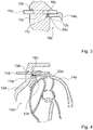
- FIG. 3 schematically a drive train device for a motor vehicle in a third embodiment is shown.
- the drive train device has a first component 10c, an element 11c partially cast into the first component 10c, and a second component 14c, which is materially connected to the cast-in element 11c.
- the drive train device has a sealing unit 12c with a sealing element 16c which seals the joint 13c with respect to an inner space 15c enclosed by the first component 10c and the second component 14c.
- the first component 10c has a sealing element receptacle 17c, which receives the sealing element 16c.
- the first component 10c has a projection 33c.
- the sealing element 16c is arranged sealingly between the first component 10c, the second component 14c and the cast-in element 11b. It directly contacts the first component 10, directly the second component 14c and directly the cast-in element 11c.
- the sealing member 16c is sandwiched between the first member 10c, the second member 14c and the molded member 11c.
- the second component 14c engages in the sealing element receptacle 17c.
- the engaging in the sealing element receiving 17c second component 14c deforms the sealing element 16c.
- the second component 14c presses the sealing element 16c against a material of the first component 10c delimiting the sealing element receptacle 17c in the axial direction.
- the second component 14c presses the sealing element 16c axially against the first component 10c. Due to the deformation caused thereby, the sealing element 16c presses against the first component 10c, against the second Component 14c and against the cast-in element 11c.
- the sealing element 16c is arranged axially between the first component 10a and the second component 14c.
- the first component 10c and the second component 14c lack motion inhibition.
- FIG. 4 schematically a drive train device for a motor vehicle in a fourth embodiment is shown.
- the drive train device has a first component 10d, an element 11d, which is partially cast into the first component 10d, and a second component 14d, which is materially connected to the cast-in element 11d.
- the drive train device has a sealing unit 12d with a sealing element 16d, which seals the connection point 13d with respect to an inner space 15d enclosed by the first component 10d and the second component 14d.
- the first component 10d has a sealing element receptacle 17d, which receives the sealing element 16d.
- the first component 10d has a projection 33d.
- the sealing unit 12d is provided to provide a sealing force for sealing the joint 13d due to adhesion.
- the sealing unit 12d has an adhesive sealing element 16d, which seals the connection point 13d between the first component 10d and the cast-in element 11d in a liquid-tight manner.
- the sealing member 16d adheres to seal the joint 13d to the first member 10d, to the second member 14d and to the molded member 11d.
- the sealing element 16d has an adhesion to the material of the first component 10d, to the material of the second component 14d and to the material of the cast-in element 11. In principle, the sealing element 16d can adhere only to the first component 10d and to the cast-in element 11d or only to the first component 10d and the second component 14d.
- the sealing member 16d may basically have adhesion only to the material of the first member 10d and the material of the second member 14d or adhesion to only the material of the first member 10d and the material of the molded member 11d.
- the sealing element 16d fills the sealing element receptacle 17d at least partially.
- the sealing member 16d substantially fills a gap between the first member 10d, the second member 14d and the molded member 11d.
- the sealing element 16d provides a sealing function already after its curing. It seals the joint 13d independently of the second component 14d.
- the sealing element 16d is formed as a sealing compound.
- the sealing element 16d is formed of silicone.
- the sealing element 16d can also be formed from another sealing compound which provides a sealing effect by adhesion, for example from polyurethane.
- the sealing element 16d is injected into the sealing element receptacle 17d, foamed in, poured in, filled in or the like.
- the first component 10d and the second component 14d are connected to one another by means of the cast-in element 11d.
- FIG. 5 schematically a drive train device for a motor vehicle in a fifth embodiment is shown.
- the drive train device has a first component 10e, an element 11e partially cast into the first component 10e, and a second component 14e, which is materially connected to the cast-in element 11e.
- the drive train device has a sealing unit 12e with a sealing element 16e, which seals the joint 13e with respect to an interior 15e enclosed by the first component 10e and the second component 14e.
- the first component 10e has a sealing element receptacle 17e, which receives the sealing element 16e.
- the first component 10e has a projection 33e.
- the sealing element 16e is formed as an adhesive sealing element.
- the second component 14e lacks an engagement in the sealing element receptacle 17e.
- the second component 14e lacks contact with the sealing element 16e.
- the sealing member 16e is sealingly disposed between the first member 10e and the molded member 11e. It only sealingly contacts the first component 10e and the cast-in element 11e.
- the sealing element 16e substantially fills the sealing element receptacle 17e.
- FIG. 6 schematically a drive train device for a motor vehicle in a sixth embodiment is shown.
- the powertrain device includes a first component 10f, an element 11f partially cast in the first component 10f, and a non-component shown second component, which is materially connected to the cast-in element 11f, on.
- the drive train device has a sealing unit 12f, which seals the connection point 13f with respect to an interior, not shown, enclosed by the first component 10f and the second component.
- the molded element 11f partially forms the sealing unit 12f due to its shape.
- a part of the cast-in element 11f which completely surrounds the material of the first component 10f has a special shape which forms the sealing unit 12f through an encapsulation with the first component 10f.
- the sealing unit 12f is formed by a cooperation of the specially shaped part of the cast-in element 11f completely molded in the first component 10f with the material of the first component 10f surrounding the specially shaped part of the cast-in element 11f.
- the part of the cast-in element 11f completely surrounded by the material of the first component 10f is specially shaped.
- the part of the cast-in member 11f surrounding by the material of the first member 10f is shaped such that the first member 10f is shrunk onto the molded member 11f by cooling after a casting operation, thereby sealing the joint 13f.
- the part of the molded member 11f surrounding by the material of the first member 10f is shaped such that a contact point between the first member 10f and the molded member 11f is wound, jagged, wavy or the like.
- the part of the cast-in element 11f surrounding by the material of the first component 10f is in a longitudinal section through the cast-in element 11f, ie in a section along an axis of rotation of the cast-in element 11f corresponding to FIG FIG. 6 , cruciform shaped.
- the cast-in element 11f has a first undercut 35f completely surrounding by the material of the first component 10f and a second undercut 36f completely surrounding by the material of the first component 10f, which provide the specific shape for sealing the joint 13f.
- the molded-in element 11f has two radially extending projections which are completely surrounded by the material of the first member 10f.
- the first undercut 35f and the second undercut 36f each extend radially beyond protruding sides 21f, 22f of the molded element 11f.
- the first undercut 35f and the second undercut 36f extend in opposite radial directions. They are rectangular in the longitudinal section of the cast-in element 11f.
- the cast-in element 11f may additionally or alternatively have at least one undercut which has a different geometric shape in the longitudinal section of the cast-in element 11f, such as a triangular shape, a semicircular shape or the like.
- the cast-in element 11f has only an undercut for forming the sealing unit 12f.
- the drive train device additionally has a sealing element which is provided to provide a sealing force for sealing the connection point 13f due to an at least partially elastic deformation and / or due to an adhesion.
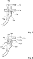
- FIG. 7 schematically a drive train device for a motor vehicle in a seventh embodiment is shown.
- the drive train device has a first component 10g, an element 11g partially cast into the first component 10g and a second component, not shown, which is materially connected to the cast-in element 11g.
- the drive train device has a sealing unit 12g, which seals the joint 13g with respect to a not shown, enclosed by the first component 10g and the second component interior.
- the cast-in element 11g has a plurality of material defects 34g, which are filled in a cast-in state by a material of the first component 10g.
- a part of the cast-in member 11f surrounding the material of the first member 10f for forming the sealing unit 12g has an undercut 36g formed in a longitudinal section through the molded-in member 11g in an L-shape.
- the undercut 36g has an axially extending nose.
- the undercut 36g may also be T-shaped or the like.
- FIG. 8 schematically a drive train device for a motor vehicle in an eighth embodiment is shown.
- the powertrain device has a first one Component 10h, a partially molded into the first component 10h element 11h and a non-illustrated second component, which is materially connected to the cast-in element 11h, on.
- the drive train device has a sealing unit 12h, which seals the connection point 13h with respect to a non-illustrated, enclosed by the first component 10h and the second component interior.
- the cast-in element 11h has a plurality of material defects 34h, which are filled in a cast-in state by a material of the first component 10h.
- the cast-in element 11h has a first undercut 35h and a second undercut 36h, which form an S-shaped section, viewed in a longitudinal section, of a part of the cast-in element 11f surrounding the material of the first component 10f.
- the part of the molded element 11f surrounding by the material of the first member 10f is shaped to form the sealing unit 12h such that a first axially protruding side 21h of the molded element 11h and a second axially protruding side 22h of the molded element 11h are compared are arranged to each other on different radial planes.
Landscapes
- Engineering & Computer Science (AREA)
- General Engineering & Computer Science (AREA)
- Mechanical Engineering (AREA)
- Arrangement Or Mounting Of Propulsion Units For Vehicles (AREA)
- Motor Or Generator Frames (AREA)
- Gasket Seals (AREA)
Description
- Die Erfindung betrifft eine Antriebsstrangvorrichtung für ein Kraftfahrzeug.
- Aus der
EP 1 900 468 A2 und auch aus derUS 3 138 107 A sind bereits Antriebsstrangvorrichtungen für Kraftfahrzeuge, mit einem Bauteil und einem teilweise in das Bauteil eingegossenen Element, wobei das Bauteil und das eingegossene Element aus unterschiedlichen Materialen bestehen, bekannt. - Aus der gattungsgemäßen , der
JP2009168116A
wobei das Bauteil mit zumindest einem weiteren zur Übertragung eines Drehmoments vorgesehenen Bauteil über das eingegossene Element drehmomentübertragend mittelbar verbunden ist, derart, dass das Drehmoment ausschließlich über das eingegossene Element zwischen den Bauteilen übertragen werden kann. - Der Erfindung liegt insbesondere die Aufgabe zugrunde, eine Antriebsstrangvorrichtung in Leichtbauweise wirtschaftlich herzustellen. Diese Aufgabe wird durch eine erfindungsgemäße Ausgestaltung einer Antriebsstrangvorrichtung entsprechend dem Anspruch 1 gelöst. Weiterbildungen der Erfindung ergeben sich aus den abhängigen Ansprüchen.
- Die Erfindung geht aus von einer Antriebsstrangvorrichtung für ein Kraftfahrzeug, mit zumindest einem zur Übertragung eines Drehmoments vorgesehenen Bauteil und zumindest einem teilweise in das Bauteil eingegossenen Element, das zur Übertragung des Drehmoments vorgesehen ist, wobei das Bauteil und das eingegossene Element aus unterschiedlichen Materialen bestehen.
- Es wird vorgeschlagen, dass die Antriebsstrangvorrichtung eine Dichteinheit aufweist, die dazu vorgesehen ist, eine Verbindungsstelle zwischen dem Bauteil und dem eingegossenen Element abzudichten. Durch das in das Bauteil eingegossene Element kann das Bauteil mit zumindest einem weiteren zur Übertragung eines Drehmoments vorgesehenen Bauteil mittelbar über das eingegossene Element drehmomentübertragend verbunden werden, wodurch das Drehmoment über das eingegossene Element zwischen den Bauteilen übertragen werden kann. Dadurch kann das das eingegossene Element aufweisende Bauteil aus einem ersten Material und das weitere Bauteil aus einem von dem ersten Material unterscheidenden zweiten Material gebildet werden, wodurch eine Herstellung der Antriebsstrangvorrichtung, insbesondere aufgrund einer Wahl einer Verbindungsmethode zur drehmomentübertragenden Verbindung der Bauteile, flexibler gestaltet werden kann. Das Material des eingegossenen Elements kann im Hinblick auf eine Verbindung mit dem weiteren Bauteil an das Material des weiteren Bauteils angepasst werden, wodurch die Verbindung zwischen den Bauteilen besonders zuverlässig, robust und kostengünstig ausgeführt werden kann, ohne dabei Einschränkungen bei einer Wahl des Materials der Bauteile hinnehmen zu müssen. Insbesondere kann eines der Bauteile im Vergleich zu dem anderen Bauteil aus einem besonders leichten Material ausgebildet werden, wodurch die Antriebsstrangvorrichtung in ihrem Gewicht besonders leicht ausgebildet und ein Kraftstoffverbrauch des die Antriebsstrangvorrichtung aufweisenden Kraftfahrzeugs reduziert werden kann.
- Da das Bauteil und das in dem Bauteil eingegossene Element aus unterschiedlichen Materialien bestehen, kann insbesondere aufgrund unterschiedlicher Wärmeausdehnungskoeffizienten ein Sitz des eingegossenen Elements in dem Bauteil im Hinblick einer Dichtheit negativ beeinflusst werden, wodurch eine Leckage durch die Verbindungsstelle auftreten kann. Durch die zur Abdichtung der Verbindungsstelle, an der das Bauteil und das eingegossene Element durch einen Guss formschlüssig verbunden sind, vorgesehene Dichteinheit kann eine mögliche Leckage durch die Verbindungsstelle verhindert werden. Es kann eine Dichtheit der Verbindungsstelle und damit der drehmomentübertragenden Verbindung zwischen den Bauteilen sichergestellt werden, wodurch eine Leckage in der Antriebsstrangvorrichtung zuverlässig verhindert werden kann. Die Antriebsstrangvorrichtung kann dadurch besonders wirtschaftlich in Leichtbauweise hergestellt werden, ohne eine Qualität der Antriebsstrangvorrichtung zu reduzieren.
- Unter einem "eingegossenen Element" soll insbesondere ein Element verstanden werden, dass durch einen Gießvorgang, insbesondere einen Spritzgussvorgang, des gegossenen Bauteils mit diesem Bauteil formschlüssig verbunden wird. Das eingegossene Element ist vorteilhaft ringförmig ausgebildet, wodurch die Verbindung zwischen dem Bauteil und dem eingegossenen Element zuverlässiger gestaltet werden kann. Unter "teilweise in das Bauteil eingegossen" soll insbesondere verstanden werden, dass das eingegossene Element zumindest einseitig aus dem Material des Bauteils herausragt. Unter einer "Verbindungsstelle" soll insbesondere eine Stelle verstanden werden, an der das Bauteil und das in das Bauteil eingegossene Element aufgrund eines Gießvorgangs des Bauteils formschlüssig miteinander verbunden sind. Vorzugsweise unterscheiden sich das Material des das eingegossene Element aufweisenden Bauteils und das Material des eingegossenen Elements zumindest in einem Wärmeausdehnungskoeffizienten. Unter einer "Dichteinheit" soll insbesondere eine Einheit verstanden werden, die dazu vorgesehen ist, eine Dichtwirkung zur Abdichtung der Verbindungsstelle bereitzustellen, wobei die Dichtwirkung durch zumindest ein Dichtelement, durch eine spezielle Anordnung wenigstens eines Bauteils und/oder Elements der Antriebsstrangvorrichtung, durch eine spezielle Formgebung wenigstens eines Bauteils und/oder Elements der Antriebsstrangvorrichtung, durch ein spezielles Material wenigstens eines Bauteils und/oder Elements der Antriebsstrangvorrichtung und/oder durch einen speziellen Umguß des eingegossenen Elements bereitgestellt werden kann. Unter "vorgesehen" soll insbesondere speziell ausgebildet, ausgelegt, ausgestattet und/oder angeordnet verstanden werden.
- Besonders vorteilhaft ist es, wenn das das eingegossene Element aufweisende Bauteil zumindest im Wesentlichen aus einem als Leichtmetall ausgebildeten Material besteht und das eingegossene Element zumindest im Wesentlichen aus einem überwiegend eisenhaltigen Material besteht, wodurch das Gewicht der Antriebsstrangvorrichtung reduziert werden kann. Unter einem "Leichtmetall" soll insbesondere ein Metall und/oder eine Legierung verstanden werden, deren Dichte unter 5g/cm3 liegt, wie insbesondere Aluminium. Unter "im Wesentlichen" soll insbesondere zumindest zu 60%, vorteilhaft zumindest zu 80% und besonders vorteilhaft zumindest zu 90% verstanden werden.
- Weiter wird vorgeschlagen, dass die Antriebsstrangvorrichtung zumindest ein weiteres zur Übertragung des Drehmoments vorgesehenes Bauteil aufweist, das gemeinsam mit dem anderen Bauteil zumindest teilweise einen Innenraum einschließt, wobei die Dichteinheit dazu vorgesehen ist, die Verbindungsstelle und den Innenraum gegeneinander abzudichten. Dadurch kann eine Leckage, insbesondere eine Ölleckage, aus dem Innenraum durch die Verbindungsstelle in eine Umgebung verhindert werden.
- Das weitere Bauteil besteht vorteilhaft zumindest im Wesentlichen aus einem überwiegend eisenhaltigen Material. Vorzugsweise ist das eingegossene Element als ein Verbindungselement ausgebildet, welches zur Herstellung einer drehmomentübertragenden Verbindung zwischen den Bauteilen mit dem weiteren Bauteil stoffschlüssig verbunden ist. Durch die stoffschlüssige Verbindung kann auf eine aufwendige und kostenintensive Verbindungsmethode, wie insbesondere Schrauben, Nieten und Schweißnieten, verzichtet werden, wodurch Kosten der Antriebsstrangvorrichtung in Leichtbauweise reduziert werden können. Dadurch können zumindest zwei Bauteile der Antriebsstrangvorrichtung, wobei eines der Bauteile aus dem als Leichtmetall ausgebildeten Material besteht, besonders kostengünstig drehmomentübertragend miteinander verbunden werden, wodurch eine Antriebsstrangvorrichtung in Leichtbauweise wirtschaftlich hergestellt werden kann. Vorzugsweise sind das eingegossene Element und das weitere Bauteil miteinander verschweißt und/oder verlötet.
- Ferner wird vorgeschlagen, dass die Dichteinheit dazu vorgesehen ist, aufgrund einer zumindest teilelastischen Verformung und/oder aufgrund einer Anhaftung eine Dichtkraft zur Abdichtung der Verbindungsstelle bereitzustellen, wodurch die Verbindungsstelle besonders zuverlässig abgedichtet werden kann. Die Dichteinheit, die dazu vorgesehen ist, aufgrund einer zumindest teilelastischen Verformung eine Dichtkraft zur Abdichtung der Verbindungsstelle bereitzustellen, weist vorzugsweise wenigstens ein zumindest teilelastisches Dichtelement auf, das seine Dichtwirkung insbesondere nach seiner zumindest teilelastischen Verformung bereitstellt. Das zumindest teilelastische Dichtelement ist vorteilhaft als eine Dichtungsscheibe, als ein Dichtring oder dergleichen ausgebildet. Vorzugsweise besteht das zumindest teilelastische Dichtelement wenigstens zum Teil aus Gummi, Kautschuk, Polyethylen, Polytetrafluorethylen oder dergleichen. Grundsätzlich kann das zumindest teilelastische Dichtelement auch zumindest teilweise aus Metall bestehen, wie beispielsweise Kupfer. Weiter ist es grundsätzlich denkbar, dass die Dichteinheit, die dazu vorgesehen ist, aufgrund der zumindest teilelastischen Verformung die Dichtkraft zur Abdichtung der Verbindungsstelle bereitzustellen, einstückig mit einem der Bauteile oder dem eingegossenen Element ausgebildet ist. Die Dichteinheit, die dazu vorgesehen ist, aufgrund einer Anhaftung eine Dichtkraft zur Abdichtung der Verbindungsstelle bereitzustellen, weist vorzugsweise zumindest ein anhaftendes Dichtelement auf, das seine Dichtwirkung insbesondere nach seiner Aushärtung bereitstellt. Das anhaftende Dichtelement ist vorteilhaft als ein Silikonkautschuk, ein Silikonelastomer, ein synthetisches Polymer oder dergleichen ausgebildet. Ferner ist es grundsätzlich denkbar, die Dichteinheit durch gezieltes Gießen des Bauteils wenigstens im Bereich der Verbindungsstelle zu realisieren.
- Insbesondere ist es vorteilhaft, wenn die Dichteinheit zumindest ein Dichtelement aufweist, das dichtend zwischen den zwei Bauteilen angeordnet ist, wodurch eine besonders hohe Dichtkraft bereitgestellt werden kann. Unter einem "Dichtelement, das dichtend zwischen den zwei Bauteilen angeordnet ist" soll insbesondere ein Dichtelement verstanden werden, das beide Bauteile dichtend kontaktiert.
- Weiter ist es vorteilhaft, wenn die Dichteinheit zumindest ein Dichtelement aufweist, das dichtend zwischen zumindest einem der Bauteile und dem eingegossenen Element angeordnet ist, wodurch eine Montage der zwei Bauteile vereinfacht werden kann. Unter einem "Dichtelement, das dichtend zwischen zumindest einem der Bauteile und dem eingegossenen Element angeordnet ist" soll insbesondere ein Dichtelement verstanden werden, das zumindest eines der Bauteile und das eingegossene Element dichtend kontaktiert.
- Ferner ist es vorteilhaft, wenn zumindest eines der Bauteile wenigstens eine Dichtelementaufnahme aufweist, die das zumindest eine Dichtelement wenigstens teilweise aufnimmt, wodurch eine Montage des Dichtelements vereinfacht werden kann.
- Um das Dichtelement dichtend zwischen den beiden Bauteilen anzuordnen, greift in einer weiteren erfindungsgemäßen Ausgestaltung zumindest eines der Bauteile zumindest teilweise in die Dichtelementaufnahme ein, wodurch das Dichtelement zur Abdichtung der Verbindungsstelle von dem eingreifenden Bauteil zumindest teilelastisch verformt werden kann.
- Des Weiteren wird vorgeschlagen, dass zumindest eines der Bauteile eine Bewegungshemmung für das Dichtelement aufweist, die dazu vorgesehen ist, eine Bewegung des Dichtelements in der Dichtelementaufnahme zumindest zu erschweren, wodurch ein sicherer Sitz des Dichtelements bereitgestellt werden kann. Die Bewegungshemmung ist vorteilhaft als eine Nut ausgebildet, in der das Dichtelement innerhalb der Dichtelementaufnahme angeordnet ist. Vorzugsweise kann die Bewegungshemmung auch durch eine angeraute oder strukturierte Oberfläche in der Dichtelementaufnahme ausgebildet sein. Unter einer "angerauten Oberfläche" soll insbesondere eine Oberfläche verstanden werden, die eine makroskopische Rauheit mit einer mittleren Rauhigkeitshöhe von 0,05 bis 0,2 Millimeter aufweist. Unter einer "strukturierten Oberfläche" soll insbesondere eine Oberfläche verstanden werden, die eine makroskopische Rauheit mit einer mittleren Rauhigkeitshöhe von 0,1 bis 1,5 Millimeter aufweist. Vorzugsweise weist die strukturierte Oberfläche mit bloßem Auge erkennbare Erhöhungen und Vertiefungen auf wie beispielsweise Riefen, Stege, Noppen oder dergleichen.
- In einer vorteilhaften Ausgestaltung ist das eingegossene Element dazu vorgesehen, aufgrund seiner Form die Dichteinheit zumindest teilweise auszubilden, wodurch die Verbindungsstelle besonders kompakt und montagefreundlich abgedichtet werden kann. Vorzugsweise weist ein Teil des eingegossenen Elements, der vollständig von dem Material des gegossenen Bauteils umgeben ist, eine Form auf, die zu Ausbildung der Dichteinheit vorgesehen ist, wodurch die Verbindungsstelle von außen unsichtbar abgedichtet werden kann. Vorteilhaft ist der durch das Material des gegossenen Bauteils vollständig umgebene Teil des eingegossenen Elements in der Art geformt, so dass das gegossene Bauteil bei oder durch eine Abkühlung des Materials des gegossenen Bauteils nach dem Gießvorgang auf das eingegossene Element aufgeschrumpft wird. Unter einem "gegossenen Bauteil" soll insbesondere das Bauteil verstanden werden, in das das eingegossene Element teilweise eingegossen ist.
- Weiter ist es vorteilhaft, wenn das eingegossene Element zumindest einen durch das Material des gegossenen Bauteils umgebenden Hinterschnitt aufweist, der dazu vorgesehen ist, die Dichteinheit zumindest teilweise auszubilden. Dadurch kann der Teil des eingegossenen Elements, welcher durch das Material des gegossenen Bauteils vollständig umgeben ist, zur Bereitstellung der Dichtwirkung genutzt werden, wodurch auf separate Dichtelemente verzichtet werden kann.
- Besonders vorteilhaft ist es, wenn zumindest eines der Bauteile wenigstens teilweise ein Drehmomentwandlergehäuse ausbildet, wodurch ein Drehmomentwandler in Leichtbauweise wirtschaftlich hergestellt werden kann. Durch die stoffschlüssige Verbindung des eingegossenen Elements mit dem weiteren Bauteil kann ferner eine aufwendige Einstellung eines Axialspiels zwischen Bauteilen vermieden werden, wobei insbesondere bei Montage des Drehmomentwandlergehäuses auf Ausgleichselemente, die beispielsweise bei einer Schraubverbindung notwendig sind, verzichtet werden kann. Unter einem "Drehmomentwandlergehäuse" soll insbesondere ein Gehäuse verstanden werden, dass zumindest ein Bauteil des Drehmomentwandlers wenigstens teilweise umgibt und/oder aufnimmt.
- Insbesondere ist es vorteilhaft, wenn eines der Bauteile ein Pumpenrad und das andere Bauteil zumindest teilweise einen Außenlamellenträger ausbildet, wodurch ein kostengünstiger Drehmomentwandler mit einer Wandlerüberbrückungskupplung in Leichtbauweise bereitgestellt werden kann.
- Ferner wird ein Herstellverfahren zur Herstellung einer Antriebsstrangvorrichtung eines Kraftfahrzeugs, insbesondere einer erfindungsgemäßen Antriebsstrangvorrichtung, vorgeschlagen, bei dem eine Verbindungsstelle zwischen einem zur Übertragung eines Drehmoments vorgesehenen Bauteil, bestehend aus einem ersten Material, und zumindest einem teilweise in das Bauteil eingegossenen und zur Übertragung des Drehmoments vorgesehenen Element, bestehend aus einem von dem ersten Material unterscheidenden zweiten Material, abgedichtet wird, bevor ein weiteres zur Übertragung des Drehmoments vorgesehenes Bauteil drehmomentübertragend mit dem eingegossenen Element verbunden wird.
- Weitere Vorteile ergeben sich aus der folgenden Figurenbeschreibung. In den Figuren sind acht Ausführungsbeispiele der Erfindung dargestellt. Die Figuren, die Figurenbeschreibung und die Ansprüche enthalten zahlreiche Merkmale in Kombination. Der Fachmann wird die Merkmale zweckmäßigerweise auch einzeln betrachten und zu sinnvollen weiteren Kombinationen zusammenfassen.
- Dabei zeigen:
- Fig. 1
- teilweise und schematisiert eine Antriebstrangvorrichtung mit einem als Pumpenrad eines Drehmomentwandlers ausgebildeten Bauteil, einem als Außenlamellenträger einer Wandlerüberbrückungskupplung ausgebildeten Bauteil, einem in das als Außenlamellenträger ausgebildete Bauteil eingegossenen Element, das stoffschlüssig mit dem als Pumpenrad ausgebildeten Bauteil verbunden ist, und mit einer Dichteinheit, die eine Versbindungsstelle zwischen dem als Außenlamellenträger ausgebildeten Bauteil und dem eingegossenen Element abdichtet,
- Fig. 2
- eine Antriebsstrangvorrichtung mit einer alternativ ausgebildeten Dichteinheit,
- Fig. 3
- eine Antriebsstrangvorrichtung mit einer Dichteinheit in einem dritten Ausführungsbeispiel,
- Fig. 4
- eine Antriebsstrangvorrichtung mit einer Dichteinheit in einem vierten Ausführungsbeispiel,
- Fig. 5
- eine Antriebsstrangvorrichtung mit einer Dichteinheit in einem fünften Ausführungsbeispiel,
- Fig. 6
- eine Antriebsstrangvorrichtung mit einer Dichteinheit in einem sechsten Ausführungsbeispiel,
- Fig. 7
- eine Antriebsstrangvorrichtung mit einer Dichteinheit in einem siebten Ausführungsbeispiel und
- Fig. 8
- eine Antriebsstrangvorrichtung mit einer Dichteinheit in einem achten Ausführungsbeispiel.
-
Figur 1 zeigt eine Antriebsstrangvorrichtung für ein nicht näher dargestelltes Kraftfahrzeug, die für einen Antriebsstrang des Kraftfahrzeugs vorgesehen ist. Die Antriebsstrangvorrichtung weist ein nicht näher dargestelltes Automatikgetriebe und einen hydraulischen Drehmomentwandler 20a mit einer Wandlerüberbrückungskupplung auf. Der Drehmomentwandler 20a weist dabei ein Pumpenrad, ein Turbinenrad und ein Leitrad auf. Die Wandlerüberbrückungskupplung weist einen Außenlamellenträger, der drehfest mit dem Pumpenrad verbunden ist, und einen Innenlamellenträger, der drehfest mit dem Turbinenrad verbunden ist, auf. - Die Antriebsstrangvorrichtung weist weiter ein erstes zur Übertragung eines Drehmoments vorgesehenes Bauteil 10a und ein zweites zur Übertragung eines Drehmoments vorgesehenes Bauteil 14a auf, die drehmomentübertragend miteinander verbunden sind. Zur Aufnahme des ersten Bauteils 10a und des zweiten Bauteils 14a weist die Antriebsstrangvorrichtung ein nicht näher dargestelltes Gehäuse auf, innerhalb dessen das erste Bauteil 10a und das zweite Bauteil 14a angeordnet sind. Das erste Bauteil 10a und das zweite Bauteil 14a sind dabei relativ zu dem nicht dargestellten Gehäuse drehbar gelagert.
- Das erste Bauteil 10a und das zweite Bauteil 14a bestehen aus unterschiedlichen Materialien. Das erste Bauteil 10a besteht aus einem anderen Material als das zweite Bauteil 14a. Um eine Leichtbauweise zu realisieren, besteht das erste Bauteil 10a aus einem als Leichtmetall ausgebildeten Material. Das erste Bauteil 10a besteht aus Aluminium. Dabei ist das erste Bauteil 10a als ein Gussteil ausgebildet. Das erste Bauteil 10a ist somit gegossen. Das zweite Bauteil 14a besteht aus einem überwiegend eisenhaltigen Material. Das zweite Bauteil 14a besteht aus Stahl.
- Um das erste Bauteil 10a und das zweite Bauteil 14a drehmomentübertragend miteinander zu verbinden, weist die Antriebsstrangvorrichtung ein Element 11a auf, das das Drehmoment zwischen dem ersten Bauteil 10a und dem zweiten Bauteil 14a überträgt. Das Element 11a ist teilweise in das erste Bauteil 10a eingegossen. Dabei besteht das eingegossene Element 11a aus einem anderen Material als das erste Bauteil 10a. Das eingegossene Element 11a besteht aus einem überwiegend eisenhaltigen Material. Es besteht aus Stahl. Durch das Eingießen wird an einer Verbindungsstelle 13a eine formschlüssige Verbindung zwischen dem aus Aluminium bestehenden ersten Bauteil 10a und dem aus Stahl bestehenden Element 11a bereitgestellt. Das eingegossene Element 11a ist als ein Verbindungselement ausgebildet, das die drehmomentübertragende Verbindung zwischen dem ersten Bauteil 10a und dem zweiten Bauteil 14a herstellt. Dazu sind das in das erste Bauteil 10a eingegossene Element 11a und das zweite Bauteil 14a stoffschlüssig miteinander verbunden. Das eingegossene Element 11a und das zweite Bauteil 14a weisen somit eine stoffschlüssige Verbindungsstelle 13a auf. In diesem Ausführungsbeispiel sind das aus Stahl bestehende zweite Bauteil 14a und das aus Stahl bestehende eingegossene Element 11a miteinander verschweißt. Sie sind durch eine Schweißverbindung miteinander verbunden. Das aus Stahl bestehende zweite Bauteil 14a und das aus Aluminium bestehende erste Bauteil 10a sind über das in dem ersten Bauteil 10a eingegossene Element 11a drehmomentübertragend miteinander verbunden. Die stoffschlüssige Verbindungsstelle 13a ist als eine Schweißstelle ausgebildet. Das erste Bauteil 10a und das zweite Bauteil 14a sind mittels einer Stahl-Stahl-Fügung miteinander verbunden. Grundsätzlich können das zweite Bauteil 14a und das eingegossene Element 11a alternativ oder zusätzlich miteinander verlötet und/oder verklebt sein. Um Kosten einzusparen kann das eingegossene Element 11a grundsätzlich aus Blechstreifen wie ein Puzzle verbaut werden.
- Das eingegossene Element 11a ragt axial beidseitig aus dem Material des ersten Bauteils 10a heraus. Das eingegossene Element 11a weist eine erste axial aus dem Material des ersten Bauteils 10a herausragende Seite 21a und eine zweite axial aus dem Material des ersten Bauteils 10a herausragende Seite 22a auf. Die erste axial herausragende Seite 21a des eingegossenen Elements 11a ist zur stoffschlüssigen Anbindung an das zweite Bauteil 14a vorgesehen. Mit der ersten axial herausragenden Seite 21a ist das eingegossene Element 11a mit dem zweiten Bauteil 14a stoffschlüssig verbunden. Die axial gegenüberliegende zweite axial herausragende Seite 22a des eingegossenen Elements 11a ist zur Auswuchtung vorgesehen. Die zweite axial herausragende Seite 22a weist zur Auswuchtung ein Wuchtelement 23a auf. Das Wuchtelement 23a ist zur Beseitigung einer Unwucht auf der zweiten axial herausragenden Seite 22a fest auf dem eingegossenen Element 11a angeordnet. Das Wuchtelement 23a ist als ein Wuchtblech ausgebildet. Grundsätzlich kann die zweite axial herausragende Seite 22a zur Auswuchtung zusätzlich oder alternativ wenigstens eine Wuchtausnehmung aufweisen, die als eine Materialwegnahme ausgebildet ist. Weiter ist es grundsätzlich denkbar, dass ein positives Wuchten durch ein CMT-Schweißen auf der zweiten axial herausragenden Seite 22a durchgeführt wird.
- Um eine Gussverbindung zwischen dem ersten Bauteil 10a und dem eingegossenen Element 11a zuverlässiger zu gestalten, weist das eingegossene Element 11a mehrere Materialfehlstellen 34a auf, die in einem eingegossenen Zustand von dem Material des ersten Bauteils 10a ausgefüllt sind. Die Materialfehlstellen 34a sind dabei axial zwischen den axial herausragenden Seiten 21a, 22a angeordnet. Die Materialfehlstellen 34a sind gleichmäßig um einen Umfang des eingegossenen Elements 11a angeordnet. Sie sind als Bohrungen ausgebildet. Das erste Bauteil 10a und das eingegossene Element 11a sind in einem Schnitt durch eine solche Materialfehlstelle 34a dargestellt. Das eingegossene Element 11a ist ringförmig ausgebildet. Es ist als ein Verbindungsring ausgebildet.
- Das erste Bauteil 10a und das zweite Bauteil 14a schließen einen Innenraum 15a ein, der zumindest in einem Betrieb mit einem flüssigen Betriebsmittel gefüllt ist. Das erste Bauteil 10a und das zweite Bauteil 14a bildet ein Drehmomentwandlergehäuse des Drehmomentwandlers 20a aus. In dem Innenraum 15a und damit innerhalb des ersten Bauteils 10a und des zweiten Bauteils 14a sind Bauteile 24a, 25a, 26a, 27a des Drehmomentwandlers 20a angeordnet. Das erste Bauteil 10a bildet einstückig den Außenlamellenträger der Wandlerüberbrückungskupplung und das zweite Bauteil 14a einstückig das Pumpenrad des Drehmomentwandlers 20a aus. Das Betriebsmittel mit dem der Innenraum 15a zumindest in dem Betrieb gefüllt ist, ist als Öl ausgebildet.
- Das innerhalb der Bauteile 10a, 14a angeordnete Bauteil 24a ist als das Turbinenrad, die innerhalb der Bauteile 10a, 14a angeordneten Bauteile 25a sind jeweils als eine Turbinenradschaufel, das innerhalb der Bauteile 10a, 14a angeordnete Bauteil 26a ist als das Leitrad und die innerhalb der Bauteile 10a, 14a angeordneten Bauteile 27a sind jeweils als eine Pumpenradschaufel des Drehmomentwandlers 20a ausgebildet. Somit ist der Außenlamellenträger aus Aluminium hergestellt und durch das eingegossene Element 11a mit dem aus Stahl ausgebildeten Pumpenrad des Drehmomentwandlers 20a verbunden, wobei dazu das Pumpenrad und das eingegossene Element 11a miteinander verschweißt sind. Grundsätzlich kann das erste Bauteil 10a mit dem Außenlamellenträger der Wandlerüberbrückungskupplung und das zweite Bauteil 14a mit dem Pumpenrad des Drehmomentwandlers 20a lediglich fest verbunden sein.
- Die Antriebsstrangvorrichtung weist weiter eine Schöpfvorrichtung 28a auf, die bei einer Rotation aufgrund einer Adhäsion ein Kühlmittel aus einem Kühlmittelsumpf mitnimmt und damit schöpft. Die Schöpfvorrichtung 28a befördert dabei das Kühlmittel auf ein höheres Niveau, von dem es aufgrund einer Schwerkraft am ersten Bauteil 10a und am zweiten Bauteil 14a wieder abfließt. Das erste Bauteil 10a bildet einstückig die Schöpfvorrichtung 28a aus. Die Schöpfvorrichtung 28a ist bezüglich einer Rotationsachse des ersten Bauteils 10a und des zweiten Bauteils 14a radial außerhalb des eingegossenen Elements 11a angeordnet. Die Schöpfvorrichtung 28a umgibt die erste axial herausragende Seite 21a des eingegossenen Elements 11a. Das Kühlmittel ist dabei als ein Öl ausgebildet.
- Die Schöpfvorrichtung 28a weist eine erste stirnseitige Materialfehlstelle 29a und eine gegenüberliegende zweite stirnseitige Materialfehlstelle 30a auf. Die Materialfehlstellen 29a, 30a bilden Rinnen aus, die in axialer Richtung geöffnet sind. Sie verlaufen dabei jeweils stirnseitig um den Umfang der Schöpfvorrichtung 28a. Die erste Materialfehlstelle 29a ist bezüglich der Rotationsachse radial über der ersten axial herausragenden Seite 21a des eingegossenen Elements 11a angeordnet. Die Materialfehlstellen 29a, 30a weisen unterschiedliche Ausmaße auf. Die erste Materialfehlstelle 29a ist dabei größer ausgebildet als die zweite Materialfehlstelle 30a. Die erste Materialfehlstelle 29a ist axial tiefer als die zweite Materialfehlstelle 30a. Die Materialfehlstellen 29a, 30a sind jeweils durch das Gießen des ersten Bauteils 10a ausgeformt. Sie sind jeweils ringförmig.
- Aufgrund der axial gegenüberliegenden Materialfehlstellen 29a, 30a weist die Schöpfvorrichtung 28a einen Schöpfring 31a und eine Materialeinschnürung 32a auf. Die Materialeinschnürung 32a verbindet das erste Bauteil 10a und den Schöpfring 31a einstückig miteinander. Der Schöpfring 31a ist dabei radial über der Materialeinschnürung 32a angeordnet. Der Schöpfring 31a und die Materialeinschnürung 32a verlaufen um einen Umfang des ersten Bauteils 10a. Ausgehend von der Materialeinschnürung 32a weist der Schöpfring 31a unterschiedliche Axialerstreckungen auf. Eine axiale Erstreckung des Schöpfrings 31a ausgehend von der Materialeinschnürung 32a in Richtung der ersten axial herausragenden Seite 21a des eingegossenen Elements 11a ist dabei größer als eine axiale Erstreckung des Schöpfrings 31a ausgehend von der Materialeinschnürung 32a in Richtung der zweiten axial herausragenden Seite 22a des eingegossenen Elements 11a. Der Schöpfring 31a erstreckt sich ausgehend von der Materialeinschnürung 32a axial im Wesentlichen in Richtung der ersten axial herausragenden Seite 21a des eingegossenen Elements 11a. Der Schöpfring 31a überdacht die erste axial herausragende Seite 21a des eingegossenen Elements 11a. Der Schöpfring 31a überdacht damit die stoffschlüssige Verbindungsstelle 13a zwischen dem zweiten Bauteil 14a und dem eingegossenen Element 11a. Eine Überdachung der zweiten axial herausragenden Seite 22a des eingegossenen Elements 11a durch den Schöpfring 31a fehlt. Es fehlt damit eine Überdachung des Wuchtelements 23a durch den Schöpfring 31a. In einem Schnitt entlang der Rotationsachse entsprechend der
Figur 1 weist die Schöpfvorrichtung 28a eine Ambossform auf. Dabei erstreckt sich der radial über der Materialeinschnürung 32a angeordnete Schöpfring 31a axial im Wesentlichen in Richtung der ersten axial herausragenden Seite 21a des eingegossenen Elements 11a. - Um sicherzustellen, dass die Verbindungsstelle 13a zwischen dem ersten Bauteil 10a und dem eingegossenen Element 11a flüssigkeitsdicht ist, weist die Antriebsstrangvorrichtung eine Dichteinheit 12a auf, die die Verbindungsstelle 13a zwischen dem ersten Bauteil 10a und dem eingegossenen Element 11a flüssigkeitsdicht abdichtet. Die Dichteinheit 12a dichtet die Verbindungsstelle 13a und den Innenraum 15a gegeneinander ab und verhindert dadurch, dass das Betriebsmittel aus dem Innenraum 15a ungewollt durch die Verbindungsstelle 13a aus dem Innenraum 15a austritt.
- Die Dichteinheit 12a ist dazu vorgesehen, aufgrund einer elastischen Verformung eine Dichtkraft zur Abdichtung der Verbindungsstelle 13a bereitzustellen. Die Dichteinheit 12a weist ein elastisch verformbares Dichtelement 16a auf, dass die Verbindungsstelle 13a zwischen dem ersten Bauteil 10a und dem eingegossenen Element 11a flüssigkeitsdicht abdichtet. Das Dichtelement 16a stellt eine Dichtfunktion erst nach seiner elastischen Verformung bereit. Grundsätzlich kann die Dichteinheit 12a einstückig durch das erste Bauteil 10a und/oder durch das zweite Bauteil 14a gebildet sein, beispielsweise durch eine Materialerhebung oder dergleichen.
- Das Dichtelement 16a ist innerhalb des ersten Bauteils 10a angeordnet. Das erste Bauteil 10a umgibt das Dichtelement 16a. Das Dichtelement 16a läuft um die Rotationsachse der Bauteile 10a, 14a herum. Es ist endlos ausgebildet. Das Dichtelement 16a ist separat zu den Bauteilen 10a, 14a ausgebildet. Das Dichtelement 16a ist als ein Dichtring ausgebildet. Das Dichtelement 16a ist aus Gummi gebildet. Grundsätzlich kann das Dichtelement 16a auch aus einem anderen Material, welches durch zumindest ein teilelastisches Verhalten eine Dichtwirkung bereitstellt, gebildet sein, wie beispielsweise aus Kupfer. Weiter ist es grundsätzlich denkbar, dass die Dichteinheit 12a mehrere Dichtelemente aufweist. Das Dichtelement 16a weist einen runden Querschnitt auf. Grundsätzlich kann der Querschnitt auch elliptisch, eckig oder dergleichen sein. Ferner ist es denkbar, dass das Dichtelement 16a verwunden, verdrillt, kurvig oder dergleichen um die Rotationsachse verläuft.
- Das Dichtelement 16a ist dichtend zwischen dem ersten Bauteil 10a und dem zweiten Bauteil 14a angeordnet. Es kontaktiert direkt das erste Bauteil 10 und direkt das zweite Bauteil 14a. Das Dichtelement 16a ist zwischen dem ersten Bauteil 10a und dem zweiten Bauteil 14a eingeklemmt. Das Dichtelement 16a ist innerhalb des zweiten Bauteils 14a angeordnet. Das zweite Bauteil 10a umgibt das Dichtelement 16a.
- Zur Anordnung des Dichtelements 16a weist das erste Bauteil 10a eine Dichtelementaufnahme 17a auf, die das Dichtelement 16a aufnimmt. Die Dichtelementaufnahme 17a ist als eine Materialfehlstelle ausgebildet. Die Dichtelementaufnahme 17a ist in Richtung des zweiten Bauteils 14a geöffnet. Sie ist ringförmig ausgebildet. Die Dichtelementaufnahme 17a ist in Form einer Rinne ausgebildet, die in axialer Richtung geöffnet ist. Die Dichtelementaufnahme 17a ist bezüglich der Rotationsachse der Bauteile 10a, 14a radial innerhalb des eingegossenen Elements 11a angeordnet. Die Dichtelementaufnahme 17a ist in eine dem zweiten Bauteil 14a abgewandte Richtung axial und in eine der Rotationsachse zugewandte Richtung radial durch das erste Bauteil 10a begrenzt. In eine der Rotationsachse abgewandte Richtung ist die Dichtelementaufnahme 17a radial durch das eingegossene Element 11a begrenzt. Grundsätzlich kann die Dichtelementaufnahme 17a in Form einer Rille, einer Kerbe, einer Tasche oder dergleichen ausgebildet sein.
- Zur Ausbildung der Dichtelementaufnahme 17a weist das erste Bauteil 10a einen Vorsprung 33a auf. Der Vorsprung 33a ist radial unterhalb des eingegossenen Elements 11a angeordnet. Er erstreckt sich ausgehend von einer dem zweiten Bauteil 14a zugewandten Oberfläche des ersten Bauteils 10a axial in Richtung des zweiten Bauteils 14a. Das Dichtelement 16a stützt sich an dem Vorsprung 33a ab. Es ist auf dem Vorsprung 33a angeordnet. Die Dichtelementaufnahme 17a ist durch das Gießen des ersten Bauteils 10a gebildet.
- Zur positionssicheren Anordnung des Dichtelements 16a weist das erste Bauteil 10a eine Bewegungshemmung 18a für das Dichtelement 16a auf, die eine axiale Bewegung des Dichtelements 16a in der Dichtelementaufnahme 17a erschwert. Die Bewegungshemmung 18a positioniert das Dichtelement 16a in der Dichtelementaufnahme 17a. Sie positioniert das Dichtelement 16a auf dem Vorsprung 33a. Die Bewegungshemmung 18a ist als eine Vertiefung in der Dichtelementaufnahme 17a ausgebildet, die dazu vorgesehen ist, das Dichtelement 16a aufzunehmen. Die Bewegungshemmung 18a ist in den Vorsprung 33a eingebracht. Sie ist radial in Richtung des eingegossenen Elements 11a geöffnet. Die Bewegungshemmung 18a fixiert axial das Dichtelement 16a auf dem Vorsprung 33a. Eine Form der Bewegungshemmung 18a ist an eine Form des Dichtelements 16a angepasst. Die Bewegungshemmung 18a ist als eine Nut ausgebildet. Grundsätzlich kann die Bewegungshemmung 18a auch als eine angeraute oder strukturierte Oberfläche ausgebildet sein.
- Zur Bereitstellung der Dichtkraft greift das zweite Bauteil 14a in die Dichtelementaufnahme 17a ein. Das in die Dichtelementaufnahme 17a eingreifende zweite Bauteil 14a verformt das Dichtelement 16a. Das zweite Bauteil 14a drückt das Dichtelement 16a radial gegen das erste Bauteil 10a. Es drückt das Dichtelement 16a radial gegen den Vorsprung 33a. Das zweite Bauteil 14a ist teilweise radial zwischen dem eingegossenen Element 11a und dem Vorsprung 33a angeordnet. Das zweite Bauteil 14a ist in die Dichtelementaufnahme 17a eingesteckt. Alternativ oder zusätzlich kann das zweite Bauteil 14a eine Bewegungshemmung aufweisen, die die Bewegung des Dichtelements 16a in der Dichtelementaufnahme 17a erschwert.
- In einem Herstellverfahren zur Herstellung der Antriebsstrangvorrichtung wird das aus dem eisenhaltigen Material bestehende, als Verbindungselement ausgebildete Element 11a in das aus dem als Leichtmetall ausgebildeten Material bestehende erste Bauteil 10a eingegossen, um eine formschlüssige Verbindung zwischen dem ersten Bauteil 10a und dem eingegossenen Element 11a herzustellen. Zur Anbindung an das zweite Bauteil 14a und zur Auswuchtung wird das eingegossene Element 11a in der Art eingegossen, dass dieses axial beidseitig aus dem Material des ersten Bauteils 10a herausragt.
- Die Verbindungsstelle 13a zwischen dem ersten Bauteil 10a und dem eingegossenen Element 11a wird anschließend abgedichtet, bevor das zweite Bauteil 14a drehmomentübertragend mit dem eingegossenen Element 11a verbunden wird. Dazu wird das Dichtelement 16a auf den Vorsprung 33a gedrückt, bis dieses durch die Bewegungshemmung 18a aufgenommen ist.
- Daraufhin werden die inneren Bauteile 24a, 25a, 26a, 27a in einer Vormontage in dem ersten Bauteil 10a und dem zweiten Bauteil 14a vormontiert, bevor das zweite Bauteil 14a und das eingegossene Element 11a stoffschlüssig miteinander verbunden werden. Nach der Vormontage der inneren Bauteile 24a, 25a, 26a, 27a wird ein richtiges Axialspiel zwischen dem ersten Bauteil 10a und dem zweiten Bauteil 14a eingestellt. Anschließend wird das zweite Bauteil 14a in die Dichtelementaufnahme 17a gesteckt, wodurch das Dichtelement 16a durch das zweite Bauteil 14a verformt wird. Durch die Verformung des Dichtelements 16a mittels dem zweiten Bauteil 14a wird die Verbindungsstelle 13a zwischen dem ersten Bauteil 10a und dem eingegossenen Element 11a abgedichtet. Daraufhin werden das erste Bauteil 10a und das zweite Bauteil 14a drehmomentübertragend miteinander verbunden. Um das aus dem als Leichtmetall ausgebildeten Material bestehende erste Bauteil 10a und das aus dem eisenhaltigen Material bestehende zweite Bauteil 14a drehmomentübertragend miteinander zu verbinden, wird die erste axial herausragende Seite 21a des in das erste Bauteil 10a eingegossenen Elements 11a mit dem zweiten Bauteil 14a stoffschlüssig verbunden. Dabei wird das eingegossene Element 11a und das zweite Bauteil 14a miteinander verschweißt. Die drehmomentübertragende Verbindung des ersten Bauteils 10a mit dem zweiten Bauteil 14a erfolgt unter Verzicht von Spielausgleichselementen.
- Damit wird zuerst das Dichtelement 16a in der Dichtelementaufnahme 17a angebracht, die innerhalb des ersten Bauteils 10a und des zweiten Bauteils 14a angeordneten Bauteile 24a, 25a, 26a, 27a axial mit einem richtigen Spiel zueinander eingestellt, das zweite Bauteil 14a zur Abdichtung der Verbindungsstelle 13a in die Dichtelementaufnahme 17a eingesteckt und erst dann das zweite Bauteil 14a und das eingegossene Element 11a miteinander verschweißt. Es werden keine Spielausgleichselemente, wie Einstellscheiben, benötigt.
- In den
Figuren 2 bis 8 sind sieben weitere Ausführungsbeispiele der Erfindung gezeigt. Die nachfolgenden Beschreibungen beschränken sich im Wesentlichen auf die Unterschiede zwischen den Ausführungsbeispielen, wobei bezüglich gleichbleibender Bauteile, Merkmale und Funktionen auf die Beschreibung der anderen Ausführungsbeispiele, insbesondere derFigur 1 , verwiesen werden kann. Zur Unterscheidung der Ausführungsbeispiele wurde der Buchstabe a in den Bezugszeichen des Ausführungsbeispiels in derFigur 1 durch die Buchstaben b bis h in den Bezugszeichen der Ausführungsbeispiele derFiguren 2 bis 8 ersetzt. Bezüglich gleich bezeichneter Bauteile, insbesondere in Bezug auf Bauteile mit gleichen Bezugszeichen, kann grundsätzlich auch auf die Zeichnungen und/oder die Beschreibung der anderen Ausführungsbeispiele insbesondere derFigur 1 verwiesen werden. - In der
Figur 2 ist schematisch ein Ausschnitt einer Antriebsstrangvorrichtung für ein Kraftfahrzeug in einem zweiten Ausführungsbeispiel dargestellt. Die Antriebsstrangvorrichtung weist ein erstes Bauteil 10b, ein teilweise in das erste Bauteil 10b eingegossenes Element 11b und ein zweites Bauteil 14b, das stoffschlüssig mit dem eingegossenen Element 11b verbunden ist, auf. Zur Abdichtung einer Verbindungsstelle 13b zwischen dem ersten Bauteil 10b und dem eingegossenen Element 11b weist die Antriebsstrangvorrichtung eine Dichteinheit 12b mit einem Dichtelement 16b auf, die die Verbindungsstelle 13b gegenüber einem durch das erste Bauteil 10b und das zweite Bauteil 14b eingeschlossenen Innenraum 15b abdichtet. Zur Anordnung des Dichtelements 16b weist das erste Bauteil 10b eine Dichtelementaufnahme 17b auf, die das Dichtelement 16b aufnimmt. Zur Ausbildung der Dichtelementaufnahme 17b weist das erste Bauteil 10b einen Vorsprung 33b auf. - Im Unterschied zu dem vorherigen Ausführungsbeispiel weist das erste Bauteil 10b zur positionssicheren Anordnung des Dichtelements 16b zwei Bewegungshemmungen 18b, 19b auf, die eine Bewegung des Dichtelements 16b in der Dichtelementaufnahme 17b in zwei verschiedene Richtungen erschweren. Die erste Bewegungshemmung 18b ist dazu vorgesehen eine axiale Bewegung des Dichtelements 16b in der Dichtelementaufnahme 17b und damit auf Vorsprung 33b zu erschweren. Die zweite Bewegungshemmung 19b ist dazu vorgesehen eine radiale Bewegung des Dichtelements 16b in der Dichtelementaufnahme 17b und damit insbesondere auf Vorsprung 33b zu erschweren. Beide Bewegungshemmungen 18b, 19b sind als eine Vertiefung ausgebildet, die dazu vorgesehen ist, das Dichtelement 16b aufzunehmen. Die erste Bewegungshemmung 18b ist in den Vorsprung 33b eingebracht. Die erste Bewegungshemmung 18b ist radial in Richtung des eingegossenen Elements 11b geöffnet. Die zweite Bewegungshemmung 19b ist in einem die Dichtelementaufnahme 17b axial begrenzenden Material des ersten Bauteils 10a eingebracht. Die zweite Bewegungshemmung 19b ist axial in Richtung des zweiten Bauteils 14b geöffnet. Die Bewegungshemmungen 18b, 19b fixieren das Dichtelement 16b radial und axial auf dem Vorsprung 33b.
- In der
Figur 3 ist schematisch eine Antriebsstrangvorrichtung für ein Kraftfahrzeug in einem dritten Ausführungsbeispiel dargestellt. Die Antriebsstrangvorrichtung weist ein erstes Bauteil 10c, ein teilweise in das erste Bauteil 10c eingegossenes Element 11c und ein zweites Bauteil 14c, das stoffschlüssig mit dem eingegossenen Element 11c verbunden ist, auf. Zur Abdichtung einer Verbindungsstelle 13c zwischen dem ersten Bauteil 10c und dem eingegossenen Element 11c weist die Antriebsstrangvorrichtung eine Dichteinheit 12c mit einem Dichtelement 16c auf, die die Verbindungsstelle 13c gegenüber einem durch das erste Bauteil 10c und das zweite Bauteil 14c eingeschlossenen Innenraum 15c abdichtet. Zur Anordnung des Dichtelements 16c weist das erste Bauteil 10c eine Dichtelementaufnahme 17c auf, die das Dichtelement 16c aufnimmt. Zur Ausbildung der Dichtelementaufnahme 17c weist das erste Bauteil 10c einen Vorsprung 33c auf. - Im Unterschied zu den vorherigen Ausführungsbeispielen ist das Dichtelement 16c dichtend zwischen dem ersten Bauteil 10c, dem zweiten Bauteil 14c und dem eingegossenen Element 11b angeordnet. Es kontaktiert direkt das erste Bauteil 10, direkt das zweite Bauteil 14c und direkt das eingegossene Element 11c. Das Dichtelement 16c ist zwischen dem ersten Bauteil 10c, dem zweiten Bauteil 14c und dem eingegossenen Element 11c eingeklemmt.
- Zur Bereitstellung einer Dichtkraft greift das zweite Bauteil 14c in die Dichtelementaufnahme 17c ein. Das in die Dichtelementaufnahme 17c eingreifende zweite Bauteil 14c verformt das Dichtelement 16c. Im Unterschied zu den vorherigen Ausführungsbeispielen drückt das zweite Bauteil 14c das Dichtelement 16c gegen ein die Dichtelementaufnahme 17c in axialer Richtung begrenzendes Material des ersten Bauteils 10c. Das zweite Bauteil 14c drückt das Dichtelement 16c axial gegen das erste Bauteil 10c. Durch die dadurch hervorgerufene Verformung drückt das Dichtelement 16c gegen das erste Bauteil 10c, gegen das zweite Bauteil 14c und gegen das eingegossene Element 11c. Das Dichtelement 16c ist axial zwischen dem ersten Bauteil 10a und dem zweiten Bauteil 14c angeordnet.
- Im weiteren Unterschied zu den vorherigen Ausführungsbeispielen fehlt dem ersten Bauteil 10c und dem zweiten Bauteil 14c eine Bewegungshemmung.
- In der
Figur 4 ist schematisch eine Antriebsstrangvorrichtung für ein Kraftfahrzeug in einem vierten Ausführungsbeispiel dargestellt. Die Antriebsstrangvorrichtung weist ein erstes Bauteil 10d, ein teilweise in das erste Bauteil 10d eingegossenes Element 11d und ein zweites Bauteil 14d, das stoffschlüssig mit dem eingegossenen Element 11d verbunden ist, auf. Zur Abdichtung einer Verbindungsstelle 13d zwischen dem ersten Bauteil 10d und dem eingegossenen Element 11d weist die Antriebsstrangvorrichtung eine Dichteinheit 12d mit einem Dichtelement 16d auf, die die Verbindungsstelle 13d gegenüber einem durch das erste Bauteil 10d und das zweite Bauteil 14d eingeschlossenen Innenraum 15d abdichtet. Zur Anordnung des Dichtelements 16d weist das erste Bauteil 10d eine Dichtelementaufnahme 17d auf, die das Dichtelement 16d aufnimmt. Zur Ausbildung der Dichtelementaufnahme 17d weist das erste Bauteil 10d einen Vorsprung 33d auf. - Im Unterschied zu den vorherigen Ausführungsbeispielen ist die Dichteinheit 12d dazu vorgesehen, aufgrund einer Anhaftung eine Dichtkraft zur Abdichtung der Verbindungsstelle 13d bereitzustellen. Die Dichteinheit 12d weist ein anhaftendes Dichtelement 16d auf, das die Verbindungsstelle 13d zwischen dem ersten Bauteil 10d und dem eingegossenen Element 11d flüssigkeitsdicht abdichtet. Das Dichtelement 16d haftet zur Abdichtung der Verbindungsstelle 13d an dem ersten Bauteil 10d, an dem zweiten Bauteil 14d und an dem eingegossenen Element 11d. Das Dichtelement 16d weist eine Adhäsion zu dem Material des ersten Bauteils 10d, zu dem Material des zweiten Bauteils 14d und zu dem Material des eingegossenen Elements 11 auf. Grundsätzlich kann das Dichtelement 16d lediglich an dem ersten Bauteil 10d und an dem eingegossenen Element 11d oder lediglich an dem ersten Bauteil 10d und dem zweiten Bauteil 14d anhaften. Somit kann das Dichtelement 16d grundsätzlich eine Adhäsion lediglich zu dem Material des ersten Bauteils 10d und zu dem Material des zweiten Bauteils 14d oder eine Adhäsion lediglich zu dem Material des ersten Bauteils 10d und zu dem Material des eingegossenen Elements 11d aufweisen. Das Dichtelement 16d füllt die Dichtelementaufnahme 17d zumindest teilweise aus. Das Dichtelement 16d füllt einen Spalt zwischen dem ersten Bauteil 10d, dem zweiten Bauteil 14d und dem eingegossenen Element 11d im Wesentlichen aus.
- Das Dichtelement 16d stellt eine Dichtfunktion bereits nach seiner Aushärtung bereit. Es dichtet die Verbindungsstelle 13d unabhängig von dem zweiten Bauteil 14d ab. Das Dichtelement 16d ist als eine Dichtmasse ausgebildet. Das Dichtelement 16d ist aus Silikon gebildet. Grundsätzlich kann das Dichtelement 16d auch aus einer anderen Dichtmasse, welches durch ein Anhaften eine Dichtwirkung bereitstellt, gebildet sein, wie beispielsweise aus Polyurethan. Zur Abdichtung der Verbindungsstelle 13d wird das Dichtelement 16d in die Dichtelementaufnahme 17d eingespritzt, eingeschäumt, eingegossen, eingefüllt oder dergleichen. Nach dem Aushärten des Dichtelements 16d in der Dichtelementaufnahme 17d, eventuell mit Hilfe von einer Beeinflussung zumindest eines Umgebungsparameters, wie Temperatur, werden das erste Bauteil 10d und das zweite Bauteil 14d mittels dem eingegossenen Element 11d miteinander verbunden.
- In der
Figur 5 ist schematisch eine Antriebsstrangvorrichtung für ein Kraftfahrzeug in einem fünften Ausführungsbeispiel dargestellt. Die Antriebsstrangvorrichtung weist ein erstes Bauteil 10e, ein teilweise in das erste Bauteil 10e eingegossenes Element 11e und ein zweites Bauteil 14e, das stoffschlüssig mit dem eingegossenen Element 11e verbunden ist, auf. Zur Abdichtung einer Verbindungsstelle 13e zwischen dem ersten Bauteil 10e und dem eingegossenen Element 11e weist die Antriebsstrangvorrichtung eine Dichteinheit 12e mit einem Dichtelement 16e auf, die die Verbindungsstelle 13e gegenüber einem durch das erste Bauteil 10e und das zweite Bauteil 14e eingeschlossenen Innenraum 15e abdichtet. Zur Anordnung des Dichtelements 16e weist das erste Bauteil 10e eine Dichtelementaufnahme 17e auf, die das Dichtelement 16e aufnimmt. Zur Ausbildung der Dichtelementaufnahme 17e weist das erste Bauteil 10e einen Vorsprung 33e auf. Das Dichtelement 16e ist als ein anhaftendes Dichtelement ausgebildet. - Im Unterschied zu den vorherigen Ausführungsbeispielen fehlt dem zweiten Bauteil 14e ein Eingriff in die Dichtelementaufnahme 17e. Dem zweiten Bauteil 14e fehlt ein Kontakt mit dem Dichtelement 16e. Das Dichtelement 16e ist dichtend zwischen dem ersten Bauteil 10e und dem eingegossenen Element 11e angeordnet. Es kontaktiert dichtend lediglich das erste Bauteil 10e und das eingegossene Element 11e. Das Dichtelement 16e füllt im Wesentlichen die Dichtelementaufnahme 17e aus. Durch einen Verzicht auf einen Eingriff des zweite Bauteils 14e in die Dichtelementaufnahme 17e kann eine Beschädigung des Dichtelements 16e vermieden werden.
- In der
Figur 6 ist schematisch eine Antriebsstrangvorrichtung für ein Kraftfahrzeug in einem sechsten Ausführungsbeispiel dargestellt. Die Antriebsstrangvorrichtung weist ein erstes Bauteil 10f, ein teilweise in das erste Bauteil 10f eingegossenes Element 11f und ein nicht dargestelltes zweites Bauteil, das stoffschlüssig mit dem eingegossenen Element 11f verbunden ist, auf. Zur Abdichtung einer Verbindungsstelle 13f zwischen dem ersten Bauteil 10f und dem eingegossenen Element 11f weist die Antriebsstrangvorrichtung eine Dichteinheit 12f auf, die die Verbindungsstelle 13f gegenüber einem nicht näher dargestellten, durch das erste Bauteil 10f und das zweite Bauteil eingeschlossenen Innenraum abdichtet. - Im Unterschied zu den vorhergehenden Ausführungsbeispielen bildet das eingegossene Element 11f aufgrund seiner Form die Dichteinheit 12f teilweise aus. Zur Ausbildung der Dichteinheit 12f weist ein vollständig durch das Material des ersten Bauteils 10f umgebender Teil des eingegossenen Elements 11f eine spezielle Form auf, die durch einen Umguß mit dem ersten Bauteil 10f die Dichteinheit 12f bildet. Die Dichteinheit 12f ist durch ein Zusammenwirken des speziell geformten, in dem ersten Bauteil 10f vollständig eingegossenen Teils des eingegossenen Elements 11f mit dem das speziell geformte Teil des eingegossenen Elements 11f umgebenden Material des ersten Bauteils 10f ausgebildet.
- Zur Ausbildung der Dichteinheit 12f ist der durch das Material des ersten Bauteils 10f vollständig umgebende Teil des eingegossenen Elements 11f speziell geformt. Der durch das Material des ersten Bauteils 10f umgebende Teil des eingegossenen Elements 11f ist in der Art geformt, so dass sich das erste Bauteil 10f durch eine Abkühlung nach einem Gießvorgang auf das eingegossene Element 11f aufschrumpft, wodurch die Verbindungsstelle 13f abgedichtet wird. Der durch das Material des ersten Bauteils 10f umgebende Teil des eingegossenen Elements 11f ist in der Art geformt, so dass eine Kontaktstelle zwischen dem ersten Bauteil 10f und dem eingegossenen Element 11f gewunden, gezackt, wellig oder dergleichen verläuft.
- Zur Ausbildung der Dichteinheit 12f ist der durch das Material des ersten Bauteils 10f umgebende Teil des eingegossenen Elements 11f in einem Längsschnitt durch das eingegossene Element 11f, d.h. in einem Schnitt entlang einer Rotationsachse des eingegossenen Elements 11f entsprechend der
Figur 6 , kreuzförmig ausgebildet. Das eingegossene Element 11f weist einen ersten durch das Material des ersten Bauteils 10f vollständig umgebenden Hinterschnitt 35f und einen zweiten durch das Material des ersten Bauteils 10f vollständig umgebenden Hinterschnitt 36f auf, die die spezielle Form zur Abdichtung der Verbindungsstelle 13f bereitstellen. Durch den ersten Hinterschnitt 35f und den zweiten Hinterschnitt 36f weist das eingegossene Element 11f zwei sich in radialer Richtung erstreckende Vorsprünge auf, die vollständig durch das Material des ersten Bauteils 10f umgeben sind. Der erste Hinterschnitt 35f und der zweite Hinterschnitt 36f erstrecken sich radial jeweils über hinausragende Seiten 21f, 22f des eingegossenen Elements 11f hinaus. - Der erste Hinterschnitt 35f und der zweite Hinterschnitt 36f erstrecken sich in entgegengesetzte radiale Richtungen. Sie sind in dem Längsschnitt des eingegossenen Elements 11f rechteckig ausgebildet. Grundsätzlich kann das eingegossene Element 11f zusätzlich oder alternativ zumindest einen Hinterschnitt aufweisen, der in dem Längsschnitt des eingegossenen Elements 11f eine andere geometrische Form aufweist, wie beispielsweise eine dreieckige Form, eine halbkreisförmige Form oder dergleichen. Weiter ist es grundsätzlich denkbar, dass das eingegossene Element 11f lediglich einen Hinterschnitt zur Ausbildung der Dichteinheit 12f aufweist. Ferner ist es grundsätzlich denkbar, dass die Antriebsstrangvorrichtung zusätzlich ein Dichtelement aufweist, das dazu vorgesehen ist, aufgrund einer zumindest teilelastischen Verformung und/oder aufgrund einer Anhaftung eine Dichtkraft zur Abdichtung der Verbindungsstelle 13f bereitzustellen.
- In der
Figur 7 ist schematisch eine Antriebsstrangvorrichtung für ein Kraftfahrzeug in einem siebten Ausführungsbeispiel dargestellt. Die Antriebsstrangvorrichtung weist ein erstes Bauteil 10g, ein teilweise in das erste Bauteil 10g eingegossenes Element 11g und ein nicht dargestelltes zweites Bauteil, das stoffschlüssig mit dem eingegossenen Element 11g verbunden ist, auf. Zur Abdichtung einer Verbindungsstelle 13g zwischen dem ersten Bauteil 10g und dem eingegossenen Element 11g weist die Antriebsstrangvorrichtung eine Dichteinheit 12g auf, die die Verbindungsstelle 13g gegenüber einem nicht näher dargestellten, durch das erste Bauteil 10g und das zweite Bauteil eingeschlossenen Innenraum abdichtet. Um eine Gussverbindung zwischen dem ersten Bauteil 10g und dem eingegossenen Element 11g zuverlässiger zu gestalten, weist das eingegossene Element 11g mehrere Materialfehlstellen 34g auf, die in einem eingegossenen Zustand von einem Material des ersten Bauteils 10g ausgefüllt sind. - Im Unterschied zu dem vorherigen Ausführungsbeispiel weist ein durch das Material des ersten Bauteils 10f umgebender Teil des eingegossenen Elements 11f zur Ausbildung der Dichteinheit 12g einen Hinterschnitt 36g auf, der in einem Längsschnitt durch das eingegossene Element 11g L-förmig ausgebildet ist. Der Hinterschnitt 36g weist eine sich axial erstreckende Nase auf. Grundsätzlich kann der Hinterschnitt 36g auch T-förmig oder dergleichen ausgebildet sein.
- In der
Figur 8 ist schematisch eine Antriebsstrangvorrichtung für ein Kraftfahrzeug in einem achten Ausführungsbeispiel dargestellt. Die Antriebsstrangvorrichtung weist ein erstes Bauteil 10h, ein teilweise in das erste Bauteil 10h eingegossenes Element 11h und ein nicht dargestelltes zweites Bauteil, das stoffschlüssig mit dem eingegossenen Element 11h verbunden ist, auf. Zur Abdichtung einer Verbindungsstelle 13h zwischen dem ersten Bauteil 10h und dem eingegossenen Element 11h weist die Antriebsstrangvorrichtung eine Dichteinheit 12h auf, die die Verbindungsstelle 13h gegenüber einem nicht näher dargestellten, durch das erste Bauteil 10h und das zweite Bauteil eingeschlossenen Innenraum abdichtet. Um eine Gussverbindung zwischen dem ersten Bauteil 10h und dem eingegossenen Element 11h zuverlässiger zu gestalten, weist das eingegossene Element 11h mehrere Materialfehlstellen 34h auf, die in einem eingegossenen Zustand von einem Material des ersten Bauteils 10h ausgefüllt sind. - Im Unterschied zu dem vorherigen Ausführungsbeispiel weist das eingegossene Element 11h einen ersten Hinterschnitt 35h und einen zweiten Hinterschnitt 36h auf, die ein durch das Material des ersten Bauteils 10f umgebenden Teil des eingegossenen Elements 11f in einem Längsschnitt betrachtet S-förmig ausbilden. Der durch das Material des ersten Bauteils 10f umgebende Teil des eingegossenen Elements 11f ist zur Ausbildung der Dichteinheit 12h in der Art geformt, so dass eine erste axial herausragende Seite 21h des eingegossenen Elements 11h und eine zweite axial herausragende Seite 22h des eingegossenen Elements 11h im Vergleich zueinander auf verschiedenen radialen Ebenen angeordnet sind.
-
- 10
- Bauteil
- 11
- eingegossenes Element
- 12
- Dichteinheit
- 13
- Verbindungsstelle
- 14
- Bauteil
- 15
- Innenraum
- 16
- Dichtelement
- 17
- Dichtelementaufnahme
- 18
- Bewegungshemmung
- 19
- Bewegungshemmung
- 20
- Drehmomentwandler
- 21
- Seite
- 22
- Seite
- 23
- Wuchtelement
- 24
- Bauteil
- 25
- Bauteil
- 26
- Bauteil
- 27
- Bauteil
- 28
- Schöpfvorrichtung
- 29
- Materialfehlstelle
- 30
- Materialfehlstelle
- 31
- Schöpfring
- 32
- Materialeinschnürung
- 33
- Vorsprung
- 34
- Materialfehlstelle
- 35
- Hinterschnitt
- 36
- Hinterschnitt
Claims (9)
- Antriebsstrangvorrichtung für ein Kraftfahrzeug, mit zumindest einem zur
Übertragung eines Drehmoments vorgesehenen ersten Bauteil (10a; 10b; 10c; 10d; 10e;
10f; 10g; 10h) und zumindest einem teilweise in das erste Bauteil (10a; 10b; 10c; 10d; 10e;
10f; 10g; 10h) eingegossenen Element (11a; 11b; 11c; 11d; 11e; 11f; 11g; 11h), das zur Übertragung des Drehmoments vorgesehen ist, wobei das erste Bauteil (10a; 10b; 10c;
10d; 10e; 10f; 10g; 10h) und das eingegossene Element (11a; 11b; 11c; 11d; 11e; 11f; 11g; 11h) aus unterschiedlichen Materialen bestehen,
wobei das erste Bauteil (10a; 10b; 10c; 10d; 10e; 10f; 10g; 10h) mit zumindest einem
weiteren zur Übertragung eines Drehmoments vorgesehenen zweiten Bauteil (14a; 14b; 14c;
14d; 14e; 14f) über das eingegossene Element (11a; 11b; 11c; 11d; 11e; 11f; 11g; 11h) drehmomentübertragend mittelbar verbunden ist, derart, dass das Drehmoment ausschließlich über das eingegossene Element (11a; 11b; 11c; 11d; 11e; 11f; 11g; 11h) zwischen den Bauteilen (10a; 10b; 10c; 10d; 10e; 10f; 10g; 10h; 14a; 14b; 14c; 14d; 14e; 14f) übertragen werden kann,
gekennzeichnet durch
eine Dichteinheit (12a; 12b; 12c; 12d; 12e; 12f; 12g; 12h), die dazu vorgesehen ist,
eine Verbindungsstelle (13a; 13b; 13c; 13d; 13e; 13f; 13g; 13h) zwischen dem ersten Bauteil (10a; 10b; 10c; 10d; 10e; 10f; 10g; 10h) und dem eingegossenen Element (11a; 11b; 11c; 11d; 11e; 11f; 11g; 11h) abzudichten. - Antriebsstrangvorrichtung nach Anspruch 1,
dadurch gekennzeichnet, dass
das weitere zur Übertragung des Drehmoments vorgesehenes zweiten Bauteil (14a; 14b;
14c; 14d; 14e; 14f) gemeinsam mit dem anderen ersten Bauteil (10a; 10b; 10c; 10d; 10e;
10f; 10g; 10h) zumindest teilweise einen Innenraum (15a; 15b; 15c; 15d; 15e) einschließt, wobei die Dichteinheit (12a; 12b; 12c; 12d; 12e; 12f; 12g; 12h) dazu vorgesehen ist, die Verbindungsstelle (13a; 13b; 13c; 13d; 13e; 13f; 13g; 13h) und den Innenraum (15a; 15b; 15c; 15d; 15e; 15f) gegeneinander abzudichten. - Antriebsstrangvorrichtung nach Anspruch 1 oder 2,
dadurch gekennzeichnet, dass
die Dichteinheit (12a; 12b; 12c; 12d; 12e) dazu vorgesehen ist, aufgrund einer zumindest teilelastischen Verformung und/oder aufgrund einer Anhaftung eine Dichtkraft zur Abdichtung der Verbindungsstelle (13a; 13b; 13c; 13d; 13e) bereitzustellen. - Antriebsstrangvorrichtung nach einem der vorhergehenden Ansprüche,
dadurch gekennzeichnet, dass
die Dichteinheit (12a; 12b; 12c; 12d) zumindest ein Dichtelement (16a; 16b; 16c; 16d) aufweist, das dichtend zwischen den zwei Bauteilen (10a, 14a; 10b, 14b; 10c, 14c; 10d, 14d) angeordnet ist. - Antriebsstrangvorrichtung nach einem der vorhergehenden Ansprüche,
dadurch gekennzeichnet, dass
die Dichteinheit (12c; 12d; 12e) zumindest ein Dichtelement (16c; 16d; 16e) aufweist, das dichtend zwischen zumindest einem der Bauteile (10c, 14c; 10d, 14d; 10e) und dem eingegossenen Element (11c; 11d; 11e) angeordnet ist. - Antriebsstrangvorrichtung nach Anspruch 4 oder 5,
dadurch gekennzeichnet, dass
zumindest eines der Bauteile (10a; 10b; 10c; 10d; 10e) wenigstens eine Dichtelementaufnahme (17a; 17b; 17c; 17d; 17e) aufweist, die das zumindest eine Dichtelement (16a; 16b; 16c; 16d; 16e) wenigstens teilweise aufnimmt. - Antriebsstrangvorrichtung nach Anspruch 6,
dadurch gekennzeichnet, dass
zumindest eines der Bauteile (14a; 14b; 14c; 14d) zumindest teilweise in die Dichtelementaufnahme (17a; 17b; 17c; 17d) eingreift. - Antriebsstrangvorrichtung nach Anspruch 6 oder 7,
dadurch gekennzeichnet, dass
zumindest eines der Bauteile (10a; 10b) wenigstens eine Bewegungshemmung (18a; 18b, 19b) für das Dichtelement (16a; 16b) aufweist, die dazu vorgesehen ist, eine Bewegung des Dichtelements (16a; 16b) in der Dichtelementaufnahme (17a; 17b) zumindest zu erschweren. - Antriebsstrangvorrichtung nach Anspruch 6,
dadurch gekennzeichnet, dass
die Dichtelementaufnahme (17a; 17b; 17c; 17d; 17e) als eine Materialfehlstelle ausgebildet ist, die in Richtung des weiteren zweiten Bauteils (14a; 14b; 14c; 14d; 14e) geöffnet ist,
wobei sie ringförmig und in Form einer Rinne ausgebildet ist, die in axialer Richtung geöffnet ist,
wobei die Dichtelementaufnahme (17a; 17b; 17c; 17d; 17e) bezüglich einer Rotationsachse der Bauteile (10a; 10b; 10c; 10d; 10e; 14a; 14b; 14c; 14d; 14e) radial innerhalb des eingegossenen Elements (11a; 11b; 11c; 11d; 11e) angeordnet ist,
wobei die Dichtelementaufnahme (17a; 17b; 17c; 17d; 17e) in eine dem weiteren zweiten Bauteil (14a; 14b; 14c; 14d; 14e) abgewandten Richtung axial und in eine der Rotationsachse zugewandten Richtung radial durch das erste Bauteil (10a; 10b; 10c; 10d; 10e) begrenzt ist,
wobei in eine der Rotationsachse abgewandten Richtung die Dichtelementaufnahme (17a; 17b; 17c; 17d; 17e) radial durch das eingegossene Element (11a; 11b; 11c; 11d; 11e) begrenzt ist,
wobei das erste Bauteil (10a; 10b; 10c; 10d; 10e) zur Ausbildung der Dichtelementaufnahme (17a; 17b; 17c; 17d; 17e) einen Vorsprung (33a, 33b, 33c, 33d, 33e) aufweist, welcher radial unterhalb des eingegossenen Elements (11a; 11b; 11c; 11d; 11e) angeordnet ist und welcher sich ausgehend von einer dem weiteren zweiten Bauteil (14a; 14b; 14c; 14d; 14e) zugewandten Oberfläche des ersten Bauteils (10a; 10b; 10c; 10d; 10e) axial in Richtung des weiteren zweiten Bauteils (14a; 14b; 14c; 14d; 14e) erstreckt, wobei sich das Dichtelement (16a, 16b, 16c, 16d, 16e) an dem Vorsprung (33a, 33b, 33c, 33d, 33e) abstützt und auf dem Vorsprung (33a, 33b, 33c, 33d, 33e) angeordnet ist, wobei die Dichtelementaufnahme (17a; 17b; 17c; 17d; 17e) durch das Gießen des ersten Bauteils (10a; 10b; 10c; 10d; 10e) gebildet ist.
Applications Claiming Priority (2)
| Application Number | Priority Date | Filing Date | Title |
|---|---|---|---|
| DE102013019876.3A DE102013019876A1 (de) | 2013-11-28 | 2013-11-28 | Antriebsstrangvorrichtung für ein Kraftfahrzeug |
| PCT/EP2014/003137 WO2015078576A2 (de) | 2013-11-28 | 2014-11-25 | Antriebsstrangvorrichtung für ein kraftfahrzeug |
Publications (3)
| Publication Number | Publication Date |
|---|---|
| EP3074665A2 EP3074665A2 (de) | 2016-10-05 |
| EP3074665B1 true EP3074665B1 (de) | 2019-10-30 |
| EP3074665B8 EP3074665B8 (de) | 2019-12-04 |
Family
ID=52016023
Family Applications (1)
| Application Number | Title | Priority Date | Filing Date |
|---|---|---|---|
| EP14809292.7A Active EP3074665B8 (de) | 2013-11-28 | 2014-11-25 | Antriebsstrangvorrichtung für ein kraftfahrzeug |
Country Status (6)
| Country | Link |
|---|---|
| US (1) | US9890842B2 (de) |
| EP (1) | EP3074665B8 (de) |
| JP (1) | JP6204606B2 (de) |
| CN (1) | CN105793618B (de) |
| DE (1) | DE102013019876A1 (de) |
| WO (1) | WO2015078576A2 (de) |
Families Citing this family (2)
| Publication number | Priority date | Publication date | Assignee | Title |
|---|---|---|---|---|
| DE102012023156A1 (de) * | 2012-11-28 | 2014-05-28 | Daimler Ag | Antriebsstrangvorrichtung für ein Kraftfahrzeug |
| DE102021104889A1 (de) * | 2020-11-30 | 2022-06-02 | Schaeffler Technologies AG & Co. KG | Triebrad |
Family Cites Families (15)
| Publication number | Priority date | Publication date | Assignee | Title |
|---|---|---|---|---|
| US2839826A (en) * | 1952-12-22 | 1958-06-24 | Borg Warner | Method of making hydrodynamic couplings |
| GB789361A (en) | 1956-05-11 | 1958-01-22 | Borg Warner | Improvements in or relating to hydrodynamic coupling devices |
| US3250222A (en) | 1961-11-20 | 1966-05-10 | Borg Warner | Hydrodynamic coupling device |
| US3138107A (en) | 1961-11-20 | 1964-06-23 | Borg Warner | Hydrodynamic coupling devices |
| JPH03204434A (ja) * | 1989-12-28 | 1991-09-06 | Aisin Aw Co Ltd | 薄型流体トルクコンバータ |
| US5224348A (en) * | 1990-07-27 | 1993-07-06 | Nissan Motor Co., Ltd. | Coreless torque converter |
| US5221183A (en) * | 1992-03-13 | 1993-06-22 | Alco Industries, Inc. | Blower housing seam and method of making same |
| DE4344561C2 (de) * | 1993-12-24 | 1995-11-30 | Daimler Benz Ag | Verfahren und Vorrichtung zum Reibschweißen von zylindrischen Fügeteilen |
| DE19540294C2 (de) * | 1995-10-28 | 1997-08-14 | Fichtel & Sachs Ag | Hydrodynamischer Drehmomentwandler mit Durchlaß im Gehäusedeckel |
| JP3939840B2 (ja) * | 1997-11-18 | 2007-07-04 | ジヤトコ株式会社 | トルクコンバータ |
| US7032729B2 (en) * | 2002-12-10 | 2006-04-25 | Ronjo Co. | Torque converter |
| WO2007110024A2 (de) * | 2006-03-24 | 2007-10-04 | Luk Lamellen Und Kupplungsbau Beteiligungs Kg | Gebördelte oder gelötete verbindung für einen deckel und einen pumpendeckel in einem drehmomentwandler |
| JP5003287B2 (ja) * | 2006-09-14 | 2012-08-15 | 日産自動車株式会社 | 容器の接合構造、トルクコンバータケースの接合構造、および容器の接合方法 |
| DE102007059406A1 (de) | 2006-12-21 | 2008-06-26 | Luk Lamellen Und Kupplungsbau Beteiligungs Kg | Integrale Lippendichtung zum Schutz gegen Verunreinigungen durch Schweissen |
| JP5088147B2 (ja) * | 2008-01-15 | 2012-12-05 | 日産自動車株式会社 | 格納容器および格納容器の組立方法 |
-
2013
- 2013-11-28 DE DE102013019876.3A patent/DE102013019876A1/de not_active Withdrawn
-
2014
- 2014-11-25 US US15/100,255 patent/US9890842B2/en active Active
- 2014-11-25 CN CN201480064898.7A patent/CN105793618B/zh active Active
- 2014-11-25 EP EP14809292.7A patent/EP3074665B8/de active Active
- 2014-11-25 JP JP2016554805A patent/JP6204606B2/ja not_active Expired - Fee Related
- 2014-11-25 WO PCT/EP2014/003137 patent/WO2015078576A2/de not_active Ceased
Non-Patent Citations (1)
| Title |
|---|
| None * |
Also Published As
| Publication number | Publication date |
|---|---|
| JP2017500522A (ja) | 2017-01-05 |
| JP6204606B2 (ja) | 2017-09-27 |
| US9890842B2 (en) | 2018-02-13 |
| CN105793618B (zh) | 2018-03-30 |
| US20170009864A1 (en) | 2017-01-12 |
| WO2015078576A3 (de) | 2015-07-30 |
| EP3074665B8 (de) | 2019-12-04 |
| CN105793618A (zh) | 2016-07-20 |
| DE102013019876A1 (de) | 2015-05-28 |
| WO2015078576A2 (de) | 2015-06-04 |
| EP3074665A2 (de) | 2016-10-05 |
Similar Documents
| Publication | Publication Date | Title |
|---|---|---|
| DE102013107561B4 (de) | Differentialflanschanordnung, Drehmomentübertragungsdifferentialvorrichtung und Differentialanordnung mit Drehsicherungsschlitzen | |
| DE10004190A1 (de) | Mehrfach-Kupplungseinrichtung | |
| WO2012000470A1 (de) | Riemenscheibendämpfer | |
| EP3551488B1 (de) | Hybrid-triebkopf für ein kraftfahrzeug | |
| DE102014221302A1 (de) | Doppelter antriebsplatten-dämpfer für hybridelektrische fahrzeuge | |
| DE102006021011B4 (de) | Buchsenlager mit axialseitig profiliertem Lagerkörper | |
| DE2942157A1 (de) | Torsionsschwingungsdaempfer | |
| DE102007017430B4 (de) | Außenplatte mit Antriebszunge für Bogenfedern für einen Dämpfer eines Drehmomentwandlers | |
| DE102008007848B4 (de) | Getriebepumpendichtung | |
| EP2283245B1 (de) | Elastischer gelenkkörper | |
| DE102011013565B4 (de) | Druckspeicheranordnung | |
| WO2015078576A2 (de) | Antriebsstrangvorrichtung für ein kraftfahrzeug | |
| DE102008027445A1 (de) | Drehmomentwandlerschaufel | |
| EP1826432A2 (de) | Kupplungsvorrichtung mit Dämpfer | |
| EP2926034B1 (de) | Antriebsstrangvorrichtung für ein kraftfahrzeug und herstellverfahren für eine antriebsstrangvorrichtung | |
| EP1950438B1 (de) | Antriebssystem ein Fahrzeug | |
| DE3419927A1 (de) | Viskositaetsbypasskupplung fuer drehmomentwandler | |
| DE102014215131A1 (de) | Dichtungselement für eine hydraulisch betätigte Reibkupplung | |
| DE602004004975T2 (de) | Kraftübertragungsmechanismus und Verfahren zum Zusammensetzen eines solchen Mechanismus | |
| DE10311207B4 (de) | Ausrücklager | |
| DE102014208158A1 (de) | Schwingungsgedämpftes Anfahrelement für einen Antriebsstrang eines Kraftfahrzeugs | |
| DE102011086564A1 (de) | Führungszapfen für ein Anfahrelement | |
| WO2006002737A1 (de) | Ölversorgungseinrichtung | |
| DE102008021685A1 (de) | Kupplungssystem eines Hybrid-Antriebstranges | |
| WO2025247448A1 (de) | Gehäuseanordnung mit konzentrischen nehmerzylinder sowie antriebsmodul mit der gehäuseanordnung |
Legal Events
| Date | Code | Title | Description |
|---|---|---|---|
| PUAI | Public reference made under article 153(3) epc to a published international application that has entered the european phase |
Free format text: ORIGINAL CODE: 0009012 |
|
| 17P | Request for examination filed |
Effective date: 20160521 |
|
| AK | Designated contracting states |
Kind code of ref document: A2 Designated state(s): AL AT BE BG CH CY CZ DE DK EE ES FI FR GB GR HR HU IE IS IT LI LT LU LV MC MK MT NL NO PL PT RO RS SE SI SK SM TR |
|
| AX | Request for extension of the european patent |
Extension state: BA ME |
|
| DAX | Request for extension of the european patent (deleted) | ||
| GRAP | Despatch of communication of intention to grant a patent |
Free format text: ORIGINAL CODE: EPIDOSNIGR1 |
|
| STAA | Information on the status of an ep patent application or granted ep patent |
Free format text: STATUS: GRANT OF PATENT IS INTENDED |
|
| INTG | Intention to grant announced |
Effective date: 20190301 |
|
| GRAS | Grant fee paid |
Free format text: ORIGINAL CODE: EPIDOSNIGR3 |
|
| GRAA | (expected) grant |
Free format text: ORIGINAL CODE: 0009210 |
|
| STAA | Information on the status of an ep patent application or granted ep patent |
Free format text: STATUS: THE PATENT HAS BEEN GRANTED |
|
| AK | Designated contracting states |
Kind code of ref document: B1 Designated state(s): AL AT BE BG CH CY CZ DE DK EE ES FI FR GB GR HR HU IE IS IT LI LT LU LV MC MK MT NL NO PL PT RO RS SE SI SK SM TR |
|
| REG | Reference to a national code |
Ref country code: GB Ref legal event code: FG4D Free format text: NOT ENGLISH |
|
| REG | Reference to a national code |
Ref country code: CH Ref legal event code: EP |
|
| REG | Reference to a national code |
Ref country code: CH Ref legal event code: PK Free format text: BERICHTIGUNG B8 Ref country code: AT Ref legal event code: REF Ref document number: 1196488 Country of ref document: AT Kind code of ref document: T Effective date: 20191115 |
|
| REG | Reference to a national code |
Ref country code: DE Ref legal event code: R096 Ref document number: 502014012969 Country of ref document: DE |
|
| RAP2 | Party data changed (patent owner data changed or rights of a patent transferred) |
Owner name: DAIMLER AG |
|
| REG | Reference to a national code |
Ref country code: IE Ref legal event code: FG4D Free format text: LANGUAGE OF EP DOCUMENT: GERMAN |
|
| REG | Reference to a national code |
Ref country code: LT Ref legal event code: MG4D |
|
| PG25 | Lapsed in a contracting state [announced via postgrant information from national office to epo] |
Ref country code: LT Free format text: LAPSE BECAUSE OF FAILURE TO SUBMIT A TRANSLATION OF THE DESCRIPTION OR TO PAY THE FEE WITHIN THE PRESCRIBED TIME-LIMIT Effective date: 20191030 Ref country code: NO Free format text: LAPSE BECAUSE OF FAILURE TO SUBMIT A TRANSLATION OF THE DESCRIPTION OR TO PAY THE FEE WITHIN THE PRESCRIBED TIME-LIMIT Effective date: 20200130 Ref country code: PL Free format text: LAPSE BECAUSE OF FAILURE TO SUBMIT A TRANSLATION OF THE DESCRIPTION OR TO PAY THE FEE WITHIN THE PRESCRIBED TIME-LIMIT Effective date: 20191030 Ref country code: GR Free format text: LAPSE BECAUSE OF FAILURE TO SUBMIT A TRANSLATION OF THE DESCRIPTION OR TO PAY THE FEE WITHIN THE PRESCRIBED TIME-LIMIT Effective date: 20200131 Ref country code: NL Free format text: LAPSE BECAUSE OF FAILURE TO SUBMIT A TRANSLATION OF THE DESCRIPTION OR TO PAY THE FEE WITHIN THE PRESCRIBED TIME-LIMIT Effective date: 20191030 Ref country code: PT Free format text: LAPSE BECAUSE OF FAILURE TO SUBMIT A TRANSLATION OF THE DESCRIPTION OR TO PAY THE FEE WITHIN THE PRESCRIBED TIME-LIMIT Effective date: 20200302 Ref country code: BG Free format text: LAPSE BECAUSE OF FAILURE TO SUBMIT A TRANSLATION OF THE DESCRIPTION OR TO PAY THE FEE WITHIN THE PRESCRIBED TIME-LIMIT Effective date: 20200130 Ref country code: FI Free format text: LAPSE BECAUSE OF FAILURE TO SUBMIT A TRANSLATION OF THE DESCRIPTION OR TO PAY THE FEE WITHIN THE PRESCRIBED TIME-LIMIT Effective date: 20191030 Ref country code: LV Free format text: LAPSE BECAUSE OF FAILURE TO SUBMIT A TRANSLATION OF THE DESCRIPTION OR TO PAY THE FEE WITHIN THE PRESCRIBED TIME-LIMIT Effective date: 20191030 Ref country code: SE Free format text: LAPSE BECAUSE OF FAILURE TO SUBMIT A TRANSLATION OF THE DESCRIPTION OR TO PAY THE FEE WITHIN THE PRESCRIBED TIME-LIMIT Effective date: 20191030 |
|
| REG | Reference to a national code |
Ref country code: NL Ref legal event code: MP Effective date: 20191030 |
|
| PG25 | Lapsed in a contracting state [announced via postgrant information from national office to epo] |
Ref country code: HR Free format text: LAPSE BECAUSE OF FAILURE TO SUBMIT A TRANSLATION OF THE DESCRIPTION OR TO PAY THE FEE WITHIN THE PRESCRIBED TIME-LIMIT Effective date: 20191030 Ref country code: IS Free format text: LAPSE BECAUSE OF FAILURE TO SUBMIT A TRANSLATION OF THE DESCRIPTION OR TO PAY THE FEE WITHIN THE PRESCRIBED TIME-LIMIT Effective date: 20200229 Ref country code: RS Free format text: LAPSE BECAUSE OF FAILURE TO SUBMIT A TRANSLATION OF THE DESCRIPTION OR TO PAY THE FEE WITHIN THE PRESCRIBED TIME-LIMIT Effective date: 20191030 |
|
| PG25 | Lapsed in a contracting state [announced via postgrant information from national office to epo] |
Ref country code: AL Free format text: LAPSE BECAUSE OF FAILURE TO SUBMIT A TRANSLATION OF THE DESCRIPTION OR TO PAY THE FEE WITHIN THE PRESCRIBED TIME-LIMIT Effective date: 20191030 |
|
| REG | Reference to a national code |
Ref country code: CH Ref legal event code: PL |
|
| PG25 | Lapsed in a contracting state [announced via postgrant information from national office to epo] |
Ref country code: CZ Free format text: LAPSE BECAUSE OF FAILURE TO SUBMIT A TRANSLATION OF THE DESCRIPTION OR TO PAY THE FEE WITHIN THE PRESCRIBED TIME-LIMIT Effective date: 20191030 Ref country code: LI Free format text: LAPSE BECAUSE OF NON-PAYMENT OF DUE FEES Effective date: 20191130 Ref country code: ES Free format text: LAPSE BECAUSE OF FAILURE TO SUBMIT A TRANSLATION OF THE DESCRIPTION OR TO PAY THE FEE WITHIN THE PRESCRIBED TIME-LIMIT Effective date: 20191030 Ref country code: MC Free format text: LAPSE BECAUSE OF FAILURE TO SUBMIT A TRANSLATION OF THE DESCRIPTION OR TO PAY THE FEE WITHIN THE PRESCRIBED TIME-LIMIT Effective date: 20191030 Ref country code: EE Free format text: LAPSE BECAUSE OF FAILURE TO SUBMIT A TRANSLATION OF THE DESCRIPTION OR TO PAY THE FEE WITHIN THE PRESCRIBED TIME-LIMIT Effective date: 20191030 Ref country code: LU Free format text: LAPSE BECAUSE OF NON-PAYMENT OF DUE FEES Effective date: 20191125 Ref country code: DK Free format text: LAPSE BECAUSE OF FAILURE TO SUBMIT A TRANSLATION OF THE DESCRIPTION OR TO PAY THE FEE WITHIN THE PRESCRIBED TIME-LIMIT Effective date: 20191030 Ref country code: CH Free format text: LAPSE BECAUSE OF NON-PAYMENT OF DUE FEES Effective date: 20191130 Ref country code: RO Free format text: LAPSE BECAUSE OF FAILURE TO SUBMIT A TRANSLATION OF THE DESCRIPTION OR TO PAY THE FEE WITHIN THE PRESCRIBED TIME-LIMIT Effective date: 20191030 |
|
| REG | Reference to a national code |
Ref country code: DE Ref legal event code: R097 Ref document number: 502014012969 Country of ref document: DE |
|
| REG | Reference to a national code |
Ref country code: BE Ref legal event code: MM Effective date: 20191130 |
|
| PG25 | Lapsed in a contracting state [announced via postgrant information from national office to epo] |
Ref country code: IT Free format text: LAPSE BECAUSE OF FAILURE TO SUBMIT A TRANSLATION OF THE DESCRIPTION OR TO PAY THE FEE WITHIN THE PRESCRIBED TIME-LIMIT Effective date: 20191030 Ref country code: SK Free format text: LAPSE BECAUSE OF FAILURE TO SUBMIT A TRANSLATION OF THE DESCRIPTION OR TO PAY THE FEE WITHIN THE PRESCRIBED TIME-LIMIT Effective date: 20191030 Ref country code: SM Free format text: LAPSE BECAUSE OF FAILURE TO SUBMIT A TRANSLATION OF THE DESCRIPTION OR TO PAY THE FEE WITHIN THE PRESCRIBED TIME-LIMIT Effective date: 20191030 |
|
| PLBE | No opposition filed within time limit |
Free format text: ORIGINAL CODE: 0009261 |
|
| STAA | Information on the status of an ep patent application or granted ep patent |
Free format text: STATUS: NO OPPOSITION FILED WITHIN TIME LIMIT |
|
| GBPC | Gb: european patent ceased through non-payment of renewal fee |
Effective date: 20200130 |
|
| 26N | No opposition filed |
Effective date: 20200731 |
|
| REG | Reference to a national code |
Ref country code: DE Ref legal event code: R081 Ref document number: 502014012969 Country of ref document: DE Owner name: MERCEDES-BENZ GROUP AG, DE Free format text: FORMER OWNER: DAIMLER AG, 70327 STUTTGART, DE Ref country code: DE Ref legal event code: R082 Ref document number: 502014012969 Country of ref document: DE Representative=s name: JENSEN & SON, GB Ref country code: DE Ref legal event code: R081 Ref document number: 502014012969 Country of ref document: DE Owner name: DAIMLER AG, DE Free format text: FORMER OWNER: DAIMLER AG, 70327 STUTTGART, DE Ref country code: DE Ref legal event code: R082 Ref document number: 502014012969 Country of ref document: DE Representative=s name: JENSENS IP LIMITED, IE |
|
| PG25 | Lapsed in a contracting state [announced via postgrant information from national office to epo] |
Ref country code: FR Free format text: LAPSE BECAUSE OF NON-PAYMENT OF DUE FEES Effective date: 20191230 Ref country code: GB Free format text: LAPSE BECAUSE OF NON-PAYMENT OF DUE FEES Effective date: 20200130 Ref country code: IE Free format text: LAPSE BECAUSE OF NON-PAYMENT OF DUE FEES Effective date: 20191125 |
|
| PG25 | Lapsed in a contracting state [announced via postgrant information from national office to epo] |
Ref country code: SI Free format text: LAPSE BECAUSE OF FAILURE TO SUBMIT A TRANSLATION OF THE DESCRIPTION OR TO PAY THE FEE WITHIN THE PRESCRIBED TIME-LIMIT Effective date: 20191030 Ref country code: BE Free format text: LAPSE BECAUSE OF NON-PAYMENT OF DUE FEES Effective date: 20191130 |
|
| REG | Reference to a national code |
Ref country code: AT Ref legal event code: MM01 Ref document number: 1196488 Country of ref document: AT Kind code of ref document: T Effective date: 20191125 |
|
| PG25 | Lapsed in a contracting state [announced via postgrant information from national office to epo] |
Ref country code: AT Free format text: LAPSE BECAUSE OF NON-PAYMENT OF DUE FEES Effective date: 20191125 |
|
| REG | Reference to a national code |
Ref country code: DE Ref legal event code: R082 Ref document number: 502014012969 Country of ref document: DE Representative=s name: JENSENS IP LIMITED, IE |
|
| PG25 | Lapsed in a contracting state [announced via postgrant information from national office to epo] |
Ref country code: CY Free format text: LAPSE BECAUSE OF FAILURE TO SUBMIT A TRANSLATION OF THE DESCRIPTION OR TO PAY THE FEE WITHIN THE PRESCRIBED TIME-LIMIT Effective date: 20191030 |
|
| PG25 | Lapsed in a contracting state [announced via postgrant information from national office to epo] |
Ref country code: HU Free format text: LAPSE BECAUSE OF FAILURE TO SUBMIT A TRANSLATION OF THE DESCRIPTION OR TO PAY THE FEE WITHIN THE PRESCRIBED TIME-LIMIT; INVALID AB INITIO Effective date: 20141125 Ref country code: MT Free format text: LAPSE BECAUSE OF FAILURE TO SUBMIT A TRANSLATION OF THE DESCRIPTION OR TO PAY THE FEE WITHIN THE PRESCRIBED TIME-LIMIT Effective date: 20191030 |
|
| REG | Reference to a national code |
Ref country code: DE Ref legal event code: R081 Ref document number: 502014012969 Country of ref document: DE Owner name: MERCEDES-BENZ GROUP AG, DE Free format text: FORMER OWNER: DAIMLER AG, STUTTGART, DE Ref country code: DE Ref legal event code: R082 Ref document number: 502014012969 Country of ref document: DE |
|
| PG25 | Lapsed in a contracting state [announced via postgrant information from national office to epo] |
Ref country code: TR Free format text: LAPSE BECAUSE OF FAILURE TO SUBMIT A TRANSLATION OF THE DESCRIPTION OR TO PAY THE FEE WITHIN THE PRESCRIBED TIME-LIMIT Effective date: 20191030 |
|
| PG25 | Lapsed in a contracting state [announced via postgrant information from national office to epo] |
Ref country code: MK Free format text: LAPSE BECAUSE OF FAILURE TO SUBMIT A TRANSLATION OF THE DESCRIPTION OR TO PAY THE FEE WITHIN THE PRESCRIBED TIME-LIMIT Effective date: 20191030 |
|
| REG | Reference to a national code |
Ref country code: DE Ref legal event code: R084 Ref document number: 502014012969 Country of ref document: DE |
|
| PGFP | Annual fee paid to national office [announced via postgrant information from national office to epo] |
Ref country code: DE Payment date: 20251126 Year of fee payment: 12 |