EP2283245B1 - Elastischer gelenkkörper - Google Patents
Elastischer gelenkkörper Download PDFInfo
- Publication number
- EP2283245B1 EP2283245B1 EP09757227A EP09757227A EP2283245B1 EP 2283245 B1 EP2283245 B1 EP 2283245B1 EP 09757227 A EP09757227 A EP 09757227A EP 09757227 A EP09757227 A EP 09757227A EP 2283245 B1 EP2283245 B1 EP 2283245B1
- Authority
- EP
- European Patent Office
- Prior art keywords
- joint body
- bushing
- rubber
- flange
- longitudinal
- Prior art date
- Legal status (The legal status is an assumption and is not a legal conclusion. Google has not performed a legal analysis and makes no representation as to the accuracy of the status listed.)
- Active
Links
Images




Classifications
-
- F—MECHANICAL ENGINEERING; LIGHTING; HEATING; WEAPONS; BLASTING
- F16—ENGINEERING ELEMENTS AND UNITS; GENERAL MEASURES FOR PRODUCING AND MAINTAINING EFFECTIVE FUNCTIONING OF MACHINES OR INSTALLATIONS; THERMAL INSULATION IN GENERAL
- F16D—COUPLINGS FOR TRANSMITTING ROTATION; CLUTCHES; BRAKES
- F16D3/00—Yielding couplings, i.e. with means permitting movement between the connected parts during the drive
- F16D3/50—Yielding couplings, i.e. with means permitting movement between the connected parts during the drive with the coupling parts connected by one or more intermediate members
- F16D3/60—Yielding couplings, i.e. with means permitting movement between the connected parts during the drive with the coupling parts connected by one or more intermediate members comprising pushing or pulling links attached to both parts
- F16D3/62—Yielding couplings, i.e. with means permitting movement between the connected parts during the drive with the coupling parts connected by one or more intermediate members comprising pushing or pulling links attached to both parts the links or their attachments being elastic
-
- F—MECHANICAL ENGINEERING; LIGHTING; HEATING; WEAPONS; BLASTING
- F16—ENGINEERING ELEMENTS AND UNITS; GENERAL MEASURES FOR PRODUCING AND MAINTAINING EFFECTIVE FUNCTIONING OF MACHINES OR INSTALLATIONS; THERMAL INSULATION IN GENERAL
- F16D—COUPLINGS FOR TRANSMITTING ROTATION; CLUTCHES; BRAKES
- F16D3/00—Yielding couplings, i.e. with means permitting movement between the connected parts during the drive
- F16D3/50—Yielding couplings, i.e. with means permitting movement between the connected parts during the drive with the coupling parts connected by one or more intermediate members
- F16D3/78—Yielding couplings, i.e. with means permitting movement between the connected parts during the drive with the coupling parts connected by one or more intermediate members shaped as an elastic disc or flat ring, arranged perpendicular to the axis of the coupling parts, different sets of spots of the disc or ring being attached to each coupling part, e.g. Hardy couplings
Definitions
- the present invention relates to an elastic joint body for a shaft assembly for articulating two shaft sections having a plurality of bushings circumferentially disposed at predetermined angular intervals with respect to a center axis of the joint body, a plurality of loop packs, each loop pack wrapping around each two adjacent bushings, and a rubber-elastic casing in which the loop packages and the bushings are at least partially embedded.
- Such articulated bodies are known from the prior art and, for example, in the German Offenlegungsschrift DE 37 34 089 A1 disclosed.
- This document describes in the introduction to the description an elastic joint body in which the axial support of the loop packages in the axial direction collar are pressed.
- the collars have an L-shaped profile and are connected by the pressing on one bushing end axially immovable and rotationally fixed to the socket.
- support elements are arranged around the bushes for the axial guidance of the loop packs.
- Both the L-shaped collars and the support members are coated with a rubber layer during a vulcanization process.
- cracks may occur on the surface or in the rubber-elastic casing in the region of a peripheral outer edge of the L-shaped collar due to cardanic stresses or bending stresses.
- ring collars are known for axial support of the loop packages of an elastic joint body from the prior art, which are riveted to the jacks.
- an elastic joint body of the type described in which at least one end of at least one of the bushings for the axial support of an adjacent loop package is provided around the bushing, at least partially embedded in the rubber-elastic casing collar in the axis-containing section considered a U-shaped cross section, wherein the cross section with two U-longitudinal legs and a U-transverse leg is formed, wherein the collar rests with a U-longitudinal leg on the socket.
- cracking can be avoided, which form, starting from the outer edge of the L-shaped collar on the surface of the rubber-elastic sheath or in the rubber-elastic sheath and adversely affect the life of Can affect the joint body.
- the cracking in the rubber-elastic sheath can be avoided by a partial attachment of the rubber to the U-shaped collar components.
- the rubber-elastic sheath is preferably connected only to the U-transverse leg of the U-shaped flange components, whereby the due to gimbal stresses and during the assembly resulting cracks can be avoided.
- the manufacturing process is considerably shortened and less costly due to the elimination of cleaning operations and fastening operations, such as riveting the ring plates, due to the U-shaped collar components.
- a further advantage of using U-shaped collar components over conventional axial supports of loop packages is that the collar component is further stiffened by the additional U longitudinal limb. This means that when a load on the flange components in the operation of the joint disc, in particular by attacking loaded on train loop packages, due to the increased mechanical rigidity of the U-shaped collar components whose life and thus the entire life of the joint body is improved.
- a further development of the invention provides that the U-shaped cross-section of the collar opens outward in the axial direction.
- the remote from the socket U-longitudinal leg is inclined at a predetermined angle to the axis of the socket.
- the angle can be selected in a range of 2 to 20 °, preferably 5-15 °.
- Another advantage of the oblique design of the remote from the socket U-longitudinal leg is that is prevented by the oblique course that single or multiple loops of a loop package in the manufacture of the joint body can slip over the federal government. If a correspondingly obliquely formed U-shaped collar component is used, individual slings of a loop package are prevented from slipping over the collar because they can not slide up the slope against their tension due to the slope.
- the collar can be formed as a separate component and pressed or snapped onto the socket.
- a snapping is particularly recommended when using U-shaped collar components made of plastic, which are snapped onto a corresponding socket. This is already known from the prior art for L-shaped flanged bushes.
- the U-longitudinal limb resting against the bushing is designed to be shorter in the axial direction than the U-longitudinal limb facing away from the bushing.
- the mold can press on the radially outer longer leg and press this elastic in the axial direction.
- the abutting surfaces of the mold and the U-shaped collar component form a sealing abutment, so that no rubber can flow in the direction of the bushing.
- the rubber can be imprinted in the vulcanization on the outer, longer U-longitudinal leg.
- the rubber does not run on these elements as in conventional ring plates or similar elements for axially supporting the loop packages.
- this undesirable excess of rubber close to the book no longer has to be removed by elaborate and time-consuming cleaning operations, since in the joint body according to the invention with a U-shaped collar no rubber runs over the outer, longer U longitudinal limb into the U-shape of the collar.
- the vulcanization tool used can be simplified by the outer, longer U-longitudinal limb, since the U-longitudinal limb can be used for pre-centering.
- the collar can be integrally formed at one end of the sleeve, wherein the end portion of the sleeve forms a U-longitudinal leg, with a U-transverse leg is integrally connected, which in turn is integrally connected to a remote from the socket U-longitudinal leg.
- a collar can be attached as a separate component.
- a bush which is provided with an integrally formed collar at its one end portion at its other axial end portion with a separate collar member which is pressed onto this end portion.
- the bushes with integrally formed collar components are alternately attached to the separate flange components on the two axial surfaces of the rubber-elastic sheath.
- the manufacturing process can be further shortened, as at one end of a socket of the Aufpressvorgang for the federal government is omitted.
- the rubber-elastic sheath surrounds the federal government in the region of its remote from the socket U-longitudinal leg to its axially outer edge, wherein an axially outer peripheral surface of the sleeve facing away from the U-longitudinal leg with the surface of the elastic Jacket substantially flush.
- a development of the invention provides that between two each arranged at the end portions of a bush collar components additional collar or insert discs for axial support of individual intervening loop packages are provided. These additional inserts and collars prevent unwanted frictional effects between the loop packs and support them axially, especially in the heavily stressed area around the bushes, whereby the life and torque absorption can be further increased.
- a transverse web can be provided on the U-longitudinal limb facing away from the bush to avoid cracks in the rubber-elastic casing.
- the remote from the socket U-longitudinal leg can be surrounded by the rubber-elastic sheath.
- the U-shaped collar is at least partially encapsulated in rubber.
- the rubber-elastic material surrounding the U-longitudinal leg facing away from the bush is not connected to the collar component and can become Therefore, depending on the load condition of the joint body move, without the risk of cracking. Upon transition to the resting state of the joint body, the rubber-elastic material moves back to the starting position. Furthermore, the rubber-elastic material which surrounds the U longitudinal limb facing away from the bushing here prevents the penetration of dirt and water into the joint body.
- a development of the invention provides that the rubber-elastic sheath is at least partially connected to the federal government.
- the support of the loop packages can be influenced and advantageously act on the prevention of cracking.
- the invention further relates to a shaft assembly with a joint body according to the invention.
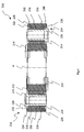
- Fig. 1 1 shows a sectional view of a first embodiment of an elastic joint body 10 with bushings 14 surrounded by a rubber-elastic casing 12.
- the collar components 18, 20, 22 and 24 arranged for the axial support of the loop packages 16 can be seen.
- shaped collar components 18, 20, 22 and 24 are arranged such that their U-shaped cross-section opens in the axial direction of the bushings 14 to the outside.
- the rubber-elastic sheath 12 is preferably connected only to the U-transverse legs of the U-shaped collar components 18, 20, 22 and 24 to avoid the formation of cracks, whereas the side facing away from the sleeve 14 U-longitudinal leg not connected to the rubber-elastic sheath and the can be avoided in the prior art of an outer edge of the collar or similar elements
- the collar components 18, 20, 22 and 24 may have a lower height in the axial direction compared to the prior art.
- the reduction of the height in the axial direction of the collar components 18, 20, 22 and 24 allows the individual loop packs 16 to be enlarged in cross-section in the axial direction can.
- Enlarged loop cross-section packages are synonymous with more turns of thread at the individual loop packages 16, which in accordance with the capacity for torque absorption and at the same time increases the life.
- it can be reduced in the axial direction with the same torque absorption of the elastic joint body 10, ie it can space within a shaft assembly, such. As a powertrain of a vehicle can be saved.
- the manufacturing process of the elastic joint body 10 can be simplified and cost-optimized.
- the rubber-elastic casing is stamped on the U-longitudinal limb in cross-section, d. H.
- the U-shaped collar components 18, 20, 22 and 24 must therefore not be cleaned, resulting in a considerable simplification and acceleration of the manufacturing process.
- the amount of rubber required in the production is reduced, since the rubber scrap, which is obtained in the prior art, is eliminated.
- Fig. 1 can be seen also that the sockets 14 alternately, depending on their connection to (not shown) waves of a shaft assembly or its connection to the drive shaft or output shaft in the axial direction in front of the U-shaped collar components at its end a section D. have enlarged cross-section.
- This section D serves to not transmit to the collar components, in this case 18 and 24, during the screwing of the elastic joint body 10, a torque possibly transmitted to the bush, and also to the U-shaped collar components 16 and 24 additionally support in the axial direction.
- Fig. 2a shows a first embodiment of a U-shaped collar 18, with inner and outer U-longitudinal legs 30 and 32 and extending between them U-transverse legs 34.
- the collar 18 is rotationally symmetrical about its central axis A.
- the inner longitudinal U-leg 30 is slightly shortened compared to the outer U-longitudinal leg 32. Due to the longer design of the outer U-longitudinal leg 32, the vulcanization tool used in the manufacturing process can press on the longer U-longitudinal leg 32 and slightly deform elastically, so that there is a sealing abutment. This can prevent the rubber in the vulcanization process to the socket flows.
- the collar 18 forms a resilient seal with the rubber-elastic sheath, ie, no rubber flows between the collar components 18, 20, 22, 24 during the vulcanization process, or the rubber is displaced by these collar components (FIG. Fig.1 ).
- the loop packages 16 are supported directly by the collar components 18, 20, 22, 24.
- Fig. 2b shows a further embodiment of a U-shaped collar 18, in which the outer U-longitudinal leg 32 is formed not only longer in the axial direction, but also to the axis A of the U-shaped collar 18 has an angle of 5 °.
- Fig. 2c also shows the U-shaped collar 18, in which the angle of inclination of the outer U-longitudinal leg 32 to the axis A of the U-shaped collar is 15 °.
- the inclination angle may be generally selected in a range of 2 to 20 °, preferably in a range of 5 to 15 °.
- the oblique leg 32 of the U-shaped collar has the advantage of improved soil removal as a result of effective in operation centrifugal forces. In addition, it prevents unwanted sliding of individual threads of a loop package, because they can not slide up the slope due to their tension.
- Fig. 2d shows a sectional partial view of another embodiment of a U-shaped collar according to the invention.
- This embodiment is similar to the embodiment according to FIG Figure 2d , but made of plastic. It is latchable via a detent 35, which is arranged on the radially inner surface of the leg 30, on a sleeve formed with a corresponding recess, as is known per se from the prior art.
- Fig. 2e also shows the U-shaped collar 18, in which on the side facing away from the sleeve 14 U-longitudinal leg 32, a further extending from this leg 32 transverse web 37 is provided. Since the rubber-elastic casing 12 does not have to be connected to the longitudinal leg 32, ie can not move from this leg 32 during non-connection during operation, can by the crossbar 37 a very wide opening of the rubber-elastic sheath in the area around the U-shaped longitudinal leg 37 be reduced or completely prevented.
- Fig. 3 shows a sectional view of a second embodiment of the invention, only from the first embodiment according to Fig. 1 characterized in that the bushes 114 do not alternately have a thickened end portion D and the collar components 118, 120, 122 and 124 are pressed directly onto the sockets.
- Fig. 4 11 shows an axially-containing sectional view of a third embodiment of the invention, in which at one axial end of the bushes 214, a collar 218 or 224 is integrally formed integrally on the bushings 214, wherein a U-longitudinal limb 230 is formed by the end region of the bushing 214.
- the U-longitudinal leg 230 is integrally connected to the U-transverse leg 234, which in turn is integrally connected to a remote from the socket U-longitudinal leg 232.
- the U-transverse leg 238 in turn is integrally connected to the U-longitudinal leg 240.
- Fig. 5 shows a fourth embodiment of the invention, which differs from the first embodiment of the invention according to Fig. 1 only differs in that 316 insert discs 342 and 344 are arranged between the individual loop packages.
- the insert discs 342 and 344 serve for the additional axial support of the individual loop packages.
- the shims 342 and 344 are disposed about the bushings 314 for further axial support of the loop assemblies 316 in the area heavily loaded by the cardanic stresses.
- the friction of the individual loop packages 316 can be avoided with each other, ie friction effects of the same material pairings on each other, which can adversely affect the life of the Gelenkgropers 310.
- Fig. 6 shows a fifth embodiment of the invention, in which for further axial support of the loop packages L-shaped collar members 446, 448, 450 and 452 are arranged.
- the L-shaped collar elements 446, 448, 450 and 452 are arranged with their abutting on the bushes 414 section in the direction of the collar components 418, 420, 422 and 424 and in the direction of the end portions of the sockets 414.
- the collar 446, 448, 450, 452 are based on the collar components 418, 420, 422 and 424 and thus form with the collar bodies or between them guideways for axial guidance and support of the loop packages 416 ,
- Fig. 7 shows a sixth embodiment of the invention, in which the U-shaped collar 618 is partially surrounded in an inner region 654 of the rubber-elastic sheath 612.
- Fig. 7 recognizes that remote from the socket 614 U-longitudinal leg 632 according to this embodiment of the invention compared to the voltage applied to the sleeve 614 longitudinal leg 630 shortened. Accordingly, the longitudinal leg 632 is completely surrounded by the rubber-elastic sheath 612.
- the rubber-elastic material in area 654 need not be tied to the U-shaped collar 618 or to the U-longitudinal leg 632 and then, when it is not tethered, can move in the loaded state without cracks occurring in the rubber-elastic sheath 612 , In the unloaded state, ie in the resting state of the joint body 610, moves the rubber-elastic material 612 in the area 654 back to its original position.
- the longitudinal leg 632 acts in this embodiment of the invention together with the rubber-elastic material 612 in the area 654 as a seal against the ingress of dirt and water.
Landscapes
- Engineering & Computer Science (AREA)
- General Engineering & Computer Science (AREA)
- Mechanical Engineering (AREA)
- Vibration Prevention Devices (AREA)
- Support Of The Bearing (AREA)
Description
- Die vorliegende Erfindung betrifft einen elastischen Gelenkkörper für eine Wellenanordnung zum gelenkigen Verbinden zweier Wellenabschnitte mit einer Mehrzahl von Buchsen, die in Umfangsrichtung in vorbestimmten Winkelabständen bezüglich einer Mittelachse des Gelenkkörpers angeordnet sind, einer Mehrzahl von Schlingenpaketen, wobei jedes Schlingenpaket jeweils zwei benachbarte Buchsen umschlingt, und einer gummielastischen Ummantelung, in die die Schlingenpakete und die Buchsen zumindest teilweise eingebettet sind.
- Derartige Gelenkkörper sind aus dem Stand der Technik bekannt und beispielsweise in der deutschen Offenlegungsschrift
DE 37 34 089 A1 offenbart. Dieses Dokument beschreibt in der Beschreibungseinleitung einen elastischen Gelenkkörper, bei dem zur axialen Abstützung der Schlingenpakete in axialer Richtung Kragen aufgepresst sind. Die Kragen weisen ein L-förmiges Profil auf und werden durch das Aufpressen auf je ein Buchsenende axial unverschiebbar und drehfest mit der Buchse verbunden. Zwischen den einzelnen Schlingenpaketen, die die Buchsen umschlingen, sind zur axialen Führung der Schlingenpakete um die Buchsen herum Stützelemente angeordnet. Sowohl die L-förmigen Kragen als auch die Stützelemente werden während eines Vulkanisationsvorgangs mit einer Gummischicht ummantelt. - Im Betrieb des Gelenkkörpers kann es aufgrund von kardanischen Beanspruchungen bzw. Biegebeanspruchungen zu Rissen an der Oberfläche bzw. in der gummielastischen Ummantelung im Bereich einer umlaufenden Aussenkante der L-förmigen Kragen kommen.
- Bei der Montage der Gelenkkörper mit derartigen Kragenelementen in einem Antriebsstrang eines Kraftfahrzeugs kann ferner das durch zur Verschraubung benötigte Drehmoment auf die Kragen übertragen werden, wodurch diese relativ zur angebundenen Gummimasse verdreht werden. Dadurch kann es ebenfalls zu Rissen an der Oberfläche der gummielastischen Ummantelung durch ihre Anbindung an die Kragen kommen. Derartige Risse in der gummielastischen Ummantelung, die im Betrieb oder bereits während der Montage entstehen können, wirken sich negativ auf Lebensdauer des Gelenkkörpers aus.
- Neben den vorangehend beschriebenen Kragenelementen sind zur axialen Abstützung der Schlingenpakete eines elastischen Gelenkkörpers aus dem Stand der Technik auch Ringbleche bekannt, die mit den Buchsen vernietet werden. Bei diesen Ringblechen kann es dazu kommen, dass während des Herstellungsprozesses bzw. des Vulkanisationsvorgangs der Gummi auf die Ringbleche fließt und dort anhaftet. In dem Herstellungsprozess muss deshalb ein zeit- und kostenintensiver Putzvorgang eingeplant werden, um die Ringbleche wieder zu reinigen
- Ferner gehen bei der Entwicklung derartiger Gelenkkörper die Bemühungen auch dahin, die Gelenkkörper im Hinblick auf die durch die stetig steigenden Motorleistungen zunehmenden mechanischen Belastungen auszulegen und deren Lebensdauer weiter zu erhöhen.
- Es ist somit Aufgabe der vorliegenden Erfindung, einen elastischen Gelenkkörper der eingangs bezeichneten Art bereitzustellen, der bei gleicher Dimensionierung den gestiegenen Anforderungen an die Drehmomentübertragung gerecht wird und gleichzeitig eine Erhöhung der Lebensdauer möglich macht, sowie den Herstellungsprozess vereinfacht.
- Diese Aufgabe wird durch einen elastischen Gelenkkörper der eingangs bezeichneten Art gelöst, bei dem an wenigstens einem Endbereich wenigstens einer der Buchsen zur axialen Abstützung eines angrenzenden Schlingenpakets ein um die Buchse umlaufender, zumindest teilweise in die gummielastische Ummantelung eingebetteter Bund vorgesehen ist, der im achsenthaltenden Schnitt betrachtet einen U-förmigen Querschnitt aufweist, wobei der Querschnitt mit zwei U-Längsschenkeln und einem U-Querschenkel ausgebildet ist, wobei der Bund mit einem U-Längsschenkel an der Buchse anliegt.
- Durch die Verwendung eines U-förmigen Bundes bei dem erfindungsgemäßen elastischen Gelenkkörper können Rissbildungen vermieden werden, die sich ausgehend von der äußeren Kante der L-förmigen Kragen an der Oberfläche der gummielastischen Ummantelung bzw. in der gummielastischen Ummantelung bilden und sich negativ auf die Lebensdauer des Gelenkkörpers auswirken können. Die Rissbildung in der gummielastischen Ummantelung kann durch eine abschnittsweise Anbindung des Gummis an die U-förmigen Bund-Bauteile vermieden werden. Mit anderen Worten wird die gummielastische Ummantelung bevorzugt nur an den U-Querschenkel der U-förmigen Bundbauteile angebunden, wodurch die aufgrund von kardanischen Beanspruchungen und während der Montage entstehenden Risse vermieden werden können. Zudem wird der Herstellungsprozess durch den Wegfall von Putzvorgängen und Befestigungsvorgängen, wie z.B. Vernietung der Ringbleche, aufgrund der U-förmigen Bund-Bauteile erheblich verkürzt und weniger kostenintensiv.
- Ein weiterer Vorteil einer Verwendung von U-förmigen Bundbauteilen gegenüber herkömmlichen axialen Abstützungen von Schlingenpaketen besteht darin, dass durch den zusätzlichen U-Längsschenkel das Bundbauteil weiter versteift wird. Dies bedeutet, dass bei einer Belastung der Bundbauteile im Betrieb der Gelenkscheibe, insbesondere durch Angreifen der auf Zug belasteten Schlingenpakete, aufgrund der erhöhten mechanischen Steifigkeit der U-förmigen Bundbauteile deren Lebensdauer und damit die gesamte Lebensdauer des Gelenkkörpers verbessert wird.
- Eine Weiterbildung der Erfindung sieht vor, dass sich der U-förmige Querschnitt des Bundes in Achsrichtung auswärts öffnet.
- Zur Vermeidung von Anlagerungen von Schmutz und zur besseren Abführung von Feuchtigkeit im Bereich der Buchsen bzw. des U-förmigen Bundes sieht eine Weiterbildung der Erfindung vor, dass der von der Buchse abgewandte U-Längsschenkel in einem vorbestimmten Winkel zur Achse der Buchse geneigt ist. In diesem Zusammenhang kann vorgesehen sein, dass der Winkel in einem Bereich von 2 bis 20°, vorzugsweise von 5-15° gewählt werden kann. Mit anderen Worten, können durch die Neigung des von der Buchse abgewandten U-Längsschenkels aufgrund der im Betrieb des Gelenkkörpers wirkenden Zentrifugalkräfte Schmutz und Feuchtigkeit von den Buchsen bzw. U-förmigen Bundbauteilen schnell und einfach abgeführt werden. Ein weiterer Vorteil der schrägen Ausbildung des von der Buchse abgewandten U-Längsschenkels besteht darin, dass durch den schrägen Verlauf verhindert wird, dass einzelne oder mehrere Schlingen eines Schlingenpakets bei der Herstellung des Gelenkkörpers über den Bund abrutschen können. Wird ein entsprechend schräg ausgebildetes U-förmiges Bundbauteil verwendet, so werden aufgrund der Schräge einzelne Schlingen eines Schlingenpakets daran gehindert, über den Bund abzurutschen, weil sie nicht entgegen ihrer Spannung die Schräge empor gleiten können.
- Gemäß einer bevorzugten Ausführungsform der Erfindung kann der Bund als separates Bauteil ausgebildet und auf die Buchse aufgepresst oder aufgerastet werden. Ein Aufrasten empfiehlt sich insbesondere bei der Verwendung von U-förmigen Bundbauteilen aus Kunststoff, die auf eine entsprechende Buchse aufgerastet werden. Dies ist bereits aus dem Stand der Technik für L- förmige Bundbuchsen bekannt.
- Zur Vereinfachung des Herstellungsprozesses sieht eine Weiterbildung der Erfindung vor, dass der an der Buchse anliegende U-Längsschenkel in axialer Richtung kürzer ausgebildet ist, als der von der Buchse abgewandte U-Längsschenkel. Während des Vulkanisationsvorgangs kann die Form auf den radial äußeren längeren Schenkel drücken und diesen elastisch in axialer Richtung eindrücken. Dadurch bilden die aneinander anliegenden Flächen von Form und U-förmigem Bund-Bauteil eine dichtende Anlage, so dass kein Gummi in Richtung der Buchse fließen kann. Zudem kann der Gummi bei der Vulkanisation an dem äußeren, längeren U-Längsschenkel abgeprägt werden. Mit anderen Worten, läuft der Gummi nicht wie bei herkömmlichen Ringblechen oder ähnlichen Elementen zur axialen Abstützung der Schlingenpakete auf diese Elemente. Dieser unerwünschte buchsennahe Gummiüberschuss muss erfindungsgemäß nicht mehr wie beim Stand der Technik durch aufwändige und zeitintensive Putzvorgänge entfernt werden, da bei dem erfindungsgemäßen Gelenkkörper mit U-förmigem Bund kein Gummi über den äußeren, längeren U-Längsschenkel in die U-Form des Bundes läuft. Ferner kann durch den äußeren, längeren U-Längsschenkel das genutzte Vulkanisationswerkzeug vereinfacht werden, da der U-Längsschenkel zur Vorzentrierung genutzt werden kann.
- Zusätzlich zur vorangestellt beschriebenen Ausbildung des Bundes als separates Bauteil, das auf die Buchsen aufgepresst wird, kann gemäß einer bevorzugten Ausführungsform der Erfindung der Bund an einem Ende der Buchse integral angeformt sein, wobei der Endbereich der Buchse einen U-Längsschenkel bildet, der mit einem U-Querschenkel integral verbunden ist, welcher wiederum mit einem von der Buchse abgewandeten U-Längsschenkel integral verbunden ist. In diesem Zusammenhang bleibt zu erwähnen, dass an dem anderen Endabschnitt der Buchse ein Bund als separates Bauteil angebracht werden kann. Mit anderen Worten kann eine Buchse, die mit einem integral ausgebildeten Bund an ihrem einen Endbereich an ihrem anderen axialen Endbereich mit einem separaten Bund-Bauteil versehen werden, das auf diesen Endbereich aufgepresst wird. Die Buchsen mit integral ausgebildeten Bundbauteilen werden wechselweise mit den separaten Bundbauteilen an den beiden axialen Oberflächen der gummielastischen Ummantelung angebracht. Durch die Buchsen mit integralen Bundbauteilen kann der Herstellungsprozess weiter verkürzt werden, da an einem Endbereich einer Buchse der Aufpressvorgang für den Bund entfällt.
- Vorangehend wurde bereits beschrieben, dass während des Vulkanisationsvorgangs der Gummi an dem äußeren, längeren U-Längsschenkel abgeprägt wird. Deshalb sieht eine Weiterbildung der Erfindung vor, dass die gummielastische Ummantelung den Bund im Bereich seines von der Buchse abgewandten U-Längsschenkels bis zu dessen axial äußeren Rand umgibt, wobei eine axial äußere Umfangsfläche des von der Buchse abgewandeten U-Längsschenkels mit der Oberfläche der elastischen Ummantelung im wesentlichen bündig abschließt. Durch diesen bündigen Abschluss bzw. durch das Eindrücken des Bundes in die gummielastische Ummantelung während der Vulkanisation, bildet der Bund gemäß einer Ausführungsform der Erfindung mit der gummielastischen Ummantelung eine nachgiebige Abdichtung, da der U-förmige Bund den flüssigen Gummi während der Vulkanisation verdrängt und der Bund sozusagen "einfedert".
- Zur weiteren axialen Abstützung bzw. axialen Führung der um eine Buchse verlaufenden Schlingenpakete, sieht eine Weiterbildung der Erfindung vor, dass zwischen zwei jeweils an den Endabschnitten einer Buchse angeordneten Bund-Bauteilen zusätzlich Kragen oder Einlagescheiben zur axialen Abstützung einzelner dazwischen liegender Schlingenpakete vorgesehen sind. Diese zusätzlichen Einlagescheiben und Kragen verhindern unerwünschte Reibungswirkungen zwischen den Schlingenpaketen und stützen diese gerade im besonders stark beanspruchten Bereich um die Buchsen axial ab, wodurch die Lebensdauer und die Drehmomentaufnahme weiter erhöht werden kann.
- Da der Gummi an dem von der Buchse abgewandten U-Längsschenkel nicht angebunden sein muss, kann erfindungsgemäß zur Vermeidung von Rissen in der gummielastischen Ummantelung an dem von der Buchse abgewandten U-Längsschenkel ein Quersteg vorgesehen sein. Mit diesem zusätzlichen Quersteg an dem von der Buchse abgewandten U-Längsschenkel, d.h. am Außenumfang des U-förmigen Bundes, kann die Gefahr eines Aufklaffens des unangebundenen gummielastischen Materials weiter reduziert oder vollständig unterbunden werden, wodurch ein Eindringen von Schmutz und Feuchtigkeit in den Gelenkkörper verhindert wird.
- Gemäß einer weiteren Ausführungsform der Erfindung kann der von der Buchse abgewandte U-Längsschenkel von der gummielastischen Ummantelung umgeben sein. Mit anderen Worten ist der U-förmige Bund zumindest teilweise mit Gummi umspritzt. Das den von der Buchse abgewandten U-Längsschenkel umgebende gummielastische Material wird nicht an das Bund-Bauteil angebunden und kann sich deshalb je nach Belastungszustand des Gelenkkörpers bewegen, ohne die Gefahr einer Rissbildung. Bei Übergang in den Ruhezustand des Gelenkkörpers bewegt sich das gummielastische Material wieder in die Ausgangsposition zurück. Ferner verhindert hier das gummielastische Material, das den von der Buchse abgewandten U-Längsschenkel umgibt, das Eindringen von Schmutz und Wasser in den Gelenkkörper.
- Hinsichtlich der Materialwahl für die Bund-Bauteile sind diese gemäß einer bevorzugten Ausführungsform aus Metall oder Kunststoff hergestellt.
- Eine Weiterbildung der Erfindung sieht vor, dass die gummielastische Ummantelung zumindest abschnittsweise an den Bund angebunden ist. Durch die abschnittsweise Anbindung der Bund-Bauteile an die gummielastische Ummantelung kann die Abstützung der Schlingenpakete beeinflusst und vorteilhaft auf die Vermeidung von Rissbildungen eingewirkt werden.
- Die Erfindung betrifft ferner eine Wellenanordnung mit einem erfindungsgemäßen Gelenkkörper.
- Die Erfindung wird im Folgenden beispielhaft anhand der beiliegenden Figuren erläutert. Es stellen dar:
- Fig. 1
- eine achsenthaltende Schnittansicht einer ersten Ausführungsform der Erfindung;
- Fig. 2a, 2b,2c, 2d, 2e
- Querschnittsansichten eines Bundes mit verschiedenen Neigungswinkeln des von der Buchse abgewandten U-Längsschenkels;
- Fig. 3
- eine achsenthaltende Schnittansicht einer zweiten Ausführungsform der Erfindung;
- Fig. 4
- eine achsenthaltende Schnittansicht einer dritten Ausführungsform der Erfindung;
- Fig. 5
- eine achsenthaltende Schnittansicht einer vierten Ausführungsform der Erfindung;
- Fig. 6
- eine achsenthaltende Schnittansicht einer fünften Ausführungsform der Erfindung; und
- Fig. 7
- eine aufgebrochene Schnittansicht einer sechsten Ausführungsform der Erfindung
-
Fig. 1 zeigt eine Schnittansicht einer ersten Ausführungsform eines elastischen Gelenkkörpers 10 mit von einer gummielastischen Ummantelung 12 umgebenen Buchsen 14. An den Endbereichen der Buchsen 14 erkennt man die zur axialen Abstützung der Schlingenpakete 16 angeordneten Bund-Bauteile 18, 20, 22 und 24. Die U-förmigen Bund-Bauteile 18, 20, 22 und 24 sind derart angeordnet, dass sich ihr U-förmiger Querschnitt in Achsrichtung der Buchsen 14 nach außen öffnet. - Auf die Geometrie der Bund-Bauteile 18, 20, 22 und 24 wird mit Bezug auf die
Fig. 2a, 2b, 2c, 2d und 2e detailliert eingegangen. - Aus
Fig. 1 erkennt man zudem, dass die U-förmigen Bund-Bauteile 18, 20, 22 und 24 bzw. der von der Buchse 14 abgewandte U-Längsschenkel im wesentlichen bündig mit den Oberflächen 26 und 28 der gummielastischen Ummantelung 12 abschließt, d. h. die U-förmigen Bundbauteile sind in die gummielastische Ummantelung eingebettet. Durch die U-förmigen Bund-Bauteile 18, 20, 22 und 24 werden Risse in der gummielastischen Ummantelung 12 aufgrund von kardanischen Beanspruchungen oder von während der Montage auf die Buchsen 14 übertragenen Drehmomenten vermieden, da im Gegensatz zum Stand der Technik die Bundbauteile 18, 20, 22 und 24 nicht vollständig an die gummielastische Ummantelung 12 angebunden werden bzw. vollständig ummantelt sind. Die gummielastischen Ummantelung 12 ist zur Vermeindung der Rissbildung bevorzugt nur an den U-Querschenkel der U-förmigen Bund-Bauteile 18, 20, 22 und 24 angebunden, wohingegen der von der Buchse 14 abgewandte U-Längsschenkel nicht an die gummielastische Ummantelung angebunden und die beim Stand der Technik von einer äußeren Kante der Kragen oder ähnlichen Elementen vermieden werden können - Durch die Vermeidung von Rissen in der gummielastischen Ummantelung 12 können die Bund-Bauteile 18, 20, 22 und 24 verglichen mit dem Stand der Technik eine geringere Höhe in axialer Richtung aufweisen können. Die Verringerung der Höhe in axialer Richtung der Bundbauteile 18, 20, 22 und 24 ermöglicht, dass die einzelnen Schlingenpakete 16 in axialer Richtung im Querschnitt vergrößert ausgelegt werden können. Im Querschnitt vergrößerte Schlingenpakete sind gleichbedeutend mit mehr Fadenwindungen an den einzelnen Schlingenpaketen 16, wodurch entsprechend die Kapazität zur Drehmomentaufnahme und gleichzeitig die Lebensdauer erhöht wird. Alternativ hierzu kann bei gleicher Drehmomentaufnahme der elastische Gelenkkörper 10 in axialer Richtung verkleinert werden, d. h. es kann Bauraum innerhalb einer Wellenanordnung, wie z. B. einem Antriebsstrang eines Fahrzeugs, eingespart werden.
- Durch die U-Form der Bund-Bauteile 18, 20, 22 und 24 kann ferner der Herstellungsprozess des elastischen Gelenkkörpers 10 vereinfacht und kostenoptimiert werden. Im Herstellungsprozess bzw. des Vulkanisationsvorgangs wird die gummielastische Ummantelung an dem im Querschnitt äußeren U-Längsschenkel abgeprägt, d. h. es gelangt kein überschüssiger Gummi in die U-Form der Bund-Bauteile 18, 20, 22 und 24. Die U-förmigen Bund-Bauteile 18, 20, 22 und 24 müssen somit nicht mehr geputzt werden, was zu einer erheblichen Vereinfachung und Beschleunigung des Herstellungsprozesses führt. Damit einhergehend wird die bei der Herstellung benötigte Gummimenge reduziert, da der Gummiausschuss, der bei dem Stand der Technik anfällt, entfällt.
- Aus
Fig. 1 erkennt man zudem, dass die Buchsen 14 wechselweise, abhängig von ihrer Anbindung an (nicht gezeigte) Wellen einer Wellenanordnung bzw. ihrer Anbindung an die Antriebswelle oder Abtriebswelle, in axialer Richtung vor den U-förmigen Bund-Bauteilen an ihrem Ende einen Abschnitt D mit vergrößertem Querschnitt aufweisen. Dieser Abschnitt D dient dazu, bei der Verschraubung des elastischen Gelenkkörpers 10 ein möglicherweise auf die Buchse übertragenes Drehmoment nicht auf die Bund-Bauteile, in diesem Fall 18 und 24, zu übertragen, und auch dazu, die U-förmigen Bund-Bauteile 16 und 24 in axialer Richtung zusätzlich abzustützen. -
Fig. 2a zeigt ein erstes Ausführungsbeispiel eines U-förmigen Bundes 18, mit inneren und äußeren U-Längsschenkeln 30 und 32 und sich zwischen diesen erstreckenden U-Querschenkeln 34. Der Bund 18 ist rotationssymmetrisch um seine Mittelachse A. Zudem erkennt man ausFig. 2a , dass der innere U-Längsschenkel 30 verglichen mit dem äußeren U-Längsschenkel 32 leicht verkürzt ausgebildet ist. Durch die längere Ausbildung des äußeren U-Längsschenkels 32 kann das im Herstellungsprozess verwendete Vulkanisationswerkzeug auf den längeren U-Längsschenkel 32 drücken und diesen leicht elastisch deformieren, so dass sich eine dichtende Anlage ergibt. Dadurch kann verhindert werden, dass der Gummi im Vulkanisationsvorgang zur Buchse fließt. Ferner kann durch diesen U-Längsschenkel 32 eine Vorzentrierung im Werkzeug erfolgen kann. Der Bund 18 bildet mit der gummielastischen Ummantelung eine nachgiebige Abdichtung, d. h. es fließt während des Vulkanisationsvorgangs kein Gummi zwischen die Bund-Bauteile 18, 20, 22 , 24 bzw. der Gummi wird durch diese Bund-Bauteile verdrängt (Fig.1 ). Somit werden die Schlingenpakete 16 direkt durch die Bund-Bauteile 18, 20, 22 , 24 abgestützt. -
Fig. 2b zeigt ein weiteres Ausführungsbeispiel für einen U-förmigen Bund 18, bei dem der äußere U-Längsschenkel 32 nicht nur in axialer Richtung länger ausgebildet ist, sondern auch zur Achse A des U-förmigen Bundes 18 einen Winkel von 5° aufweist. -
Fig. 2c zeigt ebenfalls den U-förmigen Bund 18, bei dem der Neigungswinkel des äußeren U-Längsschenkels 32 zur Achse A des U-förmigen Bundes 15° beträgt. Der Neigungswinkel kann allgemein in einem Bereich von 2 bis 20° gewählt werden, vorzugsweise in einem Bereich von 5 bis 15°. Der schräg verlaufende Schenkel 32 des U-förmigen Bundes hat den Vorteil einer verbesserten Schmutzabführung in Folge von im Betrieb wirksamen Zentrifugalkräften. Darüber hinaus verhindert er ein unerwünschtes Abgleiten einzelner Fäden eines Schlingenpakets, weil diese aufgrund ihrer Spannung nicht an der Schräge empor gleiten können. -
Fig. 2d zeigt eine geschnittene Teilansicht einer weiteren Ausführungsform eines U-förmigen Bunds gemäß der Erfindung. Diese Ausführungsform ist ähnlich der Ausführungsform gemäßFigur 2d , jedoch aus Kunststoff ausgebildet. Sie ist über eine Rastnase 35, die an der radial inneren Oberfläche des Schenkels 30 angeordnet ist, auf eine mit einer entsprechenden Ausnehmung ausgebildete Buchse aufrastbar, wie dies aus dem Stand der Technik an sich bekannt ist. - Bei den Ausführungsbeispielen für den Bund 18 gemäß der
Figuren 2b und 2c können durch die Neigung des äußeren U-Längsschenkels 32 Schmutz und Feuchtigkeit aufgrund der im Betrieb einer Wellenanordnung wie z.B. dem Antriebsstrang eines Fahrzeugs wirkenden Zentrifugalkräfte schnell aus dem Bereich der Buchsen bzw. des U-förmigen Bundes 18 abgeführt werden. Der sich negativ auf die Lebensdauer auswirkende Einfluss von Verschmutzungen bzw. von Feuchtigkeit kann somit weitestgehend unterbunden werden. -
Fig. 2e zeigt ebenfalls den U-förmigen Bund 18, bei dem an dem von der Buchse 14 abgewandten U-Längsschenkel 32 ein weiterer sich von diesem Schenkel 32 erstreckender Quersteg 37 vorgesehen ist. Da die gummielastische Ummantelung 12 an dem Längsschenkel 32 nicht angebunden sein muss, d.h. bei Nicht-Anbindung sich im Betrieb von diesem Schenkel 32 entfernen kann, kann durch den Quersteg 37 ein sehr weites Aufklaffen der gummielastischen Ummantelung in dem Bereich um den U-förmigen Längsschenkel 37 reduziert oder vollständig unterbunden werden. - Im Folgenden werden mit Bezug auf die weiteren Figuren weitere Ausführungsbeispiele der Erfindung erläutert. Zur Vermeidung von Wiederholungen und zur Vereinfachung der Beschreibung werden für gleichwirkende oder gleichartige Komponenten dieselben Bezugszeichen verwendet, wie im ersten Ausführungsbeispiel, jedoch mit einer fortlaufenden Ziffer vorangestellt.
-
Fig. 3 zeigt eine Schnittansicht einer zweiten Ausführungsform der Erfindung, die sich lediglich von der ersten Ausführungsform gemäßFig. 1 dadurch unterscheidet, dass die Buchsen 114 nicht wechselweise einen verdickten Endabschnitt D aufweisen und die Bund-Bauteile 118, 120, 122 und 124 direkt auf die Buchsen aufgepresst sind. -
Fig. 4 zeigt eine achsenthaltende Schnittansicht einer dritten Ausführungsform der Erfindung, bei der an einem axialen Ende der Buchsen 214 ein Bund 218 bzw. 224 integral an den Buchsen 214 angeformt ist, wobei ein U-Längsschenkel 230 von dem Endbereich der Buchse 214 gebildet wird. Der U-Längsschenkel 230 ist integral mit dem U-Querschenkel 234 verbunden, der wiederum mit einem von der Buchse abgewandten U-Längsschenkel 232 integral verbunden ist. Gleiches gilt für den Bund 224 mit dem von der Buchse gebildeten U-Längsschenkel 236, der integral mit dem U-Längsschenkel 238 verbunden ist. Der U-Querschenkel 238 wiederum ist mit dem U-Längsschenkel 240 integral verbunden. - Zudem erkennt man aus
Fig. 4 , dass an dem von dem integral an der Buchse ausgebildeten Bund abgewandten axialen Ende der Buchse 214 ein separater Bund 220 aufgepresst ist, gleiches gilt für den Bund 222. Durch Anordnung von Buchsen 214 mit integralen Bundbauteilen 218 und 224 kann der Herstellungsprozess beschleunigt werden, da an einem Endbereich einer Buchse der Aufpressvorgang für eines der Bund-Bauteile entfällt. -
Fig. 5 zeigt eine vierte Ausführungsform der Erfindung, die sich von der ersten Ausführungsform der Erfindung gemäßFig. 1 lediglich darin unterscheidet, dass zwischen den einzelnen Schlingenpaketen 316 Einlagescheiben 342 bzw. 344 angeordnet sind. Die Einlagescheiben 342 und 344 dienen zur zusätzlichen axialen Abstützung der einzelnen Schlingenpakete. Die Einlagescheiben 342 und 344 sind zur weiteren axialen Abstützung bzw. Führung der Schlingenpakete 316 im durch die kardanischen Beanspruchungen stark belasteten Bereich um die Buchsen 314 herum angeordnet. Zudem kann durch die Einlagescheiben 342 und 344 die Reibung der einzelnen Schlingenpakete 316 untereinander vermieden werden, d.h. Reibungswirkungen von gleichen Materialpaarungen aufeinander, die sich negativ auf die Lebensdauer des Gelenkköpers 310 auswirken können. -
Fig. 6 zeigt eine fünfte Ausführungsform der Erfindung, bei der zur weiteren axialen Abstützung der Schlingenpakete L-förmige Kragenelemente 446, 448, 450 und 452 angeordnet sind. Die L-förmigen Kragenelemente 446, 448, 450 und 452 sind mit ihrem an den Buchsen 414 anliegenden Abschnitt in Richtung der Bund-Bauteile 418, 420, 422 und 424 bzw. in Richtung der Endabschnitte der Buchsen 414 angeordnet. Mit ihrem an den Buchsen anliegenden Abschnitt stützen sich die Kragen 446, 448, 450, 452 an den Bund-Bauteilen 418, 420, 422 und 424 ab und bilden somit mit den Bundkörpern bzw. zwischen ihnen Führungsbahnen zur axialen Führung und Abstützung der Schlingenpakete 416. - Für die Ausführungsform gemäß
Fig. 6 gilt das mit Bezug aufFig. 5 gesagte, dass die Kragen 446, 448, 450, 452 zur axialen Abstützung und zur Vermeindung von Reibungswirkungen zwischen den einzelnen Schlingenpaketen 416 angeordnet werden. -
Fig. 7 zeigt eine sechste Ausführungsform der Erfindung, bei der der U-förmige Bund 618 in einem inneren Bereich 654 von der gummielastischen Ummantelung 612 teilweise umgeben ist. Wie man ausFig. 7 erkennt, ist der von der Buchse 614 abgewandte U-Längsschenkel 632 gemäß dieser Ausführungsform der Erfindung verglichen mit dem an der Buchse 614 anliegenden Längsschenkel 630 verkürzt ausgebildet. Dementsprechend ist der Längsschenkel 632 vollständig von der gummielastischen Ummantelung 612 umgeben. Das gummielastische Material im Bereich 654 muss nicht an dem U-förmigen Bund 618 bzw. an dem U-Längsschenkel 632 angebunden sein und kann sich dann, wenn es nicht angebunden ist, im belasteten Zustand bewegen, ohne dass Risse in der gummielastischen Ummantelung 612 auftreten. Im unbelasteten Zustand, d.h. im Ruhezustand des Gelenkkörpers 610, bewegt sich das gummielastische Material 612 im Bereich 654 wieder zurück in seine Ausgangsposition. Der Längsschenkel 632 wirkt in dieser Ausführungsform der Erfindung zusammen mit dem gummielastischen Material 612 im Bereich 654 als Abdichtung gegen das Eindringen von Schmutz und Wasser. Abgesehen von der vorstehend beschriebenen Möglichkeit zur Abdichtung am äußeren U-Längsschenkel bei der Herstellung können bei dieser Ausführungsform alle Vorteile der vorstehend beschriebenen Ausführungsform erreicht werden.
Claims (16)
- Elastischer Gelenkkörper (10) für eine Wellenanordnung zum gelenkigen Verbinden zweier Wellenabschnitte mit- einer Mehrzahl von Buchsen (14), die in Umfangsrichtung in vorbestimmten Winkelabständen bezüglich einer Mittelachse (M) des Gelenkkörpers (10) angeordnet sind,- einer Mehrzahl von Schlingenpaketen (16), wobei jedes Schlingenpaket (16) jeweils zwei benachbarte Buchsen (14) umschlingt, und- einer gummielastischen Ummantelung (12), in die die Schlingenpakete (16) und die Buchsen (14) zumindest teilweise eingebettet sind, wobeian wenigstens einem Endbereich wenigstens einer der Buchsen (14) zur axialen Abstützung eines angrenzenden Schlingenpakets (16) ein um die Buchse (14) umlaufender, zumindest teilweise in die gummielastische Ummantelung (12) eingebetteter Bund (18, 20, 22, 24; 218, 224) vorgesehen ist, der im achsenthaltenden Schnitt betrachtet einen U- förmigen Querschnitt aufweist, wobei der Querschnitt mit zwei U-Längsschenkeln (30, 32) und einem U- Querschenkel (34) ausgebildet ist, dadurch gekennzeichnet, dass der Bund mit einem U-Längsschenkel (30, 32) an der Buchse (14) anliegt.
- Gelenkkörper (10) nach Anspruch 1,
dadurch gekennzeichnet, dass sich der U-förmige Querschnitt des Bunds (18, 20, 22, 24; 218, 224) in Achsrichtung auswärts öffnet. - Gelenkkörper (10) nach Anspruch 1 oder 2,
dadurch gekennzeichnet, dass der von der Buchse (14) abgewandte U-Längsschenkel (32) in einem vorbestimmten Winkel zur Achse der Buchse geneigt ist. - Gelenkkörper (10) nach Anspruch 3,
dadurch gekennzeichnet, dass der Winkel in einem Bereich von 2 bis 20°, vorzugsweise von 5 bis 15°, liegt. - Gelenkkörper (10) nach einem der vorangehenden Ansprüche,
dadurch gekennzeichnet, dass der Bund (18, 20, 22, 24) als separates Bauteil ausgebildet und auf die Buchse (14) aufgepresst oder aufgerastet ist. - Gelenkkörper (10) nach Anspruch 5,
dadurch gekennzeichnet, dass der an der Buchse (14) anliegende U-Längsschenkel (30) in axialer Richtung kürzer ausgebildet ist, als der von der Buchse (14) abgewandte U-Längsschenkel (32). - Gelenkkörper (210) nach einem der vorangehenden Ansprüche,
dadurch gekennzeichnet, dass an einem Ende der Buchse (214) ein Bund (218, 224) integral angeformt ist, wobei der Endbereich der Buchse (214) einen U-Längsschenkel (230, 236) bildet, der mit einem U-Querschenkel (232, 238) integral verbunden ist, welcher wiederum mit einem von der Buchse (214) abgewandten U-Längsschenkel (234, 240) integral verbunden ist. - Gelenkkörper (210) nach Anspruch 7,
dadurch gekennzeichnet, dass an dem anderen Endabschnitt der Buchse (214) ein Bund (220, 222) als separates Bauteil angebracht. - Gelenkkörper (10) nach einem der vorangehenden Ansprüche,
dadurch gekennzeichnet, dass die gummielastische Ummantelung (12) den Bund (18, 20, 22, 24) im Bereich seines von der Buchse (14) abgewandten U-Längsschenkels (32) bis zu dessen axial äußeren Rand umgibt, wobei eine axial äu-βere Umfangsfläche des von der Buchse (14) abgewandten U-Längsschenkels (32) mit der Oberfläche (26, 28) der elastischen Ummantelung (12) im wesentlichen bündig abschließt. - Gelenkkörper (10) nach einem der vorangehenden Ansprüche,
dadurch gekennzeichnet, dass der Bund (10, 20, 22, 24) mit der gummielastischen Ummantelung (12) eine nachgiebige Abdichtung bildet. - Gelenkkörper (310; 410) nach einem der vorangehenden Ansprüche,
dadurch gekennzeichnet, dass zwischen zwei jeweils an den Endabschnitten einer Buchse (214;410) angeordneten Bund-Bauteilen (318, 320, 322, 324; 418, 420, 422, 424) Kragen (446, 448, 450, 452) oder Einlagescheiben (342, 344) zur axialen Abstützung einzelner dazwischen liegender Schlingenpakete vorgesehen sind. - Gelenkkörper (10) nach einem der vorangehenden Ansprüche,
dadurch gekennzeichnet, dass an dem von der Buchse (14) abgewandten U-Längsschenkel (32) ein Quersteg (37) vorgesehen ist. - Gelenkkörper (610) nach einem der vorangehenden Ansprüche,
dadurch gekennzeichnet, dass der von der Buchse (614) abgewandte U-Längsschenkel (632) von der gummielastischen Ummantelung (612) umgeben ist. - Gelenkkörper (10) nach einem der vorangehenden Ansprüche,
dadurch gekennzeichnet, dass der Bund (18, 20, 22, 24) aus Metall oder Kunststoff hergestellt ist. - Gelenkkörper (10) nach einem der vorangehenden Ansprüche,
dadurch gekennzeichnet, dass die gummielastische Ummantelung (12) zumindest abschnittsweise an den Bund (18, 20, 22, 24) angebunden verbunden ist. - Wellenanordnung mit einem Gelenkkörper (10) nach einem der Ansprüche 1 bis 15.
Applications Claiming Priority (2)
| Application Number | Priority Date | Filing Date | Title |
|---|---|---|---|
| DE102008026763A DE102008026763A1 (de) | 2008-06-05 | 2008-06-05 | Elastischer Gelenkkörper |
| PCT/EP2009/003832 WO2009146844A1 (de) | 2008-06-05 | 2009-05-28 | Elastischer gelenkkörper |
Publications (2)
| Publication Number | Publication Date |
|---|---|
| EP2283245A1 EP2283245A1 (de) | 2011-02-16 |
| EP2283245B1 true EP2283245B1 (de) | 2011-12-28 |
Family
ID=40929641
Family Applications (1)
| Application Number | Title | Priority Date | Filing Date |
|---|---|---|---|
| EP09757227A Active EP2283245B1 (de) | 2008-06-05 | 2009-05-28 | Elastischer gelenkkörper |
Country Status (6)
| Country | Link |
|---|---|
| US (1) | US8469828B2 (de) |
| EP (1) | EP2283245B1 (de) |
| AT (1) | ATE539272T1 (de) |
| DE (1) | DE102008026763A1 (de) |
| ES (1) | ES2378034T3 (de) |
| WO (1) | WO2009146844A1 (de) |
Families Citing this family (7)
| Publication number | Priority date | Publication date | Assignee | Title |
|---|---|---|---|---|
| DE102010046673B4 (de) | 2010-09-27 | 2020-07-30 | Süddeutsche Gelenkscheibenfabrik Gesellschaft mit beschränkter Haftung & Co. KG | Elastischer Gelenkkörper mit schlingenschonender Bundbuchsenanordnung |
| DE102011012922A1 (de) * | 2011-03-03 | 2012-09-06 | SGF SüDDEUTSCHE GELENKSCHEIBENFABRIK GMBH & CO. KG | Verfahren zum Herstellen eines elastischen Kraftübertragungsglieds und elastisches Kraftübertragungsglied |
| DE102012012974B4 (de) | 2012-06-28 | 2024-02-08 | FlexCon Germany GmbH | Elastisches Drehverbindungselement, insbesondere elastische Torsionskupplung oder elastische Gelenkscheibe, sowie Verfahren zu dessen Herstellung |
| ITVR20120245A1 (it) | 2012-12-19 | 2014-06-20 | Tumedei S P A | Composition for a disc-type flexible coupling and coupling including such composition. - composizione per un giunto flessibile del tipo a disco e giunto includente tale composizione. |
| DE202013001278U1 (de) * | 2013-02-08 | 2013-02-22 | SGF SüDDEUTSCHE GELENKSCHEIBENFABRIK GMBH & CO. KG | Elastischer Gelenkkörper mit bauraumsparender Bundbuchsenanordnung |
| DE202015003886U1 (de) * | 2015-05-28 | 2015-06-12 | Süddeutsche Gelenkscheibenfabrik GmbH & Co. KG | Elastischer Gelenkkörper |
| DE102019130272A1 (de) * | 2019-11-10 | 2021-05-12 | Boge Elastmetall Gmbh | Elastische Kupplung |
Family Cites Families (12)
| Publication number | Priority date | Publication date | Assignee | Title |
|---|---|---|---|---|
| US1753985A (en) * | 1926-02-18 | 1930-04-08 | Flintermann Gerhard | Flexible joint |
| FR837975A (fr) * | 1937-05-19 | 1939-02-23 | Perfectionnements apportés aux joints flexibles ou élastiques notamment pour des arbres de transmission | |
| GB497903A (en) * | 1938-05-26 | 1938-12-30 | Hardy Spicer & Co Ltd | Flexible coupling discs |
| JPS51143158A (en) * | 1975-06-04 | 1976-12-09 | Toyota Motor Corp | Flexible coupling for power transmission |
| JPS551067A (en) | 1979-02-27 | 1980-01-07 | Tokyo Shibaura Electric Co | Method of manufacturing synthetic resin molded device |
| JPS5635539Y2 (de) * | 1979-04-24 | 1981-08-21 | ||
| JPH0752427Y2 (ja) | 1986-11-07 | 1995-11-29 | 東洋ゴム工業株式会社 | 高負荷トルク伝達用弾性継手 |
| JPH0733852B2 (ja) * | 1989-09-07 | 1995-04-12 | 東海ゴム工業株式会社 | カップリング |
| DE3942432C1 (en) | 1989-12-21 | 1991-05-23 | Sgf Sueddeutsche Gelenkscheibenfabrik Gmbh & Co Kg, 8264 Waldkraiburg, De | Swivel joint coupling for vehicle drive shaft - includes rubber core with rigid sleeves through which fixing bolts pass |
| DE19630780A1 (de) * | 1996-07-31 | 1998-02-05 | Freudenberg Carl Fa | Kupplung |
| JPH11325101A (ja) | 1998-05-15 | 1999-11-26 | Nok Megulastik Co Ltd | カップリング |
| JP3680780B2 (ja) * | 2001-10-11 | 2005-08-10 | 東洋ゴム工業株式会社 | 弾性継手 |
-
2008
- 2008-06-05 DE DE102008026763A patent/DE102008026763A1/de not_active Withdrawn
-
2009
- 2009-05-28 WO PCT/EP2009/003832 patent/WO2009146844A1/de not_active Ceased
- 2009-05-28 US US12/996,204 patent/US8469828B2/en not_active Expired - Fee Related
- 2009-05-28 AT AT09757227T patent/ATE539272T1/de active
- 2009-05-28 ES ES09757227T patent/ES2378034T3/es active Active
- 2009-05-28 EP EP09757227A patent/EP2283245B1/de active Active
Also Published As
| Publication number | Publication date |
|---|---|
| DE102008026763A1 (de) | 2009-12-17 |
| EP2283245A1 (de) | 2011-02-16 |
| ATE539272T1 (de) | 2012-01-15 |
| US20110190067A1 (en) | 2011-08-04 |
| WO2009146844A1 (de) | 2009-12-10 |
| ES2378034T3 (es) | 2012-04-04 |
| US8469828B2 (en) | 2013-06-25 |
Similar Documents
| Publication | Publication Date | Title |
|---|---|---|
| EP1995088B1 (de) | Einsatzlagerteil, elastisches Einsatzlager und Federbeinlageranordnung | |
| DE3431460A1 (de) | Fluidgefuellte federnde buchsenkonstruktion | |
| DE102008013576B4 (de) | Torsionsschwingungsdämpfer, insbesondere für den Antriebsstrang eines Fahrzeugs | |
| WO2009146844A1 (de) | Elastischer gelenkkörper | |
| DE102019113847B3 (de) | Lageranordnung | |
| DE102018211377B4 (de) | Rotorträger für eine elektrische Maschine | |
| EP1270987A2 (de) | Aggregatelager in Buchsenform | |
| DE102008050202A1 (de) | Elastischer Gelenkkörper | |
| DE112015001500B4 (de) | Antriebskraft-Übertragungsvorrichtung und ein Herstellungsverfahren für diese Vorrichtung | |
| DE19601290C2 (de) | Kreuzgelenkanordnung für eine Gelenkwelle | |
| WO2004092612A1 (de) | Hydraulisch dämpfendes gummibuchsenlager für vertikale montage | |
| DE69826787T2 (de) | Kardanwelle | |
| DE102015010195A1 (de) | Kupplungsvorrichtung | |
| DE102014007798B4 (de) | Buchsenanordnung zur Zentrierung zweier zu verbindender Wellenabschnitte | |
| DE102008062305A1 (de) | Vorrichtung zum schwingungsgedämpften Übertragen von Drehmomenten sowie Buchsenanordnung hierfür und Verfahren zum Herstellen einer solchen Vorrichtung | |
| EP0958461B1 (de) | Wellenkupplung mit kühlelementen | |
| DE202011108594U1 (de) | Elastischer Gelenkkörper | |
| DE102014016829A1 (de) | Elastischer Gelenkkörper | |
| DE3601644A1 (de) | Elastische kupplung | |
| DE102015224826B4 (de) | Betätigungssystems zum Öffnen und/oder Schließen einer Kupplung eines Kraftfahrzeugs und Verfahren zum Zusammenbau des Betätigungssystems | |
| DE10127184A1 (de) | Flexible Wellenkupplung für Fahrzeuge | |
| DE102022113154B4 (de) | Elastomerlager mit Schutzkappe | |
| EP1121539A1 (de) | Elastische wellenkupplung mit torsionselement | |
| EP2489898B1 (de) | Lager sowie Verfahren zu dessen Herstellung | |
| DE102023211555A1 (de) | Elastomeres lager mit bidirektionaler axialer bewegungssteuerung und radialem hubbegrenzer |
Legal Events
| Date | Code | Title | Description |
|---|---|---|---|
| PUAI | Public reference made under article 153(3) epc to a published international application that has entered the european phase |
Free format text: ORIGINAL CODE: 0009012 |
|
| 17P | Request for examination filed |
Effective date: 20101202 |
|
| AK | Designated contracting states |
Kind code of ref document: A1 Designated state(s): AT BE BG CH CY CZ DE DK EE ES FI FR GB GR HR HU IE IS IT LI LT LU LV MC MK MT NL NO PL PT RO SE SI SK TR |
|
| AX | Request for extension of the european patent |
Extension state: AL BA RS |
|
| GRAP | Despatch of communication of intention to grant a patent |
Free format text: ORIGINAL CODE: EPIDOSNIGR1 |
|
| DAX | Request for extension of the european patent (deleted) | ||
| GRAS | Grant fee paid |
Free format text: ORIGINAL CODE: EPIDOSNIGR3 |
|
| GRAA | (expected) grant |
Free format text: ORIGINAL CODE: 0009210 |
|
| RIN1 | Information on inventor provided before grant (corrected) |
Inventor name: NINDEL, WOLFGANG Inventor name: BRANDL, MARC Inventor name: GRUENWALD, THOMAS |
|
| AK | Designated contracting states |
Kind code of ref document: B1 Designated state(s): AT BE BG CH CY CZ DE DK EE ES FI FR GB GR HR HU IE IS IT LI LT LU LV MC MK MT NL NO PL PT RO SE SI SK TR |
|
| REG | Reference to a national code |
Ref country code: GB Ref legal event code: FG4D Free format text: NOT ENGLISH |
|
| REG | Reference to a national code |
Ref country code: CH Ref legal event code: EP |
|
| REG | Reference to a national code |
Ref country code: AT Ref legal event code: REF Ref document number: 539272 Country of ref document: AT Kind code of ref document: T Effective date: 20120115 |
|
| REG | Reference to a national code |
Ref country code: IE Ref legal event code: FG4D |
|
| REG | Reference to a national code |
Ref country code: DE Ref legal event code: R096 Ref document number: 502009002322 Country of ref document: DE Effective date: 20120301 |
|
| REG | Reference to a national code |
Ref country code: ES Ref legal event code: FG2A Ref document number: 2378034 Country of ref document: ES Kind code of ref document: T3 Effective date: 20120404 |
|
| REG | Reference to a national code |
Ref country code: NL Ref legal event code: VDEP Effective date: 20111228 |
|
| PG25 | Lapsed in a contracting state [announced via postgrant information from national office to epo] |
Ref country code: NO Free format text: LAPSE BECAUSE OF FAILURE TO SUBMIT A TRANSLATION OF THE DESCRIPTION OR TO PAY THE FEE WITHIN THE PRESCRIBED TIME-LIMIT Effective date: 20120328 Ref country code: LT Free format text: LAPSE BECAUSE OF FAILURE TO SUBMIT A TRANSLATION OF THE DESCRIPTION OR TO PAY THE FEE WITHIN THE PRESCRIBED TIME-LIMIT Effective date: 20111228 |
|
| LTIE | Lt: invalidation of european patent or patent extension |
Effective date: 20111228 |
|
| PG25 | Lapsed in a contracting state [announced via postgrant information from national office to epo] |
Ref country code: SI Free format text: LAPSE BECAUSE OF FAILURE TO SUBMIT A TRANSLATION OF THE DESCRIPTION OR TO PAY THE FEE WITHIN THE PRESCRIBED TIME-LIMIT Effective date: 20111228 Ref country code: HR Free format text: LAPSE BECAUSE OF FAILURE TO SUBMIT A TRANSLATION OF THE DESCRIPTION OR TO PAY THE FEE WITHIN THE PRESCRIBED TIME-LIMIT Effective date: 20111228 Ref country code: GR Free format text: LAPSE BECAUSE OF FAILURE TO SUBMIT A TRANSLATION OF THE DESCRIPTION OR TO PAY THE FEE WITHIN THE PRESCRIBED TIME-LIMIT Effective date: 20120329 Ref country code: LV Free format text: LAPSE BECAUSE OF FAILURE TO SUBMIT A TRANSLATION OF THE DESCRIPTION OR TO PAY THE FEE WITHIN THE PRESCRIBED TIME-LIMIT Effective date: 20111228 Ref country code: SE Free format text: LAPSE BECAUSE OF FAILURE TO SUBMIT A TRANSLATION OF THE DESCRIPTION OR TO PAY THE FEE WITHIN THE PRESCRIBED TIME-LIMIT Effective date: 20111228 |
|
| PG25 | Lapsed in a contracting state [announced via postgrant information from national office to epo] |
Ref country code: CY Free format text: LAPSE BECAUSE OF FAILURE TO SUBMIT A TRANSLATION OF THE DESCRIPTION OR TO PAY THE FEE WITHIN THE PRESCRIBED TIME-LIMIT Effective date: 20111228 |
|
| REG | Reference to a national code |
Ref country code: IE Ref legal event code: FD4D |
|
| PG25 | Lapsed in a contracting state [announced via postgrant information from national office to epo] |
Ref country code: IE Free format text: LAPSE BECAUSE OF FAILURE TO SUBMIT A TRANSLATION OF THE DESCRIPTION OR TO PAY THE FEE WITHIN THE PRESCRIBED TIME-LIMIT Effective date: 20111228 Ref country code: IS Free format text: LAPSE BECAUSE OF FAILURE TO SUBMIT A TRANSLATION OF THE DESCRIPTION OR TO PAY THE FEE WITHIN THE PRESCRIBED TIME-LIMIT Effective date: 20120428 Ref country code: NL Free format text: LAPSE BECAUSE OF FAILURE TO SUBMIT A TRANSLATION OF THE DESCRIPTION OR TO PAY THE FEE WITHIN THE PRESCRIBED TIME-LIMIT Effective date: 20111228 Ref country code: BG Free format text: LAPSE BECAUSE OF FAILURE TO SUBMIT A TRANSLATION OF THE DESCRIPTION OR TO PAY THE FEE WITHIN THE PRESCRIBED TIME-LIMIT Effective date: 20120328 Ref country code: SK Free format text: LAPSE BECAUSE OF FAILURE TO SUBMIT A TRANSLATION OF THE DESCRIPTION OR TO PAY THE FEE WITHIN THE PRESCRIBED TIME-LIMIT Effective date: 20111228 Ref country code: EE Free format text: LAPSE BECAUSE OF FAILURE TO SUBMIT A TRANSLATION OF THE DESCRIPTION OR TO PAY THE FEE WITHIN THE PRESCRIBED TIME-LIMIT Effective date: 20111228 |
|
| PG25 | Lapsed in a contracting state [announced via postgrant information from national office to epo] |
Ref country code: RO Free format text: LAPSE BECAUSE OF FAILURE TO SUBMIT A TRANSLATION OF THE DESCRIPTION OR TO PAY THE FEE WITHIN THE PRESCRIBED TIME-LIMIT Effective date: 20111228 Ref country code: PL Free format text: LAPSE BECAUSE OF FAILURE TO SUBMIT A TRANSLATION OF THE DESCRIPTION OR TO PAY THE FEE WITHIN THE PRESCRIBED TIME-LIMIT Effective date: 20111228 Ref country code: PT Free format text: LAPSE BECAUSE OF FAILURE TO SUBMIT A TRANSLATION OF THE DESCRIPTION OR TO PAY THE FEE WITHIN THE PRESCRIBED TIME-LIMIT Effective date: 20120430 |
|
| PG25 | Lapsed in a contracting state [announced via postgrant information from national office to epo] |
Ref country code: DK Free format text: LAPSE BECAUSE OF FAILURE TO SUBMIT A TRANSLATION OF THE DESCRIPTION OR TO PAY THE FEE WITHIN THE PRESCRIBED TIME-LIMIT Effective date: 20111228 |
|
| PLBE | No opposition filed within time limit |
Free format text: ORIGINAL CODE: 0009261 |
|
| BERE | Be: lapsed |
Owner name: SGF SUDDEUTSCHE GELENKSCHEIBENFABRIK G.M.B.H. & C Effective date: 20120531 |
|
| PG25 | Lapsed in a contracting state [announced via postgrant information from national office to epo] |
Ref country code: IT Free format text: LAPSE BECAUSE OF FAILURE TO SUBMIT A TRANSLATION OF THE DESCRIPTION OR TO PAY THE FEE WITHIN THE PRESCRIBED TIME-LIMIT Effective date: 20111228 |
|
| 26N | No opposition filed |
Effective date: 20121001 |
|
| PLAA | Information modified related to event that no opposition was filed |
Free format text: ORIGINAL CODE: 0009299DELT |
|
| PLBE | No opposition filed within time limit |
Free format text: ORIGINAL CODE: 0009261 |
|
| STAA | Information on the status of an ep patent application or granted ep patent |
Free format text: STATUS: NO OPPOSITION FILED WITHIN TIME LIMIT |
|
| PG25 | Lapsed in a contracting state [announced via postgrant information from national office to epo] |
Ref country code: MC Free format text: LAPSE BECAUSE OF NON-PAYMENT OF DUE FEES Effective date: 20120531 |
|
| REG | Reference to a national code |
Ref country code: DE Ref legal event code: R097 Ref document number: 502009002322 Country of ref document: DE Effective date: 20121001 |
|
| R26N | No opposition filed (corrected) |
Effective date: 20121001 |
|
| RIN2 | Information on inventor provided after grant (corrected) |
Inventor name: NINDEL, WOLFGANG Inventor name: OCHSENKUEHN, THOMAS Inventor name: GRUENWALD, THOMAS Inventor name: BRANDL, MARC |
|
| PG25 | Lapsed in a contracting state [announced via postgrant information from national office to epo] |
Ref country code: BE Free format text: LAPSE BECAUSE OF NON-PAYMENT OF DUE FEES Effective date: 20120531 Ref country code: MK Free format text: LAPSE BECAUSE OF FAILURE TO SUBMIT A TRANSLATION OF THE DESCRIPTION OR TO PAY THE FEE WITHIN THE PRESCRIBED TIME-LIMIT Effective date: 20111228 |
|
| PG25 | Lapsed in a contracting state [announced via postgrant information from national office to epo] |
Ref country code: FI Free format text: LAPSE BECAUSE OF FAILURE TO SUBMIT A TRANSLATION OF THE DESCRIPTION OR TO PAY THE FEE WITHIN THE PRESCRIBED TIME-LIMIT Effective date: 20111228 |
|
| PG25 | Lapsed in a contracting state [announced via postgrant information from national office to epo] |
Ref country code: MT Free format text: LAPSE BECAUSE OF FAILURE TO SUBMIT A TRANSLATION OF THE DESCRIPTION OR TO PAY THE FEE WITHIN THE PRESCRIBED TIME-LIMIT Effective date: 20111228 |
|
| REG | Reference to a national code |
Ref country code: CH Ref legal event code: PL |
|
| PG25 | Lapsed in a contracting state [announced via postgrant information from national office to epo] |
Ref country code: CH Free format text: LAPSE BECAUSE OF NON-PAYMENT OF DUE FEES Effective date: 20130531 Ref country code: LI Free format text: LAPSE BECAUSE OF NON-PAYMENT OF DUE FEES Effective date: 20130531 |
|
| REG | Reference to a national code |
Ref country code: DE Ref legal event code: R082 Ref document number: 502009002322 Country of ref document: DE Representative=s name: WUESTHOFF & WUESTHOFF, PATENTANWAELTE PARTG MB, DE Effective date: 20140213 Ref country code: DE Ref legal event code: R082 Ref document number: 502009002322 Country of ref document: DE Representative=s name: WUESTHOFF & WUESTHOFF PATENT- UND RECHTSANWAEL, DE Effective date: 20140213 Ref country code: DE Ref legal event code: R081 Ref document number: 502009002322 Country of ref document: DE Owner name: SUEDDEUTSCHE GELENKSCHEIBENFABRIK GESELLSCHAFT, DE Free format text: FORMER OWNER: SGF SUEDDEUTSCHE GELENKSCHEIBENFABRIK GMBH & CO. KG, 84478 WALDKRAIBURG, DE Effective date: 20140213 |
|
| PG25 | Lapsed in a contracting state [announced via postgrant information from national office to epo] |
Ref country code: TR Free format text: LAPSE BECAUSE OF FAILURE TO SUBMIT A TRANSLATION OF THE DESCRIPTION OR TO PAY THE FEE WITHIN THE PRESCRIBED TIME-LIMIT Effective date: 20111228 |
|
| PG25 | Lapsed in a contracting state [announced via postgrant information from national office to epo] |
Ref country code: LU Free format text: LAPSE BECAUSE OF NON-PAYMENT OF DUE FEES Effective date: 20120528 |
|
| PG25 | Lapsed in a contracting state [announced via postgrant information from national office to epo] |
Ref country code: HU Free format text: LAPSE BECAUSE OF FAILURE TO SUBMIT A TRANSLATION OF THE DESCRIPTION OR TO PAY THE FEE WITHIN THE PRESCRIBED TIME-LIMIT Effective date: 20090528 |
|
| REG | Reference to a national code |
Ref country code: FR Ref legal event code: PLFP Year of fee payment: 8 |
|
| PGFP | Annual fee paid to national office [announced via postgrant information from national office to epo] |
Ref country code: ES Payment date: 20160523 Year of fee payment: 8 Ref country code: GB Payment date: 20160531 Year of fee payment: 8 Ref country code: CZ Payment date: 20160517 Year of fee payment: 8 |
|
| PGFP | Annual fee paid to national office [announced via postgrant information from national office to epo] |
Ref country code: AT Payment date: 20160518 Year of fee payment: 8 Ref country code: FR Payment date: 20160530 Year of fee payment: 8 |
|
| REG | Reference to a national code |
Ref country code: AT Ref legal event code: MM01 Ref document number: 539272 Country of ref document: AT Kind code of ref document: T Effective date: 20170528 |
|
| GBPC | Gb: european patent ceased through non-payment of renewal fee |
Effective date: 20170528 |
|
| PG25 | Lapsed in a contracting state [announced via postgrant information from national office to epo] |
Ref country code: CZ Free format text: LAPSE BECAUSE OF NON-PAYMENT OF DUE FEES Effective date: 20170528 Ref country code: AT Free format text: LAPSE BECAUSE OF NON-PAYMENT OF DUE FEES Effective date: 20170528 |
|
| REG | Reference to a national code |
Ref country code: FR Ref legal event code: ST Effective date: 20180131 |
|
| PG25 | Lapsed in a contracting state [announced via postgrant information from national office to epo] |
Ref country code: GB Free format text: LAPSE BECAUSE OF NON-PAYMENT OF DUE FEES Effective date: 20170528 |
|
| PG25 | Lapsed in a contracting state [announced via postgrant information from national office to epo] |
Ref country code: FR Free format text: LAPSE BECAUSE OF NON-PAYMENT OF DUE FEES Effective date: 20170531 |
|
| REG | Reference to a national code |
Ref country code: ES Ref legal event code: FD2A Effective date: 20180706 |
|
| PG25 | Lapsed in a contracting state [announced via postgrant information from national office to epo] |
Ref country code: ES Free format text: LAPSE BECAUSE OF NON-PAYMENT OF DUE FEES Effective date: 20170529 |
|
| REG | Reference to a national code |
Ref country code: DE Ref legal event code: R082 Ref document number: 502009002322 Country of ref document: DE Representative=s name: THUM, MOETSCH, WEICKERT PATENTANWAELTE PARTG M, DE Ref country code: DE Ref legal event code: R082 Ref document number: 502009002322 Country of ref document: DE Representative=s name: THUM & PARTNER THUM MOETSCH WEICKERT PATENTANW, DE |
|
| PGFP | Annual fee paid to national office [announced via postgrant information from national office to epo] |
Ref country code: DE Payment date: 20250519 Year of fee payment: 17 |