EP3074192B1 - Device for controlling the sharpening state of a blade - Google Patents
Device for controlling the sharpening state of a blade Download PDFInfo
- Publication number
- EP3074192B1 EP3074192B1 EP14828311.2A EP14828311A EP3074192B1 EP 3074192 B1 EP3074192 B1 EP 3074192B1 EP 14828311 A EP14828311 A EP 14828311A EP 3074192 B1 EP3074192 B1 EP 3074192B1
- Authority
- EP
- European Patent Office
- Prior art keywords
- blade
- cutting edge
- sharpening
- plane
- error signal
- Prior art date
- Legal status (The legal status is an assumption and is not a legal conclusion. Google has not performed a legal analysis and makes no representation as to the accuracy of the status listed.)
- Active
Links
Images


Classifications
-
- B—PERFORMING OPERATIONS; TRANSPORTING
- B26—HAND CUTTING TOOLS; CUTTING; SEVERING
- B26D—CUTTING; DETAILS COMMON TO MACHINES FOR PERFORATING, PUNCHING, CUTTING-OUT, STAMPING-OUT OR SEVERING
- B26D7/00—Details of apparatus for cutting, cutting-out, stamping-out, punching, perforating, or severing by means other than cutting
- B26D7/08—Means for treating work or cutting member to facilitate cutting
- B26D7/12—Means for treating work or cutting member to facilitate cutting by sharpening the cutting member
-
- B—PERFORMING OPERATIONS; TRANSPORTING
- B24—GRINDING; POLISHING
- B24B—MACHINES, DEVICES, OR PROCESSES FOR GRINDING OR POLISHING; DRESSING OR CONDITIONING OF ABRADING SURFACES; FEEDING OF GRINDING, POLISHING, OR LAPPING AGENTS
- B24B3/00—Sharpening cutting edges, e.g. of tools; Accessories therefor, e.g. for holding the tools
- B24B3/36—Sharpening cutting edges, e.g. of tools; Accessories therefor, e.g. for holding the tools of cutting blades
- B24B3/38—Sharpening cutting edges, e.g. of tools; Accessories therefor, e.g. for holding the tools of cutting blades for planing wood, e.g. cutter blades
-
- B—PERFORMING OPERATIONS; TRANSPORTING
- B24—GRINDING; POLISHING
- B24B—MACHINES, DEVICES, OR PROCESSES FOR GRINDING OR POLISHING; DRESSING OR CONDITIONING OF ABRADING SURFACES; FEEDING OF GRINDING, POLISHING, OR LAPPING AGENTS
- B24B3/00—Sharpening cutting edges, e.g. of tools; Accessories therefor, e.g. for holding the tools
- B24B3/36—Sharpening cutting edges, e.g. of tools; Accessories therefor, e.g. for holding the tools of cutting blades
- B24B3/46—Sharpening cutting edges, e.g. of tools; Accessories therefor, e.g. for holding the tools of cutting blades of disc blades
-
- B—PERFORMING OPERATIONS; TRANSPORTING
- B24—GRINDING; POLISHING
- B24B—MACHINES, DEVICES, OR PROCESSES FOR GRINDING OR POLISHING; DRESSING OR CONDITIONING OF ABRADING SURFACES; FEEDING OF GRINDING, POLISHING, OR LAPPING AGENTS
- B24B49/00—Measuring or gauging equipment for controlling the feed movement of the grinding tool or work; Arrangements of indicating or measuring equipment, e.g. for indicating the start of the grinding operation
- B24B49/003—Measuring or gauging equipment for controlling the feed movement of the grinding tool or work; Arrangements of indicating or measuring equipment, e.g. for indicating the start of the grinding operation involving acoustic means
-
- B—PERFORMING OPERATIONS; TRANSPORTING
- B24—GRINDING; POLISHING
- B24B—MACHINES, DEVICES, OR PROCESSES FOR GRINDING OR POLISHING; DRESSING OR CONDITIONING OF ABRADING SURFACES; FEEDING OF GRINDING, POLISHING, OR LAPPING AGENTS
- B24B49/00—Measuring or gauging equipment for controlling the feed movement of the grinding tool or work; Arrangements of indicating or measuring equipment, e.g. for indicating the start of the grinding operation
- B24B49/02—Measuring or gauging equipment for controlling the feed movement of the grinding tool or work; Arrangements of indicating or measuring equipment, e.g. for indicating the start of the grinding operation according to the instantaneous size and required size of the workpiece acted upon, the measuring or gauging being continuous or intermittent
- B24B49/04—Measuring or gauging equipment for controlling the feed movement of the grinding tool or work; Arrangements of indicating or measuring equipment, e.g. for indicating the start of the grinding operation according to the instantaneous size and required size of the workpiece acted upon, the measuring or gauging being continuous or intermittent involving measurement of the workpiece at the place of grinding during grinding operation
- B24B49/045—Specially adapted gauging instruments
-
- B—PERFORMING OPERATIONS; TRANSPORTING
- B24—GRINDING; POLISHING
- B24B—MACHINES, DEVICES, OR PROCESSES FOR GRINDING OR POLISHING; DRESSING OR CONDITIONING OF ABRADING SURFACES; FEEDING OF GRINDING, POLISHING, OR LAPPING AGENTS
- B24B49/00—Measuring or gauging equipment for controlling the feed movement of the grinding tool or work; Arrangements of indicating or measuring equipment, e.g. for indicating the start of the grinding operation
- B24B49/10—Measuring or gauging equipment for controlling the feed movement of the grinding tool or work; Arrangements of indicating or measuring equipment, e.g. for indicating the start of the grinding operation involving electrical means
-
- B—PERFORMING OPERATIONS; TRANSPORTING
- B24—GRINDING; POLISHING
- B24B—MACHINES, DEVICES, OR PROCESSES FOR GRINDING OR POLISHING; DRESSING OR CONDITIONING OF ABRADING SURFACES; FEEDING OF GRINDING, POLISHING, OR LAPPING AGENTS
- B24B49/00—Measuring or gauging equipment for controlling the feed movement of the grinding tool or work; Arrangements of indicating or measuring equipment, e.g. for indicating the start of the grinding operation
- B24B49/12—Measuring or gauging equipment for controlling the feed movement of the grinding tool or work; Arrangements of indicating or measuring equipment, e.g. for indicating the start of the grinding operation involving optical means
-
- B—PERFORMING OPERATIONS; TRANSPORTING
- B26—HAND CUTTING TOOLS; CUTTING; SEVERING
- B26D—CUTTING; DETAILS COMMON TO MACHINES FOR PERFORATING, PUNCHING, CUTTING-OUT, STAMPING-OUT OR SEVERING
- B26D3/00—Cutting work characterised by the nature of the cut made; Apparatus therefor
- B26D3/16—Cutting rods or tubes transversely
-
- B—PERFORMING OPERATIONS; TRANSPORTING
- B24—GRINDING; POLISHING
- B24B—MACHINES, DEVICES, OR PROCESSES FOR GRINDING OR POLISHING; DRESSING OR CONDITIONING OF ABRADING SURFACES; FEEDING OF GRINDING, POLISHING, OR LAPPING AGENTS
- B24B3/00—Sharpening cutting edges, e.g. of tools; Accessories therefor, e.g. for holding the tools
- B24B3/36—Sharpening cutting edges, e.g. of tools; Accessories therefor, e.g. for holding the tools of cutting blades
- B24B3/46—Sharpening cutting edges, e.g. of tools; Accessories therefor, e.g. for holding the tools of cutting blades of disc blades
- B24B3/463—Sharpening cutting edges, e.g. of tools; Accessories therefor, e.g. for holding the tools of cutting blades of disc blades of slicing machine disc blades
-
- B—PERFORMING OPERATIONS; TRANSPORTING
- B26—HAND CUTTING TOOLS; CUTTING; SEVERING
- B26D—CUTTING; DETAILS COMMON TO MACHINES FOR PERFORATING, PUNCHING, CUTTING-OUT, STAMPING-OUT OR SEVERING
- B26D2210/00—Machines or methods used for cutting special materials
- B26D2210/11—Machines or methods used for cutting special materials for cutting web rolls
-
- B—PERFORMING OPERATIONS; TRANSPORTING
- B26—HAND CUTTING TOOLS; CUTTING; SEVERING
- B26D—CUTTING; DETAILS COMMON TO MACHINES FOR PERFORATING, PUNCHING, CUTTING-OUT, STAMPING-OUT OR SEVERING
- B26D5/00—Arrangements for operating and controlling machines or devices for cutting, cutting-out, stamping-out, punching, perforating, or severing by means other than cutting
- B26D5/02—Means for moving the cutting member into its operative position for cutting
- B26D5/06—Means for moving the cutting member into its operative position for cutting by electrical means
-
- G—PHYSICS
- G01—MEASURING; TESTING
- G01B—MEASURING LENGTH, THICKNESS OR SIMILAR LINEAR DIMENSIONS; MEASURING ANGLES; MEASURING AREAS; MEASURING IRREGULARITIES OF SURFACES OR CONTOURS
- G01B7/00—Measuring arrangements characterised by the use of electric or magnetic techniques
- G01B7/28—Measuring arrangements characterised by the use of electric or magnetic techniques for measuring contours or curvatures
Definitions
- the present invention relates to a device for controlling the sharpening state of band blades that can be used, in particular, for the production of paper rolls.
- a conventional process for the production of paper rolls requires a rewinding machine by which a paper web is wound around a cardboard core to form an intermediate product, called "log", that is made by a paper roll obtained by winding the paper web around the cardboard tube and destined to be transversely cut to obtain shorter paper rolls, i.e. paper rolls that meet given commercial requirements.
- the transverse cut of the logs is particularly critical.
- the cutting of the logs along planes that are not perfectly orthogonal to their longitudinal axis involves the formation of defective rolls, in which the side bases are oblique.
- This drawback is even more serious when the rolls are intended to be used in automatic dispensers which require, in fact, rolls with the side bases perfectly orthogonal to the axis of the rolls themselves, otherwise the rolls tend to get jammed in the dispenser.
- EP1609570 discloses a control device for a cutting blade, particularly for cutting-off machines for logs of web material.
- DE102006019354 discloses a measuring arm with a probe that scans a surface of a wall of a tube end. and which has features which would make it suitable for controlling the sharpening state of a blade. The preamble of claim 1 is thus based upon this document.
- the main object of the present invention is to provide a device that allows the elimination, or at least a great reduction, of the above-mentioned drawbacks.
- the present invention makes it possible to immediately check the sharpening state of the blade, checking the symmetry of the blade cutting edge and activating, when required, suitable sharpening means that can be directly or indirectly connected with the present device. Furthermore, the check is continuous and provides a check signal that can be used at any time. It is also noted that the checking process is essentially of mechanical nature, thus avoiding the negative influence of possible cutting residuals. Besides, the check does not provides negative effects on the operativeness of the checked machine. In addition, the present device can equip existing machines and can be integrated in existing production lines with relatively simple assembly operations. Further, the present device does not require major maintenance and keeps its characteristics basically unchanged even after prolonged use.
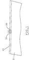
- a control device (1) is used to verify the correct sharpening of a band blade (2) formed by a laminar body provided with a sharp edge (20) delimited by two faces (21, 22) converging towards a plane in which the cutting edge lies.
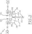
- the device shown in Figs.1-5 comprises two feeler probes (30, 31) arranged opposite to one another, in contact with the two sides of the cutting edge (20) so as to determine, as a function of the interaction of each probe (30, 31) with the blade (2), a signal (S1, S2) depending on the shape of the cutting edge (20).
- a signal S1, S2 depending on the shape of the cutting edge (20.
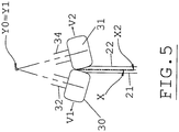
- said feeler probes (30, 31) are supported by respective arms (32, 34) that, in turn, are hinged about respective axes (Y0, Y1).
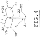
- the axes (Y0, Y1), that in Figs. 2 , 3 , 4 are perpendicular the plane of the sheet, are parallel to each other and are on opposite sides with respect to the plane (X) where the sides (20, 21) of the cutting edge (20) converge.
- each of the signals (S1, S2) produced by the movement of the feeler probes (30, 31) has a value corresponding to the displacement (V1, V2) of the same feeler probes (30, 31) relative to the blade (2).
- the present device comprises sensing means (R1, R2), i.e. detectors, for sensing the rotation of the arms (32, 34) about the respective axes (Y0, Y1) and electronic processing means apt to emit an error signal when there is the detection of discordant values between the amplitudes of the angles of rotation of the two feeler probes (30, 31).
- Each of said detectors (R1, R2) is a rotary encoder that measures the angle of rotation of the respective arm (32, 34) about the respective axis (Y0, Y1).
- Said signals (S1, S2) are electrical signals emitted by the transducers (R1, R2) and sent to the processing unit (E).
- Each of said transducers (R1, R2) can be applied on the rotation axis (Y0, Y1) of the respective feeler probe (31, 32).
- the error signal may be associated with an additional visual and/or acoustic signal.
- the two feeler probes (30, 31) are equidistant from the blade (2), as shown in Fig.2 .
- the signals (S1, S2) emitted by the detectors (R1, R2) are equal to each other for the two sides of the cutting edge (20) as they correspond to equal angular displacements of the feeler probes (30, 31) and at equal displacements angle of the arms (32, 34) around the axes (Y0, Y1).
- the two sides of the cutting edge (20) are oriented symmetrically with respect to said plane (X) and no error signal is produced.
- the signals (S1) and (S2) differ from each other and the device (1), by means of the unit (E), possibly taking into account a threshold value, emits an error signal used, for example, to command the intervention of means suitable to re-sharpen the blade (2) to bring it back to the optimal configuration (configuration in which the two sides of the cutting edge are oriented symmetrically with respect to the plane X).
- the error signal generated by the unit (E) can be used to control the emission of an alarm signal.
- Figs 3 and 4 along the vertical development of the blade (2) there are represented two additional axes (X1) and (X2) that indicate the incorrect configuration of the blade.
- the axis (X1) is to the left of the axis (X) and indicates a greater reduction of the left profile (face 21) of the cutting edge (20).
- the axis (X2) is to the right of the axis (X) to indicate a greater reduction of the right profile (face 21) of the cutting edge (20).
- the arms (32, 34) of the two feeler probes are hinged on a same axis, i.e. the axes (Y0) and (Y1) are coincident.
- a control device that can be used for checking the sharpening state of a blade having a cutting edge (20) delimited by two sides or faces (21, 22) converging towards a plane (X) containing the same cutting edge, comprises two control feeler probes (30, 31) each of which is in contact with a corresponding side (21, 22) of said cutting edge (20) and is connected with a respective transducer (R1, R2, R4), which produces an electrical displacement signal (S1, S2; S4) proportional to a displacement of the feeler probe with respect to said plane (X), and comprises a programmable electronic unit (E) that receives said displacement signals (S1, S2, S4) and compares them , emitting an error signal if the difference between the displacement signals exceeds a predetermined limit.
- the control device comprises a roller (4) with an external annular groove (40) in which passes the cutting edge (20) of the blade (2).
- the roller (4) is free to translate along an axis (A4) perpendicular to the plane (X) of the cutting edge (20).
- the roller (4) is also free to rotate about said axis (A4) .
- the roller (4) is associated with a lateral displacement detector (R4) constituted by a linear transducer which detects any displacement of the roller (4) to the right or to the left due to an asymmetric wear of the cutting edge (20).
- the signal (S4) is received by a programmable electronic unit (E) which emits an error signal (similarly to what is described above) if the absolute value of the signal, which can have positive or negative sign depending on whether the roller (4) moves towards the right or left, exceeds a predetermined limit.
- a device in accordance with the present invention comprises two control surfaces each of which is in contact with a corresponding side (21, 22) of said cutting edge (20) and is connected with at least one transducer (R1, R2; R4), which produces an electrical displacement signal (S1, S2, S4) proportional to a displacement of the control surface with respect to said plane (X), and comprises a programmable electronic processing unit (E) which receives the said displacement signals (S1, S2, S4) and processes them, emitting an error signal if the processing produces a value that exceeds a preset limit.
- control surfaces are the external surfaces of the feeler probes (30, 31) and the processing unit (E) produces an error signal if the difference between the values of the displacement signals (S1, S2) produced by the transducers (R1, R2) exceeds a given limit value.
- control surfaces are the surfaces that delimit the groove (40) of the roller (4) and the processing unit (E) emits an error signal if the absolute value of the displacement signal (S4) produced by the transducer (R4) is greater than a predetermined limit.
- the roller (4) can be made of steel, coated with wear-resistant ceramic material.
- Said error signal can be used to control the automatic intervention of restoring means adapted to restore the sharpening of the blade. More particularly, the intervention of said restoring means can be activated/deactivated automatically when the absolute value of the error signal is greater/less than a predetermined reference value.
- the restoration of the sharpening of the blade can be implemented by means of motorized grinding wheels (100) suitably arranged at the two sides of the blade, that is, by means of grinding wheels each of which is driven by a rotary actuator (101); by means of the actuators (101), the speed of rotation of the grinding wheels (100) is adjusted as long as the absolute value of the error signal is greater than the predetermined reference value.
- motorized grinding wheels (100) suitably arranged at the two sides of the blade, that is, by means of grinding wheels each of which is driven by a rotary actuator (101); by means of the actuators (101), the speed of rotation of the grinding wheels (100) is adjusted as long as the absolute value of the error signal is greater than the predetermined reference value.
- the restoration of the sharpening of the blade can be implemented by using the error signal for moving the motorized slides (102) adjusting the pressure exerted by the grinding wheels (100) on the two sides of the blade as long as the absolute value of the error signal is greater than the preset reference quantity as schematically indicated by the arrows "F" in Fig.7 .
- the actuators (5) and the slides (6) are represented in the diagram of Fig.7 , in which, for simplification, both the actuators (5) and the slides (6) are connected to the unit (4), although, in general, in a sharpening device it is preferred to connect both grinding wheels to rotary actuators or to motorized slides.
- the automatic restoration the blade sharpening can be selective in the sense that the left or the right grinding wheel (100) can be actuated depending on the sign, positive or negative, of the aforesaid error signal.
Landscapes
- Engineering & Computer Science (AREA)
- Mechanical Engineering (AREA)
- Life Sciences & Earth Sciences (AREA)
- Forests & Forestry (AREA)
- Wood Science & Technology (AREA)
- Physics & Mathematics (AREA)
- Acoustics & Sound (AREA)
- Finish Polishing, Edge Sharpening, And Grinding By Specific Grinding Devices (AREA)
- Constituent Portions Of Griding Lathes, Driving, Sensing And Control (AREA)
- Control Of Cutting Processes (AREA)
- Image Processing (AREA)
- Picture Signal Circuits (AREA)
- Facsimile Image Signal Circuits (AREA)
- Processing Of Stones Or Stones Resemblance Materials (AREA)
- Details Of Cutting Devices (AREA)
- Coating Apparatus (AREA)
- Nonmetal Cutting Devices (AREA)
Priority Applications (2)
| Application Number | Priority Date | Filing Date | Title |
|---|---|---|---|
| PL14828311T PL3074192T3 (pl) | 2013-11-30 | 2014-10-30 | Urządzenie do kontrolowania stanu naostrzenia ostrza |
| RS20171286A RS56650B1 (sr) | 2013-11-30 | 2014-10-30 | Uređaj za kontrolisanje stanja naoštrenosti sečiva |
Applications Claiming Priority (2)
| Application Number | Priority Date | Filing Date | Title |
|---|---|---|---|
| IT000292A ITFI20130292A1 (it) | 2013-11-30 | 2013-11-30 | Dispositivo per il controllo dell'affilatura di lame a nastro. |
| PCT/IT2014/000284 WO2015079466A1 (en) | 2013-11-30 | 2014-10-30 | Device for controlling the sharpening state of a blade |
Publications (2)
| Publication Number | Publication Date |
|---|---|
| EP3074192A1 EP3074192A1 (en) | 2016-10-05 |
| EP3074192B1 true EP3074192B1 (en) | 2017-11-15 |
Family
ID=49887054
Family Applications (3)
| Application Number | Title | Priority Date | Filing Date |
|---|---|---|---|
| EP14828311.2A Active EP3074192B1 (en) | 2013-11-30 | 2014-10-30 | Device for controlling the sharpening state of a blade |
| EP14828310.4A Active EP3074191B1 (en) | 2013-11-30 | 2014-10-30 | Control device for blades sharpening |
| EP14003693.0A Active EP2878413B1 (en) | 2013-11-30 | 2014-10-31 | Device for controlling the sharpening state of a blade |
Family Applications After (2)
| Application Number | Title | Priority Date | Filing Date |
|---|---|---|---|
| EP14828310.4A Active EP3074191B1 (en) | 2013-11-30 | 2014-10-30 | Control device for blades sharpening |
| EP14003693.0A Active EP2878413B1 (en) | 2013-11-30 | 2014-10-31 | Device for controlling the sharpening state of a blade |
Country Status (11)
| Country | Link |
|---|---|
| US (2) | US10029381B2 (pl) |
| EP (3) | EP3074192B1 (pl) |
| JP (2) | JP6353906B2 (pl) |
| CN (2) | CN105682873B (pl) |
| BR (2) | BR112016009345B1 (pl) |
| ES (3) | ES2653708T3 (pl) |
| IT (1) | ITFI20130292A1 (pl) |
| PL (2) | PL3074191T3 (pl) |
| RS (2) | RS56824B1 (pl) |
| RU (2) | RU2683677C1 (pl) |
| WO (2) | WO2015079465A1 (pl) |
Families Citing this family (9)
| Publication number | Priority date | Publication date | Assignee | Title |
|---|---|---|---|---|
| US11491602B2 (en) * | 2016-02-12 | 2022-11-08 | Darex, Llc | Powered sharpener with user directed indicator mechanism |
| CN109129047B (zh) * | 2017-03-13 | 2021-04-16 | 李冉 | 一种绞肉切片机万向磨刀器 |
| US10405305B2 (en) * | 2017-03-24 | 2019-09-03 | Qualcomm Incorporated | Single slot short PUCCH with support for intra slot frequency hopping |
| IT201700081306A1 (it) | 2017-07-18 | 2019-01-18 | Perini Fabio Spa | Gruppo di affilatura per una lama di taglio, macchina comprendente detto gruppo e metodo |
| CN108177033A (zh) * | 2018-02-08 | 2018-06-19 | 朱亿 | 刨槽机刨刀磨刀机 |
| CN113573846B (zh) * | 2018-10-16 | 2023-11-07 | 德瑞克斯有限公司 | 带有用户导向指示器机构的动力锐磨器 |
| CN112192354A (zh) * | 2019-07-07 | 2021-01-08 | 天津康利特变机电科技有限责任公司 | 一种纸板单根撑条成型机 |
| US11752591B2 (en) | 2020-03-17 | 2023-09-12 | Kimberly-Clark Worldwide, Inc. | Closed loop control system for blade sharpening |
| CN113021187B (zh) * | 2021-02-26 | 2022-05-03 | 浙江大学山东工业技术研究院 | 一种刀片自动化打磨机构 |
Family Cites Families (29)
| Publication number | Priority date | Publication date | Assignee | Title |
|---|---|---|---|---|
| DD101009A1 (pl) * | 1972-12-19 | 1973-10-12 | ||
| JPS5542742A (en) * | 1978-09-19 | 1980-03-26 | Mitsubishi Metal Corp | Blade edge grinding method |
| IT1156629B (it) * | 1982-07-14 | 1987-02-04 | Gd Spa | Dispositivo di affilatura per lame rotanti |
| JPS6399163A (ja) * | 1986-05-07 | 1988-04-30 | Taihei Mach Works Ltd | 刃先超仕上げ制御方法 |
| FR2652029B1 (fr) * | 1989-09-15 | 1995-01-27 | Lectra Systemes Sa | Methode et dispositif d'affutage automatique pour des lames coupe telles que celles utilisees dans les machines de coupe automatiques. |
| JPH0741603B2 (ja) * | 1992-06-09 | 1995-05-10 | 株式会社太平製作所 | 木工用長尺刃物及びその研削方法並びに装置 |
| JPH06246678A (ja) * | 1993-02-27 | 1994-09-06 | Iwashina Seisakusho:Kk | ロールペーパー切断装置 |
| JPH06294725A (ja) * | 1993-04-09 | 1994-10-21 | Inoac Corp | 切断刃の検査方法 |
| CN1078833C (zh) * | 1995-08-31 | 2002-02-06 | 格里森工场 | 用于校正刀盘体的方法和装置 |
| US6014919A (en) * | 1996-09-16 | 2000-01-18 | Precision Vascular Systems, Inc. | Method and apparatus for forming cuts in catheters, guidewires, and the like |
| US5793493A (en) * | 1997-04-04 | 1998-08-11 | Milliken Research Corporation | System for maintaining the cutting condition of double ground knife blades |
| DE19855773A1 (de) * | 1998-12-03 | 2000-06-15 | Walter Ag | Sägeblattschärfmaschine mit unabhängigen Zahnflankenschleifköpfen |
| DE10017719A1 (de) * | 2000-04-11 | 2001-10-18 | Knecht Maschb Gmbh | Vorrichtung zum Schleifen von Messern |
| DE10021614A1 (de) * | 2000-05-04 | 2001-11-08 | Hauni Maschinenbau Ag | Verfahren und Vorrichtung zum automatischen Nachschleifen von Tabakschneidemessern |
| FR2826894B1 (fr) * | 2001-07-04 | 2003-09-19 | Eastman Kodak Co | Procede de rectification et dispositif de controle d'un arbre de coupe |
| ITFI20020197A1 (it) * | 2002-10-18 | 2004-04-19 | Perini Fabio Spa | Una macchina troncatrice con un gruppo di affilatura per una lama, metodo di affilatura e lama per detta macchina |
| DE10258579B4 (de) * | 2002-12-16 | 2007-12-13 | Carl Mahr Holding Gmbh | Messeinrichtung |
| JP4481667B2 (ja) * | 2004-02-02 | 2010-06-16 | 株式会社ディスコ | 切削方法 |
| ITFI20040079A1 (it) * | 2004-04-01 | 2004-07-01 | Perini Fabio Spa | Macchina troncatrice con sistema di affilatura centrale |
| US7140119B2 (en) * | 2004-04-23 | 2006-11-28 | Corning Incorporated | Measurement of form of spherical and near-spherical optical surfaces |
| ITMI20041269A1 (it) * | 2004-06-24 | 2004-09-24 | Paper Converting Machine Co | Sistema di controllo della lama di taglio particolarmente per macchine troncatrici per il taglio di log di materiale in foglio |
| JP2007075923A (ja) * | 2005-09-12 | 2007-03-29 | Seiko Epson Corp | 裁断装置および記録裁断複合装置 |
| CN100501315C (zh) * | 2006-01-06 | 2009-06-17 | 鸿富锦精密工业(深圳)有限公司 | 一种表面轮廓检测方法 |
| RU2318644C1 (ru) * | 2006-04-24 | 2008-03-10 | Федеральное государственное образовательное учреждение высшего профессионального образования "Алтайский государственный аграрный университет" | Способ заострения режущих кромок |
| DE102006019354B3 (de) * | 2006-04-24 | 2007-07-19 | Rattunde & Co Gmbh | Profilmessung von Rohrenden |
| DE102010019852A1 (de) * | 2010-05-07 | 2011-11-10 | Knecht Maschinenbau Gmbh | Vorrichtung zum Schleifen von Handmessern |
| US9079284B2 (en) * | 2010-12-15 | 2015-07-14 | Marc Christenson | Automated instrument sharpening and cleaning system |
| EP3175952B1 (de) * | 2011-06-06 | 2024-07-31 | Weber Food Technology GmbH | Vorrichtung und verfahren zum schleifen von rotationsmessern |
| US8915766B1 (en) * | 2014-05-22 | 2014-12-23 | Dmitriy Kolchin | Automatic knife sharpener and a method for its use |
-
2013
- 2013-11-30 IT IT000292A patent/ITFI20130292A1/it unknown
-
2014
- 2014-10-30 JP JP2016534185A patent/JP6353906B2/ja not_active Expired - Fee Related
- 2014-10-30 US US15/038,887 patent/US10029381B2/en active Active
- 2014-10-30 WO PCT/IT2014/000283 patent/WO2015079465A1/en not_active Ceased
- 2014-10-30 CN CN201480058230.1A patent/CN105682873B/zh not_active Expired - Fee Related
- 2014-10-30 ES ES14828311.2T patent/ES2653708T3/es active Active
- 2014-10-30 ES ES14828310.4T patent/ES2660021T3/es active Active
- 2014-10-30 RS RS20180125A patent/RS56824B1/sr unknown
- 2014-10-30 US US15/038,866 patent/US10029380B2/en active Active
- 2014-10-30 BR BR112016009345-3A patent/BR112016009345B1/pt not_active IP Right Cessation
- 2014-10-30 JP JP2016534184A patent/JP6297693B2/ja not_active Expired - Fee Related
- 2014-10-30 RU RU2016125867A patent/RU2683677C1/ru active
- 2014-10-30 CN CN201480058229.9A patent/CN105682872B/zh not_active Expired - Fee Related
- 2014-10-30 EP EP14828311.2A patent/EP3074192B1/en active Active
- 2014-10-30 RU RU2016125859A patent/RU2673897C1/ru active
- 2014-10-30 RS RS20171286A patent/RS56650B1/sr unknown
- 2014-10-30 EP EP14828310.4A patent/EP3074191B1/en active Active
- 2014-10-30 WO PCT/IT2014/000284 patent/WO2015079466A1/en not_active Ceased
- 2014-10-30 PL PL14828310T patent/PL3074191T3/pl unknown
- 2014-10-30 BR BR112016009354-2A patent/BR112016009354B1/pt not_active IP Right Cessation
- 2014-10-30 PL PL14828311T patent/PL3074192T3/pl unknown
- 2014-10-31 EP EP14003693.0A patent/EP2878413B1/en active Active
- 2014-10-31 ES ES14003693.0T patent/ES2578379T3/es active Active
Non-Patent Citations (1)
| Title |
|---|
| None * |
Also Published As
| Publication number | Publication date |
|---|---|
| EP3074191B1 (en) | 2018-01-17 |
| WO2015079465A1 (en) | 2015-06-04 |
| EP3074191A1 (en) | 2016-10-05 |
| JP6297693B2 (ja) | 2018-03-20 |
| ES2653708T3 (es) | 2018-02-08 |
| CN105682872A (zh) | 2016-06-15 |
| US10029380B2 (en) | 2018-07-24 |
| RU2683677C1 (ru) | 2019-04-01 |
| CN105682872B (zh) | 2017-09-29 |
| JP2016538145A (ja) | 2016-12-08 |
| JP6353906B2 (ja) | 2018-07-04 |
| ES2578379T3 (es) | 2016-07-26 |
| US20170021520A1 (en) | 2017-01-26 |
| JP2016539014A (ja) | 2016-12-15 |
| EP2878413B1 (en) | 2016-05-18 |
| RS56824B1 (sr) | 2018-04-30 |
| US20170021521A1 (en) | 2017-01-26 |
| RS56650B1 (sr) | 2018-03-30 |
| ES2660021T3 (es) | 2018-03-20 |
| RU2673897C1 (ru) | 2018-12-03 |
| ITFI20130292A1 (it) | 2015-05-31 |
| WO2015079466A1 (en) | 2015-06-04 |
| PL3074191T3 (pl) | 2018-05-30 |
| CN105682873A (zh) | 2016-06-15 |
| US10029381B2 (en) | 2018-07-24 |
| CN105682873B (zh) | 2017-08-18 |
| BR112016009354B1 (pt) | 2021-08-10 |
| BR112016009345B1 (pt) | 2020-12-15 |
| EP2878413A1 (en) | 2015-06-03 |
| BR112016009354A2 (pt) | 2017-08-01 |
| PL3074192T3 (pl) | 2018-03-30 |
| EP3074192A1 (en) | 2016-10-05 |
Similar Documents
| Publication | Publication Date | Title |
|---|---|---|
| EP3074192B1 (en) | Device for controlling the sharpening state of a blade | |
| EP3077157B1 (en) | Device for sharpening blades | |
| CN110177666B (zh) | 用于检查预切割装置的正确操作的方法和复卷机 | |
| CN105682855B (zh) | 用于磨锐刀片的设备 | |
| EP2957184A1 (en) | Adjustment apparatus | |
| ITRM20130262A1 (it) | Macchina per la lavorazione di pannelli. | |
| JP2022536897A (ja) | 研削装置付き紙ロール用切断機 | |
| JP2718994B2 (ja) | コード入りコーティングシートの耳ゴム検査装置 | |
| US20220176579A1 (en) | Cutting machine for paper material logs with a sharpening unit |
Legal Events
| Date | Code | Title | Description |
|---|---|---|---|
| PUAI | Public reference made under article 153(3) epc to a published international application that has entered the european phase |
Free format text: ORIGINAL CODE: 0009012 |
|
| 17P | Request for examination filed |
Effective date: 20160413 |
|
| AK | Designated contracting states |
Kind code of ref document: A1 Designated state(s): AL AT BE BG CH CY CZ DE DK EE ES FI FR GB GR HR HU IE IS IT LI LT LU LV MC MK MT NL NO PL PT RO RS SE SI SK SM TR |
|
| AX | Request for extension of the european patent |
Extension state: BA ME |
|
| DAX | Request for extension of the european patent (deleted) | ||
| GRAP | Despatch of communication of intention to grant a patent |
Free format text: ORIGINAL CODE: EPIDOSNIGR1 |
|
| INTG | Intention to grant announced |
Effective date: 20170814 |
|
| GRAS | Grant fee paid |
Free format text: ORIGINAL CODE: EPIDOSNIGR3 |
|
| GRAA | (expected) grant |
Free format text: ORIGINAL CODE: 0009210 |
|
| AK | Designated contracting states |
Kind code of ref document: B1 Designated state(s): AL AT BE BG CH CY CZ DE DK EE ES FI FR GB GR HR HU IE IS IT LI LT LU LV MC MK MT NL NO PL PT RO RS SE SI SK SM TR |
|
| REG | Reference to a national code |
Ref country code: CH Ref legal event code: EP Ref country code: GB Ref legal event code: FG4D Ref country code: AT Ref legal event code: REF Ref document number: 945817 Country of ref document: AT Kind code of ref document: T Effective date: 20171115 |
|
| REG | Reference to a national code |
Ref country code: IE Ref legal event code: FG4D |
|
| REG | Reference to a national code |
Ref country code: RO Ref legal event code: EPE |
|
| REG | Reference to a national code |
Ref country code: DE Ref legal event code: R096 Ref document number: 602014017400 Country of ref document: DE |
|
| REG | Reference to a national code |
Ref country code: SE Ref legal event code: TRGR |
|
| REG | Reference to a national code |
Ref country code: ES Ref legal event code: FG2A Ref document number: 2653708 Country of ref document: ES Kind code of ref document: T3 Effective date: 20180208 |
|
| REG | Reference to a national code |
Ref country code: NL Ref legal event code: MP Effective date: 20171115 |
|
| REG | Reference to a national code |
Ref country code: LT Ref legal event code: MG4D |
|
| REG | Reference to a national code |
Ref country code: AT Ref legal event code: MK05 Ref document number: 945817 Country of ref document: AT Kind code of ref document: T Effective date: 20171115 |
|
| PG25 | Lapsed in a contracting state [announced via postgrant information from national office to epo] |
Ref country code: NO Free format text: LAPSE BECAUSE OF FAILURE TO SUBMIT A TRANSLATION OF THE DESCRIPTION OR TO PAY THE FEE WITHIN THE PRESCRIBED TIME-LIMIT Effective date: 20180215 Ref country code: NL Free format text: LAPSE BECAUSE OF FAILURE TO SUBMIT A TRANSLATION OF THE DESCRIPTION OR TO PAY THE FEE WITHIN THE PRESCRIBED TIME-LIMIT Effective date: 20171115 Ref country code: LT Free format text: LAPSE BECAUSE OF FAILURE TO SUBMIT A TRANSLATION OF THE DESCRIPTION OR TO PAY THE FEE WITHIN THE PRESCRIBED TIME-LIMIT Effective date: 20171115 |
|
| PG25 | Lapsed in a contracting state [announced via postgrant information from national office to epo] |
Ref country code: AT Free format text: LAPSE BECAUSE OF FAILURE TO SUBMIT A TRANSLATION OF THE DESCRIPTION OR TO PAY THE FEE WITHIN THE PRESCRIBED TIME-LIMIT Effective date: 20171115 Ref country code: BG Free format text: LAPSE BECAUSE OF FAILURE TO SUBMIT A TRANSLATION OF THE DESCRIPTION OR TO PAY THE FEE WITHIN THE PRESCRIBED TIME-LIMIT Effective date: 20180215 Ref country code: LV Free format text: LAPSE BECAUSE OF FAILURE TO SUBMIT A TRANSLATION OF THE DESCRIPTION OR TO PAY THE FEE WITHIN THE PRESCRIBED TIME-LIMIT Effective date: 20171115 Ref country code: GR Free format text: LAPSE BECAUSE OF FAILURE TO SUBMIT A TRANSLATION OF THE DESCRIPTION OR TO PAY THE FEE WITHIN THE PRESCRIBED TIME-LIMIT Effective date: 20180216 Ref country code: HR Free format text: LAPSE BECAUSE OF FAILURE TO SUBMIT A TRANSLATION OF THE DESCRIPTION OR TO PAY THE FEE WITHIN THE PRESCRIBED TIME-LIMIT Effective date: 20171115 |
|
| PG25 | Lapsed in a contracting state [announced via postgrant information from national office to epo] |
Ref country code: CZ Free format text: LAPSE BECAUSE OF FAILURE TO SUBMIT A TRANSLATION OF THE DESCRIPTION OR TO PAY THE FEE WITHIN THE PRESCRIBED TIME-LIMIT Effective date: 20171115 Ref country code: CY Free format text: LAPSE BECAUSE OF FAILURE TO SUBMIT A TRANSLATION OF THE DESCRIPTION OR TO PAY THE FEE WITHIN THE PRESCRIBED TIME-LIMIT Effective date: 20171115 Ref country code: EE Free format text: LAPSE BECAUSE OF FAILURE TO SUBMIT A TRANSLATION OF THE DESCRIPTION OR TO PAY THE FEE WITHIN THE PRESCRIBED TIME-LIMIT Effective date: 20171115 Ref country code: DK Free format text: LAPSE BECAUSE OF FAILURE TO SUBMIT A TRANSLATION OF THE DESCRIPTION OR TO PAY THE FEE WITHIN THE PRESCRIBED TIME-LIMIT Effective date: 20171115 Ref country code: SK Free format text: LAPSE BECAUSE OF FAILURE TO SUBMIT A TRANSLATION OF THE DESCRIPTION OR TO PAY THE FEE WITHIN THE PRESCRIBED TIME-LIMIT Effective date: 20171115 |
|
| REG | Reference to a national code |
Ref country code: DE Ref legal event code: R097 Ref document number: 602014017400 Country of ref document: DE |
|
| PG25 | Lapsed in a contracting state [announced via postgrant information from national office to epo] |
Ref country code: SM Free format text: LAPSE BECAUSE OF FAILURE TO SUBMIT A TRANSLATION OF THE DESCRIPTION OR TO PAY THE FEE WITHIN THE PRESCRIBED TIME-LIMIT Effective date: 20171115 |
|
| PLBE | No opposition filed within time limit |
Free format text: ORIGINAL CODE: 0009261 |
|
| STAA | Information on the status of an ep patent application or granted ep patent |
Free format text: STATUS: NO OPPOSITION FILED WITHIN TIME LIMIT |
|
| REG | Reference to a national code |
Ref country code: FR Ref legal event code: PLFP Year of fee payment: 5 |
|
| 26N | No opposition filed |
Effective date: 20180817 |
|
| PG25 | Lapsed in a contracting state [announced via postgrant information from national office to epo] |
Ref country code: SI Free format text: LAPSE BECAUSE OF FAILURE TO SUBMIT A TRANSLATION OF THE DESCRIPTION OR TO PAY THE FEE WITHIN THE PRESCRIBED TIME-LIMIT Effective date: 20171115 |
|
| REG | Reference to a national code |
Ref country code: CH Ref legal event code: PL |
|
| REG | Reference to a national code |
Ref country code: BE Ref legal event code: MM Effective date: 20181031 |
|
| PG25 | Lapsed in a contracting state [announced via postgrant information from national office to epo] |
Ref country code: MC Free format text: LAPSE BECAUSE OF FAILURE TO SUBMIT A TRANSLATION OF THE DESCRIPTION OR TO PAY THE FEE WITHIN THE PRESCRIBED TIME-LIMIT Effective date: 20171115 Ref country code: LU Free format text: LAPSE BECAUSE OF NON-PAYMENT OF DUE FEES Effective date: 20181030 |
|
| REG | Reference to a national code |
Ref country code: IE Ref legal event code: MM4A |
|
| PG25 | Lapsed in a contracting state [announced via postgrant information from national office to epo] |
Ref country code: BE Free format text: LAPSE BECAUSE OF NON-PAYMENT OF DUE FEES Effective date: 20181031 Ref country code: LI Free format text: LAPSE BECAUSE OF NON-PAYMENT OF DUE FEES Effective date: 20181031 Ref country code: CH Free format text: LAPSE BECAUSE OF NON-PAYMENT OF DUE FEES Effective date: 20181031 |
|
| PG25 | Lapsed in a contracting state [announced via postgrant information from national office to epo] |
Ref country code: IE Free format text: LAPSE BECAUSE OF NON-PAYMENT OF DUE FEES Effective date: 20181030 |
|
| PG25 | Lapsed in a contracting state [announced via postgrant information from national office to epo] |
Ref country code: MT Free format text: LAPSE BECAUSE OF NON-PAYMENT OF DUE FEES Effective date: 20181030 |
|
| PG25 | Lapsed in a contracting state [announced via postgrant information from national office to epo] |
Ref country code: PT Free format text: LAPSE BECAUSE OF FAILURE TO SUBMIT A TRANSLATION OF THE DESCRIPTION OR TO PAY THE FEE WITHIN THE PRESCRIBED TIME-LIMIT Effective date: 20171115 |
|
| PG25 | Lapsed in a contracting state [announced via postgrant information from national office to epo] |
Ref country code: MK Free format text: LAPSE BECAUSE OF NON-PAYMENT OF DUE FEES Effective date: 20171115 Ref country code: HU Free format text: LAPSE BECAUSE OF FAILURE TO SUBMIT A TRANSLATION OF THE DESCRIPTION OR TO PAY THE FEE WITHIN THE PRESCRIBED TIME-LIMIT; INVALID AB INITIO Effective date: 20141030 |
|
| PG25 | Lapsed in a contracting state [announced via postgrant information from national office to epo] |
Ref country code: AL Free format text: LAPSE BECAUSE OF FAILURE TO SUBMIT A TRANSLATION OF THE DESCRIPTION OR TO PAY THE FEE WITHIN THE PRESCRIBED TIME-LIMIT Effective date: 20171115 Ref country code: IS Free format text: LAPSE BECAUSE OF FAILURE TO SUBMIT A TRANSLATION OF THE DESCRIPTION OR TO PAY THE FEE WITHIN THE PRESCRIBED TIME-LIMIT Effective date: 20180315 |
|
| PGFP | Annual fee paid to national office [announced via postgrant information from national office to epo] |
Ref country code: GB Payment date: 20211022 Year of fee payment: 8 Ref country code: DE Payment date: 20211020 Year of fee payment: 8 Ref country code: ES Payment date: 20211224 Year of fee payment: 8 Ref country code: FI Payment date: 20211021 Year of fee payment: 8 Ref country code: RO Payment date: 20211021 Year of fee payment: 8 Ref country code: RS Payment date: 20211025 Year of fee payment: 8 Ref country code: SE Payment date: 20211020 Year of fee payment: 8 Ref country code: TR Payment date: 20211027 Year of fee payment: 8 |
|
| PGFP | Annual fee paid to national office [announced via postgrant information from national office to epo] |
Ref country code: FR Payment date: 20211022 Year of fee payment: 8 |
|
| PGFP | Annual fee paid to national office [announced via postgrant information from national office to epo] |
Ref country code: PL Payment date: 20211026 Year of fee payment: 8 |
|
| REG | Reference to a national code |
Ref country code: DE Ref legal event code: R119 Ref document number: 602014017400 Country of ref document: DE |
|
| REG | Reference to a national code |
Ref country code: SE Ref legal event code: EUG |
|
| GBPC | Gb: european patent ceased through non-payment of renewal fee |
Effective date: 20221030 |
|
| PG25 | Lapsed in a contracting state [announced via postgrant information from national office to epo] |
Ref country code: RS Free format text: LAPSE BECAUSE OF NON-PAYMENT OF DUE FEES Effective date: 20221030 Ref country code: RO Free format text: LAPSE BECAUSE OF NON-PAYMENT OF DUE FEES Effective date: 20221030 Ref country code: FR Free format text: LAPSE BECAUSE OF NON-PAYMENT OF DUE FEES Effective date: 20221031 Ref country code: DE Free format text: LAPSE BECAUSE OF NON-PAYMENT OF DUE FEES Effective date: 20230503 |
|
| PG25 | Lapsed in a contracting state [announced via postgrant information from national office to epo] |
Ref country code: SE Free format text: LAPSE BECAUSE OF NON-PAYMENT OF DUE FEES Effective date: 20221031 |
|
| PG25 | Lapsed in a contracting state [announced via postgrant information from national office to epo] |
Ref country code: GB Free format text: LAPSE BECAUSE OF NON-PAYMENT OF DUE FEES Effective date: 20221030 |
|
| PG25 | Lapsed in a contracting state [announced via postgrant information from national office to epo] |
Ref country code: PL Free format text: LAPSE BECAUSE OF NON-PAYMENT OF DUE FEES Effective date: 20221030 |
|
| REG | Reference to a national code |
Ref country code: ES Ref legal event code: FD2A Effective date: 20231204 |
|
| PG25 | Lapsed in a contracting state [announced via postgrant information from national office to epo] |
Ref country code: ES Free format text: LAPSE BECAUSE OF NON-PAYMENT OF DUE FEES Effective date: 20221031 |
|
| PG25 | Lapsed in a contracting state [announced via postgrant information from national office to epo] |
Ref country code: ES Free format text: LAPSE BECAUSE OF NON-PAYMENT OF DUE FEES Effective date: 20221031 |
|
| PG25 | Lapsed in a contracting state [announced via postgrant information from national office to epo] |
Ref country code: FI Free format text: LAPSE BECAUSE OF NON-PAYMENT OF DUE FEES Effective date: 20221030 |
|
| PGFP | Annual fee paid to national office [announced via postgrant information from national office to epo] |
Ref country code: IT Payment date: 20250918 Year of fee payment: 12 |