EP3073937B1 - Medizinisches instrumentarium - Google Patents
Medizinisches instrumentarium Download PDFInfo
- Publication number
- EP3073937B1 EP3073937B1 EP14796497.7A EP14796497A EP3073937B1 EP 3073937 B1 EP3073937 B1 EP 3073937B1 EP 14796497 A EP14796497 A EP 14796497A EP 3073937 B1 EP3073937 B1 EP 3073937B1
- Authority
- EP
- European Patent Office
- Prior art keywords
- shaped body
- accordance
- coupling
- medical instrumentation
- abutment surface
- Prior art date
- Legal status (The legal status is an assumption and is not a legal conclusion. Google has not performed a legal analysis and makes no representation as to the accuracy of the status listed.)
- Active
Links
Images


Classifications
-
- A—HUMAN NECESSITIES
- A61—MEDICAL OR VETERINARY SCIENCE; HYGIENE
- A61F—FILTERS IMPLANTABLE INTO BLOOD VESSELS; PROSTHESES; DEVICES PROVIDING PATENCY TO, OR PREVENTING COLLAPSING OF, TUBULAR STRUCTURES OF THE BODY, e.g. STENTS; ORTHOPAEDIC, NURSING OR CONTRACEPTIVE DEVICES; FOMENTATION; TREATMENT OR PROTECTION OF EYES OR EARS; BANDAGES, DRESSINGS OR ABSORBENT PADS; FIRST-AID KITS
- A61F2/00—Filters implantable into blood vessels; Prostheses, i.e. artificial substitutes or replacements for parts of the body; Appliances for connecting them with the body; Devices providing patency to, or preventing collapsing of, tubular structures of the body, e.g. stents
- A61F2/02—Prostheses implantable into the body
- A61F2/30—Joints
- A61F2/46—Special tools for implanting artificial joints
- A61F2/4603—Special tools for implanting artificial joints for insertion or extraction of endoprosthetic joints or of accessories thereof
- A61F2/4609—Special tools for implanting artificial joints for insertion or extraction of endoprosthetic joints or of accessories thereof of acetabular cups
-
- A—HUMAN NECESSITIES
- A61—MEDICAL OR VETERINARY SCIENCE; HYGIENE
- A61B—DIAGNOSIS; SURGERY; IDENTIFICATION
- A61B17/00—Surgical instruments, devices or methods
- A61B17/16—Instruments for performing osteoclasis; Drills or chisels for bones; Trepans
- A61B17/17—Guides or aligning means for drills, mills, pins or wires
- A61B17/1739—Guides or aligning means for drills, mills, pins or wires specially adapted for particular parts of the body
- A61B17/1742—Guides or aligning means for drills, mills, pins or wires specially adapted for particular parts of the body for the hip
- A61B17/1746—Guides or aligning means for drills, mills, pins or wires specially adapted for particular parts of the body for the hip for the acetabulum
-
- A—HUMAN NECESSITIES
- A61—MEDICAL OR VETERINARY SCIENCE; HYGIENE
- A61B—DIAGNOSIS; SURGERY; IDENTIFICATION
- A61B34/00—Computer-aided surgery; Manipulators or robots specially adapted for use in surgery
- A61B34/10—Computer-aided planning, simulation or modelling of surgical operations
-
- A—HUMAN NECESSITIES
- A61—MEDICAL OR VETERINARY SCIENCE; HYGIENE
- A61F—FILTERS IMPLANTABLE INTO BLOOD VESSELS; PROSTHESES; DEVICES PROVIDING PATENCY TO, OR PREVENTING COLLAPSING OF, TUBULAR STRUCTURES OF THE BODY, e.g. STENTS; ORTHOPAEDIC, NURSING OR CONTRACEPTIVE DEVICES; FOMENTATION; TREATMENT OR PROTECTION OF EYES OR EARS; BANDAGES, DRESSINGS OR ABSORBENT PADS; FIRST-AID KITS
- A61F2/00—Filters implantable into blood vessels; Prostheses, i.e. artificial substitutes or replacements for parts of the body; Appliances for connecting them with the body; Devices providing patency to, or preventing collapsing of, tubular structures of the body, e.g. stents
- A61F2/02—Prostheses implantable into the body
- A61F2/30—Joints
- A61F2/46—Special tools for implanting artificial joints
- A61F2/4657—Measuring instruments used for implanting artificial joints
-
- A—HUMAN NECESSITIES
- A61—MEDICAL OR VETERINARY SCIENCE; HYGIENE
- A61B—DIAGNOSIS; SURGERY; IDENTIFICATION
- A61B17/00—Surgical instruments, devices or methods
- A61B17/56—Surgical instruments or methods for treatment of bones or joints; Devices specially adapted therefor
- A61B2017/568—Surgical instruments or methods for treatment of bones or joints; Devices specially adapted therefor produced with shape and dimensions specific for an individual patient
-
- A—HUMAN NECESSITIES
- A61—MEDICAL OR VETERINARY SCIENCE; HYGIENE
- A61B—DIAGNOSIS; SURGERY; IDENTIFICATION
- A61B34/00—Computer-aided surgery; Manipulators or robots specially adapted for use in surgery
- A61B34/10—Computer-aided planning, simulation or modelling of surgical operations
- A61B2034/108—Computer aided selection or customisation of medical implants or cutting guides
-
- A—HUMAN NECESSITIES
- A61—MEDICAL OR VETERINARY SCIENCE; HYGIENE
- A61F—FILTERS IMPLANTABLE INTO BLOOD VESSELS; PROSTHESES; DEVICES PROVIDING PATENCY TO, OR PREVENTING COLLAPSING OF, TUBULAR STRUCTURES OF THE BODY, e.g. STENTS; ORTHOPAEDIC, NURSING OR CONTRACEPTIVE DEVICES; FOMENTATION; TREATMENT OR PROTECTION OF EYES OR EARS; BANDAGES, DRESSINGS OR ABSORBENT PADS; FIRST-AID KITS
- A61F2/00—Filters implantable into blood vessels; Prostheses, i.e. artificial substitutes or replacements for parts of the body; Appliances for connecting them with the body; Devices providing patency to, or preventing collapsing of, tubular structures of the body, e.g. stents
- A61F2/02—Prostheses implantable into the body
- A61F2/30—Joints
- A61F2/3094—Designing or manufacturing processes
- A61F2/30942—Designing or manufacturing processes for designing or making customized prostheses, e.g. using templates, CT or NMR scans, finite-element analysis or CAD-CAM techniques
-
- A—HUMAN NECESSITIES
- A61—MEDICAL OR VETERINARY SCIENCE; HYGIENE
- A61F—FILTERS IMPLANTABLE INTO BLOOD VESSELS; PROSTHESES; DEVICES PROVIDING PATENCY TO, OR PREVENTING COLLAPSING OF, TUBULAR STRUCTURES OF THE BODY, e.g. STENTS; ORTHOPAEDIC, NURSING OR CONTRACEPTIVE DEVICES; FOMENTATION; TREATMENT OR PROTECTION OF EYES OR EARS; BANDAGES, DRESSINGS OR ABSORBENT PADS; FIRST-AID KITS
- A61F2/00—Filters implantable into blood vessels; Prostheses, i.e. artificial substitutes or replacements for parts of the body; Appliances for connecting them with the body; Devices providing patency to, or preventing collapsing of, tubular structures of the body, e.g. stents
- A61F2/02—Prostheses implantable into the body
- A61F2/30—Joints
- A61F2/46—Special tools for implanting artificial joints
- A61F2/4657—Measuring instruments used for implanting artificial joints
- A61F2002/4668—Measuring instruments used for implanting artificial joints for measuring angles
-
- A—HUMAN NECESSITIES
- A61—MEDICAL OR VETERINARY SCIENCE; HYGIENE
- A61F—FILTERS IMPLANTABLE INTO BLOOD VESSELS; PROSTHESES; DEVICES PROVIDING PATENCY TO, OR PREVENTING COLLAPSING OF, TUBULAR STRUCTURES OF THE BODY, e.g. STENTS; ORTHOPAEDIC, NURSING OR CONTRACEPTIVE DEVICES; FOMENTATION; TREATMENT OR PROTECTION OF EYES OR EARS; BANDAGES, DRESSINGS OR ABSORBENT PADS; FIRST-AID KITS
- A61F2/00—Filters implantable into blood vessels; Prostheses, i.e. artificial substitutes or replacements for parts of the body; Appliances for connecting them with the body; Devices providing patency to, or preventing collapsing of, tubular structures of the body, e.g. stents
- A61F2/02—Prostheses implantable into the body
- A61F2/30—Joints
- A61F2/46—Special tools for implanting artificial joints
- A61F2002/4687—Mechanical guides for implantation instruments
Definitions
- the present invention relates to a medical instrumentation, in particular for implanting an acetabulum, comprising a medical alignment with a molded body, which has a patient-individual, facing away from the molding body and deviating from a spherical surface cut bone abutment surface which is formed corresponding to a bone surface of the patient, said Shaped body having at least one view edge with a height of view, wherein the view edge adjacent to the patient-individual bone abutment surface and wherein a transition between the viewing edge and the patient-individual bone abutment surface is tangentenunstetig.
- the optimal positioning of the acetabulum of the hip joint endoprosthesis to be implanted is of importance.
- landmarks are susceptible to error because the bone under the tissue is not always clearly palpable.
- Another problem with locating landmarks is that they must be easily accessible. This is not the case especially in the case of a surgical intervention in a lateral position.
- the molding is cup-shaped and has a constant or substantially constant thickness and that the bone abutment surface has a contour which at least part of the fossa and / or a part of Incisura acetabuli corresponds.
- the solution proposed according to the invention avoids that the alignment instrument with the bone abutment surface is not completely applied to the bone surface, for example a region of the acetabulum of the patient.
- the bone abutment area is so large that the entire acetabulum is used as a reference, the doctor no longer has a view into the acetabulum and thus no longer orientation. He then has to rely solely on his manual feeling, whether the molding is sitting correctly, so flat, in the acetabulum. This is particularly difficult to feel for a relatively large contact surface.
- the physician can not only feel but also see the optimal abutment of the shaped body on the acetabulum.
- the abutment of the viewing edge with the patient-specific bone abutment surface makes it possible for the surgeon to clearly identify and especially with palpation instruments, for example a probe hook, to check whether the shaped body is seated in the predetermined manner in the acetabulum with the patient-specific bone abutment surface. If this is the case, then the alignment instrument can be used in particular to unambiguously determine the position of the pelvis of the patient by setting reference pins or by referencing by means of a navigation system.
- the shaped body can in particular have two, three, four or even more viewing edges. These may be at least partially parallel or at a defined angle relative to each other. Also possible in particular are self-contained, annular view edges, for example in the form of inner boundary surfaces of apertures in the molding. It is favorable that the shaped body is cup-shaped and has a constant or substantially constant thickness. This makes it particularly easy to manufacture, for example by casting or 3D printing.
- the bone abutment surface has a contour which corresponds to at least a part of the fossa and / or a part of the incisura acetabuli.
- the two structures mentioned, ie the fossa and the acetabular incisura allow an optimal patient-specific reference for the alignment of the acetabulum to be implanted on the pelvic bone of the patient.
- alignment pins or fastening pins can then be optionally positioned and fixed on the pelvic bone or else the position of the alignment instrument, in particular of the molding, with the aid of a navigation system, for example using a navigated palpation instrument reference.
- a particularly reliable verification of the exact position of the shaped body in the acetabulum is possible in particular in that the at least one viewing edge has a width or height which corresponds to at least a minimum thickness of the shaped body.
- the at least one viewing edge has a width or height which corresponds at most to three times the minimum thickness of the molded body.
- the at least one viewing edge forms a flat or substantially planar surface area or forms a boundary surface of a recess of the shaped body, which recess at least partially penetrates the bone abutment surface.
- the bone abutment surface can point away from the molding body in the distal direction. The recess can then be formed in particular laterally on the molded body and extend to the patient-specific bone abutment surface.
- the shaped body can also have an edge and optionally also a surface area which is not shaped individually for each patient.
- this area may define a section of a surface of an ellipsoid, in particular a sphere.
- This surface region can be formed, for example, on a carrier, which forms a part of the shaped body, on which the patient-specific bone abutment surface is formed on a projection pointing in the distal direction.
- the at least one recess is designed in the form of an opening and if the at least one viewing edge forms an inner surface of the opening.
- one, two, three, four or more apertures may be provided on the shaped body, which allow the surgeon to see the acetabulum through the shaped body and, in particular, visually inspect the obturator by virtue of the direct view of the apertures bounding the apertures Form body in the desired manner is applied to the acetabulum or not.
- the alignment instrument defines an instrument longitudinal axis and if a longitudinal axis of the aperture extends parallel or substantially parallel to the instrument longitudinal axis. This allows the surgeon optimum optical access to the acetabulum through the molded body.
- the opening can be produced if it is designed in the form of a bore.
- the alignment instrument has two, three, four or more recesses.
- any combinations of planar or substantially planar alignment edges with recesses, in particular in the form of apertures, are conceivable.
- the bone abutment surface is at least partially adapted to a contour of the acetabulum of the patient.
- the alignment can be clearly positioned on the acetabulum, since this normally has a shape deviating from a rotational symmetry, which allows the application of a matched to the bone contour patient-specific bone abutment surface only in exactly one defined position.
- At least one fastener element receptacle is arranged or formed on the molded body.
- two, three or more fastening element receptacles can be provided. These are formed in particular corresponding to fastening pins, which can optionally serve to fix the shaped body on the pelvic bone, or else to establish a referencing device with corresponding marker elements for referencing the pelvis with the aid of a surgical navigation system.
- the bone abutment surface and / or the shaped body are produced by casting or 3D printing.
- the shaped body can be produced in a simple and cost-effective manner, in particular from a plastic, preferably a sterilizable plastic.
- the shaped body or the bone abutment surface can also be produced from a metal.
- the bone abutment surface of the shaped body defines bone abutment surface contour data which non-invasively correspond or substantially correspond to certain bone contour data of the patient.
- the patient's bone contour data may be data from X-ray or magnetic resonance images. These can be determined in particular already in digital form by corresponding X-ray and magnetic resonance apparatuses and then further processed directly to print data or for a CAD-controlled milling machine, for preparing a casting mold or for direct printing of the bone contact surface or of the molded body with a 3D printer.
- the alignment instrument can be handled particularly easily if it comprises a grip element.
- the grip element is releasably connectable with the molded body is formed.
- the molding can be positioned, for example, with the grip element on the pelvic bone and temporarily fixed there with fasteners, such as bone pins or bone screws.
- the handle element can then optionally be released from the molding.
- the handle element and the molded body can be connected to one another and also detached from one another when the alignment instrument has a coupling device for temporary coupling of the molded body to the handle element.
- the gripping element and the molded body can be connected to each other, if the coupling device comprises at least a first coupling element and at least a second coupling element, when the at least one first and second coupling elements are formed corresponding to each other and engage in a coupling position and disengage in a release position.
- connection of the gripping element to the molded body becomes particularly simple, in particular even if there is no direct view of the surgical site, if the at least one first coupling element is in the form of a coupling receptacle and if the at least one second coupling element is in the form of a coupling protrusion.
- the coupling receptacle can optionally be formed on the handle element or on the molded body.
- the at least one first coupling element comprises a female threaded portion and if the at least one second coupling element comprise a corresponding male threaded portion.
- This embodiment makes it possible in particular to screw the handle element to the molding or unscrew it.
- one of the two coupling elements is arranged or formed on the molded body and the other of the two coupling elements on the grip element.
- the at least one first coupling element can be arranged or formed on the shaped body and the at least one second coupling element on the grip element.
- the handling of the alignment instrument can be further improved if the grip element comprises an elongated shaft and if a grip region is arranged or formed on a proximal end region of the shaft.
- the grip element can be ergonomically designed.
- the shaft defines a longitudinal axis and if a proximal end face of the shaft is designed in the form of a striking surface for a striking tool.
- the handle element in particular for driving, for example, the shaped body into the acetabulum.
- the striking surface is at least partially planar and defines a plane perpendicular to the longitudinal axis.
- the shaft is formed at least in two parts and comprises a shaft sleeve and an inner shaft guided therein and when the second coupling element is arranged or formed at a distal end of the inner shaft or at a distal end of the shaft sleeve.
- the inner shaft can be mounted rotatably and / or displaceably in the shaft sleeve and coupled to an actuating element, for example a rotary knob. This allows the surgeon, for example to hold the grip element on the grip area, which in particular can be non-rotatably connected to the shaft sleeve or formed as part thereof, and then to rotate the inner shaft relative to the shaft sleeve.
- the inner shaft if its distal end is provided with an externally threaded portion, are screwed into a corresponding coupling receptacle with internal thread on the molding. This requires only the rotation, for example, of the inner shaft, but not the grip element or the shaft sleeve as a whole.
- the instrument In order to press the shaped body into the acetabulum with a defined force, it is favorable if the instrument also comprises an impact tool.
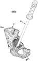
- FIG. 1 schematically a section of a human pelvic bone 10 is shown, in which a hip joint endoprosthesis is to be implanted.
- FIG. 2 represented an acetabulum 12, which is also referred to as hip joint or pelvic pan and in the anatomy formed by the pelvic bone 10 bony portion of the natural hip joint.
- a medical instrumentation designated overall by reference numeral 14 is used.
- this comprises a medical alignment instrument 16 with a shaped body 18 and a grip element 20.
- the grip element 20 can be used in particular as impactor 22. It comprises an elongated shaft 24, at the proximal end of a handle portion 26 is arranged or formed. An annular flange 30 projecting in the radial direction relative to a longitudinal axis 28 delimits the grip region 26 distally and, in particular, serves to prevent a hand of the surgeon holding the grip element 20 from slipping off in the distal direction.
- the shaft 24 comprises an elongated shaft sleeve 32 which is provided with a longitudinal bore extending coaxially to the longitudinal axis 28.
- an elongated inner shaft 34 is rotatably mounted and / or displaceable.
- a proximal end of the inner shaft 34 is rotatably coupled to an actuator 36 in the form of a knob 38.
- a proximal end face 40 of the knob 38 forms an at least partially flat face 42 which defines a plane 44 that is perpendicular to the longitudinal axis 28.
- a distal end 46 of the inner shaft 34 projects beyond a distal end 48 of the shaft sleeve 32 in the distal direction. Starting from the end 46, a short external thread section 50 is formed on the inner shaft 34.
- the molded body 18 is substantially cup-shaped and has a nearly constant wall thickness. On its underside 52 pointing in the distal direction, the shaped body 18 has a patient-specific bone abutment surface 54. This corresponds to the acetabulum 12 or at least to the specific for each patient Fossa 56 and / or the Incisura Acetabuli 58.
- the bone abutment surface 54 deviates from a spherical surface cutout.
- the bone abutment surface 54 on the shaped body 18 and / or the shaped body 18 are preferably produced by casting or 3D printing.
- a casting mold is formed on the basis of non-invasively determined bone contour data of the patient.
- the bone contour data may be from X-ray and / or magnetic resonance images of the patient's acetabulum 42.
- directly digitized X-ray images can be processed further to print data for a 3D printer, with which then the bone contact surface 54 can be printed on a support or as part of the molded body 18 together with this.
- a bone abutment surface 54 may then be formed which defines bone abutment surface contour data corresponding to the patient's non-invasively determined bone contour data.
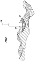
- a plurality of viewing edges 60, 62 and 64 in the form of recesses 112 or flats as surface areas with a viewing height, which adjoin the patient-individual bone abutment surface 54.
- a transition between the viewing edges 60, 62 and 64 and the bone abutment surface 54 is tangent-like.
- the viewing edges 60, 62 and 64 are each flat or substantially planar. The viewing edges 60 and 64 are nearly parallel to each other.
- a pin 68 is formed pointing in the proximal direction. It is provided with a blind hole 70, which is provided with an internally threaded portion 72 is. The female threaded portion 72 is formed corresponding to the male threaded portion 50.
- the blind hole 70 forms a coupling receptacle 74, which is formed corresponding to a coupling projection 76 formed by the end 46.
- the coupling receptacle 74 and the coupling projection 76 form first and second coupling elements 78 and 80 of a generally designated by the reference numeral 82 coupling means for temporarily coupling the molded body 18 with the handle member 20 in a coupling position such as in the FIGS. 1 and 3 is shown schematically.
- a rim portion 84 is formed, which engages over an edge 86 of the acetabulum 12 opposite the incisor acetabulum.
- fastening body 88 which is formed substantially cuboid.
- two fastener receptacles 90 are formed in the form of openings 92, which are produced as bores 94.
- fastener receiving longitudinal axes 96 extend parallel to the longitudinal axis 28.
- fixing pins can be introduced into the pelvic bone 10 by the fastening element receptacles 90, in order to fix the alignment instrument 16 on the acetabulum 12 and / or to fix referencing devices with marker elements to the position of the molding 18 on the pelvic bone 10 and thus its position in the To determine space with the help of a navigation system.
- the provision of the viewing edges 60, 62 and 64 allows an operator to check the positionally correct arrangement of the shaped body 18 in the acetabulum 12 by sight or with the aid of a tactile hook. Only if the shaped body 18 with the Bone abutment surface 54 rests flat against the bone surface 98 on the pelvic bone 10, the position and orientation of the shaped body 18 corresponds to the particular non-invasively determined bone contour data.
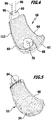
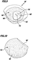
- FIGS. 6 to 10 a second embodiment of a designated by the reference numeral 18 'shaped body is shown. It forms part of the instrumentation 14. For the sake of clarity, identical parts and elements of the molding 18 'are provided with corresponding reference symbols which were used in the molding 18.
- the shaped body 18 ' is cup-shaped and has on its underside 52' on a bone abutment surface 54 ', which corresponds to a negative image of the fossa 56. Furthermore, recesses 112 'or flattenings in the form of flat view edges 60' and 62 'are provided on the shaped body 18', which are oriented substantially perpendicular to one another and respectively define planes that run essentially parallel to the longitudinal axis 28.
- the shaped body 18' On an upper side 66 'of the shaped body 18' is also a pin 68 'from which is provided with a blind hole 70' having an internally threaded portion 72 '.
- the shaped body 18 ' can be coupled in an analogous manner as the shaped body 18 with the handle member 20 in the manner described above.
- the viewing edges 60 'and 62' allow a surgeon to perform a visual inspection or examination in conjunction with a stylus instrument, such as a tactile hook, to see if the molding 18 'is accurately positioned in the acetabulum 12.
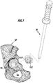
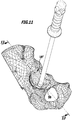
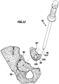
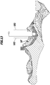
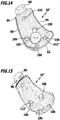
- FIGS. 11 to 15 3 is a schematic representation of a third embodiment of a molded article of the instrumentation 14, designated overall by reference numeral 18 ".
- the structure of the molding 18" essentially corresponds to the structure of the molding 18, so that identical reference symbols were used in the molding 18 "as in the molding 18.
- the shaped body 18 "differs from the shaped body 18 'in that it has a total of four recesses 112" in the form of apertures 100 arranged substantially uniformly around the journal 68.
- the apertures 100 define aperture longitudinal axes 102 that are substantially parallel to the longitudinal axis 28.
- the openings 100 are formed in the form of holes 104. Inner surfaces 106 of the bores 104 form viewing edges 108, which allow a direct view of the acetabulum 12.
- the openings 100 can be used by an operator, in particular as a viewing window, in order to check the optimum positioning of the shaped body 18 "on the acetabulum 12 on sight.
- further perforations 110 may be provided on the molded body 18 ", which may be formed outside the patient-specific bone abutment surface 54 in the form of bores.
- the moldings 18, 18 'and 18 can all be made of a plastic or a metal by casting or 3D printing.
Landscapes
- Health & Medical Sciences (AREA)
- Life Sciences & Earth Sciences (AREA)
- Orthopedic Medicine & Surgery (AREA)
- Surgery (AREA)
- Engineering & Computer Science (AREA)
- Heart & Thoracic Surgery (AREA)
- Veterinary Medicine (AREA)
- General Health & Medical Sciences (AREA)
- Transplantation (AREA)
- Public Health (AREA)
- Animal Behavior & Ethology (AREA)
- Biomedical Technology (AREA)
- Oral & Maxillofacial Surgery (AREA)
- Nuclear Medicine, Radiotherapy & Molecular Imaging (AREA)
- Physical Education & Sports Medicine (AREA)
- Vascular Medicine (AREA)
- Cardiology (AREA)
- Medical Informatics (AREA)
- Molecular Biology (AREA)
- Dentistry (AREA)
- Biophysics (AREA)
- Robotics (AREA)
- Prostheses (AREA)
- Surgical Instruments (AREA)
Applications Claiming Priority (2)
| Application Number | Priority Date | Filing Date | Title |
|---|---|---|---|
| DE201310112496 DE102013112496A1 (de) | 2013-11-13 | 2013-11-13 | Medizinisches Instrumentarium |
| PCT/EP2014/074252 WO2015071251A1 (de) | 2013-11-13 | 2014-11-11 | Medizinisches instrumentarium |
Publications (2)
| Publication Number | Publication Date |
|---|---|
| EP3073937A1 EP3073937A1 (de) | 2016-10-05 |
| EP3073937B1 true EP3073937B1 (de) | 2017-09-27 |
Family
ID=51894037
Family Applications (1)
| Application Number | Title | Priority Date | Filing Date |
|---|---|---|---|
| EP14796497.7A Active EP3073937B1 (de) | 2013-11-13 | 2014-11-11 | Medizinisches instrumentarium |
Country Status (5)
| Country | Link |
|---|---|
| US (1) | US20160250040A1 (enExample) |
| EP (1) | EP3073937B1 (enExample) |
| JP (1) | JP6574177B2 (enExample) |
| DE (1) | DE102013112496A1 (enExample) |
| WO (1) | WO2015071251A1 (enExample) |
Families Citing this family (9)
| Publication number | Priority date | Publication date | Assignee | Title |
|---|---|---|---|---|
| DE102013112497A1 (de) * | 2013-11-13 | 2015-05-13 | Aesculap Ag | Medizinisches Instrumentarium |
| US9414938B2 (en) * | 2014-09-12 | 2016-08-16 | Bullseye Hip Replacement, Llc | Devices and methods for hip replacement |
| EP4631446A3 (en) | 2015-02-13 | 2025-12-24 | Circinus Medical Technology, LLC | Electronic device for determining orientation of an instrument |
| WO2019036524A1 (en) | 2017-08-14 | 2019-02-21 | Scapa Flow, Llc | SYSTEM AND METHOD USING ENHANCED REALITY WITH FORMS ALIGNMENT FOR MEDICAL DEVICE INSTALLATION IN BONE |
| MA71211A (fr) | 2019-04-15 | 2025-04-30 | Circinus Medical Technologies LLC | Système d'étalonnage d'orientation pour capture d'image |
| EP3955841A4 (en) | 2019-04-15 | 2023-04-12 | Circinus Medical Technologies LLC | FIXING DEVICE FOR SECURING A MEDICAL ALIGNMENT DEVICE FOR ALIGNING A TOOL |
| EP4247254A4 (en) | 2020-11-19 | 2024-05-22 | Circinus Medical Technology LLC | Systems and methods for artificial intelligence based image analysis for placement of surgical appliance |
| WO2022169906A1 (en) | 2021-02-02 | 2022-08-11 | Circinus Medical Technology Llc | Systems and methods for simulating three- dimensional orientations of surgical hardware devices about an insertion point of an anatomy |
| AU2022256463A1 (en) | 2021-04-14 | 2023-11-02 | Circinus Medical Technology Llc | System and method for lidar-based anatomical mapping |
Family Cites Families (10)
| Publication number | Priority date | Publication date | Assignee | Title |
|---|---|---|---|---|
| DE10335388B4 (de) * | 2003-07-25 | 2006-06-22 | Aesculap Ag & Co. Kg | Satz chirurgischer Referenzierungsvorrichtungen |
| US9339278B2 (en) * | 2006-02-27 | 2016-05-17 | Biomet Manufacturing, Llc | Patient-specific acetabular guides and associated instruments |
| US8603180B2 (en) * | 2006-02-27 | 2013-12-10 | Biomet Manufacturing, Llc | Patient-specific acetabular alignment guides |
| US8992538B2 (en) * | 2008-09-30 | 2015-03-31 | DePuy Synthes Products, Inc. | Customized patient-specific acetabular orthopaedic surgical instrument and method of use and fabrication |
| US9498234B2 (en) * | 2009-12-29 | 2016-11-22 | Mobelife Nv | Customized surgical guides, methods for manufacturing and uses thereof |
| JP5412334B2 (ja) * | 2010-03-15 | 2014-02-12 | 鬼頭 縁 | 人工股関節置換手術支援システム |
| GB201009116D0 (en) * | 2010-06-01 | 2010-07-14 | Materialise Nv | Acetabular cup reamer |
| WO2011160008A1 (en) * | 2010-06-18 | 2011-12-22 | Howmedica Osteonics Corp. | Patient-specific total hip arthroplasty |
| US20140142578A1 (en) * | 2011-07-12 | 2014-05-22 | Materialise N.V. | Surgical instrument for the positioning of an alignment element |
| WO2013126416A1 (en) * | 2012-02-21 | 2013-08-29 | Biomet Manufacturing Corp. | Patient-specific acetabular guides and associated instruments |
-
2013
- 2013-11-13 DE DE201310112496 patent/DE102013112496A1/de not_active Withdrawn
-
2014
- 2014-11-11 JP JP2016529982A patent/JP6574177B2/ja active Active
- 2014-11-11 WO PCT/EP2014/074252 patent/WO2015071251A1/de not_active Ceased
- 2014-11-11 EP EP14796497.7A patent/EP3073937B1/de active Active
-
2016
- 2016-05-09 US US15/149,295 patent/US20160250040A1/en not_active Abandoned
Non-Patent Citations (1)
| Title |
|---|
| None * |
Also Published As
| Publication number | Publication date |
|---|---|
| WO2015071251A1 (de) | 2015-05-21 |
| JP6574177B2 (ja) | 2019-09-11 |
| US20160250040A1 (en) | 2016-09-01 |
| JP2016540557A (ja) | 2016-12-28 |
| EP3073937A1 (de) | 2016-10-05 |
| DE102013112496A1 (de) | 2015-05-13 |
Similar Documents
| Publication | Publication Date | Title |
|---|---|---|
| EP3073937B1 (de) | Medizinisches instrumentarium | |
| DE602005002962T2 (de) | Navigierte orthopädische Führungseinrichtung | |
| DE102006026913B4 (de) | Operationsnavigationsnachverfolgungseinrichtung, -system und -verfahren | |
| DE102004058725B4 (de) | Adapter für chirurgische Navigationsverfolgungsgeräte | |
| EP3151774B1 (de) | Medizinisches system | |
| DE602004013362T2 (de) | Einführelement für die minimalinvasive gelenkchirurgie | |
| DE69922023T2 (de) | Befestigungsgerät für medizinische bohrlehre | |
| DE4219939C2 (de) | Vorrichtung zur Ausrichtung, Positionierung und Führung von Bearbeitungswerkzeugen, Bearbeitungs- oder Meßvorrichtungen zur Bearbeitung einer knöchernen Struktur und Verfahren zur Erstellung dieser Vorrichtung | |
| DE112010003901B4 (de) | Patientenspezifische Ausrichtungsführung mit Schneidfläche und Laseranzeige | |
| DE602004000868T2 (de) | Universell einsetzbares Werkzeug zum Ausrichten | |
| DE69819567T2 (de) | Orthopädische Schnittführung und Hülse | |
| DE60024011T2 (de) | Vorrichtung zum Positionieren einer Prothese | |
| DE60320003T2 (de) | Führungsblock zur verwendung in der chirurgie | |
| DE112012003636T5 (de) | Patientenspezifische Kreuzbein-Darmbein-Führungen und damit in Zusammenhang stehende Verfahren | |
| DE69922047T2 (de) | Vorrichtung zur lokalizierung und resektion von knochen | |
| WO2003057087A2 (de) | Hilfsmittel zur implantation einer hüftgelenkendoprothese sowie verfahren für handhabung desselben | |
| EP2103270A1 (de) | System für navigations-unterstützte Schulteroperationen und Navigationsverfahren zur Positionierung navigierter Behandlungsgeräte bezüglich eines Knochens | |
| CH671873A5 (enExample) | ||
| DE102008052680A1 (de) | Vorrichtung zur kontrollierten Einstellung einer chirurgischen Positioniereinheit | |
| EP3128942A1 (de) | Positionierhilfe für chirurgische eingriffe | |
| DE102020116073A1 (de) | Medizintechnische Vorrichtung, Verfahren zum Registrieren eines Modelldatensatzes, Datenverarbeitungsprogramm und Programmspeichermedium | |
| EP3073968B1 (de) | Medizinisches instrumentarium | |
| DE102010035832A1 (de) | Instrumentarium zum Eindrehen eines Implantats in ein Bandscheibenfach | |
| DE10335388B4 (de) | Satz chirurgischer Referenzierungsvorrichtungen | |
| EP1543789B1 (de) | Universelles Instrument bzw. Instrumentensatz zur Navigation in der computergestützten Chirurgie |
Legal Events
| Date | Code | Title | Description |
|---|---|---|---|
| PUAI | Public reference made under article 153(3) epc to a published international application that has entered the european phase |
Free format text: ORIGINAL CODE: 0009012 |
|
| 17P | Request for examination filed |
Effective date: 20160513 |
|
| AK | Designated contracting states |
Kind code of ref document: A1 Designated state(s): AL AT BE BG CH CY CZ DE DK EE ES FI FR GB GR HR HU IE IS IT LI LT LU LV MC MK MT NL NO PL PT RO RS SE SI SK SM TR |
|
| AX | Request for extension of the european patent |
Extension state: BA ME |
|
| DAX | Request for extension of the european patent (deleted) | ||
| GRAP | Despatch of communication of intention to grant a patent |
Free format text: ORIGINAL CODE: EPIDOSNIGR1 |
|
| INTG | Intention to grant announced |
Effective date: 20170428 |
|
| GRAS | Grant fee paid |
Free format text: ORIGINAL CODE: EPIDOSNIGR3 |
|
| GRAA | (expected) grant |
Free format text: ORIGINAL CODE: 0009210 |
|
| AK | Designated contracting states |
Kind code of ref document: B1 Designated state(s): AL AT BE BG CH CY CZ DE DK EE ES FI FR GB GR HR HU IE IS IT LI LT LU LV MC MK MT NL NO PL PT RO RS SE SI SK SM TR |
|
| REG | Reference to a national code |
Ref country code: GB Ref legal event code: FG4D Free format text: NOT ENGLISH |
|
| REG | Reference to a national code |
Ref country code: CH Ref legal event code: EP |
|
| REG | Reference to a national code |
Ref country code: AT Ref legal event code: REF Ref document number: 931246 Country of ref document: AT Kind code of ref document: T Effective date: 20171015 |
|
| REG | Reference to a national code |
Ref country code: IE Ref legal event code: FG4D Free format text: LANGUAGE OF EP DOCUMENT: GERMAN |
|
| REG | Reference to a national code |
Ref country code: DE Ref legal event code: R096 Ref document number: 502014005624 Country of ref document: DE |
|
| REG | Reference to a national code |
Ref country code: FR Ref legal event code: PLFP Year of fee payment: 4 |
|
| PG25 | Lapsed in a contracting state [announced via postgrant information from national office to epo] |
Ref country code: LT Free format text: LAPSE BECAUSE OF FAILURE TO SUBMIT A TRANSLATION OF THE DESCRIPTION OR TO PAY THE FEE WITHIN THE PRESCRIBED TIME-LIMIT Effective date: 20170927 Ref country code: SE Free format text: LAPSE BECAUSE OF FAILURE TO SUBMIT A TRANSLATION OF THE DESCRIPTION OR TO PAY THE FEE WITHIN THE PRESCRIBED TIME-LIMIT Effective date: 20170927 Ref country code: FI Free format text: LAPSE BECAUSE OF FAILURE TO SUBMIT A TRANSLATION OF THE DESCRIPTION OR TO PAY THE FEE WITHIN THE PRESCRIBED TIME-LIMIT Effective date: 20170927 Ref country code: NO Free format text: LAPSE BECAUSE OF FAILURE TO SUBMIT A TRANSLATION OF THE DESCRIPTION OR TO PAY THE FEE WITHIN THE PRESCRIBED TIME-LIMIT Effective date: 20171227 Ref country code: HR Free format text: LAPSE BECAUSE OF FAILURE TO SUBMIT A TRANSLATION OF THE DESCRIPTION OR TO PAY THE FEE WITHIN THE PRESCRIBED TIME-LIMIT Effective date: 20170927 |
|
| REG | Reference to a national code |
Ref country code: NL Ref legal event code: MP Effective date: 20170927 |
|
| REG | Reference to a national code |
Ref country code: LT Ref legal event code: MG4D |
|
| PG25 | Lapsed in a contracting state [announced via postgrant information from national office to epo] |
Ref country code: RS Free format text: LAPSE BECAUSE OF FAILURE TO SUBMIT A TRANSLATION OF THE DESCRIPTION OR TO PAY THE FEE WITHIN THE PRESCRIBED TIME-LIMIT Effective date: 20170927 Ref country code: BG Free format text: LAPSE BECAUSE OF FAILURE TO SUBMIT A TRANSLATION OF THE DESCRIPTION OR TO PAY THE FEE WITHIN THE PRESCRIBED TIME-LIMIT Effective date: 20171227 Ref country code: GR Free format text: LAPSE BECAUSE OF FAILURE TO SUBMIT A TRANSLATION OF THE DESCRIPTION OR TO PAY THE FEE WITHIN THE PRESCRIBED TIME-LIMIT Effective date: 20171228 Ref country code: LV Free format text: LAPSE BECAUSE OF FAILURE TO SUBMIT A TRANSLATION OF THE DESCRIPTION OR TO PAY THE FEE WITHIN THE PRESCRIBED TIME-LIMIT Effective date: 20170927 |
|
| PG25 | Lapsed in a contracting state [announced via postgrant information from national office to epo] |
Ref country code: NL Free format text: LAPSE BECAUSE OF FAILURE TO SUBMIT A TRANSLATION OF THE DESCRIPTION OR TO PAY THE FEE WITHIN THE PRESCRIBED TIME-LIMIT Effective date: 20170927 |
|
| PG25 | Lapsed in a contracting state [announced via postgrant information from national office to epo] |
Ref country code: ES Free format text: LAPSE BECAUSE OF FAILURE TO SUBMIT A TRANSLATION OF THE DESCRIPTION OR TO PAY THE FEE WITHIN THE PRESCRIBED TIME-LIMIT Effective date: 20170927 Ref country code: CZ Free format text: LAPSE BECAUSE OF FAILURE TO SUBMIT A TRANSLATION OF THE DESCRIPTION OR TO PAY THE FEE WITHIN THE PRESCRIBED TIME-LIMIT Effective date: 20170927 Ref country code: RO Free format text: LAPSE BECAUSE OF FAILURE TO SUBMIT A TRANSLATION OF THE DESCRIPTION OR TO PAY THE FEE WITHIN THE PRESCRIBED TIME-LIMIT Effective date: 20170927 |
|
| PG25 | Lapsed in a contracting state [announced via postgrant information from national office to epo] |
Ref country code: IT Free format text: LAPSE BECAUSE OF FAILURE TO SUBMIT A TRANSLATION OF THE DESCRIPTION OR TO PAY THE FEE WITHIN THE PRESCRIBED TIME-LIMIT Effective date: 20170927 Ref country code: EE Free format text: LAPSE BECAUSE OF FAILURE TO SUBMIT A TRANSLATION OF THE DESCRIPTION OR TO PAY THE FEE WITHIN THE PRESCRIBED TIME-LIMIT Effective date: 20170927 Ref country code: SK Free format text: LAPSE BECAUSE OF FAILURE TO SUBMIT A TRANSLATION OF THE DESCRIPTION OR TO PAY THE FEE WITHIN THE PRESCRIBED TIME-LIMIT Effective date: 20170927 Ref country code: SM Free format text: LAPSE BECAUSE OF FAILURE TO SUBMIT A TRANSLATION OF THE DESCRIPTION OR TO PAY THE FEE WITHIN THE PRESCRIBED TIME-LIMIT Effective date: 20170927 Ref country code: IS Free format text: LAPSE BECAUSE OF FAILURE TO SUBMIT A TRANSLATION OF THE DESCRIPTION OR TO PAY THE FEE WITHIN THE PRESCRIBED TIME-LIMIT Effective date: 20180127 |
|
| REG | Reference to a national code |
Ref country code: DE Ref legal event code: R097 Ref document number: 502014005624 Country of ref document: DE |
|
| PG25 | Lapsed in a contracting state [announced via postgrant information from national office to epo] |
Ref country code: MC Free format text: LAPSE BECAUSE OF FAILURE TO SUBMIT A TRANSLATION OF THE DESCRIPTION OR TO PAY THE FEE WITHIN THE PRESCRIBED TIME-LIMIT Effective date: 20170927 |
|
| PG25 | Lapsed in a contracting state [announced via postgrant information from national office to epo] |
Ref country code: LI Free format text: LAPSE BECAUSE OF NON-PAYMENT OF DUE FEES Effective date: 20171130 Ref country code: CH Free format text: LAPSE BECAUSE OF NON-PAYMENT OF DUE FEES Effective date: 20171130 Ref country code: DK Free format text: LAPSE BECAUSE OF FAILURE TO SUBMIT A TRANSLATION OF THE DESCRIPTION OR TO PAY THE FEE WITHIN THE PRESCRIBED TIME-LIMIT Effective date: 20170927 |
|
| PLBE | No opposition filed within time limit |
Free format text: ORIGINAL CODE: 0009261 |
|
| STAA | Information on the status of an ep patent application or granted ep patent |
Free format text: STATUS: NO OPPOSITION FILED WITHIN TIME LIMIT |
|
| PG25 | Lapsed in a contracting state [announced via postgrant information from national office to epo] |
Ref country code: PL Free format text: LAPSE BECAUSE OF FAILURE TO SUBMIT A TRANSLATION OF THE DESCRIPTION OR TO PAY THE FEE WITHIN THE PRESCRIBED TIME-LIMIT Effective date: 20170927 Ref country code: LU Free format text: LAPSE BECAUSE OF NON-PAYMENT OF DUE FEES Effective date: 20171111 |
|
| REG | Reference to a national code |
Ref country code: BE Ref legal event code: MM Effective date: 20171130 |
|
| 26N | No opposition filed |
Effective date: 20180628 |
|
| REG | Reference to a national code |
Ref country code: IE Ref legal event code: MM4A |
|
| PG25 | Lapsed in a contracting state [announced via postgrant information from national office to epo] |
Ref country code: MT Free format text: LAPSE BECAUSE OF FAILURE TO SUBMIT A TRANSLATION OF THE DESCRIPTION OR TO PAY THE FEE WITHIN THE PRESCRIBED TIME-LIMIT Effective date: 20170927 |
|
| PG25 | Lapsed in a contracting state [announced via postgrant information from national office to epo] |
Ref country code: IE Free format text: LAPSE BECAUSE OF NON-PAYMENT OF DUE FEES Effective date: 20171111 |
|
| PG25 | Lapsed in a contracting state [announced via postgrant information from national office to epo] |
Ref country code: BE Free format text: LAPSE BECAUSE OF NON-PAYMENT OF DUE FEES Effective date: 20171130 Ref country code: SI Free format text: LAPSE BECAUSE OF FAILURE TO SUBMIT A TRANSLATION OF THE DESCRIPTION OR TO PAY THE FEE WITHIN THE PRESCRIBED TIME-LIMIT Effective date: 20170927 |
|
| PG25 | Lapsed in a contracting state [announced via postgrant information from national office to epo] |
Ref country code: HU Free format text: LAPSE BECAUSE OF FAILURE TO SUBMIT A TRANSLATION OF THE DESCRIPTION OR TO PAY THE FEE WITHIN THE PRESCRIBED TIME-LIMIT; INVALID AB INITIO Effective date: 20141111 |
|
| PG25 | Lapsed in a contracting state [announced via postgrant information from national office to epo] |
Ref country code: CY Free format text: LAPSE BECAUSE OF FAILURE TO SUBMIT A TRANSLATION OF THE DESCRIPTION OR TO PAY THE FEE WITHIN THE PRESCRIBED TIME-LIMIT Effective date: 20170927 |
|
| PG25 | Lapsed in a contracting state [announced via postgrant information from national office to epo] |
Ref country code: MK Free format text: LAPSE BECAUSE OF FAILURE TO SUBMIT A TRANSLATION OF THE DESCRIPTION OR TO PAY THE FEE WITHIN THE PRESCRIBED TIME-LIMIT Effective date: 20170927 |
|
| PG25 | Lapsed in a contracting state [announced via postgrant information from national office to epo] |
Ref country code: TR Free format text: LAPSE BECAUSE OF FAILURE TO SUBMIT A TRANSLATION OF THE DESCRIPTION OR TO PAY THE FEE WITHIN THE PRESCRIBED TIME-LIMIT Effective date: 20170927 |
|
| PG25 | Lapsed in a contracting state [announced via postgrant information from national office to epo] |
Ref country code: PT Free format text: LAPSE BECAUSE OF FAILURE TO SUBMIT A TRANSLATION OF THE DESCRIPTION OR TO PAY THE FEE WITHIN THE PRESCRIBED TIME-LIMIT Effective date: 20170927 |
|
| PG25 | Lapsed in a contracting state [announced via postgrant information from national office to epo] |
Ref country code: AL Free format text: LAPSE BECAUSE OF FAILURE TO SUBMIT A TRANSLATION OF THE DESCRIPTION OR TO PAY THE FEE WITHIN THE PRESCRIBED TIME-LIMIT Effective date: 20170927 |
|
| REG | Reference to a national code |
Ref country code: AT Ref legal event code: MM01 Ref document number: 931246 Country of ref document: AT Kind code of ref document: T Effective date: 20191111 |
|
| PG25 | Lapsed in a contracting state [announced via postgrant information from national office to epo] |
Ref country code: AT Free format text: LAPSE BECAUSE OF NON-PAYMENT OF DUE FEES Effective date: 20191111 |
|
| P01 | Opt-out of the competence of the unified patent court (upc) registered |
Effective date: 20230726 |
|
| PGFP | Annual fee paid to national office [announced via postgrant information from national office to epo] |
Ref country code: DE Payment date: 20251118 Year of fee payment: 12 |
|
| PGFP | Annual fee paid to national office [announced via postgrant information from national office to epo] |
Ref country code: GB Payment date: 20251120 Year of fee payment: 12 |
|
| PGFP | Annual fee paid to national office [announced via postgrant information from national office to epo] |
Ref country code: FR Payment date: 20251120 Year of fee payment: 12 |