EP3072597B1 - Abgabevorrichtung für ein fluid - Google Patents
Abgabevorrichtung für ein fluid Download PDFInfo
- Publication number
- EP3072597B1 EP3072597B1 EP16152682.7A EP16152682A EP3072597B1 EP 3072597 B1 EP3072597 B1 EP 3072597B1 EP 16152682 A EP16152682 A EP 16152682A EP 3072597 B1 EP3072597 B1 EP 3072597B1
- Authority
- EP
- European Patent Office
- Prior art keywords
- fluid
- chamber
- valve
- valve element
- stroke
- Prior art date
- Legal status (The legal status is an assumption and is not a legal conclusion. Google has not performed a legal analysis and makes no representation as to the accuracy of the status listed.)
- Active
Links
Images



Classifications
-
- B—PERFORMING OPERATIONS; TRANSPORTING
- B05—SPRAYING OR ATOMISING IN GENERAL; APPLYING FLUENT MATERIALS TO SURFACES, IN GENERAL
- B05C—APPARATUS FOR APPLYING FLUENT MATERIALS TO SURFACES, IN GENERAL
- B05C11/00—Component parts, details or accessories not specifically provided for in groups B05C1/00 - B05C9/00
- B05C11/10—Storage, supply or control of liquid or other fluent material; Recovery of excess liquid or other fluent material
- B05C11/1002—Means for controlling supply, i.e. flow or pressure, of liquid or other fluent material to the applying apparatus, e.g. valves
- B05C11/1026—Valves
- B05C11/1028—Lift valves
-
- B—PERFORMING OPERATIONS; TRANSPORTING
- B05—SPRAYING OR ATOMISING IN GENERAL; APPLYING FLUENT MATERIALS TO SURFACES, IN GENERAL
- B05B—SPRAYING APPARATUS; ATOMISING APPARATUS; NOZZLES
- B05B11/00—Single-unit hand-held apparatus in which flow of contents is produced by the muscular force of the operator at the moment of use
- B05B11/0005—Components or details
- B05B11/0062—Outlet valves actuated by the pressure of the fluid to be sprayed
- B05B11/0064—Lift valves
- B05B11/0067—Lift valves having a valve seat located downstream the valve element
-
- B—PERFORMING OPERATIONS; TRANSPORTING
- B05—SPRAYING OR ATOMISING IN GENERAL; APPLYING FLUENT MATERIALS TO SURFACES, IN GENERAL
- B05B—SPRAYING APPARATUS; ATOMISING APPARATUS; NOZZLES
- B05B11/00—Single-unit hand-held apparatus in which flow of contents is produced by the muscular force of the operator at the moment of use
- B05B11/0005—Components or details
- B05B11/0062—Outlet valves actuated by the pressure of the fluid to be sprayed
- B05B11/0072—A valve member forming part of an outlet opening
-
- B—PERFORMING OPERATIONS; TRANSPORTING
- B05—SPRAYING OR ATOMISING IN GENERAL; APPLYING FLUENT MATERIALS TO SURFACES, IN GENERAL
- B05B—SPRAYING APPARATUS; ATOMISING APPARATUS; NOZZLES
- B05B11/00—Single-unit hand-held apparatus in which flow of contents is produced by the muscular force of the operator at the moment of use
- B05B11/01—Single-unit hand-held apparatus in which flow of contents is produced by the muscular force of the operator at the moment of use characterised by the means producing the flow
- B05B11/10—Pump arrangements for transferring the contents from the container to a pump chamber by a sucking effect and forcing the contents out through the dispensing nozzle
- B05B11/1001—Piston pumps
- B05B11/1016—Piston pumps the outlet valve having a valve seat located downstream a movable valve element controlled by a pressure actuated controlling element
Definitions
- the invention relates to a dispensing device for a fluid with a fluid channel and a chamber arrangement in which a valve element is movably arranged, which cooperates with a dispensing opening, the chamber arrangement having at least one sealing element which seals against the valve element via a first predetermined stroke of the valve element. and wherein the sealing element closes a liquid path from the chamber arrangement to the discharge opening via the first stroke.
- Such a delivery device is, for example, from EP 0 686 433 A2 known.
- an atomized fluid is to be released under pressure.
- EP 0 688 608 A1 describes an atomizer for manually operated pumps.
- the pump has a fluid channel and a chamber arrangement.
- a valve element is arranged movably in the chamber arrangement and cooperates with a discharge opening.
- the chamber arrangement has at least one sealing element which seals against the valve element via a stroke of the valve element.
- WO 99/04906 A1 relates to a push button with a movable nozzle for dispensing fluids under pressure.
- the associated pump has a fluid channel and a chamber arrangement.
- a valve element is arranged movably in the chamber arrangement and cooperates with a discharge opening.
- the chamber arrangement has at least one sealing lip which seals against the valve element via a stroke of the valve element.
- Dispensing devices of this type are used, for example, to dispense fluids which contain medical or cosmetic active ingredient solutions.
- the fluids should be placed in the nose, mouth or eyes of a user.
- the fluids are transported through the fluid channel and the chamber arrangement to the discharge opening. That in the Chamber arrangement movably arranged valve element is used for the controlled delivery of a predetermined amount of fluid.
- the valve element For the purpose of dispensing a predetermined amount of fluid, the valve element cooperates with the dispensing opening.
- the valve element In a closed state, the valve element can, for example, seal the discharge opening against leakage of the fluid.
- a stroke of the valve element brings it into an open state. In the open state, a quantity of fluid can now emerge from the discharge opening.
- the invention is therefore based on the object of providing a dispensing device for a fluid which enables low-contamination and drop-shaped dispensing of the fluid.
- this object is achieved in a dispensing device of the type mentioned at the outset in that the valve element has a second predetermined stroke of the valve element seals the discharge opening, the sealing element closes the liquid path from the chamber arrangement to the discharge opening via the second stroke, the valve element comprising a cylinder which seals the discharge opening by a positive fit.
- valve element An actuation of the valve element now has no consequence that the fluid can exit the dispensing opening even with a slight stroke of the valve element. So that the fluid is not accelerated in the slight opening of the valve element. Over the entire first stroke, the sealing element ensures that the fluid cannot pass through the valve element. As a result, a certain amount of fluid accumulates in the fluid channel and chamber arrangement as a result of the first predetermined stroke. It can also be avoided that contamination continues beyond the valve element into the chamber arrangement or the fluid channel.
- the sealing element closes a liquid path from the chamber arrangement to the dispensing opening via the first stroke.
- the fluid channel opens into the chamber arrangement.
- the path of the fluid through the fluid channel continues in the liquid path in the chamber arrangement.
- This liquid path is interrupted by the sealing element over the first stroke of the valve element. The interruption of the liquid path leads to the fluid being retained in the chamber arrangement. A certain amount of fluid accumulates in the chamber assembly, but it cannot advance to the dispensing opening.
- the valve element seals the discharge opening via a second predetermined stroke of the valve element, the sealing element closing the liquid path from the chamber arrangement to the discharge opening via the second stroke.
- the valve element thus interacts with the dispensing opening in such a way that it seals it in a closed state.
- the valve element is therefore at least partially received in the nozzle chamber. In the closed state of the valve element, the penetration of foreign substances into the nozzle chamber can be avoided. Contamination of the dispenser is avoided.
- With a stroke of the valve element that is greater than the second Stroke the valve element clears the discharge opening. Fluid in the nozzle chamber can exit through the discharge opening. In this state, however, leakage of the fluid through the discharge opening should still be avoided.
- the sealing element closes the liquid path from the chamber arrangement to the dispensing opening via the second stroke. No fluid can get into the nozzle chamber from the valve chamber. As soon as the stroke of the valve element has exceeded the first predetermined stroke, the sealing element releases the liquid path between the valve chamber and the nozzle chamber. Controlled and drop-shaped delivery of the fluid is now possible.
- the sealing element clears the liquid path when the valve element is moved more than the first stroke. After a certain amount of fluid has accumulated in the chamber arrangement, the stroke of the valve element exceeds the first stroke. The sealing element no longer seals against the valve element. The fluid path for the fluid is released. The fluid can now over the liquid path is transported to the dispensing opening. The amount of fluid can be dispensed in the form of a drop.
- the valve element has a space, in particular at least one groove, which forms part of the liquid path.
- the fluid is transported along the valve element on the liquid path from the chamber arrangement to the discharge opening.
- the space is only released when the stroke of the valve element has exceeded the first predetermined stroke. This ensures that the fluid does not have to pass a narrow liquid path. An undesired acceleration of the fluid when passing through the valve element can thus be avoided.
- a controlled dispensing of the fluid is made possible. An uncontrolled splashing of the fluid out of the discharge opening is avoided.
- the space that forms part of the liquid path can in particular be designed as at least one groove. A controlled transport of the fluid is possible. Penetration of larger foreign matter particles can be avoided. Contamination of the liquid path can thus be kept low.
- the chamber arrangement has a valve chamber and a nozzle chamber, the sealing element sealing the nozzle chamber with respect to the valve chamber.
- a spatial division of the chamber arrangement is achieved. Fluid accumulates in the valve chamber over the first predetermined stroke of the valve element. Due to the sealing element, the fluid cannot leave the valve chamber via the first stroke of the valve element. As soon as the stroke of the valve element exceeds the first stroke, the fluid path is released. The fluid can be transported from the valve chamber into the nozzle chamber. Due to the spatial separation of the valve chamber and nozzle chamber, it is another barrier against this Penetration of foreign substances created. The contamination of the dispenser can be kept low.
- a valve seat is arranged between the valve chamber and the nozzle chamber, in which the valve element is movably arranged and which has the sealing element.
- the valve seat serves for the spatial separation between the valve chamber and the nozzle chamber.
- it serves to accommodate the valve element.
- the valve seat now advantageously also has the sealing element; this can be arranged, for example, between the valve element and the valve seat. It is possible to design the valve seat and sealing element in one piece.
- the fluid path is arranged between the sealing element or valve seat and valve element.
- the liquid path opens into the nozzle chamber, the nozzle chamber having the discharge opening.
- the fluid is transported along the liquid path.
- the amount of fluid that has accumulated in the nozzle chamber first passes through the space of the valve element. After the valve element has been passed through in this way, the fluid continues to be transported via the liquid path into the nozzle chamber.
- the nozzle chamber has a larger volume than the room. When the fluid was transported from the valve chamber into the room, the fluid was accelerated. The volume of the room is smaller than the volume of the valve chamber. When the fluid exits the space into the nozzle chamber, the fluid is braked by expansion into the volume of the nozzle chamber. The amount of fluid that has entered the nozzle chamber in this way can then exit the dispensing opening in a controlled manner.
- the nozzle chamber has the discharge opening. A drop-shaped delivery of the fluid is made possible.
- the sealing element is designed as at least one sealing lip and bears against the valve element via the first stroke.
- a reliable seal between the sealing element and valve element and between the valve chamber and nozzle chamber is achieved.
- With a stroke of the valve element that is greater than the first stroke the contact of the sealing element on the valve element ends.
- the space occurs between the sealing element and the valve element.
- a through opening between the valve chamber and the nozzle chamber is thus opened.
- the amount of fluid accumulated in the valve chamber can pass through the sealing element and enter the room. The fluid is transported from the valve chamber into the nozzle chamber and finally to the discharge opening.
- the first stroke forms a multiple of the second stroke.
- a sufficient amount of fluid for droplet formation can collect in the valve chamber.
- the discharge opening is completely cleared by the valve element.
- the transport of the fluid through a narrow opening between the valve element and the discharge opening can be avoided. Acceleration of the fluid during dispensing is avoided. A drop-shaped delivery of the fluid is made possible.
- Fig. 1 shows a dispenser 1 for a fluid.
- the dispensing device 1 has a head base part 2, which is arranged on a snap-on 3.
- a cone 4 extends from the head base part 2 in an axial direction through the snap-on 3 into a housing 5.
- the cone 4 cooperates with a housing spring 6 in the housing 5.
- the cone 4 has a fluid channel 7.
- the fluid channel 7 extends in the axial direction toward the head base part 2.
- the fluid channel 7 continues in the head base part 2 into a liner channel 8.
- This liner channel 8 is arranged between the head base part 2 and a liner 9.
- the liner channel 8 opens into a chamber arrangement 10.
- This chamber arrangement 10 has a valve chamber 11.
- a space 12 leaves a liquid path from the valve chamber 11 to a nozzle chamber 13.
- the nozzle chamber 13 has a discharge opening 14.
- the discharge opening 14 is designed in the form of a spherical cap 15.
- a valve element 16 is arranged in the chamber arrangement 10. This has a first sealing lip 17 in the valve chamber 11. At one end of the valve element 16 opposite the first sealing lip 17, the valve element 16 is designed in the form of a cylinder 18.
- the valve chamber 11 is divided into two areas by the first sealing lip 17.
- the fluid path of the liner channel 8 continues into a first area of the valve chamber 11. This first area of the valve chamber 11 is spatially separated from a second area of the valve chamber 11 by means of the first sealing lip 17.
- the second area of the valve chamber 11 has a head spring 19.
- a valve seat 20 is arranged between the valve chamber 11 and the nozzle chamber 13.
- This valve seat 20 has at least one crown 21.
- the Crown 21 is arranged at the transition from liner channel 8 to valve chamber 11. Furthermore, the valve seat 20 has a sealing element 22.
- FIGS 1 to 4 The embodiment of the dispensing device 1 just described is shown in FIGS 1 to 4 shown. Identical features are provided with identical reference symbols.
- Fig. 1 represents a state of the dispensing device 1 in which the valve element 16 is arranged in a closed state.
- Fig. 3 shows the same dispensing device 1, in which the valve element 16 is arranged in an open state.
- a user moves the head base part 2 in the axial direction towards the snap-on 3.
- the cone 4 is moved inside the housing 5 against the spring force of the housing spring 6.
- the volume in a pump chamber of the housing 5 is reduced.
- the pump chamber is formed by the space surrounding the housing spring 6.
- the amount of fluid delivered is determined by a stroke of the cone 4 within the pump chamber. This enables the metering of a predetermined amount of fluid.
- the resulting overpressure displaces the fluid from the pump chamber into the fluid channel 7.
- the fluid is transported in an axial direction along the fluid channel 7.
- the transport of the fluid continues in the liner 9 through the liner channel 8.
- the fluid finally passes through the crown 21 and reaches the valve chamber 11.
- valve chamber 11 There is a certain accumulation of fluid in the valve chamber 11. The more fluid that accumulates in the valve chamber 11, the greater the pressure of the fluid on the valve element 16.
- the valve chamber 11 is there sealed by means of the first sealing lip 17 from the region of the valve chamber 11 in which the head spring 19 is arranged. Furthermore, the valve chamber 11 is sealed off from the nozzle chamber 13 by means of the sealing element 22. The fluid collecting in the valve chamber 11 thus displaces the valve element 16 against the spring force of the top spring 19.
- the cylinder 18 seals the dispensing opening 14. This seal is achieved, for example, by a form fit. The possibility of contamination of the nozzle chamber 13 can be avoided.
- the fluid entering the valve chamber 11 now displaces the valve element 16 against the spring force of the top spring 19. This results in a stroke of the valve element 16.
- the cylinder 18 opens the discharge opening 14.
- the sealing element 22 is still in a fluid-tight manner against the valve element 16.
- the fluid in the valve chamber 11 cannot enter the space 12.
- the space 12 is designed here as a groove in the valve element 16.
- the stroke of the valve element 16 continues until the sealing element 22 reaches the space 12.
- the valve element 16 has now covered a first stroke. During this first stroke, the sealing element 22 seals against the valve element 16.
- the sealing element 22 As soon as the stroke of the valve element 16 exceeds the first predetermined stroke, there is an overlap of the sealing element 22 with the space 12. The sealing element 22 now releases a liquid path into the space 12. The fluid in the valve chamber 11 can enter the space 12. The fluid is transported through the space 12 into the nozzle chamber 13.
- the first stroke is designed as a multiple of the second stroke. This will achieved that the cylinder 18 has completely released the discharge opening 14 after a stroke that is greater than the first stroke.
- the volume of the valve chamber 11 is greater than the volume of the space 12.
- the fluid is accelerated when it enters the space 12. This acceleration is undesirable because a controlled drop-shaped delivery of the fluid is desired.
- the nozzle chamber 13 has a larger volume than the space 12.
- the nozzle chamber 13 is also arranged in the transport direction of the fluid after the space 12. The fluid accelerated in the space 12 can thus expand in the nozzle chamber 13. This slows down the fluid.
- the nozzle chamber 13 then has the discharge opening 14. The fluid can emerge from the discharge opening 14 along the cap 15 in the form of drops.
- this enables the drop-shaped delivery of the fluid by the delivery device 1.
- contamination of the dispensing device 1 with foreign substances can be largely avoided.
- the contamination of the dispensing device 1 is achieved on the one hand by sealing the dispensing opening 14 by means of the cylinder 18 in a closed state of the valve element 16. Furthermore, the spatial separation of the nozzle chamber 13 and the valve chamber 11 by the valve seat 20 serves this purpose. With a stroke that is less than the first stroke, the sealing element 22 prevents penetration of foreign matter from the nozzle chamber 13 into the valve chamber 11. With a stroke that is greater than the first stroke, the sealing element 22 clears the liquid path. Fluid from the valve chamber 11 then enters the chamber 12 and then the nozzle chamber 13. Foreign matter possibly located in the nozzle chamber 13 is thus washed out. They cannot get into the valve chamber 11 against the fluid flow through the space 12. A Contamination of the dispensing device 1 can thus be largely avoided.
Landscapes
- Closures For Containers (AREA)
- Containers And Packaging Bodies Having A Special Means To Remove Contents (AREA)
- Coating Apparatus (AREA)
- Infusion, Injection, And Reservoir Apparatuses (AREA)
Description
- Die Erfindung betrifft eine Abgabevorrichtung für ein Fluid mit einem Fluidkanal und einer Kammeranordnung, in der ein Ventilelement bewegbar angeordnet ist, das mit einer Abgabeöffnung zusammenwirkt, wobei die Kammeranordnung mindestens ein Dichtelement aufweist, das über einen ersten vorbestimmten Hub des Ventilelements gegenüber dem Ventilelement abdichtet, und wobei das Dichtelement über den ersten Hub einen Flüssigkeitspfad von der Kammeranordnung zu der Abgabeöffnung verschließt.
- Eine derartige Abgabevorrichtung ist beispielsweise aus
EP 0 686 433 A2 bekannt. Hier soll ein zerstäubtes Fluid unter Druck abgegeben werden. -
EP 0 688 608 A1 beschreibt einen Zerstäuber für händisch betriebene Pumpen. Die Pumpe weist einen Fluidkanal und eine Kammeranordnung auf. In der Kammeranordnung ist ein Ventilelement bewegbar angeordnet, das mit einer Abgabeöffnung zusammenwirkt. Die Kammeranordnung weist mindestens ein Dichtelement auf, das über einen Hub des Ventilelements gegenüber dem Ventilelement abdichtet. -
WO 99/04906 A1 - Derartige Abgabevorrichtungen dienen beispielsweise der Abgabe von Fluiden, die medizinische oder kosmetische Wirkstofflösungen enthalten. Die Fluide sollen beispielsweise in Nase, Mund oder Augen eines Anwenders verbracht werden. Hierzu werden die Fluide durch den Fluidkanal und die Kammeranordnung zu der Abgabeöffnung transportiert. Das in der Kammeranordnung bewegbar angeordnete Ventilelement dient der kontrollierten Abgabe einer vorbestimmten Fluidmenge.
- Zum Zweck der Abgabe einer vorbestimmten Fluidmenge wirkt das Ventilelement mit der Abgabeöffnung zusammen. In einem geschlossenen Zustand kann das Ventilelement dabei beispielsweise die Abgabeöffnung gegen ein Austreten des Fluides abdichten. Ein Hub des Ventilelements überführt dieses in einen geöffneten Zustand. In dem geöffneten Zustand kann nun eine Fluidmenge aus der Abgabeöffnung austreten.
- Insbesondere bei der Verwendung der Abgabevorrichtung als "Tropfer" ergibt sich dabei jedoch folgendes Problem. Ein lediglich geringfügiger Hub des Ventilelements hat zur Folge, dass das Fluid unter hoher Geschwindigkeit aus der Abgabeöffnung heraustritt. Dies ist einer kontrollierten und vorbestimmten tropfenförmigen Abgabe des Fluid abträglich. Insbesondere eine Verwendung der Abgabevorrichtung für Augentropfen käme hier nicht in Betracht.
- Die Verwendung für medizinische Fluide stellt eine weitere Anforderung an die Abgabevorrichtung. Hier muss eine Kontamination des Fluides durch Fremdstoffe zwischen dem Ventilelement und der Abgabeöffnung möglichst vermieden werden. Eine derartige Kontamination darf sich insbesondere nicht in den Fluidkanal fortsetzen. Die Abgabevorrichtung würde hierdurch unbrauchbar für die Verwendung für medizinische Fluide.
- Der Erfindung liegt daher die Aufgabe zugrunde, eine Abgabevorrichtung für ein Fluid bereitzustellen, die eine kontaminationsarme und tropfenförmige Abgabe des Fluides ermöglicht.
- Erfindungsgemäß wird diese Aufgabe bei einer Abgabevorrichtung der eingangs genannten Art dadurch gelöst, dass das Ventilelement über einen zweiten vorbestimmten Hub des Ventilelements die Abgabeöffnung abdichtet, wobei das Dichtelement über den zweiten Hub den Flüssigkeitspfad von der Kammeranordnung zu der Abgabeöffnung verschließt, wobei das Ventilelement einen Zylinder umfasst, der die Abgabeöffnung durch einen Formschluss abdichtet.
- Eine Betätigung des Ventilelements hat nunmehr nicht zur Folge, dass das Fluid bereits bei einem geringfügigen Hub des Ventilelements aus der Abgabeöffnung austreten kann. Damit wird das Fluid auch nicht in der geringfügigen Öffnung des Ventilelements beschleunigt. Über den gesamten ersten Hub sorgt das Dichtelement dafür, dass das Fluid das Ventilelement nicht passieren kann. Folglich kommt es durch den ersten vorbestimmten Hub zur Ansammlung einer gewissen Fluidmenge in Fluidkanal und Kammeranordnung. Es kann ebenso vermieden werden, dass sich Kontaminationen über das Ventilelement hinaus in die Kammeranordnung oder den Fluidkanal fortsetzen.
- Das Dichtelement verschließt über den ersten Hub einen Flüssigkeitspfad von der Kammeranordnung zu der Abgabeöffnung. Der Fluidkanal mündet in die Kammeranordnung. Der Weg des Fluides durch den Fluidkanal setzt sich in dem Flüssigkeitspfad in der Kammeranordnung fort. Dieser Flüssigkeitspfad wird durch das Dichtelement über den ersten Hub des Ventilelements unterbrochen. Die Unterbrechung des Flüssigkeitspfads führt dazu, dass das Fluid in der Kammeranordnung zurückgehalten wird. Es kommt zu einer Ansammlung einer gewissen Fluidmenge in der Kammeranordnung, die jedoch nicht zur Abgabeöffnung vordringen kann.
- Das Ventilelement dichtet über einen zweiten vorbestimmten Hub des Ventilelements die Abgabeöffnung ab, wobei das Dichtelement über den zweiten Hub den Flüssigkeitspfad von der Kammeranordnung zu der Abgabeöffnung verschließt. Das Ventilelement wirkt also derartig mit der Abgabeöffnung zusammen, dass es diese in einem geschlossenen Zustand abdichtet. Das Ventilelement ist also zumindest teilweise in der Düsenkammer aufgenommen. In einem geschlossenen Zustand des Ventilelements lässt sich so das Eindringen von Fremdstoffen in die Düsenkammer vermeiden. Eine Kontamination der Abgabevorrichtung wird vermieden. Bei einem Hub des Ventilelements, der größer ist als der zweite Hub, gibt das Ventilelement die Abgabeöffnung frei. In der Düsenkammer befindliches Fluid kann durch die Abgabeöffnung austreten. In diesem Zustand soll jedoch ein Austreten des Fluides durch die Abgabeöffnung noch vermieden werden. Zu diesem Zweck verschließt das Dichtelement über den zweiten Hub den Flüssigkeitspfad von der Kammeranordnung zur Abgabeöffnung. Es kann kein Fluid von der Ventilkammer in die Düsenkammer gelangen. Sobald der Hub des Ventilelements jedoch den ersten vorbestimmten Hub überschritten hat, gibt das Dichtelement den Flüssigkeitspfad zwischen Ventilkammer und Düsenkammer frei. Nun ist eine kontrollierte und tropfenförmige Abgabe des Fluides möglich.
- Hierzu ist es vorteilhaft, dass das Dichtelement bei einem Hub des Ventilelements, der größer als der erste Hub ist, den Flüssigkeitspfad freigibt. Nachdem sich eine gewisse Fluidmenge in der Kammeranordnung angesammelt hat, überschreitet der Hub des Ventilelements den ersten Hub. Das Dichtelement dichtet nun nicht mehr gegenüber dem Ventilelement ab. Der Flüssigkeitspfad für das Fluid wird freigegeben. Das Fluid kann nun über den Flüssigkeitspfad zur Abgabeöffnung transportiert werden. Die Fluidmenge kann in Form eines Tropfens abgegeben werden.
- Es ist bevorzugt, dass das Ventilelement einen Raum, insbesondere mindestens eine Nut, aufweist, der einen Teil des Flüssigkeitspfades bildet. Das Fluid wird entlang des Ventilelements auf dem Flüssigkeitspfad von der Kammeranordnung zur Abgabeöffnung transportiert. Der Raum wird jedoch erst dann freigegeben, wenn der Hub des Ventilelements den ersten vorbestimmten Hub überschritten hat. Hierdurch ist sichergestellt, dass das Fluid nicht einen engen Flüssigkeitspfad passieren muss. Somit kann eine ungewollte Beschleunigung des Fluides beim Passieren des Ventilelements vermieden werden. Eine kontrollierte Abgabe des Fluides wird ermöglicht. Ein unkontrolliertes Herausspritzen des Fluides aus der Abgabeöffnung wird vermieden. Der Raum, der einen Teil des Flüssigkeitspfades bildet, kann insbesondere als mindestens eine Nut ausgebildet sein. Ein kontrollierter Transport des Fluides ist möglich. Ein Eindringen größerer Fremdstoffpartikel kann vermieden werden. Eine Kontamination des Flüssigkeitspfades kann somit gering gehalten werden.
- Es ist bevorzugt, dass die Kammeranordnung eine Ventilkammer und eine Düsenkammer aufweist, wobei das Dichtelement die Düsenkammer gegenüber der Ventilkammer abdichtet. Es wird eine räumliche Unterteilung der Kammeranordnung erreicht. In der Ventilkammer kommt es über den ersten vorbestimmten Hub des Ventilelements zur Ansammlung von Fluid. Das Fluid kann aufgrund des Dichtelements über den ersten Hub des Ventilelements die Ventilkammer nicht verlassen. Sobald der Hub des Ventilelements den ersten Hub jedoch überschreitet, wird der Flüssigkeitspfad freigegeben. Das Fluid kann von der Ventilkammer in die Düsenkammer transportiert werden. Es ist durch die räumliche Trennung von Ventilkammer und Düsenkammer eine weitere Barriere gegen das Eindringen von Fremdstoffen geschaffen. Die Kontamination der Abgabevorrichtung kann gering gehalten werden.
- Hierbei ist bevorzugt, dass zwischen Ventilkammer und Düsenkammer ein Ventilsitz angeordnet ist, in dem das Ventilelement bewegbar angeordnet ist, und der das Dichtelement aufweist. Der Ventilsitz dient einerseits der räumlichen Abtrennung zwischen Ventilkammer und Düsenkammer. Andererseits dient er der Aufnahme des Ventilelements. Der Ventilsitz weist nun vorteilhafter Weise auch das Dichtelement auf; dieses kann beispielsweise zwischen dem Ventilelement und dem Ventilsitz angeordnet sein. Es ist möglich, Ventilsitz und Dichtelement einstückig auszuführen. Der Flüssigkeitspfad ist zwischen Dichtelement beziehungsweise Ventilsitz und Ventilelement angeordnet.
- Es ist ebenso bevorzugt, dass der Flüssigkeitspfad in die Düsenkammer mündet, wobei die Düsenkammer die Abgabeöffnung aufweist. Das Fluid wird über den Flüssigkeitspfad transportiert. Dabei passiert die Fluidmenge, die sich in der Düsenkammer angesammelt hat, zunächst den Raum des Ventilelements. Nachdem das Ventilelement so passiert worden ist, setzt sich der Transport des Fluides über den Flüssigkeitspfad in die Düsenkammer fort. Die Düsenkammer weist dabei ein größeres Volumen als der Raum auf. Beim Transport des Fluides von der Ventilkammer in den Raum wurde das Fluid beschleunigt. Das Volumen des Raums ist kleiner als das Volumen der Ventilkammer. Beim Austritt des Fluides aus dem Raum in die Düsenkammer wird das Fluid durch Expansion in das Volumen der Düsenkammer abgebremst. Die so in die Düsenkammer gelangte Fluidmenge kann sodann kontrolliert aus der Abgabeöffnung austreten. Hierzu weist die Düsenkammer die Abgabeöffnung auf. Eine tropfenförmige Abgabe des Fluides wird ermöglicht.
- Auch ist bevorzugt, dass das Dichtelement als mindestens eine Dichtlippe ausgebildet ist, und über den ersten Hub an dem Ventilelement anliegt. Es kommt zu einer fluiddichten Anlage zwischen Dichtelement und Ventilelement. Es wird eine zuverlässige Abdichtung zwischen Dichtelement und Ventilelement sowie zwischen Ventilkammer und Düsenkammer erreicht. Bei einem Hub des Ventilelements, der größer als der erste Hub ist, endet die Anlage des Dichtelements an dem Ventilelement. Der Raum tritt zwischen Dichtelement und Ventilelement. Somit ist eine Durchgangsöffnung zwischen Ventilkammer und Düsenkammer eröffnet. Die in der Ventilkammer angesammelte Fluidmenge kann das Dichtelement passieren und in den Raum eintreten. Das Fluid wird von der Ventilkammer in die Düsenkammer und schließlich zur Abgabeöffnung transportiert.
- Hierbei ist bevorzugt, dass der erste Hub ein Vielfaches des zweiten Hubs bildet. Hierdurch wird zum einen erreicht, dass sich eine zur Tropfenbildung ausreichende Fluidmenge in der Ventilkammer ansammeln kann. Zum anderen wird sichergestellt, dass die Abgabeöffnung von dem Ventilelement vollständig freigegeben ist. Hierdurch kann der Transport des Fluides durch eine enge Öffnung zwischen Ventilelement und Abgabeöffnung vermieden werden. Eine Beschleunigung des Fluides während der Abgabe wird vermieden. Eine tropfenförmige Abgabe des Fluides wird ermöglicht.
- Die Erfindung wird im Folgenden anhand eines bevorzugten Ausführungsbeispiels in Verbindung mit den Zeichnungen beschrieben. Hierin zeigen:
- Fig. 1
- eine Abgabevorrichtung für ein Fluid mit einem Ventilelement in einem geschlossenen Zustand,
- Fig. 2
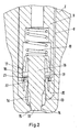
- eine Detailansicht einer Kammeranordnung der Abgabevorrichtung für ein Fluid mit dem Ventilelement im geschlossenen Zustand,
- Fig. 3
- eine Abgabevorrichtung für ein Fluid mit dem Ventilelement in einem geöffneten Zustand,
- Fig. 4
- eine Detailansicht der Kammeranordnung der Abgabevorrichtung für ein Fluid mit dem Ventilelement in einem geöffneten Zustand.
-
Fig. 1 zeigt eine Abgabevorrichtung 1 für ein Fluid. Die Abgabevorrichtung 1 weist ein Kopfbasisteil 2 auf, das auf einem Snap-On 3 angeordnet ist. Ein Kegel 4 erstreckt sich vom Kopfbasisteil 2 in eine Axialrichtung durch den Snap-On 3 in ein Gehäuse 5. Der Kegel 4 wirkt im Gehäuse 5 mit einer Gehäusefeder 6 zusammen. Der Kegel 4 weist einen Fluidkanal 7 auf. Der Fluidkanal 7 erstreckt sich in der Axialrichtung in Richtung auf das Kopfbasisteil 2. - Der Fluidkanal 7 setzt sich im Kopfbasisteil 2 in einen Linerkanal 8 fort. Dieser Linerkanal 8 ist zwischen dem Kopfbasisteil 2 und einem Liner 9 angeordnet.
- Der Linerkanal 8 mündet in eine Kammeranordnung 10. Diese Kammeranordnung 10 weist eine Ventilkammer 11 auf. Ein Raum 12 lässt dabei einen Flüssigkeitspfad von der Ventilkammer 11 zu einer Düsenkammer 13 frei. Die Düsenkammer 13 weist eine Abgabeöffnung 14 auf. Die Abgabeöffnung 14 ist in Form einer Kalotte 15 ausgebildet.
- In der Kammeranordnung 10 ist ein Ventilelement 16 angeordnet. Dieses weist in der Ventilkammer 11 eine erste Dichtlippe 17 auf. An einem der ersten Dichtlippe 17 gegenüberliegenden Ende des Ventilelements 16, ist das Ventilelement 16 in Form eines Zylinders 18 ausgebildet. Die Ventilkammer 11 wird durch die erste Dichtlippe 17 in zwei Bereiche unterteilt. Der Flüssigkeitspfad des Linerkanals 8 setzt sich in einen ersten Bereich der Ventilkammer 11 fort. Dieser erste Bereich der Ventilkammer 11 ist mittels der ersten Dichtlippe 17 von einem zweiten Bereich der Ventilkammer 11 räumlich getrennt. Der zweite Bereich der Ventilkammer 11 weist eine Kopffeder 19 auf.
- Zwischen Ventilkammer 11 und Düsenkammer 13 ist ein Ventilsitz 20 angeordnet. Dieser Ventilsitz 20 weist mindestens eine Krone 21 auf. Die Krone 21 ist am Übergang vom Linerkanal 8 zur Ventilkammer 11 angeordnet. Weiterhin weist der Ventilsitz 20 ein Dichtelement 22 auf.
- Die soeben beschriebene Ausführungsform der Abgabevorrichtung 1 ist in den
Fig. 1 bis 4 dargestellt. Identische Merkmale sind dabei mit identischen Bezugszeichen versehen.Fig. 1 stellt dabei einen Zustand der Abgabevorrichtung 1 dar, in dem das Ventilelement 16 in einem geschlossenen Zustand angeordnet ist.Fig. 3 hingegen zeigt dieselbe Abgabevorrichtung 1, in der das Ventilelement 16 in einem geöffneten Zustand angeordnet ist. - Eine Funktionsweise der Abgabevorrichtung 1 soll nun anhand der
Fig. 2 und4 näher erläutert werden. - Zur Abgabe des Fluides bewegt ein Anwender das Kopfbasisteil 2 in der Axialrichtung auf den Snap-On 3 zu. Hierdurch wird der Kegel 4 im inneren des Gehäuses 5 entgegen der Federkraft der Gehäusefeder 6 bewegt. Dabei verringert sich das Volumen in einer Pumpkammer des Gehäuses 5. Die Pumpkammer wird durch den die Gehäusefeder 6 umgebenden Raum gebildet. Durch einen Hub des Kegels 4 innerhalb der Pumpkammer wird die geförderte Fluidmenge bestimmt. Hierdurch wird die Dosierung einer vorbestimmten Fluidmenge ermöglicht. Durch den entstehenden Überdruck wird das Fluid aus der Pumpkammer in den Fluidkanal 7 verdrängt. Das Fluid wird in einer Axialrichtung entlang des Fluidkanals 7 transportiert. Der Transport des Fluides setzt sich im Liner 9 durch den Linerkanal 8 fort. An einem axialen Ende des Linerkanals 8 passiert das Fluid schließlich die Krone 21 und gelangt in die Ventilkammer 11.
- Es kommt zu einer gewissen Fluidansammlung in der Ventilkammer 11. Je mehr Fluid sich in der Ventilkammer 11 ansammelt, desto größer wird der Druck des Fluides auf das Ventilelement 16. Die Ventilkammer 11 ist dabei mittels der ersten Dichtlippe 17 gegenüber dem Bereich der Ventilkammer 11 abgedichtet, in dem die Kopffeder 19 angeordnet ist. Weiterhin ist die Ventilkammer 11 mittels des Dichtelements 22 gegenüber der Düsenkammer 13 abgedichtet. Das sich in der Ventilkammer 11 sammelnde Fluid verdrängt somit das Ventilelement 16 entgegen der Federkraft der Kopffeder 19.
- Bevor die Verdrängung des Ventilelements 16 entgegen der Federkraft der Kopffeder 19 stattfindet, dichtet der Zylinder 18 die Abgabeöffnung 14 ab. Diese Abdichtung wird beispielsweise über einen Formschluss erreicht. Die Möglichkeit einer Kontamination der Düsenkammer 13 kann vermieden werden.
- Das in die Ventilkammer 11 eintretende Fluid verdrängt nun das Ventilelement 16 entgegen der Federkraft der Kopffeder 19. Hieraus resultiert ein Hub des Ventilelements 16. Nach einem zweiten Hub des Ventilelements 16 gibt der Zylinder 18 die Abgabeöffnung 14 frei. Zu diesem Zeitpunkt liegt das Dichtelement 22 jedoch noch fluiddicht am Ventilelement 16 an. Das in der Ventilkammer 11 befindliche Fluid kann nicht in den Raum 12 eintreten. Der Raum12 ist hier als Nut in dem Ventilelement 16 ausgebildet. Der Hub des Ventilelements 16 setzt sich fort, bis das Dichtelement 22 den Raum 12 erreicht. Das Ventilelement 16 hat nunmehr einen ersten Hub zurückgelegt. Während dieses ersten Hubs dichtet das Dichtelement 22 gegenüber dem Ventilelement 16 ab.
- Sobald der Hub des Ventilelements 16 den ersten vorbestimmten Hub überschreitet, kommt es zu einer Überlappung des Dichtelements 22 mit dem Raum 12. Das Dichtelement 22 gibt nunmehr einen Flüssigkeitspfad in den Raum 12 frei. Das in der Ventilkammer 11 befindliche Fluid kann in den Raum 12 eintreten. Das Fluid wird durch den Raum 12 in die Düsenkammer 13 transportiert. Im gezeigten Ausführungsbeispiel ist der erste Hub als ein Vielfaches des zweiten Hubs ausgebildet. Hierdurch wird erreicht, dass der Zylinder 18 nach einem Hub, der größer als der erste Hub ist, die Abgabeöffnung 14 vollständig freigegeben hat.
- Das Volumen der Ventilkammer 11 ist größer als das Volumen des Raums 12. Hierdurch wird das Fluid bei Eintritt in den Raum 12 beschleunigt. Diese Beschleunigung ist unerwünscht, da eine kontrollierte tropfenförmige Abgabe des Fluides gewollt ist. Aus diesem Grunde weist die Düsenkammer 13 ein größeres Volumen als der Raum 12 auf. Auch ist die Düsenkammer 13 in der Transportrichtung des Fluides nach dem Raum 12 angeordnet. Das in dem Raum 12 beschleunigte Fluid kann somit in der Düsenkammer 13 expandieren. Hierdurch wird das Fluid abgebremst. Die Düsenkammer 13 weist dann die Abgabeöffnung 14 auf. Das Fluid kann aus der Abgabeöffnung 14 entlang der Kalotte 15 tropfenförmig austreten.
- Zum einen wird hierdurch die tropfenförmige Abgabe des Fluides durch die Abgabevorrichtung 1 ermöglicht. Zum anderen kann eine Kontamination der Abgabevorrichtung 1 mit Fremdstoffen weitgehend vermieden werden.
- Die Kontamination der Abgabevorrichtung 1 wird einerseits durch die Abdichtung der Abgabeöffnung 14 mittels des Zylinders 18 in einem geschlossenen Zustand des Ventilelements 16 erreicht. Weiterhin dient die räumliche Trennung von Düsenkammer 13 und Ventilkammer 11 durch den Ventilsitz 20 diesem Zweck. Das Dichtelement 22 verhindert bei einem Hub, der geringer als der erste Hub ist, ein Eindringen von Fremdstoffen von der Düsenkammer 13 in die Ventilkammer 11. Bei einem Hub, der größer ist als der erste Hub, gibt das Dichtelement 22 den Flüssigkeitspfad frei. Fluid aus der Ventilkammer 11 tritt sodann in den Raum 12 und anschließend in die Düsenkammer 13 ein. Möglicherweise in der Düsenkammer 13 befindliche Fremdstoffe werden somit ausgewaschen. Sie können nicht entgegen der Fluidströmung durch den Raum 12 in die Ventilkammer 11 gelangen. Eine Kontamination der Abgabevorrichtung 1 kann somit weitgehend vermieden werden.
Claims (8)
- Abgabevorrichtung (1) für ein Fluid mit einem Fluidkanal (7) und einer Kammeranordnung (10), in der ein Ventilelement (16) bewegbar angeordnet ist, das mit einer Abgabeöffnung (14) zusammenwirkt, wobei die Kammeranordnung (10) mindestens ein Dichtelement (22) aufweist, das über einen ersten vorbestimmten Hub des Ventilelements (16) gegenüber dem Ventilelement (16) abdichtet, und wobei das Dichtelement (22) über den ersten Hub einen Flüssigkeitspfad von der Kammeranordnung (10) zu der Abgabeöffnung (14) verschließt, dadurch gekennzeichnet, dass das Ventilelement (16) über einen zweiten vorbestimmten Hub des Ventilelements (16) die Abgabeöffnung (14) abdichtet, wobei das Dichtelement (22) über den zweiten Hub den Flüssigkeitspfad von der Kammeranordnung (10) zu der Abgabeöffnung (14) verschließt, wobei das Ventilelement (16) einen Zylinder (18) umfasst, der die Abgabeöffnung (14) durch einen Formschluss abdichtet.
- Abgabevorrichtung nach Anspruch 1, dadurch gekennzeichnet, dass das Dichtelement (22) bei einem Hub des Ventilelements (16), der größer als der erste Hub ist, den Flüssigkeitspfad freigibt.
- Abgabevorrichtung nach einem der Ansprüche 1 oder 2, dadurch gekennzeichnet, dass das Ventilelement (16) einen Raum (12), insbesondere mindestens eine Nut, aufweist, der einen Teil des Flüssigkeitspfades bildet.
- Abgabevorrichtung nach einem der Ansprüche 1 bis 3, dadurch gekennzeichnet, dass die Kammeranordnung (10) eine Ventilkammer (11) und eine Düsenkammer (13) aufweist, wobei das Dichtelement (22) die Düsenkammer (13) gegenüber der Ventilkammer (11) abdichtet.
- Abgabevorrichtung nach Anspruch 4, dadurch gekennzeichnet, dass zwischen Ventilkammer (11) und Düsenkammer (13) ein Ventilsitz (20) angeordnet ist, in dem das Ventilelement (16) bewegbar angeordnet ist, und der das Dichtelement (22) aufweist.
- Abgabevorrichtung nach einem der Ansprüche 4 oder 5, dadurch gekennzeichnet, dass der Flüssigkeitspfad in die Düsenkammer (13) mündet, wobei die Düsenkammer (13) die Abgabeöffnung (14) aufweist.
- Abgabevorrichtung nach einem der Ansprüche 1 bis 6, dadurch gekennzeichnet, dass das Dichtelement (22) als mindestens eine Dichtlippe ausgebildet ist, und über den ersten Hub an dem Ventilelement (16) anliegt.
- Abgabevorrichtung nach Anspruch 1, dadurch gekennzeichnet, dass der erste Hub ein Vielfaches des zweiten Hubs bildet.
Applications Claiming Priority (1)
| Application Number | Priority Date | Filing Date | Title |
|---|---|---|---|
| DE102015104646.6A DE102015104646B3 (de) | 2015-03-26 | 2015-03-26 | Abgabevorrichtung für ein Fluid |
Publications (2)
| Publication Number | Publication Date |
|---|---|
| EP3072597A1 EP3072597A1 (de) | 2016-09-28 |
| EP3072597B1 true EP3072597B1 (de) | 2020-04-15 |
Family
ID=55272238
Family Applications (1)
| Application Number | Title | Priority Date | Filing Date |
|---|---|---|---|
| EP16152682.7A Active EP3072597B1 (de) | 2015-03-26 | 2016-01-26 | Abgabevorrichtung für ein fluid |
Country Status (4)
| Country | Link |
|---|---|
| US (1) | US10155243B2 (de) |
| EP (1) | EP3072597B1 (de) |
| DE (1) | DE102015104646B3 (de) |
| ES (1) | ES2790773T3 (de) |
Cited By (1)
| Publication number | Priority date | Publication date | Assignee | Title |
|---|---|---|---|---|
| WO2023180401A1 (de) * | 2022-03-22 | 2023-09-28 | Matanic Frank | Vorrichtung zum portionierten austragen eines flüssigen mediums |
Families Citing this family (11)
| Publication number | Priority date | Publication date | Assignee | Title |
|---|---|---|---|---|
| US9421199B2 (en) | 2014-06-24 | 2016-08-23 | Sydnexis, Inc. | Ophthalmic composition |
| WO2016172712A2 (en) | 2015-04-23 | 2016-10-27 | Sydnexis, Inc. | Ophthalmic composition |
| EP3302426A4 (de) | 2015-05-29 | 2018-12-05 | Sydnexis, Inc. | D2o-stabilisierte pharmazeutische formulierungen |
| MX2020005217A (es) | 2017-11-21 | 2020-11-24 | Sydnexis Inc | Composicion oftalmica y dispositivo de administracion de la misma. |
| CH716306A2 (de) * | 2019-06-11 | 2020-12-15 | Elc Ceratec Gmbh | Vorrichtung zur dosierten Abgabe einer Flüssigkeit aus einem Behälter und Sprühapplikator mit einer solchen Vorrichtung. |
| EP4164625A1 (de) | 2020-06-10 | 2023-04-19 | Ocular Science, Inc. | Zusammensetzungen und verwendungen in verfahren zur postoperativen augenpflege |
| US20230120997A1 (en) | 2021-10-18 | 2023-04-20 | Ocular Science, Inc. | Compositions and methods for myopia control and orthokeratology lenses treatment |
| DE102023109238A1 (de) | 2023-04-12 | 2024-10-17 | Frank Matanic | Von Hand betätigbare Vorrichtung zum portionierten Austragen einer Flüssigkeit |
| EP4484016A1 (de) | 2023-06-30 | 2025-01-01 | Aero Pump GmbH | Adapter, fluidabgabevorrichtung hiermit und montageverfahren |
| EP4497511B1 (de) | 2023-07-27 | 2026-02-11 | Aero Pump GmbH | Abgabevorrichtung für ein fluid |
| EP4497508A1 (de) | 2023-07-27 | 2025-01-29 | Aero Pump GmbH | Abgabevorrichtung für ein fluid |
Family Cites Families (14)
| Publication number | Priority date | Publication date | Assignee | Title |
|---|---|---|---|---|
| US4182496A (en) * | 1977-12-16 | 1980-01-08 | Ethyl Products Company | Actuator button for fluid dispenser |
| EP0688608A1 (de) * | 1994-03-25 | 1995-12-27 | GUALA S.p.A. | Sprühvorrichtung für handbetätigte Pumpen |
| IT1270138B (it) * | 1994-05-25 | 1997-04-29 | Giovanni Albini | Erogatore di fluidi in pressione nebulizzati , provvisto do otturatore mobile per azione del fluido in pressione |
| IT1272904B (it) * | 1995-01-16 | 1997-07-01 | Elettro Plastica Spa | Pompetta per l'erogazione di liquidi nebulizzati |
| US5842616A (en) * | 1996-04-24 | 1998-12-01 | Ter S.R.L. | Atomized liquid dispenser applicable to manually operated pumps |
| DE19627228A1 (de) * | 1996-07-05 | 1998-01-08 | Pfeiffer Erich Gmbh & Co Kg | Austragvorrichtung für Medien |
| IT1294275B1 (it) * | 1997-07-24 | 1999-03-24 | Giovanni Albini | Pulsante per l'erogazione di fluidi attraverso un ugello mobile sul pulsante stesso |
| DE19807922A1 (de) * | 1998-02-25 | 1999-08-26 | Pfeiffer Erich Gmbh & Co Kg | Spender für Medien |
| DE19840721A1 (de) * | 1998-09-07 | 2000-03-09 | Pfeiffer Erich Gmbh & Co Kg | Spender für Medien |
| US20070221686A1 (en) * | 2006-03-27 | 2007-09-27 | Taesung Industrial Co., Ltd. | Liquid pump dispenser |
| CN2937092Y (zh) * | 2006-08-02 | 2007-08-22 | 袁建军 | 一种新型液体分配器 |
| DE102008027146B4 (de) * | 2008-06-02 | 2012-01-19 | Ing. Erich Pfeiffer Gmbh | Austragvorrichtung |
| CN102421684A (zh) * | 2009-03-19 | 2012-04-18 | 卢姆森股份公司 | 用于流体物质的分配装置 |
| DE102009037164B3 (de) * | 2009-08-03 | 2010-12-09 | Ing. Erich Pfeiffer Gmbh | Austragvorrichtung für flüssige Medien |
-
2015
- 2015-03-26 DE DE102015104646.6A patent/DE102015104646B3/de active Active
-
2016
- 2016-01-26 ES ES16152682T patent/ES2790773T3/es active Active
- 2016-01-26 EP EP16152682.7A patent/EP3072597B1/de active Active
- 2016-03-25 US US15/081,063 patent/US10155243B2/en active Active
Non-Patent Citations (1)
| Title |
|---|
| None * |
Cited By (1)
| Publication number | Priority date | Publication date | Assignee | Title |
|---|---|---|---|---|
| WO2023180401A1 (de) * | 2022-03-22 | 2023-09-28 | Matanic Frank | Vorrichtung zum portionierten austragen eines flüssigen mediums |
Also Published As
| Publication number | Publication date |
|---|---|
| US10155243B2 (en) | 2018-12-18 |
| ES2790773T3 (es) | 2020-10-29 |
| DE102015104646B3 (de) | 2016-06-30 |
| US20160279663A1 (en) | 2016-09-29 |
| EP3072597A1 (de) | 2016-09-28 |
Similar Documents
| Publication | Publication Date | Title |
|---|---|---|
| DE102015104646B3 (de) | Abgabevorrichtung für ein Fluid | |
| EP3576825B1 (de) | Austragvorrichtung für ein flüssiges medium | |
| DE69803361T2 (de) | Vorrichtung zur abgabe vom fliessfähigen produkt mit verschlussvorrichtung | |
| EP0473892B1 (de) | Fluid-Abgabeeinrichtung für keimfreies Fluid | |
| DE69631173T2 (de) | Pumpe mit einen Deckel tragendem Verschlussstopfen | |
| DE69919321T2 (de) | Zerstäubungskopf für einen spender für medien | |
| EP2236213B1 (de) | Austragvorrichtung | |
| EP0550503B1 (de) | Einweg-druckbehälter, insbesondere als nachfüllbehälter für kälte- und klimaanlagen | |
| CH634237A5 (de) | Zerstaeuber, der sowohl in aufrechtem als auch umgedrehtem zustand verwendbar ist. | |
| EP2734371B3 (de) | Druckkopf für einen tintenstrahldrucker | |
| DE2531919B2 (de) | Betätigungsvorrichtung für ein Aerosolventil | |
| EP0361132A2 (de) | Automatische Sprühdose | |
| DE69714025T2 (de) | Verteilungseinrichtung einer einmaligen dosis eines flüssigen produktes | |
| EP1817114B1 (de) | Dosiervorrichtung für wenigstens ein medium | |
| DE60208925T2 (de) | Abgabevorrichtung für medien | |
| EP0887112A2 (de) | Spender für Medien | |
| EP2428485B1 (de) | Zapfventil | |
| EP4497511B1 (de) | Abgabevorrichtung für ein fluid | |
| EP3485236B1 (de) | Pumpkopf sowie dosiervorrichtung | |
| EP4401889B1 (de) | Vorrichtung zum portionierten austragen eines flüssigen mediums | |
| DE60301572T2 (de) | Abgabepumpe für medien | |
| WO2011006547A1 (de) | Druckgasbetriebenes instrument, insbesondere chirurgisches instrument | |
| DE69210322T2 (de) | Wegwerfventil mit Bauteilen zur Verhinderung des Nachfüllens von Druckgasflaschen | |
| EP2762238B1 (de) | Manuelles Pumpsystem für einen Inhalator | |
| EP4345306B1 (de) | Pumpenvorrichtung |
Legal Events
| Date | Code | Title | Description |
|---|---|---|---|
| PUAI | Public reference made under article 153(3) epc to a published international application that has entered the european phase |
Free format text: ORIGINAL CODE: 0009012 |
|
| AK | Designated contracting states |
Kind code of ref document: A1 Designated state(s): AL AT BE BG CH CY CZ DE DK EE ES FI FR GB GR HR HU IE IS IT LI LT LU LV MC MK MT NL NO PL PT RO RS SE SI SK SM TR |
|
| AX | Request for extension of the european patent |
Extension state: BA ME |
|
| STAA | Information on the status of an ep patent application or granted ep patent |
Free format text: STATUS: REQUEST FOR EXAMINATION WAS MADE |
|
| 17P | Request for examination filed |
Effective date: 20170216 |
|
| RBV | Designated contracting states (corrected) |
Designated state(s): AL AT BE BG CH CY CZ DE DK EE ES FI FR GB GR HR HU IE IS IT LI LT LU LV MC MK MT NL NO PL PT RO RS SE SI SK SM TR |
|
| STAA | Information on the status of an ep patent application or granted ep patent |
Free format text: STATUS: EXAMINATION IS IN PROGRESS |
|
| 17Q | First examination report despatched |
Effective date: 20180129 |
|
| GRAP | Despatch of communication of intention to grant a patent |
Free format text: ORIGINAL CODE: EPIDOSNIGR1 |
|
| STAA | Information on the status of an ep patent application or granted ep patent |
Free format text: STATUS: GRANT OF PATENT IS INTENDED |
|
| INTG | Intention to grant announced |
Effective date: 20191204 |
|
| GRAS | Grant fee paid |
Free format text: ORIGINAL CODE: EPIDOSNIGR3 |
|
| GRAA | (expected) grant |
Free format text: ORIGINAL CODE: 0009210 |
|
| STAA | Information on the status of an ep patent application or granted ep patent |
Free format text: STATUS: THE PATENT HAS BEEN GRANTED |
|
| AK | Designated contracting states |
Kind code of ref document: B1 Designated state(s): AL AT BE BG CH CY CZ DE DK EE ES FI FR GB GR HR HU IE IS IT LI LT LU LV MC MK MT NL NO PL PT RO RS SE SI SK SM TR |
|
| REG | Reference to a national code |
Ref country code: CH Ref legal event code: EP |
|
| REG | Reference to a national code |
Ref country code: DE Ref legal event code: R096 Ref document number: 502016009513 Country of ref document: DE |
|
| REG | Reference to a national code |
Ref country code: IE Ref legal event code: FG4D Free format text: LANGUAGE OF EP DOCUMENT: GERMAN |
|
| REG | Reference to a national code |
Ref country code: AT Ref legal event code: REF Ref document number: 1256633 Country of ref document: AT Kind code of ref document: T Effective date: 20200515 |
|
| REG | Reference to a national code |
Ref country code: CH Ref legal event code: NV Representative=s name: VALIPAT S.A. C/O BOVARD SA NEUCHATEL, CH |
|
| REG | Reference to a national code |
Ref country code: NL Ref legal event code: MP Effective date: 20200415 |
|
| REG | Reference to a national code |
Ref country code: LT Ref legal event code: MG4D |
|
| REG | Reference to a national code |
Ref country code: ES Ref legal event code: FG2A Ref document number: 2790773 Country of ref document: ES Kind code of ref document: T3 Effective date: 20201029 |
|
| PG25 | Lapsed in a contracting state [announced via postgrant information from national office to epo] |
Ref country code: IS Free format text: LAPSE BECAUSE OF FAILURE TO SUBMIT A TRANSLATION OF THE DESCRIPTION OR TO PAY THE FEE WITHIN THE PRESCRIBED TIME-LIMIT Effective date: 20200815 Ref country code: SE Free format text: LAPSE BECAUSE OF FAILURE TO SUBMIT A TRANSLATION OF THE DESCRIPTION OR TO PAY THE FEE WITHIN THE PRESCRIBED TIME-LIMIT Effective date: 20200415 Ref country code: NL Free format text: LAPSE BECAUSE OF FAILURE TO SUBMIT A TRANSLATION OF THE DESCRIPTION OR TO PAY THE FEE WITHIN THE PRESCRIBED TIME-LIMIT Effective date: 20200415 Ref country code: PT Free format text: LAPSE BECAUSE OF FAILURE TO SUBMIT A TRANSLATION OF THE DESCRIPTION OR TO PAY THE FEE WITHIN THE PRESCRIBED TIME-LIMIT Effective date: 20200817 Ref country code: FI Free format text: LAPSE BECAUSE OF FAILURE TO SUBMIT A TRANSLATION OF THE DESCRIPTION OR TO PAY THE FEE WITHIN THE PRESCRIBED TIME-LIMIT Effective date: 20200415 Ref country code: LT Free format text: LAPSE BECAUSE OF FAILURE TO SUBMIT A TRANSLATION OF THE DESCRIPTION OR TO PAY THE FEE WITHIN THE PRESCRIBED TIME-LIMIT Effective date: 20200415 Ref country code: GR Free format text: LAPSE BECAUSE OF FAILURE TO SUBMIT A TRANSLATION OF THE DESCRIPTION OR TO PAY THE FEE WITHIN THE PRESCRIBED TIME-LIMIT Effective date: 20200716 Ref country code: NO Free format text: LAPSE BECAUSE OF FAILURE TO SUBMIT A TRANSLATION OF THE DESCRIPTION OR TO PAY THE FEE WITHIN THE PRESCRIBED TIME-LIMIT Effective date: 20200715 |
|
| PG25 | Lapsed in a contracting state [announced via postgrant information from national office to epo] |
Ref country code: LV Free format text: LAPSE BECAUSE OF FAILURE TO SUBMIT A TRANSLATION OF THE DESCRIPTION OR TO PAY THE FEE WITHIN THE PRESCRIBED TIME-LIMIT Effective date: 20200415 Ref country code: BG Free format text: LAPSE BECAUSE OF FAILURE TO SUBMIT A TRANSLATION OF THE DESCRIPTION OR TO PAY THE FEE WITHIN THE PRESCRIBED TIME-LIMIT Effective date: 20200715 Ref country code: RS Free format text: LAPSE BECAUSE OF FAILURE TO SUBMIT A TRANSLATION OF THE DESCRIPTION OR TO PAY THE FEE WITHIN THE PRESCRIBED TIME-LIMIT Effective date: 20200415 Ref country code: HR Free format text: LAPSE BECAUSE OF FAILURE TO SUBMIT A TRANSLATION OF THE DESCRIPTION OR TO PAY THE FEE WITHIN THE PRESCRIBED TIME-LIMIT Effective date: 20200415 |
|
| PG25 | Lapsed in a contracting state [announced via postgrant information from national office to epo] |
Ref country code: AL Free format text: LAPSE BECAUSE OF FAILURE TO SUBMIT A TRANSLATION OF THE DESCRIPTION OR TO PAY THE FEE WITHIN THE PRESCRIBED TIME-LIMIT Effective date: 20200415 |
|
| REG | Reference to a national code |
Ref country code: DE Ref legal event code: R097 Ref document number: 502016009513 Country of ref document: DE |
|
| PG25 | Lapsed in a contracting state [announced via postgrant information from national office to epo] |
Ref country code: SM Free format text: LAPSE BECAUSE OF FAILURE TO SUBMIT A TRANSLATION OF THE DESCRIPTION OR TO PAY THE FEE WITHIN THE PRESCRIBED TIME-LIMIT Effective date: 20200415 Ref country code: EE Free format text: LAPSE BECAUSE OF FAILURE TO SUBMIT A TRANSLATION OF THE DESCRIPTION OR TO PAY THE FEE WITHIN THE PRESCRIBED TIME-LIMIT Effective date: 20200415 Ref country code: DK Free format text: LAPSE BECAUSE OF FAILURE TO SUBMIT A TRANSLATION OF THE DESCRIPTION OR TO PAY THE FEE WITHIN THE PRESCRIBED TIME-LIMIT Effective date: 20200415 Ref country code: RO Free format text: LAPSE BECAUSE OF FAILURE TO SUBMIT A TRANSLATION OF THE DESCRIPTION OR TO PAY THE FEE WITHIN THE PRESCRIBED TIME-LIMIT Effective date: 20200415 Ref country code: CZ Free format text: LAPSE BECAUSE OF FAILURE TO SUBMIT A TRANSLATION OF THE DESCRIPTION OR TO PAY THE FEE WITHIN THE PRESCRIBED TIME-LIMIT Effective date: 20200415 |
|
| PLBE | No opposition filed within time limit |
Free format text: ORIGINAL CODE: 0009261 |
|
| STAA | Information on the status of an ep patent application or granted ep patent |
Free format text: STATUS: NO OPPOSITION FILED WITHIN TIME LIMIT |
|
| PG25 | Lapsed in a contracting state [announced via postgrant information from national office to epo] |
Ref country code: PL Free format text: LAPSE BECAUSE OF FAILURE TO SUBMIT A TRANSLATION OF THE DESCRIPTION OR TO PAY THE FEE WITHIN THE PRESCRIBED TIME-LIMIT Effective date: 20200415 Ref country code: SK Free format text: LAPSE BECAUSE OF FAILURE TO SUBMIT A TRANSLATION OF THE DESCRIPTION OR TO PAY THE FEE WITHIN THE PRESCRIBED TIME-LIMIT Effective date: 20200415 |
|
| 26N | No opposition filed |
Effective date: 20210118 |
|
| PG25 | Lapsed in a contracting state [announced via postgrant information from national office to epo] |
Ref country code: SI Free format text: LAPSE BECAUSE OF FAILURE TO SUBMIT A TRANSLATION OF THE DESCRIPTION OR TO PAY THE FEE WITHIN THE PRESCRIBED TIME-LIMIT Effective date: 20200415 |
|
| PG25 | Lapsed in a contracting state [announced via postgrant information from national office to epo] |
Ref country code: MC Free format text: LAPSE BECAUSE OF FAILURE TO SUBMIT A TRANSLATION OF THE DESCRIPTION OR TO PAY THE FEE WITHIN THE PRESCRIBED TIME-LIMIT Effective date: 20200415 |
|
| PG25 | Lapsed in a contracting state [announced via postgrant information from national office to epo] |
Ref country code: LU Free format text: LAPSE BECAUSE OF NON-PAYMENT OF DUE FEES Effective date: 20210126 |
|
| REG | Reference to a national code |
Ref country code: BE Ref legal event code: MM Effective date: 20210131 |
|
| PG25 | Lapsed in a contracting state [announced via postgrant information from national office to epo] |
Ref country code: IE Free format text: LAPSE BECAUSE OF NON-PAYMENT OF DUE FEES Effective date: 20210126 |
|
| REG | Reference to a national code |
Ref country code: AT Ref legal event code: MM01 Ref document number: 1256633 Country of ref document: AT Kind code of ref document: T Effective date: 20210126 |
|
| PG25 | Lapsed in a contracting state [announced via postgrant information from national office to epo] |
Ref country code: AT Free format text: LAPSE BECAUSE OF NON-PAYMENT OF DUE FEES Effective date: 20210126 |
|
| PG25 | Lapsed in a contracting state [announced via postgrant information from national office to epo] |
Ref country code: BE Free format text: LAPSE BECAUSE OF NON-PAYMENT OF DUE FEES Effective date: 20210131 |
|
| PG25 | Lapsed in a contracting state [announced via postgrant information from national office to epo] |
Ref country code: HU Free format text: LAPSE BECAUSE OF FAILURE TO SUBMIT A TRANSLATION OF THE DESCRIPTION OR TO PAY THE FEE WITHIN THE PRESCRIBED TIME-LIMIT; INVALID AB INITIO Effective date: 20160126 |
|
| PG25 | Lapsed in a contracting state [announced via postgrant information from national office to epo] |
Ref country code: CY Free format text: LAPSE BECAUSE OF FAILURE TO SUBMIT A TRANSLATION OF THE DESCRIPTION OR TO PAY THE FEE WITHIN THE PRESCRIBED TIME-LIMIT Effective date: 20200415 |
|
| P01 | Opt-out of the competence of the unified patent court (upc) registered |
Effective date: 20230530 |
|
| PG25 | Lapsed in a contracting state [announced via postgrant information from national office to epo] |
Ref country code: MK Free format text: LAPSE BECAUSE OF FAILURE TO SUBMIT A TRANSLATION OF THE DESCRIPTION OR TO PAY THE FEE WITHIN THE PRESCRIBED TIME-LIMIT Effective date: 20200415 |
|
| PG25 | Lapsed in a contracting state [announced via postgrant information from national office to epo] |
Ref country code: MT Free format text: LAPSE BECAUSE OF FAILURE TO SUBMIT A TRANSLATION OF THE DESCRIPTION OR TO PAY THE FEE WITHIN THE PRESCRIBED TIME-LIMIT Effective date: 20200415 |
|
| PG25 | Lapsed in a contracting state [announced via postgrant information from national office to epo] |
Ref country code: TR Free format text: LAPSE BECAUSE OF FAILURE TO SUBMIT A TRANSLATION OF THE DESCRIPTION OR TO PAY THE FEE WITHIN THE PRESCRIBED TIME-LIMIT Effective date: 20200415 |
|
| REG | Reference to a national code |
Ref country code: CH Ref legal event code: U11 Free format text: ST27 STATUS EVENT CODE: U-0-0-U10-U11 (AS PROVIDED BY THE NATIONAL OFFICE) Effective date: 20260201 |
|
| PGFP | Annual fee paid to national office [announced via postgrant information from national office to epo] |
Ref country code: GB Payment date: 20260122 Year of fee payment: 11 |
|
| PGFP | Annual fee paid to national office [announced via postgrant information from national office to epo] |
Ref country code: ES Payment date: 20260217 Year of fee payment: 11 |
|
| PGFP | Annual fee paid to national office [announced via postgrant information from national office to epo] |
Ref country code: DE Payment date: 20260126 Year of fee payment: 11 |
|
| PGFP | Annual fee paid to national office [announced via postgrant information from national office to epo] |
Ref country code: IT Payment date: 20260130 Year of fee payment: 11 |
|
| PGFP | Annual fee paid to national office [announced via postgrant information from national office to epo] |
Ref country code: FR Payment date: 20260121 Year of fee payment: 11 |
|
| PGFP | Annual fee paid to national office [announced via postgrant information from national office to epo] |
Ref country code: CH Payment date: 20260201 Year of fee payment: 11 |