EP3071320B1 - Mixing reactor and method - Google Patents
Mixing reactor and method Download PDFInfo
- Publication number
- EP3071320B1 EP3071320B1 EP14820913.3A EP14820913A EP3071320B1 EP 3071320 B1 EP3071320 B1 EP 3071320B1 EP 14820913 A EP14820913 A EP 14820913A EP 3071320 B1 EP3071320 B1 EP 3071320B1
- Authority
- EP
- European Patent Office
- Prior art keywords
- fluid
- mixing reactor
- inlet
- reactor
- passage
- Prior art date
- Legal status (The legal status is an assumption and is not a legal conclusion. Google has not performed a legal analysis and makes no representation as to the accuracy of the status listed.)
- Active
Links
Images

Classifications
-
- B—PERFORMING OPERATIONS; TRANSPORTING
- B01—PHYSICAL OR CHEMICAL PROCESSES OR APPARATUS IN GENERAL
- B01J—CHEMICAL OR PHYSICAL PROCESSES, e.g. CATALYSIS OR COLLOID CHEMISTRY; THEIR RELEVANT APPARATUS
- B01J14/00—Chemical processes in general for reacting liquids with liquids; Apparatus specially adapted therefor
-
- B—PERFORMING OPERATIONS; TRANSPORTING
- B01—PHYSICAL OR CHEMICAL PROCESSES OR APPARATUS IN GENERAL
- B01F—MIXING, e.g. DISSOLVING, EMULSIFYING OR DISPERSING
- B01F25/00—Flow mixers; Mixers for falling materials, e.g. solid particles
- B01F25/30—Injector mixers
- B01F25/31—Injector mixers in conduits or tubes through which the main component flows
- B01F25/314—Injector mixers in conduits or tubes through which the main component flows wherein additional components are introduced at the circumference of the conduit
-
- B—PERFORMING OPERATIONS; TRANSPORTING
- B01—PHYSICAL OR CHEMICAL PROCESSES OR APPARATUS IN GENERAL
- B01F—MIXING, e.g. DISSOLVING, EMULSIFYING OR DISPERSING
- B01F23/00—Mixing according to the phases to be mixed, e.g. dispersing or emulsifying
- B01F23/40—Mixing liquids with liquids; Emulsifying
- B01F23/405—Methods of mixing liquids with liquids
-
- B—PERFORMING OPERATIONS; TRANSPORTING
- B01—PHYSICAL OR CHEMICAL PROCESSES OR APPARATUS IN GENERAL
- B01F—MIXING, e.g. DISSOLVING, EMULSIFYING OR DISPERSING
- B01F35/00—Accessories for mixers; Auxiliary operations or auxiliary devices; Parts or details of general application
- B01F35/50—Mixing receptacles
-
- B—PERFORMING OPERATIONS; TRANSPORTING
- B01—PHYSICAL OR CHEMICAL PROCESSES OR APPARATUS IN GENERAL
- B01F—MIXING, e.g. DISSOLVING, EMULSIFYING OR DISPERSING
- B01F35/00—Accessories for mixers; Auxiliary operations or auxiliary devices; Parts or details of general application
- B01F35/71—Feed mechanisms
-
- B—PERFORMING OPERATIONS; TRANSPORTING
- B01—PHYSICAL OR CHEMICAL PROCESSES OR APPARATUS IN GENERAL
- B01F—MIXING, e.g. DISSOLVING, EMULSIFYING OR DISPERSING
- B01F35/00—Accessories for mixers; Auxiliary operations or auxiliary devices; Parts or details of general application
- B01F35/90—Heating or cooling systems
- B01F35/92—Heating or cooling systems for heating the outside of the receptacle, e.g. heated jackets or burners
-
- B—PERFORMING OPERATIONS; TRANSPORTING
- B01—PHYSICAL OR CHEMICAL PROCESSES OR APPARATUS IN GENERAL
- B01J—CHEMICAL OR PHYSICAL PROCESSES, e.g. CATALYSIS OR COLLOID CHEMISTRY; THEIR RELEVANT APPARATUS
- B01J19/00—Chemical, physical or physico-chemical processes in general; Their relevant apparatus
- B01J19/0046—Sequential or parallel reactions, e.g. for the synthesis of polypeptides or polynucleotides; Apparatus and devices for combinatorial chemistry or for making molecular arrays
-
- B—PERFORMING OPERATIONS; TRANSPORTING
- B01—PHYSICAL OR CHEMICAL PROCESSES OR APPARATUS IN GENERAL
- B01J—CHEMICAL OR PHYSICAL PROCESSES, e.g. CATALYSIS OR COLLOID CHEMISTRY; THEIR RELEVANT APPARATUS
- B01J19/00—Chemical, physical or physico-chemical processes in general; Their relevant apparatus
- B01J19/24—Stationary reactors without moving elements inside
- B01J19/2415—Tubular reactors
- B01J19/242—Tubular reactors in series
-
- B—PERFORMING OPERATIONS; TRANSPORTING
- B01—PHYSICAL OR CHEMICAL PROCESSES OR APPARATUS IN GENERAL
- B01J—CHEMICAL OR PHYSICAL PROCESSES, e.g. CATALYSIS OR COLLOID CHEMISTRY; THEIR RELEVANT APPARATUS
- B01J19/00—Chemical, physical or physico-chemical processes in general; Their relevant apparatus
- B01J19/24—Stationary reactors without moving elements inside
- B01J19/2415—Tubular reactors
- B01J19/244—Concentric tubes
-
- B—PERFORMING OPERATIONS; TRANSPORTING
- B01—PHYSICAL OR CHEMICAL PROCESSES OR APPARATUS IN GENERAL
- B01J—CHEMICAL OR PHYSICAL PROCESSES, e.g. CATALYSIS OR COLLOID CHEMISTRY; THEIR RELEVANT APPARATUS
- B01J3/00—Processes of utilising sub-atmospheric or super-atmospheric pressure to effect chemical or physical change of matter; Apparatus therefor
- B01J3/008—Processes carried out under supercritical conditions
-
- B—PERFORMING OPERATIONS; TRANSPORTING
- B01—PHYSICAL OR CHEMICAL PROCESSES OR APPARATUS IN GENERAL
- B01F—MIXING, e.g. DISSOLVING, EMULSIFYING OR DISPERSING
- B01F25/00—Flow mixers; Mixers for falling materials, e.g. solid particles
- B01F2025/91—Direction of flow or arrangement of feed and discharge openings
- B01F2025/915—Reverse flow, i.e. flow changing substantially 180° in direction
-
- B—PERFORMING OPERATIONS; TRANSPORTING
- B01—PHYSICAL OR CHEMICAL PROCESSES OR APPARATUS IN GENERAL
- B01F—MIXING, e.g. DISSOLVING, EMULSIFYING OR DISPERSING
- B01F2101/00—Mixing characterised by the nature of the mixed materials or by the application field
- B01F2101/2204—Mixing chemical components in generals in order to improve chemical treatment or reactions, independently from the specific application
-
- B—PERFORMING OPERATIONS; TRANSPORTING
- B01—PHYSICAL OR CHEMICAL PROCESSES OR APPARATUS IN GENERAL
- B01J—CHEMICAL OR PHYSICAL PROCESSES, e.g. CATALYSIS OR COLLOID CHEMISTRY; THEIR RELEVANT APPARATUS
- B01J2219/00—Chemical, physical or physico-chemical processes in general; Their relevant apparatus
- B01J2219/00274—Sequential or parallel reactions; Apparatus and devices for combinatorial chemistry or for making arrays; Chemical library technology
- B01J2219/00277—Apparatus
- B01J2219/00495—Means for heating or cooling the reaction vessels
-
- B—PERFORMING OPERATIONS; TRANSPORTING
- B01—PHYSICAL OR CHEMICAL PROCESSES OR APPARATUS IN GENERAL
- B01J—CHEMICAL OR PHYSICAL PROCESSES, e.g. CATALYSIS OR COLLOID CHEMISTRY; THEIR RELEVANT APPARATUS
- B01J2219/00—Chemical, physical or physico-chemical processes in general; Their relevant apparatus
- B01J2219/00274—Sequential or parallel reactions; Apparatus and devices for combinatorial chemistry or for making arrays; Chemical library technology
- B01J2219/00583—Features relative to the processes being carried out
- B01J2219/0059—Sequential processes
-
- B—PERFORMING OPERATIONS; TRANSPORTING
- B01—PHYSICAL OR CHEMICAL PROCESSES OR APPARATUS IN GENERAL
- B01J—CHEMICAL OR PHYSICAL PROCESSES, e.g. CATALYSIS OR COLLOID CHEMISTRY; THEIR RELEVANT APPARATUS
- B01J2219/00—Chemical, physical or physico-chemical processes in general; Their relevant apparatus
- B01J2219/00274—Sequential or parallel reactions; Apparatus and devices for combinatorial chemistry or for making arrays; Chemical library technology
- B01J2219/00583—Features relative to the processes being carried out
- B01J2219/00599—Solution-phase processes
Definitions
- This invention relates to mixing reactors such as may (non-exclusively) be suitable for producing particles such as nanoparticles or Metal-Organic frameworks, a cascade of such reactors and a method of using such reactors to mix fluids, typically but non-exclusively so as to produce such particles.
- Metal and metal oxide particles with nanometre scale dimensions have a wide range of uses, including (but not limited to) catalysts, pigments, polishes, ultraviolet absorbers and in ceramics. It is well known that such particles can be formed by chemical reaction of aqueous solutions of metal salts with heated, pressurised or supercritical water. In principle, this methodology offers distinct advantages over other methods of nanoparticle creation in terms of cost and viability as it allows the reaction to be performed as a continuous process. However, it is difficult to perform this reaction on a commercial scale utilising current methods because existing reactor configurations do not allow the precipitation reaction to be controlled effectively leading to frequent blockage of the reactor and inadequate control of particle size and shape. Hence within this process, the design of the reactor where the water and the salt solution mix is of crucial importance to the size and properties of the nanoparticles produced.
- the PCT patent application published as WO2005/077505 describes a counter-current mixing reactor where supercritical water is introduced into a first inlet and a metal salt solution is introduced at a second inlet, the resultant nanoparticle-bearing suspension being extracted at an outlet.
- the first inlet is positioned within the outlet, so that the mixing occurs where the flow of supercritical water changes direction through 180 degrees.
- DE102006015708 discloses a procedure for supercritical wet-oxidation of oxidizable substances or mixtures including a reactant. Water is fed along a wall of a reaction chamber in which wet oxidation is carried out, in order to heat it to supercritical conditions. The water is led into an upstream whilst the reactant is led into a vertical downstream during the supercritical oxidation reaction.
- US2013/134106 discloses a series of two reaction chambers for carrying out decomposition reactions.
- the outlet of the first reaction chamber is in direct communication with the inlet of the second reaction chamber without narrowing.
- the outer passage is closer to the surface than the inner passage, it can be more easily heated by a heater surrounding the mixing reactor than the inner passage or the fluid flowing into the first inlet.
- a heater to the body will preferentially heat fluid flowing through the outer passage, and is unlikely to substantially heat fluid flowing into the first inlet until after it has passed the junction.
- a metal salt is introduced to the first inlet, there will be no significant heating of the first inlet by a heater attached to the body, but there will be heating of a (typically supercritical) fluid introduced into the second inlet.
- the outer passage enters the inner passage at an angle of 90 degrees to the length, plus or minus 45 degrees.
- the junction may comprise an orifice in the inner wall, with a portion of the outer passage preceding the orifice that is at the angle relative to the length.
- the further outer passage may be a further outer passage that is also closer to the surface than the inner passage, the further outer passage having a further second inlet at the second end, travelling through the body along the length and meeting the inner passage at a further junction at the first end, the further outer passage joining the inner passage through the side wall at the further junction.
- the further outer passage will be symmetrical to the outer passage relative to the inner passage; this allows for symmetrical mixing, which can allow the reactor generate the best products in terms of composition, uniform particle sizes and narrow particle size distribution.
- the outer passage could comprise a sleeve coaxially surrounding the inner passage; this would also provide for symmetrical mixing.
- the surface will exclude the first and second ends.
- the reactor may further comprise a heater coupled to the surface, such as a band heater. This will, as discussed previously, preferentially heat the outer passage rather than the inner passage or the first inlet.
- the body may be made of heat-conductive material, such as a metal material, such as stainless steel, typically stainless steel 316, or alloys such as Hastelloy, Inconel, Monel or Nimonic.
- the reactor may comprise an extension passage, extending out of the body from the outlet. This can allow the fluid flowing out of the reactor to be provided with heating or cooling as desired.
- the extension passage may be provided with heating or cooling apparatus through which it passes.
- the reactor is suitable for mixing two fluids. Typically, it will be suitable for forming particles, such as nanoparticles or metal-organic framework (MOF) particles.
- particles such as nanoparticles or metal-organic framework (MOF) particles.
- a cascade of mixing reactors comprising a first mixing reactor in accordance with the first aspect of the invention and a second mixing reactor in accordance with the first aspect of the invention, in which the outlet of the first mixing reactor is coupled to the first inlet of the second mixing reactor.
- a method of mixing two fluids comprising delivering a first fluid through the first inlet of a mixing reactor in accordance with the first aspect of the invention, delivering a second fluid through the second inlet of the mixing reactor and extracting a mixed fluid from the outlet.
- any or the first, second or mixed fluids can be liquids, including solutions or suspensions.
- the first fluid will comprise a metal salt solution
- the mixed fluid will be a particle-bearing suspension.
- the mixing reactor will mix the fluid and the metal salt solution, so that they mix together and particles form. As discussed above, the mixing will be efficient due to the turbulence induced in the flow by the junction.
- the method may comprise heating the second fluid.
- the heating may occur through the application of heat to the surface of the reactor.
- the application of heat may be through a heater, such as a band heater, applied to the surface of the reactor. Such heating will preferentially heat the second fluid and not the first fluid.
- the method may comprise heating the second fluid to a temperature above that of the first fluid before the second fluid is delivered to the second inlet.
- the reactor may be used with the second end uppermost, so that buoyancy effects also assist with the mixing of the second fluid and the first fluid.
- the second fluid may be water, typically supercritical water or alcohols or other organic solvents.
- the metal salt solution may be, for example, a solution of metal nitrates, metal sulfates, metal acetates, metal acetylacetones, metal halides, or metal carbonates, and more particularly may be any of Iron nitrate, iron acetate, iron sulfate, aluminium nitrate, zinc nitrate, copper nitrate, copper acetate, nickel nitrate, calcium acetate, calcium nitrate, barium nitrate, cobalt acetate, titanium bis(ammonium lactato)dihydroxide, titanium tetrachloride, platinum nitrate, palladium nitrate, cerium nitrate or others.
- the method may comprise heating or cooling the mixed fluid as it passes through the extension tube.
- the method may comprise passing the mixed fluid through a further mixing reactor in accordance with the first aspect of the invention, in which the mixed fluid is introduced to the first inlet of the further mixing reactor, a third fluid is introduced at the second inlet of the further mixing reactor and a further mixed fluid is extracted at the outlet of the further mixing reactor.
- the third fluid may be, for example, a secondary metal salt solution, or a solution containing a "capping agent", including but not limited to organic acids (e.g. citric acid), thiols (e.g. methanethiol) and polymers (e.g. polyvinylpyrrolidone).
- the mixing reactor and the further mixing reactor may form a cascade in accordance with the second aspect of the invention.
- the particles may be nanoparticles, or metal-organic framework (MOF) particles, or other suitable particles that can be formed by combining a metal salt solution with the fluid.
- MOF metal-organic framework
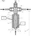
- Figures 1 and 2 show a mixing reactor 1 in accordance with a first aspect of the invention. It comprises a metal body 2 having a first inlet 3 in a first end 12 of the body and two second inlets 5 and an outlet 4 in a second end of the body.
- the body 2 is generally elongate and has a length 15, and an outer surface 14 separating the two ends 12, 13.
- the reactor is used with the second end 13 uppermost (that is as if the accompanying drawings were viewed vertically).
- An inner passage 6 runs from the first inlet 3 to the outlet 4 along the length.
- Two outer passages 7 run from respective second inlets 5 at the second end of the body to a junction 11 at the first end of body, where they each enter the inner passage 6.
- the outer passages 7 lie between the inner passage 6 and the outer surface 14.
- outer passages 7 join the inner passage 6 through respective orifices 16 in the side walls 17 of the inner passage 6.
- outer passage 7a there is a short length of outer passage 7a that is perpendicular to the length 15 and hence the inner passage 6.
- a metal salt solution is introduced into the first inlet 3, and preheated supercritical water (or other suitable fluid such as alcohol) is introduced into the second inlets 5, the supercritical water will pass through outer passages 7 until it reaches the orifices 16. At this point, the supercritical water will be introduced into the stream of metal salt solution that is passing from the first inlet 3 through the inner passage 6. Because of the perpendicular introduction, turbulence will be induced at the junction 11, leading to mixing of the metal salt solution and the supercritical water. The mixing is consistent, symmetrical and thorough, leading to a satisfactory yield of consistent nanoparticles.
- the turbulence and consequent mixing continues as the mixed fluid passes up the inner passage 6 towards the outlet 4, aided by the differences in density and viscosity between the two fluids. There is no need to employ mechanical impellers or the like.
- the nanoparticle-bearing suspension can then be extracted from the outlet 4.
- backflow that is, flow of the metal salt solution into the outer passages
- backflow that is, flow of the metal salt solution into the outer passages
- the flow rate of the supercritical fluid needs to be high enough to avoid backflow
- the size d of the orifices should be small enough to avoid backflow.
- a high flow rate and a small orifice will lead to increased turbulence and so more homogeneous mixing, although too small an orifice will lead to back-pressure issues with pumping the supercritical fluid.
- There are several parameters which may need to be considered when choosing the flow rate including the flow rate of the metal salt solution, the relative diameters of the passages 6, 7, and the lengths of the perpendicular lengths 7a of the outer passages.
- passages 6, 7 are symmetrical about the centreline of the inner passage 6. This means that the mixing is symmetrical, which we have appreciated as being important when generating the best products in terms of composition, uniform particle sizes and narrow particle size distribution. The whole flow can be very quickly and evenly mixed together.
- a band heater 10 around the surface 14. This therefore preferentially heats the outer passages 7 and so their contents, the supercritical water. Because the heater 10 does not extend to the first inlet 3 or across the first end 3, there is no significant heating of the metal salt before reaching the junction 11. Unwanted heating can lead to precipitation of the metal salts out of solution and can effect the formation of nanoparticles, as well as leading to pumping problems. On the other hand, there is little opportunity for the supercritical water to cool having passed through the outer passage adjacent to the heater, and so will be at the correct temperature for the reaction. Any heat loss between the second inlets 5 and the heater 10 can be mitigated by using suitable thermal lagging.
- the present reactor provides little opportunity for particle accumulation and/or lining of internal surfaces of the reactor, which are most likely to occur where the product stream is hot.
- the potential for particle accumulation can be minimised by avoiding narrow constrictions, artefacts such as edges, ridges and corners (on the internal surfaces of the apparatus) and changes in overall flow direction in the region of apparatus between the mixing point (that is, the junction 11) and where the product stream is cooled after the outlet 4.
- the present design allows for a reactor that is completely free of zones which may allow particle accumulation.
- the present reactor can be made substantially seamless and without any loss of symmetry between the junction 11 and the point where the product has been substantially cooled in, for example, a downstream heat exchanger.
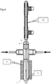
- the angle at which the supercritical water flow is introduced can be varied as shown in the alternative embodiments shown in Figures 3a and 3b of the accompanying drawings.
- the part 7b, 7c of the outer passage leading to the orifices 16 can be angled against the flow from the first inlet as shown in Figure 3a , or with the flow as shown in Figure 3b , as long as a substantial perpendicular element is still maintained.
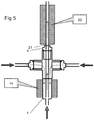
- the mixing reactor 1 can be used in series with various other equipment without deleterious effect on the advantages it provides.
- a heat exchanger 20 is connected around an extension tube 21 extending, typically seamlessly from the outlet 4.
- the nanoparticle-bearing suspension can be cooled without presenting significant opportunity for blockages to form.
- a further heater 22 can be provided around the extension tube 21. Again, there is little opportunity for nanoparticle agglomerations to form.
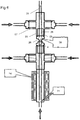
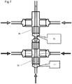
- the mixing reactor 1 of the first embodiment of the invention is employed in series with a second mixing reactor 25.
- the second mixing reactor 25 functions in a similar way to that 1 of the first embodiment, except that it is not provided with a heater 10.
- the outlet 4 of the first mixing reactor 1 is coupled to the first inlet 26 of the second mixing reactor.
- a further fluid for example, a secondary metal salt solution, or a solution containing a "capping agent", including but not limited to organic acids (e.g. citric acid), thiols (e.g. methanethiol) and polymers (e.g. polyvinylpyrrolidone), is introduced to the second inlets 27 of the second mixing reactor.
- the inner 28 and outer 29 passages of the second mixing reactor meet at a junction 30 in the same manner as in the first embodiment, the junction 30 providing a second mixing point.
- the further processed suspension then can be extracted from the second mixing reactor's outlet 31.
- the reactor in both its first embodiment of Figures 1 and 2 and in the multi-stage configuration of Figure 6 need not have a outer surface 14 with a band heater 10; the heated feed can instead be introduced using only cross-pieces and reducers (in this case a cross-piece is favoured significantly over a T-piece in order to achieve symmetrical mixing, as there is little distance for the heated flow to become uniform).
Landscapes
- Chemical & Material Sciences (AREA)
- Chemical Kinetics & Catalysis (AREA)
- Organic Chemistry (AREA)
- Physical Or Chemical Processes And Apparatus (AREA)
Applications Claiming Priority (2)
| Application Number | Priority Date | Filing Date | Title |
|---|---|---|---|
| GBGB1320417.7A GB201320417D0 (en) | 2013-11-19 | 2013-11-19 | Mixing reactors |
| PCT/GB2014/053413 WO2015075439A1 (en) | 2013-11-19 | 2014-11-19 | Mixing reactor and method |
Publications (2)
| Publication Number | Publication Date |
|---|---|
| EP3071320A1 EP3071320A1 (en) | 2016-09-28 |
| EP3071320B1 true EP3071320B1 (en) | 2020-11-18 |
Family
ID=49883857
Family Applications (1)
| Application Number | Title | Priority Date | Filing Date |
|---|---|---|---|
| EP14820913.3A Active EP3071320B1 (en) | 2013-11-19 | 2014-11-19 | Mixing reactor and method |
Country Status (6)
| Country | Link |
|---|---|
| US (1) | US10406499B2 (enExample) |
| EP (1) | EP3071320B1 (enExample) |
| JP (2) | JP2016538995A (enExample) |
| KR (1) | KR102405044B1 (enExample) |
| GB (1) | GB201320417D0 (enExample) |
| WO (1) | WO2015075439A1 (enExample) |
Families Citing this family (10)
| Publication number | Priority date | Publication date | Assignee | Title |
|---|---|---|---|---|
| GB201320417D0 (en) | 2013-11-19 | 2014-01-01 | Univ Nottingham | Mixing reactors |
| KR101930234B1 (ko) * | 2016-10-12 | 2018-12-18 | 최종문 | 유체혼합 토출장치 |
| GB201721808D0 (en) * | 2017-12-22 | 2018-02-07 | Sensient Colors Uk Ltd | Nanaoparticle dispersions |
| GB201811076D0 (en) | 2018-07-05 | 2018-08-22 | Sensient Colors Uk Ltd | Nanoparticle dispersions |
| AU2021200246A1 (en) | 2020-01-31 | 2021-08-19 | Howmedica Osteonics Corp. | Injection molding feedstock delivery system |
| GB202201007D0 (en) | 2022-01-26 | 2022-03-09 | Micropore Tech Ltd | Methods for reactive crystallisation |
| WO2023218221A1 (en) * | 2022-05-08 | 2023-11-16 | Alibouri Mehrdad | Jet mixer reactor |
| GB2625824A (en) | 2022-12-30 | 2024-07-03 | Promethean Particles Ltd | Mixing reactors |
| GB2637288A (en) * | 2023-11-28 | 2025-07-23 | Promethean Particles Ltd | Synthesis of metal-organic frameworks |
| GB2638432A (en) | 2024-02-22 | 2025-08-27 | Johnson Matthey Hydrogen Technologies Ltd | Process and membrane |
Family Cites Families (10)
| Publication number | Priority date | Publication date | Assignee | Title |
|---|---|---|---|---|
| US4124353A (en) * | 1975-06-27 | 1978-11-07 | Rhone-Poulenc Industries | Method and apparatus for carrying out a reaction between streams of fluid |
| JP4197448B2 (ja) * | 2003-04-02 | 2008-12-17 | 株式会社日立製作所 | 超臨界水による重質油の処理装置および重質油の処理装置を備えた発電システム |
| FR2858248B1 (fr) * | 2003-07-29 | 2005-10-28 | Jeumont Sa | Dispositif de melange de deux fluides et utilisation pour le refroidissement d'un fluide a tres haute temperature |
| GB0402963D0 (en) | 2004-02-11 | 2004-03-17 | Univ Nottingham | Counter current mixing device for two different fluids |
| DE102006015708B4 (de) | 2006-04-04 | 2008-08-21 | Fraunhofer-Gesellschaft zur Förderung der angewandten Forschung e.V. | Vorrichtung zur überkritischen Naßoxidation |
| US8496786B2 (en) | 2009-12-15 | 2013-07-30 | Stone & Webster Process Technology, Inc. | Heavy feed mixer |
| WO2011148121A1 (en) | 2010-05-25 | 2011-12-01 | Ucl Business Plc | Co -current mixer, apparatus, reactor and method for precipitaing nanoparticles |
| FR2979842B1 (fr) | 2011-09-09 | 2013-10-04 | Commissariat Energie Atomique | Procede de synthese en continu de nanoparticules en oxyde metallique par reaction hydrothermale en milieu supercritique |
| JP2013136045A (ja) * | 2011-11-28 | 2013-07-11 | Ricoh Co Ltd | 廃液処理装置及び廃液処理方法 |
| GB201320417D0 (en) | 2013-11-19 | 2014-01-01 | Univ Nottingham | Mixing reactors |
-
2013
- 2013-11-19 GB GBGB1320417.7A patent/GB201320417D0/en not_active Ceased
-
2014
- 2014-11-19 JP JP2016532596A patent/JP2016538995A/ja active Pending
- 2014-11-19 US US15/037,520 patent/US10406499B2/en active Active
- 2014-11-19 WO PCT/GB2014/053413 patent/WO2015075439A1/en not_active Ceased
- 2014-11-19 EP EP14820913.3A patent/EP3071320B1/en active Active
- 2014-11-19 KR KR1020167016065A patent/KR102405044B1/ko active Active
-
2020
- 2020-01-16 JP JP2020004996A patent/JP7013040B2/ja active Active
Non-Patent Citations (1)
| Title |
|---|
| None * |
Also Published As
| Publication number | Publication date |
|---|---|
| KR20160087853A (ko) | 2016-07-22 |
| JP7013040B2 (ja) | 2022-01-31 |
| US10406499B2 (en) | 2019-09-10 |
| EP3071320A1 (en) | 2016-09-28 |
| JP2016538995A (ja) | 2016-12-15 |
| WO2015075439A1 (en) | 2015-05-28 |
| GB201320417D0 (en) | 2014-01-01 |
| US20160279589A1 (en) | 2016-09-29 |
| KR102405044B1 (ko) | 2022-06-02 |
| JP2020073268A (ja) | 2020-05-14 |
Similar Documents
| Publication | Publication Date | Title |
|---|---|---|
| EP3071320B1 (en) | Mixing reactor and method | |
| CN103831074B (zh) | 逆流混合反应器 | |
| US10722860B2 (en) | Mixing reactor and related process | |
| CN101489659B (zh) | 混合设备和工艺 | |
| EP2576036B1 (en) | Co-current mixer and method for precipitating nanoparticles | |
| JP4840916B2 (ja) | 高温高圧マイクロミキサー | |
| JP2005104830A (ja) | 金属酸化物ナノ粒子のプラズマ合成 | |
| CN104650104B (zh) | 锌离子-卟啉纳米络合物的制备方法 | |
| CN102553512A (zh) | 带静态混合装置的管道反应器 | |
| AU2008246295B2 (en) | Injector assembly, chemical reactor and chemical process | |
| CN204429262U (zh) | 微反应器 | |
| CN108993338A (zh) | 一种用于合成四氧化三铁纳米粉体的微反应装置及方法 | |
| TWI382960B (zh) | 金屬氧化物粒子之製造方法及製造裝置 | |
| US20160074823A1 (en) | Co current mixer, apparatus, reactor and method for precipitating nanoparticles | |
| Hattoria et al. | Fabrication of composite particles through single pass using a coaxial tube reactor | |
| JP4724619B2 (ja) | 流体処理装置及び流体処理方法 | |
| Lester et al. | Advancements in the supercritical water hydrothermal synthesis (scWHS) of metal oxide nanoparticles | |
| AU2023416869A1 (en) | Mixing reactors | |
| CN109289751B (zh) | 五氟化磷的立式连续生产设备 | |
| JP5668045B6 (ja) | インジェクターアッセンブリ、化学反応装置、および化学プロセス | |
| WO2014041682A1 (ja) | ニッケルの製造方法 |
Legal Events
| Date | Code | Title | Description |
|---|---|---|---|
| PUAI | Public reference made under article 153(3) epc to a published international application that has entered the european phase |
Free format text: ORIGINAL CODE: 0009012 |
|
| 17P | Request for examination filed |
Effective date: 20160615 |
|
| AK | Designated contracting states |
Kind code of ref document: A1 Designated state(s): AL AT BE BG CH CY CZ DE DK EE ES FI FR GB GR HR HU IE IS IT LI LT LU LV MC MK MT NL NO PL PT RO RS SE SI SK SM TR |
|
| AX | Request for extension of the european patent |
Extension state: BA ME |
|
| DAX | Request for extension of the european patent (deleted) | ||
| STAA | Information on the status of an ep patent application or granted ep patent |
Free format text: STATUS: EXAMINATION IS IN PROGRESS |
|
| 17Q | First examination report despatched |
Effective date: 20171024 |
|
| GRAP | Despatch of communication of intention to grant a patent |
Free format text: ORIGINAL CODE: EPIDOSNIGR1 |
|
| STAA | Information on the status of an ep patent application or granted ep patent |
Free format text: STATUS: GRANT OF PATENT IS INTENDED |
|
| INTG | Intention to grant announced |
Effective date: 20200703 |
|
| GRAS | Grant fee paid |
Free format text: ORIGINAL CODE: EPIDOSNIGR3 |
|
| RAP1 | Party data changed (applicant data changed or rights of an application transferred) |
Owner name: PROMETHEAN PARTICLES LIMITED |
|
| GRAA | (expected) grant |
Free format text: ORIGINAL CODE: 0009210 |
|
| STAA | Information on the status of an ep patent application or granted ep patent |
Free format text: STATUS: THE PATENT HAS BEEN GRANTED |
|
| AK | Designated contracting states |
Kind code of ref document: B1 Designated state(s): AL AT BE BG CH CY CZ DE DK EE ES FI FR GB GR HR HU IE IS IT LI LT LU LV MC MK MT NL NO PL PT RO RS SE SI SK SM TR |
|
| REG | Reference to a national code |
Ref country code: GB Ref legal event code: FG4D |
|
| REG | Reference to a national code |
Ref country code: CH Ref legal event code: EP |
|
| REG | Reference to a national code |
Ref country code: IE Ref legal event code: FG4D |
|
| REG | Reference to a national code |
Ref country code: DE Ref legal event code: R096 Ref document number: 602014072528 Country of ref document: DE |
|
| REG | Reference to a national code |
Ref country code: AT Ref legal event code: REF Ref document number: 1335127 Country of ref document: AT Kind code of ref document: T Effective date: 20201215 |
|
| REG | Reference to a national code |
Ref country code: AT Ref legal event code: MK05 Ref document number: 1335127 Country of ref document: AT Kind code of ref document: T Effective date: 20201118 |
|
| REG | Reference to a national code |
Ref country code: NL Ref legal event code: MP Effective date: 20201118 |
|
| PG25 | Lapsed in a contracting state [announced via postgrant information from national office to epo] |
Ref country code: PT Free format text: LAPSE BECAUSE OF FAILURE TO SUBMIT A TRANSLATION OF THE DESCRIPTION OR TO PAY THE FEE WITHIN THE PRESCRIBED TIME-LIMIT Effective date: 20210318 Ref country code: NO Free format text: LAPSE BECAUSE OF FAILURE TO SUBMIT A TRANSLATION OF THE DESCRIPTION OR TO PAY THE FEE WITHIN THE PRESCRIBED TIME-LIMIT Effective date: 20210218 Ref country code: RS Free format text: LAPSE BECAUSE OF FAILURE TO SUBMIT A TRANSLATION OF THE DESCRIPTION OR TO PAY THE FEE WITHIN THE PRESCRIBED TIME-LIMIT Effective date: 20201118 Ref country code: FI Free format text: LAPSE BECAUSE OF FAILURE TO SUBMIT A TRANSLATION OF THE DESCRIPTION OR TO PAY THE FEE WITHIN THE PRESCRIBED TIME-LIMIT Effective date: 20201118 Ref country code: GR Free format text: LAPSE BECAUSE OF FAILURE TO SUBMIT A TRANSLATION OF THE DESCRIPTION OR TO PAY THE FEE WITHIN THE PRESCRIBED TIME-LIMIT Effective date: 20210219 |
|
| PG25 | Lapsed in a contracting state [announced via postgrant information from national office to epo] |
Ref country code: IS Free format text: LAPSE BECAUSE OF FAILURE TO SUBMIT A TRANSLATION OF THE DESCRIPTION OR TO PAY THE FEE WITHIN THE PRESCRIBED TIME-LIMIT Effective date: 20210318 Ref country code: PL Free format text: LAPSE BECAUSE OF FAILURE TO SUBMIT A TRANSLATION OF THE DESCRIPTION OR TO PAY THE FEE WITHIN THE PRESCRIBED TIME-LIMIT Effective date: 20201118 Ref country code: LV Free format text: LAPSE BECAUSE OF FAILURE TO SUBMIT A TRANSLATION OF THE DESCRIPTION OR TO PAY THE FEE WITHIN THE PRESCRIBED TIME-LIMIT Effective date: 20201118 Ref country code: SE Free format text: LAPSE BECAUSE OF FAILURE TO SUBMIT A TRANSLATION OF THE DESCRIPTION OR TO PAY THE FEE WITHIN THE PRESCRIBED TIME-LIMIT Effective date: 20201118 Ref country code: BG Free format text: LAPSE BECAUSE OF FAILURE TO SUBMIT A TRANSLATION OF THE DESCRIPTION OR TO PAY THE FEE WITHIN THE PRESCRIBED TIME-LIMIT Effective date: 20210218 Ref country code: AT Free format text: LAPSE BECAUSE OF FAILURE TO SUBMIT A TRANSLATION OF THE DESCRIPTION OR TO PAY THE FEE WITHIN THE PRESCRIBED TIME-LIMIT Effective date: 20201118 |
|
| REG | Reference to a national code |
Ref country code: LT Ref legal event code: MG9D |
|
| PG25 | Lapsed in a contracting state [announced via postgrant information from national office to epo] |
Ref country code: HR Free format text: LAPSE BECAUSE OF FAILURE TO SUBMIT A TRANSLATION OF THE DESCRIPTION OR TO PAY THE FEE WITHIN THE PRESCRIBED TIME-LIMIT Effective date: 20201118 |
|
| REG | Reference to a national code |
Ref country code: CH Ref legal event code: PL |
|
| PG25 | Lapsed in a contracting state [announced via postgrant information from national office to epo] |
Ref country code: RO Free format text: LAPSE BECAUSE OF FAILURE TO SUBMIT A TRANSLATION OF THE DESCRIPTION OR TO PAY THE FEE WITHIN THE PRESCRIBED TIME-LIMIT Effective date: 20201118 Ref country code: SK Free format text: LAPSE BECAUSE OF FAILURE TO SUBMIT A TRANSLATION OF THE DESCRIPTION OR TO PAY THE FEE WITHIN THE PRESCRIBED TIME-LIMIT Effective date: 20201118 Ref country code: LT Free format text: LAPSE BECAUSE OF FAILURE TO SUBMIT A TRANSLATION OF THE DESCRIPTION OR TO PAY THE FEE WITHIN THE PRESCRIBED TIME-LIMIT Effective date: 20201118 Ref country code: SM Free format text: LAPSE BECAUSE OF FAILURE TO SUBMIT A TRANSLATION OF THE DESCRIPTION OR TO PAY THE FEE WITHIN THE PRESCRIBED TIME-LIMIT Effective date: 20201118 Ref country code: EE Free format text: LAPSE BECAUSE OF FAILURE TO SUBMIT A TRANSLATION OF THE DESCRIPTION OR TO PAY THE FEE WITHIN THE PRESCRIBED TIME-LIMIT Effective date: 20201118 Ref country code: CZ Free format text: LAPSE BECAUSE OF FAILURE TO SUBMIT A TRANSLATION OF THE DESCRIPTION OR TO PAY THE FEE WITHIN THE PRESCRIBED TIME-LIMIT Effective date: 20201118 Ref country code: LU Free format text: LAPSE BECAUSE OF NON-PAYMENT OF DUE FEES Effective date: 20201119 |
|
| REG | Reference to a national code |
Ref country code: BE Ref legal event code: MM Effective date: 20201130 |
|
| REG | Reference to a national code |
Ref country code: DE Ref legal event code: R097 Ref document number: 602014072528 Country of ref document: DE |
|
| PG25 | Lapsed in a contracting state [announced via postgrant information from national office to epo] |
Ref country code: DK Free format text: LAPSE BECAUSE OF FAILURE TO SUBMIT A TRANSLATION OF THE DESCRIPTION OR TO PAY THE FEE WITHIN THE PRESCRIBED TIME-LIMIT Effective date: 20201118 Ref country code: CH Free format text: LAPSE BECAUSE OF NON-PAYMENT OF DUE FEES Effective date: 20201130 Ref country code: MC Free format text: LAPSE BECAUSE OF FAILURE TO SUBMIT A TRANSLATION OF THE DESCRIPTION OR TO PAY THE FEE WITHIN THE PRESCRIBED TIME-LIMIT Effective date: 20201118 Ref country code: LI Free format text: LAPSE BECAUSE OF NON-PAYMENT OF DUE FEES Effective date: 20201130 |
|
| PLBE | No opposition filed within time limit |
Free format text: ORIGINAL CODE: 0009261 |
|
| STAA | Information on the status of an ep patent application or granted ep patent |
Free format text: STATUS: NO OPPOSITION FILED WITHIN TIME LIMIT |
|
| 26N | No opposition filed |
Effective date: 20210819 |
|
| PG25 | Lapsed in a contracting state [announced via postgrant information from national office to epo] |
Ref country code: AL Free format text: LAPSE BECAUSE OF FAILURE TO SUBMIT A TRANSLATION OF THE DESCRIPTION OR TO PAY THE FEE WITHIN THE PRESCRIBED TIME-LIMIT Effective date: 20201118 Ref country code: NL Free format text: LAPSE BECAUSE OF FAILURE TO SUBMIT A TRANSLATION OF THE DESCRIPTION OR TO PAY THE FEE WITHIN THE PRESCRIBED TIME-LIMIT Effective date: 20201118 Ref country code: IT Free format text: LAPSE BECAUSE OF FAILURE TO SUBMIT A TRANSLATION OF THE DESCRIPTION OR TO PAY THE FEE WITHIN THE PRESCRIBED TIME-LIMIT Effective date: 20201118 Ref country code: IE Free format text: LAPSE BECAUSE OF NON-PAYMENT OF DUE FEES Effective date: 20201119 |
|
| REG | Reference to a national code |
Ref country code: DE Ref legal event code: R079 Ref document number: 602014072528 Country of ref document: DE Free format text: PREVIOUS MAIN CLASS: B01F0005040000 Ipc: B01F0025300000 |
|
| PG25 | Lapsed in a contracting state [announced via postgrant information from national office to epo] |
Ref country code: ES Free format text: LAPSE BECAUSE OF FAILURE TO SUBMIT A TRANSLATION OF THE DESCRIPTION OR TO PAY THE FEE WITHIN THE PRESCRIBED TIME-LIMIT Effective date: 20201118 Ref country code: SI Free format text: LAPSE BECAUSE OF FAILURE TO SUBMIT A TRANSLATION OF THE DESCRIPTION OR TO PAY THE FEE WITHIN THE PRESCRIBED TIME-LIMIT Effective date: 20201118 |
|
| PG25 | Lapsed in a contracting state [announced via postgrant information from national office to epo] |
Ref country code: IS Free format text: LAPSE BECAUSE OF FAILURE TO SUBMIT A TRANSLATION OF THE DESCRIPTION OR TO PAY THE FEE WITHIN THE PRESCRIBED TIME-LIMIT Effective date: 20210318 Ref country code: TR Free format text: LAPSE BECAUSE OF FAILURE TO SUBMIT A TRANSLATION OF THE DESCRIPTION OR TO PAY THE FEE WITHIN THE PRESCRIBED TIME-LIMIT Effective date: 20201118 Ref country code: MT Free format text: LAPSE BECAUSE OF FAILURE TO SUBMIT A TRANSLATION OF THE DESCRIPTION OR TO PAY THE FEE WITHIN THE PRESCRIBED TIME-LIMIT Effective date: 20201118 Ref country code: CY Free format text: LAPSE BECAUSE OF FAILURE TO SUBMIT A TRANSLATION OF THE DESCRIPTION OR TO PAY THE FEE WITHIN THE PRESCRIBED TIME-LIMIT Effective date: 20201118 |
|
| PG25 | Lapsed in a contracting state [announced via postgrant information from national office to epo] |
Ref country code: MK Free format text: LAPSE BECAUSE OF FAILURE TO SUBMIT A TRANSLATION OF THE DESCRIPTION OR TO PAY THE FEE WITHIN THE PRESCRIBED TIME-LIMIT Effective date: 20201118 |
|
| PG25 | Lapsed in a contracting state [announced via postgrant information from national office to epo] |
Ref country code: BE Free format text: LAPSE BECAUSE OF NON-PAYMENT OF DUE FEES Effective date: 20201130 |
|
| PGFP | Annual fee paid to national office [announced via postgrant information from national office to epo] |
Ref country code: DE Payment date: 20241128 Year of fee payment: 11 |
|
| PGFP | Annual fee paid to national office [announced via postgrant information from national office to epo] |
Ref country code: FR Payment date: 20241126 Year of fee payment: 11 |
|
| PGFP | Annual fee paid to national office [announced via postgrant information from national office to epo] |
Ref country code: GB Payment date: 20250902 Year of fee payment: 12 |