EP3071320B1 - Mixing reactor and method - Google Patents
Mixing reactor and method Download PDFInfo
- Publication number
- EP3071320B1 EP3071320B1 EP14820913.3A EP14820913A EP3071320B1 EP 3071320 B1 EP3071320 B1 EP 3071320B1 EP 14820913 A EP14820913 A EP 14820913A EP 3071320 B1 EP3071320 B1 EP 3071320B1
- Authority
- EP
- European Patent Office
- Prior art keywords
- fluid
- mixing reactor
- inlet
- reactor
- passage
- Prior art date
- Legal status (The legal status is an assumption and is not a legal conclusion. Google has not performed a legal analysis and makes no representation as to the accuracy of the status listed.)
- Active
Links
- 238000002156 mixing Methods 0.000 title claims description 81
- 238000000034 method Methods 0.000 title claims description 19
- 239000012530 fluid Substances 0.000 claims description 65
- 239000002184 metal Substances 0.000 claims description 30
- 229910052751 metal Inorganic materials 0.000 claims description 29
- XLYOFNOQVPJJNP-UHFFFAOYSA-N water Substances O XLYOFNOQVPJJNP-UHFFFAOYSA-N 0.000 claims description 24
- 239000002245 particle Substances 0.000 claims description 22
- 239000012266 salt solution Substances 0.000 claims description 21
- 239000002105 nanoparticle Substances 0.000 claims description 14
- 238000010438 heat treatment Methods 0.000 claims description 13
- 239000000725 suspension Substances 0.000 claims description 8
- 238000001816 cooling Methods 0.000 claims description 5
- 238000005304 joining Methods 0.000 claims description 3
- LFQSCWFLJHTTHZ-UHFFFAOYSA-N Ethanol Chemical compound CCO LFQSCWFLJHTTHZ-UHFFFAOYSA-N 0.000 claims description 2
- 239000003960 organic solvent Substances 0.000 claims description 2
- 239000013105 nano metal-organic framework Substances 0.000 claims 1
- 239000013289 nano-metal-organic framework Substances 0.000 claims 1
- 238000006243 chemical reaction Methods 0.000 description 9
- KRKNYBCHXYNGOX-UHFFFAOYSA-N citric acid Chemical compound OC(=O)CC(O)(C(O)=O)CC(O)=O KRKNYBCHXYNGOX-UHFFFAOYSA-N 0.000 description 6
- 239000000203 mixture Substances 0.000 description 6
- 239000012621 metal-organic framework Substances 0.000 description 5
- 239000000243 solution Substances 0.000 description 5
- LSDPWZHWYPCBBB-UHFFFAOYSA-N Methanethiol Chemical compound SC LSDPWZHWYPCBBB-UHFFFAOYSA-N 0.000 description 4
- 150000003839 salts Chemical class 0.000 description 4
- 238000009825 accumulation Methods 0.000 description 3
- 230000000694 effects Effects 0.000 description 3
- JLDSOYXADOWAKB-UHFFFAOYSA-N aluminium nitrate Chemical compound [Al+3].[O-][N+]([O-])=O.[O-][N+]([O-])=O.[O-][N+]([O-])=O JLDSOYXADOWAKB-UHFFFAOYSA-N 0.000 description 2
- IWOUKMZUPDVPGQ-UHFFFAOYSA-N barium nitrate Chemical compound [Ba+2].[O-][N+]([O-])=O.[O-][N+]([O-])=O IWOUKMZUPDVPGQ-UHFFFAOYSA-N 0.000 description 2
- 230000015572 biosynthetic process Effects 0.000 description 2
- ZCCIPPOKBCJFDN-UHFFFAOYSA-N calcium nitrate Chemical compound [Ca+2].[O-][N+]([O-])=O.[O-][N+]([O-])=O ZCCIPPOKBCJFDN-UHFFFAOYSA-N 0.000 description 2
- HSJPMRKMPBAUAU-UHFFFAOYSA-N cerium(3+);trinitrate Chemical compound [Ce+3].[O-][N+]([O-])=O.[O-][N+]([O-])=O.[O-][N+]([O-])=O HSJPMRKMPBAUAU-UHFFFAOYSA-N 0.000 description 2
- 239000003795 chemical substances by application Substances 0.000 description 2
- -1 citric acid) Chemical class 0.000 description 2
- 238000009826 distribution Methods 0.000 description 2
- 229910044991 metal oxide Inorganic materials 0.000 description 2
- 150000004706 metal oxides Chemical class 0.000 description 2
- 150000007524 organic acids Chemical class 0.000 description 2
- 235000005985 organic acids Nutrition 0.000 description 2
- 229920000642 polymer Polymers 0.000 description 2
- 239000001267 polyvinylpyrrolidone Substances 0.000 description 2
- 235000013855 polyvinylpyrrolidone Nutrition 0.000 description 2
- 229920000036 polyvinylpyrrolidone Polymers 0.000 description 2
- 238000001556 precipitation Methods 0.000 description 2
- 238000005086 pumping Methods 0.000 description 2
- 239000000376 reactant Substances 0.000 description 2
- 239000010935 stainless steel Substances 0.000 description 2
- 229910001220 stainless steel Inorganic materials 0.000 description 2
- 150000003573 thiols Chemical class 0.000 description 2
- 238000009279 wet oxidation reaction Methods 0.000 description 2
- ONDPHDOFVYQSGI-UHFFFAOYSA-N zinc nitrate Chemical compound [Zn+2].[O-][N+]([O-])=O.[O-][N+]([O-])=O ONDPHDOFVYQSGI-UHFFFAOYSA-N 0.000 description 2
- QGZKDVFQNNGYKY-UHFFFAOYSA-O Ammonium Chemical compound [NH4+] QGZKDVFQNNGYKY-UHFFFAOYSA-O 0.000 description 1
- 229910000792 Monel Inorganic materials 0.000 description 1
- RTAQQCXQSZGOHL-UHFFFAOYSA-N Titanium Chemical compound [Ti] RTAQQCXQSZGOHL-UHFFFAOYSA-N 0.000 description 1
- 239000006096 absorbing agent Substances 0.000 description 1
- 150000001242 acetic acid derivatives Chemical class 0.000 description 1
- YRKCREAYFQTBPV-UHFFFAOYSA-N acetylacetone Chemical class CC(=O)CC(C)=O YRKCREAYFQTBPV-UHFFFAOYSA-N 0.000 description 1
- 238000005054 agglomeration Methods 0.000 description 1
- 230000002776 aggregation Effects 0.000 description 1
- 150000001298 alcohols Chemical class 0.000 description 1
- 229910045601 alloy Inorganic materials 0.000 description 1
- 239000000956 alloy Substances 0.000 description 1
- 239000007864 aqueous solution Substances 0.000 description 1
- VSGNNIFQASZAOI-UHFFFAOYSA-L calcium acetate Chemical compound [Ca+2].CC([O-])=O.CC([O-])=O VSGNNIFQASZAOI-UHFFFAOYSA-L 0.000 description 1
- 239000001639 calcium acetate Substances 0.000 description 1
- 229960005147 calcium acetate Drugs 0.000 description 1
- 235000011092 calcium acetate Nutrition 0.000 description 1
- 150000004649 carbonic acid derivatives Chemical class 0.000 description 1
- 239000003054 catalyst Substances 0.000 description 1
- 239000000919 ceramic Substances 0.000 description 1
- 239000003638 chemical reducing agent Substances 0.000 description 1
- 229940011182 cobalt acetate Drugs 0.000 description 1
- QAHREYKOYSIQPH-UHFFFAOYSA-L cobalt(II) acetate Chemical compound [Co+2].CC([O-])=O.CC([O-])=O QAHREYKOYSIQPH-UHFFFAOYSA-L 0.000 description 1
- 238000004891 communication Methods 0.000 description 1
- 239000004020 conductor Substances 0.000 description 1
- 238000010924 continuous production Methods 0.000 description 1
- XTVVROIMIGLXTD-UHFFFAOYSA-N copper(II) nitrate Chemical compound [Cu+2].[O-][N+]([O-])=O.[O-][N+]([O-])=O XTVVROIMIGLXTD-UHFFFAOYSA-N 0.000 description 1
- OPQARKPSCNTWTJ-UHFFFAOYSA-L copper(ii) acetate Chemical compound [Cu+2].CC([O-])=O.CC([O-])=O OPQARKPSCNTWTJ-UHFFFAOYSA-L 0.000 description 1
- 238000000354 decomposition reaction Methods 0.000 description 1
- 230000002939 deleterious effect Effects 0.000 description 1
- 229910000856 hastalloy Inorganic materials 0.000 description 1
- 229910001026 inconel Inorganic materials 0.000 description 1
- 229910000358 iron sulfate Inorganic materials 0.000 description 1
- BAUYGSIQEAFULO-UHFFFAOYSA-L iron(2+) sulfate (anhydrous) Chemical compound [Fe+2].[O-]S([O-])(=O)=O BAUYGSIQEAFULO-UHFFFAOYSA-L 0.000 description 1
- MVFCKEFYUDZOCX-UHFFFAOYSA-N iron(2+);dinitrate Chemical compound [Fe+2].[O-][N+]([O-])=O.[O-][N+]([O-])=O MVFCKEFYUDZOCX-UHFFFAOYSA-N 0.000 description 1
- PVFSDGKDKFSOTB-UHFFFAOYSA-K iron(3+);triacetate Chemical compound [Fe+3].CC([O-])=O.CC([O-])=O.CC([O-])=O PVFSDGKDKFSOTB-UHFFFAOYSA-K 0.000 description 1
- 239000007788 liquid Substances 0.000 description 1
- 229910001507 metal halide Inorganic materials 0.000 description 1
- 150000005309 metal halides Chemical class 0.000 description 1
- 239000007769 metal material Substances 0.000 description 1
- 229910001960 metal nitrate Inorganic materials 0.000 description 1
- KBJMLQFLOWQJNF-UHFFFAOYSA-N nickel(ii) nitrate Chemical compound [Ni+2].[O-][N+]([O-])=O.[O-][N+]([O-])=O KBJMLQFLOWQJNF-UHFFFAOYSA-N 0.000 description 1
- 229910001235 nimonic Inorganic materials 0.000 description 1
- 238000007254 oxidation reaction Methods 0.000 description 1
- 239000012476 oxidizable substance Substances 0.000 description 1
- GPNDARIEYHPYAY-UHFFFAOYSA-N palladium(ii) nitrate Chemical compound [Pd+2].[O-][N+]([O-])=O.[O-][N+]([O-])=O GPNDARIEYHPYAY-UHFFFAOYSA-N 0.000 description 1
- 239000000049 pigment Substances 0.000 description 1
- NWAHZABTSDUXMJ-UHFFFAOYSA-N platinum(2+);dinitrate Chemical compound [Pt+2].[O-][N+]([O-])=O.[O-][N+]([O-])=O NWAHZABTSDUXMJ-UHFFFAOYSA-N 0.000 description 1
- 230000008569 process Effects 0.000 description 1
- 150000003467 sulfuric acid derivatives Chemical class 0.000 description 1
- 239000010936 titanium Substances 0.000 description 1
- 229910052719 titanium Inorganic materials 0.000 description 1
- XJDNKRIXUMDJCW-UHFFFAOYSA-J titanium tetrachloride Chemical compound Cl[Ti](Cl)(Cl)Cl XJDNKRIXUMDJCW-UHFFFAOYSA-J 0.000 description 1
- 238000011144 upstream manufacturing Methods 0.000 description 1
- 230000035899 viability Effects 0.000 description 1
Images

Classifications
-
- B—PERFORMING OPERATIONS; TRANSPORTING
- B01—PHYSICAL OR CHEMICAL PROCESSES OR APPARATUS IN GENERAL
- B01J—CHEMICAL OR PHYSICAL PROCESSES, e.g. CATALYSIS OR COLLOID CHEMISTRY; THEIR RELEVANT APPARATUS
- B01J14/00—Chemical processes in general for reacting liquids with liquids; Apparatus specially adapted therefor
-
- B—PERFORMING OPERATIONS; TRANSPORTING
- B01—PHYSICAL OR CHEMICAL PROCESSES OR APPARATUS IN GENERAL
- B01F—MIXING, e.g. DISSOLVING, EMULSIFYING OR DISPERSING
- B01F25/00—Flow mixers; Mixers for falling materials, e.g. solid particles
- B01F25/30—Injector mixers
- B01F25/31—Injector mixers in conduits or tubes through which the main component flows
- B01F25/314—Injector mixers in conduits or tubes through which the main component flows wherein additional components are introduced at the circumference of the conduit
-
- B—PERFORMING OPERATIONS; TRANSPORTING
- B01—PHYSICAL OR CHEMICAL PROCESSES OR APPARATUS IN GENERAL
- B01F—MIXING, e.g. DISSOLVING, EMULSIFYING OR DISPERSING
- B01F23/00—Mixing according to the phases to be mixed, e.g. dispersing or emulsifying
- B01F23/40—Mixing liquids with liquids; Emulsifying
- B01F23/405—Methods of mixing liquids with liquids
-
- B—PERFORMING OPERATIONS; TRANSPORTING
- B01—PHYSICAL OR CHEMICAL PROCESSES OR APPARATUS IN GENERAL
- B01F—MIXING, e.g. DISSOLVING, EMULSIFYING OR DISPERSING
- B01F35/00—Accessories for mixers; Auxiliary operations or auxiliary devices; Parts or details of general application
- B01F35/50—Mixing receptacles
-
- B—PERFORMING OPERATIONS; TRANSPORTING
- B01—PHYSICAL OR CHEMICAL PROCESSES OR APPARATUS IN GENERAL
- B01F—MIXING, e.g. DISSOLVING, EMULSIFYING OR DISPERSING
- B01F35/00—Accessories for mixers; Auxiliary operations or auxiliary devices; Parts or details of general application
- B01F35/71—Feed mechanisms
-
- B—PERFORMING OPERATIONS; TRANSPORTING
- B01—PHYSICAL OR CHEMICAL PROCESSES OR APPARATUS IN GENERAL
- B01F—MIXING, e.g. DISSOLVING, EMULSIFYING OR DISPERSING
- B01F35/00—Accessories for mixers; Auxiliary operations or auxiliary devices; Parts or details of general application
- B01F35/90—Heating or cooling systems
- B01F35/92—Heating or cooling systems for heating the outside of the receptacle, e.g. heated jackets or burners
-
- B—PERFORMING OPERATIONS; TRANSPORTING
- B01—PHYSICAL OR CHEMICAL PROCESSES OR APPARATUS IN GENERAL
- B01J—CHEMICAL OR PHYSICAL PROCESSES, e.g. CATALYSIS OR COLLOID CHEMISTRY; THEIR RELEVANT APPARATUS
- B01J19/00—Chemical, physical or physico-chemical processes in general; Their relevant apparatus
- B01J19/0046—Sequential or parallel reactions, e.g. for the synthesis of polypeptides or polynucleotides; Apparatus and devices for combinatorial chemistry or for making molecular arrays
-
- B—PERFORMING OPERATIONS; TRANSPORTING
- B01—PHYSICAL OR CHEMICAL PROCESSES OR APPARATUS IN GENERAL
- B01J—CHEMICAL OR PHYSICAL PROCESSES, e.g. CATALYSIS OR COLLOID CHEMISTRY; THEIR RELEVANT APPARATUS
- B01J19/00—Chemical, physical or physico-chemical processes in general; Their relevant apparatus
- B01J19/24—Stationary reactors without moving elements inside
- B01J19/2415—Tubular reactors
- B01J19/242—Tubular reactors in series
-
- B—PERFORMING OPERATIONS; TRANSPORTING
- B01—PHYSICAL OR CHEMICAL PROCESSES OR APPARATUS IN GENERAL
- B01J—CHEMICAL OR PHYSICAL PROCESSES, e.g. CATALYSIS OR COLLOID CHEMISTRY; THEIR RELEVANT APPARATUS
- B01J19/00—Chemical, physical or physico-chemical processes in general; Their relevant apparatus
- B01J19/24—Stationary reactors without moving elements inside
- B01J19/2415—Tubular reactors
- B01J19/244—Concentric tubes
-
- B—PERFORMING OPERATIONS; TRANSPORTING
- B01—PHYSICAL OR CHEMICAL PROCESSES OR APPARATUS IN GENERAL
- B01J—CHEMICAL OR PHYSICAL PROCESSES, e.g. CATALYSIS OR COLLOID CHEMISTRY; THEIR RELEVANT APPARATUS
- B01J3/00—Processes of utilising sub-atmospheric or super-atmospheric pressure to effect chemical or physical change of matter; Apparatus therefor
- B01J3/008—Processes carried out under supercritical conditions
-
- B—PERFORMING OPERATIONS; TRANSPORTING
- B01—PHYSICAL OR CHEMICAL PROCESSES OR APPARATUS IN GENERAL
- B01F—MIXING, e.g. DISSOLVING, EMULSIFYING OR DISPERSING
- B01F25/00—Flow mixers; Mixers for falling materials, e.g. solid particles
- B01F2025/91—Direction of flow or arrangement of feed and discharge openings
- B01F2025/915—Reverse flow, i.e. flow changing substantially 180° in direction
-
- B—PERFORMING OPERATIONS; TRANSPORTING
- B01—PHYSICAL OR CHEMICAL PROCESSES OR APPARATUS IN GENERAL
- B01F—MIXING, e.g. DISSOLVING, EMULSIFYING OR DISPERSING
- B01F2101/00—Mixing characterised by the nature of the mixed materials or by the application field
- B01F2101/2204—Mixing chemical components in generals in order to improve chemical treatment or reactions, independently from the specific application
-
- B—PERFORMING OPERATIONS; TRANSPORTING
- B01—PHYSICAL OR CHEMICAL PROCESSES OR APPARATUS IN GENERAL
- B01J—CHEMICAL OR PHYSICAL PROCESSES, e.g. CATALYSIS OR COLLOID CHEMISTRY; THEIR RELEVANT APPARATUS
- B01J2219/00—Chemical, physical or physico-chemical processes in general; Their relevant apparatus
- B01J2219/00274—Sequential or parallel reactions; Apparatus and devices for combinatorial chemistry or for making arrays; Chemical library technology
- B01J2219/00277—Apparatus
- B01J2219/00495—Means for heating or cooling the reaction vessels
-
- B—PERFORMING OPERATIONS; TRANSPORTING
- B01—PHYSICAL OR CHEMICAL PROCESSES OR APPARATUS IN GENERAL
- B01J—CHEMICAL OR PHYSICAL PROCESSES, e.g. CATALYSIS OR COLLOID CHEMISTRY; THEIR RELEVANT APPARATUS
- B01J2219/00—Chemical, physical or physico-chemical processes in general; Their relevant apparatus
- B01J2219/00274—Sequential or parallel reactions; Apparatus and devices for combinatorial chemistry or for making arrays; Chemical library technology
- B01J2219/00583—Features relative to the processes being carried out
- B01J2219/0059—Sequential processes
-
- B—PERFORMING OPERATIONS; TRANSPORTING
- B01—PHYSICAL OR CHEMICAL PROCESSES OR APPARATUS IN GENERAL
- B01J—CHEMICAL OR PHYSICAL PROCESSES, e.g. CATALYSIS OR COLLOID CHEMISTRY; THEIR RELEVANT APPARATUS
- B01J2219/00—Chemical, physical or physico-chemical processes in general; Their relevant apparatus
- B01J2219/00274—Sequential or parallel reactions; Apparatus and devices for combinatorial chemistry or for making arrays; Chemical library technology
- B01J2219/00583—Features relative to the processes being carried out
- B01J2219/00599—Solution-phase processes
Description
- This invention relates to mixing reactors such as may (non-exclusively) be suitable for producing particles such as nanoparticles or Metal-Organic frameworks, a cascade of such reactors and a method of using such reactors to mix fluids, typically but non-exclusively so as to produce such particles.
- Metal and metal oxide particles with nanometre scale dimensions have a wide range of uses, including (but not limited to) catalysts, pigments, polishes, ultraviolet absorbers and in ceramics. It is well known that such particles can be formed by chemical reaction of aqueous solutions of metal salts with heated, pressurised or supercritical water. In principle, this methodology offers distinct advantages over other methods of nanoparticle creation in terms of cost and viability as it allows the reaction to be performed as a continuous process. However, it is difficult to perform this reaction on a commercial scale utilising current methods because existing reactor configurations do not allow the precipitation reaction to be controlled effectively leading to frequent blockage of the reactor and inadequate control of particle size and shape. Hence within this process, the design of the reactor where the water and the salt solution mix is of crucial importance to the size and properties of the nanoparticles produced.
- The
PCT patent application published as WO2005/077505 describes a counter-current mixing reactor where supercritical water is introduced into a first inlet and a metal salt solution is introduced at a second inlet, the resultant nanoparticle-bearing suspension being extracted at an outlet. In this case, the first inlet is positioned within the outlet, so that the mixing occurs where the flow of supercritical water changes direction through 180 degrees. - We are also aware of the
PCT patent application publication WO2013/034632 , which discloses a mixing reactor that introduces the supercritical water parallel to the flow of the metal salt solution, then uses mechanical impellers to achieve mixing. - We are also aware of the
PCT patent application publication WO2011/148121 , which discloses a co-current mixer, where the metal salt solution is introduced through two opposing inlets having a common outlet, and supercritical water is introduced through a third inlet within the outlet, such that the metal salt solution and the supercritical water introduced at their respective inlets flow in the same direction through the outlet. However, we have appreciated that this leads to preheating of the metal salt solution prior to the mixing point (as the inlet for the supercritical fluid necessarily must pass through the flow of metal salt solution) and consequent cooling of the supercritical water, and to difficulties in ensuring a symmetrical flow in the outlet, as the supercritical water inlet cannot be long enough to ensure a satisfactorily symmetrical flow without leading to an unacceptable pre-mixing heat transfer from the supercritical water to the metal salt solution. -
DE102006015708 discloses a procedure for supercritical wet-oxidation of oxidizable substances or mixtures including a reactant. Water is fed along a wall of a reaction chamber in which wet oxidation is carried out, in order to heat it to supercritical conditions. The water is led into an upstream whilst the reactant is led into a vertical downstream during the supercritical oxidation reaction. -
US2013/134106 discloses a series of two reaction chambers for carrying out decomposition reactions. The outlet of the first reaction chamber is in direct communication with the inlet of the second reaction chamber without narrowing. - According to a first aspect of the invention, there is provided a mixing reactor in accordance with the features of
claim 1. - Thus, because the outer passage is closer to the surface than the inner passage, it can be more easily heated by a heater surrounding the mixing reactor than the inner passage or the fluid flowing into the first inlet. As such, application of a heater to the body will preferentially heat fluid flowing through the outer passage, and is unlikely to substantially heat fluid flowing into the first inlet until after it has passed the junction. Thus, if a metal salt is introduced to the first inlet, there will be no significant heating of the first inlet by a heater attached to the body, but there will be heating of a (typically supercritical) fluid introduced into the second inlet.
- Furthermore, because the fluid is being introduced through the side wall of the inner passage, this will introduce turbulence into the fluid flow through the reactor, thus achieving efficient mixing without the need for mechanical mixing means or so on. The initial mixing location is predictable, as it will be the junction, where the two fluids are introduced. In addition, if the reactor is used with the second end uppermost, buoyancy effects will increase the mixing of the two fluids as the hot fluid from the outer passage will want to rise relative to the cooler unheated fluid from the first inlet, thus causing differential buoyancies.
- The outer passage enters the inner passage at an angle of 90 degrees to the length, plus or minus 45 degrees. The junction may comprise an orifice in the inner wall, with a portion of the outer passage preceding the orifice that is at the angle relative to the length.
- There may be a further outer passage that is also closer to the surface than the inner passage, the further outer passage having a further second inlet at the second end, travelling through the body along the length and meeting the inner passage at a further junction at the first end, the further outer passage joining the inner passage through the side wall at the further junction. Typically, the further outer passage will be symmetrical to the outer passage relative to the inner passage; this allows for symmetrical mixing, which can allow the reactor generate the best products in terms of composition, uniform particle sizes and narrow particle size distribution. Alternatively, the outer passage could comprise a sleeve coaxially surrounding the inner passage; this would also provide for symmetrical mixing.
- Typically, the surface will exclude the first and second ends. The reactor may further comprise a heater coupled to the surface, such as a band heater. This will, as discussed previously, preferentially heat the outer passage rather than the inner passage or the first inlet. As such, the body may be made of heat-conductive material, such as a metal material, such as stainless steel, typically stainless steel 316, or alloys such as Hastelloy, Inconel, Monel or Nimonic.
- The reactor may comprise an extension passage, extending out of the body from the outlet. This can allow the fluid flowing out of the reactor to be provided with heating or cooling as desired. As such, the extension passage may be provided with heating or cooling apparatus through which it passes.
- The reactor is suitable for mixing two fluids. Typically, it will be suitable for forming particles, such as nanoparticles or metal-organic framework (MOF) particles.
- According to a second aspect of the invention, there is provided a cascade of mixing reactors, comprising a first mixing reactor in accordance with the first aspect of the invention and a second mixing reactor in accordance with the first aspect of the invention, in which the outlet of the first mixing reactor is coupled to the first inlet of the second mixing reactor.
- According to a third aspect of the invention, there is provided a method of mixing two fluids, comprising delivering a first fluid through the first inlet of a mixing reactor in accordance with the first aspect of the invention, delivering a second fluid through the second inlet of the mixing reactor and extracting a mixed fluid from the outlet.
- This has been found to be a particularly efficient way of mixing two fluids. Typically, any or the first, second or mixed fluids can be liquids, including solutions or suspensions.
- Typically, the first fluid will comprise a metal salt solution, and the mixed fluid will be a particle-bearing suspension. Thus, the mixing reactor will mix the fluid and the metal salt solution, so that they mix together and particles form. As discussed above, the mixing will be efficient due to the turbulence induced in the flow by the junction.
- The method may comprise heating the second fluid. The heating may occur through the application of heat to the surface of the reactor. The application of heat may be through a heater, such as a band heater, applied to the surface of the reactor. Such heating will preferentially heat the second fluid and not the first fluid. Furthermore, the method may comprise heating the second fluid to a temperature above that of the first fluid before the second fluid is delivered to the second inlet.
- The reactor may be used with the second end uppermost, so that buoyancy effects also assist with the mixing of the second fluid and the first fluid.
- The second fluid may be water, typically supercritical water or alcohols or other organic solvents. Where the first fluid is a metal salt solution, the metal salt solution may be, for example, a solution of metal nitrates, metal sulfates, metal acetates, metal acetylacetones, metal halides, or metal carbonates, and more particularly may be any of Iron nitrate, iron acetate, iron sulfate, aluminium nitrate, zinc nitrate, copper nitrate, copper acetate, nickel nitrate, calcium acetate, calcium nitrate, barium nitrate, cobalt acetate, titanium bis(ammonium lactato)dihydroxide, titanium tetrachloride, platinum nitrate, palladium nitrate, cerium nitrate or others.
- The method may comprise heating or cooling the mixed fluid as it passes through the extension tube.
- The method may comprise passing the mixed fluid through a further mixing reactor in accordance with the first aspect of the invention, in which the mixed fluid is introduced to the first inlet of the further mixing reactor, a third fluid is introduced at the second inlet of the further mixing reactor and a further mixed fluid is extracted at the outlet of the further mixing reactor. The third fluid may be, for example, a secondary metal salt solution, or a solution containing a "capping agent", including but not limited to organic acids (e.g. citric acid), thiols (e.g. methanethiol) and polymers (e.g. polyvinylpyrrolidone).
- The mixing reactor and the further mixing reactor may form a cascade in accordance with the second aspect of the invention.
- The particles may be nanoparticles, or metal-organic framework (MOF) particles, or other suitable particles that can be formed by combining a metal salt solution with the fluid.
- There now follows, by way of example only, description of embodiments of the invention, in which:
-
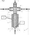
Figure 1 shows a schematic cross section through a mixing reactor in accordance with a first embodiment of the invention; -
Figure 2 shows an enlargement ofFigure 1 around the junction of the inner and outer passages; -
Figures 3a and 3b each show a corresponding view of that ofFigure 2 , for two alternative embodiments of the invention; -
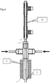
Figure 4 shows the mixing reactor ofFigure 1 being used in series with a heat exchanger; -
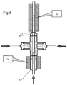
Figure 5 shows the mixing reactor ofFigure 1 being used in series with a heater; -
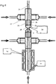
Figure 6 shows the mixing reactor being used in cascade with another mixing reactor; and -
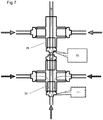
Figure 7 shows a cascade of two mixing reactors in accordance with a further embodiment of the invention. -
Figures 1 and2 show a mixingreactor 1 in accordance with a first aspect of the invention. It comprises ametal body 2 having afirst inlet 3 in afirst end 12 of the body and twosecond inlets 5 and anoutlet 4 in a second end of the body. Thebody 2 is generally elongate and has alength 15, and anouter surface 14 separating the two ends 12, 13. The reactor is used with thesecond end 13 uppermost (that is as if the accompanying drawings were viewed vertically). - An
inner passage 6 runs from thefirst inlet 3 to theoutlet 4 along the length. Twoouter passages 7 run from respectivesecond inlets 5 at the second end of the body to ajunction 11 at the first end of body, where they each enter theinner passage 6. Theouter passages 7 lie between theinner passage 6 and theouter surface 14. - As can be seen in more detail in
Figure 2 of the accompanying drawings, theouter passages 7 join theinner passage 6 throughrespective orifices 16 in theside walls 17 of theinner passage 6. In each case, there is a short length ofouter passage 7a that is perpendicular to thelength 15 and hence theinner passage 6. - Thus, if a metal salt solution is introduced into the
first inlet 3, and preheated supercritical water (or other suitable fluid such as alcohol) is introduced into thesecond inlets 5, the supercritical water will pass throughouter passages 7 until it reaches theorifices 16. At this point, the supercritical water will be introduced into the stream of metal salt solution that is passing from thefirst inlet 3 through theinner passage 6. Because of the perpendicular introduction, turbulence will be induced at thejunction 11, leading to mixing of the metal salt solution and the supercritical water. The mixing is consistent, symmetrical and thorough, leading to a satisfactory yield of consistent nanoparticles. The turbulence and consequent mixing continues as the mixed fluid passes up theinner passage 6 towards theoutlet 4, aided by the differences in density and viscosity between the two fluids. There is no need to employ mechanical impellers or the like. The nanoparticle-bearing suspension can then be extracted from theoutlet 4. - Furthermore, we have found that by appropriate control of the size d of the
apertures 16, and the flow rate of the supercritical fluid, "backflow" (that is, flow of the metal salt solution into the outer passages) can be substantially eliminated. Thus, we can avoid the formation of nanoparticles in undesired locations. As such, the flow rate of the supercritical fluid needs to be high enough to avoid backflow, and the size d of the orifices should be small enough to avoid backflow. A high flow rate and a small orifice will lead to increased turbulence and so more homogeneous mixing, although too small an orifice will lead to back-pressure issues with pumping the supercritical fluid. There are several parameters which may need to be considered when choosing the flow rate, including the flow rate of the metal salt solution, the relative diameters of thepassages perpendicular lengths 7a of the outer passages. - It can be seen that the
passages inner passage 6. This means that the mixing is symmetrical, which we have appreciated as being important when generating the best products in terms of composition, uniform particle sizes and narrow particle size distribution. The whole flow can be very quickly and evenly mixed together. - In order to keep the supercritical water hot, there is a provided a
band heater 10 around thesurface 14. This therefore preferentially heats theouter passages 7 and so their contents, the supercritical water. Because theheater 10 does not extend to thefirst inlet 3 or across thefirst end 3, there is no significant heating of the metal salt before reaching thejunction 11. Unwanted heating can lead to precipitation of the metal salts out of solution and can effect the formation of nanoparticles, as well as leading to pumping problems. On the other hand, there is little opportunity for the supercritical water to cool having passed through the outer passage adjacent to the heater, and so will be at the correct temperature for the reaction. Any heat loss between thesecond inlets 5 and theheater 10 can be mitigated by using suitable thermal lagging. - It can be seen that the present reactor provides little opportunity for particle accumulation and/or lining of internal surfaces of the reactor, which are most likely to occur where the product stream is hot. The potential for particle accumulation can be minimised by avoiding narrow constrictions, artefacts such as edges, ridges and corners (on the internal surfaces of the apparatus) and changes in overall flow direction in the region of apparatus between the mixing point (that is, the junction 11) and where the product stream is cooled after the
outlet 4. The present design allows for a reactor that is completely free of zones which may allow particle accumulation. The present reactor can be made substantially seamless and without any loss of symmetry between thejunction 11 and the point where the product has been substantially cooled in, for example, a downstream heat exchanger. - The angle at which the supercritical water flow is introduced can be varied as shown in the alternative embodiments shown in
Figures 3a and 3b of the accompanying drawings. In these, thepart orifices 16 can be angled against the flow from the first inlet as shown inFigure 3a , or with the flow as shown inFigure 3b , as long as a substantial perpendicular element is still maintained. - The mixing
reactor 1 can be used in series with various other equipment without deleterious effect on the advantages it provides. As shown inFigure 4 of the accompanying drawings, aheat exchanger 20 is connected around anextension tube 21 extending, typically seamlessly from theoutlet 4. Thus, the nanoparticle-bearing suspension can be cooled without presenting significant opportunity for blockages to form. - Likewise, if it is desired to keep the nanoparticle-bearing suspension hot, a further heater 22 can be provided around the
extension tube 21. Again, there is little opportunity for nanoparticle agglomerations to form. - In
Figure 6 , the mixingreactor 1 of the first embodiment of the invention is employed in series with asecond mixing reactor 25. Thesecond mixing reactor 25 functions in a similar way to that 1 of the first embodiment, except that it is not provided with aheater 10. As such, theoutlet 4 of thefirst mixing reactor 1 is coupled to thefirst inlet 26 of the second mixing reactor. A further fluid, for example, a secondary metal salt solution, or a solution containing a "capping agent", including but not limited to organic acids (e.g. citric acid), thiols (e.g. methanethiol) and polymers (e.g. polyvinylpyrrolidone), is introduced to thesecond inlets 27 of the second mixing reactor. The inner 28 and outer 29 passages of the second mixing reactor meet at ajunction 30 in the same manner as in the first embodiment, thejunction 30 providing a second mixing point. The further processed suspension then can be extracted from the second mixing reactor'soutlet 31. - It should be noted also that the reactor, in both its first embodiment of
Figures 1 and2 and in the multi-stage configuration ofFigure 6 need not have aouter surface 14 with aband heater 10; the heated feed can instead be introduced using only cross-pieces and reducers (in this case a cross-piece is favoured significantly over a T-piece in order to achieve symmetrical mixing, as there is little distance for the heated flow to become uniform). The use of anouter surface 14 with a band heater 10 (as inFigure 1 ) is likely to be favoured in certain scenarios (such as where increased residence time is required or the heated feed must be very hot), whereas the design without an outer surface and heater (as in the second mixing reactor ofFigure 6 ) is likely to suit other situations (where lower temperatures and/or short residence times are required). An example where both the mixingreactors heater 10 around thesurface 14 is shown inFigure 7 .
Claims (14)
- A mixing reactor (1), the reactor (1) comprising a body (2) having a first inlet (3) for a first fluid, a second inlet (5) for a second fluid and an outlet (4), in which there is an inner passage (6) through the body (2) from the first inlet (3) at a first end (12) of the body (2) to the outlet (4) at a second end (13) of the body (2) along a length (15) of the body (2), the inner passage (6) having a side wall (17) along the length (15), and an outer passage (7) closer to a surface (14) of the body (2) than the inner passage (6), the outer passage (7) running from the second inlet (5) at the second end (13), travelling through the body (2) along the length (15) and meeting the inner passage (6) at a junction (11) at the first end (12), the outer passage (7) joining the inner passage (6) through the side wall (17) at the junction (11), in which the outer passage (7) enters the inner passage (6) at an angle of 90 degrees to the length (15), plus or minus 45 degrees, characterized in that the junction is constructed such that, in use, the mixing reactor introduces the second fluid perpendicularly, plus or minus 45 degrees, to the flow of the first fluid.
- The mixing reactor (1) of claim 1, in which the junction (11) comprises an orifice (16) in the inner passage (6), with a portion of the outer passage (7) preceding the orifice (16) that is at the angle relative to the length (15).
- The mixing reactor (1) of any preceding claim, comprising a further outer passage (7) that is also closer to the surface (14) than the inner passage (6), the further outer passage (7) having a further second inlet (5) at the second end (13), travelling through the body (2) along the length (15) and meeting the inner passage (6) at a further junction (11) at the first end (12), the further outer passage (7) joining the inner passage (6) through the side wall (17) at the further junction (11).
- The mixing reactor (1) of claim 3, in which the further outer passage (7) is symmetrical to the outer passage (7) relative to the inner passage (6).
- The mixing reactor (1) of any preceding claim, comprising a heater (10) coupled to the surface (14).
- The mixing reactor (1) of any preceding claim, comprising an extension passage (21), extending out of the body (2) from the outlet (4) provided with heating or cooling apparatus through which the extension passage (21) passes.
- A cascade of mixing reactors, comprising a first mixing reactor (1) in accordance with any preceding claim and a second mixing reactor (1) in accordance with any preceding claim, in which the outlet (4) of the first mixing reactor (1) is coupled to the first inlet (3) of the second mixing reactor (1).
- A method of mixing two fluids, comprising delivering a first fluid through the first inlet (3) of a mixing reactor (1) in accordance with any of claims 1 to 6, delivering a second fluid through the second inlet (5) of the mixing reactor (1) and extracting a mixed fluid from the outlet (4)
in which the mixing reactor introduces the second fluid perpendicularly, plus or minus 45 degrees, to the flow of the first fluid. - The method of claim 8, in which the first fluid is a metal salt solution.
- The method of claim 8 or claim 9, in which the mixed fluid is a particle-bearing suspension, the particles preferably being nano-particles or metal-organic framework particles.
- The method of any of claims 8 to 10, comprising heating the second fluid through the application of heat to the surface (14) of the reactor (1).
- The method of any of claims 8 to 11, in which the reactor (1) is used with the second end (13) uppermost.
- The method of any of claims 8 to 12, in which the second fluid is water, typically supercritical water, or comprises an organic solvent such as an alcohol.
- The method of any of claims 9 to 13, comprising passing the mixed fluid through a further mixing reactor (1) in accordance with any of claims 1 to 7, in which the mixed fluid is introduced to the first inlet (3) of the further mixing reactor (1), a third fluid is introduced at the second inlet (5) of the further mixing reactor (1) and a further mixed fluid is extracted at the outlet (4) of the further mixing reactor (1).
Applications Claiming Priority (2)
| Application Number | Priority Date | Filing Date | Title |
|---|---|---|---|
| GBGB1320417.7A GB201320417D0 (en) | 2013-11-19 | 2013-11-19 | Mixing reactors |
| PCT/GB2014/053413 WO2015075439A1 (en) | 2013-11-19 | 2014-11-19 | Mixing reactor and method |
Publications (2)
| Publication Number | Publication Date |
|---|---|
| EP3071320A1 EP3071320A1 (en) | 2016-09-28 |
| EP3071320B1 true EP3071320B1 (en) | 2020-11-18 |
Family
ID=49883857
Family Applications (1)
| Application Number | Title | Priority Date | Filing Date |
|---|---|---|---|
| EP14820913.3A Active EP3071320B1 (en) | 2013-11-19 | 2014-11-19 | Mixing reactor and method |
Country Status (6)
| Country | Link |
|---|---|
| US (1) | US10406499B2 (en) |
| EP (1) | EP3071320B1 (en) |
| JP (2) | JP2016538995A (en) |
| KR (1) | KR102405044B1 (en) |
| GB (1) | GB201320417D0 (en) |
| WO (1) | WO2015075439A1 (en) |
Families Citing this family (6)
| Publication number | Priority date | Publication date | Assignee | Title |
|---|---|---|---|---|
| GB201320417D0 (en) | 2013-11-19 | 2014-01-01 | Univ Nottingham | Mixing reactors |
| KR101930234B1 (en) * | 2016-10-12 | 2018-12-18 | 최종문 | Device for discharging and mixing fluids |
| GB201721808D0 (en) * | 2017-12-22 | 2018-02-07 | Sensient Colors Uk Ltd | Nanaoparticle dispersions |
| GB201811076D0 (en) | 2018-07-05 | 2018-08-22 | Sensient Colors Uk Ltd | Nanoparticle dispersions |
| GB202201007D0 (en) | 2022-01-26 | 2022-03-09 | Micropore Tech Ltd | Methods for reactive crystallisation |
| WO2023218221A1 (en) * | 2022-05-08 | 2023-11-16 | Alibouri Mehrdad | Jet mixer reactor |
Family Cites Families (10)
| Publication number | Priority date | Publication date | Assignee | Title |
|---|---|---|---|---|
| US4124353A (en) * | 1975-06-27 | 1978-11-07 | Rhone-Poulenc Industries | Method and apparatus for carrying out a reaction between streams of fluid |
| JP4197448B2 (en) * | 2003-04-02 | 2008-12-17 | 株式会社日立製作所 | Heavy oil treatment equipment using supercritical water and power generation system equipped with heavy oil treatment equipment |
| FR2858248B1 (en) * | 2003-07-29 | 2005-10-28 | Jeumont Sa | DEVICE FOR MIXING TWO FLUIDS AND USE FOR COOLING A VERY HIGH TEMPERATURE FLUID |
| GB0402963D0 (en) | 2004-02-11 | 2004-03-17 | Univ Nottingham | Counter current mixing device for two different fluids |
| DE102006015708B4 (en) * | 2006-04-04 | 2008-08-21 | Fraunhofer-Gesellschaft zur Förderung der angewandten Forschung e.V. | Device for supercritical wet oxidation |
| US8496786B2 (en) | 2009-12-15 | 2013-07-30 | Stone & Webster Process Technology, Inc. | Heavy feed mixer |
| WO2011148121A1 (en) | 2010-05-25 | 2011-12-01 | Ucl Business Plc | Co -current mixer, apparatus, reactor and method for precipitaing nanoparticles |
| FR2979842B1 (en) * | 2011-09-09 | 2013-10-04 | Commissariat Energie Atomique | PROCESS FOR THE CONTINUOUS SYNTHESIS OF METAL OXIDE NANOPARTICLES BY HYDROTHERMAL REACTION IN A SUPERCRITICAL ENVIRONMENT |
| JP2013136045A (en) * | 2011-11-28 | 2013-07-11 | Ricoh Co Ltd | Apparatus and method for treatment of waste liquid |
| GB201320417D0 (en) | 2013-11-19 | 2014-01-01 | Univ Nottingham | Mixing reactors |
-
2013
- 2013-11-19 GB GBGB1320417.7A patent/GB201320417D0/en not_active Ceased
-
2014
- 2014-11-19 JP JP2016532596A patent/JP2016538995A/en active Pending
- 2014-11-19 US US15/037,520 patent/US10406499B2/en active Active
- 2014-11-19 WO PCT/GB2014/053413 patent/WO2015075439A1/en active Application Filing
- 2014-11-19 KR KR1020167016065A patent/KR102405044B1/en active IP Right Grant
- 2014-11-19 EP EP14820913.3A patent/EP3071320B1/en active Active
-
2020
- 2020-01-16 JP JP2020004996A patent/JP7013040B2/en active Active
Non-Patent Citations (1)
| Title |
|---|
| None * |
Also Published As
| Publication number | Publication date |
|---|---|
| WO2015075439A1 (en) | 2015-05-28 |
| JP7013040B2 (en) | 2022-01-31 |
| US10406499B2 (en) | 2019-09-10 |
| GB201320417D0 (en) | 2014-01-01 |
| EP3071320A1 (en) | 2016-09-28 |
| JP2016538995A (en) | 2016-12-15 |
| JP2020073268A (en) | 2020-05-14 |
| KR102405044B1 (en) | 2022-06-02 |
| KR20160087853A (en) | 2016-07-22 |
| US20160279589A1 (en) | 2016-09-29 |
Similar Documents
| Publication | Publication Date | Title |
|---|---|---|
| EP3071320B1 (en) | Mixing reactor and method | |
| US10722860B2 (en) | Mixing reactor and related process | |
| CN103831074B (en) | Counter current mixing reactor | |
| EP2576036B1 (en) | Co-current mixer and method for precipitating nanoparticles | |
| WO1998002237A1 (en) | Production of powders | |
| Li et al. | Hydrothermal micro continuous-flow synthesis of spherical, cylinder-, star-and flower-like ZnO microparticles | |
| JP2008012453A (en) | High-temperature high-pressure micromixer | |
| JP2005046651A (en) | Reaction method using microreactor | |
| Wu et al. | Continuous synthesis of hollow silver–palladium nanoparticles for catalytic applications | |
| AU2008246295B2 (en) | Injector assembly, chemical reactor and chemical process | |
| US20160074823A1 (en) | Co current mixer, apparatus, reactor and method for precipitating nanoparticles | |
| JP4724619B2 (en) | Fluid processing apparatus and fluid processing method | |
| Jiang et al. | High throughput continuous synthesis of size-controlled nanoFe3O4 in segmented flow | |
| TW201029931A (en) | Manufacturing method of metal oxide particles and manufacturing device for the same | |
| Lester et al. | Advancements in the supercritical water hydrothermal synthesis (scWHS) of metal oxide nanoparticles | |
| JP2002292271A (en) | Flow type fine reaction passage, reaction apparatus and reaction method | |
| JPS63171638A (en) | Chemical reaction in flow inside of pipe with precise control | |
| CN115554942A (en) | Micro-reactor for intensifying mixing process | |
| Sebastián Cabeza | Advances in microfluidics-New applications in biology, energy, and materials sciences. Chap 17: High and Efficient Production of Nanomaterials by Microfluidic Reactor Approaches |
Legal Events
| Date | Code | Title | Description |
|---|---|---|---|
| PUAI | Public reference made under article 153(3) epc to a published international application that has entered the european phase |
Free format text: ORIGINAL CODE: 0009012 |
|
| 17P | Request for examination filed |
Effective date: 20160615 |
|
| AK | Designated contracting states |
Kind code of ref document: A1 Designated state(s): AL AT BE BG CH CY CZ DE DK EE ES FI FR GB GR HR HU IE IS IT LI LT LU LV MC MK MT NL NO PL PT RO RS SE SI SK SM TR |
|
| AX | Request for extension of the european patent |
Extension state: BA ME |
|
| DAX | Request for extension of the european patent (deleted) | ||
| STAA | Information on the status of an ep patent application or granted ep patent |
Free format text: STATUS: EXAMINATION IS IN PROGRESS |
|
| 17Q | First examination report despatched |
Effective date: 20171024 |
|
| GRAP | Despatch of communication of intention to grant a patent |
Free format text: ORIGINAL CODE: EPIDOSNIGR1 |
|
| STAA | Information on the status of an ep patent application or granted ep patent |
Free format text: STATUS: GRANT OF PATENT IS INTENDED |
|
| INTG | Intention to grant announced |
Effective date: 20200703 |
|
| GRAS | Grant fee paid |
Free format text: ORIGINAL CODE: EPIDOSNIGR3 |
|
| RAP1 | Party data changed (applicant data changed or rights of an application transferred) |
Owner name: PROMETHEAN PARTICLES LIMITED |
|
| GRAA | (expected) grant |
Free format text: ORIGINAL CODE: 0009210 |
|
| STAA | Information on the status of an ep patent application or granted ep patent |
Free format text: STATUS: THE PATENT HAS BEEN GRANTED |
|
| AK | Designated contracting states |
Kind code of ref document: B1 Designated state(s): AL AT BE BG CH CY CZ DE DK EE ES FI FR GB GR HR HU IE IS IT LI LT LU LV MC MK MT NL NO PL PT RO RS SE SI SK SM TR |
|
| REG | Reference to a national code |
Ref country code: GB Ref legal event code: FG4D |
|
| REG | Reference to a national code |
Ref country code: CH Ref legal event code: EP |
|
| REG | Reference to a national code |
Ref country code: IE Ref legal event code: FG4D |
|
| REG | Reference to a national code |
Ref country code: DE Ref legal event code: R096 Ref document number: 602014072528 Country of ref document: DE |
|
| REG | Reference to a national code |
Ref country code: AT Ref legal event code: REF Ref document number: 1335127 Country of ref document: AT Kind code of ref document: T Effective date: 20201215 |
|
| REG | Reference to a national code |
Ref country code: AT Ref legal event code: MK05 Ref document number: 1335127 Country of ref document: AT Kind code of ref document: T Effective date: 20201118 |
|
| REG | Reference to a national code |
Ref country code: NL Ref legal event code: MP Effective date: 20201118 |
|
| PG25 | Lapsed in a contracting state [announced via postgrant information from national office to epo] |
Ref country code: PT Free format text: LAPSE BECAUSE OF FAILURE TO SUBMIT A TRANSLATION OF THE DESCRIPTION OR TO PAY THE FEE WITHIN THE PRESCRIBED TIME-LIMIT Effective date: 20210318 Ref country code: NO Free format text: LAPSE BECAUSE OF FAILURE TO SUBMIT A TRANSLATION OF THE DESCRIPTION OR TO PAY THE FEE WITHIN THE PRESCRIBED TIME-LIMIT Effective date: 20210218 Ref country code: RS Free format text: LAPSE BECAUSE OF FAILURE TO SUBMIT A TRANSLATION OF THE DESCRIPTION OR TO PAY THE FEE WITHIN THE PRESCRIBED TIME-LIMIT Effective date: 20201118 Ref country code: FI Free format text: LAPSE BECAUSE OF FAILURE TO SUBMIT A TRANSLATION OF THE DESCRIPTION OR TO PAY THE FEE WITHIN THE PRESCRIBED TIME-LIMIT Effective date: 20201118 Ref country code: GR Free format text: LAPSE BECAUSE OF FAILURE TO SUBMIT A TRANSLATION OF THE DESCRIPTION OR TO PAY THE FEE WITHIN THE PRESCRIBED TIME-LIMIT Effective date: 20210219 |
|
| PG25 | Lapsed in a contracting state [announced via postgrant information from national office to epo] |
Ref country code: IS Free format text: LAPSE BECAUSE OF FAILURE TO SUBMIT A TRANSLATION OF THE DESCRIPTION OR TO PAY THE FEE WITHIN THE PRESCRIBED TIME-LIMIT Effective date: 20210318 Ref country code: PL Free format text: LAPSE BECAUSE OF FAILURE TO SUBMIT A TRANSLATION OF THE DESCRIPTION OR TO PAY THE FEE WITHIN THE PRESCRIBED TIME-LIMIT Effective date: 20201118 Ref country code: LV Free format text: LAPSE BECAUSE OF FAILURE TO SUBMIT A TRANSLATION OF THE DESCRIPTION OR TO PAY THE FEE WITHIN THE PRESCRIBED TIME-LIMIT Effective date: 20201118 Ref country code: SE Free format text: LAPSE BECAUSE OF FAILURE TO SUBMIT A TRANSLATION OF THE DESCRIPTION OR TO PAY THE FEE WITHIN THE PRESCRIBED TIME-LIMIT Effective date: 20201118 Ref country code: BG Free format text: LAPSE BECAUSE OF FAILURE TO SUBMIT A TRANSLATION OF THE DESCRIPTION OR TO PAY THE FEE WITHIN THE PRESCRIBED TIME-LIMIT Effective date: 20210218 Ref country code: AT Free format text: LAPSE BECAUSE OF FAILURE TO SUBMIT A TRANSLATION OF THE DESCRIPTION OR TO PAY THE FEE WITHIN THE PRESCRIBED TIME-LIMIT Effective date: 20201118 |
|
| REG | Reference to a national code |
Ref country code: LT Ref legal event code: MG9D |
|
| PG25 | Lapsed in a contracting state [announced via postgrant information from national office to epo] |
Ref country code: HR Free format text: LAPSE BECAUSE OF FAILURE TO SUBMIT A TRANSLATION OF THE DESCRIPTION OR TO PAY THE FEE WITHIN THE PRESCRIBED TIME-LIMIT Effective date: 20201118 |
|
| REG | Reference to a national code |
Ref country code: CH Ref legal event code: PL |
|
| PG25 | Lapsed in a contracting state [announced via postgrant information from national office to epo] |
Ref country code: RO Free format text: LAPSE BECAUSE OF FAILURE TO SUBMIT A TRANSLATION OF THE DESCRIPTION OR TO PAY THE FEE WITHIN THE PRESCRIBED TIME-LIMIT Effective date: 20201118 Ref country code: SK Free format text: LAPSE BECAUSE OF FAILURE TO SUBMIT A TRANSLATION OF THE DESCRIPTION OR TO PAY THE FEE WITHIN THE PRESCRIBED TIME-LIMIT Effective date: 20201118 Ref country code: LT Free format text: LAPSE BECAUSE OF FAILURE TO SUBMIT A TRANSLATION OF THE DESCRIPTION OR TO PAY THE FEE WITHIN THE PRESCRIBED TIME-LIMIT Effective date: 20201118 Ref country code: SM Free format text: LAPSE BECAUSE OF FAILURE TO SUBMIT A TRANSLATION OF THE DESCRIPTION OR TO PAY THE FEE WITHIN THE PRESCRIBED TIME-LIMIT Effective date: 20201118 Ref country code: EE Free format text: LAPSE BECAUSE OF FAILURE TO SUBMIT A TRANSLATION OF THE DESCRIPTION OR TO PAY THE FEE WITHIN THE PRESCRIBED TIME-LIMIT Effective date: 20201118 Ref country code: CZ Free format text: LAPSE BECAUSE OF FAILURE TO SUBMIT A TRANSLATION OF THE DESCRIPTION OR TO PAY THE FEE WITHIN THE PRESCRIBED TIME-LIMIT Effective date: 20201118 Ref country code: LU Free format text: LAPSE BECAUSE OF NON-PAYMENT OF DUE FEES Effective date: 20201119 |
|
| REG | Reference to a national code |
Ref country code: BE Ref legal event code: MM Effective date: 20201130 |
|
| REG | Reference to a national code |
Ref country code: DE Ref legal event code: R097 Ref document number: 602014072528 Country of ref document: DE |
|
| PG25 | Lapsed in a contracting state [announced via postgrant information from national office to epo] |
Ref country code: DK Free format text: LAPSE BECAUSE OF FAILURE TO SUBMIT A TRANSLATION OF THE DESCRIPTION OR TO PAY THE FEE WITHIN THE PRESCRIBED TIME-LIMIT Effective date: 20201118 Ref country code: CH Free format text: LAPSE BECAUSE OF NON-PAYMENT OF DUE FEES Effective date: 20201130 Ref country code: MC Free format text: LAPSE BECAUSE OF FAILURE TO SUBMIT A TRANSLATION OF THE DESCRIPTION OR TO PAY THE FEE WITHIN THE PRESCRIBED TIME-LIMIT Effective date: 20201118 Ref country code: LI Free format text: LAPSE BECAUSE OF NON-PAYMENT OF DUE FEES Effective date: 20201130 |
|
| PLBE | No opposition filed within time limit |
Free format text: ORIGINAL CODE: 0009261 |
|
| STAA | Information on the status of an ep patent application or granted ep patent |
Free format text: STATUS: NO OPPOSITION FILED WITHIN TIME LIMIT |
|
| 26N | No opposition filed |
Effective date: 20210819 |
|
| PG25 | Lapsed in a contracting state [announced via postgrant information from national office to epo] |
Ref country code: AL Free format text: LAPSE BECAUSE OF FAILURE TO SUBMIT A TRANSLATION OF THE DESCRIPTION OR TO PAY THE FEE WITHIN THE PRESCRIBED TIME-LIMIT Effective date: 20201118 Ref country code: NL Free format text: LAPSE BECAUSE OF FAILURE TO SUBMIT A TRANSLATION OF THE DESCRIPTION OR TO PAY THE FEE WITHIN THE PRESCRIBED TIME-LIMIT Effective date: 20201118 Ref country code: IT Free format text: LAPSE BECAUSE OF FAILURE TO SUBMIT A TRANSLATION OF THE DESCRIPTION OR TO PAY THE FEE WITHIN THE PRESCRIBED TIME-LIMIT Effective date: 20201118 Ref country code: IE Free format text: LAPSE BECAUSE OF NON-PAYMENT OF DUE FEES Effective date: 20201119 |
|
| REG | Reference to a national code |
Ref country code: DE Ref legal event code: R079 Ref document number: 602014072528 Country of ref document: DE Free format text: PREVIOUS MAIN CLASS: B01F0005040000 Ipc: B01F0025300000 |
|
| PG25 | Lapsed in a contracting state [announced via postgrant information from national office to epo] |
Ref country code: ES Free format text: LAPSE BECAUSE OF FAILURE TO SUBMIT A TRANSLATION OF THE DESCRIPTION OR TO PAY THE FEE WITHIN THE PRESCRIBED TIME-LIMIT Effective date: 20201118 Ref country code: SI Free format text: LAPSE BECAUSE OF FAILURE TO SUBMIT A TRANSLATION OF THE DESCRIPTION OR TO PAY THE FEE WITHIN THE PRESCRIBED TIME-LIMIT Effective date: 20201118 |
|
| PG25 | Lapsed in a contracting state [announced via postgrant information from national office to epo] |
Ref country code: IS Free format text: LAPSE BECAUSE OF FAILURE TO SUBMIT A TRANSLATION OF THE DESCRIPTION OR TO PAY THE FEE WITHIN THE PRESCRIBED TIME-LIMIT Effective date: 20210318 Ref country code: TR Free format text: LAPSE BECAUSE OF FAILURE TO SUBMIT A TRANSLATION OF THE DESCRIPTION OR TO PAY THE FEE WITHIN THE PRESCRIBED TIME-LIMIT Effective date: 20201118 Ref country code: MT Free format text: LAPSE BECAUSE OF FAILURE TO SUBMIT A TRANSLATION OF THE DESCRIPTION OR TO PAY THE FEE WITHIN THE PRESCRIBED TIME-LIMIT Effective date: 20201118 Ref country code: CY Free format text: LAPSE BECAUSE OF FAILURE TO SUBMIT A TRANSLATION OF THE DESCRIPTION OR TO PAY THE FEE WITHIN THE PRESCRIBED TIME-LIMIT Effective date: 20201118 |
|
| PG25 | Lapsed in a contracting state [announced via postgrant information from national office to epo] |
Ref country code: MK Free format text: LAPSE BECAUSE OF FAILURE TO SUBMIT A TRANSLATION OF THE DESCRIPTION OR TO PAY THE FEE WITHIN THE PRESCRIBED TIME-LIMIT Effective date: 20201118 |
|
| PG25 | Lapsed in a contracting state [announced via postgrant information from national office to epo] |
Ref country code: BE Free format text: LAPSE BECAUSE OF NON-PAYMENT OF DUE FEES Effective date: 20201130 |
|
| PGFP | Annual fee paid to national office [announced via postgrant information from national office to epo] |
Ref country code: GB Payment date: 20231129 Year of fee payment: 10 |
|
| PGFP | Annual fee paid to national office [announced via postgrant information from national office to epo] |
Ref country code: FR Payment date: 20231109 Year of fee payment: 10 Ref country code: DE Payment date: 20231108 Year of fee payment: 10 |