EP3069065B1 - Fluid transmission coupling with independent member pressure relieving cam - Google Patents
Fluid transmission coupling with independent member pressure relieving cam Download PDFInfo
- Publication number
- EP3069065B1 EP3069065B1 EP14798774.7A EP14798774A EP3069065B1 EP 3069065 B1 EP3069065 B1 EP 3069065B1 EP 14798774 A EP14798774 A EP 14798774A EP 3069065 B1 EP3069065 B1 EP 3069065B1
- Authority
- EP
- European Patent Office
- Prior art keywords
- coupler
- fitting
- female
- female coupler
- attachment portion
- Prior art date
- Legal status (The legal status is an assumption and is not a legal conclusion. Google has not performed a legal analysis and makes no representation as to the accuracy of the status listed.)
- Active
Links
- 239000012530 fluid Substances 0.000 title claims description 22
- 230000005540 biological transmission Effects 0.000 title claims description 11
- 230000008878 coupling Effects 0.000 title description 28
- 238000010168 coupling process Methods 0.000 title description 28
- 238000005859 coupling reaction Methods 0.000 title description 28
- 230000000284 resting effect Effects 0.000 claims description 6
- 238000004891 communication Methods 0.000 claims description 4
- 238000006073 displacement reaction Methods 0.000 description 5
- 238000007789 sealing Methods 0.000 description 3
- 230000000694 effects Effects 0.000 description 2
- 230000003993 interaction Effects 0.000 description 2
- 238000011144 upstream manufacturing Methods 0.000 description 2
- 230000000295 complement effect Effects 0.000 description 1
- 230000006835 compression Effects 0.000 description 1
- 238000007906 compression Methods 0.000 description 1
- 238000007599 discharging Methods 0.000 description 1
- 238000003780 insertion Methods 0.000 description 1
- 230000037431 insertion Effects 0.000 description 1
- 239000000463 material Substances 0.000 description 1
- 238000000034 method Methods 0.000 description 1
- 238000013022 venting Methods 0.000 description 1
Images


Classifications
-
- F—MECHANICAL ENGINEERING; LIGHTING; HEATING; WEAPONS; BLASTING
- F16—ENGINEERING ELEMENTS AND UNITS; GENERAL MEASURES FOR PRODUCING AND MAINTAINING EFFECTIVE FUNCTIONING OF MACHINES OR INSTALLATIONS; THERMAL INSULATION IN GENERAL
- F16K—VALVES; TAPS; COCKS; ACTUATING-FLOATS; DEVICES FOR VENTING OR AERATING
- F16K11/00—Multiple-way valves, e.g. mixing valves; Pipe fittings incorporating such valves
- F16K11/10—Multiple-way valves, e.g. mixing valves; Pipe fittings incorporating such valves with two or more closure members not moving as a unit
- F16K11/14—Multiple-way valves, e.g. mixing valves; Pipe fittings incorporating such valves with two or more closure members not moving as a unit operated by one actuating member, e.g. a handle
- F16K11/18—Multiple-way valves, e.g. mixing valves; Pipe fittings incorporating such valves with two or more closure members not moving as a unit operated by one actuating member, e.g. a handle with separate operating movements for separate closure members
-
- F—MECHANICAL ENGINEERING; LIGHTING; HEATING; WEAPONS; BLASTING
- F16—ENGINEERING ELEMENTS AND UNITS; GENERAL MEASURES FOR PRODUCING AND MAINTAINING EFFECTIVE FUNCTIONING OF MACHINES OR INSTALLATIONS; THERMAL INSULATION IN GENERAL
- F16L—PIPES; JOINTS OR FITTINGS FOR PIPES; SUPPORTS FOR PIPES, CABLES OR PROTECTIVE TUBING; MEANS FOR THERMAL INSULATION IN GENERAL
- F16L37/00—Couplings of the quick-acting type
- F16L37/28—Couplings of the quick-acting type with fluid cut-off means
- F16L37/30—Couplings of the quick-acting type with fluid cut-off means with fluid cut-off means in each of two pipe-end fittings
- F16L37/32—Couplings of the quick-acting type with fluid cut-off means with fluid cut-off means in each of two pipe-end fittings at least one of two lift valves being opened automatically when the coupling is applied
-
- F—MECHANICAL ENGINEERING; LIGHTING; HEATING; WEAPONS; BLASTING
- F16—ENGINEERING ELEMENTS AND UNITS; GENERAL MEASURES FOR PRODUCING AND MAINTAINING EFFECTIVE FUNCTIONING OF MACHINES OR INSTALLATIONS; THERMAL INSULATION IN GENERAL
- F16K—VALVES; TAPS; COCKS; ACTUATING-FLOATS; DEVICES FOR VENTING OR AERATING
- F16K11/00—Multiple-way valves, e.g. mixing valves; Pipe fittings incorporating such valves
- F16K11/10—Multiple-way valves, e.g. mixing valves; Pipe fittings incorporating such valves with two or more closure members not moving as a unit
- F16K11/14—Multiple-way valves, e.g. mixing valves; Pipe fittings incorporating such valves with two or more closure members not moving as a unit operated by one actuating member, e.g. a handle
- F16K11/18—Multiple-way valves, e.g. mixing valves; Pipe fittings incorporating such valves with two or more closure members not moving as a unit operated by one actuating member, e.g. a handle with separate operating movements for separate closure members
- F16K11/185—Multiple-way valves, e.g. mixing valves; Pipe fittings incorporating such valves with two or more closure members not moving as a unit operated by one actuating member, e.g. a handle with separate operating movements for separate closure members with swinging shafts
-
- F—MECHANICAL ENGINEERING; LIGHTING; HEATING; WEAPONS; BLASTING
- F16—ENGINEERING ELEMENTS AND UNITS; GENERAL MEASURES FOR PRODUCING AND MAINTAINING EFFECTIVE FUNCTIONING OF MACHINES OR INSTALLATIONS; THERMAL INSULATION IN GENERAL
- F16L—PIPES; JOINTS OR FITTINGS FOR PIPES; SUPPORTS FOR PIPES, CABLES OR PROTECTIVE TUBING; MEANS FOR THERMAL INSULATION IN GENERAL
- F16L37/00—Couplings of the quick-acting type
- F16L37/22—Couplings of the quick-acting type in which the connection is maintained by means of balls, rollers or helical springs under radial pressure between the parts
- F16L37/23—Couplings of the quick-acting type in which the connection is maintained by means of balls, rollers or helical springs under radial pressure between the parts by means of balls
-
- F—MECHANICAL ENGINEERING; LIGHTING; HEATING; WEAPONS; BLASTING
- F16—ENGINEERING ELEMENTS AND UNITS; GENERAL MEASURES FOR PRODUCING AND MAINTAINING EFFECTIVE FUNCTIONING OF MACHINES OR INSTALLATIONS; THERMAL INSULATION IN GENERAL
- F16L—PIPES; JOINTS OR FITTINGS FOR PIPES; SUPPORTS FOR PIPES, CABLES OR PROTECTIVE TUBING; MEANS FOR THERMAL INSULATION IN GENERAL
- F16L37/00—Couplings of the quick-acting type
- F16L37/56—Couplings of the quick-acting type for double-walled or multi-channel pipes or pipe assemblies
Definitions
- the present invention relates to a fluid transmission coupling with independent member pressure relieving cam.
- Fittings which may be rapidly coupled to one another to connect a fluid feed, by means of rigid pipes or flexible hoses, are frequently required for fluid transmission for example in operating machines and hydraulic equipment.
- the known quick coupling fittings usually consist of two couplings, named male and female, which are fastened to respective pipes to be joined and which can be coupled together by screwing or by snapping.
- the aforesaid male and female couplers are formed by fixed parts and axially sliding parts, which at rest are arranged in a closing position of a fluid passage gap and during the coupling between two members are displaced by engaging with corresponding parts of the other member to an opening position of said passage gap.
- Italian patent application MI2012A001254 by the present Applicant concerns a fluid transmission coupling connectable with constant effort provided with a pressure compensation and relief system which is complex and not very cost-effective.
- Said known fitting further comprises a central locking system which is mechanically cumbersome and ineffective in some situations of accidental actuating by the user.
- US-2006/0273580 describes a pressurized fluid transmission fitting with pressure relief cam having a first member which acts on a first female coupler of a first hydraulic line, in one piece with the second member which acts on a second female coupler of a second hydraulic line. As said first and second members belong to one same piece, the approaching movement of the first member to the female coupler corresponds to the distancing of the second member from the second female coupler.
- EP-0048822 shows a fluid transmission fitting with a cam with actuating members in one piece.
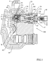
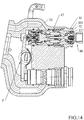
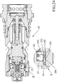
- Figure 1 shows a coupling fitting 100 comprising a female valve coupler 47 inserted in a hydraulic feeding block 1 and a male valve coupler 48 which can be coupled to said female coupler 47.
- the block 1, which feeds the fluid comprises at least one hydraulic line 49 and a draining line 50, both interfacing with one or more female couplers 47.
- the block 1 further comprises a lever 4 integral with a cam 7 adapted to relieve the pressure from a chamber 54 inside the female coupler 47, and adapted to uncouple the male coupler 48 from the female coupler 47.
- the cam 7 consists of two independent parts, an upper one 82, which acts on the coupling of the upper hydraulic line, and a lower one 83, which acts on the coupling of the lower hydraulic line ( figure 1 ).
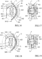
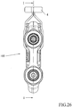
- the cams 82, 83 have one disc-shaped attachment portion 821, 831 ( figures 16-23 ) with a respective loop 822, 832 each.
- Said attachment portions 821, 831 are associated with a central shaft 5 controlled by the rotation of the lever 4, by means of said loops 822, 832 in which said central shaft 5 is housed with clearance.
- the central shaft 5 has a substantially rectangular section 501 with rounded short sides ( figure 16 ) so as to allow the rotation of said shaft 5 in the loops 822, 832.
- loops 822, 832 are similar to that of the shaft 5, but broader so as to allow the shaft 5 to move inside if it is not meshing with either one loop 822, 832 or the other, as will be more apparent below.
- loops 822, 832 are superimposed in axis with the rotation axis of the shaft 5.
- the attachment portions 821, 831 may move one over the other, thus being reciprocally independent as their rotation is controlled only by the lever 4 by means of the shaft 5.
- the rotation of the central shaft 5 is determined by applying stress to the lever 4, which moves the attachment portion 821 of the upper cam 82 clockwise, but being free in the second loop 832 it does not move the attachment portion 831 of the lower cam 83, and moves the attachment portion 831 of the lower cam 83 anticlockwise but by being free in the loop 822 it does not move the attachment portion 821 of the upper cam 82.
- the shape of said loops 822, 832 is substantially complementary to the shape of the central shaft 5, but their width is greater to allow a rotation clearance such to be able to move one cam 82 while maintaining the other 83 stationary, and vice versa, as will be more apparent below.
- the cams 82, 83 are held in position by means of the spring 71, for example a C spring, but two compression springs may be provided. It is also possible to eliminate said spring 71 because said cams 82, 83 are stressed by the shutter 25 and in all cases a slight clearance, which determines a minimal distancing from the ideal initial resting position, is tolerated ( figure 1 ).
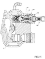
- the female coupler 47 comprises a pressure relief valve which puts said chamber 54 into communication with the draining line 50 ( figure 1 ).
- Said valve 51 comprises a valve body 23, which forms a housing for a sliding shutter 25, stressed by a spring 26, which reacts against a protrusion of the shutter 25 and a stop 27. Sealing is ensured by the contact between a conical surface 251 of the shutter 25 and an edge 231 of the valve body 23 ( figure 1 ).
- the upper cam 82 is always in contact with the cup 72, which is pushed by the spring 84 against the cam 82 in releasing position of the shutter 25. Said cup 72 is thus moveable between an engaging position and a releasing position with the shutter 25.
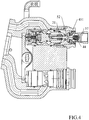
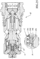
- the shutter 25 has therein a hole 252 ( figure 2 ) for venting the air and a hydraulic thrust section reduced to the minimum.
- a hydraulic thrust section is determined by the interface diameter between the conical surface 251 of the shutter 25 and the valve body 23, and by the diameter of slightly smaller size of a rear part 263 of the shutter 25 on which a seal 28 acts.
- the described configuration of the shutter 25 - valve body 23 coupling allows to minimize the actuation force of the shutter 25 itself in presence of residual pressure present inside the chamber 54.
- the female coupler 47 further comprises a valve 52 axially sliding inside an outer assembly 53 of the female coupler 47 itself, and a seal 19 adapted to generate a pressure difference between the hydraulic line 49 and the chamber 54.
- Said seal 19 is adapted to close a calibrated communication pipe 191 between the chamber 54 and the hydraulic line 49 contained in an inner body 13 ( figure 2 ).
- Said seal 19 is ring-shaped, determines a radial type sealing, i.e. orthogonal to the axis of the fitting 100, and comprises a non-deformable portion 192 and a deformable portion 193.
- Said pipe 191 is external to the chamber 54 and the pressurized fluid flow inside it assures radially outwards from the inside of the chamber 54 at the outer surface of the seal 19.
- the deformable portion 193 bends towards the inside of the chamber 54 thus determining the introduction of pressurized fluid into the chamber 54 of the hydraulic line 49.
- the deformable portion 193 returns to its initial position thus obstructing the passage of fluid.
- Said seal 19 can be used with identical operating principle also in case of flat-faced male-female couplers.
- the outer assembly 53 ( figure 1 ) comprises a ring nut holder 29, a ring nut 30 and at least one locking ball 32 arranged inside a housing of the ring nut holder 29.
- a spring 31 by reacting against appropriate protrusions 292, 302, against the ring nut 30, the ring nut holder 29 and the block 1, constrains the outer assembly 53 in a central resting position which guarantees the locking of the male coupler 48 after the coupling.
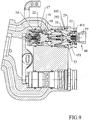
- a bottom 16 also slides inside the female coupler 47 and has two seals 14 and 17 ( figure 9 ) on the side of the hydraulic line 49 and on that of the chamber 54, respectively.
- the zone comprised between the two seals 14, 17 is in contact with the draining line 50 by means of the pipe 56.
- the bottom is held in position by a spring 22.
- the male coupler 48 is shown, in turn, in figure 1 and comprises a threaded male body 41 for connecting to a user (not shown), e.g. to a hydraulic equipment. There is a valve 451 held in position by a spring 44 which acts on a bottom 42 within the male body 41. Such a valve 451 guarantees the sealing of the male coupler 48 in uncoupled condition.
- Residual pressure may be present in one or more of the hydraulic lines 49 in operation.
- the lever 4 moves rightwards and actuates the upper cam 82, which pushes the cup 72 towards the shutter 25 putting the hydraulic line 49 into connection with the draining line 50 and allowing to relieve the inner residual pressure ( figure 2 ).
- the seal 19 is radially deformed at the deformable portion 193 allowing the passage of fluid through the pipe 191.
- the lower cam 83 does not move because the shaft 5 by rotating rightwards meets a side of the loop 822 of the upper cam 82 feeding it, while the loop 832 of the attachment portion 831 is sufficiently wide to make the shaft 5 rotate without touching any of its sides ( figures 18- 19 ).
- the attachment portion 821 of the upper cam 82 rotates on the attachment portion 831 of the lower cam 83. The upper cam 82 thus moves independently from the lower cam 83.
- the force applied by the lever 4 must be such to overcome the resistance of the spring 71, which in all cases holds the lower cam 83 in position.
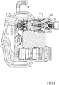
- the first coupling step ( figure 4 ) consists in pushing the male coupler 48 into the female coupler 47. Residual pressure may be present in the chamber 57 upstream of the valve 451.
- the valve 451 comes into contact with the valve 52 by approaching the male coupler 48 to the female coupler 47.
- the load of the springs 21 and 44 is equivalent and both valves 451, 52 are displaced. Only valve 52 is displaced in case of pressure in the chamber 57.
- the shutter 25 goes into contact with the cup 72 and the upper cam 82, in turn, goes into contact with the block 1.
- the shutter 25 opens and turns the hydraulic line 49 into an open circuit. This function allows to relieve the pressure during coupling even if the lever 4 is not operated in advance.
- the upper cam 82 is not free to move with the shutter 25 in the opening position.
- the spring 31 returns the assembly consisting of the outer assembly 53 and the male coupler 48 to the coupled balanced position by working on the shoulder 292 of the lock ring holder 29 ( figure 9 ).
- the bottom 16 is not moved and is held in position by the spring 22, and the valve 451 is retracted; in this case the circuit is open and the coupler is coupled as shown in figure 10 .
- the bottom 16 retracts instead in case of pressure in the chamber 57.
- the circuit totally opens when the bottom 16 abuts on the inner body 13 (again in figure 10 ). In this position, the chamber 54 remains full of oil and pressurized, and no longer allows the movement of the bottom 16 except for a movement of the shutter 25 because the seal 19 does not allow the return of fluid towards the hydraulic line 49.
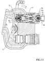
- the upper cam 82 pushes the cup 72 to act on the valve body 23, which in turn moves the whole formed by female coupler 47 and male coupler 48 outwards the locking balls 32 with the recess 303 on the fixing ring nut 30.
- the locking balls 32 exit from the recess 411 in the male body 41 and release it letting it out ( figures 13-14 ).
- the loop 832 of the lower cam 83 is sufficiently wide to allow a double movement of the upper cam 82 at the end of the second movement, the shaft 5 nearly abutting onto a side of said loop 832 ( figures 20-21 ).
- the upper cam 82 rotates by a predetermined angle according to the shape of the loop 832, and vice versa, as will be more apparent below, the lower cam 83 rotates in opposite sense by a predetermined angle according to the shape of the loop 822.
- the unrestrained male coupler 48 is uncoupled by effect of the thrust of the inner springs. Having released the balls 32, the spring 31 returns the female coupler 47 to the resting position by working on the ring 37 ( figures 15 and 1 ).
- the system is ready for a new connection.
- the female coupler 47 coupled by means of the locking balls 32 is fed outwards when coupled, if the male coupler 48 is pulled.
- the male coupler 48 is uncoupled (accidental uncoupling, "breakaway" function).
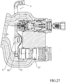
- the engagement of the lower line is similar to that of the upper line, it being worth noting that the lever 4 moves leftwards in opposite sense ( figure 27 ) starting from the central resting position shown in figure 16 ( figure 27 ): the interaction between the shaft 5 and the attachment portion 831 of the lower cam 83 is similar to that described above for the attachment portion 821 of the upper cam 82, in which the loop 822 allows the rotation of the attachment portion 831 of the lower cam 83 without moving the upper cam 82.
- FIGS 24-25 show female couplers 47 with seals 19 according to two further embodiments.
- the seal 19 in figure 24 is not placed directly on the mouth of the pipe 191, there being provided an annular gap 194 obtained on the valve body 23 which allows to limit the wear of the seal 19 itself, which again includes a non-deformable portion 192 and a deformable portion 193.
- Said gap 194 allows to direct the pressurized flow exiting from the mouth of the pipe 191 firstly towards the non-deformable portion 192, then onto the deformable portion 193, on both sides of said mouth of the pipe 191.
- Said deformable portion 193 has a reduced thickness with respect to the non-deformable portion 192, which is further reduced by moving away from the non-deformable portion 192.
- the deformable portion 193 presses on a conical surface 232 of the valve body 23.
- the pressurized fluid in the hydraulic line 49 bends the deformable portion 193 inwards starting from the most distant part from the non-deformable portion 192.
- the seal 19 in figure 25 instead includes the non-deformable portion 192 made of more rigid material directly on the mouth of the pipe 191.
- Said non-deformable portion 192 has an L-shaped section and is adapted to direct the pressurized fluid coming from the pipe 191 towards the deformable portion 193 which does not face the mouth of the pipe 191 directly.
- the L is rotated by 90° clockwise to form an annular gap 194 also in this case: the short part of the L closes an end of the mouth of the pipe 191, while the longer part of the L of the pipe 191, directs the pressurized fluid towards the deformable portion 193 of the seal 19.
Priority Applications (4)
| Application Number | Priority Date | Filing Date | Title |
|---|---|---|---|
| SI201430894T SI3069065T1 (sl) | 2013-11-11 | 2014-11-10 | Sklopka s tekočinskim prenosom z neodvisnim odmikalom za sproščanje tlaka elementa |
| RS20181094A RS57686B1 (sr) | 2013-11-11 | 2014-11-10 | Hidraulična spojnica sa nezavisnim bregastim elementom za otpuštanje pritiska |
| PL14798774T PL3069065T3 (pl) | 2013-11-11 | 2014-11-10 | Łącznik do przesyłu płynu z niezależnym członem krzywkowym do uwalniania ciśnienia |
| HRP20181548TT HRP20181548T1 (hr) | 2013-11-11 | 2018-09-27 | Prijenos tekućine spojen s nezavisnim ispustom za olakšanje pritiska |
Applications Claiming Priority (2)
| Application Number | Priority Date | Filing Date | Title |
|---|---|---|---|
| IT001865A ITMI20131865A1 (it) | 2013-11-11 | 2013-11-11 | Innesto per la trasmissione di fluidi con camma scarica pressione. |
| PCT/EP2014/074119 WO2015067793A1 (en) | 2013-11-11 | 2014-11-10 | Fluid transmission coupling with independent member pressure relieving cam |
Publications (2)
| Publication Number | Publication Date |
|---|---|
| EP3069065A1 EP3069065A1 (en) | 2016-09-21 |
| EP3069065B1 true EP3069065B1 (en) | 2018-06-27 |
Family
ID=50073287
Family Applications (1)
| Application Number | Title | Priority Date | Filing Date |
|---|---|---|---|
| EP14798774.7A Active EP3069065B1 (en) | 2013-11-11 | 2014-11-10 | Fluid transmission coupling with independent member pressure relieving cam |
Country Status (26)
| Country | Link |
|---|---|
| US (1) | US10036502B2 (ru) |
| EP (1) | EP3069065B1 (ru) |
| JP (1) | JP6571099B2 (ru) |
| KR (1) | KR102229523B1 (ru) |
| CN (1) | CN105723142B (ru) |
| AU (1) | AU2014345513B2 (ru) |
| BR (1) | BR112016010401B1 (ru) |
| CA (1) | CA2929467C (ru) |
| CY (1) | CY1121033T1 (ru) |
| DK (1) | DK3069065T3 (ru) |
| EA (1) | EA031783B1 (ru) |
| ES (1) | ES2688890T3 (ru) |
| HK (1) | HK1226471B (ru) |
| HR (1) | HRP20181548T1 (ru) |
| HU (1) | HUE039399T2 (ru) |
| IL (1) | IL245501B (ru) |
| IT (1) | ITMI20131865A1 (ru) |
| LT (1) | LT3069065T (ru) |
| MX (1) | MX2016006140A (ru) |
| PL (1) | PL3069065T3 (ru) |
| PT (1) | PT3069065T (ru) |
| RS (1) | RS57686B1 (ru) |
| SI (1) | SI3069065T1 (ru) |
| UA (1) | UA118462C2 (ru) |
| WO (1) | WO2015067793A1 (ru) |
| ZA (1) | ZA201603803B (ru) |
Families Citing this family (7)
| Publication number | Priority date | Publication date | Assignee | Title |
|---|---|---|---|---|
| EP3473906B1 (en) | 2017-10-19 | 2023-08-30 | FASTER S.r.l. | Hydraulic and/or pneumatic multi-coupling connector with lever actuated mechanism |
| FR3080165B1 (fr) * | 2018-04-12 | 2020-05-01 | Staubli Faverges | Element de raccord et raccord comprenant un tel element de raccord |
| US11435018B2 (en) | 2018-05-17 | 2022-09-06 | Parker-Hannifin Corporation | Hydraulic multi-coupling with independent single handle rotational disconnect |
| EP3715684B1 (en) | 2019-03-28 | 2023-04-26 | Faster S.R.L. | Hydraulic and/or pneumatic multi-coupling connector with lever actuated mechanism |
| EP3953532B1 (en) * | 2019-04-08 | 2024-03-20 | FASTER S.r.l. | Improved hydraulic connection assembly with electro-actuated cartridges |
| IT201900005330A1 (it) * | 2019-04-08 | 2020-10-08 | Faster Srl | Gruppo idraulico di collegamento con cartucce elettro attuate. |
| DE102020205694A1 (de) * | 2020-05-06 | 2021-11-11 | Robert Bosch Gesellschaft mit beschränkter Haftung | Schnellkuppler mit seitlichen Betätigungshebeln |
Family Cites Families (10)
| Publication number | Priority date | Publication date | Assignee | Title |
|---|---|---|---|---|
| US1478289A (en) * | 1921-08-02 | 1923-12-18 | Mahoney John Joseph | Double-acting faucet |
| GB555181A (en) * | 1942-05-16 | 1943-08-09 | Arthur Larue Parker | Improvements in fluid control valves |
| US3881514A (en) * | 1974-01-02 | 1975-05-06 | Allis Chalmers | Quick disconnect coupling |
| US4348917A (en) * | 1980-09-26 | 1982-09-14 | Deere & Company | Control mechanism with adjustable floating cam |
| DE19938876C2 (de) * | 1999-08-17 | 2002-07-11 | Voswinkel Kg | Anordnung zur Schnellkupplung von Hydrauliksystemen |
| US7568502B2 (en) * | 2005-06-01 | 2009-08-04 | Parker-Hannifin Corporation | Coupling for a hydraulic or pneumatic assembly |
| CN2793329Y (zh) * | 2005-06-17 | 2006-07-05 | 姜风 | 液控手动双联换向阀 |
| CN201288847Y (zh) * | 2008-07-29 | 2009-08-12 | 青岛铁华进出口有限公司 | 手操作控制阀及安装有该控制阀的劈木机 |
| EP2407700B1 (en) * | 2010-07-16 | 2012-10-24 | Faster S.p.A. | Compact cartridge coupling |
| ITMI20121254A1 (it) | 2012-07-18 | 2014-01-19 | Stucchi Spa | Innesto per trasmissione fluidi collegabile con sforzo costante indipendentemente dalla pressione residua. |
-
2013
- 2013-11-11 IT IT001865A patent/ITMI20131865A1/it unknown
-
2014
- 2014-10-11 UA UAA201606351A patent/UA118462C2/uk unknown
- 2014-11-10 EA EA201690976A patent/EA031783B1/ru unknown
- 2014-11-10 KR KR1020167015448A patent/KR102229523B1/ko active IP Right Grant
- 2014-11-10 PL PL14798774T patent/PL3069065T3/pl unknown
- 2014-11-10 CA CA2929467A patent/CA2929467C/en active Active
- 2014-11-10 BR BR112016010401-3A patent/BR112016010401B1/pt active IP Right Grant
- 2014-11-10 MX MX2016006140A patent/MX2016006140A/es active IP Right Grant
- 2014-11-10 JP JP2016552691A patent/JP6571099B2/ja active Active
- 2014-11-10 CN CN201480061579.0A patent/CN105723142B/zh active Active
- 2014-11-10 WO PCT/EP2014/074119 patent/WO2015067793A1/en active Application Filing
- 2014-11-10 AU AU2014345513A patent/AU2014345513B2/en active Active
- 2014-11-10 ES ES14798774.7T patent/ES2688890T3/es active Active
- 2014-11-10 DK DK14798774.7T patent/DK3069065T3/en active
- 2014-11-10 EP EP14798774.7A patent/EP3069065B1/en active Active
- 2014-11-10 LT LTEP14798774.7T patent/LT3069065T/lt unknown
- 2014-11-10 RS RS20181094A patent/RS57686B1/sr unknown
- 2014-11-10 US US15/035,304 patent/US10036502B2/en active Active
- 2014-11-10 PT PT14798774T patent/PT3069065T/pt unknown
- 2014-11-10 HU HUE14798774A patent/HUE039399T2/hu unknown
- 2014-11-10 SI SI201430894T patent/SI3069065T1/sl unknown
-
2016
- 2016-05-05 IL IL245501A patent/IL245501B/en active IP Right Grant
- 2016-06-03 ZA ZA2016/03803A patent/ZA201603803B/en unknown
- 2016-12-23 HK HK16114685A patent/HK1226471B/zh unknown
-
2018
- 2018-09-25 CY CY181100990T patent/CY1121033T1/el unknown
- 2018-09-27 HR HRP20181548TT patent/HRP20181548T1/hr unknown
Non-Patent Citations (1)
| Title |
|---|
| None * |
Also Published As
Similar Documents
| Publication | Publication Date | Title |
|---|---|---|
| EP3069065B1 (en) | Fluid transmission coupling with independent member pressure relieving cam | |
| EP3084281B1 (en) | Fluid transmission coupler with rear chamber fed by oblique pipe | |
| EP3069066B1 (en) | Fluid transmission flat-face coupler with frontal annular seal. | |
| NZ721040B2 (en) | Fluid transmission coupling with independent member pressure relieving cam | |
| NZ721042B2 (en) | Fluid transmission flat-face coupler with frontal annular seal | |
| NZ720984B2 (en) | Fluid transmission coupler with rear chamber fed by oblique pipe |
Legal Events
| Date | Code | Title | Description |
|---|---|---|---|
| PUAI | Public reference made under article 153(3) epc to a published international application that has entered the european phase |
Free format text: ORIGINAL CODE: 0009012 |
|
| 17P | Request for examination filed |
Effective date: 20160607 |
|
| AK | Designated contracting states |
Kind code of ref document: A1 Designated state(s): AL AT BE BG CH CY CZ DE DK EE ES FI FR GB GR HR HU IE IS IT LI LT LU LV MC MK MT NL NO PL PT RO RS SE SI SK SM TR |
|
| AX | Request for extension of the european patent |
Extension state: BA ME |
|
| REG | Reference to a national code |
Ref country code: DE Ref legal event code: R079 Ref document number: 602014027616 Country of ref document: DE Free format text: PREVIOUS MAIN CLASS: F16L0037230000 Ipc: F16L0037320000 |
|
| RIC1 | Information provided on ipc code assigned before grant |
Ipc: F16L 37/23 20060101ALI20171204BHEP Ipc: F16L 37/56 20060101ALI20171204BHEP Ipc: F16L 37/32 20060101AFI20171204BHEP Ipc: F16K 11/18 20060101ALI20171204BHEP |
|
| GRAP | Despatch of communication of intention to grant a patent |
Free format text: ORIGINAL CODE: EPIDOSNIGR1 |
|
| INTG | Intention to grant announced |
Effective date: 20180116 |
|
| GRAS | Grant fee paid |
Free format text: ORIGINAL CODE: EPIDOSNIGR3 |
|
| GRAA | (expected) grant |
Free format text: ORIGINAL CODE: 0009210 |
|
| AK | Designated contracting states |
Kind code of ref document: B1 Designated state(s): AL AT BE BG CH CY CZ DE DK EE ES FI FR GB GR HR HU IE IS IT LI LT LU LV MC MK MT NL NO PL PT RO RS SE SI SK SM TR |
|
| AX | Request for extension of the european patent |
Extension state: BA ME |
|
| REG | Reference to a national code |
Ref country code: GB Ref legal event code: FG4D |
|
| REG | Reference to a national code |
Ref country code: AT Ref legal event code: REF Ref document number: 1012649 Country of ref document: AT Kind code of ref document: T Effective date: 20180715 |
|
| REG | Reference to a national code |
Ref country code: IE Ref legal event code: FG4D |
|
| REG | Reference to a national code |
Ref country code: DE Ref legal event code: R096 Ref document number: 602014027616 Country of ref document: DE |
|
| REG | Reference to a national code |
Ref country code: CH Ref legal event code: NV Representative=s name: E. BLUM AND CO. AG PATENT- UND MARKENANWAELTE , CH |
|
| REG | Reference to a national code |
Ref country code: RO Ref legal event code: EPE Ref country code: HR Ref legal event code: TUEP Ref document number: P20181548 Country of ref document: HR |
|
| REG | Reference to a national code |
Ref country code: DK Ref legal event code: T3 Effective date: 20181001 |
|
| REG | Reference to a national code |
Ref country code: SE Ref legal event code: TRGR |
|
| REG | Reference to a national code |
Ref country code: NL Ref legal event code: FP |
|
| REG | Reference to a national code |
Ref country code: PT Ref legal event code: SC4A Ref document number: 3069065 Country of ref document: PT Date of ref document: 20181026 Kind code of ref document: T Free format text: AVAILABILITY OF NATIONAL TRANSLATION Effective date: 20180925 |
|
| REG | Reference to a national code |
Ref country code: NO Ref legal event code: T2 Effective date: 20180627 |
|
| REG | Reference to a national code |
Ref country code: ES Ref legal event code: FG2A Ref document number: 2688890 Country of ref document: ES Kind code of ref document: T3 Effective date: 20181107 |
|
| REG | Reference to a national code |
Ref country code: EE Ref legal event code: FG4A Ref document number: E016106 Country of ref document: EE Effective date: 20180921 |
|
| REG | Reference to a national code |
Ref country code: HR Ref legal event code: ODRP Ref document number: P20181548 Country of ref document: HR Payment date: 20181108 Year of fee payment: 5 Ref country code: HR Ref legal event code: T1PR Ref document number: P20181548 Country of ref document: HR |
|
| REG | Reference to a national code |
Ref country code: HU Ref legal event code: AG4A Ref document number: E039399 Country of ref document: HU |
|
| REG | Reference to a national code |
Ref country code: SK Ref legal event code: T3 Ref document number: E 28526 Country of ref document: SK |
|
| REG | Reference to a national code |
Ref country code: GR Ref legal event code: EP Ref document number: 20180402677 Country of ref document: GR Effective date: 20190125 |
|
| REG | Reference to a national code |
Ref country code: DE Ref legal event code: R097 Ref document number: 602014027616 Country of ref document: DE |
|
| PLBE | No opposition filed within time limit |
Free format text: ORIGINAL CODE: 0009261 |
|
| STAA | Information on the status of an ep patent application or granted ep patent |
Free format text: STATUS: NO OPPOSITION FILED WITHIN TIME LIMIT |
|
| 26N | No opposition filed |
Effective date: 20190328 |
|
| REG | Reference to a national code |
Ref country code: HR Ref legal event code: ODRP Ref document number: P20181548 Country of ref document: HR Payment date: 20191107 Year of fee payment: 6 |
|
| REG | Reference to a national code |
Ref country code: HR Ref legal event code: ODRP Ref document number: P20181548 Country of ref document: HR Payment date: 20201013 Year of fee payment: 7 |
|
| REG | Reference to a national code |
Ref country code: LU Ref legal event code: HC Owner name: STUCCHI S.P.A.; IT Free format text: FORMER OWNER: STUCCHI S.P.A. Effective date: 20210115 |
|
| REG | Reference to a national code |
Ref country code: NO Ref legal event code: CHAD Owner name: STUCCHI S.P.A., IT |
|
| REG | Reference to a national code |
Ref country code: CH Ref legal event code: PCOW Free format text: NEW ADDRESS: VIA DELLA LIRA ITALIANA, 397, 24040 PAGAZZANO (BG) (IT) |
|
| REG | Reference to a national code |
Ref country code: HR Ref legal event code: PNAN Ref document number: P20181548 Country of ref document: HR Owner name: STUCCHI S.P.A., IT |
|
| REG | Reference to a national code |
Ref country code: AT Ref legal event code: UEP Ref document number: 1012649 Country of ref document: AT Kind code of ref document: T Effective date: 20180627 |
|
| REG | Reference to a national code |
Ref country code: EE Ref legal event code: HE1A Ref document number: E016106 Country of ref document: EE |
|
| REG | Reference to a national code |
Ref country code: HU Ref legal event code: HC9C Owner name: STUCCHI S.P.A., IT Free format text: FORMER OWNER(S): STUCCHI S.P.A., IT |
|
| REG | Reference to a national code |
Ref country code: DE Ref legal event code: R082 Ref document number: 602014027616 Country of ref document: DE Representative=s name: MEHLER ACHLER PATENTANWAELTE PARTNERSCHAFT MBB, DE Ref country code: DE Ref legal event code: R081 Ref document number: 602014027616 Country of ref document: DE Owner name: STUCCHI S.P.A., IT Free format text: FORMER OWNER: STUCCHI S.P.A., BRIGNANO GERA D'ADDA, IT |
|
| REG | Reference to a national code |
Ref country code: SK Ref legal event code: TE4A Ref document number: E 28526 Country of ref document: SK Owner name: STUCCHI S.P.A., PAGAZZANO (BG), IT Effective date: 20210607 |
|
| REG | Reference to a national code |
Ref country code: SI Ref legal event code: SP73 Owner name: STUCCHI S.P.A.; IT Effective date: 20210503 |
|
| REG | Reference to a national code |
Ref country code: DE Ref legal event code: R082 Ref document number: 602014027616 Country of ref document: DE Representative=s name: WSL PATENTANWAELTE PARTNERSCHAFT MBB, DE |
|
| REG | Reference to a national code |
Ref country code: HR Ref legal event code: ODRP Ref document number: P20181548 Country of ref document: HR Payment date: 20211020 Year of fee payment: 8 |
|
| REG | Reference to a national code |
Ref country code: HR Ref legal event code: ODRP Ref document number: P20181548 Country of ref document: HR Payment date: 20221026 Year of fee payment: 9 |
|
| PGFP | Annual fee paid to national office [announced via postgrant information from national office to epo] |
Ref country code: PL Payment date: 20221010 Year of fee payment: 9 Ref country code: BE Payment date: 20221012 Year of fee payment: 9 |
|
| PGFP | Annual fee paid to national office [announced via postgrant information from national office to epo] |
Ref country code: MK Payment date: 20221010 Year of fee payment: 9 |
|
| P01 | Opt-out of the competence of the unified patent court (upc) registered |
Effective date: 20230515 |
|
| PGFP | Annual fee paid to national office [announced via postgrant information from national office to epo] |
Ref country code: AL Payment date: 20221101 Year of fee payment: 9 |
|
| REG | Reference to a national code |
Ref country code: HR Ref legal event code: ODRP Ref document number: P20181548 Country of ref document: HR Payment date: 20231019 Year of fee payment: 10 |
|
| PGFP | Annual fee paid to national office [announced via postgrant information from national office to epo] |
Ref country code: NL Payment date: 20231024 Year of fee payment: 10 |
|
| PGFP | Annual fee paid to national office [announced via postgrant information from national office to epo] |
Ref country code: LU Payment date: 20231016 Year of fee payment: 10 |
|
| PGFP | Annual fee paid to national office [announced via postgrant information from national office to epo] |
Ref country code: SK Payment date: 20231020 Year of fee payment: 10 |
|
| PGFP | Annual fee paid to national office [announced via postgrant information from national office to epo] |
Ref country code: GR Payment date: 20231020 Year of fee payment: 10 Ref country code: GB Payment date: 20231016 Year of fee payment: 10 |
|
| PGFP | Annual fee paid to national office [announced via postgrant information from national office to epo] |
Ref country code: MC Payment date: 20231124 Year of fee payment: 10 |
|
| PGFP | Annual fee paid to national office [announced via postgrant information from national office to epo] |
Ref country code: ES Payment date: 20231201 Year of fee payment: 10 |
|
| PGFP | Annual fee paid to national office [announced via postgrant information from national office to epo] |
Ref country code: IS Payment date: 20231018 Year of fee payment: 10 |
|
| PGFP | Annual fee paid to national office [announced via postgrant information from national office to epo] |
Ref country code: TR Payment date: 20231016 Year of fee payment: 10 Ref country code: SM Payment date: 20231108 Year of fee payment: 10 Ref country code: SI Payment date: 20231017 Year of fee payment: 10 Ref country code: SE Payment date: 20231121 Year of fee payment: 10 Ref country code: RS Payment date: 20231016 Year of fee payment: 10 Ref country code: RO Payment date: 20231102 Year of fee payment: 10 Ref country code: PT Payment date: 20231017 Year of fee payment: 10 Ref country code: NO Payment date: 20231024 Year of fee payment: 10 Ref country code: MT Payment date: 20231023 Year of fee payment: 10 Ref country code: LV Payment date: 20231016 Year of fee payment: 10 Ref country code: LT Payment date: 20231016 Year of fee payment: 10 Ref country code: IT Payment date: 20231020 Year of fee payment: 10 Ref country code: IE Payment date: 20231115 Year of fee payment: 10 Ref country code: HU Payment date: 20231218 Year of fee payment: 10 Ref country code: HR Payment date: 20231019 Year of fee payment: 10 Ref country code: FR Payment date: 20231016 Year of fee payment: 10 Ref country code: FI Payment date: 20231120 Year of fee payment: 10 Ref country code: EE Payment date: 20231017 Year of fee payment: 10 Ref country code: DK Payment date: 20231109 Year of fee payment: 10 Ref country code: DE Payment date: 20231127 Year of fee payment: 10 Ref country code: CZ Payment date: 20231017 Year of fee payment: 10 Ref country code: CY Payment date: 20231107 Year of fee payment: 10 Ref country code: CH Payment date: 20231201 Year of fee payment: 10 Ref country code: BG Payment date: 20231030 Year of fee payment: 10 Ref country code: AT Payment date: 20231115 Year of fee payment: 10 |
|
| PGFP | Annual fee paid to national office [announced via postgrant information from national office to epo] |
Ref country code: PL Payment date: 20231016 Year of fee payment: 10 Ref country code: BE Payment date: 20231018 Year of fee payment: 10 |
|
| PGFP | Annual fee paid to national office [announced via postgrant information from national office to epo] |
Ref country code: MK Payment date: 20231017 Year of fee payment: 10 |