EP3068311B1 - Off-center tissue anchors - Google Patents
Off-center tissue anchors Download PDFInfo
- Publication number
- EP3068311B1 EP3068311B1 EP15823751.1A EP15823751A EP3068311B1 EP 3068311 B1 EP3068311 B1 EP 3068311B1 EP 15823751 A EP15823751 A EP 15823751A EP 3068311 B1 EP3068311 B1 EP 3068311B1
- Authority
- EP
- European Patent Office
- Prior art keywords
- tissue
- tissue anchor
- tension member
- open loop
- flexible elongate
- Prior art date
- Legal status (The legal status is an assumption and is not a legal conclusion. Google has not performed a legal analysis and makes no representation as to the accuracy of the status listed.)
- Active
Links
- 238000010168 coupling process Methods 0.000 claims description 177
- 238000005859 coupling reaction Methods 0.000 claims description 177
- 230000033001 locomotion Effects 0.000 claims description 15
- 238000004891 communication Methods 0.000 claims description 8
- 210000001519 tissue Anatomy 0.000 description 392
- 238000002513 implantation Methods 0.000 description 48
- 238000000034 method Methods 0.000 description 40
- 210000002216 heart Anatomy 0.000 description 38
- 210000004204 blood vessel Anatomy 0.000 description 18
- 239000012528 membrane Substances 0.000 description 17
- 238000007789 sealing Methods 0.000 description 17
- 210000005245 right atrium Anatomy 0.000 description 13
- 210000000591 tricuspid valve Anatomy 0.000 description 13
- 230000008878 coupling Effects 0.000 description 10
- 239000003550 marker Substances 0.000 description 10
- 210000005241 right ventricle Anatomy 0.000 description 10
- 210000005003 heart tissue Anatomy 0.000 description 9
- 240000003380 Passiflora rubra Species 0.000 description 8
- 210000000007 bat wing Anatomy 0.000 description 8
- 210000001631 vena cava inferior Anatomy 0.000 description 8
- 210000002837 heart atrium Anatomy 0.000 description 7
- 238000003384 imaging method Methods 0.000 description 7
- 210000005242 cardiac chamber Anatomy 0.000 description 6
- 230000007246 mechanism Effects 0.000 description 6
- 238000004873 anchoring Methods 0.000 description 5
- 238000002788 crimping Methods 0.000 description 5
- 238000009826 distribution Methods 0.000 description 5
- 238000011065 in-situ storage Methods 0.000 description 5
- 238000003825 pressing Methods 0.000 description 5
- 230000008439 repair process Effects 0.000 description 5
- 238000005476 soldering Methods 0.000 description 5
- 238000003466 welding Methods 0.000 description 5
- 210000002620 vena cava superior Anatomy 0.000 description 4
- 239000007943 implant Substances 0.000 description 3
- 210000004115 mitral valve Anatomy 0.000 description 3
- 229910001000 nickel titanium Inorganic materials 0.000 description 3
- HLXZNVUGXRDIFK-UHFFFAOYSA-N nickel titanium Chemical compound [Ti].[Ti].[Ti].[Ti].[Ti].[Ti].[Ti].[Ti].[Ti].[Ti].[Ti].[Ni].[Ni].[Ni].[Ni].[Ni].[Ni].[Ni].[Ni].[Ni].[Ni].[Ni].[Ni].[Ni].[Ni] HLXZNVUGXRDIFK-UHFFFAOYSA-N 0.000 description 3
- 230000007704 transition Effects 0.000 description 3
- 230000002861 ventricular Effects 0.000 description 3
- 210000003484 anatomy Anatomy 0.000 description 2
- 238000013459 approach Methods 0.000 description 2
- 230000001746 atrial effect Effects 0.000 description 2
- 230000017531 blood circulation Effects 0.000 description 2
- 230000000747 cardiac effect Effects 0.000 description 2
- 230000004087 circulation Effects 0.000 description 2
- 210000003748 coronary sinus Anatomy 0.000 description 2
- 210000004351 coronary vessel Anatomy 0.000 description 2
- 238000005520 cutting process Methods 0.000 description 2
- 230000001419 dependent effect Effects 0.000 description 2
- -1 e.g. Inorganic materials 0.000 description 2
- 238000002592 echocardiography Methods 0.000 description 2
- 239000000835 fiber Substances 0.000 description 2
- 230000023597 hemostasis Effects 0.000 description 2
- 238000003780 insertion Methods 0.000 description 2
- 230000037431 insertion Effects 0.000 description 2
- 210000005246 left atrium Anatomy 0.000 description 2
- 239000000463 material Substances 0.000 description 2
- 239000002184 metal Substances 0.000 description 2
- 230000009467 reduction Effects 0.000 description 2
- 210000004872 soft tissue Anatomy 0.000 description 2
- 210000005166 vasculature Anatomy 0.000 description 2
- 206010002383 Angina Pectoris Diseases 0.000 description 1
- 206010053567 Coagulopathies Diseases 0.000 description 1
- 229920004934 Dacron® Polymers 0.000 description 1
- 206010067171 Regurgitation Diseases 0.000 description 1
- 208000027418 Wounds and injury Diseases 0.000 description 1
- 210000001367 artery Anatomy 0.000 description 1
- 230000008901 benefit Effects 0.000 description 1
- 210000000988 bone and bone Anatomy 0.000 description 1
- 230000035602 clotting Effects 0.000 description 1
- 230000006835 compression Effects 0.000 description 1
- 238000007906 compression Methods 0.000 description 1
- 230000006378 damage Effects 0.000 description 1
- 238000013461 design Methods 0.000 description 1
- 238000002474 experimental method Methods 0.000 description 1
- 238000002594 fluoroscopy Methods 0.000 description 1
- 208000014674 injury Diseases 0.000 description 1
- 230000010354 integration Effects 0.000 description 1
- 229910001092 metal group alloy Inorganic materials 0.000 description 1
- 210000003205 muscle Anatomy 0.000 description 1
- 208000010125 myocardial infarction Diseases 0.000 description 1
- 210000000056 organ Anatomy 0.000 description 1
- 238000004806 packaging method and process Methods 0.000 description 1
- 230000000149 penetrating effect Effects 0.000 description 1
- 230000035515 penetration Effects 0.000 description 1
- 229920000728 polyester Polymers 0.000 description 1
- 239000005020 polyethylene terephthalate Substances 0.000 description 1
- 229920000642 polymer Polymers 0.000 description 1
- 239000012781 shape memory material Substances 0.000 description 1
- 229910001285 shape-memory alloy Inorganic materials 0.000 description 1
- 230000008467 tissue growth Effects 0.000 description 1
- 210000003462 vein Anatomy 0.000 description 1
Images


Classifications
-
- A—HUMAN NECESSITIES
- A61—MEDICAL OR VETERINARY SCIENCE; HYGIENE
- A61B—DIAGNOSIS; SURGERY; IDENTIFICATION
- A61B17/00—Surgical instruments, devices or methods, e.g. tourniquets
- A61B17/04—Surgical instruments, devices or methods, e.g. tourniquets for suturing wounds; Holders or packages for needles or suture materials
- A61B17/0401—Suture anchors, buttons or pledgets, i.e. means for attaching sutures to bone, cartilage or soft tissue; Instruments for applying or removing suture anchors
-
- A—HUMAN NECESSITIES
- A61—MEDICAL OR VETERINARY SCIENCE; HYGIENE
- A61B—DIAGNOSIS; SURGERY; IDENTIFICATION
- A61B17/00—Surgical instruments, devices or methods, e.g. tourniquets
- A61B17/00234—Surgical instruments, devices or methods, e.g. tourniquets for minimally invasive surgery
-
- A—HUMAN NECESSITIES
- A61—MEDICAL OR VETERINARY SCIENCE; HYGIENE
- A61B—DIAGNOSIS; SURGERY; IDENTIFICATION
- A61B17/00—Surgical instruments, devices or methods, e.g. tourniquets
- A61B17/0057—Implements for plugging an opening in the wall of a hollow or tubular organ, e.g. for sealing a vessel puncture or closing a cardiac septal defect
-
- A—HUMAN NECESSITIES
- A61—MEDICAL OR VETERINARY SCIENCE; HYGIENE
- A61B—DIAGNOSIS; SURGERY; IDENTIFICATION
- A61B17/00—Surgical instruments, devices or methods, e.g. tourniquets
- A61B17/068—Surgical staplers, e.g. containing multiple staples or clamps
-
- A—HUMAN NECESSITIES
- A61—MEDICAL OR VETERINARY SCIENCE; HYGIENE
- A61B—DIAGNOSIS; SURGERY; IDENTIFICATION
- A61B17/00—Surgical instruments, devices or methods, e.g. tourniquets
- A61B17/10—Surgical instruments, devices or methods, e.g. tourniquets for applying or removing wound clamps, e.g. containing only one clamp or staple; Wound clamp magazines
-
- A—HUMAN NECESSITIES
- A61—MEDICAL OR VETERINARY SCIENCE; HYGIENE
- A61F—FILTERS IMPLANTABLE INTO BLOOD VESSELS; PROSTHESES; DEVICES PROVIDING PATENCY TO, OR PREVENTING COLLAPSING OF, TUBULAR STRUCTURES OF THE BODY, e.g. STENTS; ORTHOPAEDIC, NURSING OR CONTRACEPTIVE DEVICES; FOMENTATION; TREATMENT OR PROTECTION OF EYES OR EARS; BANDAGES, DRESSINGS OR ABSORBENT PADS; FIRST-AID KITS
- A61F2/00—Filters implantable into blood vessels; Prostheses, i.e. artificial substitutes or replacements for parts of the body; Appliances for connecting them with the body; Devices providing patency to, or preventing collapsing of, tubular structures of the body, e.g. stents
- A61F2/02—Prostheses implantable into the body
- A61F2/24—Heart valves ; Vascular valves, e.g. venous valves; Heart implants, e.g. passive devices for improving the function of the native valve or the heart muscle; Transmyocardial revascularisation [TMR] devices; Valves implantable in the body
- A61F2/2412—Heart valves ; Vascular valves, e.g. venous valves; Heart implants, e.g. passive devices for improving the function of the native valve or the heart muscle; Transmyocardial revascularisation [TMR] devices; Valves implantable in the body with soft flexible valve members, e.g. tissue valves shaped like natural valves
- A61F2/2418—Scaffolds therefor, e.g. support stents
-
- A—HUMAN NECESSITIES
- A61—MEDICAL OR VETERINARY SCIENCE; HYGIENE
- A61F—FILTERS IMPLANTABLE INTO BLOOD VESSELS; PROSTHESES; DEVICES PROVIDING PATENCY TO, OR PREVENTING COLLAPSING OF, TUBULAR STRUCTURES OF THE BODY, e.g. STENTS; ORTHOPAEDIC, NURSING OR CONTRACEPTIVE DEVICES; FOMENTATION; TREATMENT OR PROTECTION OF EYES OR EARS; BANDAGES, DRESSINGS OR ABSORBENT PADS; FIRST-AID KITS
- A61F2/00—Filters implantable into blood vessels; Prostheses, i.e. artificial substitutes or replacements for parts of the body; Appliances for connecting them with the body; Devices providing patency to, or preventing collapsing of, tubular structures of the body, e.g. stents
- A61F2/02—Prostheses implantable into the body
- A61F2/24—Heart valves ; Vascular valves, e.g. venous valves; Heart implants, e.g. passive devices for improving the function of the native valve or the heart muscle; Transmyocardial revascularisation [TMR] devices; Valves implantable in the body
- A61F2/2427—Devices for manipulating or deploying heart valves during implantation
-
- A—HUMAN NECESSITIES
- A61—MEDICAL OR VETERINARY SCIENCE; HYGIENE
- A61F—FILTERS IMPLANTABLE INTO BLOOD VESSELS; PROSTHESES; DEVICES PROVIDING PATENCY TO, OR PREVENTING COLLAPSING OF, TUBULAR STRUCTURES OF THE BODY, e.g. STENTS; ORTHOPAEDIC, NURSING OR CONTRACEPTIVE DEVICES; FOMENTATION; TREATMENT OR PROTECTION OF EYES OR EARS; BANDAGES, DRESSINGS OR ABSORBENT PADS; FIRST-AID KITS
- A61F2/00—Filters implantable into blood vessels; Prostheses, i.e. artificial substitutes or replacements for parts of the body; Appliances for connecting them with the body; Devices providing patency to, or preventing collapsing of, tubular structures of the body, e.g. stents
- A61F2/02—Prostheses implantable into the body
- A61F2/24—Heart valves ; Vascular valves, e.g. venous valves; Heart implants, e.g. passive devices for improving the function of the native valve or the heart muscle; Transmyocardial revascularisation [TMR] devices; Valves implantable in the body
- A61F2/2442—Annuloplasty rings or inserts for correcting the valve shape; Implants for improving the function of a native heart valve
-
- A—HUMAN NECESSITIES
- A61—MEDICAL OR VETERINARY SCIENCE; HYGIENE
- A61F—FILTERS IMPLANTABLE INTO BLOOD VESSELS; PROSTHESES; DEVICES PROVIDING PATENCY TO, OR PREVENTING COLLAPSING OF, TUBULAR STRUCTURES OF THE BODY, e.g. STENTS; ORTHOPAEDIC, NURSING OR CONTRACEPTIVE DEVICES; FOMENTATION; TREATMENT OR PROTECTION OF EYES OR EARS; BANDAGES, DRESSINGS OR ABSORBENT PADS; FIRST-AID KITS
- A61F2/00—Filters implantable into blood vessels; Prostheses, i.e. artificial substitutes or replacements for parts of the body; Appliances for connecting them with the body; Devices providing patency to, or preventing collapsing of, tubular structures of the body, e.g. stents
- A61F2/02—Prostheses implantable into the body
- A61F2/24—Heart valves ; Vascular valves, e.g. venous valves; Heart implants, e.g. passive devices for improving the function of the native valve or the heart muscle; Transmyocardial revascularisation [TMR] devices; Valves implantable in the body
- A61F2/2478—Passive devices for improving the function of the heart muscle, i.e. devices for reshaping the external surface of the heart, e.g. bags, strips or bands
-
- A—HUMAN NECESSITIES
- A61—MEDICAL OR VETERINARY SCIENCE; HYGIENE
- A61F—FILTERS IMPLANTABLE INTO BLOOD VESSELS; PROSTHESES; DEVICES PROVIDING PATENCY TO, OR PREVENTING COLLAPSING OF, TUBULAR STRUCTURES OF THE BODY, e.g. STENTS; ORTHOPAEDIC, NURSING OR CONTRACEPTIVE DEVICES; FOMENTATION; TREATMENT OR PROTECTION OF EYES OR EARS; BANDAGES, DRESSINGS OR ABSORBENT PADS; FIRST-AID KITS
- A61F2/00—Filters implantable into blood vessels; Prostheses, i.e. artificial substitutes or replacements for parts of the body; Appliances for connecting them with the body; Devices providing patency to, or preventing collapsing of, tubular structures of the body, e.g. stents
- A61F2/82—Devices providing patency to, or preventing collapsing of, tubular structures of the body, e.g. stents
- A61F2/86—Stents in a form characterised by the wire-like elements; Stents in the form characterised by a net-like or mesh-like structure
- A61F2/90—Stents in a form characterised by the wire-like elements; Stents in the form characterised by a net-like or mesh-like structure characterised by a net-like or mesh-like structure
- A61F2/91—Stents in a form characterised by the wire-like elements; Stents in the form characterised by a net-like or mesh-like structure characterised by a net-like or mesh-like structure made from perforated sheet material or tubes, e.g. perforated by laser cuts or etched holes
- A61F2/915—Stents in a form characterised by the wire-like elements; Stents in the form characterised by a net-like or mesh-like structure characterised by a net-like or mesh-like structure made from perforated sheet material or tubes, e.g. perforated by laser cuts or etched holes with bands having a meander structure, adjacent bands being connected to each other
-
- A—HUMAN NECESSITIES
- A61—MEDICAL OR VETERINARY SCIENCE; HYGIENE
- A61B—DIAGNOSIS; SURGERY; IDENTIFICATION
- A61B17/00—Surgical instruments, devices or methods, e.g. tourniquets
- A61B17/00234—Surgical instruments, devices or methods, e.g. tourniquets for minimally invasive surgery
- A61B2017/00238—Type of minimally invasive operation
- A61B2017/00243—Type of minimally invasive operation cardiac
-
- A—HUMAN NECESSITIES
- A61—MEDICAL OR VETERINARY SCIENCE; HYGIENE
- A61B—DIAGNOSIS; SURGERY; IDENTIFICATION
- A61B17/00—Surgical instruments, devices or methods, e.g. tourniquets
- A61B17/00234—Surgical instruments, devices or methods, e.g. tourniquets for minimally invasive surgery
- A61B2017/00292—Surgical instruments, devices or methods, e.g. tourniquets for minimally invasive surgery mounted on or guided by flexible, e.g. catheter-like, means
- A61B2017/003—Steerable
- A61B2017/00305—Constructional details of the flexible means
- A61B2017/00309—Cut-outs or slits
-
- A—HUMAN NECESSITIES
- A61—MEDICAL OR VETERINARY SCIENCE; HYGIENE
- A61B—DIAGNOSIS; SURGERY; IDENTIFICATION
- A61B17/00—Surgical instruments, devices or methods, e.g. tourniquets
- A61B2017/00477—Coupling
-
- A—HUMAN NECESSITIES
- A61—MEDICAL OR VETERINARY SCIENCE; HYGIENE
- A61B—DIAGNOSIS; SURGERY; IDENTIFICATION
- A61B17/00—Surgical instruments, devices or methods, e.g. tourniquets
- A61B17/0057—Implements for plugging an opening in the wall of a hollow or tubular organ, e.g. for sealing a vessel puncture or closing a cardiac septal defect
- A61B2017/00575—Implements for plugging an opening in the wall of a hollow or tubular organ, e.g. for sealing a vessel puncture or closing a cardiac septal defect for closure at remote site, e.g. closing atrial septum defects
- A61B2017/00592—Elastic or resilient implements
-
- A—HUMAN NECESSITIES
- A61—MEDICAL OR VETERINARY SCIENCE; HYGIENE
- A61B—DIAGNOSIS; SURGERY; IDENTIFICATION
- A61B17/00—Surgical instruments, devices or methods, e.g. tourniquets
- A61B17/0057—Implements for plugging an opening in the wall of a hollow or tubular organ, e.g. for sealing a vessel puncture or closing a cardiac septal defect
- A61B2017/00575—Implements for plugging an opening in the wall of a hollow or tubular organ, e.g. for sealing a vessel puncture or closing a cardiac septal defect for closure at remote site, e.g. closing atrial septum defects
- A61B2017/00615—Implements with an occluder on one side of the opening and holding means therefor on the other
-
- A—HUMAN NECESSITIES
- A61—MEDICAL OR VETERINARY SCIENCE; HYGIENE
- A61B—DIAGNOSIS; SURGERY; IDENTIFICATION
- A61B17/00—Surgical instruments, devices or methods, e.g. tourniquets
- A61B17/0057—Implements for plugging an opening in the wall of a hollow or tubular organ, e.g. for sealing a vessel puncture or closing a cardiac septal defect
- A61B2017/00575—Implements for plugging an opening in the wall of a hollow or tubular organ, e.g. for sealing a vessel puncture or closing a cardiac septal defect for closure at remote site, e.g. closing atrial septum defects
- A61B2017/00632—Occluding a cavity, i.e. closing a blind opening
-
- A—HUMAN NECESSITIES
- A61—MEDICAL OR VETERINARY SCIENCE; HYGIENE
- A61B—DIAGNOSIS; SURGERY; IDENTIFICATION
- A61B17/00—Surgical instruments, devices or methods, e.g. tourniquets
- A61B17/04—Surgical instruments, devices or methods, e.g. tourniquets for suturing wounds; Holders or packages for needles or suture materials
- A61B17/0401—Suture anchors, buttons or pledgets, i.e. means for attaching sutures to bone, cartilage or soft tissue; Instruments for applying or removing suture anchors
- A61B2017/0409—Instruments for applying suture anchors
-
- A—HUMAN NECESSITIES
- A61—MEDICAL OR VETERINARY SCIENCE; HYGIENE
- A61B—DIAGNOSIS; SURGERY; IDENTIFICATION
- A61B17/00—Surgical instruments, devices or methods, e.g. tourniquets
- A61B17/04—Surgical instruments, devices or methods, e.g. tourniquets for suturing wounds; Holders or packages for needles or suture materials
- A61B17/0401—Suture anchors, buttons or pledgets, i.e. means for attaching sutures to bone, cartilage or soft tissue; Instruments for applying or removing suture anchors
- A61B2017/0417—T-fasteners
-
- A—HUMAN NECESSITIES
- A61—MEDICAL OR VETERINARY SCIENCE; HYGIENE
- A61B—DIAGNOSIS; SURGERY; IDENTIFICATION
- A61B17/00—Surgical instruments, devices or methods, e.g. tourniquets
- A61B17/04—Surgical instruments, devices or methods, e.g. tourniquets for suturing wounds; Holders or packages for needles or suture materials
- A61B17/0401—Suture anchors, buttons or pledgets, i.e. means for attaching sutures to bone, cartilage or soft tissue; Instruments for applying or removing suture anchors
- A61B2017/0419—H-fasteners
-
- A—HUMAN NECESSITIES
- A61—MEDICAL OR VETERINARY SCIENCE; HYGIENE
- A61B—DIAGNOSIS; SURGERY; IDENTIFICATION
- A61B17/00—Surgical instruments, devices or methods, e.g. tourniquets
- A61B17/04—Surgical instruments, devices or methods, e.g. tourniquets for suturing wounds; Holders or packages for needles or suture materials
- A61B17/0401—Suture anchors, buttons or pledgets, i.e. means for attaching sutures to bone, cartilage or soft tissue; Instruments for applying or removing suture anchors
- A61B2017/044—Suture anchors, buttons or pledgets, i.e. means for attaching sutures to bone, cartilage or soft tissue; Instruments for applying or removing suture anchors with a threaded shaft, e.g. screws
- A61B2017/0443—Suture anchors, buttons or pledgets, i.e. means for attaching sutures to bone, cartilage or soft tissue; Instruments for applying or removing suture anchors with a threaded shaft, e.g. screws the shaft being resilient and having a coiled or helical shape in the released state
-
- A—HUMAN NECESSITIES
- A61—MEDICAL OR VETERINARY SCIENCE; HYGIENE
- A61B—DIAGNOSIS; SURGERY; IDENTIFICATION
- A61B17/00—Surgical instruments, devices or methods, e.g. tourniquets
- A61B17/04—Surgical instruments, devices or methods, e.g. tourniquets for suturing wounds; Holders or packages for needles or suture materials
- A61B17/0401—Suture anchors, buttons or pledgets, i.e. means for attaching sutures to bone, cartilage or soft tissue; Instruments for applying or removing suture anchors
- A61B2017/0464—Suture anchors, buttons or pledgets, i.e. means for attaching sutures to bone, cartilage or soft tissue; Instruments for applying or removing suture anchors for soft tissue
-
- A—HUMAN NECESSITIES
- A61—MEDICAL OR VETERINARY SCIENCE; HYGIENE
- A61B—DIAGNOSIS; SURGERY; IDENTIFICATION
- A61B17/00—Surgical instruments, devices or methods, e.g. tourniquets
- A61B17/04—Surgical instruments, devices or methods, e.g. tourniquets for suturing wounds; Holders or packages for needles or suture materials
- A61B2017/0496—Surgical instruments, devices or methods, e.g. tourniquets for suturing wounds; Holders or packages for needles or suture materials for tensioning sutures
-
- A—HUMAN NECESSITIES
- A61—MEDICAL OR VETERINARY SCIENCE; HYGIENE
- A61B—DIAGNOSIS; SURGERY; IDENTIFICATION
- A61B17/00—Surgical instruments, devices or methods, e.g. tourniquets
- A61B17/064—Surgical staples, i.e. penetrating the tissue
- A61B2017/0645—Surgical staples, i.e. penetrating the tissue being elastically deformed for insertion
-
- A—HUMAN NECESSITIES
- A61—MEDICAL OR VETERINARY SCIENCE; HYGIENE
- A61B—DIAGNOSIS; SURGERY; IDENTIFICATION
- A61B17/00—Surgical instruments, devices or methods, e.g. tourniquets
- A61B17/064—Surgical staples, i.e. penetrating the tissue
- A61B2017/0649—Coils or spirals
-
- A—HUMAN NECESSITIES
- A61—MEDICAL OR VETERINARY SCIENCE; HYGIENE
- A61F—FILTERS IMPLANTABLE INTO BLOOD VESSELS; PROSTHESES; DEVICES PROVIDING PATENCY TO, OR PREVENTING COLLAPSING OF, TUBULAR STRUCTURES OF THE BODY, e.g. STENTS; ORTHOPAEDIC, NURSING OR CONTRACEPTIVE DEVICES; FOMENTATION; TREATMENT OR PROTECTION OF EYES OR EARS; BANDAGES, DRESSINGS OR ABSORBENT PADS; FIRST-AID KITS
- A61F2220/00—Fixations or connections for prostheses classified in groups A61F2/00 - A61F2/26 or A61F2/82 or A61F9/00 or A61F11/00 or subgroups thereof
- A61F2220/0008—Fixation appliances for connecting prostheses to the body
-
- A—HUMAN NECESSITIES
- A61—MEDICAL OR VETERINARY SCIENCE; HYGIENE
- A61F—FILTERS IMPLANTABLE INTO BLOOD VESSELS; PROSTHESES; DEVICES PROVIDING PATENCY TO, OR PREVENTING COLLAPSING OF, TUBULAR STRUCTURES OF THE BODY, e.g. STENTS; ORTHOPAEDIC, NURSING OR CONTRACEPTIVE DEVICES; FOMENTATION; TREATMENT OR PROTECTION OF EYES OR EARS; BANDAGES, DRESSINGS OR ABSORBENT PADS; FIRST-AID KITS
- A61F2220/00—Fixations or connections for prostheses classified in groups A61F2/00 - A61F2/26 or A61F2/82 or A61F9/00 or A61F11/00 or subgroups thereof
- A61F2220/0025—Connections or couplings between prosthetic parts, e.g. between modular parts; Connecting elements
- A61F2220/0075—Connections or couplings between prosthetic parts, e.g. between modular parts; Connecting elements sutured, ligatured or stitched, retained or tied with a rope, string, thread, wire or cable
-
- A—HUMAN NECESSITIES
- A61—MEDICAL OR VETERINARY SCIENCE; HYGIENE
- A61F—FILTERS IMPLANTABLE INTO BLOOD VESSELS; PROSTHESES; DEVICES PROVIDING PATENCY TO, OR PREVENTING COLLAPSING OF, TUBULAR STRUCTURES OF THE BODY, e.g. STENTS; ORTHOPAEDIC, NURSING OR CONTRACEPTIVE DEVICES; FOMENTATION; TREATMENT OR PROTECTION OF EYES OR EARS; BANDAGES, DRESSINGS OR ABSORBENT PADS; FIRST-AID KITS
- A61F2230/00—Geometry of prostheses classified in groups A61F2/00 - A61F2/26 or A61F2/82 or A61F9/00 or A61F11/00 or subgroups thereof
- A61F2230/0063—Three-dimensional shapes
- A61F2230/0091—Three-dimensional shapes helically-coiled or spirally-coiled, i.e. having a 2-D spiral cross-section
Definitions
- the present invention relates generally to tissue anchors, and specifically to tissue anchors for implantation in soft tissue, such as cardiac tissue.
- Tissue anchors are used for anchoring elements, such as electrode leads or sutures, to tissue, such as bone or soft tissue.
- US 2002/013571 relates to methods and devices for capturing and fixing leaflets in valve repair, and discloses apparatus according to the pre-characterizing portion of appended claim 1.
- a tissue anchor that comprises (a) a shaft, (b) a head connected to a proximal portion of the shaft, and (c) a tissue-coupling element, which extends from a distal end of the shaft.
- the tissue-coupling element is off-center with respect to a central longitudinal axis of the shaft. This off-centeredness allows the tissue-coupling element to be rotated during implantation so as to avoid contact with a sensitive anatomic structure, such as a blood vessel.
- a deployment tool for delivering the tissue anchor, while in a constrained state, through a wall of a heart of a subject, typically by advancing a sharp distal piercing tip of the deployment tool through the wall.
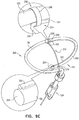
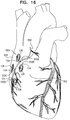
- a surgeon after delivering the tissue-coupling element through the wall of the heart, ascertains whether the tissue-coupling element overlies a coronary blood vessel, such as the right coronary artery (RCA). If the tissue-coupling element overlies the coronary blood vessel, the surgeon rotates the tissue anchor until the tissue-coupling element no longer overlies the coronary blood vessel. The surgeon then brings the tissue-coupling element into contact with an external surface of the heart, by applying tension to the anchor head in the heart chamber.
- a coronary blood vessel such as the right coronary artery (RCA).
- the off-centeredness of the tissue-coupling element thus allows the surgeon to select an anchoring site from a plurality of anchoring sites around an exit site of the anchor on the heart wall, without the need to relocate the exit site by removing the tissue-coupling element and again penetrating the deployment tool through the heart wall to redeliver the tissue-coupling element.
- the off-centeredness of the tissue-coupling element allows for the biasing of the tissue-coupling element away from the exit site, by rotating the tissue-coupling element to find a point of minimal impact on the cardiac circulation.
- the tissue-coupling element might inadvertently compress a blood vessel, which might result in cardiac complications including but not limited to angina, myocardial infarction, reduced blood flow, and/or a reduction in circulation efficiency in cardiac tissue. Removal of such an improperly positioned tissue-coupling element might be required, which might result in additional complications and injury to the patient.
- the shaft has a central longitudinal axis
- the head is coaxial with the central longitudinal axis
- the tissue-coupling element is shaped such that if the tissue-coupling element were to be projected onto a plane that is perpendicular to the central longitudinal axis, (i) at least 80% (e.g., at least 90%, such as at least 95%) of an area of a projection of the tissue-coupling element on the plane would fall within a first angle of 180 degrees in the plane having a vertex at the central longitudinal axis, and (ii) the area would partially overlap, at a distance of at least 3 mm from the vertex, both rays of a second angle of between 45 and 180 degrees in the plane having the vertex at the central longitudinal axis.
- a wire thereof when the tissue anchor is unconstrained by the deployment tool, a wire thereof (a) is shaped as an open loop (e.g., a three-dimensional open loop), such as a spiral (e.g., a three-dimensional spiral) around a center point, and (b) extends from a distal end of the shaft at a radially-outer end of the open loop, e.g., spiral.
- the tissue-coupling element is non-helical when the tissue anchor is unconstrained by the deployment tool.
- the tissue anchor further comprises a flexible elongate tension member, which is typically distinct from the wire of the tissue-coupling element, and which is fixed to a site on the open loop and crosses at least a portion of the open loop when the tissue anchor is unconstrained by the deployment tool.
- the flexible elongate tension member typically includes (a) a distal portion that is fixed to a site on the open loop (such as on an outermost turn of the open loop), (b) a proximal portion, which has a longitudinal segment that runs alongside at least a portion of the shaft, and (c) a crossing portion, which (i) is disposed between the distal and the proximal portions along the flexible elongate tension member, and (ii) crosses at least a portion of the open loop when the tissue anchor is unconstrained by the deployment tool.
- Tension is applied to the tissue-coupling element of the tissue anchor via the flexible elongate tension member. The applied tension is resisted by the outward force of the open loop.
- the applied tension compresses and stiffens the open loop.
- This arrangement of tension distribution may overcome any natural tendency of the open loop to straighten if tension were to be applied along the central longitudinal axis via the shaft, and thus may allow the application of a greater load to the open loop. It is noted that the maximum design stiffness of the open loop is constrained by the need for the open loop to be straightened for delivery in a shaft of the deployment tool.
- the head is shaped so as to define a passage in which the proximal portion of the flexible elongate tension member is slidably disposed.
- the flexible elongate tension member comprises a locking stopper, which is axially fixed to the proximal or the crossing portion of the flexible elongate tension member.
- the locking stopper and the passage are sized and shaped such that the size and shape of the passage prevent proximal movement of the locking stopper past the passage.
- the locking stopper limits the total load that can be applied to the open loop by the flexible elongate tension member, thereby reducing excessive, unnecessary strain on the open loop. Additional load (tension) that is applied by the flexible elongate tension member pulls on the entire anchor, and does not further increase the load applied across the open loop.
- the tissue anchor is configured to allow relative axial motion between the at least a portion of the shaft and the longitudinal segment of the proximal portion of the flexible elongate tension member when the tissue anchor is unconstrained by the deployment tool.
- Such axial motion allows tension to be applied to the flexible elongate tension member without also being applied to the shaft, and allows the open loop to be unwound and the flexible elongate tension member to be disposed alongside a portion of the flexible elongate tension member.
- the longitudinal segment of the proximal portion of the flexible elongate tension member is coupled in sliding communication with the at least a portion of the shaft when the tissue anchor is unconstrained by the deployment tool.
- the tissue anchor comprises one or more annular elements, which are disposed around the at least a portion of the shaft, and couple the flexible elongate tension member in the sliding communication with the at least a portion of the shaft when the tissue anchor is unconstrained by the deployment tool.
- the annular elements may comprise one or more collars, loops, or rings.
- a tissue anchor comprising the spiral and the flexible elongate tension member remained firmly implanted in tissue of the ventricular wall, without damaging the tissue, and without fracturing of the anchor under high loads.
- loads of up to 25 N could be safety applied. It was noted that the tension applied through the flexible elongate tension member was of a magnitude of three times that of the load that could be applied through the central longitudinal axis of the shaft.
- a tissue anchor system which comprises (a) a first off-center tissue anchor, such as described above, (b) a second tissue anchor, and (c) one or more tethers, which are configured to couple (i) the head of first tissue anchor to (ii) the second tissue anchor.
- the second tissue anchor comprises a helical tissue-coupling element.
- the second tissue anchor comprises a stent.
- the tissue anchor comprises the flexible elongate tension member, as described above
- the one or more tethers are fixed to the flexible elongate tension member. When tension is applied to the one or more tethers, the tension is transmitted to the flexible elongate tension member, rather than to the shaft via the head.
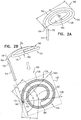
- the tissue-coupling element comprises three or more tines, such as four or more tines.
- the shaft has a central longitudinal axis
- the tines extend radially outward from the central longitudinal axis in respective directions that are fixed with respect to one another
- the tissue-coupling element is shaped such that if the tissue-coupling element were to be projected onto a plane that is perpendicular to the central longitudinal axis, at least 80% of an area of a projection of the tissue-coupling element on the plane would fall within an angle of 210 degrees in the plane having a vertex at the central longitudinal axis.
- the tissue-coupling element further comprises one or more membranes that are fixed to and extend between circumferentially-adjacent ones of the tines.
- the membranes and tines together might be considered to define a structure similar in some respect to a bat wing, or a partial umbrella.
- the membranes may help evenly distribute the force on the external surface of the heart applied by the tissue-coupling element.
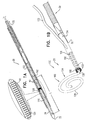
- Some embodiments of the present disclosure provide a tissue anchor 20 and a deployment tool 30, which is typically configured to deliver the tissue anchor through a wall of a heart of a subject, typically by advancing a sharp distal piercing tip 32 of the deployment tool through the wall.
- Figs. 1A-D are schematic illustrations of a tissue anchor 120 in several stages of deployment from deployment tool 30.
- Tissue anchor 120 is one implementation of tissue anchor 20, described above.
- Tissue anchor 120 comprises (a) a shaft 122, (b) a head 124 connected to a proximal portion 126 of shaft 122, and (c) a tissue-coupling element 128, which extends from a distal end 130 of shaft 122.
- shaft 122 and tissue-coupling element 128 are integral to one another; for example, shaft 122 and tissue-coupling element 128 may comprise a wire.
- one or more tethers 132 are provided, which are configured to be coupled to tissue anchor 120, such as to head 124 of tissue anchor 120; for example, one of the one or more tethers 132 may be fixed to head 124.
- Deployment tool 30 is configured to constrain tissue-coupling element 128 while delivering tissue-coupling element 128 through tissue.
- deployment tool 30 is configured to hold tissue-coupling element 128 in an elongated configuration, which may be straight (such as shown) or curvy (such as shown in Fig. 5A ).
- deployment tool 30 comprises a shaft 34 shaped so as to define a lumen, such as a hypodermic needle. The lumen is sized to hold tissue-coupling element 128 constrained therein, and, optionally, to hold other portions of tissue anchor 20 therein, such as shaft 122 and/or head 124.
- deployment tool 30 has a length of between 100 and 180 cm, and/or an inner diameter of between 2 and 6 mm.
- deployment tool 30 comprises a distal-most rigid portion, which typically has a length of 5 to 25 mm, and the remaining proximal portion of the deployment tool is flexible (but not extendable or compressible).
- the proximal portion is shaped so as to define one or more lateral slots, which provide flexibility to the proximal portion, while maintaining a backbone that prevents longitudinal compression and extension of the proximal portion.
- deployment tool 30 is advanced within a steerable catheter tube 40, as is known in the art, which may, for example, comprise a braided material.
- tissue anchor 20 is provided in sterile packaging, optionally pre-positioned in deployment tool 30.
- tissue anchor 120 (including tissue-coupling element 128, shaft 122, and head 124) fully constrained by deployment tool 30.
- tissue-coupling element 128 typically has an outer diameter of at least 0.3 mm, no more than 4 mm, and/or between 0.3 and 4 mm, such as at least 1 mm, no more than 3 mm, and/or between 1 and 3 mm.
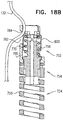
- Fig. 1B shows tissue-coupling element 128 released from deployment tool 30, while a portion of tissue anchor 120 is still constrained by deployment tool 30.
- Fig. 1C shows tissue anchor 120 entirely released from deployment tool 30.
- Fig. 1D shows tissue anchor 120 deployed against a wall 194 of a heart chamber, upon release from deployment tool 30.
- Tissue-coupling element 128 is disposed on a far side of wall 194, and head 124 is disposed on a near side of wall 194.
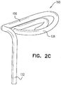
- FIGs. 2A-B and 2C are schematic illustrations of tissue-coupling element 128 and shaft 122.
- Figs. 2A-B provide two views of a first configuration tissue-coupling element 128 and shaft 122, when tissue anchor 120 is unconstrained by deployment tool 30, and
- Fig. 2C provides a view of a second configuration of tissue-coupling element 128 and shaft 122, when tissue anchor 120 is unconstrained by deployment tool 30.
- tissue anchor 120 is unconstrained by deployment tool 30, such as shown in Figs. 1B-C and 2A-C :
- a "central longitudinal axis" of an elongate structure is the set of all centroids of transverse cross-sectional sections of the structure along the structure.
- the cross-sectional sections are locally perpendicular to the central longitudinal axis, which runs along the structure. (If the structure is circular in cross-section, the centroids correspond with the centers of the circular cross-sectional sections.)
- Tissue-coupling element 128 is configured to have a predetermined shape when unconstrained by deployment tool 30.
- the tissue-coupling element may comprise a shape-memory material, such as a shape-memory alloy, e.g., Nitinol.
- tissue-coupling element 128 automatically transitions to the predetermined shape when released from being constrained by deployment tool 30 to being unconstrained by deployment tool 30.
- central longitudinal axis 134 is straight when tissue anchor 120 is unconstrained by deployment tool 30, such as shown in Figs. 1B-C and 2A-C .
- shaft 122 is flexible.
- tissue-coupling element 128 i.e., the surface defined by tissue-coupling element 128 that is configured to touch the external surface of the heart
- tissue-coupling element 128 is concave when tissue anchor 120 is unconstrained by deployment tool 30 (in other words, tissue-coupling element 128 is concave when viewed from proximal portion 126 of shaft 122).
- tissue-coupling element 128 is concave when viewed from proximal portion 126 of shaft 122).
- tissue-coupling element 128 is concave when viewed from proximal portion 126 of shaft 122).
- Such a concave shape may approximate the natural convex shape of an external surface of the wall of the heart.
- tissue-coupling element 128 is convex, when tissue anchor 120 is unconstrained by deployment tool 30 before being pulled against the external surface of the heart (in other words, tissue-coupling element 128 is convex when viewed from proximal portion 126 of shaft 122).
- tissue-coupling element 128 is convex when viewed from proximal portion 126 of shaft 122).
- Such a convex shape may be employed such that the radially internal section of the coil closest to a center point 162 of tissue-coupling element 128 contacts the tissue first, and gradually, as tension is applied, the full tissue-coupling element comes into contact with the external surface of the heart.
- the proximally-facing surface defined by the tissue-coupling element may assume a concave shape conforming to the convex shape of the external surface of the heart. This arrangement may lead to a more even distribution of load on the heart tissue and result in a more durable loading configuration on the tissue.
- the proximally-facing surface defined by tissue-coupling element 128 is generally flat, when tissue anchor 120 is unconstrained by deployment tool 30 (configuration not shown).
- the proximally-facing surface defined by the tissue-coupling element may assume a concave shape conforming to the convex shape of the external surface of the heart.
- tissue anchor 120 is unconstrained by deployment tool 30:
- a ratio of the greatest longitudinal dimension D2 and greatest lateral dimension D3 is between 1:2 and 1:18, such as between 1:5 and 1:10, e.g., 1:7 when tissue anchor 120 is unconstrained by deployment tool 30.
- tissue-coupling element 128 has a length L of at least 5 mm (e.g., at least 10 mm), no more than 100 mm (e.g., no more than 60 mm), and/or between 5 and 100 mm (e.g., between 10 and 60 mm) when constrained into a straight configuration, such as shown in Fig. 1A .
- tissue-coupling element 128 comprises a wire 150.
- a cross-sectional area of wire 150 is at least 0.09 mm2 (such as at least 0.18 mm2), no more than 3 mm2 (e.g., no more than 2.9 mm2), and/or between 0.09 mm2 (such as 0.18 mm2) and 3 mm2 (e.g., 2.9 mm2).
- wire 150 has a circular cross-section, and a diameter of wire 150 is at least 0.18 mm, no more than 2 mm, and/or between 0.18 and 2 mm.
- a distal end 152 of wire 150 does not define a sharp distal tip; for example, the distal end may be blunt.
- wire 150 comprises metal, such as Nitinol.
- wire 150 comprises one or more radiopaque markers.
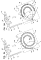
- wire 150 (a) is shaped as an open loop 154 having more than one turn, such that a first complete turn of open loop 154 at least partially overlaps (i.e., runs alongside, above, and/or below) a second at-least-partial turn of open loop 154.
- the first complete turn and the second at-least-partial turn radially coincide, i.e., are at a same distance as each other from a center point (configuration not shown).
- an outermost turn of open loop 154 at-least-partial ly overlaps (i.e., runs alongside, above, and/or below) a second-to-outermost turn of open loop 154 (for example, an outermost turn 214 and a second-to-outermost turn 216 of open loop 154 are labeled in Fig. 5D ).
- a second-to-outermost turn of open loop 154 for example, an outermost turn 214 and a second-to-outermost turn 216 of open loop 154 are labeled in Fig. 5D ).
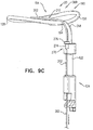
- the second-to-outermost turn of open loop 154 may be a partial turn, such as shown in Figs. 9A-B , 9E , 9F , and 9I .)
- open loop 154 For applications in which open loop 154 includes an outermost turn and a second-to-outermost turn, open loop 154 has a radially-outer end 164 and a radially-inner end 264, which typically do not touch each other at least when tissue anchor 120 is unconstrained by deployment tool 30. For applications in which the first complete turn and the second at-least-partial turn radially coincide, the two opposite ends of the open loop typically do not touch each other at least when tissue anchor 120 is unconstrained by deployment tool 30. Open loop 154 is defined by an elongate path of wire 150 that winds more than one turn around center point 162 without forming a closed loop.
- the elongate path may include one or more curved segments and/or one or more straight segments, such as described hereinbelow with reference to Fig. 9I .
- the path may fall in two dimensions, or may fall in three dimensions, in which case the open loop is a three-dimensional open loop, the elongate path of which winds around a center axis while moving parallel to the axis, without forming a closed loop.
- open loop 154 extends from distal end 130 of shaft 122 at radially-outer end 164 of open loop 154.
- wire 150 intersects center point 162 when tissue anchor 120 is unconstrained by deployment tool 30 (configuration not shown), while for other applications, wire 150 does not intersect center point 162 when tissue anchor 120 is unconstrained by deployment tool 30 (as shown).
- open loop 154 has more than one turn and less than two turns.
- open loop 154 may have at least 1.5 turns and no more than two turns, or, as shown in Figs.
- open loop 154 may have more than one turn and less than 1.5 turns, such as more than one turn, e.g., more than 1.01 turns (363.6 degrees), such as more than 1.02 turns (367.2 degrees), and/or less than 1.25 turns (450 degrees).
- open loop 154 may have at least two turns, such as at least two turns and less than 2.5 turns (as shown in Figs. 5B-D and 6A-B ), or more than 2.5 turns, e.g., more than three turns (configurations not shown).
- wire 150 of open loop 154 is shaped as a spiral 160 (e.g., a three-dimensional spiral) around center point 162.
- wire 150 of spiral 160 extends from distal end 130 of shaft 122 at radially-outer end 164 of spiral 160.
- wire 150 of spiral 160 intersects center point 162 when tissue anchor 120 is unconstrained by deployment tool 30 (configuration not shown), while for other applications, wire 150 of spiral 160 does not intersect center point 162 when tissue anchor 120 is unconstrained by deployment tool 30 (as shown).
- spiral 160 is generally circular when tissue anchor 120 is unconstrained by deployment tool 30, such as shown in Figs. 1B , 2A-C , and 3A-B , while for other applications, spiral 160 is an elliptical spiral when the tissue anchor is unconstrained by deployment tool 30, such as shown in Figs. 5B-D , 6A-B , 7A , 8A , 9A-B , and 9E-G .
- center point 162 is the centroid of projection 139 of tissue-coupling element 128 on plane 136.
- tissue-coupling element 128 is non-helical when tissue anchor 120 is unconstrained by deployment tool 30.
- spiral 160 has more than one turn and less than two turns.
- spiral 160 may have at least 1.5 turns and no more than two turns, or, as shown in Figs. 9A-B and 9E-G , spiral 160 may have more than one turn and less than 1.5 turns, such as more than one turn and less than 1.25 turns.
- spiral 160 may have more than one turn and less than 1.5 turns, such as more than one turn and less than 1.25 turns.
- spiral 160 may have at least two turns, such as at least two turns and less than 2.5 turns (as shown in Figs. 5B-D and 6A-B ), or more than 2.5 turns, e.g., more than three turns (configurations not shown).
- the open loop (e.g., the spiral) has greatest lateral dimension D3, measured perpendicular to central longitudinal axis 134, and a distance D4 between (a) radially-outer end 164 of open loop 154 (e.g., spiral 160) and (b) a radially-inner-most point 166 of open loop 154 (e.g., spiral 160), measured perpendicular to central longitudinal axis 134, is equal to at least 30% of the greatest lateral dimension D3.
- a distance between radially-innermost point 166 and a closest point thereto on an outermost turn of open loop 154, measured perpendicular to central longitudinal axis 134 is equal to at least 30% of the greatest lateral dimension D3.
- a distance between radially-innermost point 166 and a closest point thereto on an outermost turn of open loop 154, measured perpendicular to central longitudinal axis 134 equals less than 10% of the greatest lateral dimension D3.
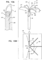
- FIGs. 3A-B are schematic illustrations of tissue-coupling element 128 and shaft 122.
- at least 80%, such as at least 90%, e.g., at least 95%, of area 138 of projection 139 of tissue-coupling element 128 on plane 136 would fall within a third angle ⁇ (gamma) of 150 degrees in plane 136 having vertex 140 at central longitudinal axis 134, if tissue-coupling element 128 were to be projected onto plane 136.
- ⁇ gamma
- an outer portion 168 of area 138 of projection 139 of tissue-coupling element 128 on plane 136 consists of all points of area 138 at least a distance D from vertex 140; for example, the distance D may be 2 mm, such as 3 mm, e.g., 4 mm.
- Outer portion 168 would fall within all angular positions of a fourth angle ⁇ (delta) of 90 degrees in plane 136 having vertex 140 at central longitudinal axis 134, which outer portion 168, if tissue-coupling element 128 were to be projected onto plane 136.
- fourth angle ⁇ delta
- Outer portion 168 may additionally fall within angular positions outside of fourth angle ⁇ (delta), such as shown in Fig. 3B .)
- tissue anchor 120 is a first tissue anchor 182A of tissue anchor system 180, which further comprises (a) a second tissue anchor 182B, which is separate and distinct first tissue anchor 182A, and (b) the one or more tethers 132, which are configured to couple (i) head 124 of first tissue anchor 182A to (ii) second tissue anchor 182B.
- tissue anchor 120 is fixed to (a) head 124 of first tissue anchor 182A and (b) second tissue anchor 182B.
- second tissue anchor 182B comprises a helical tissue-coupling element 184.
- second tissue anchor 182B may implement techniques described in PCT Publication WO 2014/108903 .
- second tissue anchor 182B comprises a stent 186.
- second tissue anchor 182B may implement techniques described in one or more of the following applications: US Patent Application Publication 2011/0184510 , US Patent Application Publication 2012/0035712 , US Patent Application Publication 2013/0018459 , US Patent Application Publication 2013/0046380 , and/or PCT Publication WO 2014/141239 .
- shaft 122 comprises a sealing element 190, which is configured to form a blood-tight seal between a portion of shaft 122 inside the heart chamber and wall 194 of the heart.
- sealing element 190 is annular, and snugly surrounds shaft 122.
- shaft 122 further comprises a spring 192, which is disposed proximal to sealing element 190, and is configured to apply a distal force to sealing element 190, in order to push sealing element against wall 194 of the heart chamber, in order to form a tight seal, such as shown in Fig. 1D .
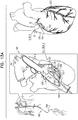
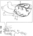
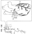
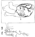
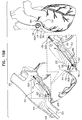
- tissue anchor 120 is implanted using techniques described hereinbelow with reference to Figs. 13A-D , 15A-C , and/or 16, optionally in combination with techniques described in one or more of the patents and patent application publications identified hereinbelow by reference, mutatis mutandis.
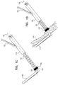
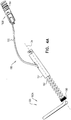
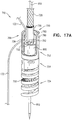
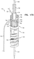
- FIGs. 5A-D are schematic illustrations of a tissue anchor 200 in several stages of deployment from deployment tool 30, in accordance with an application of the present invention.
- Tissue anchor 200 is one implementation of tissue anchor 20, described above.
- tissue anchor 200 is generally similar to tissue anchor 120, described hereinabove with reference to Figs. 1A-4B , and may implement any of the features thereof, mutatis mutandis.
- tissue-coupling element 128 typically comprises wire 150.
- shaft 122 and tissue-coupling element 128 are integral to one another; for example, shaft 122 and tissue-coupling element 128 may both comprise wire 150, as shown.
- Deployment tool 30 is configured to constrain tissue-coupling element 128 while delivering tissue-coupling element 128 through tissue.
- deployment tool 30 is configured to hold tissue-coupling element 128 in an elongated, unwound configuration, which may be curvy (such as shown in Fig. 5A ) or straight (such as shown in Fig. 1A ).
- tissue-coupling element 128 is constrained by the deployment tool, a longitudinal portion of flexible elongate tension member 202, described hereinbelow, runs alongside a portion of wire 150.
- deployment tool 30 comprises a removable driver 201, which comprises a driver head 203 and at least one shaft 205 that is coupled to the driver head.
- Driver head 203 is removably coupled to anchor head 124 during penetration of tissue-coupling element 128 through tissue, as described hereinbelow.
- the at least one shaft 205 is configured to controllably detach the driver head from the anchor head.
- a deployment needle may run through a channel of the at least one shaft; pulling on the needle detaches the driver head from the anchor head.
- wire 150 is shaped as open loop 154 (e.g., a three-dimensional open loop), such as spiral 160 (e.g., a three-dimensional spiral) around center point 162 (labeled in Figs. 2B and 5D ).
- open loop 154 e.g., a three-dimensional open loop
- spiral 160 e.g., a three-dimensional spiral
- center point 162 labeleled in Figs. 2B and 5D
- wire 150 extends from distal end 130 of shaft 122 at radially-outer end 164 of open loop 154 (e.g., spiral 160) (labeled in Figs. 5C and 5D ), when tissue anchor 200 is unconstrained by deployment tool 30.
- wire 150 intersects center point 162 when tissue anchor 200 is unconstrained by deployment tool 30 (configuration not shown), while for other applications, wire 150 does not intersect center point 162 when tissue anchor 200 is unconstrained by deployment tool 30 (as shown).
- wire 150 extends from distal end 130 of shaft 122 at radially-inner end 264 of open loop 154 (e.g., spiral 160).
- open loop 154 e.g., spiral 160
- tissue-coupling element 128 has one or more of the characteristics described hereinabove with reference to Figs. 3A-B .
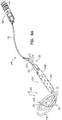
- Tissue anchor 200 further comprises a flexible elongate tension member 202, which includes:
- flexible elongate tension member 202 is fixed to wire 150 of tissue-coupling element 128, flexible elongate tension member 202 is typically distinct from wire 150.
- flexible elongate tension member 202 and wire 150 are not two longitudinal portions of a single continuous wire, i.e., are not longitudinally contiguous with each other.
- Tension is applied to tissue-coupling element 128 of tissue anchor 200 via flexible elongate tension member 202.
- the applied tension is resisted by the outward force of open loop 154 (e.g., spiral 160).
- the applied tension at least partially compresses and stiffens open loop 154 (e.g., spiral 160).
- This arrangement of tension distribution may overcome any natural tendency of open loop 154 (e.g., spiral 160) to straighten (i.e., unwind) if tension were to be applied along central longitudinal axis 134 via shaft 122, and thus may allow the application of a greater load to open loop 154 (e.g., spiral 160).
- this stiffening technique allows open loop 154 (e.g., spiral 160) to be manufactured less stiff than it otherwise would need to be, which facilitates straightening and delivering the tissue anchor, and subsequent stiffening in situ.
- flexible elongate tension member 202 is not taut across the at least a portion of open loop 154 (e.g., spiral 160).
- flexible elongate tension member 202 may arc distally, such as can best be seen in Fig. 5C .
- tissue anchor 200 is configured to allow relative axial motion between the at least a portion 210 of shaft 122 and longitudinal segment 209 of proximal portion 208 of flexible elongate tension member 202 when tissue anchor 200 is unconstrained by deployment tool 30 (as flexible elongate tension member 202 is tensioned and pulls on tissue-coupling element 128, tissue anchor 200 becomes progressively more constrained by flexible elongate tension member 202; the relative axial motion nevertheless remains possible).
- longitudinal segment 209 of proximal portion 208 of flexible elongate tension member 202 is axially moveable with respect to the at least a portion 210 of shaft 122 when tissue anchor 200 is unconstrained by deployment tool 30.
- Such axial motion allows tension to be applied to flexible elongate tension member 202 without also being applied to shaft 122, and allows open loop 154 (e.g., spiral 160) to be unwound and flexible elongate tension member 202 to be disposed alongside a portion of flexible elongate tension member 202, as shown in Fig. 5A (in which deployment tool 30 constrains both constrain tissue-coupling element 128 and flexible elongate tension member 202).
- longitudinal segment 209 of proximal portion 208 of flexible elongate tension member 202 is coupled in sliding communication with the at least a portion 210 of shaft 122, when tissue anchor 200 is unconstrained by deployment tool 30.
- tissue anchor 200 comprises one or more annular elements, which are disposed around the at least a portion of shaft 122, and couple flexible elongate tension member 202 in the sliding communication with the at least a portion 210 of shaft 122, when tissue anchor 200 is unconstrained by deployment tool 30.
- the annular elements may comprise one or more collars 244, described hereinbelow, loops, or rings.
- flexible elongate tension member 202 is not fixed to any portion of open loop 154 (e.g., spiral 160) beyond 2 mm from site 206 on open loop 154 (e.g., spiral 160), measured when tissue anchor 200 is unconstrained by deployment tool 30.
- flexible elongate tension member 202 is not fixed to any portion of open loop 154 (e.g., spiral 160) beyond a distance from site 206 on open loop 154 (e.g., spiral 160), which distance equals 30% of greatest lateral dimension D3 of open loop 154 (e.g., spiral 160) of tissue-coupling element 128, measured perpendicular to central longitudinal axis 134 (labeled in Fig.
- flexible elongate tension member 202 is fixed to open loop 154 (e.g., spiral 160) only at site 206 on open loop 154 (e.g., spiral 160).
- open loop 154 e.g., spiral 160
- a distal portion of flexible elongate tension member 202 beyond site 206 is fixed to open loop 154 (e.g., spiral 160), such as described hereinbelow with reference to Figs. 9E and 9F .
- the at least a portion of open loop 154 (e.g., spiral 160) crossed by crossing portion 212 has a length that equals at least 33% of greatest lateral dimension D3 of open loop 154 (e.g., spiral 160) of tissue-coupling element 128, measured perpendicular to central longitudinal axis 134 (labeled in Fig. 2A ), e.g., at least 50% of greatest lateral dimension D3, such as at least 75% of greatest lateral dimension D3, e.g., at least 90% of greatest lateral dimension D3.
- site 206 is on an outermost turn 214 of open loop 154 (e.g., spiral 160) (labeled in Fig. 5D ), when tissue anchor 200 is unconstrained by deployment tool 30.
- site 206 is on a second-to-outermost turn 216 of open loop 154 (e.g., spiral 160) (labeled in Fig. 5D ), when tissue anchor 200 is unconstrained by deployment tool 30 (configuration not shown).
- a radius of flexible elongate tension member 202 is less than a radius of wire 150, such as less than 50% of the radius of wire 150.
- a cross-sectional area of wire 150 is at least 0.09 mm2 (such as at least 0.18 mm2), no more than 3 mm2 (e.g., no more than 2.9 mm2), and/or between 0.09 mm2 (such as 0.18 mm2) and 3 mm2 (e.g., 2.9 mm2).
- flexible elongate tension member 202 comprises metal, such as a metal alloy, e.g., Nitinol.
- flexible elongate tension member 202 comprises radiopaque sections or is radiopaque, to enable observation of the relative movement when tensioning.
- site 206 on open loop 154 is a first site 206 on open loop 154 (e.g., spiral 160), and, when tissue anchor 200 is unconstrained by deployment tool 30 and flexible elongate tension member 202 is tensioned straight, (a) wire 150 extends from distal end 130 of shaft 122 at a second site 218 on open loop 154 (e.g., spiral 160), and (b) if tissue-coupling element 128 and flexible elongate tension member 202 were to be projected onto plane 136 that is perpendicular to central longitudinal axis 134, an angle ⁇ (theta) between the first and the second sites, having a vertex 242 at center point 162, would be between 130 and 180 degrees, such as between 150 and 180 degrees, e.g., between 170 and 180 degrees (labeled in Fig. 5D ).
- second site 218 is at radially-outer end 164 of open loop 154 (e.g.
- an angle ⁇ (phi) between (a) flexible elongate tension member 202 and (b) a tangent 250 to open loop 154 (e.g., spiral 160) at site 206 would be between 45 and 90 degrees, such as between 70 and 90 degrees, e.g., 90 degrees.
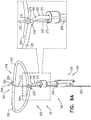
- shaft 122 comprises sealing element 190.
- sealing element 190 one or more collars 244 disposed around shaft 122, and, typically, a sleeve 246 that couples the collars 244 together.
- Sleeve 246 defines a lumen having proximal and distal ends.
- the flexible elongate tension member 202 slidingly passes through the lumen and its ends.
- sealing element 190 is typically sized and shaped to be inserted into the incision through the heart wall, and to provide a blood-tight seal.
- sleeve 246 promotes hemostasis.
- filament or fiber is provided within sleeve 246 to promote hemostasis.
- collars 244 comprise a distal guide collar 244A and a proximal driver collar 244B, which optionally is a component of or serves as head 124.
- a proximal end of shaft 122 is disposed within proximal driver collar 244B, as shown.
- one or more of collars 244 are radiopaque or comprise a radiopaque marker.
- sleeve 246 may comprise Dacron, and/or may be coated and/or woven to facilitate clotting.
- sealing element 190 has the configuration described hereinabove with reference to Figs. 1A-D and 4A-B , or the configuration described hereinbelow with reference to Figs. 9A-F or Fig. 9G .
- a proximally-facing surface defined by tissue-coupling element 128 is convex when tissue anchor 200 is unconstrained by deployment tool 30, such as shown in Figs. 2C and 5B-C .
- a proximally-facing surface defined by tissue-coupling element 128 is concave when tissue anchor 200 is unconstrained by deployment tool 30, such as shown in Fig. 2B .
- one or more tethers 132 are provided, which are configured to be coupled to tissue anchor 200.
- the one or more tethers 132 are fixed to flexible elongate tension member 202, typically to proximal portion 208 of the tension member, such as at or near (e.g., within 1 cm of) a proximal end of proximal portion 208.
- head 124 of tissue anchor 120 is coupled to the one or more tethers.
- the one or more tethers are (a) fixed to the second tissue anchor and (b) not fixed to shaft 122 of first tissue anchor 200.
- a radially-inner end 264 of open loop 154 (e.g., spiral 160) is bent proximally, such as can be best seen in Fig. 5C . Because of the bend, radially-inner end 264 may help tissue-coupling element 128 resist rotation and uncoiling.
- tissue anchor 200 is a first tissue anchor 182A of tissue anchor system 248, which further comprises (a) a second tissue anchor 182B, which is separate and distinct first tissue anchor 182A, and (b) the one or more tethers 132, which are configured to couple (i) flexible elongate tension member 202 of first tissue anchor 182A to (ii) second tissue anchor 182B.
- tissue anchor 200 is a first tissue anchor 182A of tissue anchor system 248, which further comprises (a) a second tissue anchor 182B, which is separate and distinct first tissue anchor 182A, and (b) the one or more tethers 132, which are configured to couple (i) flexible elongate tension member 202 of first tissue anchor 182A to (ii) second tissue anchor 182B.
- one of the one or more tethers 132 is fixed to (a) flexible elongate tension member 202 of first tissue anchor 182A to (b) second tissue anchor 182B.
- second tissue anchor 182B comprises helical tissue-coupling element 184.
- second tissue anchor 182B may implement techniques described in PCT Publication WO 2014/108903 .
- second tissue anchor 182B comprises stent 186.
- second tissue anchor 182B may implement techniques described in one or more of the following applications: US Patent Application Publication 2011/0184510 , US Patent Application Publication 2012/0035712 , US Patent Application Publication 2013/0018459 , US Patent Application Publication 2013/0046380 , PCT Publication WO 2014/141239 , and/or the patents and patent application publications identified hereinbelow by reference.
- Figs. 7A-B are schematic illustrations of open loop 154 (e.g., spiral 160) of tissue anchor 200 unconstrained by deployment tool 30 and under tension, respectively, in accordance with an application of the present invention.
- tissue anchor 200 and open loop 154 (e.g., spiral 160) thereof) is unconstrained by deployment tool 30.
- open loop 154 e.g., spiral 160
- flexible elongate tension member 202 After tension is applied to flexible elongate tension member 202, flexible elongate tension member 202 becomes more narrow in the direction of flexible elongate tension member 202, such that open loop 154 (e.g., spiral 160) has a second outer dimension D6, measured in a direction parallel to flexible elongate tension member 202, which is less than first outer dimension D5, e.g., no more than 90% of D5, such as no more than 80% of D5, e.g., no more than 70% of D5, no more than 50% of D5, or no more than 20% of D5.
- first outer dimension D5 e.g., no more than 90% of D5
- no more than 80% of D5 e.g., no more than 70% of D5, no more than 50% of D5, or no more than 20% of D5.
- the force applied to flexible elongate tension member 202 to achieve this reduction is between 2 and 50 N, such as between 5 and 20 N, e.g., 5 N, 7 N, 10 N, 20 N, or 30 N.
- the amount of force is dependent on the radius of wire 150, and may increase as a power of the radius, such as a third or fourth power of the radius.
- a smallest radius of wire 150 is chosen that is able to withstand between 5 and 20 N of force.
- tissue anchor 258 is one implementation of tissue anchor 20, described above.
- tissue anchor 258 is generally similar to tissue anchor 200, described hereinabove with reference to Figs. 5A-7B , and may implement any of the features thereof, mutatis mutandis.
- tissue anchor 258 may implement any of the features of tissue anchor 120, described hereinabove with reference to Figs. 1A-4B , mutatis mutandis.
- Tissue-coupling element 128 of tissue anchor 258 comprises wire 150, which is shaped as an open loop 256, e.g., a spiral 260.
- Wire 150 extends from distal end 130 of shaft 122 at a radially-inner end 264 of open loop 256 (e.g., spiral 260), when tissue anchor 220 is unconstrained by deployment tool 30.
- This is unlike the typical configurations of open loop 154 (e.g., spiral 160), described hereinabove, in which wire 150 extends from distal end 130 of shaft 122 at radially-outer end 164 of open loop 154 (e.g., spiral 160).
- radially-inner end 264 of open loop 256 (e.g., spiral 260) is typically disposed within 15 mm of center point 162, such as coinciding with center point 162.
- tissue anchor 258 comprises exactly one flexible elongate tension member 202, which includes:
- site 206 is on outermost turn 214 of open loop 256 (e.g., spiral 260), when tissue anchor 258 is unconstrained by deployment tool 30.
- Flexible elongate tension member 202 may implement any of the features described hereinabove with reference to Figs. 5A-7B , mutatis mutandis.
- tissue anchor 258 comprises two flexible elongate tension members 202A and 202B, which include:
- sites 206A and 206B are on outermost turn 214 of open loop 256 (e.g., spiral 260), when tissue anchor 258 is unconstrained by deployment tool 30.
- Flexible elongate tension members 202A and 202B may implement any of the features described hereinabove with reference to Figs. 5A-7B , mutatis mutandis.
- tissue anchor 300 is one implementation of tissue anchor 20, described above.
- tissue anchor 300 is generally similar to tissue anchor 200, described hereinabove with reference to Figs. 5A-D , and may implement any of the features thereof, mutatis 5 mutandis.
- tissue anchor 300 is implemented using the configuration of Figs. 6A or 6B , mutatis mutandis.
- wire 150 is shaped as open loop 154 (e.g., a three-dimensional open loop) around center point 162 (labeled in Figs. 2B and 5D ), and, optionally, as spiral 160 (e.g., a three-dimensional spiral) around center point 162 (labeled in Figs. 2B and 5D ).
- open loop 154 e.g., a three-dimensional open loop
- spiral 160 e.g., a three-dimensional spiral
- wire 150 extends from distal end 130 of shaft 122 at radially-outer end 164 of open loop 154 (and, optionally, spiral 160) (labeled in Fig.
- tissue-coupling element 128 has one or more of the characteristics described hereinabove with reference to Figs. 3A-B .
- the proximally-facing surface defined by tissue-coupling element 128 is generally flat, when tissue anchor 300 is unconstrained by deployment tool 30 (configuration not shown).
- the proximally-facing surface defined by the tissue-coupling element may assume a concave shape conforming to the convex shape of the external surface of the heart.
- tissue anchor 300 further comprises a flexible elongate tension member 202, which includes:
- flexible elongate tension member 202 is fixed to wire 150 of tissue-coupling element 128, flexible elongate tension member 202 is typically distinct from wire 150.
- flexible elongate tension member 202 and wire 150 are not two longitudinal portions of a single continuous wire, i.e., are not longitudinally contiguous with each other.
- Tension is applied to tissue-coupling element 128 of tissue anchor 300 via flexible elongate tension member 202.
- the applied tension is resisted by the outward force of open loop 154.
- the applied tension at least partially compresses and stiffens open loop 154.
- This arrangement of tension distribution may overcome any natural tendency of open loop 154 to straighten (i.e., unwind) if tension were to be applied along central longitudinal axis 134 via shaft 122, and thus may allow the application of a greater load to open loop 154.
- flexible elongate tension member 202 is not taut across the at least a portion of open loop 154.
- flexible elongate tension member 202 may arc distally, such as can best be seen in Fig. 9A .
- tissue anchor 300 is configured to allow relative axial motion between the at least a portion 210 of shaft 122 and longitudinal segment 209 of proximal portion 208 of flexible elongate tension member 202 when tissue anchor 300 is unconstrained by deployment tool 30.
- Such axial motion allows tension to be applied to flexible elongate tension member 202 without also being applied to shaft 122, and allows open loop 154 to be unwound and flexible elongate tension member 202 to be disposed alongside a portion of flexible elongate tension member 202, as shown in Fig. 9A .
- tissue anchor 300 comprises one or more annular elements, which are disposed around the at least a portion of shaft 122, and couple flexible elongate tension member 202 in the sliding communication with the at least a portion 210 of shaft 122, when tissue anchor 300 is unconstrained by deployment tool 30.
- the annular elements may comprise one or more collars, loops, or rings.
- Shaft 122 (e.g., the collars) is shaped such that flexible elongate tension member 202 runs generally parallel to central longitudinal axis 134 of shaft 122.
- site 206 is on an outermost turn of open loop 154, when tissue anchor 300 is unconstrained by deployment tool 30.
- site 206 is on a second-to-outermost turn of open loop 154, when tissue anchor 300 is unconstrained by deployment tool 30 (configuration not shown).
- a radius of flexible elongate tension member 202 is less than a radius of wire 150, such as less than 50% of the radius of wire 150.
- Flexible elongate tension member 202 and/or wire 150 may have any of the characteristics described hereinabove with reference to Figs. 2A-C , 3A-B , and/or 5A-D , including dimensions and relative arrangement with respect to each other.
- one or more tethers 132 are provided, which are configured to be coupled to tissue anchor 300.
- the one or more tethers 132 are fixed to flexible elongate tension member 202, typically to proximal portion 208 of the tension member, such as at or near (e.g., within 1 cm of) a proximal end of proximal portion 208.
- the tension is transmitted to flexible elongate tension member 202, rather than to shaft 122 via head 124.
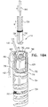
- head 124 is shaped so as to define a passage 272 in which proximal portion 208 of flexible elongate tension member 202 is slidably disposed.
- Flexible elongate tension member 202 comprises a locking stopper 270, which is axially fixed to proximal portion 208 or crossing portion 212 of flexible elongate tension member 202.
- Locking stopper 270 and passage 272 are sized and shaped such that the size and shape of passage 272 prevent proximal movement of locking stopper 270 past passage 272.
- locking stopper 270 engages passage 272 (as shown).
- passage 272 is a channel through a portion of head 124 (such as through one or more collars of head 124) (as shown), while for other applications, passage 272 is a groove (e.g., a U-shaped groove) (configuration not shown).
- locking stopper 270 is shaped so as to define a base 274 and a flange 276. The flange is too large to pass through passage 272, while base 274 may or may not be too large to enter the passage.
- locking stopper 270 is manufactured as a separate element that is fixed to flexible elongate tension member 202, such as by crimping, welding, or soldering.
- locking stopper 270 is integral to flexible elongate tension member 202.
- passage 272 extends to a distal end of head 124 (as shown), while for other applications, passage 272 is disposed more proximally in head 124, such as near a proximal end of head 124 (configuration not shown).
- locking stopper 270 is axially fixed to proximal portion 208 or crossing portion 212 of flexible elongate tension member 202 at a distance of at least 7 mm, no more than 22 mm, and/or between 7 and 22 mm from site 206 on the open loop, measured along flexible elongate tension member 202 (i.e., measured along the curvature of flexible elongate tension member 202 if it is curved, such as shown in Figs. 9A-B ).
- locking stopper 270 would be a distance of at least 7 mm, no more than 12 mm, and/or between 7 and 12 mm (e.g., 10 mm) from passage 272.
- tissue anchor 300 is unconstrained by deployment tool 30 (and flexible elongate tension member 202 is curved, such as shown in Figs.
- locking stopper 270 is disposed at a distance of at least 7 mm, no more than 12 mm, and/or between 7 and 12 mm (e.g., 10 mm) from passage 272.
- locking stopper 270 moves between 5 and 8 mm toward passage 272, such that locking stopper 270 is disposed at a distance of at least 2 mm, no more than 5 mm, and/or between 2 and 5 mm (e.g., 10 mm) from passage 272.
- tension is applied to tissue-coupling element 128 of tissue anchor 200 via flexible elongate tension member 202.
- the applied tension is resisted by the outward force of open loop 154.
- the applied tension at least partially compresses and stiffens open loop 154.
- This arrangement of tension distribution may overcome any natural tendency of open loop 154 to straighten (i.e., unwind) if tension were to be applied along central longitudinal axis 134 via shaft 122, and thus may allow the application of a greater load to open loop 154.
- the tension applied to tissue-coupling element 128 thus locks open loop 154 into a desired shape.
- Locking stopper 270 limits the total load that can be applied to open loop 154 by flexible elongate tension member 202, thereby reducing excessive, unnecessary strain on open loop 154.
- the first 1.5 to 5 N of force applied to flexible elongate tension member 202 may sufficiently deform open loop 154 and engage locking stopper 270.
- Additional load (tension) that is applied by flexible elongate tension member 202 pulls on the entire anchor 300, and does not further increase the load applied across open loop 154 to site 206, and thus does not further compress the open loop.
- tension may be applied to pull anchor 300 closer to another tissue anchor, in order to facilitate repair of an atrioventricular valve of the subject, such as tricuspid valve 504.
- tissue-coupling element in order to not generate too much outward force inside a delivery tube, which might make axial movement of the tissue-coupling element in the delivery tube difficult or impossible.
- the tissue-coupling element is tensioned upon delivery, thereby changing its shape and providing a strong tissue-coupling element that cannot unwind easily, and thus remains coupled to the tissue.
- minimizing the load on attachment site 206 provides a mechanical advantage that increases the durability of the device under higher loads.
- open loop 154 may have more than one turn and less than 1.5 turns, such as more than one turn, e.g., more than 1.01 turns (363.6 degrees), such as more than 1.02 turns (367.2 degrees), and/or less than 1.25 turns (450 degrees) (one turn equals 360 degrees).
- Figs. 9E and 9F are schematic illustrations of alternative ways to fix flexible elongate tension member 202 to site 206 of open loop 154, in accordance with respective applications of the present invention. These techniques may be used for tissue anchor 200 or tissue anchor 300.
- distal portion 204 of flexible elongate tension member 202 is fixed to site 206 on open loop 154 by crimping a crimping element 288 around wire 150.
- a distal portion of flexible elongate tension member 202 beyond site 206 is fixed (e.g., by welding or soldering) to open loop 154, such as near radially-inner end 264 of open loop 154.
- the portion of flexible elongate tension member 202 between site 206 and radially-inner end 264 may be attached to wire 150, or may be held near wire 150, such as by a sleeve, as described with reference to Fig. 9F .
- site 206 is the site on open loop 154 at which flexible elongate tension member 202 makes functional contact with the loop for applying tension across the loop, rather than other sites along wire 150 to which flexible elongate tension member 202 may also be attached.
- Fig. 9F may be used in combination with the configuration shown in Fig. 9E , or separately.
- open loop 154 is covered with a sleeve 280, which may comprise a woven material, comprising, for example, polyester.
- a distal portion of flexible elongate tension member 202 beyond site 206 is fixed (e.g., by welding or soldering) to open loop 154, such as near radially-inner end 264 of open loop 154 (this area of open loop 154 may facilitate attachment because this area is straighter than other portions of the open loop).
- Flexible elongate tension member 202 penetrates and exits sleeve 280 at site 206, such as by passing between the fibers of sleeve 280, or through an opening made in sleeve 280, which opening is optionally reinforced.
- Distal portion 204 of flexible elongate tension member 202 is fixed to site 206 on open loop 154 indirectly by being restrained by sleeve 280.
- Sleeve 280 may in addition improve tissue growth on the anchor.
- Fig. 9G is a schematic illustration of anchor 300 comprising a sealing element 318, in accordance with an application of the present invention.
- Sealing element 318 is similar in some respects to sealing element 190, described hereinabove with reference to Figs. 1A-D and 4A-B .
- Sealing element 318 is configured to form a blood-tight seal between a portion of head 124 inside the heart chamber and wall 194 of the heart.
- sealing element 318 comprises a compressible sponge.
- an outer diameter of sealing element 318 when expanded, equals at least 1.5 times, e.g., at least 2 times, an inner diameter of shaft 34 of deployment tool 30, described hereinabove with reference to Fig. 1A .
- sealing element 318 is disposed on the narrower portion of head 124 between two collars, which can be seen in Figs. 9A-F .
- Fig. 9H is a schematic illustration of a tissue anchor 290, in accordance with an application of the present invention. Except as described below, anchor 290 is generally similar to anchor 300, described hereinabove with reference to Figs. 9A-G .
- Wire 150 of anchor 290 is not shaped as open loop 154. Instead, wire 150 is shaped as an open shape 291, such as a portion of a circle or a portion of an ellipse.
- open shape 291 would surround at least 170 degrees, no more than 355 degrees, and/or between 170 and 355 degrees of a point 292 in plane 136, such as at least 180 degrees (e.g., at least 190 degrees), no more than 345 degrees, and/or between 180 degrees (e.g., 190 degrees) and 345 degrees.
- site 206 is at a distal end 294 of wire 150.
- wire 150 is shaped so as to define a channel, through which a portion of flexible elongate tension member 202 passes and exits wire 150 at distal end 294 of wire 150.
- Fig. 9I is a schematic illustration of another configuration of open loop 154, in accordance with an application of the present invention.
- This configuration may be used in combination tissue anchors 120, 200, 258, 290, and 300.
- open loop 154 is shaped so as to define one or more curved portions 296 (e.g., two or more curved portions 296) and one or more straight portions 298 (e.g., two or more straight portions 298).
- Straight portions 298 generally maximize the surface contact with the external surface of the heart and thus provide good anchoring.
- open loop 154 is shaped as a common, conventional paper clip (an oblong shape with straight sides, with approximately 1.5 turns).
- Tissue anchor 220 is one implementation of tissue anchor 20, described above.
- Tissue anchor 120 typically comprises (a) a shaft 222, and (b) a tissue-coupling element 228, which extends from a distal end 230 of shaft 222, and which comprises three or more tines 232, such as four or more tines 232.
- Fig. 10A shows tissue-coupling element 228 fully constrained by deployment tool 30.
- tissue-coupling element 228 typically has an outer diameter of at least 1 mm, no more than 4 mm, and/or between 1 and 4 mm.
- Fig. 10B shows tissue-coupling element 228 released from deployment tool 30, while a portion of tissue anchor 220 is still constrained by deployment tool 30.
- Deployment tool 30 may have any of the features described hereinabove with reference to Figs. 1A-D .
- tissue anchor 220 is unconstrained by deployment tool 30:
- At least one pair of circumferentially-adjacent ones of tines 232 is offset by an angle of at least 30 degrees, no more than 60 degrees, and/or between 30 and 60 degrees.
- the respective angles between circumferentially-adjacent ones of tines 232 vary by less than 10%, e.g., are equal to one another.
- tissue anchor 220 further comprises a head connected to a proximal portion of shaft 222 (configuration not shown); for example, the head may be head 124, described hereinabove with reference to Figs. 1A-D .
- the one or more tethers 132 described hereinabove with reference to Figs. 1A-D , are provided; one of the one or more tethers 132 is configured to be coupled to tissue anchor 220, such as to the head of tissue anchor 220; for example, one of the one or more tethers 132 may be fixed to the head.
- tissue anchor 220 is a first tissue anchor of a tissue anchor system, which further comprises (a) a second tissue anchor, which is separate and distinct from the first tissue anchor, and (b) the one or more tethers 132, which are configured to couple (a) the first tissue anchor to (b) the second tissue anchor.
- the one or more tethers and second tissue anchor may implement any of the techniques described hereinabove with reference to Figs. 4A-B , mutatis mutandis.
- central longitudinal axis 234 is straight when tissue-coupling element 228 is unconstrained by deployment tool 30, such as shown in Fig. 10B .
- shaft 222 is flexible.
- distal ends 252 of tines 232 do not define respective sharp distal tips; for example, the distal ends may be blunt.
- Tissue-coupling element 228 is non-helical when tissue anchor 220 is unconstrained by deployment tool 30.
- tissue-coupling element 228 a proximally-facing surface defined by tissue-coupling element 228 is concave when tissue anchor 220 is unconstrained by deployment tool 30.
- tissue anchor 220 is unconstrained by deployment tool 30:
- angle ⁇ is a first angle ⁇ (epsilon). At least 80% (e.g., at least 90%, such as at least 95%) of area 238 of projection 239 of tissue-coupling element 228 on plane 236 would fall within a second angle ⁇ (zeta) of 180 degrees in plane 236 having vertex 240 at central longitudinal axis 234.
- tissue anchor 220 is implanted using techniques described hereinbelow with reference to Figs. 13A-D , 15A-C , and/or 16 , mutatis mutandis.
- tissue anchor 320 is one implementation of tissue anchor 20, described above. Except as described below, tissue anchor 320 is similar to tissue anchor 220, described hereinabove with reference to Figs. 10A-B , and may incorporate any of the features thereof.
- a tissue-coupling element 328 of tissue anchor 320 further comprises one or more membranes 342 that are fixed to and extend between circumferentially-adjacent ones of tines 232. The membranes and tines together might be considered to define a structure similar in some respect to a bat wing, or a partial umbrella.
- membranes may help evenly distribute the force on the external surface of the heart applied by the tissue-coupling element, and/or may provide a seal to the heart wall.
- membranes 342 comprise a polymer or polymeric (synthetic or natural) mesh to promote tissue integration.
- tissue anchor 320 is implanted using techniques described hereinbelow with reference to Figs. 13A-D , 15A-C , and/or 16 , mutatis mutandis.
- tissue anchor 420 is one implementation of tissue anchor 20, described above. Except as described below, tissue anchor 420 is similar to tissue anchor 320, described hereinabove with reference to Figs. 11A-C , and may incorporate any of the features thereof.
- a tissue-coupling element 428 of tissue anchor 420 comprises:
- the first membranes and first tines together might be considered to define a structure similar in some respect to a first bat wing 444A, or a first partial umbrella 444A
- the second membranes and second tines together might be considered to define a structure similar in some respect to a second bat wing 444B, or a second partial umbrella 444B.
- tissue anchor 420 is configured such that second tines 432B are rotatable with respect to first tines 432A.
- first bat wing (or partial umbrella) 444A is rotatable with respect to the second bat wing (or partial umbrella) 444B.
- Such rotation allows adjustment of the total collective coverage of the first and second membranes (and bat wings), in order to adjust the total angular coverage of tissue-coupling element 428.
- First tines 432A are disposed at different axial heights from second tines 432B, in order to allow one of the bat wings (or partial umbrellas) to rotate over the other.
- first tines 432A are rotationally fixed with respect to shaft 222 (although the shaft itself maybe rotatable).
- tissue anchor 420 comprises a second shaft, and second tines 432B are rotationally fixed with respect the second shaft.
- the second shaft is rotatable with respect to shaft 222.
- the second shaft is disposed within a lumen of shaft 222, or shaft 222 is disposed within a lumen of the second shaft.
- tissue-coupling element 428 is shaped such that:
- tissue-coupling element 428 a proximally-facing surface defined by tissue-coupling element 428 is concave when tissue anchor 420 is unconstrained by deployment tool 30.
- tissue anchor 420 does not comprise membranes 442A or 442B (configuration not shown).
- tissue-coupling element 428 of tissue anchor 420 comprises:
- tissue anchor 420 is configured such that second tines 432B are rotatable with respect to first tines 432A. Such rotation allows adjustment of the total collective coverage of first tines 432A and second tines 432B, in order to adjust the total angular coverage of tissue-coupling element 428.
- First tines 432A are disposed at different axial heights from second tines 432B, in order to allow one set of the tines to rotate over the other.
- first tines 432A are rotationally fixed with respect to shaft 222 (although the shaft itself maybe rotatable).
- tissue anchor 420 comprises a second shaft, and second tines 432B are rotationally fixed with respect the second shaft.
- the second shaft is rotatable with respect to shaft 222.
- the second shaft is disposed within a lumen of shaft 222, or shaft 222 is disposed within a lumen of the second shaft.
- tissue-coupling element 428 is shaped such that:
- tissue anchor 420 is implanted using techniques described hereinbelow with reference to Figs. 13A-D , 15A-C , and/or 16, mutatis mutandis to provide for the rotation of second tines 432B with respect to first tines 432A.
- first tines 432A are rotated with respect to the external surface of the heart to avoid overlying coronary blood vessels, such as a right coronary artery (RCA) 590
- second tines 432B are rotated with respect to first tines 432A to adjust the total angular coverage of tissue-coupling element 428 to avoid overlying coronary blood vessels.
- first and second tissue anchors 182A and 182B of tissue anchor system 180 comprise first tissue anchor 120 and stent 186, described hereinabove with reference to Fig. 4B .
- the method may also be used to deploy other tissue anchors described herein, mutatis mutandis.
- Tissue anchor system 180 further comprises deployment tool 30, for deploying first tissue anchor 182A, and, typically, a second anchor delivery tool for deploying second tissue anchor 182B.
- first anchor deployment tool 30 is advanced, during a transcatheter procedure (typically endovascularly, such as percutaneously), via a catheter 506, with the aid of a guidewire, through vasculature of the subject, and into a cardiac chamber, such as a right atrium 500 toward a first implantation site 530 at tricuspid valve 504 through an inferior vena cava 508 from a suitable point of entry.
- the delivery tool may be advanced through a superior vena cava 510.
- First tissue anchor 182A is constrained within first anchor deployment tool 30, such as described hereinabove with reference to Fig. 1A .
- the procedure is typically performed with the aid of imaging, such as fluoroscopy, transesophageal, transthoratic echocardiography, ICE, and/or echocardiography.
- first anchor deployment tool 30 is advanced through the wall of the heart by advancing sharp distal piercing tip 32 of the tool through first implantation site 530.
- Successful passage through the wall is typically confirmed using imaging.
- First implantation site 530 is shown as within 1 cm of the site on the annulus that circumferentially corresponds to a circumferential middle 521 of an anterior leaflet 586; alternative first implantation sites 530 are set forth hereinbelow in Table 1.
- first implantation site 530 is within 10 mm, such as within 5 mm, of RCA 590.
- first tissue anchor 182A is partially released from first anchor deployment tool 30 such that tissue-coupling element 128 is unconstrained by first anchor deployment tool 30.
- the surgeon ascertains, typically using imaging, whether tissue-coupling element 128 overlies a coronary blood vessel, such as RCA 590. In the procedure shown in Fig. 13B , tissue-coupling element 128 does overlie a coronary blood vessel (RCA 590).
- first anchor deployment tool 30, and first tissue anchor 182A exit the heart at an external exit site 550 on right atrium 500.
- first tissue anchor 182A passes through an atrial portion of the annulus, or an edge of the annulus and the origin of the trabeculae carneae.
- first anchor deployment tool 30, and first tissue anchor 182A exit the heart at external exit site 550 on a right ventricle 552.
- first tissue anchor 182A passes under RCA 590 in the annulus and exits on the ventricular wall.
- tissue-coupling element 128 overlies a coronary blood vessel (e.g., RCA 590)
- the surgeon rotates first tissue anchor 182A (clockwise and/or counterclockwise, about central longitudinal axis 134) until tissue-coupling element 128 no longer overlies the coronary blood vessel, as shown in Fig. 13C .
- the rotation is typically performed by rotating shaft 122.
- the surgeon brings tissue-coupling element 128 into contact with an external surface 534 of the heart, by proximally retracting first tissue anchor 182A.
- deployment tool 30 is removed from the subject's body, typically leaving catheter 506 in situ.
- second tissue anchor 182B is implanted in the subject at a second implantation site 540.
- second tissue anchor 182B may comprise stent 186, and second implantation site 540 may be inferior vena cava 508; an alternative second implantation site 540 is set forth hereinbelow in Table 1.
- Tension is applied to the one or more tethers 132 that couple the first tissue anchor 182A (e.g., the head thereof) to second tissue anchor 182B. Application of such tension facilitates repair of an atrioventricular valve of the subject, such as tricuspid valve 504.
- second tissue anchor 182B is implanted in the subject, and first tissue anchor 182A is coupled to second tissue anchor 182B by the one or more tethers 132 using the techniques described for connecting first and second tissue-engaging elements 60a and 60b in US Patent Application Publication 2014/0114390 with reference to Figs. 34A-E thereof.
- one of the one or more tethers 132 is fixed to one of (a) first tissue anchor 182A and (b) second tissue anchor 182B.
- first and second tissue anchors 182A and 182B are implanted using techniques described in US Patent Application Publication 2012/0035712 with reference to Figs. 7A-D and/or Figs. 11A-B thereof.
- first and second tissue anchors 182A and 182B of tissue anchor system 248 comprise first tissue anchor 300, described hereinabove with reference to Figs. 9A-G , and stent 186, described hereinabove with reference to Fig. 6B .
- the method may also be used to deploy other tissue anchors described herein, mutatis mutandis.
- Tissue anchor system 248 further comprises deployment tool 30, for deploying first tissue anchor 182A, and, typically, a second anchor delivery tool for deploying second tissue anchor 1828.
- first anchor deployment tool 30 is advanced, during a transcatheter procedure (typically endovascularly, such as percutaneously), such as described hereinabove with reference to Fig. 13A .
- first anchor deployment tool 30 is advanced through the wall of the heart by advancing sharp distal piercing tip 32 of the tool through first implantation site 530. Successful passage through the wall is typically confirmed using imaging.
- First implantation site 530 is shown as within 1 cm of the site on the annulus that circumferentially corresponds to circumferential middle 521 of anterior leaflet 586; alternative first implantation sites 530 are set forth hereinbelow in Table 1.
- first implantation site 530 is within 10 mm, such as within 5 mm, of RCA 590.
- first tissue anchor 182A is partially released from first anchor deployment tool 30 such that tissue-coupling element 128 is unconstrained by first anchor deployment tool 30.
- the surgeon ascertains, typically using imaging, whether tissue-coupling element 128 overlies a coronary blood vessel, such as RCA 590. In the procedure shown in Fig. 14B , tissue-coupling element 128 does overlie a coronary blood vessel (RCA 590).
- first anchor deployment tool 30, and first tissue anchor 182A exit the heart at external exit site 550 on right atrium 500.
- first tissue anchor 182A passes through an atrial portion of the annulus, or an edge of the annulus and the origin of the trabeculae carneae.
- first anchor deployment tool 30, and first tissue anchor 182A exit the heart at external exit site 550 on right ventricle 552.
- first tissue anchor 182A passes under RCA 590 in the annulus and exits on the ventricular wall.
- tissue-coupling element 128 overlies a coronary blood vessel (e.g., RCA 590)
- the surgeon rotates first tissue anchor 182A (clockwise and/or counterclockwise, about central longitudinal axis 134) until tissue-coupling element 128 no longer overlies the coronary blood vessel, as shown in Fig. 14C .
- the rotation is typically performed by rotating shaft 122.
- the surgeon brings tissue-coupling element 128 into contact with an external surface 534 of the heart, by proximally retracting first tissue anchor 182A.
- tissue anchor e.g., tissue anchor 300
- an elliptical shape or paper clip shape
- driver 201 is decoupled from the anchor head and deployment tool 30 is removed from the subject's body, typically leaving catheter 506 in situ.
- second tissue anchor 182B is implanted in the subject at second implantation site 540.
- second tissue anchor 182B may comprise stent 186, and second implantation site 540 may be inferior vena cava 508; an alternative second implantation site 540 is set forth hereinbelow in Table 1.
- Tension is applied to the one or more tethers 132 that couple the first tissue anchor 182A (e.g., flexible elongate tension member 202 thereof) to second tissue anchor 182B.
- the tension is applied without applying tension to shaft 122. Application of such tension facilitates repair of an atrioventricular valve of the subject, such as tricuspid valve 504.
- second tissue anchor 182B is implanted in the subject, and first tissue anchor 182A is coupled to second tissue anchor 182B by the one or more tethers 132 using the techniques described for connecting first and second tissue-engaging elements 60a and 60b in US Patent Application Publication 2014/0114390 with reference to Figs. 34A-E thereof.
- one of the one or more tethers 132 is fixed to one of (a) first tissue anchor 182A and (b) second tissue anchor 182B.
- first and second tissue anchors 182A and 182B are implanted using techniques described in US Patent Application Publication 2012/0035712 with reference to Figs. 7A-D and/or Figs. 11A-B thereof.
- Table 1 sets forth exemplary combinations of (a) anatomical markers for first implantation site 530, (b) second implantation site 540, and (c) external exit sites 550. These sites are listed by way of example and not limitation; the surgeon typically selects the exact sites based on the subject's individual needs and anatomy. Any appropriate location on the heart wall may be used.
- First implantation site 530 is located within 1 cm of the site on the annulus that circumferentially corresponds to the anatomical marker (i.e., is at the same angular location or "o'clock" as the respective anatomical marker).
- the direction of the 1 cm from the site on the annulus may be either circumferentially (i.e., clockwise or counterclockwise) around the annulus, up the wall of the right atrium above the annulus, or a combination of circumferentially around the annulus and up the wall of the atrium.
- the surgeon uses the anatomical markers to find the exact location first implantation site 530, which is within 1 cm of the anatomical markers, as described above.
- the commissures are easily detectable using imaging, and thus represent good anatomical markers.
- the commissures are not appropriate for implantation (because they are too delicate), so, in this example, the anchors are implanted near the annulus, such as up the wall of the atrium, within 1 cm from the commissure.
- First implantation site 530 anatomical marker
- Second implantation site 540 External exit site 550 Circumferential middle 521 of anterior leaflet 586 Inferior vena cava 508 Right atrium 500 (site 550A in Fig.
- first tissue anchor 182A of tissue anchor system 180 comprises first tissue anchor 120
- second tissue anchor 182B of tissue anchor system 180 comprises helical tissue-coupling element 184, described hereinabove with reference to Fig. 4A
- second tissue anchor 182B comprises tissue anchor 724, described hereinbelow with reference to Figs. 17A-18B .
- Tissue anchor system 180 or tissue anchor system 248 further comprises deployment tool 30, for deploying first tissue anchor 182A, and, typically, a second anchor delivery tool 570 for deploying second tissue anchor 182B.
- second anchor delivery tool 570 comprises a torque-delivery tool 720, described hereinbelow with reference to Figs. 17A-18B .
- Tissue anchor system 180 or tissue anchor system 248 allows first and second tissue anchors 182A and 182B to be delivered separately and connected afterwards in situ. This simplifies the procedure for the operator, and allows an approach from two or more different blood vessels such as transfemoral, transjugular, transradial or transapical approaches, which may provide simpler access to the anchoring point.
- First tissue anchor 182A is implanted as described hereinabove with reference to Figs. 13A-D or Figs. 13A-D , as appropriate.
- first implantation site 530 is shown as circumferential middle 521 of anterior leaflet 586; alternative first implantation sites 530 are set forth hereinbelow in Table 2.
- deployment tool 30 is removed from the subject's body, typically leaving catheter 506 in situ.
- second tissue anchor 182B is implanted in the subject at second implantation site 540.
- second tissue anchor 182B may comprise helical tissue-coupling element 184, described hereinabove with reference to Fig. 4A
- second implantation site 540 may be within 1 cm of a site on the annulus that circumferentially corresponds to a septoposterior commissure 517; alternative second implantation sites 540 are set forth hereinbelow in Table 2.
- the one or more tethers 132 comprise a single tether 132.
- tether 132 defines a plurality of securement protrusions 560 spaced at intervals along tether 132, which protrusions serve as the friction-enhancing features.
- protrusions 560 comprise respective cylinders on tether 132.
- Tether 132 thus connects first and second tissue anchors 182A and 182B.
- second tissue anchor 182B is implanted at second implantation site 540 using a torque-delivery cable 728 of torque-delivery tool 720, described hereinbelow with reference to Figs. 17A-18B .
- Second tissue anchor 182B and torque-delivery cable 728 are introduced over tether 132 and through delivery tube 614, which itself is advanced through catheter 506.
- a tether-locking mechanism of second tissue anchor 182B is introduced in an unlocked state in which sliding of tether 132 through a lateral opening 782 of second tissue anchor 182B is not inhibited.
- Second tissue anchor 182B is implanted at second implantation site 540 by rotating torque-delivery cable 728 (including a torque-delivery head 730).
- the size of the tricuspid valve orifice is reduced by tensioning tether 132, so as to reduce regurgitation.
- tensioning may be performed by proximally pulling on the free end of tether 132, such that a portion of tether 132 is pulled through lateral opening 582 of second tissue anchor 182B.
- This tension can be applied remotely, i.e., via catheter 506. Application of such tension facilitates repair of an atrioventricular valve of the subject, such as tricuspid valve 504.
- torque-delivery cable 728 (including torque-delivery head 730) is decoupled from second tissue anchor 182B, such as by removing a locking wire.
- a spring 770 expands and presses tether 132 against an outer tether-securing element 780, both of which are described hereinbelow with reference to Figs. 17A-18B .
- This pressing transitions the tether-locking mechanism to a locked state, in which state the sliding of tether 132 through the second tissue anchor 182B is inhibited.
- Such locking maintains the distance and tension between second tissue anchor 182B and first tissue anchor 182B.
- an excess portion of tether 132 remains free in the right atrium. It is generally undesirable to leave this excess portion free to move around in the atrium.
- the excess portion of tether 132 is cut and removed from the atrium, using a cutting tool, such as thoracoscopic scissors, as known in the art.
- the excess portion is secured in a desired disposition in the vasculature of the right atrium, such as in inferior vena cava 508, superior vena cava 510, or a coronary sinus.
- first and second implantation sites 530 and 540 are located within 1 cm of the site on the annulus that circumferentially corresponds to the respective anatomical marker (i.e., is at the same angular location or "o'clock" as the respective anatomical marker).
- the direction of the 1 cm from the site on the annulus may be either circumferentially (i.e., clockwise or counterclockwise) around the annulus, up the wall of the right atrium above the annulus, or a combination of circumferentially around the annulus and up the wall of the atrium.
- septoposterior commissure 517 is near, but not on, the annulus
- second tissue anchor 182B is shown implanted at second implantation site 540, which is at the site on the annulus that circumferentially corresponds to this commissure.
- Second implantation site 540 could also be up to 1 cm clockwise or counterclockwise around the annulus from this site on the annulus, up to 1 cm up the wall of the atrium, or a combination of these two directions.
- first and second implantation sites 530 and 540 which are within 1 cm of the anatomical markers, as described above.
- the commissures are easily detectable using imaging, and thus represent good anatomical markers.
- the commissures are not appropriate for implantation (because they are too delicate), so, in this example, second tissue anchor 182B is implanted on the annulus or up the wall of the atrium, within 1 cm from the commissure.
- First implantation site 530 anatomical marker
- Second implantation site 540 anatomical marker External exit site 550 Circumferential middle 521 of anterior leaflet 586 Septoposterior commissure 517 Right atrium 500 Anteroposterior commissure 512 Septoposterior commissure 517 Right atrium 500 Circumferential middle 521 of anterior leaflet 586 Septoposterior commissure 517 Right ventricle 552 Anteroposterior commissure 512 Septoposterior commissure 517 Right ventricle 552
- External exit sites 550 are typically within 10 mm, such as 5 mm, of RCA 590 or branches from the RCA such as the posterior descending artery (PDA) or veins of the right ventricle.
- External exit sites 550A and 550C are on right atrium 500, and external exit sites 550B and 550D are on right ventricle 552.
- both first and second tissue anchors 182A and 182B comprise respective tissue anchors 20 (tissue anchors 120, described hereinabove with reference to Figs. 1A-3B ; tissue anchor 200, described hereinabove with reference to Figs. 5A-7B ; tissue anchor 258, described hereinabove with reference to Figs. 8A-B ; tissue anchor 220, described hereinabove with reference to Figs. 10A-B ; tissue anchor 300, described hereinabove with reference to Figs. 9A-G ; tissue anchor 290, described hereinabove with reference to Fig. 9H ; tissue anchor 320, described hereinabove with reference to Figs.
- first tissue anchor 182A is implanted at an implantation site located with 1 cm of the site on the annulus that circumferentially corresponds to an anatomical marker between circumferential middle 521 of anterior leaflet 586 and anteroposterior commissure 512, inclusive.
- second tissue anchor 182B is implanted at an implantation site located with 1 cm of the site on the annulus that circumferentially corresponds to an anatomical marker between a circumferential middle of a posterior leaflet and septoposterior commissure 517, inclusive.
- second tissue anchor 182B is implanted at an implantation site located above the triangle of Koch, through the septal muscle into the left atrium above the level of the mitral valve.
- the off-centeredness of tissue anchors 120, 200, 220, 300, 320, and 420 allows the tissue-coupling element to be rotated during implantation so as to avoid contact with the mitral valve if the anchor enters the left atrium lower than expected.
- first tissue anchor 182A comprises a stent, such as described hereinabove, which may be connected to second tissue anchor 182B by one or more tethers, at least one of which passes through a pulley, such as described in PCT Publication WO 2015/063580 .
- the anchors are implanted and coupled to one another under tension using the techniques described hereinbelow with reference to Fig. 15B , mutatis mutandis.
- the head of second tissue anchor 182B comprises proximal anchor head 752, described hereinbelow with reference to Figs. 17A-18B (and second tissue anchor 182B comprises one of tissue-coupling elements described hereinabove, as mentioned above).
- Figs. 17A-F are schematic illustrations of a tissue-anchor system 710 in an unlocked state.
- Figs. 18A-B are schematic illustrations of tissue-anchor system 710 in a locked state.
- Tissue-anchor system 710 comprises torque-delivery tool 720, tether 132, and tissue anchor 724.
- Torque-delivery tool 720 is configured to implant tissue anchor 724 in cardiac tissue, and to thereafter lock tether 132 to tissue anchor 724, such that sliding of tether 132 with respect to tissue anchor 724 is inhibited.
- tether 132 is tensioned after tissue anchor 724 has been implanted in the cardiac tissue, and after the tether has been tensioned, tether 132 is locked to tissue anchor 724.
- Torque-delivery tool 720 comprises (a) torque-delivery cable 728, which comprises distal torque-delivery head 730, (b) a distal coupling element 732 that is fixed to a distal end 734 of torque-delivery head 730, and (c) a distal spring depressor 736.
- Tissue anchor 724 comprises (a) a tissue-coupling element 750, and (b) a proximal anchor head 752, which is attached to a proximal portion 754 of tissue-coupling element 750.
- tissue-coupling element 750 comprises a helical tissue-coupling element, which punctures and screws into cardiac tissue.
- tissue-coupling element 750 implements features of one or more of the tissue-coupling elements described in PCT Publication WO 2014/108903 .
- Anchor head 752 comprises an axially-stationary shaft 756 and a tether-locking mechanism 768.
- Axially-stationary shaft 756 (which can best be seen in Figs. 17D-F ) has (a) a distal portion 758 that is axially fixed with respect to proximal portion 754 of tissue-coupling element 750, and (b) a proximal end 760 that comprises a proximal coupling element 762.
- Distal and proximal coupling elements 732 and 762 are shaped so as to define corresponding interlocking surfaces, which facilitate coupling of torque-delivery head 730 to axially-stationary shaft 756.
- Tether-locking mechanism 768 comprises:
- At least a portion of spring 770 radially surrounds axially-stationary shaft 756, such as shown in Fig. 17D .
- at least a portion of spring 770 is helical, such as shown in Figs. 17D and 18A-B (e.g., the entire spring is helical, such as shown in Figs. 17D and 18A-B ), while for other applications, spring 770 is not helical.
- Tissue-anchor system 710 is configured to assume:
- tissue-anchor system 710 When tissue-anchor system 710 is in the unlocked state, tether-locking mechanism 768 is also in an unlocked state, in which state spring 770 does not inhibit sliding of tether 132 through lateral opening 782.
- tether-locking mechanism 768 When tissue-anchor system 710 is in the locked state, tether-locking mechanism 768 is also in a locked state, in which state spring 770 inhibits the sliding of tether 132 through lateral opening 782 by pressing tether 132 against outer tether-securing element 780, such as against perimeter 784 of lateral opening 782, and/or an inner surface of outer tether-securing element 780.
- Tissue-anchor system 710 is advanced into the heart in the unlocked state.
- Tissue anchor 724 is implanted in cardiac tissue, using torque-delivery cable 728 while tissue-anchor system 710 is in the unlocked state.
- tension is applied to tether 132.
- torque-delivery cable 728 (including torque-delivery head 730) is decoupled from axially-stationary shaft 756 of tissue anchor 724, thereby allowing spring 770 to expand and press tether 132 against outer tether-securing element 780.
- tissue-anchor system 710 is used to implant tissue anchor 24 in non-cardiac tissue of a subject, in which case tissue-anchor system 10 is advanced into another location in the subject's body.
- Torque-delivery cable 728 (including torque-delivery head 730) thus serves two functions:
- anchor head 752 further comprises a hammer cap 800, which is fixed to spring 770, and covers at least a portion 802 of spring 770, including a proximal end 804 of spring 770. (For clarity of illustration of other elements, hammer cap 800 is not shown in Figs.
- tissue-anchor system 710 When tissue-anchor system 710 is in the locked state, spring 770 presses tether 132 against outer tether-securing element 780 by pressing hammer cap 800 against outer tether-securing element 780, such as perimeter 784 of lateral opening 782, and/or an inner surface of outer tether-securing element 780.
- Hammer cap 800 may prevent entanglement of tether 132 with spring 770.
- providing hammer cap 800 may obviate the need to weld a distal end of spring 770 to anchor head 752, because the hammer cap surrounds at least a portion of the spring and thereby couples the spring to the anchor head.
- tether 132 prevents hammer cap 800 from proximally exiting outer tether-securing element 780.
- one or more small pins 808 are provided that extend radially inward from an inner surface of outer tether-securing element 780; the pins prevent the hammer cap from proximally exiting the outer tether-securing element.
- tissue-anchor system 710 further comprises a locking wire 810.
- Torque-delivery cable 728 (including torque-delivery head 730), distal coupling element 732, proximal coupling element 762, and axially-stationary shaft 756 are shaped so as define respective channels 772, 774, 776, and 778 therethrough, which are radially aligned with each other and coaxial with tissue anchor 724.
- tissue-anchor system 710 is in the unlocked state, a portion of locking wire 810 is disposed in the channels, thereby preventing decoupling of distal and proximal coupling elements 732 and 762 from one another. Proximal withdrawal and removal of the portion of locking wire 810 from the channels allows the decoupling of distal and proximal coupling elements 732 and 762 from one another.
- locking wire 810 is shaped so as to define a sharp distal tip 822.
- tissue-coupling element 750 typically is helical, and locking wire 810 is initially removably positioned within a channel defined by the helix. As tissue-coupling element 750 is screwed into tissue, locking wire 810 penetrates and advances into the tissue along with the anchor to a certain depth in the tissue. For some applications, when the shaft penetrates to the certain depth, the locking wire is withdrawn slightly. Typically, after tissue-coupling element 750 has been fully implanted, locking wire 810 is withdrawn entirely from the tissue, and removed from the subject's body.
- sharp distal tip 822 of locking wire 810 is inserted into the tissue slightly, even before insertion of tissue-coupling element 750, in order to inhibit sliding of the tissue-coupling element on the surface of the tissue before commencement of insertion of the tissue-coupling element into the tissue.
- outer tether-securing element 780 is rotatable with respect to tissue-coupling element 750 and axially-stationary shaft 756, in order to provide rotational freedom of movement to tether 132 after implantation of tissue anchor 724, particularly during tensioning of tether 132.
- This rotational freedom of movement avoids twisting of the tether around the anchor head, and facilitates ideal orientation of the tether with another tissue anchor.
- outer tether-securing element 780 has an outer diameter of at least 1 mm, no more than 6 mm, and/or between 1 and 6 mm.
- tissue anchor 724 has an outer diameter of at least 2 mm, no more than 8 mm, and/or between 2 and 8 mm.
- tissue anchors described herein may be implanted on the surface of any wall of the heart or other organ where tension is to be applied, and rotationally repositioned to avoid obstructions of anatomic structures such as blood vessels or conduction systems, or pre-existing implants.
Description
- The present invention relates generally to tissue anchors, and specifically to tissue anchors for implantation in soft tissue, such as cardiac tissue.
- Tissue anchors are used for anchoring elements, such as electrode leads or sutures, to tissue, such as bone or soft tissue.
-
US 2002/013571 relates to methods and devices for capturing and fixing leaflets in valve repair, and discloses apparatus according to the pre-characterizing portion of appendedclaim 1. - In accordance with the present invention, there is provided apparatus according to appended
claim 1. Embodiments of the present invention are defined in the appended claims dependent onclaim 1. For some applications, a tissue anchor is provided that comprises (a) a shaft, (b) a head connected to a proximal portion of the shaft, and (c) a tissue-coupling element, which extends from a distal end of the shaft. The tissue-coupling element is off-center with respect to a central longitudinal axis of the shaft. This off-centeredness allows the tissue-coupling element to be rotated during implantation so as to avoid contact with a sensitive anatomic structure, such as a blood vessel. - For some applications, a deployment tool is provided for delivering the tissue anchor, while in a constrained state, through a wall of a heart of a subject, typically by advancing a sharp distal piercing tip of the deployment tool through the wall. A surgeon, after delivering the tissue-coupling element through the wall of the heart, ascertains whether the tissue-coupling element overlies a coronary blood vessel, such as the right coronary artery (RCA). If the tissue-coupling element overlies the coronary blood vessel, the surgeon rotates the tissue anchor until the tissue-coupling element no longer overlies the coronary blood vessel. The surgeon then brings the tissue-coupling element into contact with an external surface of the heart, by applying tension to the anchor head in the heart chamber.
- The off-centeredness of the tissue-coupling element thus allows the surgeon to select an anchoring site from a plurality of anchoring sites around an exit site of the anchor on the heart wall, without the need to relocate the exit site by removing the tissue-coupling element and again penetrating the deployment tool through the heart wall to redeliver the tissue-coupling element. The off-centeredness of the tissue-coupling element allows for the biasing of the tissue-coupling element away from the exit site, by rotating the tissue-coupling element to find a point of minimal impact on the cardiac circulation.
- Without the techniques of the present disclosure, the tissue-coupling element might inadvertently compress a blood vessel, which might result in cardiac complications including but not limited to angina, myocardial infarction, reduced blood flow, and/or a reduction in circulation efficiency in cardiac tissue. Removal of such an improperly positioned tissue-coupling element might be required, which might result in additional complications and injury to the patient.
- For some applications, when the tissue anchor is unconstrained by the deployment tool, (a) the shaft has a central longitudinal axis, (b) the head is coaxial with the central longitudinal axis, and (c) the tissue-coupling element is shaped such that if the tissue-coupling element were to be projected onto a plane that is perpendicular to the central longitudinal axis, (i) at least 80% (e.g., at least 90%, such as at least 95%) of an area of a projection of the tissue-coupling element on the plane would fall within a first angle of 180 degrees in the plane having a vertex at the central longitudinal axis, and (ii) the area would partially overlap, at a distance of at least 3 mm from the vertex, both rays of a second angle of between 45 and 180 degrees in the plane having the vertex at the central longitudinal axis.
- For some applications, when the tissue anchor is unconstrained by the deployment tool, a wire thereof (a) is shaped as an open loop (e.g., a three-dimensional open loop), such as a spiral (e.g., a three-dimensional spiral) around a center point, and (b) extends from a distal end of the shaft at a radially-outer end of the open loop, e.g., spiral. Typically, the tissue-coupling element is non-helical when the tissue anchor is unconstrained by the deployment tool.
- For some applications, the tissue anchor further comprises a flexible elongate tension member, which is typically distinct from the wire of the tissue-coupling element, and which is fixed to a site on the open loop and crosses at least a portion of the open loop when the tissue anchor is unconstrained by the deployment tool. To this end, the flexible elongate tension member typically includes (a) a distal portion that is fixed to a site on the open loop (such as on an outermost turn of the open loop), (b) a proximal portion, which has a longitudinal segment that runs alongside at least a portion of the shaft, and (c) a crossing portion, which (i) is disposed between the distal and the proximal portions along the flexible elongate tension member, and (ii) crosses at least a portion of the open loop when the tissue anchor is unconstrained by the deployment tool. Tension is applied to the tissue-coupling element of the tissue anchor via the flexible elongate tension member. The applied tension is resisted by the outward force of the open loop. The applied tension compresses and stiffens the open loop. This arrangement of tension distribution may overcome any natural tendency of the open loop to straighten if tension were to be applied along the central longitudinal axis via the shaft, and thus may allow the application of a greater load to the open loop. It is noted that the maximum design stiffness of the open loop is constrained by the need for the open loop to be straightened for delivery in a shaft of the deployment tool.
- For some applications, the head is shaped so as to define a passage in which the proximal portion of the flexible elongate tension member is slidably disposed. The flexible elongate tension member comprises a locking stopper, which is axially fixed to the proximal or the crossing portion of the flexible elongate tension member. The locking stopper and the passage are sized and shaped such that the size and shape of the passage prevent proximal movement of the locking stopper past the passage. The locking stopper limits the total load that can be applied to the open loop by the flexible elongate tension member, thereby reducing excessive, unnecessary strain on the open loop. Additional load (tension) that is applied by the flexible elongate tension member pulls on the entire anchor, and does not further increase the load applied across the open loop.
- Typically, the tissue anchor is configured to allow relative axial motion between the at least a portion of the shaft and the longitudinal segment of the proximal portion of the flexible elongate tension member when the tissue anchor is unconstrained by the deployment tool. Such axial motion allows tension to be applied to the flexible elongate tension member without also being applied to the shaft, and allows the open loop to be unwound and the flexible elongate tension member to be disposed alongside a portion of the flexible elongate tension member. Typically, the longitudinal segment of the proximal portion of the flexible elongate tension member is coupled in sliding communication with the at least a portion of the shaft when the tissue anchor is unconstrained by the deployment tool. For some applications, the tissue anchor comprises one or more annular elements, which are disposed around the at least a portion of the shaft, and couple the flexible elongate tension member in the sliding communication with the at least a portion of the shaft when the tissue anchor is unconstrained by the deployment tool. For example, the annular elements may comprise one or more collars, loops, or rings.
- In experiments on porcine heart cadavers conducted by the inventors, a tissue anchor comprising the spiral and the flexible elongate tension member remained firmly implanted in tissue of the ventricular wall, without damaging the tissue, and without fracturing of the anchor under high loads. The inventors found that loads of up to 25 N could be safety applied. It was noted that the tension applied through the flexible elongate tension member was of a magnitude of three times that of the load that could be applied through the central longitudinal axis of the shaft.
- For some applications, a tissue anchor system is provided, which comprises (a) a first off-center tissue anchor, such as described above, (b) a second tissue anchor, and (c) one or more tethers, which are configured to couple (i) the head of first tissue anchor to (ii) the second tissue anchor. For some applications, the second tissue anchor comprises a helical tissue-coupling element. For other applications, the second tissue anchor comprises a stent. For applications in which the tissue anchor comprises the flexible elongate tension member, as described above, the one or more tethers are fixed to the flexible elongate tension member. When tension is applied to the one or more tethers, the tension is transmitted to the flexible elongate tension member, rather than to the shaft via the head.
- For some applications, the tissue-coupling element comprises three or more tines, such as four or more tines. In these applications, when the tissue anchor is unconstrained by the deployment tool, (a) the shaft has a central longitudinal axis, (b) the tines extend radially outward from the central longitudinal axis in respective directions that are fixed with respect to one another, and (c) the tissue-coupling element is shaped such that if the tissue-coupling element were to be projected onto a plane that is perpendicular to the central longitudinal axis, at least 80% of an area of a projection of the tissue-coupling element on the plane would fall within an angle of 210 degrees in the plane having a vertex at the central longitudinal axis.
- For some applications, the tissue-coupling element further comprises one or more membranes that are fixed to and extend between circumferentially-adjacent ones of the tines. The membranes and tines together might be considered to define a structure similar in some respect to a bat wing, or a partial umbrella. The membranes may help evenly distribute the force on the external surface of the heart applied by the tissue-coupling element.
- The present invention will be more fully understood from the following detailed description of embodiments thereof, taken together with the drawings, in which:
-
-
Figs. 1A-D are schematic illustrations of a tissue anchor in several stages of deployment from a deployment tool; -
Figs. 2A-B and2C are schematic illustrations of a tissue-coupling element and a shaft of the tissue anchor ofFigs. 1A-D ; -
Figs. 3A-B are schematic illustrations of the tissue-coupling element and the shaft of the tissue anchor ofFigs. 1A-D ; -
Figs. 4A-B are schematic illustrations of two configurations of a tissue anchor system; -
Figs. 5A-D are schematic illustrations of another tissue anchor in several stages of deployment from a deployment tool, in accordance with an application of the present invention; -
Figs. 6A-B are schematic illustrations of two configurations of another tissue anchor system, in accordance with respective applications of the present invention; -
Figs. 7A-B are schematic illustrations of an open loop of the tissue anchor ofFigs. 5A-D unconstrained and under tension, respectively, in accordance with an application of the present invention; -
Figs. 8A and 8B are schematic illustrations of two configurations of yet another tissue anchor, in accordance with respective applications of the present invention; -
Figs. 9A-D are schematic illustrations of another tissue anchor, in accordance with an application of the present invention; -
Figs. 9E and9F are schematic illustrations of alternative ways to fix a flexible elongate tension member to a site of an open loop of the tissue anchor ofFigs. 9A-D , in accordance with respective applications of the present invention; -
Fig. 9G is a schematic illustration of the anchor ofFigs. 9A-D comprising a sealing element, in accordance with an application of the present invention; -
Fig. 9H is a schematic illustration of another tissue anchor, in accordance with an application of the present invention; -
Fig. 9I is a schematic illustration of another configuration of an open loop, in accordance with an application of the present invention; -
Figs. 10A-B are schematic illustrations of another tissue anchor in several stages of deployment from a deployment tool; -
Figs. 11A-C are schematic illustrations of several views of yet another tissue anchor; -
Figs. 12A-C are schematic illustrations of still another tissue anchor; -
Figs. 13A-D are schematic illustrations of a method for deploying the tissue anchor system ofFigs. 4A-B for repairing a tricuspid valve, in accordance with an application of the present invention; -
Figs. 14A-D are schematic illustrations of a method for deploying the tissue anchor system ofFigs. 6A-B for repairing a tricuspid valve, in accordance with an application of the present invention; -
Figs. 15A-C are schematic illustrations of another method for deploying a tissue anchor system for repairing the tricuspid valve, in accordance with an application of the present invention; -
Fig. 16 is a schematic illustration of several external exit sites on a heart, in accordance with respective applications of the present invention; -
Figs. 17A-F are schematic illustrations of a tissue-anchor system in an unlocked state; and -
Figs. 18A-B are schematic illustrations of the tissue-anchor system ofFigs. 17A-F in a locked state. - Some embodiments of the present disclosure provide a
tissue anchor 20 and adeployment tool 30, which is typically configured to deliver the tissue anchor through a wall of a heart of a subject, typically by advancing a sharpdistal piercing tip 32 of the deployment tool through the wall. -
Figs. 1A-D are schematic illustrations of atissue anchor 120 in several stages of deployment fromdeployment tool 30.Tissue anchor 120 is one implementation oftissue anchor 20, described above.Tissue anchor 120 comprises (a) ashaft 122, (b) ahead 124 connected to aproximal portion 126 ofshaft 122, and (c) a tissue-coupling element 128, which extends from adistal end 130 ofshaft 122. For some applications,shaft 122 and tissue-coupling element 128 are integral to one another; for example,shaft 122 and tissue-coupling element 128 may comprise a wire. For some applications, one ormore tethers 132 are provided, which are configured to be coupled totissue anchor 120, such as to head 124 oftissue anchor 120; for example, one of the one ormore tethers 132 may be fixed tohead 124. -
Deployment tool 30 is configured to constrain tissue-coupling element 128 while delivering tissue-coupling element 128 through tissue. Typically, during delivery, such as shown inFig. 1A ,deployment tool 30 is configured to hold tissue-coupling element 128 in an elongated configuration, which may be straight (such as shown) or curvy (such as shown inFig. 5A ). For some applications,deployment tool 30 comprises ashaft 34 shaped so as to define a lumen, such as a hypodermic needle. The lumen is sized to hold tissue-coupling element 128 constrained therein, and, optionally, to hold other portions oftissue anchor 20 therein, such asshaft 122 and/orhead 124. For some applications,deployment tool 30 has a length of between 100 and 180 cm, and/or an inner diameter of between 2 and 6 mm. For some applications,deployment tool 30 comprises a distal-most rigid portion, which typically has a length of 5 to 25 mm, and the remaining proximal portion of the deployment tool is flexible (but not extendable or compressible). For some applications, the proximal portion is shaped so as to define one or more lateral slots, which provide flexibility to the proximal portion, while maintaining a backbone that prevents longitudinal compression and extension of the proximal portion. Typically,deployment tool 30 is advanced within asteerable catheter tube 40, as is known in the art, which may, for example, comprise a braided material. Typically,tissue anchor 20 is provided in sterile packaging, optionally pre-positioned indeployment tool 30. -
Fig. 1A shows tissue anchor 120 (including tissue-coupling element 128,shaft 122, and head 124) fully constrained bydeployment tool 30. Whentissue anchor 120 is fully constrained bydeployment tool 30, tissue-coupling element 128 typically has an outer diameter of at least 0.3 mm, no more than 4 mm, and/or between 0.3 and 4 mm, such as at least 1 mm, no more than 3 mm, and/or between 1 and 3 mm. -
Fig. 1B shows tissue-coupling element 128 released fromdeployment tool 30, while a portion oftissue anchor 120 is still constrained bydeployment tool 30. -
Fig. 1C showstissue anchor 120 entirely released fromdeployment tool 30. -
Fig. 1D showstissue anchor 120 deployed against awall 194 of a heart chamber, upon release fromdeployment tool 30. Tissue-coupling element 128 is disposed on a far side ofwall 194, andhead 124 is disposed on a near side ofwall 194. - Reference is now made to
Figs. 2A-B and2C , which are schematic illustrations of tissue-coupling element 128 andshaft 122.Figs. 2A-B provide two views of a first configuration tissue-coupling element 128 andshaft 122, whentissue anchor 120 is unconstrained bydeployment tool 30, andFig. 2C provides a view of a second configuration of tissue-coupling element 128 andshaft 122, whentissue anchor 120 is unconstrained bydeployment tool 30. - Reference is made to
Figs. 1B-C and2A-C . Whentissue anchor 120 is unconstrained bydeployment tool 30, such as shown inFigs. 1B-C and2A-C : -
shaft 122 has a centrallongitudinal axis 134, -
head 124 is coaxial with centrallongitudinal axis 134, and - tissue-
coupling element 128 is shaped such that if tissue-coupling element 128 were to be projected onto aplane 136 that is perpendicular to central longitudinal axis 134:- ▪ at least 80% (e.g., at least 90%, such as at least 95%) of an
area 138 of aprojection 139 of tissue-coupling element 128 onplane 136 would fall within a first angle a (alpha) of 180 degrees inplane 136 having avertex 140 at centrallongitudinal axis 134, as labeled inFig. 2B , and - ▪
area 138 would partially overlap, at a distance D1 of at least 3 mm fromvertex 140, bothrays plane 136 havingvertex 140 at central longitudinal axis 134 (the partial overlap is illustrated by the heavier portions of the rays).
- ▪ at least 80% (e.g., at least 90%, such as at least 95%) of an
- As used in the present application, including in the claims, a "central longitudinal axis" of an elongate structure is the set of all centroids of transverse cross-sectional sections of the structure along the structure. Thus the cross-sectional sections are locally perpendicular to the central longitudinal axis, which runs along the structure. (If the structure is circular in cross-section, the centroids correspond with the centers of the circular cross-sectional sections.)
- Tissue-
coupling element 128 is configured to have a predetermined shape when unconstrained bydeployment tool 30. For example, the tissue-coupling element may comprise a shape-memory material, such as a shape-memory alloy, e.g., Nitinol. Thus, tissue-coupling element 128 automatically transitions to the predetermined shape when released from being constrained bydeployment tool 30 to being unconstrained bydeployment tool 30. - For some applications, central
longitudinal axis 134 is straight whentissue anchor 120 is unconstrained bydeployment tool 30, such as shown inFigs. 1B-C and2A-C . For some applications,shaft 122 is flexible. - For some applications, such as shown in
Figs. 1B-C and2A-B , a proximally-facing surface defined by tissue-coupling element 128 (i.e., the surface defined by tissue-coupling element 128 that is configured to touch the external surface of the heart) is concave whentissue anchor 120 is unconstrained by deployment tool 30 (in other words, tissue-coupling element 128 is concave when viewed fromproximal portion 126 of shaft 122). Such a concave shape may approximate the natural convex shape of an external surface of the wall of the heart. - For other applications, such as shown in
Fig. 2C , the proximally-facing surface defined by tissue-coupling element 128 is convex, whentissue anchor 120 is unconstrained bydeployment tool 30 before being pulled against the external surface of the heart (in other words, tissue-coupling element 128 is convex when viewed fromproximal portion 126 of shaft 122). Such a convex shape may be employed such that the radially internal section of the coil closest to acenter point 162 of tissue-coupling element 128 contacts the tissue first, and gradually, as tension is applied, the full tissue-coupling element comes into contact with the external surface of the heart. Optionally, upon coming into full contact with the external surface of the heart, the proximally-facing surface defined by the tissue-coupling element may assume a concave shape conforming to the convex shape of the external surface of the heart. This arrangement may lead to a more even distribution of load on the heart tissue and result in a more durable loading configuration on the tissue. - For still other applications, the proximally-facing surface defined by tissue-
coupling element 128 is generally flat, whentissue anchor 120 is unconstrained by deployment tool 30 (configuration not shown). Optionally, upon coming into full contact with the external surface of the heart, the proximally-facing surface defined by the tissue-coupling element may assume a concave shape conforming to the convex shape of the external surface of the heart. - For some applications, when
tissue anchor 120 is unconstrained by deployment tool 30: - a greatest longitudinal dimension D2 of tissue-
coupling element 128, measured parallel to centrallongitudinal axis 134, is between 1 and 6 mm (such as between 2 and 5 mm) (labeled inFig. 2B ), and - a greatest lateral dimension D3 of tissue-
coupling element 128, measured perpendicular to centrallongitudinal axis 134, is between 4 and 25 mm (such as between 5 and 20 mm) (labeled inFig. 2A ). - Typically, a ratio of the greatest longitudinal dimension D2 and greatest lateral dimension D3 is between 1:2 and 1:18, such as between 1:5 and 1:10, e.g., 1:7 when
tissue anchor 120 is unconstrained bydeployment tool 30. - For some applications, tissue-
coupling element 128 has a length L of at least 5 mm (e.g., at least 10 mm), no more than 100 mm (e.g., no more than 60 mm), and/or between 5 and 100 mm (e.g., between 10 and 60 mm) when constrained into a straight configuration, such as shown inFig. 1A . - For some applications, tissue-
coupling element 128 comprises awire 150. For some applications, a cross-sectional area ofwire 150 is at least 0.09 mm2 (such as at least 0.18 mm2), no more than 3 mm2 (e.g., no more than 2.9 mm2), and/or between 0.09 mm2 (such as 0.18 mm2) and 3 mm2 (e.g., 2.9 mm2). For some applications,wire 150 has a circular cross-section, and a diameter ofwire 150 is at least 0.18 mm, no more than 2 mm, and/or between 0.18 and 2 mm. For some applications, a distal end 152 ofwire 150 does not define a sharp distal tip; for example, the distal end may be blunt. For some applications,wire 150 comprises metal, such as Nitinol. For some applications,wire 150 comprises one or more radiopaque markers. - For some applications, when
tissue anchor 120 is unconstrained bydeployment tool 30, such as shown inFigs. 1B-C and2A-C , wire 150 (a) is shaped as anopen loop 154 having more than one turn, such that a first complete turn ofopen loop 154 at least partially overlaps (i.e., runs alongside, above, and/or below) a second at-least-partial turn ofopen loop 154. For some applications, the first complete turn and the second at-least-partial turn radially coincide, i.e., are at a same distance as each other from a center point (configuration not shown). For other applications, as shown in the figures, an outermost turn ofopen loop 154 at-least-partial ly overlaps (i.e., runs alongside, above, and/or below) a second-to-outermost turn of open loop 154 (for example, anoutermost turn 214 and a second-to-outermost turn 216 ofopen loop 154 are labeled inFig. 5D ). (As used in the present application, including in the claims, one turn equals 360 degrees. As used in the present application, including in the claims, "more than one turn" should not be understood as requiring at least two turns; instead, "more than one turn" also includes one turn plus a fraction of a turn, as described below. For example, for applications in which openloop 154 includes an outermost turn and a second-to-outermost turn, the second-to-outermost turn ofopen loop 154 may be a partial turn, such as shown inFigs. 9A-B ,9E ,9F , and9I .) - For applications in which open
loop 154 includes an outermost turn and a second-to-outermost turn,open loop 154 has a radially-outer end 164 and a radially-inner end 264, which typically do not touch each other at least whentissue anchor 120 is unconstrained bydeployment tool 30. For applications in which the first complete turn and the second at-least-partial turn radially coincide, the two opposite ends of the open loop typically do not touch each other at least whentissue anchor 120 is unconstrained bydeployment tool 30.Open loop 154 is defined by an elongate path ofwire 150 that winds more than one turn aroundcenter point 162 without forming a closed loop. The elongate path may include one or more curved segments and/or one or more straight segments, such as described hereinbelow with reference toFig. 9I . The path may fall in two dimensions, or may fall in three dimensions, in which case the open loop is a three-dimensional open loop, the elongate path of which winds around a center axis while moving parallel to the axis, without forming a closed loop. - For some applications,
open loop 154 extends fromdistal end 130 ofshaft 122 at radially-outer end 164 ofopen loop 154. For some applications,wire 150 intersectscenter point 162 whentissue anchor 120 is unconstrained by deployment tool 30 (configuration not shown), while for other applications,wire 150 does not intersectcenter point 162 whentissue anchor 120 is unconstrained by deployment tool 30 (as shown). - For some applications, such as shown in
Figs. 1B ,2A-C ,3A-B ,4B ,9A-B , and9E-G , whentissue anchor 120 is unconstrained bydeployment tool 30,open loop 154 has more than one turn and less than two turns. For example, as shown inFigs. 1B ,2A-C ,3A-B , and4B ,open loop 154 may have at least 1.5 turns and no more than two turns, or, as shown inFigs. 9A-B , and9E-G ,open loop 154 may have more than one turn and less than 1.5 turns, such as more than one turn, e.g., more than 1.01 turns (363.6 degrees), such as more than 1.02 turns (367.2 degrees), and/or less than 1.25 turns (450 degrees). For other applications, such as shown inFigs. 5B-D ,6A-B ,7A-B , and8A-B ,open loop 154 may have at least two turns, such as at least two turns and less than 2.5 turns (as shown inFigs. 5B-D and6A-B ), or more than 2.5 turns, e.g., more than three turns (configurations not shown). - For some applications, when
tissue anchor 120 is unconstrained bydeployment tool 30, such as shown inFigs. 1B-C and2A-C ,wire 150 ofopen loop 154 is shaped as a spiral 160 (e.g., a three-dimensional spiral) aroundcenter point 162. For some of these applications,wire 150 ofspiral 160 extends fromdistal end 130 ofshaft 122 at radially-outer end 164 ofspiral 160. For some applications,wire 150 ofspiral 160 intersectscenter point 162 whentissue anchor 120 is unconstrained by deployment tool 30 (configuration not shown), while for other applications,wire 150 ofspiral 160 does not intersectcenter point 162 whentissue anchor 120 is unconstrained by deployment tool 30 (as shown). For some applications, spiral 160 is generally circular whentissue anchor 120 is unconstrained bydeployment tool 30, such as shown inFigs. 1B ,2A-C , and3A-B , while for other applications, spiral 160 is an elliptical spiral when the tissue anchor is unconstrained bydeployment tool 30, such as shown inFigs. 5B-D ,6A-B ,7A ,8A ,9A-B , and9E-G . - As used in the present application, including in the claims,
center point 162 is the centroid ofprojection 139 of tissue-coupling element 128 onplane 136. Typically, such as when tissue-coupling element 128 is shaped as a spiral, tissue-coupling element 128 is non-helical whentissue anchor 120 is unconstrained bydeployment tool 30. - For some applications, such as shown in
Figs. 1B ,2A-C ,3A-B ,4B ,9A-B , and9E-G , when the tissue anchor is unconstrained bydeployment tool 30,spiral 160 has more than one turn and less than two turns. For example, as shown inFigs. 1B ,2A-C ,3A-B , and4B , spiral 160 may have at least 1.5 turns and no more than two turns, or, as shown inFigs. 9A-B and9E-G , spiral 160 may have more than one turn and less than 1.5 turns, such as more than one turn and less than 1.25 turns. For other applications, such as shown inFigs. 5B-D ,6A-B ,7A-B , and8A-B , spiral 160 may have at least two turns, such as at least two turns and less than 2.5 turns (as shown inFigs. 5B-D and6A-B ), or more than 2.5 turns, e.g., more than three turns (configurations not shown). - For some applications, as labeled in
Fig. 2A , whentissue anchor 120 is unconstrained bydeployment tool 30, the open loop (e.g., the spiral) has greatest lateral dimension D3, measured perpendicular to centrallongitudinal axis 134, and a distance D4 between (a) radially-outer end 164 of open loop 154 (e.g., spiral 160) and (b) a radially-inner-most point 166 of open loop 154 (e.g., spiral 160), measured perpendicular to centrallongitudinal axis 134, is equal to at least 30% of the greatest lateral dimension D3. Alternatively or additionally, for some applications, a distance between radially-innermost point 166 and a closest point thereto on an outermost turn ofopen loop 154, measured perpendicular to centrallongitudinal axis 134, is equal to at least 30% of the greatest lateral dimension D3. For other applications, such as those described hereinbelow with reference toFigs. 9A-B and9E-G , a distance between radially-innermost point 166 and a closest point thereto on an outermost turn ofopen loop 154, measured perpendicular to centrallongitudinal axis 134, equals less than 10% of the greatest lateral dimension D3. - Reference is made to
Figs. 3A-B , which are schematic illustrations of tissue-coupling element 128 andshaft 122. For some applications, as shown inFig. 3A , at least 80%, such as at least 90%, e.g., at least 95%, ofarea 138 ofprojection 139 of tissue-coupling element 128 onplane 136 would fall within a third angle γ (gamma) of 150 degrees inplane 136 havingvertex 140 at centrallongitudinal axis 134, if tissue-coupling element 128 were to be projected ontoplane 136. - For some applications, as shown in
Fig. 3B , anouter portion 168 ofarea 138 ofprojection 139 of tissue-coupling element 128 onplane 136 consists of all points ofarea 138 at least a distance D fromvertex 140; for example, the distance D may be 2 mm, such as 3 mm, e.g., 4 mm.Outer portion 168 would fall within all angular positions of a fourth angle δ (delta) of 90 degrees inplane 136 havingvertex 140 at centrallongitudinal axis 134, whichouter portion 168, if tissue-coupling element 128 were to be projected ontoplane 136. In other words, at all angular positions of fourth angle δ (delta), there is at least one point ofouter portion 168. (Outer portion 168 may additionally fall within angular positions outside of fourth angle δ (delta), such as shown inFig. 3B .) - Reference is now made to
Figs. 4A-B , which are schematic illustrations of two configurations of atissue anchor system 180. In these applications,tissue anchor 120 is afirst tissue anchor 182A oftissue anchor system 180, which further comprises (a) asecond tissue anchor 182B, which is separate and distinctfirst tissue anchor 182A, and (b) the one ormore tethers 132, which are configured to couple (i) head 124 offirst tissue anchor 182A to (ii)second tissue anchor 182B. For some applications, one of the one ormore tethers 132 is fixed to (a)head 124 offirst tissue anchor 182A and (b)second tissue anchor 182B. - For some applications, such as shown in
Fig. 4A ,second tissue anchor 182B comprises a helical tissue-coupling element 184. For example,second tissue anchor 182B may implement techniques described in PCT PublicationWO 2014/108903 Fig. 4B ,second tissue anchor 182B comprises astent 186. For example,second tissue anchor 182B may implement techniques described in one or more of the following applications:US Patent Application Publication 2011/0184510 ,US Patent Application Publication 2012/0035712 ,US Patent Application Publication 2013/0018459 ,US Patent Application Publication 2013/0046380 , and/or PCT PublicationWO 2014/141239 - Reference is made to
Figs. 1A-D and4A-B . For some applications,shaft 122 comprises a sealingelement 190, which is configured to form a blood-tight seal between a portion ofshaft 122 inside the heart chamber andwall 194 of the heart. For some applications, sealingelement 190 is annular, and snugly surroundsshaft 122. For some applications,shaft 122 further comprises aspring 192, which is disposed proximal to sealingelement 190, and is configured to apply a distal force to sealingelement 190, in order to push sealing element againstwall 194 of the heart chamber, in order to form a tight seal, such as shown inFig. 1D . - Reference is made to
Figs. 1A-4B . For some applications,tissue anchor 120 is implanted using techniques described hereinbelow with reference toFigs. 13A-D ,15A-C , and/or 16, optionally in combination with techniques described in one or more of the patents and patent application publications identified hereinbelow by reference, mutatis mutandis. - Reference is now made to
Figs. 5A-D , which are schematic illustrations of atissue anchor 200 in several stages of deployment fromdeployment tool 30, in accordance with an application of the present invention.Tissue anchor 200 is one implementation oftissue anchor 20, described above. Other than as described below,tissue anchor 200 is generally similar totissue anchor 120, described hereinabove with reference toFigs. 1A-4B , and may implement any of the features thereof, mutatis mutandis. - In this configuration, tissue-
coupling element 128 typically compriseswire 150. For some applications,shaft 122 and tissue-coupling element 128 are integral to one another; for example,shaft 122 and tissue-coupling element 128 may both comprisewire 150, as shown. -
Deployment tool 30 is configured to constrain tissue-coupling element 128 while delivering tissue-coupling element 128 through tissue. Typically, during delivery, such as shown inFig. 5A ,deployment tool 30 is configured to hold tissue-coupling element 128 in an elongated, unwound configuration, which may be curvy (such as shown inFig. 5A ) or straight (such as shown inFig. 1A ). Typically, when tissue-coupling element 128 is constrained by the deployment tool, a longitudinal portion of flexibleelongate tension member 202, described hereinbelow, runs alongside a portion ofwire 150. For some applications,deployment tool 30 comprises aremovable driver 201, which comprises adriver head 203 and at least oneshaft 205 that is coupled to the driver head.Driver head 203 is removably coupled to anchorhead 124 during penetration of tissue-coupling element 128 through tissue, as described hereinbelow. The at least oneshaft 205 is configured to controllably detach the driver head from the anchor head. For example, a deployment needle may run through a channel of the at least one shaft; pulling on the needle detaches the driver head from the anchor head. - When
tissue anchor 200 is unconstrained bydeployment tool 30, such as shown inFigs. 5B-D ,wire 150 is shaped as open loop 154 (e.g., a three-dimensional open loop), such as spiral 160 (e.g., a three-dimensional spiral) around center point 162 (labeled inFigs. 2B and5D ). For some applications, such as shown inFigs. 5B-D ,wire 150 extends fromdistal end 130 ofshaft 122 at radially-outer end 164 of open loop 154 (e.g., spiral 160) (labeled inFigs. 5C and 5D ), whentissue anchor 200 is unconstrained bydeployment tool 30. For some applications,wire 150 intersectscenter point 162 whentissue anchor 200 is unconstrained by deployment tool 30 (configuration not shown), while for other applications,wire 150 does not intersectcenter point 162 whentissue anchor 200 is unconstrained by deployment tool 30 (as shown). For other applications, such as shown inFigs. 8A-B , described hereinbelow,wire 150 extends fromdistal end 130 ofshaft 122 at radially-inner end 264 of open loop 154 (e.g., spiral 160). - For some applications, open loop 154 (e.g., spiral 160) has the dimensions described hereinabove with reference to
Figs. 2A-B and/or3A-B . For some applications, tissue-coupling element 128 has one or more of the characteristics described hereinabove with reference toFigs. 3A-B . -
Tissue anchor 200 further comprises a flexibleelongate tension member 202, which includes: - a
distal portion 204 that is fixed to asite 206 on open loop 154 (e.g., spiral 160) (such as by welding, soldering, crimping, and/or knotting), - a
proximal portion 208, which has alongitudinal segment 209 that runs alongside at least aportion 210 of shaft 122 (labeled inFig. 5C , in which the at least aportion 210 ofshaft 122 is the entire length of shaft 122), and - a
crossing portion 212, which (a) is disposed between distal andproximal portions elongate tension member 202, and (ii) crosses at least a portion of open loop 154 (e.g., spiral 160) whentissue anchor 200 is unconstrained bydeployment tool 30. - Although flexible
elongate tension member 202 is fixed to wire 150 of tissue-coupling element 128, flexibleelongate tension member 202 is typically distinct fromwire 150. In other words, flexibleelongate tension member 202 andwire 150 are not two longitudinal portions of a single continuous wire, i.e., are not longitudinally contiguous with each other. - Tension is applied to tissue-
coupling element 128 oftissue anchor 200 via flexibleelongate tension member 202. The applied tension is resisted by the outward force of open loop 154 (e.g., spiral 160). The applied tension at least partially compresses and stiffens open loop 154 (e.g., spiral 160). This arrangement of tension distribution may overcome any natural tendency of open loop 154 (e.g., spiral 160) to straighten (i.e., unwind) if tension were to be applied along centrallongitudinal axis 134 viashaft 122, and thus may allow the application of a greater load to open loop 154 (e.g., spiral 160). In addition, this stiffening technique allows open loop 154 (e.g., spiral 160) to be manufactured less stiff than it otherwise would need to be, which facilitates straightening and delivering the tissue anchor, and subsequent stiffening in situ. - Typically, before tension is applied to flexible
elongate tension member 202, whentissue anchor 200 is unconstrained bydeployment tool 30, flexibleelongate tension member 202 is not taut across the at least a portion of open loop 154 (e.g., spiral 160). For example, flexibleelongate tension member 202 may arc distally, such as can best be seen inFig. 5C . - Typically,
tissue anchor 200 is configured to allow relative axial motion between the at least aportion 210 ofshaft 122 andlongitudinal segment 209 ofproximal portion 208 of flexibleelongate tension member 202 whentissue anchor 200 is unconstrained by deployment tool 30 (as flexibleelongate tension member 202 is tensioned and pulls on tissue-coupling element 128,tissue anchor 200 becomes progressively more constrained by flexibleelongate tension member 202; the relative axial motion nevertheless remains possible). In other words,longitudinal segment 209 ofproximal portion 208 of flexibleelongate tension member 202 is axially moveable with respect to the at least aportion 210 ofshaft 122 whentissue anchor 200 is unconstrained bydeployment tool 30. Such axial motion allows tension to be applied to flexibleelongate tension member 202 without also being applied toshaft 122, and allows open loop 154 (e.g., spiral 160) to be unwound and flexibleelongate tension member 202 to be disposed alongside a portion of flexibleelongate tension member 202, as shown inFig. 5A (in whichdeployment tool 30 constrains both constrain tissue-coupling element 128 and flexible elongate tension member 202). Typically,longitudinal segment 209 ofproximal portion 208 of flexibleelongate tension member 202 is coupled in sliding communication with the at least aportion 210 ofshaft 122, whentissue anchor 200 is unconstrained bydeployment tool 30. For some applications,tissue anchor 200 comprises one or more annular elements, which are disposed around the at least a portion ofshaft 122, and couple flexibleelongate tension member 202 in the sliding communication with the at least aportion 210 ofshaft 122, whentissue anchor 200 is unconstrained bydeployment tool 30. For example, the annular elements may comprise one or more collars 244, described hereinbelow, loops, or rings. - For some applications, flexible
elongate tension member 202 is not fixed to any portion of open loop 154 (e.g., spiral 160) beyond 2 mm fromsite 206 on open loop 154 (e.g., spiral 160), measured whentissue anchor 200 is unconstrained bydeployment tool 30. Alternatively or additionally, whentissue anchor 200 is unconstrained bydeployment tool 30, flexibleelongate tension member 202 is not fixed to any portion of open loop 154 (e.g., spiral 160) beyond a distance fromsite 206 on open loop 154 (e.g., spiral 160), which distance equals 30% of greatest lateral dimension D3 of open loop 154 (e.g., spiral 160) of tissue-coupling element 128, measured perpendicular to central longitudinal axis 134 (labeled inFig. 2A ). For some applications, flexibleelongate tension member 202 is fixed to open loop 154 (e.g., spiral 160) only atsite 206 on open loop 154 (e.g., spiral 160). Alternatively, a distal portion of flexibleelongate tension member 202 beyondsite 206 is fixed to open loop 154 (e.g., spiral 160), such as described hereinbelow with reference toFigs. 9E and9F . - Typically, when
tissue anchor 200 is unconstrained bydeployment tool 30, the at least a portion of open loop 154 (e.g., spiral 160) crossed by crossingportion 212 has a length that equals at least 33% of greatest lateral dimension D3 of open loop 154 (e.g., spiral 160) of tissue-coupling element 128, measured perpendicular to central longitudinal axis 134 (labeled inFig. 2A ), e.g., at least 50% of greatest lateral dimension D3, such as at least 75% of greatest lateral dimension D3, e.g., at least 90% of greatest lateral dimension D3. - For some applications, as shown,
site 206 is on anoutermost turn 214 of open loop 154 (e.g., spiral 160) (labeled inFig. 5D ), whentissue anchor 200 is unconstrained bydeployment tool 30. For some other applications,site 206 is on a second-to-outermost turn 216 of open loop 154 (e.g., spiral 160) (labeled inFig. 5D ), whentissue anchor 200 is unconstrained by deployment tool 30 (configuration not shown). - Typically, a radius of flexible
elongate tension member 202 is less than a radius ofwire 150, such as less than 50% of the radius ofwire 150. As mentioned above with reference toFigs. 1B-C and2A-C , for some applications a cross-sectional area ofwire 150 is at least 0.09 mm2 (such as at least 0.18 mm2), no more than 3 mm2 (e.g., no more than 2.9 mm2), and/or between 0.09 mm2 (such as 0.18 mm2) and 3 mm2 (e.g., 2.9 mm2). For some applications, flexibleelongate tension member 202 comprises metal, such as a metal alloy, e.g., Nitinol. For some applications, flexibleelongate tension member 202 comprises radiopaque sections or is radiopaque, to enable observation of the relative movement when tensioning. - For some applications,
site 206 on open loop 154 (e.g., spiral 160) is afirst site 206 on open loop 154 (e.g., spiral 160), and, whentissue anchor 200 is unconstrained bydeployment tool 30 and flexibleelongate tension member 202 is tensioned straight, (a)wire 150 extends fromdistal end 130 ofshaft 122 at asecond site 218 on open loop 154 (e.g., spiral 160), and (b) if tissue-coupling element 128 and flexibleelongate tension member 202 were to be projected ontoplane 136 that is perpendicular to centrallongitudinal axis 134, an angle θ (theta) between the first and the second sites, having a vertex 242 atcenter point 162, would be between 130 and 180 degrees, such as between 150 and 180 degrees, e.g., between 170 and 180 degrees (labeled inFig. 5D ). For some applications, as shown,second site 218 is at radially-outer end 164 of open loop 154 (e.g., spiral 160). - Alternatively or additionally, for some applications, as labeled in
Fig. 5D , whentissue anchor 200 is unconstrained bydeployment tool 30 and flexibleelongate tension member 202 is tensioned straight, if tissue-coupling element 128 and flexibleelongate tension member 202 were to be projected ontoplane 136 that is perpendicular to centrallongitudinal axis 134, an angle ϕ (phi) between (a) flexibleelongate tension member 202 and (b) a tangent 250 to open loop 154 (e.g., spiral 160) atsite 206 would be between 45 and 90 degrees, such as between 70 and 90 degrees, e.g., 90 degrees. - As mentioned above with reference to
Figs. 1A-D and4A-B , for someapplication shaft 122 comprises sealingelement 190. For some applications, sealingelement 190 one or more collars 244 disposed aroundshaft 122, and, typically, asleeve 246 that couples the collars 244 together.Sleeve 246 defines a lumen having proximal and distal ends. The flexibleelongate tension member 202 slidingly passes through the lumen and its ends. (Sleeve 246 is shown inFigs. 5A and6A-B ; for clarity of illustration,sleeve 246 is shown as transparent inFig. 5B , and is not shown inFig. 5C .) In this configuration, sealingelement 190 is typically sized and shaped to be inserted into the incision through the heart wall, and to provide a blood-tight seal.Sleeve 246, if provided, occludes blood flow to provide the seal. For some applications,sleeve 246 promotes hemostasis. Optionally, filament or fiber is provided withinsleeve 246 to promote hemostasis. For some applications, collars 244 comprise adistal guide collar 244A and aproximal driver collar 244B, which optionally is a component of or serves ashead 124. For some applications, a proximal end ofshaft 122 is disposed withinproximal driver collar 244B, as shown. For some applications, one or more of collars 244 are radiopaque or comprise a radiopaque marker. For example,sleeve 246 may comprise Dacron, and/or may be coated and/or woven to facilitate clotting. - For other applications, sealing
element 190 has the configuration described hereinabove with reference toFigs. 1A-D and4A-B , or the configuration described hereinbelow with reference toFigs. 9A-F orFig. 9G . - For some applications, a proximally-facing surface defined by tissue-
coupling element 128 is convex whentissue anchor 200 is unconstrained bydeployment tool 30, such as shown inFigs. 2C and5B-C . For other applications, a proximally-facing surface defined by tissue-coupling element 128 is concave whentissue anchor 200 is unconstrained bydeployment tool 30, such as shown inFig. 2B . - For some applications, one or
more tethers 132 are provided, which are configured to be coupled totissue anchor 200. Typically, the one ormore tethers 132 are fixed to flexibleelongate tension member 202, typically toproximal portion 208 of the tension member, such as at or near (e.g., within 1 cm of) a proximal end ofproximal portion 208. This is unlike the configuration described hereinabove with reference toFigs. 1A-D , in which head 124 oftissue anchor 120 is coupled to the one or more tethers. In the present configuration, when tension is applied to the one or more tethers, the tension is transmitted to flexibleelongate tension member 202, rather than toshaft 122 viahead 124. In these applications, the one or more tethers are (a) fixed to the second tissue anchor and (b) not fixed toshaft 122 offirst tissue anchor 200. - For some applications, a radially-
inner end 264 of open loop 154 (e.g., spiral 160) is bent proximally, such as can be best seen inFig. 5C . Because of the bend, radially-inner end 264 may help tissue-coupling element 128 resist rotation and uncoiling. - Reference is now made to
Figs. 6A-B , which are schematic illustrations of two configurations of atissue anchor system 248, in accordance with respective applications of the present invention. In these applications,tissue anchor 200 is afirst tissue anchor 182A oftissue anchor system 248, which further comprises (a) asecond tissue anchor 182B, which is separate and distinctfirst tissue anchor 182A, and (b) the one ormore tethers 132, which are configured to couple (i) flexibleelongate tension member 202 offirst tissue anchor 182A to (ii)second tissue anchor 182B. For some applications, one of the one ormore tethers 132 is fixed to (a) flexibleelongate tension member 202 offirst tissue anchor 182A to (b)second tissue anchor 182B. - For some applications, such as shown in
Fig. 6A ,second tissue anchor 182B comprises helical tissue-coupling element 184. For example,second tissue anchor 182B may implement techniques described in PCT PublicationWO 2014/108903 Fig. 6B ,second tissue anchor 182B comprisesstent 186. For example,second tissue anchor 182B may implement techniques described in one or more of the following applications:US Patent Application Publication 2011/0184510 ,US Patent Application Publication 2012/0035712 ,US Patent Application Publication 2013/0018459 ,US Patent Application Publication 2013/0046380 , PCT PublicationWO 2014/141239 - Reference is now made to
Figs. 7A-B , which are schematic illustrations of open loop 154 (e.g., spiral 160) oftissue anchor 200 unconstrained bydeployment tool 30 and under tension, respectively, in accordance with an application of the present invention. In the state shown inFig. 7A , tissue anchor 200 (and open loop 154 (e.g., spiral 160) thereof) is unconstrained bydeployment tool 30. In this state, open loop 154 (e.g., spiral 160) has a first outer dimension D5, measured in a direction parallel to flexibleelongate tension member 202. After tension is applied to flexibleelongate tension member 202, flexibleelongate tension member 202 becomes more narrow in the direction of flexibleelongate tension member 202, such that open loop 154 (e.g., spiral 160) has a second outer dimension D6, measured in a direction parallel to flexibleelongate tension member 202, which is less than first outer dimension D5, e.g., no more than 90% of D5, such as no more than 80% of D5, e.g., no more than 70% of D5, no more than 50% of D5, or no more than 20% of D5. For some applications, the force applied to flexibleelongate tension member 202 to achieve this reduction is between 2 and 50 N, such as between 5 and 20 N, e.g., 5 N, 7 N, 10 N, 20 N, or 30 N. The amount of force is dependent on the radius ofwire 150, and may increase as a power of the radius, such as a third or fourth power of the radius. For some applications, a smallest radius ofwire 150 is chosen that is able to withstand between 5 and 20 N of force. - Reference is now made to
Figs. 8A and 8B , which are schematic illustrations of two configurations of atissue anchor 258, in accordance with respective applications of the present invention.Tissue anchor 258 is one implementation oftissue anchor 20, described above. Other than as described below,tissue anchor 258 is generally similar totissue anchor 200, described hereinabove with reference toFigs. 5A-7B , and may implement any of the features thereof, mutatis mutandis. In addition,tissue anchor 258 may implement any of the features oftissue anchor 120, described hereinabove with reference toFigs. 1A-4B , mutatis mutandis. - Tissue-
coupling element 128 oftissue anchor 258 compriseswire 150, which is shaped as anopen loop 256, e.g., aspiral 260.Wire 150 extends fromdistal end 130 ofshaft 122 at a radially-inner end 264 of open loop 256 (e.g., spiral 260), whentissue anchor 220 is unconstrained bydeployment tool 30. This is unlike the typical configurations of open loop 154 (e.g., spiral 160), described hereinabove, in whichwire 150 extends fromdistal end 130 ofshaft 122 at radially-outer end 164 of open loop 154 (e.g., spiral 160). In the present configurations, whentissue anchor 220 is unconstrained bydeployment tool 30, radially-inner end 264 of open loop 256 (e.g., spiral 260) is typically disposed within 15 mm ofcenter point 162, such as coinciding withcenter point 162. - In the configuration shown in
Fig. 8A ,tissue anchor 258 comprises exactly one flexibleelongate tension member 202, which includes: -
distal portion 204 that is fixed tosite 206 on open loop 256 (e.g., spiral 260), -
longitudinal segment 209 ofproximal portion 208 that runs alongside the at least aportion 210 of shaft 122 (labeled inFig. 5C ), and - crossing
portion 212, which (a) is disposed between distal andproximal portions elongate tension member 202, and (ii) crosses at least a portion of open loop 256 (e.g., spiral 260) whentissue anchor 258 is unconstrained bydeployment tool 30. - For some applications, as shown,
site 206 is onoutermost turn 214 of open loop 256 (e.g., spiral 260), whentissue anchor 258 is unconstrained bydeployment tool 30. Flexibleelongate tension member 202 may implement any of the features described hereinabove with reference toFigs. 5A-7B , mutatis mutandis. - In the configuration shown in
Fig. 8B ,tissue anchor 258 comprises two flexibleelongate tension members - respective
distal portions respective sites - respective
proximal portions 208, which have respective longitudinal segments that run alongside the at least aportion 210 of shaft 122 (labeled inFig. 5C ); these proximal portions may join one another at some point along the proximal portions (such as within or proximal toproximal driver collar 244B), or may otherwise be coupled to one another along respective portion of the proximal portions, and -
respective crossing portions proximal portions 204A and 208B along flexibleelongate tension members tissue anchor 258 is unconstrained bydeployment tool 30. - For some applications, as shown,
sites outermost turn 214 of open loop 256 (e.g., spiral 260), whentissue anchor 258 is unconstrained bydeployment tool 30. Flexibleelongate tension members Figs. 5A-7B , mutatis mutandis. - Reference is now made to
Figs. 9A-D , which are schematic illustrations of atissue anchor 300, in accordance with an application of the present invention.Tissue anchor 300 is one implementation oftissue anchor 20, described above. Other than as described below,tissue anchor 300 is generally similar totissue anchor 200, described hereinabove with reference toFigs. 5A-D , and may implement any of the features thereof, mutatis5 mutandis. For some applications,tissue anchor 300 is implemented using the configuration ofFigs. 6A or6B , mutatis mutandis. - When
tissue anchor 300 is unconstrained bydeployment tool 30, such as shown inFigs. 9A-C ,wire 150 is shaped as open loop 154 (e.g., a three-dimensional open loop) around center point 162 (labeled inFigs. 2B and5D ), and, optionally, as spiral 160 (e.g., a three-dimensional spiral) around center point 162 (labeled inFigs. 2B and5D ). For some applications, such as shown inFigs. 9A-C ,wire 150 extends fromdistal end 130 ofshaft 122 at radially-outer end 164 of open loop 154 (and, optionally, spiral 160) (labeled inFig. 9A ), whentissue anchor 300 is unconstrained bydeployment tool 30. For some applications, open loop 154 (and, optionally, spiral 160) has the dimensions described hereinabove with reference toFigs. 2A-B and/or3A-B . For some applications, tissue-coupling element 128 has one or more of the characteristics described hereinabove with reference toFigs. 3A-B . For some applications, the proximally-facing surface defined by tissue-coupling element 128 is generally flat, whentissue anchor 300 is unconstrained by deployment tool 30 (configuration not shown). Optionally, upon coming into full contact with the external surface of the heart, the proximally-facing surface defined by the tissue-coupling element may assume a concave shape conforming to the convex shape of the external surface of the heart. - In the configuration shown in
Figs. 9A-D ,tissue anchor 300 further comprises a flexibleelongate tension member 202, which includes: -
distal portion 204 that is fixed tosite 206 on open loop 154 (such as by welding, soldering, crimping, and/or knotting, and/or as described hereinbelow with reference toFig. 9E and/orFig. 9F ), -
proximal portion 208, which haslongitudinal segment 209 that runs alongside atleast portion 210 of shaft 122 (labeled inFig. 9B , in which the at least aportion 210 ofshaft 122 is the entire length of shaft 122), and - crossing
portion 212, which (a) is disposed between distal andproximal portions elongate tension member 202, and (ii) crosses at least a portion ofopen loop 154 whentissue anchor 300 is unconstrained bydeployment tool 30. - Although flexible
elongate tension member 202 is fixed to wire 150 of tissue-coupling element 128, flexibleelongate tension member 202 is typically distinct fromwire 150. In other words, flexibleelongate tension member 202 andwire 150 are not two longitudinal portions of a single continuous wire, i.e., are not longitudinally contiguous with each other. - Tension is applied to tissue-
coupling element 128 oftissue anchor 300 via flexibleelongate tension member 202. The applied tension is resisted by the outward force ofopen loop 154. The applied tension at least partially compresses and stiffensopen loop 154. This arrangement of tension distribution may overcome any natural tendency ofopen loop 154 to straighten (i.e., unwind) if tension were to be applied along centrallongitudinal axis 134 viashaft 122, and thus may allow the application of a greater load to openloop 154. - Typically, before tension is applied to flexible
elongate tension member 202, whentissue anchor 300 is unconstrained bydeployment tool 30, flexibleelongate tension member 202 is not taut across the at least a portion ofopen loop 154. For example, flexibleelongate tension member 202 may arc distally, such as can best be seen inFig. 9A . - Typically,
tissue anchor 300 is configured to allow relative axial motion between the at least aportion 210 ofshaft 122 andlongitudinal segment 209 ofproximal portion 208 of flexibleelongate tension member 202 whentissue anchor 300 is unconstrained bydeployment tool 30. Such axial motion allows tension to be applied to flexibleelongate tension member 202 without also being applied toshaft 122, and allowsopen loop 154 to be unwound and flexibleelongate tension member 202 to be disposed alongside a portion of flexibleelongate tension member 202, as shown inFig. 9A . Typically,longitudinal segment 209 ofproximal portion 208 of flexibleelongate tension member 202 is coupled in sliding communication with the at least aportion 210 ofshaft 122, whentissue anchor 300 is unconstrained bydeployment tool 30. For some applications,tissue anchor 300 comprises one or more annular elements, which are disposed around the at least a portion ofshaft 122, and couple flexibleelongate tension member 202 in the sliding communication with the at least aportion 210 ofshaft 122, whentissue anchor 300 is unconstrained bydeployment tool 30. For example, the annular elements may comprise one or more collars, loops, or rings. Shaft 122 (e.g., the collars) is shaped such that flexibleelongate tension member 202 runs generally parallel to centrallongitudinal axis 134 ofshaft 122. - For some applications, as shown,
site 206 is on an outermost turn ofopen loop 154, whentissue anchor 300 is unconstrained bydeployment tool 30. For some other applications,site 206 is on a second-to-outermost turn ofopen loop 154, whentissue anchor 300 is unconstrained by deployment tool 30 (configuration not shown). - Typically, a radius of flexible
elongate tension member 202 is less than a radius ofwire 150, such as less than 50% of the radius ofwire 150. Flexibleelongate tension member 202 and/orwire 150 may have any of the characteristics described hereinabove with reference toFigs. 2A-C ,3A-B , and/or5A-D , including dimensions and relative arrangement with respect to each other. - For some applications, one or
more tethers 132 are provided, which are configured to be coupled totissue anchor 300. Typically, the one ormore tethers 132 are fixed to flexibleelongate tension member 202, typically toproximal portion 208 of the tension member, such as at or near (e.g., within 1 cm of) a proximal end ofproximal portion 208. When tension is applied to the one or more tethers, the tension is transmitted to flexibleelongate tension member 202, rather than toshaft 122 viahead 124. - For some applications,
head 124 is shaped so as to define apassage 272 in whichproximal portion 208 of flexibleelongate tension member 202 is slidably disposed. Flexibleelongate tension member 202 comprises a lockingstopper 270, which is axially fixed toproximal portion 208 or crossingportion 212 of flexibleelongate tension member 202. Lockingstopper 270 andpassage 272 are sized and shaped such that the size and shape ofpassage 272 prevent proximal movement of lockingstopper 270past passage 272. Optionally, lockingstopper 270 engages passage 272 (as shown). For some applications,passage 272 is a channel through a portion of head 124 (such as through one or more collars of head 124) (as shown), while for other applications,passage 272 is a groove (e.g., a U-shaped groove) (configuration not shown). For some applications, lockingstopper 270 is shaped so as to define abase 274 and aflange 276. The flange is too large to pass throughpassage 272, whilebase 274 may or may not be too large to enter the passage. For some applications, lockingstopper 270 is manufactured as a separate element that is fixed to flexibleelongate tension member 202, such as by crimping, welding, or soldering. For other applications, lockingstopper 270 is integral to flexibleelongate tension member 202. - For some applications,
passage 272 extends to a distal end of head 124 (as shown), while for other applications,passage 272 is disposed more proximally inhead 124, such as near a proximal end of head 124 (configuration not shown). Typically, lockingstopper 270 is axially fixed toproximal portion 208 or crossingportion 212 of flexibleelongate tension member 202 at a distance of at least 7 mm, no more than 22 mm, and/or between 7 and 22 mm fromsite 206 on the open loop, measured along flexible elongate tension member 202 (i.e., measured along the curvature of flexibleelongate tension member 202 if it is curved, such as shown inFigs. 9A-B ). Alternatively or additionally, for some applications, if tissue-coupling element 128 were straightened in an elongated configuration, for example by being disposed indeployment tool 30 such as shown inFig. 1A mutatis mutandis, lockingstopper 270 would be a distance of at least 7 mm, no more than 12 mm, and/or between 7 and 12 mm (e.g., 10 mm) frompassage 272. Alternatively or additionally, for some applications, whentissue anchor 300 is unconstrained by deployment tool 30 (and flexibleelongate tension member 202 is curved, such as shown inFigs. 9A-B ), lockingstopper 270 is disposed at a distance of at least 7 mm, no more than 12 mm, and/or between 7 and 12 mm (e.g., 10 mm) frompassage 272. For some applications, when sufficient tension is applied to flexibleelongate tension member 202 straighten flexibleelongate tension member 202 but not compressopen loop 154, lockingstopper 270 moves between 5 and 8 mm towardpassage 272, such that lockingstopper 270 is disposed at a distance of at least 2 mm, no more than 5 mm, and/or between 2 and 5 mm (e.g., 10 mm) frompassage 272. - As shown in
Fig. 9C-D , tension is applied to tissue-coupling element 128 oftissue anchor 200 via flexibleelongate tension member 202. The applied tension is resisted by the outward force ofopen loop 154. The applied tension at least partially compresses and stiffensopen loop 154. This arrangement of tension distribution may overcome any natural tendency ofopen loop 154 to straighten (i.e., unwind) if tension were to be applied along centrallongitudinal axis 134 viashaft 122, and thus may allow the application of a greater load to openloop 154. The tension applied to tissue-coupling element 128 thus locksopen loop 154 into a desired shape. - Locking
stopper 270 limits the total load that can be applied to openloop 154 by flexibleelongate tension member 202, thereby reducing excessive, unnecessary strain onopen loop 154. For example, the first 1.5 to 5 N of force applied to flexibleelongate tension member 202 may sufficiently deformopen loop 154 and engage lockingstopper 270. Additional load (tension) that is applied by flexibleelongate tension member 202 pulls on theentire anchor 300, and does not further increase the load applied acrossopen loop 154 tosite 206, and thus does not further compress the open loop. As described hereinbelow with reference toFigs. 14D and15A-C , such tension may be applied to pullanchor 300 closer to another tissue anchor, in order to facilitate repair of an atrioventricular valve of the subject, such astricuspid valve 504. - These techniques thus allow the use of relatively flexible tissue-coupling element, in order to not generate too much outward force inside a delivery tube, which might make axial movement of the tissue-coupling element in the delivery tube difficult or impossible. The tissue-coupling element is tensioned upon delivery, thereby changing its shape and providing a strong tissue-coupling element that cannot unwind easily, and thus remains coupled to the tissue. In addition, minimizing the load on
attachment site 206 provides a mechanical advantage that increases the durability of the device under higher loads. - As mentioned above,
open loop 154 may have more than one turn and less than 1.5 turns, such as more than one turn, e.g., more than 1.01 turns (363.6 degrees), such as more than 1.02 turns (367.2 degrees), and/or less than 1.25 turns (450 degrees) (one turn equals 360 degrees). Providingopen loop 154 with more than one turn, rather than exactly one turn or less than one turn, prevents crossingportion 212 from sliding down off ofopen loop 154 and ontoshaft 122 when tension is applied to crossingportion 212. Such sliding might result in crossingportion 212 cutting into tissue of the heart. - Reference is made to
Figs. 9E and9F , which are schematic illustrations of alternative ways to fix flexibleelongate tension member 202 tosite 206 ofopen loop 154, in accordance with respective applications of the present invention. These techniques may be used fortissue anchor 200 ortissue anchor 300. In the configuration shown inFig. 9E ,distal portion 204 of flexibleelongate tension member 202 is fixed tosite 206 onopen loop 154 by crimping a crimpingelement 288 aroundwire 150. In this configuration, a distal portion of flexibleelongate tension member 202 beyondsite 206 is fixed (e.g., by welding or soldering) to openloop 154, such as near radially-inner end 264 ofopen loop 154. The portion of flexibleelongate tension member 202 betweensite 206 and radially-inner end 264 may be attached towire 150, or may be held nearwire 150, such as by a sleeve, as described with reference toFig. 9F . It is noted thatsite 206 is the site onopen loop 154 at which flexibleelongate tension member 202 makes functional contact with the loop for applying tension across the loop, rather than other sites alongwire 150 to which flexibleelongate tension member 202 may also be attached. - The configuration shown in
Fig. 9F may be used in combination with the configuration shown inFig. 9E , or separately. In the configuration shown inFig. 9F ,open loop 154 is covered with asleeve 280, which may comprise a woven material, comprising, for example, polyester. A distal portion of flexibleelongate tension member 202 beyondsite 206 is fixed (e.g., by welding or soldering) to openloop 154, such as near radially-inner end 264 of open loop 154 (this area ofopen loop 154 may facilitate attachment because this area is straighter than other portions of the open loop). Flexibleelongate tension member 202 penetrates and exitssleeve 280 atsite 206, such as by passing between the fibers ofsleeve 280, or through an opening made insleeve 280, which opening is optionally reinforced.Distal portion 204 of flexibleelongate tension member 202 is fixed tosite 206 onopen loop 154 indirectly by being restrained bysleeve 280.Sleeve 280 may in addition improve tissue growth on the anchor. Optionally, a more proximal portion of flexibleelongate tension member 202, after crossingopen loop 154,re-enters sleeve 280 through a lateral wall of the sleeve, and exits the proximal end of the sleeve. - Reference is made to
Fig. 9G , which is a schematic illustration ofanchor 300 comprising a sealingelement 318, in accordance with an application of the present invention.Sealing element 318 is similar in some respects to sealingelement 190, described hereinabove with reference toFigs. 1A-D and4A-B . Sealingelement 318 is configured to form a blood-tight seal between a portion ofhead 124 inside the heart chamber andwall 194 of the heart. For some applications, sealingelement 318 comprises a compressible sponge. For some applications, an outer diameter of sealingelement 318, when expanded, equals at least 1.5 times, e.g., at least 2 times, an inner diameter ofshaft 34 ofdeployment tool 30, described hereinabove with reference toFig. 1A . For some applications, sealingelement 318 is disposed on the narrower portion ofhead 124 between two collars, which can be seen inFigs. 9A-F . - Reference is now made to
Fig. 9H , which is a schematic illustration of atissue anchor 290, in accordance with an application of the present invention. Except as described below,anchor 290 is generally similar toanchor 300, described hereinabove with reference toFigs. 9A-G .Wire 150 ofanchor 290 is not shaped asopen loop 154. Instead,wire 150 is shaped as anopen shape 291, such as a portion of a circle or a portion of an ellipse. Typically, if tissue-coupling element 128 were to be projected ontoplane 136 that is perpendicular to centrallongitudinal axis 134 ofshaft 122,open shape 291 would surround at least 170 degrees, no more than 355 degrees, and/or between 170 and 355 degrees of apoint 292 inplane 136, such as at least 180 degrees (e.g., at least 190 degrees), no more than 345 degrees, and/or between 180 degrees (e.g., 190 degrees) and 345 degrees. For some applications, such as in which openshape 291 surrounds between 170 and 190 degrees ofpoint 292,site 206 is at adistal end 294 ofwire 150. For some of these applications,wire 150 is shaped so as to define a channel, through which a portion of flexibleelongate tension member 202 passes and exitswire 150 atdistal end 294 ofwire 150. - Reference is now made to
Fig. 9I , which is a schematic illustration of another configuration ofopen loop 154, in accordance with an application of the present invention. This configuration may be used in combination tissue anchors 120, 200, 258, 290, and 300. In this configuration, when the tissue anchor is unconstrained bydeployment tool 30,open loop 154 is shaped so as to define one or more curved portions 296 (e.g., two or more curved portions 296) and one or more straight portions 298 (e.g., two or more straight portions 298).Straight portions 298 generally maximize the surface contact with the external surface of the heart and thus provide good anchoring. For some applications,open loop 154 is shaped as a common, conventional paper clip (an oblong shape with straight sides, with approximately 1.5 turns). - Reference is now made to
Figs. 10A-B , which are schematic illustrations of atissue anchor 220 in several stages of deployment fromdeployment tool 30.Tissue anchor 220 is one implementation oftissue anchor 20, described above.Tissue anchor 120 typically comprises (a) ashaft 222, and (b) a tissue-coupling element 228, which extends from adistal end 230 ofshaft 222, and which comprises three ormore tines 232, such as four or more tines 232. -
Fig. 10A shows tissue-coupling element 228 fully constrained bydeployment tool 30. Whentissue anchor 220 is fully constrained bydeployment tool 30, tissue-coupling element 228 typically has an outer diameter of at least 1 mm, no more than 4 mm, and/or between 1 and 4 mm. -
Fig. 10B shows tissue-coupling element 228 released fromdeployment tool 30, while a portion oftissue anchor 220 is still constrained bydeployment tool 30.Deployment tool 30 may have any of the features described hereinabove with reference toFigs. 1A-D . - When
tissue anchor 220 is unconstrained by deployment tool 30: -
shaft 222 has a centrallongitudinal axis 234, -
tines 232 extend radially outward from centrallongitudinal axis 234 in respective directions that are fixed with respect to one another, and - tissue-
coupling element 228 is shaped such that if tissue-coupling element 228 were to be projected onto aplane 236 that is perpendicular to centrallongitudinal axis 234, at least 80% (e.g., at least 90%, such at least 95%) of anarea 238 of aprojection 239 of tissue-coupling element 228 onplane 236 would fall within an angle ε (epsilon) of 210 degrees inplane 236 having avertex 240 at centrallongitudinal axis 234. - For some applications, at least one pair of circumferentially-adjacent ones of tines 232 (e.g., all pairs) is offset by an angle of at least 30 degrees, no more than 60 degrees, and/or between 30 and 60 degrees. For some applications, the respective angles between circumferentially-adjacent ones of
tines 232 vary by less than 10%, e.g., are equal to one another. - For some applications,
tissue anchor 220 further comprises a head connected to a proximal portion of shaft 222 (configuration not shown); for example, the head may behead 124, described hereinabove with reference toFigs. 1A-D . For some applications, the one ormore tethers 132, described hereinabove with reference toFigs. 1A-D , are provided; one of the one ormore tethers 132 is configured to be coupled totissue anchor 220, such as to the head oftissue anchor 220; for example, one of the one ormore tethers 132 may be fixed to the head. - For some applications,
tissue anchor 220 is a first tissue anchor of a tissue anchor system, which further comprises (a) a second tissue anchor, which is separate and distinct from the first tissue anchor, and (b) the one ormore tethers 132, which are configured to couple (a) the first tissue anchor to (b) the second tissue anchor. The one or more tethers and second tissue anchor may implement any of the techniques described hereinabove with reference toFigs. 4A-B , mutatis mutandis. - For some applications, central
longitudinal axis 234 is straight when tissue-coupling element 228 is unconstrained bydeployment tool 30, such as shown inFig. 10B . For some applications,shaft 222 is flexible. For some applications, distal ends 252 oftines 232 do not define respective sharp distal tips; for example, the distal ends may be blunt. Tissue-coupling element 228 is non-helical whentissue anchor 220 is unconstrained bydeployment tool 30. - For some applications, a proximally-facing surface defined by tissue-
coupling element 228 is concave whentissue anchor 220 is unconstrained bydeployment tool 30. - For some applications (labeled in
Fig. 10B ), whentissue anchor 220 is unconstrained by deployment tool 30: - greatest longitudinal dimension D2 of tissue-
coupling element 228, measured parallel to centrallongitudinal axis 234, is between 0 and 6 mm (such as between 1 and 5 mm), and - greatest lateral dimension D3 of tissue-
coupling element 228, measured perpendicular to centrallongitudinal axis 234, is between 4 and 25 mm (such - For some applications, angle ε (epsilon) is a first angle ε (epsilon). At least 80% (e.g., at least 90%, such as at least 95%) of
area 238 ofprojection 239 of tissue-coupling element 228 onplane 236 would fall within a second angle ζ (zeta) of 180 degrees inplane 236 havingvertex 240 at centrallongitudinal axis 234. - Reference is again made to
Figs. 10A-B . For some applications,tissue anchor 220 is implanted using techniques described hereinbelow with reference toFigs. 13A-D ,15A-C , and/or16 , mutatis mutandis. - Reference is now made to
Figs. 11A-C , which are schematic illustrations of several views of atissue anchor 320.Tissue anchor 320 is one implementation oftissue anchor 20, described above. Except as described below,tissue anchor 320 is similar totissue anchor 220, described hereinabove with reference toFigs. 10A-B , and may incorporate any of the features thereof. A tissue-coupling element 328 oftissue anchor 320 further comprises one ormore membranes 342 that are fixed to and extend between circumferentially-adjacent ones oftines 232. The membranes and tines together might be considered to define a structure similar in some respect to a bat wing, or a partial umbrella. The membranes may help evenly distribute the force on the external surface of the heart applied by the tissue-coupling element, and/or may provide a seal to the heart wall. For some applications,membranes 342 comprise a polymer or polymeric (synthetic or natural) mesh to promote tissue integration. - Reference is still made to
Figs. 11A-C . For some applications,tissue anchor 320 is implanted using techniques described hereinbelow with reference toFigs. 13A-D ,15A-C , and/or16 , mutatis mutandis. - Reference is now made to
Figs. 12A-C , which are schematic illustrations of atissue anchor 420, in accordance with an application of the present invention.Tissue anchor 420 is one implementation oftissue anchor 20, described above. Except as described below,tissue anchor 420 is similar totissue anchor 320, described hereinabove with reference toFigs. 11A-C , and may incorporate any of the features thereof. A tissue-coupling element 428 oftissue anchor 420 comprises: - three or more
first tines 432A, such as four or morefirst tines 432A, which are typically rotationally fixed with respect to one another; - three or more
second tines 432B, such as four or moresecond tines 432B, which are typically rotationally fixed with respect to one another; - one or more
first membranes 442A that are fixed to and extend between circumferentially-adjacent ones offirst tines 432A, and are not fixed to any ofsecond tines 432B; and - one or more
second membranes 442B that are fixed to and extend between circumferentially-adjacent ones ofsecond tines 432B, and are not fixed to any offirst tines 432A. - The first membranes and first tines together might be considered to define a structure similar in some respect to a
first bat wing 444A, or a firstpartial umbrella 444A, and the second membranes and second tines together might be considered to define a structure similar in some respect to asecond bat wing 444B, or a secondpartial umbrella 444B. - For some applications,
tissue anchor 420 is configured such thatsecond tines 432B are rotatable with respect tofirst tines 432A. As a result, the first bat wing (or partial umbrella) 444A is rotatable with respect to the second bat wing (or partial umbrella) 444B. Such rotation allows adjustment of the total collective coverage of the first and second membranes (and bat wings), in order to adjust the total angular coverage of tissue-coupling element 428.First tines 432A are disposed at different axial heights fromsecond tines 432B, in order to allow one of the bat wings (or partial umbrellas) to rotate over the other. - For some applications,
first tines 432A are rotationally fixed with respect to shaft 222 (although the shaft itself maybe rotatable). For some applications,tissue anchor 420 comprises a second shaft, andsecond tines 432B are rotationally fixed with respect the second shaft. The second shaft is rotatable with respect toshaft 222. Typically, the second shaft is disposed within a lumen ofshaft 222, orshaft 222 is disposed within a lumen of the second shaft. - For some applications, when
tissue anchor 420 is unconstrained bydeployment tool 30, tissue-coupling element 428 is shaped such that: - (a)
first membranes 442A extend circumferentially around centrallongitudinal axis 234 between 90 and 180 degrees, and (b)second membranes 442B extend circumferentially around centrallongitudinal axis 234 between 90 and 180 degrees; and/or - (a)
first membranes 442A extend circumferentially around central longitudinal axis 234 a first number of degrees, (b)second membranes 442B extend circumferentially around central longitudinal axis 234 a second number of degrees, and (c) a sum of the first and second numbers of degrees is between 100 and 350 degrees, such as between 150 and 270 degrees. - For some applications, a proximally-facing surface defined by tissue-coupling element 428 is concave when
tissue anchor 420 is unconstrained bydeployment tool 30. - For some applications,
tissue anchor 420 does not comprisemembranes tissue anchor 420 comprises: - three or more
first tines 432A, such as four or morefirst tines 432A, which are rotationally fixed with respect to one another; and - three or more
second tines 432B, such as four or moresecond tines 432B, which are rotationally fixed with respect to one another. - In these applications,
tissue anchor 420 is configured such thatsecond tines 432B are rotatable with respect tofirst tines 432A. Such rotation allows adjustment of the total collective coverage offirst tines 432A andsecond tines 432B, in order to adjust the total angular coverage of tissue-coupling element 428.First tines 432A are disposed at different axial heights fromsecond tines 432B, in order to allow one set of the tines to rotate over the other. - For some of these applications,
first tines 432A are rotationally fixed with respect to shaft 222 (although the shaft itself maybe rotatable). For some applications,tissue anchor 420 comprises a second shaft, andsecond tines 432B are rotationally fixed with respect the second shaft. The second shaft is rotatable with respect toshaft 222. Typically, the second shaft is disposed within a lumen ofshaft 222, orshaft 222 is disposed within a lumen of the second shaft. - For some of these applications, when
tissue anchor 420 is unconstrained bydeployment tool 30, tissue-coupling element 428 is shaped such that: - (a)
first tines 432A extend circumferentially around centrallongitudinal axis 234 between 90 and 180 degrees, and (b)second tines 432B extend circumferentially around centrallongitudinal axis 234 between 90 and 180 degrees; and/or - (a)
first tines 432A extend circumferentially around central longitudinal axis 234 a first number of degrees, (b)second tines 432B extend circumferentially around central longitudinal axis 234 a second number of degrees, and (c) a sum of the first and second numbers of degrees is between 100 and 350 degrees, such as between 150 and 270 degrees. - Reference is made to
Figs. 12A-C . For some applications,tissue anchor 420 is implanted using techniques described hereinbelow with reference toFigs. 13A-D ,15A-C , and/or 16, mutatis mutandis to provide for the rotation ofsecond tines 432B with respect tofirst tines 432A. Typically,first tines 432A are rotated with respect to the external surface of the heart to avoid overlying coronary blood vessels, such as a right coronary artery (RCA) 590, andsecond tines 432B are rotated with respect tofirst tines 432A to adjust the total angular coverage of tissue-coupling element 428 to avoid overlying coronary blood vessels. - Reference is now made to
Figs. 13A-D , which-are-schematic illustrations of a method for deployingtissue anchor system 180, described hereinabove with reference toFigs. 4A-B , for repairing atricuspid valve 504, in accordance with an application of the present invention. In the particular method shown in these figures, first and second tissue anchors 182A and 182B oftissue anchor system 180 comprisefirst tissue anchor 120 andstent 186, described hereinabove with reference toFig. 4B . The method may also be used to deploy other tissue anchors described herein, mutatis mutandis.Tissue anchor system 180 further comprisesdeployment tool 30, for deployingfirst tissue anchor 182A, and, typically, a second anchor delivery tool for deployingsecond tissue anchor 182B. - As shown in
Fig. 13A , firstanchor deployment tool 30 is advanced, during a transcatheter procedure (typically endovascularly, such as percutaneously), via acatheter 506, with the aid of a guidewire, through vasculature of the subject, and into a cardiac chamber, such as aright atrium 500 toward afirst implantation site 530 attricuspid valve 504 through an inferior vena cava 508 from a suitable point of entry. Alternatively, the delivery tool may be advanced through asuperior vena cava 510.First tissue anchor 182A is constrained within firstanchor deployment tool 30, such as described hereinabove with reference toFig. 1A . The procedure is typically performed with the aid of imaging, such as fluoroscopy, transesophageal, transthoratic echocardiography, ICE, and/or echocardiography. - Also as shown in
Fig. 13A , firstanchor deployment tool 30 is advanced through the wall of the heart by advancing sharpdistal piercing tip 32 of the tool throughfirst implantation site 530. Successful passage through the wall is typically confirmed using imaging.First implantation site 530 is shown as within 1 cm of the site on the annulus that circumferentially corresponds to acircumferential middle 521 of ananterior leaflet 586; alternativefirst implantation sites 530 are set forth hereinbelow in Table 1. For some applications,first implantation site 530 is within 10 mm, such as within 5 mm, ofRCA 590. - As shown in
Fig. 13B ,first tissue anchor 182A is partially released from firstanchor deployment tool 30 such that tissue-coupling element 128 is unconstrained by firstanchor deployment tool 30. The surgeon ascertains, typically using imaging, whether tissue-coupling element 128 overlies a coronary blood vessel, such asRCA 590. In the procedure shown inFig. 13B , tissue-coupling element 128 does overlie a coronary blood vessel (RCA 590). - For some applications, such as shown in
Figs. 13A-D , firstanchor deployment tool 30, andfirst tissue anchor 182A, exit the heart at anexternal exit site 550 onright atrium 500. Typically, in these applications,first tissue anchor 182A passes through an atrial portion of the annulus, or an edge of the annulus and the origin of the trabeculae carneae. For other applications, such as described hereinbelow with reference toFig. 16 , firstanchor deployment tool 30, andfirst tissue anchor 182A, exit the heart atexternal exit site 550 on aright ventricle 552. Typically, in these applications,first tissue anchor 182A passes underRCA 590 in the annulus and exits on the ventricular wall. - If tissue-
coupling element 128 overlies a coronary blood vessel (e.g., RCA 590), the surgeon rotatesfirst tissue anchor 182A (clockwise and/or counterclockwise, about central longitudinal axis 134) until tissue-coupling element 128 no longer overlies the coronary blood vessel, as shown inFig. 13C . The rotation is typically performed by rotatingshaft 122. The surgeon brings tissue-coupling element 128 into contact with an external surface 534 of the heart, by proximally retractingfirst tissue anchor 182A. - After
first tissue anchor 182A has been implanted atfirst implantation site 530,deployment tool 30 is removed from the subject's body, typically leavingcatheter 506 in situ. - As shown in
Fig. 13D ,second tissue anchor 182B is implanted in the subject at asecond implantation site 540. For example, as shown,second tissue anchor 182B may comprisestent 186, andsecond implantation site 540 may beinferior vena cava 508; an alternativesecond implantation site 540 is set forth hereinbelow in Table 1. Tension is applied to the one ormore tethers 132 that couple thefirst tissue anchor 182A (e.g., the head thereof) tosecond tissue anchor 182B. Application of such tension facilitates repair of an atrioventricular valve of the subject, such astricuspid valve 504. - For some applications,
second tissue anchor 182B is implanted in the subject, andfirst tissue anchor 182A is coupled tosecond tissue anchor 182B by the one ormore tethers 132 using the techniques described for connecting first and second tissue-engaging elements 60a and 60b inUS Patent Application Publication 2014/0114390 with reference to Figs. 34A-E thereof. For some applications, one of the one ormore tethers 132 is fixed to one of (a)first tissue anchor 182A and (b)second tissue anchor 182B. For some applications, first and second tissue anchors 182A and 182B are implanted using techniques described inUS Patent Application Publication 2012/0035712 with reference toFigs. 7A-D and/orFigs. 11A-B thereof. - Reference is now made to
Figs. 14A-D , which are schematic illustrations of a method for deployingtissue anchor system 248, described hereinabove with reference toFigs. 6A-B , for repairingtricuspid valve 504, in accordance with an application of the present invention. In the particular method shown in these figures, first and second tissue anchors 182A and 182B oftissue anchor system 248 comprisefirst tissue anchor 300, described hereinabove with reference toFigs. 9A-G , andstent 186, described hereinabove with reference toFig. 6B . The method may also be used to deploy other tissue anchors described herein, mutatis mutandis.Tissue anchor system 248 further comprisesdeployment tool 30, for deployingfirst tissue anchor 182A, and, typically, a second anchor delivery tool for deploying second tissue anchor 1828. - As shown in
Fig. 14A , firstanchor deployment tool 30 is advanced, during a transcatheter procedure (typically endovascularly, such as percutaneously), such as described hereinabove with reference toFig. 13A . Also as shown inFig. 14A , firstanchor deployment tool 30 is advanced through the wall of the heart by advancing sharpdistal piercing tip 32 of the tool throughfirst implantation site 530. Successful passage through the wall is typically confirmed using imaging.First implantation site 530 is shown as within 1 cm of the site on the annulus that circumferentially corresponds tocircumferential middle 521 ofanterior leaflet 586; alternativefirst implantation sites 530 are set forth hereinbelow in Table 1. For some applications,first implantation site 530 is within 10 mm, such as within 5 mm, ofRCA 590. - As shown in
Fig. 14B ,first tissue anchor 182A is partially released from firstanchor deployment tool 30 such that tissue-coupling element 128 is unconstrained by firstanchor deployment tool 30. The surgeon ascertains, typically using imaging, whether tissue-coupling element 128 overlies a coronary blood vessel, such asRCA 590. In the procedure shown inFig. 14B , tissue-coupling element 128 does overlie a coronary blood vessel (RCA 590). - For some applications, such as shown in
Figs. 14A-D , firstanchor deployment tool 30, andfirst tissue anchor 182A, exit the heart atexternal exit site 550 onright atrium 500. Typically, in these applications,first tissue anchor 182A passes through an atrial portion of the annulus, or an edge of the annulus and the origin of the trabeculae carneae. For other applications, such as described hereinbelow with reference toFig. 16 , firstanchor deployment tool 30, andfirst tissue anchor 182A, exit the heart atexternal exit site 550 onright ventricle 552. Typically, in these applications,first tissue anchor 182A passes underRCA 590 in the annulus and exits on the ventricular wall. - If tissue-
coupling element 128 overlies a coronary blood vessel (e.g., RCA 590), the surgeon rotatesfirst tissue anchor 182A (clockwise and/or counterclockwise, about central longitudinal axis 134) until tissue-coupling element 128 no longer overlies the coronary blood vessel, as shown inFig. 14C . The rotation is typically performed by rotatingshaft 122. The surgeon brings tissue-coupling element 128 into contact with an external surface 534 of the heart, by proximally retractingfirst tissue anchor 182A. - Providing the tissue anchor (e.g., tissue anchor 300) with an elliptical shape (or paper clip shape) reduces the risk of contact with a sensitive anatomic structure, such as a blood vessel, e.g., the RCA.
- After
first tissue anchor 182A has been implanted atfirst implantation site 530,driver 201 is decoupled from the anchor head anddeployment tool 30 is removed from the subject's body, typically leavingcatheter 506 in situ. - As shown in
Fig. 14D ,second tissue anchor 182B is implanted in the subject atsecond implantation site 540. For example, as shown,second tissue anchor 182B may comprisestent 186, andsecond implantation site 540 may beinferior vena cava 508; an alternativesecond implantation site 540 is set forth hereinbelow in Table 1. Tension is applied to the one ormore tethers 132 that couple thefirst tissue anchor 182A (e.g., flexibleelongate tension member 202 thereof) tosecond tissue anchor 182B. Typically, the tension is applied without applying tension toshaft 122. Application of such tension facilitates repair of an atrioventricular valve of the subject, such astricuspid valve 504. - For some applications,
second tissue anchor 182B is implanted in the subject, andfirst tissue anchor 182A is coupled tosecond tissue anchor 182B by the one ormore tethers 132 using the techniques described for connecting first and second tissue-engaging elements 60a and 60b inUS Patent Application Publication 2014/0114390 with reference to Figs. 34A-E thereof. For some applications, one of the one ormore tethers 132 is fixed to one of (a)first tissue anchor 182A and (b)second tissue anchor 182B. For some applications, first and second tissue anchors 182A and 182B are implanted using techniques described inUS Patent Application Publication 2012/0035712 with reference toFigs. 7A-D and/orFigs. 11A-B thereof. - The following Table 1 sets forth exemplary combinations of (a) anatomical markers for
first implantation site 530, (b)second implantation site 540, and (c)external exit sites 550. These sites are listed by way of example and not limitation; the surgeon typically selects the exact sites based on the subject's individual needs and anatomy. Any appropriate location on the heart wall may be used.First implantation site 530 is located within 1 cm of the site on the annulus that circumferentially corresponds to the anatomical marker (i.e., is at the same angular location or "o'clock" as the respective anatomical marker). The direction of the 1 cm from the site on the annulus may be either circumferentially (i.e., clockwise or counterclockwise) around the annulus, up the wall of the right atrium above the annulus, or a combination of circumferentially around the annulus and up the wall of the atrium. - Typically, the surgeon uses the anatomical markers to find the exact location
first implantation site 530, which is within 1 cm of the anatomical markers, as described above. For example, the commissures are easily detectable using imaging, and thus represent good anatomical markers. However, the commissures are not appropriate for implantation (because they are too delicate), so, in this example, the anchors are implanted near the annulus, such as up the wall of the atrium, within 1 cm from the commissure.TABLE 1 First implantation site 530 anatomical markerSecond implantation site 540External exit site 550Circumferential middle 521 ofanterior leaflet 586Inferior vena cava 508Right atrium 500 ( site 550A inFig. 16 )An anteroposterior commissure 512Inferior vena cava 508Right atrium 500 ( site 550B inFig. 16 )Circumferential middle 521 ofanterior leaflet 586Inferior vena cava 508Right ventricle 552 ( site 550C inFig. 16 )Anteroposterior commissure 512Inferior vena cava 508Right ventricle 552 ( site 550D inFig. 16 )A circumferential middle of a posterior leaflet Superior vena cava 510Right ventricle 552 ( site 550C inFig. 16 )Anteroposterior commissure 512Superior vena cava 510Right ventricle 552 ( site 550D inFig. 16 )Circumferential middle 521 of anterior leaflet 586A coronary sinus Right atrium 500 ( site 550A inFig. 16 ) - Reference is now made to
Figs. 15A-C , which are schematic illustrations of another method for deployingtissue anchor system 180 ortissue anchor system 248 for repairingtricuspid valve 504, in accordance with an application of the present invention. In the particular method shown in these figures,first tissue anchor 182A oftissue anchor system 180 comprisesfirst tissue anchor 120, andsecond tissue anchor 182B oftissue anchor system 180 comprises helical tissue-coupling element 184, described hereinabove with reference toFig. 4A . For some applications,second tissue anchor 182B comprisestissue anchor 724, described hereinbelow with reference toFigs. 17A-18B . The method may also be used to deploy other tissue anchors described herein, includingtissue anchor tissue anchor system 248 as the first tissue anchor, mutatis mutandis.Tissue anchor system 180 ortissue anchor system 248 further comprisesdeployment tool 30, for deployingfirst tissue anchor 182A, and, typically, a secondanchor delivery tool 570 for deployingsecond tissue anchor 182B. For some applications, secondanchor delivery tool 570 comprises a torque-delivery tool 720, described hereinbelow with reference toFigs. 17A-18B .Tissue anchor system 180 ortissue anchor system 248 allows first and second tissue anchors 182A and 182B to be delivered separately and connected afterwards in situ. This simplifies the procedure for the operator, and allows an approach from two or more different blood vessels such as transfemoral, transjugular, transradial or transapical approaches, which may provide simpler access to the anchoring point. -
First tissue anchor 182A is implanted as described hereinabove with reference toFigs. 13A-D or Figs. 13A-D , as appropriate. As mentioned above,first implantation site 530 is shown ascircumferential middle 521 ofanterior leaflet 586; alternativefirst implantation sites 530 are set forth hereinbelow in Table 2. As mentioned with reference toFig. 13C , afterfirst tissue anchor 182A has been implanted atfirst implantation site 530,deployment tool 30 is removed from the subject's body, typically leavingcatheter 506 in situ. - As shown in
Fig. 15A ,second tissue anchor 182B is implanted in the subject atsecond implantation site 540. For example,second tissue anchor 182B may comprise helical tissue-coupling element 184, described hereinabove with reference toFig. 4A , andsecond implantation site 540 may be within 1 cm of a site on the annulus that circumferentially corresponds to aseptoposterior commissure 517; alternativesecond implantation sites 540 are set forth hereinbelow in Table 2. For some applications, the one ormore tethers 132 comprise asingle tether 132. For some applications,tether 132 defines a plurality ofsecurement protrusions 560 spaced at intervals alongtether 132, which protrusions serve as the friction-enhancing features. For some applications, as shown,protrusions 560 comprise respective cylinders ontether 132. - For some applications, outside the subject's body, the surgeon threads a free end of
tether 132 through a lateral opening 582 of an outer tether-securing element 580 ofsecond tissue anchor 182B, and then through a lumen of adelivery tube 614. Tether 132 thus connects first and second tissue anchors 182A and 182B. - For some applications, as shown in
Fig. 15A ,second tissue anchor 182B is implanted atsecond implantation site 540 using a torque-delivery cable 728 of torque-delivery tool 720, described hereinbelow with reference toFigs. 17A-18B .Second tissue anchor 182B and torque-delivery cable 728 are introduced overtether 132 and throughdelivery tube 614, which itself is advanced throughcatheter 506. A tether-locking mechanism ofsecond tissue anchor 182B is introduced in an unlocked state in which sliding oftether 132 through alateral opening 782 ofsecond tissue anchor 182B is not inhibited.Second tissue anchor 182B is implanted atsecond implantation site 540 by rotating torque-delivery cable 728 (including a torque-delivery head 730). - The size of the tricuspid valve orifice is reduced by tensioning
tether 132, so as to reduce regurgitation. Such tensioning may be performed by proximally pulling on the free end oftether 132, such that a portion oftether 132 is pulled through lateral opening 582 ofsecond tissue anchor 182B. This tension can be applied remotely, i.e., viacatheter 506. Application of such tension facilitates repair of an atrioventricular valve of the subject, such astricuspid valve 504. - As shown in
Fig. 15B , once the tension has been applied, torque-delivery cable 728 (including torque-delivery head 730) is decoupled fromsecond tissue anchor 182B, such as by removing a locking wire. As a result, aspring 770 expands and pressestether 132 against an outer tether-securingelement 780, both of which are described hereinbelow with reference toFigs. 17A-18B . This pressing transitions the tether-locking mechanism to a locked state, in which state the sliding oftether 132 through thesecond tissue anchor 182B is inhibited. Such locking maintains the distance and tension betweensecond tissue anchor 182B andfirst tissue anchor 182B. - As shown in
Fig. 15C , aftertether 132 has been tensioned, an excess portion oftether 132 remains free in the right atrium. It is generally undesirable to leave this excess portion free to move around in the atrium. For some applications, the excess portion oftether 132 is cut and removed from the atrium, using a cutting tool, such as thoracoscopic scissors, as known in the art. Further alternatively, for some applications, the excess portion is secured in a desired disposition in the vasculature of the right atrium, such as ininferior vena cava 508,superior vena cava 510, or a coronary sinus. - The following Table 2 sets forth exemplary combinations of (a) anatomical markers for
first implantation site 530, (b) anatomical markers forsecond implantation site 540, and (c)external exit sites 550. These sites are listed by way of example and not limitation; the surgeon typically selects the exact sites based on the subject's individual needs and anatomy. Each of first andsecond implantation sites Fig. 15C ,septoposterior commissure 517 is near, but not on, the annulus, andsecond tissue anchor 182B is shown implanted atsecond implantation site 540, which is at the site on the annulus that circumferentially corresponds to this commissure.Second implantation site 540 could also be up to 1 cm clockwise or counterclockwise around the annulus from this site on the annulus, up to 1 cm up the wall of the atrium, or a combination of these two directions. - Typically, the surgeon uses the anatomical markers to find the exact locations of first and
second implantation sites second tissue anchor 182B is implanted on the annulus or up the wall of the atrium, within 1 cm from the commissure.TABLE 2 First implantation site 530 anatomical markerSecond implantation site 540 anatomical markerExternal exit site 550Circumferential middle 521 ofanterior leaflet 586Septoposterior commissure 517Right atrium 500Anteroposterior commissure 512Septoposterior commissure 517Right atrium 500Circumferential middle 521 of anterior leaflet 586Septoposterior commissure 517Right ventricle 552Anteroposterior commissure 512Septoposterior commissure 517Right ventricle 552 - Reference is now made to
Fig. 16 , which is a schematic illustration of severalexternal exit sites 550, in accordance with respective applications of the present invention.External exit sites 550 are typically within 10 mm, such as 5 mm, ofRCA 590 or branches from the RCA such as the posterior descending artery (PDA) or veins of the right ventricle.External exit sites right atrium 500, andexternal exit sites right ventricle 552. - For some applications, both first and second tissue anchors 182A and 182B comprise respective tissue anchors 20 (tissue anchors 120, described hereinabove with reference to
Figs. 1A-3B ;tissue anchor 200, described hereinabove with reference toFigs. 5A-7B ;tissue anchor 258, described hereinabove with reference toFigs. 8A-B ;tissue anchor 220, described hereinabove with reference toFigs. 10A-B ;tissue anchor 300, described hereinabove with reference toFigs. 9A-G ;tissue anchor 290, described hereinabove with reference toFig. 9H ;tissue anchor 320, described hereinabove with reference toFigs. 11A-C ;tissue anchor 420, described hereinabove with reference toFigs. 12A-C ; or a combination of two different ones of these tissue anchors). For some applications,first tissue anchor 182A is implanted at an implantation site located with 1 cm of the site on the annulus that circumferentially corresponds to an anatomical marker between circumferential middle 521 ofanterior leaflet 586 andanteroposterior commissure 512, inclusive. Alternatively or additionally, for some applications,second tissue anchor 182B is implanted at an implantation site located with 1 cm of the site on the annulus that circumferentially corresponds to an anatomical marker between a circumferential middle of a posterior leaflet andseptoposterior commissure 517, inclusive. - Further alternatively or additionally, for some applications,
second tissue anchor 182B is implanted at an implantation site located above the triangle of Koch, through the septal muscle into the left atrium above the level of the mitral valve. The off-centeredness of tissue anchors 120, 200, 220, 300, 320, and 420 allows the tissue-coupling element to be rotated during implantation so as to avoid contact with the mitral valve if the anchor enters the left atrium lower than expected. For some of these applications,first tissue anchor 182A comprises a stent, such as described hereinabove, which may be connected tosecond tissue anchor 182B by one or more tethers, at least one of which passes through a pulley, such as described in PCT PublicationWO 2015/063580 Fig. 15B , mutatis mutandis. - For some applications, the head of
second tissue anchor 182B comprisesproximal anchor head 752, described hereinbelow with reference toFigs. 17A-18B (andsecond tissue anchor 182B comprises one of tissue-coupling elements described hereinabove, as mentioned above). -
Figs. 17A-F are schematic illustrations of a tissue-anchor system 710 in an unlocked state.Figs. 18A-B are schematic illustrations of tissue-anchor system 710 in a locked state. Tissue-anchor system 710 comprises torque-delivery tool 720,tether 132, andtissue anchor 724. Torque-delivery tool 720 is configured to implanttissue anchor 724 in cardiac tissue, and to thereafter locktether 132 totissue anchor 724, such that sliding oftether 132 with respect totissue anchor 724 is inhibited. Typically,tether 132 is tensioned aftertissue anchor 724 has been implanted in the cardiac tissue, and after the tether has been tensioned,tether 132 is locked totissue anchor 724. - Torque-
delivery tool 720 comprises (a) torque-delivery cable 728, which comprises distal torque-delivery head 730, (b) adistal coupling element 732 that is fixed to a distal end 734 of torque-delivery head 730, and (c) adistal spring depressor 736. -
Tissue anchor 724 comprises (a) a tissue-coupling element 750, and (b) aproximal anchor head 752, which is attached to aproximal portion 754 of tissue-coupling element 750. For some applications, tissue-coupling element 750 comprises a helical tissue-coupling element, which punctures and screws into cardiac tissue. For some applications, tissue-coupling element 750 implements features of one or more of the tissue-coupling elements described in PCT PublicationWO 2014/108903 -
Anchor head 752 comprises an axially-stationary shaft 756 and a tether-lockingmechanism 768. Axially-stationary shaft 756 (which can best be seen inFigs. 17D-F ) has (a) adistal portion 758 that is axially fixed with respect toproximal portion 754 of tissue-coupling element 750, and (b) aproximal end 760 that comprises aproximal coupling element 762. Distal andproximal coupling elements delivery head 730 to axially-stationary shaft 756. - Tether-locking
mechanism 768 comprises: - spring 770 (which can best be seen in
Fig. 17D ) (for clarity of illustration of other elements,spring 770 is not shown inFigs. 17E-F ; the spring is actually present); and - outer tether-securing
element 780, which (a) is shaped so as to definelateral opening 782 through whichtether 132 is disposed, and (b) at least partially radially surrounds axially-stationary shaft 756 and spring 770 (andhammer cap 800, if provided, as described below). For some applications, as shown in the figures, outer tether-securingelement 780 is shaped as a partial cylinder. - For some applications, at least a portion of
spring 770 radially surrounds axially-stationary shaft 756, such as shown inFig. 17D . For some applications, at least a portion ofspring 770 is helical, such as shown inFigs. 17D and18A-B (e.g., the entire spring is helical, such as shown inFigs. 17D and18A-B ), while for other applications,spring 770 is not helical. - Tissue-
anchor system 710 is configured to assume: - an unlocked state, as shown in
Figs. 17A-F , in which (a) distal andproximal coupling elements distal spring depressor 736 restrainsspring 770 in an axially-compressed state, in whichstate spring 770 does not inhibit sliding oftether 132 throughlateral opening 782, and - a locked state, as shown in
Figs. 18A-B , in which (a) distal andproximal coupling elements distal spring depressor 736 does not restrainspring 770 in the axially-compressed state, and (c)spring 770 is in an axially-expanded state, in whichstate spring 770 inhibits the sliding oftether 132 throughlateral opening 782 by pressingtether 132 against outer tether-securingelement 780, such as against aperimeter 784 oflateral opening 782, and/or an inner surface of outer tether-securingelement 780. - When tissue-
anchor system 710 is in the unlocked state, tether-lockingmechanism 768 is also in an unlocked state, in whichstate spring 770 does not inhibit sliding oftether 132 throughlateral opening 782. When tissue-anchor system 710 is in the locked state, tether-lockingmechanism 768 is also in a locked state, in whichstate spring 770 inhibits the sliding oftether 132 throughlateral opening 782 by pressingtether 132 against outer tether-securingelement 780, such as againstperimeter 784 oflateral opening 782, and/or an inner surface of outer tether-securingelement 780. - Tissue-
anchor system 710 is advanced into the heart in the unlocked state.Tissue anchor 724 is implanted in cardiac tissue, using torque-delivery cable 728 while tissue-anchor system 710 is in the unlocked state. Aftertissue anchor 724 is implanted, tension is applied totether 132. Thereafter, torque-delivery cable 728 (including torque-delivery head 730) is decoupled from axially-stationary shaft 756 oftissue anchor 724, thereby allowingspring 770 to expand andpress tether 132 against outer tether-securingelement 780. This pressing lockstether 132 with respect totissue anchor 724, and maintains the distance and tension betweentissue anchor 724 and one or more other implanted tissue anchors, such as described hereinabove with reference toFigs. 15A-C . Alternatively, tissue-anchor system 710 is used to implant tissue anchor 24 in non-cardiac tissue of a subject, in which case tissue-anchor system 10 is advanced into another location in the subject's body. - Torque-delivery cable 728 (including torque-delivery head 730) thus serves two functions:
- implanting
tissue anchor 724 in cardiac tissue, by applying a rotational force totissue anchor 724; and - maintaining tissue-
anchor system 710 in the unlocked state, in whichstate tether 132 can slide with respect totissue anchor 724, allowing tension to be applied to the tether (and adjusted as necessary). - Similarly, decoupling of torque-delivery cable 728 (including torque-delivery head 730) from axially-
stationary shaft 756 ofanchor head 752 oftissue anchor 724 simultaneously (1) releasestissue anchor 724 and (2) transitions tissue-anchor system to the locked state. - For some applications, as can be seen in
Figs. 17A-C andFigs. 18A-B ,anchor head 752 further comprises ahammer cap 800, which is fixed tospring 770, and covers at least a portion 802 ofspring 770, including a proximal end 804 ofspring 770. (For clarity of illustration of other elements,hammer cap 800 is not shown inFigs. 17D-F ; the hammer cap is optionally present.) When tissue-anchor system 710 is in the locked state,spring 770 pressestether 132 against outer tether-securingelement 780 by pressinghammer cap 800 against outer tether-securingelement 780, such asperimeter 784 oflateral opening 782, and/or an inner surface of outer tether-securingelement 780.Hammer cap 800 may prevent entanglement oftether 132 withspring 770. In addition, providinghammer cap 800 may obviate the need to weld a distal end ofspring 770 to anchorhead 752, because the hammer cap surrounds at least a portion of the spring and thereby couples the spring to the anchor head. For some applications,tether 132 preventshammer cap 800 from proximally exiting outer tether-securingelement 780. Alternatively or additionally, for some applications, one or more small pins 808 (shown inFig. 18A ) are provided that extend radially inward from an inner surface of outer tether-securingelement 780; the pins prevent the hammer cap from proximally exiting the outer tether-securing element. - For some applications, tissue-
anchor system 710 further comprises alocking wire 810. Torque-delivery cable 728 (including torque-delivery head 730),distal coupling element 732,proximal coupling element 762, and axially-stationary shaft 756 are shaped so as definerespective channels tissue anchor 724. When tissue-anchor system 710 is in the unlocked state, a portion oflocking wire 810 is disposed in the channels, thereby preventing decoupling of distal andproximal coupling elements locking wire 810 from the channels allows the decoupling of distal andproximal coupling elements - For some applications, locking
wire 810 is shaped so as to define a sharp distal tip 822. For these applications, tissue-coupling element 750 typically is helical, andlocking wire 810 is initially removably positioned within a channel defined by the helix. As tissue-coupling element 750 is screwed into tissue, lockingwire 810 penetrates and advances into the tissue along with the anchor to a certain depth in the tissue. For some applications, when the shaft penetrates to the certain depth, the locking wire is withdrawn slightly. Typically, after tissue-coupling element 750 has been fully implanted, lockingwire 810 is withdrawn entirely from the tissue, and removed from the subject's body. Optionally, sharp distal tip 822 of lockingwire 810 is inserted into the tissue slightly, even before insertion of tissue-coupling element 750, in order to inhibit sliding of the tissue-coupling element on the surface of the tissue before commencement of insertion of the tissue-coupling element into the tissue. - For some applications, outer tether-securing
element 780 is rotatable with respect to tissue-coupling element 750 and axially-stationary shaft 756, in order to provide rotational freedom of movement to tether 132 after implantation oftissue anchor 724, particularly during tensioning oftether 132. This rotational freedom of movement avoids twisting of the tether around the anchor head, and facilitates ideal orientation of the tether with another tissue anchor. - For some applications, outer tether-securing
element 780 has an outer diameter of at least 1 mm, no more than 6 mm, and/or between 1 and 6 mm. For some applications,tissue anchor 724 has an outer diameter of at least 2 mm, no more than 8 mm, and/or between 2 and 8 mm. - Although the techniques described herein have been described as being used to remodel the tricuspid valve, these techniques may also be used to remodel the mitral valve, mutatis mutandis. In addition, the tissue anchors described herein may be implanted on the surface of any wall of the heart or other organ where tension is to be applied, and rotationally repositioned to avoid obstructions of anatomic structures such as blood vessels or conduction systems, or pre-existing implants.
- As used in the present application, including in the claims, when a range of values is specified using the word "between," the range includes the endpoint values. Further related information can be found in the following documents:
-
US Patent 8,475,525 to Maisano et al. ; -
US Patent 8,961,596 to Maisano et al. ; -
US Patent 8,961,594 to Maisano et al. ; - International Application
PCT/IL2011/000064, filed January 20, 2011 WO 2011/089601 , andUS Application 13/574,088 US Patent Application Publication 2013/0046380 ; -
US Application 13/553,081, filed July 19, 2012 US Patent Application Publication 2013/0018459 ; - International Application
PCT/IL2012/000282, filed July 19, 2012 WO 2013/011502 ; - International Application
PCT/IL2013/050470, filed May 30, 2013 WO 2013/179295 -
US Provisional Application 61/897,491, filed October 30, 2013 -
US Application 14/143,355, filed December 30, 2013 US Patent Application Publication 2014/0114390 ; - International Application
PCT/IL2014/050027, filed January 9, 2014 WO 2014/108903 - International Application
PCT/IL2014/050233, filed March 9, 2014 WO 2014/141239 -
US Provisional Application 62/014,397, filed June 19, 2014 - International Application
PCT/IB2014/002351, filed October 28, 2014 WO 2015/063580 -
US Application 14/525,668, filed October 28, 2014 US Patent Application Publication 2015/0119936 ; -
US Provisional Application 62/131,636, filed March 11, 2015 -
US Provisional Application 62/167,660, filed May 28, 2015
Claims (16)
- Apparatus for delivery in a constrained state within a deployment tool (30), the apparatus comprising a tissue anchor (200, 258, 300), which comprises:a shaft (122);a tissue-coupling element (128), which extends from a distal end (130) of the shaft (122), the tissue-coupling element comprising an elastically deformable wire (150), which is shaped as an open loop (154) having more than one turn when the tissue anchor (200, 258, 300) is unconstrained by the deployment tool (30); anda flexible elongate tension member (202), which includes (a) a distal portion (204) that is fixed to a site (206) on the open loop (154), (b) a proximal portion (208), which has a longitudinal segment (209) that runs alongside at least a portion (210) of the shaft (122), and (c) a crossing portion (212), which (i) is disposed between the distal and the proximal portions (204, 208) along the flexible elongate tension member (202), and (ii) distally crosses at least a portion of the open loop (154) when the tissue anchor (200, 258, 300) is unconstrained by the deployment tool (30),wherein the tissue anchor (200, 258, 300) is configured to allow relative axial motion between the at least a portion (210) of the shaft (122) and the longitudinal segment (209) of the proximal portion (208) of the flexible elongate tension member (202) when the tissue anchor (200, 258, 300) is unconstrained by the deployment tool (30),characterized in that the longitudinal segment (209) of the proximal portion (208) of the flexible elongate tension member (202) is coupled in axially sliding communication along the at least a portion (210) of the shaft (122) when the tissue anchor (200, 258, 300) is unconstrained by the deployment tool (30), so that the open loop (154) is compressed and stiffened when tension is applied to the proximal portion (208) of the flexible elongate tension member (202) against the outward force of the open loop (154).
- The apparatus according to claim 1, wherein the open loop (154) is shaped as a spiral (160) or an elliptical spiral when the tissue anchor (200, 258, 300) is unconstrained by the deployment tool (30).
- The apparatus according to claim 1, wherein the site (206) is on an outermost turn (214) of the open loop (154) when the tissue anchor (200, 258, 300) is unconstrained by the deployment tool (30).
- The apparatus according to claim 1, wherein a radius of the flexible elongate tension member (202) is less than a radius of the wire (150), and, optionally, less than 50% of the radius of the wire (150).
- The apparatus according to claim 1, wherein, when the tissue anchor (200, 258, 300) is unconstrained by the deployment tool (30) and the flexible elongate tension member (202) is tensioned straight, if the tissue-coupling element (128) and the flexible elongate tension member (202) were to be projected onto a plane (136) that is perpendicular to a central longitudinal axis (134) of the shaft (122), an angle between (a) the flexible elongate tension member (202) and (b) a tangent (250) to the open loop (154) at the site (206) would be between 70 and 90 degrees.
- The apparatus according to claim 1, wherein the shaft (122) has a central longitudinal axis (134) that is straight when the tissue anchor (200, 258, 300) is unconstrained by the deployment tool (30).
- The apparatus according to claim 1, wherein the shaft (122) and the tissue-coupling element (128) are integral to one another.
- The apparatus according to any one of claims 1-7,
wherein the tissue anchor (200, 258, 300) comprises a head (124) connected to a proximal portion (126) of the shaft (122),
wherein the head (124) is shaped so as to define a passage (272) in which the proximal portion (208) of the flexible elongate tension member (202) is slidably disposed,
wherein the flexible elongate tension member (202) comprises a locking stopper (270), which is axially fixed to the proximal or the crossing portion (208, 212) of the flexible elongate tension member (202), and
wherein the locking stopper (270) and the passage (272) are sized and shaped such that the size and shape of the passage (272) prevent proximal movement of the locking stopper (270) past the passage (272). - The apparatus according to any one of claims 1-7, wherein the site (206) on the open loop (154) is a first site (206) on the open loop (154), and wherein, when the tissue anchor (200, 258, 300) is unconstrained by the deployment tool (30) and the flexible elongate tension member (202) is tensioned straight:the open loop (154) surrounds a center point (162),the wire (150) extends from a distal end (130) of the shaft (122) at a second site (218) on the open loop (154), andif the tissue-coupling element (128) and the flexible elongate tension member (202) were to be projected onto a plane (136) that is perpendicular to a central longitudinal axis (134) of the shaft (122), an angle between the first and the second sites (206, 218), having a vertex (242) at the center point (162), would be between 130 and 180 degrees.
- The apparatus according to claim 9, the second site (218) is at a radially-outer end (164) of the open loop (154) when the tissue anchor (200, 258, 300) is unconstrained by the deployment tool (30).
- The apparatus according to claim 1, wherein the tissue anchor (200, 258, 300) comprises one or more annular elements, which are disposed around the at least a portion (210) of the shaft (122), and couple the flexible elongate tension member (202) in the sliding communication with the at least a portion (210) of the shaft (122) when the tissue anchor (200, 258, 300) is unconstrained by the deployment tool (30).
- The apparatus according to any one of claims 1-7, wherein the wire (150) extends from a distal end of the shaft (122) at a radially-outer end (164) of the open loop (154) when the tissue anchor (200, 258, 300) is unconstrained by the deployment tool (30).
- The apparatus according to any one of claims 1-7, wherein the apparatus further comprises one or more tethers (132), which are fixed to the flexible elongate tension member (202).
- The apparatus according to any one of claims 1-7,
wherein the tissue anchor (200, 258, 300) is a first tissue anchor (182A), and
wherein the apparatus further comprises:a second tissue anchor (182B), which is separate and distinct from the first tissue anchor (182A); andone or more tethers (132), which are configured to couple (a) the flexible elongate tension member (202) to (b) the second tissue anchor (182B). - The apparatus according to claim 14, wherein the one or more tethers (132) are (a) fixed to the second tissue anchor (182B) and (b) not fixed to the shaft (122) of the first tissue anchor (182A).
- The apparatus according to any one of claims 1-7,
wherein the tissue anchor (200, 258, 300) is a first tissue anchor (182A), and
wherein the apparatus further comprises a second tissue anchor (182B), which is separate and distinct from the first tissue anchor (182A), and
wherein the flexible elongate tension member (202) is coupled to the second tissue anchor (182B).
Priority Applications (1)
| Application Number | Priority Date | Filing Date | Title |
|---|---|---|---|
| EP17191569.7A EP3284412A1 (en) | 2014-12-02 | 2015-12-02 | Off-center tissue anchors |
Applications Claiming Priority (3)
| Application Number | Priority Date | Filing Date | Title |
|---|---|---|---|
| US201462086269P | 2014-12-02 | 2014-12-02 | |
| US201562167660P | 2015-05-28 | 2015-05-28 | |
| PCT/IB2015/002354 WO2016087934A1 (en) | 2014-12-02 | 2015-12-02 | Off-center tissue anchors |
Related Child Applications (2)
| Application Number | Title | Priority Date | Filing Date |
|---|---|---|---|
| EP17191569.7A Division-Into EP3284412A1 (en) | 2014-12-02 | 2015-12-02 | Off-center tissue anchors |
| EP17191569.7A Division EP3284412A1 (en) | 2014-12-02 | 2015-12-02 | Off-center tissue anchors |
Publications (2)
| Publication Number | Publication Date |
|---|---|
| EP3068311A1 EP3068311A1 (en) | 2016-09-21 |
| EP3068311B1 true EP3068311B1 (en) | 2017-11-15 |
Family
ID=55135451
Family Applications (2)
| Application Number | Title | Priority Date | Filing Date |
|---|---|---|---|
| EP15823751.1A Active EP3068311B1 (en) | 2014-12-02 | 2015-12-02 | Off-center tissue anchors |
| EP17191569.7A Pending EP3284412A1 (en) | 2014-12-02 | 2015-12-02 | Off-center tissue anchors |
Family Applications After (1)
| Application Number | Title | Priority Date | Filing Date |
|---|---|---|---|
| EP17191569.7A Pending EP3284412A1 (en) | 2014-12-02 | 2015-12-02 | Off-center tissue anchors |
Country Status (5)
| Country | Link |
|---|---|
| US (11) | US9907547B2 (en) |
| EP (2) | EP3068311B1 (en) |
| JP (2) | JP6717820B2 (en) |
| CN (1) | CN106999178B (en) |
| WO (1) | WO2016087934A1 (en) |
Cited By (13)
| Publication number | Priority date | Publication date | Assignee | Title |
|---|---|---|---|---|
| US10856984B2 (en) | 2017-08-25 | 2020-12-08 | Neovasc Tiara Inc. | Sequentially deployed transcatheter mitral valve prosthesis |
| US10940001B2 (en) | 2012-05-30 | 2021-03-09 | Neovasc Tiara Inc. | Methods and apparatus for loading a prosthesis onto a delivery system |
| US11311376B2 (en) | 2019-06-20 | 2022-04-26 | Neovase Tiara Inc. | Low profile prosthetic mitral valve |
| US11357622B2 (en) | 2016-01-29 | 2022-06-14 | Neovase Tiara Inc. | Prosthetic valve for avoiding obstruction of outflow |
| US11389291B2 (en) | 2013-04-04 | 2022-07-19 | Neovase Tiara Inc. | Methods and apparatus for delivering a prosthetic valve to a beating heart |
| US11413139B2 (en) | 2011-11-23 | 2022-08-16 | Neovasc Tiara Inc. | Sequentially deployed transcatheter mitral valve prosthesis |
| US11419720B2 (en) | 2010-05-05 | 2022-08-23 | Neovasc Tiara Inc. | Transcatheter mitral valve prosthesis |
| US11464631B2 (en) | 2016-11-21 | 2022-10-11 | Neovasc Tiara Inc. | Methods and systems for rapid retraction of a transcatheter heart valve delivery system |
| US11491006B2 (en) | 2019-04-10 | 2022-11-08 | Neovasc Tiara Inc. | Prosthetic valve with natural blood flow |
| US11497602B2 (en) | 2012-02-14 | 2022-11-15 | Neovasc Tiara Inc. | Methods and apparatus for engaging a valve prosthesis with tissue |
| US11602429B2 (en) | 2019-04-01 | 2023-03-14 | Neovasc Tiara Inc. | Controllably deployable prosthetic valve |
| US11737872B2 (en) | 2018-11-08 | 2023-08-29 | Neovasc Tiara Inc. | Ventricular deployment of a transcatheter mitral valve prosthesis |
| US11779742B2 (en) | 2019-05-20 | 2023-10-10 | Neovasc Tiara Inc. | Introducer with hemostasis mechanism |
Families Citing this family (111)
| Publication number | Priority date | Publication date | Assignee | Title |
|---|---|---|---|---|
| US8608797B2 (en) | 2005-03-17 | 2013-12-17 | Valtech Cardio Ltd. | Mitral valve treatment techniques |
| US8951285B2 (en) | 2005-07-05 | 2015-02-10 | Mitralign, Inc. | Tissue anchor, anchoring system and methods of using the same |
| US9974653B2 (en) | 2006-12-05 | 2018-05-22 | Valtech Cardio, Ltd. | Implantation of repair devices in the heart |
| WO2010004546A1 (en) | 2008-06-16 | 2010-01-14 | Valtech Cardio, Ltd. | Annuloplasty devices and methods of delivery therefor |
| US11259924B2 (en) | 2006-12-05 | 2022-03-01 | Valtech Cardio Ltd. | Implantation of repair devices in the heart |
| US11660190B2 (en) | 2007-03-13 | 2023-05-30 | Edwards Lifesciences Corporation | Tissue anchors, systems and methods, and devices |
| US8382829B1 (en) | 2008-03-10 | 2013-02-26 | Mitralign, Inc. | Method to reduce mitral regurgitation by cinching the commissure of the mitral valve |
| US9011530B2 (en) | 2008-12-22 | 2015-04-21 | Valtech Cardio, Ltd. | Partially-adjustable annuloplasty structure |
| US8241351B2 (en) | 2008-12-22 | 2012-08-14 | Valtech Cardio, Ltd. | Adjustable partial annuloplasty ring and mechanism therefor |
| US8715342B2 (en) | 2009-05-07 | 2014-05-06 | Valtech Cardio, Ltd. | Annuloplasty ring with intra-ring anchoring |
| US10517719B2 (en) | 2008-12-22 | 2019-12-31 | Valtech Cardio, Ltd. | Implantation of repair devices in the heart |
| CN102341063B (en) | 2008-12-22 | 2015-11-25 | 瓦尔泰克卡迪欧有限公司 | Adjustable annuloplasty device and governor motion thereof |
| US8545553B2 (en) | 2009-05-04 | 2013-10-01 | Valtech Cardio, Ltd. | Over-wire rotation tool |
| US8353956B2 (en) | 2009-02-17 | 2013-01-15 | Valtech Cardio, Ltd. | Actively-engageable movement-restriction mechanism for use with an annuloplasty structure |
| US9968452B2 (en) | 2009-05-04 | 2018-05-15 | Valtech Cardio, Ltd. | Annuloplasty ring delivery cathethers |
| US9180007B2 (en) | 2009-10-29 | 2015-11-10 | Valtech Cardio, Ltd. | Apparatus and method for guide-wire based advancement of an adjustable implant |
| US10098737B2 (en) | 2009-10-29 | 2018-10-16 | Valtech Cardio, Ltd. | Tissue anchor for annuloplasty device |
| EP2506777B1 (en) | 2009-12-02 | 2020-11-25 | Valtech Cardio, Ltd. | Combination of spool assembly coupled to a helical anchor and delivery tool for implantation thereof |
| US10058323B2 (en) | 2010-01-22 | 2018-08-28 | 4 Tech Inc. | Tricuspid valve repair using tension |
| US9307980B2 (en) | 2010-01-22 | 2016-04-12 | 4Tech Inc. | Tricuspid valve repair using tension |
| US8475525B2 (en) | 2010-01-22 | 2013-07-02 | 4Tech Inc. | Tricuspid valve repair using tension |
| US9918840B2 (en) | 2011-06-23 | 2018-03-20 | Valtech Cardio, Ltd. | Closed band for percutaneous annuloplasty |
| US10792152B2 (en) | 2011-06-23 | 2020-10-06 | Valtech Cardio, Ltd. | Closed band for percutaneous annuloplasty |
| US8858623B2 (en) | 2011-11-04 | 2014-10-14 | Valtech Cardio, Ltd. | Implant having multiple rotational assemblies |
| EP3970627B1 (en) | 2011-11-08 | 2023-12-20 | Edwards Lifesciences Innovation (Israel) Ltd. | Controlled steering functionality for implant-delivery tool |
| US8961594B2 (en) | 2012-05-31 | 2015-02-24 | 4Tech Inc. | Heart valve repair system |
| EP2900150B1 (en) | 2012-09-29 | 2018-04-18 | Mitralign, Inc. | Plication lock delivery system |
| WO2014064695A2 (en) | 2012-10-23 | 2014-05-01 | Valtech Cardio, Ltd. | Percutaneous tissue anchor techniques |
| US9949828B2 (en) | 2012-10-23 | 2018-04-24 | Valtech Cardio, Ltd. | Controlled steering functionality for implant-delivery tool |
| US9730793B2 (en) | 2012-12-06 | 2017-08-15 | Valtech Cardio, Ltd. | Techniques for guide-wire based advancement of a tool |
| EP2943132B1 (en) | 2013-01-09 | 2018-03-28 | 4Tech Inc. | Soft tissue anchors |
| US9724084B2 (en) | 2013-02-26 | 2017-08-08 | Mitralign, Inc. | Devices and methods for percutaneous tricuspid valve repair |
| US10449333B2 (en) | 2013-03-14 | 2019-10-22 | Valtech Cardio, Ltd. | Guidewire feeder |
| WO2014141239A1 (en) | 2013-03-14 | 2014-09-18 | 4Tech Inc. | Stent with tether interface |
| EP2968847B1 (en) | 2013-03-15 | 2023-03-08 | Edwards Lifesciences Corporation | Translation catheter systems |
| US10070857B2 (en) | 2013-08-31 | 2018-09-11 | Mitralign, Inc. | Devices and methods for locating and implanting tissue anchors at mitral valve commissure |
| WO2015059699A2 (en) | 2013-10-23 | 2015-04-30 | Valtech Cardio, Ltd. | Anchor magazine |
| US10039643B2 (en) | 2013-10-30 | 2018-08-07 | 4Tech Inc. | Multiple anchoring-point tension system |
| US10022114B2 (en) | 2013-10-30 | 2018-07-17 | 4Tech Inc. | Percutaneous tether locking |
| US10052095B2 (en) | 2013-10-30 | 2018-08-21 | 4Tech Inc. | Multiple anchoring-point tension system |
| US9610162B2 (en) | 2013-12-26 | 2017-04-04 | Valtech Cardio, Ltd. | Implantation of flexible implant |
| CN106573129B (en) | 2014-06-19 | 2019-09-24 | 4科技有限公司 | Heart tissue is tightened |
| WO2016050751A1 (en) | 2014-09-29 | 2016-04-07 | Martin Quinn | A heart valve treatment device and method |
| EP3206629B1 (en) | 2014-10-14 | 2021-07-14 | Valtech Cardio, Ltd. | Apparatus for heart valve leaflet restraining |
| US9907547B2 (en) * | 2014-12-02 | 2018-03-06 | 4Tech Inc. | Off-center tissue anchors |
| US20160256269A1 (en) | 2015-03-05 | 2016-09-08 | Mitralign, Inc. | Devices for treating paravalvular leakage and methods use thereof |
| CN114515173A (en) | 2015-04-30 | 2022-05-20 | 瓦尔泰克卡迪欧有限公司 | Valvuloplasty techniques |
| DE102015107242B4 (en) * | 2015-05-08 | 2022-11-03 | Highlife Sas | System for implanting an implant around a peripheral tissue structure in a heart and method for placing and delivering an implant on a guidewire of such a system |
| US10463492B2 (en) | 2015-11-17 | 2019-11-05 | Edwards Lifesciences Corporation | Systems and devices for setting an anchor |
| WO2017117370A2 (en) | 2015-12-30 | 2017-07-06 | Mitralign, Inc. | System and method for reducing tricuspid regurgitation |
| US10751182B2 (en) | 2015-12-30 | 2020-08-25 | Edwards Lifesciences Corporation | System and method for reshaping right heart |
| US11833034B2 (en) | 2016-01-13 | 2023-12-05 | Shifamed Holdings, Llc | Prosthetic cardiac valve devices, systems, and methods |
| US10842625B2 (en) * | 2016-01-22 | 2020-11-24 | Medtentia International Ltd Oy | Annuloplasty implant |
| US20200146854A1 (en) | 2016-05-16 | 2020-05-14 | Elixir Medical Corporation | Methods and devices for heart valve repair |
| US10702274B2 (en) | 2016-05-26 | 2020-07-07 | Edwards Lifesciences Corporation | Method and system for closing left atrial appendage |
| GB201611910D0 (en) | 2016-07-08 | 2016-08-24 | Valtech Cardio Ltd | Adjustable annuloplasty device with alternating peaks and troughs |
| US20190240024A1 (en) * | 2016-08-18 | 2019-08-08 | 4Tech Inc. | Tissue Anchors with Flexible Tips for Insertion into the Pericardial Cavity |
| AU2017335994B2 (en) * | 2016-09-30 | 2019-11-21 | Boston Scientific Scimed, Inc. | Tissue retraction device |
| US11083580B2 (en) | 2016-12-30 | 2021-08-10 | Pipeline Medical Technologies, Inc. | Method of securing a leaflet anchor to a mitral valve leaflet |
| US9877833B1 (en) | 2016-12-30 | 2018-01-30 | Pipeline Medical Technologies, Inc. | Method and apparatus for transvascular implantation of neo chordae tendinae |
| US10925731B2 (en) | 2016-12-30 | 2021-02-23 | Pipeline Medical Technologies, Inc. | Method and apparatus for transvascular implantation of neo chordae tendinae |
| WO2018148364A2 (en) | 2017-02-08 | 2018-08-16 | 4Tech Inc. | Post-implantation tensioning in cardiac implants |
| US20210275272A1 (en) | 2017-02-08 | 2021-09-09 | 4Tech Inc. | Implantable Force Gauges |
| US10441266B2 (en) | 2017-03-01 | 2019-10-15 | 4Tech Inc. | Post-implantation tension adjustment in cardiac implants |
| EP3592289B1 (en) | 2017-03-09 | 2021-07-07 | Medtronic Vascular Inc. | Tension management devices for stented prosthesis delivery device |
| US11045627B2 (en) | 2017-04-18 | 2021-06-29 | Edwards Lifesciences Corporation | Catheter system with linear actuation control mechanism |
| EP3634255B1 (en) * | 2017-06-08 | 2020-08-12 | 4Tech Inc. | Tissue anchor with tether stop |
| WO2019013994A1 (en) * | 2017-07-10 | 2019-01-17 | 4Tech Inc. | Tissue anchors with load-bearing features |
| WO2019074815A1 (en) | 2017-10-10 | 2019-04-18 | 4Tech Inc. | Force-distributing anchor system |
| EP3700434A1 (en) * | 2017-10-24 | 2020-09-02 | University of Maryland, Baltimore | Method and apparatus for cardiac procedures |
| CN111148477A (en) * | 2017-10-31 | 2020-05-12 | 4科技有限公司 | Tissue anchor with hemostatic features |
| US10835221B2 (en) | 2017-11-02 | 2020-11-17 | Valtech Cardio, Ltd. | Implant-cinching devices and systems |
| US11135062B2 (en) | 2017-11-20 | 2021-10-05 | Valtech Cardio Ltd. | Cinching of dilated heart muscle |
| WO2019145947A1 (en) | 2018-01-24 | 2019-08-01 | Valtech Cardio, Ltd. | Contraction of an annuloplasty structure |
| EP3743014B1 (en) | 2018-01-26 | 2023-07-19 | Edwards Lifesciences Innovation (Israel) Ltd. | Techniques for facilitating heart valve tethering and chord replacement |
| JP2020537563A (en) * | 2018-02-09 | 2020-12-24 | 4テック インコーポレイテッド | Frustrated cone-shaped hemostatic seal element |
| JP7300455B2 (en) | 2018-02-09 | 2023-06-29 | ザ プロボースト,フェローズ,ファンデーション スカラーズ,アンド ジ アザー メンバーズ オブ ボード,オブ ザ カレッジ オブ ザ ホーリー アンド アンディバイデッド トリニティ オブ クイーン エリザベス ニア ダブリン | heart valve therapy device |
| WO2019195860A2 (en) | 2018-04-04 | 2019-10-10 | Vdyne, Llc | Devices and methods for anchoring transcatheter heart valve |
| AU2019301967A1 (en) | 2018-07-12 | 2021-01-21 | Edwards Lifesciences Innovation (Israel) Ltd. | Annuloplasty systems and locking tools therefor |
| WO2020032925A1 (en) | 2018-08-07 | 2020-02-13 | 4Tech Inc. | Post-implantation tensioning in cardiac implants |
| CN109009490B (en) * | 2018-09-13 | 2023-11-24 | 中国医科大学附属盛京医院 | Flexible recoverable puncture anchor and fixer thereof |
| US11278437B2 (en) | 2018-12-08 | 2022-03-22 | Vdyne, Inc. | Compression capable annular frames for side delivery of transcatheter heart valve replacement |
| US11071627B2 (en) | 2018-10-18 | 2021-07-27 | Vdyne, Inc. | Orthogonally delivered transcatheter heart valve frame for valve in valve prosthesis |
| US10595994B1 (en) | 2018-09-20 | 2020-03-24 | Vdyne, Llc | Side-delivered transcatheter heart valve replacement |
| US11344413B2 (en) | 2018-09-20 | 2022-05-31 | Vdyne, Inc. | Transcatheter deliverable prosthetic heart valves and methods of delivery |
| US10321995B1 (en) | 2018-09-20 | 2019-06-18 | Vdyne, Llc | Orthogonally delivered transcatheter heart valve replacement |
| CA3115270A1 (en) | 2018-10-05 | 2020-04-09 | Shifamed Holdings, Llc | Prosthetic cardiac valve devices, systems, and methods |
| US11109969B2 (en) | 2018-10-22 | 2021-09-07 | Vdyne, Inc. | Guidewire delivery of transcatheter heart valve |
| US11864751B2 (en) | 2018-12-05 | 2024-01-09 | Boston Scientific Scimed, Inc. | Endoscopic tissue approximation system and methods |
| CA3123034A1 (en) | 2018-12-12 | 2020-06-18 | Pipeline Medical Technologies, Inc. | Method and apparatus for mitral valve chord repair |
| US10653522B1 (en) | 2018-12-20 | 2020-05-19 | Vdyne, Inc. | Proximal tab for side-delivered transcatheter heart valve prosthesis |
| US11253359B2 (en) | 2018-12-20 | 2022-02-22 | Vdyne, Inc. | Proximal tab for side-delivered transcatheter heart valves and methods of delivery |
| US20220062591A1 (en) * | 2018-12-21 | 2022-03-03 | National University Of Ireland, Galway | Medical anchor device |
| CN113226193A (en) * | 2018-12-24 | 2021-08-06 | 4科技有限公司 | Self-locking tissue anchor |
| US11273032B2 (en) | 2019-01-26 | 2022-03-15 | Vdyne, Inc. | Collapsible inner flow control component for side-deliverable transcatheter heart valve prosthesis |
| US11185409B2 (en) | 2019-01-26 | 2021-11-30 | Vdyne, Inc. | Collapsible inner flow control component for side-delivered transcatheter heart valve prosthesis |
| WO2020181154A2 (en) | 2019-03-05 | 2020-09-10 | Vdyne, Inc. | Tricuspid regurgitation control devices for orthogonal transcatheter heart valve prosthesis |
| US10758346B1 (en) | 2019-03-14 | 2020-09-01 | Vdyne, Inc. | A2 clip for side-delivered transcatheter mitral valve prosthesis |
| US11076956B2 (en) | 2019-03-14 | 2021-08-03 | Vdyne, Inc. | Proximal, distal, and anterior anchoring tabs for side-delivered transcatheter mitral valve prosthesis |
| US10631983B1 (en) | 2019-03-14 | 2020-04-28 | Vdyne, Inc. | Distal subannular anchoring tab for side-delivered transcatheter valve prosthesis |
| US11173027B2 (en) | 2019-03-14 | 2021-11-16 | Vdyne, Inc. | Side-deliverable transcatheter prosthetic valves and methods for delivering and anchoring the same |
| EP3941391A4 (en) | 2019-03-19 | 2022-11-23 | Shifamed Holdings, LLC | Prosthetic cardiac valve devices, systems, and methods |
| JP2022530764A (en) | 2019-05-04 | 2022-07-01 | ブイダイン,インコーポレイテッド | Tightening device and method for deploying a laterally delivered artificial heart valve with a native annulus. |
| CN114340562A (en) * | 2019-07-11 | 2022-04-12 | 梅德坦提亚国际有限公司 | Annuloplasty device |
| CA3148739A1 (en) | 2019-08-05 | 2021-02-11 | Croivalve Ltd. | Apparatus and methods for treating a defective cardiac valve |
| EP4009879A4 (en) * | 2019-08-08 | 2023-08-09 | Transmural Systems LLC | Tissue crossing system and anchor for use therewith |
| CA3152042A1 (en) | 2019-08-20 | 2021-02-25 | Vdyne, Inc. | Delivery and retrieval devices and methods for side-deliverable transcatheter prosthetic valves |
| JP2022545728A (en) | 2019-08-26 | 2022-10-28 | ブイダイン,インコーポレイテッド | Transcatheter prosthetic valves capable of lateral delivery and methods for their delivery and fixation |
| CR20210640A (en) | 2019-10-29 | 2022-05-30 | Valtech Cardio Ltd | Annuloplasty and tissue anchor technologies |
| US11234813B2 (en) | 2020-01-17 | 2022-02-01 | Vdyne, Inc. | Ventricular stability elements for side-deliverable prosthetic heart valves and methods of delivery |
| IT202000012562A1 (en) | 2020-05-27 | 2021-11-27 | Milano Politecnico | DEVICE AND ASSEMBLY FOR REPAIRING A HEART VALVE |
Family Cites Families (668)
| Publication number | Priority date | Publication date | Assignee | Title |
|---|---|---|---|---|
| US3874388A (en) | 1973-02-12 | 1975-04-01 | Ochsner Med Found Alton | Shunt defect closure system |
| US4007743A (en) | 1975-10-20 | 1977-02-15 | American Hospital Supply Corporation | Opening mechanism for umbrella-like intravascular shunt defect closure device |
| US4214349A (en) | 1978-11-30 | 1980-07-29 | Midland-Ross Corporation | Tie wrap |
| GB2084468B (en) | 1980-09-25 | 1984-06-06 | South African Inventions | Surgical implant |
| IT1144379B (en) | 1981-07-14 | 1986-10-29 | Sorin Biomedica Spa | CARDIAC VALVE PROSTHESIS |
| US4444207A (en) | 1981-10-19 | 1984-04-24 | Cordis Corporation | Method of anchoring a temporary cardiac pacing lead |
| US4405313A (en) | 1982-01-29 | 1983-09-20 | Sisley James R | Figure-eight, dual-lumen catheter and method of using |
| US4493329A (en) | 1982-08-19 | 1985-01-15 | Lynn Crawford | Implantable electrode having different stiffening and curvature maintaining characteristics along its length |
| DE3230858C2 (en) | 1982-08-19 | 1985-01-24 | Ahmadi, Ali, Dr. med., 7809 Denzlingen | Ring prosthesis |
| US4548202A (en) | 1983-06-20 | 1985-10-22 | Ethicon, Inc. | Mesh tissue fasteners |
| US4532926A (en) | 1983-06-20 | 1985-08-06 | Ethicon, Inc. | Two-piece tissue fastener with ratchet leg staple and sealable latching receiver |
| US4741336A (en) | 1984-07-16 | 1988-05-03 | Ethicon, Inc. | Shaped staples and slotted receivers (case VII) |
| US4625727A (en) | 1985-01-24 | 1986-12-02 | Leiboff Arnold R | Anastomosis device with excisable frame |
| US4712549A (en) | 1985-07-01 | 1987-12-15 | Edward Weck & Co. | Automatic hemostatic clip applier |
| US4853986A (en) | 1986-01-02 | 1989-08-08 | The Awareness Marketing Corporation | Water level control |
| US4808157A (en) | 1987-07-13 | 1989-02-28 | Neuro Delivery Technology, Inc. | Multi-lumen epidural-spinal needle |
| US4884567A (en) | 1987-12-03 | 1989-12-05 | Dimed Inc. | Method for transvenous implantation of objects into the pericardial space of patients |
| FI85223C (en) | 1988-11-10 | 1992-03-25 | Biocon Oy | BIODEGRADERANDE SURGICAL IMPLANT OCH MEDEL. |
| US5336233A (en) | 1989-01-26 | 1994-08-09 | Chen Fusen H | Anastomotic device |
| SE467459B (en) | 1990-09-25 | 1992-07-20 | Allset Marine Lashing Ab | WIRELESS BEFORE HEARING CHARGES TO CONTAINERS |
| US5108420A (en) | 1991-02-01 | 1992-04-28 | Temple University | Aperture occlusion device |
| CA2078530A1 (en) | 1991-09-23 | 1993-03-24 | Jay Erlebacher | Percutaneous arterial puncture seal device and insertion tool therefore |
| US5330521A (en) | 1992-06-29 | 1994-07-19 | Cohen Donald M | Low resistance implantable electrical leads |
| ES2049653B1 (en) | 1992-10-05 | 1994-12-16 | Velazquez Francisco Farrer | CORRECTIVE DEVICE FOR FEMALE URINARY INCONTINENCE. |
| US5374286A (en) | 1993-03-31 | 1994-12-20 | Medtronic, Inc. | Torque indicator for fixed screw leads |
| US6776754B1 (en) | 2000-10-04 | 2004-08-17 | Wilk Patent Development Corporation | Method for closing off lower portion of heart ventricle |
| US5450860A (en) | 1993-08-31 | 1995-09-19 | W. L. Gore & Associates, Inc. | Device for tissue repair and method for employing same |
| US5730127A (en) * | 1993-12-03 | 1998-03-24 | Avitall; Boaz | Mapping and ablation catheter system |
| US5843120A (en) | 1994-03-17 | 1998-12-01 | Medinol Ltd. | Flexible-expandable stent |
| US5885278A (en) * | 1994-10-07 | 1999-03-23 | E.P. Technologies, Inc. | Structures for deploying movable electrode elements |
| AU3783195A (en) | 1994-11-15 | 1996-05-23 | Advanced Cardiovascular Systems Inc. | Intraluminal stent for attaching a graft |
| US5904697A (en) | 1995-02-24 | 1999-05-18 | Heartport, Inc. | Devices and methods for performing a vascular anastomosis |
| US6743198B1 (en) | 1995-03-20 | 2004-06-01 | Conticare Medical, Inc. | Self-cleansing bladder drainage device |
| US5662683A (en) | 1995-08-22 | 1997-09-02 | Ortho Helix Limited | Open helical organic tissue anchor and method of facilitating healing |
| US5823955A (en) * | 1995-11-20 | 1998-10-20 | Medtronic Cardiorhythm | Atrioventricular valve tissue ablation catheter and method |
| EP0775471B1 (en) | 1995-11-27 | 2002-05-29 | Schneider (Europe) GmbH | A stent for use in a body passage way |
| US5957953A (en) | 1996-02-16 | 1999-09-28 | Smith & Nephew, Inc. | Expandable suture anchor |
| US5776178A (en) | 1996-02-21 | 1998-07-07 | Medtronic, Inc. | Medical electrical lead with surface treatment for enhanced fixation |
| US6402780B2 (en) | 1996-02-23 | 2002-06-11 | Cardiovascular Technologies, L.L.C. | Means and method of replacing a heart valve in a minimally invasive manner |
| US5755760A (en) * | 1996-03-11 | 1998-05-26 | Medtronic, Inc. | Deflectable catheter |
| US5853422A (en) | 1996-03-22 | 1998-12-29 | Scimed Life Systems, Inc. | Apparatus and method for closing a septal defect |
| US6702846B2 (en) | 1996-04-09 | 2004-03-09 | Endocare, Inc. | Urological stent therapy system and method |
| EP0900051A1 (en) | 1996-05-08 | 1999-03-10 | Salviac Limited | An occluder device |
| US5702343A (en) | 1996-10-02 | 1997-12-30 | Acorn Medical, Inc. | Cardiac reinforcement device |
| US5948000A (en) | 1996-10-03 | 1999-09-07 | United States Surgical Corporation | System for suture anchor placement |
| US6045497A (en) | 1997-01-02 | 2000-04-04 | Myocor, Inc. | Heart wall tension reduction apparatus and method |
| US6050936A (en) | 1997-01-02 | 2000-04-18 | Myocor, Inc. | Heart wall tension reduction apparatus |
| US6406420B1 (en) | 1997-01-02 | 2002-06-18 | Myocor, Inc. | Methods and devices for improving cardiac function in hearts |
| US6077214A (en) | 1998-07-29 | 2000-06-20 | Myocor, Inc. | Stress reduction apparatus and method |
| US5961440A (en) | 1997-01-02 | 1999-10-05 | Myocor, Inc. | Heart wall tension reduction apparatus and method |
| US7883539B2 (en) | 1997-01-02 | 2011-02-08 | Edwards Lifesciences Llc | Heart wall tension reduction apparatus and method |
| US5928281A (en) | 1997-03-27 | 1999-07-27 | Baxter International Inc. | Tissue heart valves |
| US6251109B1 (en) | 1997-06-27 | 2001-06-26 | Daig Corporation | Process and device for the treatment of atrial arrhythmia |
| US6042606A (en) | 1997-09-29 | 2000-03-28 | Cook Incorporated | Radially expandable non-axially contracting surgical stent |
| US6027523A (en) | 1997-10-06 | 2000-02-22 | Arthrex, Inc. | Suture anchor with attached disk |
| US6231516B1 (en) | 1997-10-14 | 2001-05-15 | Vacusense, Inc. | Endoluminal implant with therapeutic and diagnostic capability |
| US6332893B1 (en) | 1997-12-17 | 2001-12-25 | Myocor, Inc. | Valve to myocardium tension members device and method |
| US6193734B1 (en) | 1998-01-23 | 2001-02-27 | Heartport, Inc. | System for performing vascular anastomoses |
| US6533807B2 (en) | 1998-02-05 | 2003-03-18 | Medtronic, Inc. | Radially-expandable stent and delivery system |
| EP1054635B1 (en) * | 1998-02-10 | 2010-01-06 | Artemis Medical, Inc. | Occlusion, anchoring, tensioning or flow direction apparatus |
| US20050021085A1 (en) | 1998-05-11 | 2005-01-27 | Surgical Connections, Inc. | Surgical stabilizer devices and methods |
| EP1079740B1 (en) | 1998-05-21 | 2007-08-29 | Christopher J. Walshe | A tissue anchor system |
| US7063711B1 (en) | 1998-05-29 | 2006-06-20 | By-Pass, Inc. | Vascular surgery |
| US6010113A (en) | 1998-06-15 | 2000-01-04 | Honeywell, Inc. | Damper with fanning blades |
| US6260552B1 (en) | 1998-07-29 | 2001-07-17 | Myocor, Inc. | Transventricular implant tools and devices |
| US6129713A (en) | 1998-08-11 | 2000-10-10 | Embol-X, Inc. | Slidable cannula and method of use |
| US6206913B1 (en) | 1998-08-12 | 2001-03-27 | Vascular Innovations, Inc. | Method and system for attaching a graft to a blood vessel |
| US6345068B1 (en) | 1998-09-16 | 2002-02-05 | Infineon Technologies Ag | Hierarchical delay lock loop code tracking system with multipath correction |
| US7128073B1 (en) | 1998-11-06 | 2006-10-31 | Ev3 Endovascular, Inc. | Method and device for left atrial appendage occlusion |
| US20010049554A1 (en) | 1998-11-18 | 2001-12-06 | Carlos E. Ruiz | Endovascular prosthesis and method of making |
| CA2329214A1 (en) | 1999-01-22 | 2000-07-27 | Gore Enterprise Holdings, Inc. | A biliary stent-graft |
| US8137364B2 (en) | 2003-09-11 | 2012-03-20 | Abbott Laboratories | Articulating suturing device and method |
| US7842048B2 (en) | 2006-08-18 | 2010-11-30 | Abbott Laboratories | Articulating suture device and method |
| US6298272B1 (en) | 1999-03-29 | 2001-10-02 | Cardiac Pacemakers, Inc. | High impedance electrode tip with internal drug delivery capability |
| US6695768B1 (en) | 1999-03-30 | 2004-02-24 | Robert A. Levine | Adjustable periventricular ring/ring like device/method for control of ischemic mitral regurgitation and congestive heart disease |
| US6325797B1 (en) * | 1999-04-05 | 2001-12-04 | Medtronic, Inc. | Ablation catheter and method for isolating a pulmonary vein |
| US6752813B2 (en) | 1999-04-09 | 2004-06-22 | Evalve, Inc. | Methods and devices for capturing and fixing leaflets in valve repair |
| US7226467B2 (en) | 1999-04-09 | 2007-06-05 | Evalve, Inc. | Fixation device delivery catheter, systems and methods of use |
| WO2006116558A2 (en) | 1999-04-09 | 2006-11-02 | Evalve, Inc. | Device and methods for endoscopic annuloplasty |
| CA2620783C (en) * | 1999-04-09 | 2011-04-05 | Evalve, Inc. | Methods and apparatus for cardiac valve repair |
| US6183512B1 (en) | 1999-04-16 | 2001-02-06 | Edwards Lifesciences Corporation | Flexible annuloplasty system |
| US6273911B1 (en) | 1999-04-22 | 2001-08-14 | Advanced Cardiovascular Systems, Inc. | Variable strength stent |
| US20050222665A1 (en) | 1999-04-23 | 2005-10-06 | Ernest Aranyi | Endovascular fastener applicator |
| US6986784B1 (en) * | 1999-05-14 | 2006-01-17 | C. R. Bard, Inc. | Implant anchor systems |
| US6626899B2 (en) | 1999-06-25 | 2003-09-30 | Nidus Medical, Llc | Apparatus and methods for treating tissue |
| JP4576521B2 (en) | 1999-06-25 | 2010-11-10 | ハンセン メディカル, インコーポレイテッド | Apparatus and method for treating tissue |
| SE514718C2 (en) | 1999-06-29 | 2001-04-09 | Jan Otto Solem | Apparatus for treating defective closure of the mitral valve apparatus |
| US7192442B2 (en) | 1999-06-30 | 2007-03-20 | Edwards Lifesciences Ag | Method and device for treatment of mitral insufficiency |
| US6997951B2 (en) | 1999-06-30 | 2006-02-14 | Edwards Lifesciences Ag | Method and device for treatment of mitral insufficiency |
| US8388672B2 (en) | 1999-08-09 | 2013-03-05 | Cardiokinetix, Inc. | System for improving cardiac function by sealing a partitioning membrane within a ventricle |
| WO2001010306A1 (en) | 1999-08-09 | 2001-02-15 | Salviac Limited | An occluder with anchor |
| US6592609B1 (en) | 1999-08-09 | 2003-07-15 | Bonutti 2003 Trust-A | Method and apparatus for securing tissue |
| US6338738B1 (en) | 1999-08-31 | 2002-01-15 | Edwards Lifesciences Corp. | Device and method for stabilizing cardiac tissue |
| AU7373700A (en) | 1999-09-13 | 2001-04-17 | Rex Medical, Lp | Vascular closure |
| US6231561B1 (en) | 1999-09-20 | 2001-05-15 | Appriva Medical, Inc. | Method and apparatus for closing a body lumen |
| US20030069570A1 (en) * | 1999-10-02 | 2003-04-10 | Witzel Thomas H. | Methods for repairing mitral valve annulus percutaneously |
| US7615076B2 (en) | 1999-10-20 | 2009-11-10 | Anulex Technologies, Inc. | Method and apparatus for the treatment of the intervertebral disc annulus |
| US6626930B1 (en) | 1999-10-21 | 2003-09-30 | Edwards Lifesciences Corporation | Minimally invasive mitral valve repair method and apparatus |
| AUPQ366099A0 (en) | 1999-10-26 | 1999-11-18 | Queensland University Of Technology | Ortho paedic screw |
| US7018406B2 (en) | 1999-11-17 | 2006-03-28 | Corevalve Sa | Prosthetic valve for transluminal delivery |
| US6458153B1 (en) | 1999-12-31 | 2002-10-01 | Abps Venture One, Ltd. | Endoluminal cardiac and venous valve prostheses and methods of manufacture and delivery thereof |
| US7169187B2 (en) | 1999-12-22 | 2007-01-30 | Ethicon, Inc. | Biodegradable stent |
| US6494908B1 (en) | 1999-12-22 | 2002-12-17 | Ethicon, Inc. | Removable stent for body lumens |
| US6402781B1 (en) | 2000-01-31 | 2002-06-11 | Mitralife | Percutaneous mitral annuloplasty and cardiac reinforcement |
| US6989028B2 (en) | 2000-01-31 | 2006-01-24 | Edwards Lifesciences Ag | Medical system and method for remodeling an extravascular tissue structure |
| US7507252B2 (en) | 2000-01-31 | 2009-03-24 | Edwards Lifesciences Ag | Adjustable transluminal annuloplasty system |
| US6797002B2 (en) | 2000-02-02 | 2004-09-28 | Paul A. Spence | Heart valve repair apparatus and methods |
| US6461336B1 (en) | 2000-02-08 | 2002-10-08 | LARRé JORGE CASADO | Cardiological medical equipment |
| DE10010074B4 (en) | 2000-02-28 | 2005-04-14 | Fraunhofer-Gesellschaft zur Förderung der angewandten Forschung e.V. | Device for fastening and anchoring heart valve prostheses |
| US7993368B2 (en) | 2003-03-13 | 2011-08-09 | C.R. Bard, Inc. | Suture clips, delivery devices and methods |
| US6537198B1 (en) | 2000-03-21 | 2003-03-25 | Myocor, Inc. | Splint assembly for improving cardiac function in hearts, and method for implanting the splint assembly |
| US6551344B2 (en) | 2000-04-26 | 2003-04-22 | Ev3 Inc. | Septal defect occluder |
| US7083628B2 (en) | 2002-09-03 | 2006-08-01 | Edwards Lifesciences Corporation | Single catheter mitral valve repair device and method for use |
| US7347870B1 (en) | 2000-05-25 | 2008-03-25 | Bioring Sa | Device for shrinking or reinforcing the heart valvular orifices |
| US7632303B1 (en) | 2000-06-07 | 2009-12-15 | Advanced Cardiovascular Systems, Inc. | Variable stiffness medical devices |
| US6575976B2 (en) | 2000-06-12 | 2003-06-10 | Arthrex, Inc. | Expandable tissue anchor |
| US7077861B2 (en) | 2000-07-06 | 2006-07-18 | Medtentia Ab | Annuloplasty instrument |
| US6613078B1 (en) | 2000-08-02 | 2003-09-02 | Hector Daniel Barone | Multi-component endoluminal graft assembly, use thereof and method of implanting |
| SE0002878D0 (en) | 2000-08-11 | 2000-08-11 | Kimblad Ola | Device and method of treatment of atrioventricular regurgitation |
| US7510572B2 (en) | 2000-09-12 | 2009-03-31 | Shlomo Gabbay | Implantation system for delivery of a heart valve prosthesis |
| US8956407B2 (en) | 2000-09-20 | 2015-02-17 | Mvrx, Inc. | Methods for reshaping a heart valve annulus using a tensioning implant |
| US20080091264A1 (en) | 2002-11-26 | 2008-04-17 | Ample Medical, Inc. | Devices, systems, and methods for reshaping a heart valve annulus, including the use of magnetic tools |
| US7527646B2 (en) | 2000-09-20 | 2009-05-05 | Ample Medical, Inc. | Devices, systems, and methods for retaining a native heart valve leaflet |
| US7381220B2 (en) | 2000-09-20 | 2008-06-03 | Ample Medical, Inc. | Devices, systems, and methods for supplementing, repairing, or replacing a native heart valve leaflet |
| US6893459B1 (en) | 2000-09-20 | 2005-05-17 | Ample Medical, Inc. | Heart valve annulus device and method of using same |
| US20060106278A1 (en) | 2004-05-14 | 2006-05-18 | Ample Medical, Inc. | Devices, systems, and methods for reshaping a heart valve annulus, including the use of an adjustable bridge implant system |
| US8784482B2 (en) | 2000-09-20 | 2014-07-22 | Mvrx, Inc. | Method of reshaping a heart valve annulus using an intravascular device |
| US6602288B1 (en) | 2000-10-05 | 2003-08-05 | Edwards Lifesciences Corporation | Minimally-invasive annuloplasty repair segment delivery template, system and method of use |
| US6616684B1 (en) | 2000-10-06 | 2003-09-09 | Myocor, Inc. | Endovascular splinting devices and methods |
| US6723038B1 (en) | 2000-10-06 | 2004-04-20 | Myocor, Inc. | Methods and devices for improving mitral valve function |
| US6508828B1 (en) | 2000-11-03 | 2003-01-21 | Radi Medical Systems Ab | Sealing device and wound closure device |
| US7041097B1 (en) | 2000-12-21 | 2006-05-09 | Cardiac Pacemakers, Inc. | System and method for accessing the coronary sinus |
| US6929660B1 (en) | 2000-12-22 | 2005-08-16 | Advanced Cardiovascular Systems, Inc. | Intravascular stent |
| US6503259B2 (en) | 2000-12-27 | 2003-01-07 | Ethicon, Inc. | Expandable anastomotic device |
| US6810882B2 (en) | 2001-01-30 | 2004-11-02 | Ev3 Santa Rosa, Inc. | Transluminal mitral annuloplasty |
| US20020107531A1 (en) | 2001-02-06 | 2002-08-08 | Schreck Stefan G. | Method and system for tissue repair using dual catheters |
| WO2002071977A2 (en) | 2001-03-08 | 2002-09-19 | Atritech, Inc. | Atrial filter implants |
| FR2822370B1 (en) | 2001-03-23 | 2004-03-05 | Perouse Lab | TUBULAR ENDOPROSTHESIS COMPRISING A DEFORMABLE RING AND REQUIRED OF INTERVENTION FOR ITS IMPLANTATION |
| US6622730B2 (en) | 2001-03-30 | 2003-09-23 | Myocor, Inc. | Device for marking and aligning positions on the heart |
| US8202315B2 (en) | 2001-04-24 | 2012-06-19 | Mitralign, Inc. | Catheter-based annuloplasty using ventricularly positioned catheter |
| US20090143808A1 (en) | 2001-04-24 | 2009-06-04 | Houser Russell A | Guided Tissue Cutting Device, Method of Use and Kits Therefor |
| US6619291B2 (en) | 2001-04-24 | 2003-09-16 | Edwin J. Hlavka | Method and apparatus for catheter-based annuloplasty |
| IL143007A0 (en) | 2001-05-07 | 2002-04-21 | Rafael Medical Technologies In | Retrievable intravascular support structures |
| ITMI20011012A1 (en) | 2001-05-17 | 2002-11-17 | Ottavio Alfieri | ANNULAR PROSTHESIS FOR MITRAL VALVE |
| US6641597B2 (en) | 2001-05-25 | 2003-11-04 | Arthrex, Inc. | Interference fit knotless suture anchor fixation |
| DE60127314T2 (en) | 2001-06-21 | 2007-12-20 | Abbott Laboratories Vascular Enterprises Ltd., Terrace | Device for penetrating a heart flap opening |
| FR2826863B1 (en) | 2001-07-04 | 2003-09-26 | Jacques Seguin | ASSEMBLY FOR PLACING A PROSTHETIC VALVE IN A BODY CONDUIT |
| US7547321B2 (en) | 2001-07-26 | 2009-06-16 | Alveolus Inc. | Removable stent and method of using the same |
| US7288105B2 (en) | 2001-08-01 | 2007-10-30 | Ev3 Endovascular, Inc. | Tissue opening occluder |
| US6997944B2 (en) | 2001-08-13 | 2006-02-14 | Advanced Cardiovascular Systems, Inc. | Apparatus and method for decreasing stent gap size |
| US7125421B2 (en) | 2001-08-31 | 2006-10-24 | Mitral Interventions, Inc. | Method and apparatus for valve repair |
| US7338506B2 (en) | 2001-09-05 | 2008-03-04 | Caro Nicholas C | Scleral clip and procedures for using same |
| US20060052821A1 (en) * | 2001-09-06 | 2006-03-09 | Ovalis, Inc. | Systems and methods for treating septal defects |
| US20070129755A1 (en) * | 2005-12-05 | 2007-06-07 | Ovalis, Inc. | Clip-based systems and methods for treating septal defects |
| JP4458845B2 (en) | 2001-10-01 | 2010-04-28 | アンプル メディカル,インコーポレイテッド | Medical device |
| US6893460B2 (en) | 2001-10-11 | 2005-05-17 | Percutaneous Valve Technologies Inc. | Implantable prosthetic valve |
| US7144363B2 (en) | 2001-10-16 | 2006-12-05 | Extensia Medical, Inc. | Systems for heart treatment |
| US6949122B2 (en) | 2001-11-01 | 2005-09-27 | Cardiac Dimensions, Inc. | Focused compression mitral valve device and method |
| US20050177180A1 (en) | 2001-11-28 | 2005-08-11 | Aptus Endosystems, Inc. | Devices, systems, and methods for supporting tissue and/or structures within a hollow body organ |
| US8231639B2 (en) | 2001-11-28 | 2012-07-31 | Aptus Endosystems, Inc. | Systems and methods for attaching a prosthesis within a body lumen or hollow organ |
| US20030176914A1 (en) | 2003-01-21 | 2003-09-18 | Rabkin Dmitry J. | Multi-segment modular stent and methods for manufacturing stents |
| US6908478B2 (en) | 2001-12-05 | 2005-06-21 | Cardiac Dimensions, Inc. | Anchor and pull mitral valve device and method |
| US7179282B2 (en) | 2001-12-05 | 2007-02-20 | Cardiac Dimensions, Inc. | Device and method for modifying the shape of a body organ |
| US6793673B2 (en) | 2002-12-26 | 2004-09-21 | Cardiac Dimensions, Inc. | System and method to effect mitral valve annulus of a heart |
| US6976995B2 (en) | 2002-01-30 | 2005-12-20 | Cardiac Dimensions, Inc. | Fixed length anchor and pull mitral valve device and method |
| US6746457B2 (en) | 2001-12-07 | 2004-06-08 | Abbott Laboratories | Snared suture trimmer |
| US6978176B2 (en) | 2001-12-08 | 2005-12-20 | Lattouf Omar M | Treatment for patient with congestive heart failure |
| WO2003053289A1 (en) | 2001-12-21 | 2003-07-03 | Simcha Milo | Implantation system for annuloplasty rings |
| SE524709C2 (en) | 2002-01-11 | 2004-09-21 | Edwards Lifesciences Ag | Device for delayed reshaping of a heart vessel and a heart valve |
| ATE462378T1 (en) | 2001-12-28 | 2010-04-15 | Edwards Lifesciences Ag | DELAYED MEMORY DEVICE |
| US6764510B2 (en) | 2002-01-09 | 2004-07-20 | Myocor, Inc. | Devices and methods for heart valve treatment |
| US6960229B2 (en) | 2002-01-30 | 2005-11-01 | Cardiac Dimensions, Inc. | Device and method for modifying the shape of a body organ |
| US6926714B1 (en) * | 2002-02-05 | 2005-08-09 | Jasbir S. Sra | Method for pulmonary vein isolation and catheter ablation of other structures in the left atrium in atrial fibrillation |
| US7311705B2 (en) * | 2002-02-05 | 2007-12-25 | Medtronic, Inc. | Catheter apparatus for treatment of heart arrhythmia |
| US7048754B2 (en) | 2002-03-01 | 2006-05-23 | Evalve, Inc. | Suture fasteners and methods of use |
| US6797001B2 (en) | 2002-03-11 | 2004-09-28 | Cardiac Dimensions, Inc. | Device, assembly and method for mitral valve repair |
| US20090112052A1 (en) | 2002-03-25 | 2009-04-30 | Ams Research Corporation | Implant Inserted Without Bone Anchors For Treatment of Urge Incontinence |
| US7094244B2 (en) | 2002-03-26 | 2006-08-22 | Edwards Lifesciences Corporation | Sequential heart valve leaflet repair device and method of use |
| EP2289467A1 (en) | 2002-05-08 | 2011-03-02 | Cardiac Dimensions, Inc. | Device for modifying the shape of a body organ |
| US7351256B2 (en) | 2002-05-10 | 2008-04-01 | Cordis Corporation | Frame based unidirectional flow prosthetic implant |
| WO2003094795A1 (en) | 2002-05-10 | 2003-11-20 | Cordis Corporation | Method of making a medical device having a thin wall tubular membrane over a structural frame |
| US20040117004A1 (en) | 2002-05-16 | 2004-06-17 | Osborne Thomas A. | Stent and method of forming a stent with integral barbs |
| US7101395B2 (en) | 2002-06-12 | 2006-09-05 | Mitral Interventions, Inc. | Method and apparatus for tissue connection |
| EP1530441B1 (en) | 2002-06-13 | 2017-08-02 | Ancora Heart, Inc. | Devices and methods for heart valve repair |
| US9226825B2 (en) | 2002-06-13 | 2016-01-05 | Guided Delivery Systems, Inc. | Delivery devices and methods for heart valve repair |
| US7241257B1 (en) | 2002-06-28 | 2007-07-10 | Abbott Cardiovascular Systems, Inc. | Devices and methods to perform minimally invasive surgeries |
| IL150855A (en) | 2002-07-22 | 2007-06-03 | Leonid Monassevitch | Intratubular anastomosis apparatus |
| US8758372B2 (en) | 2002-08-29 | 2014-06-24 | St. Jude Medical, Cardiology Division, Inc. | Implantable devices for controlling the size and shape of an anatomical structure or lumen |
| US20040044364A1 (en) | 2002-08-29 | 2004-03-04 | Devries Robert | Tissue fasteners and related deployment systems and methods |
| CO5500017A1 (en) | 2002-09-23 | 2005-03-31 | 3F Therapeutics Inc | MITRAL PROTESTIC VALVE |
| AU2003277116A1 (en) | 2002-10-01 | 2004-04-23 | Ample Medical, Inc. | Devices, systems, and methods for reshaping a heart valve annulus |
| US7087064B1 (en) | 2002-10-15 | 2006-08-08 | Advanced Cardiovascular Systems, Inc. | Apparatuses and methods for heart valve repair |
| US20050119735A1 (en) | 2002-10-21 | 2005-06-02 | Spence Paul A. | Tissue fastening systems and methods utilizing magnetic guidance |
| NZ539136A (en) | 2002-10-21 | 2008-04-30 | Mitralign Inc | Method and apparatus for performing catheter-based annuloplasty using local plications |
| US6733536B1 (en) | 2002-10-22 | 2004-05-11 | Scimed Life Systems | Male urethral stent device |
| US8010207B2 (en) | 2002-10-31 | 2011-08-30 | Medtronic, Inc. | Implantable medical lead designs |
| US7247134B2 (en) | 2002-11-12 | 2007-07-24 | Myocor, Inc. | Devices and methods for heart valve treatment |
| US7112219B2 (en) | 2002-11-12 | 2006-09-26 | Myocor, Inc. | Devices and methods for heart valve treatment |
| US7335213B1 (en) | 2002-11-15 | 2008-02-26 | Abbott Cardiovascular Systems Inc. | Apparatus and methods for heart valve repair |
| AU2003290979A1 (en) | 2002-11-15 | 2004-06-15 | The Government Of The United States Of America As Represented By The Secretary Of Health And Human Services | Method and device for catheter-based repair of cardiac valves |
| US7485143B2 (en) | 2002-11-15 | 2009-02-03 | Abbott Cardiovascular Systems Inc. | Apparatuses and methods for heart valve repair |
| US7331972B1 (en) | 2002-11-15 | 2008-02-19 | Abbott Cardiovascular Systems Inc. | Heart valve chord cutter |
| US7404824B1 (en) | 2002-11-15 | 2008-07-29 | Advanced Cardiovascular Systems, Inc. | Valve aptation assist device |
| US7175625B2 (en) | 2002-11-25 | 2007-02-13 | Triage Medical | Soft tissue anchor and method of using same |
| US7108710B2 (en) | 2002-11-26 | 2006-09-19 | Abbott Laboratories | Multi-element biased suture clip |
| US7608114B2 (en) | 2002-12-02 | 2009-10-27 | Gi Dynamics, Inc. | Bariatric sleeve |
| US7837729B2 (en) | 2002-12-05 | 2010-11-23 | Cardiac Dimensions, Inc. | Percutaneous mitral valve annuloplasty delivery system |
| US7037290B2 (en) | 2002-12-16 | 2006-05-02 | Medtronic, Inc. | Multi-lumen steerable catheter |
| US20040158314A1 (en) | 2002-12-24 | 2004-08-12 | Novostent Corporation | Ribbon-type vascular prosthesis having stress-relieving articulation and methods of use |
| US7316710B1 (en) | 2002-12-30 | 2008-01-08 | Advanced Cardiovascular Systems, Inc. | Flexible stent |
| US7160309B2 (en) | 2002-12-31 | 2007-01-09 | Laveille Kao Voss | Systems for anchoring a medical device in a body lumen |
| WO2004069055A2 (en) * | 2003-02-04 | 2004-08-19 | Ev3 Sunnyvale Inc. | Patent foramen ovale closure system |
| US20040254600A1 (en) | 2003-02-26 | 2004-12-16 | David Zarbatany | Methods and devices for endovascular mitral valve correction from the left coronary sinus |
| WO2004075789A2 (en) | 2003-02-26 | 2004-09-10 | Cook Incorporated | PROTHESIS ADAPTED FOR PLACEDd UNDER EXTERNAL IMAGING |
| US7381210B2 (en) | 2003-03-14 | 2008-06-03 | Edwards Lifesciences Corporation | Mitral valve repair system and method for use |
| WO2004082538A2 (en) | 2003-03-18 | 2004-09-30 | St. Jude Medical, Inc. | Body tissue remodeling apparatus |
| US7357818B2 (en) | 2003-03-26 | 2008-04-15 | Boston Scientific Scimed, Inc. | Self-retaining stent |
| US20050107871A1 (en) | 2003-03-30 | 2005-05-19 | Fidel Realyvasquez | Apparatus and methods for valve repair |
| DE602004010895T2 (en) | 2003-04-02 | 2008-12-11 | Boston Scientific Ltd., St. Michael | REMOVABLE AND RETRACTABLE STENT ARRANGEMENT |
| US8372112B2 (en) | 2003-04-11 | 2013-02-12 | St. Jude Medical, Cardiology Division, Inc. | Closure devices, related delivery methods, and related methods of use |
| US7159593B2 (en) | 2003-04-17 | 2007-01-09 | 3F Therapeutics, Inc. | Methods for reduction of pressure effects of cardiac tricuspid valve regurgitation |
| US7530995B2 (en) | 2003-04-17 | 2009-05-12 | 3F Therapeutics, Inc. | Device for reduction of pressure effects of cardiac tricuspid valve regurgitation |
| EP1615595B1 (en) | 2003-04-24 | 2009-10-21 | Cook Incorporated | Artificial valve prosthesis with improved flow dynamics |
| US8267981B2 (en) | 2003-06-10 | 2012-09-18 | Depuy Mitek, Inc. | Suture anchor with improved drive head |
| JP2007535335A (en) | 2003-06-20 | 2007-12-06 | メドトロニック ヴァスキュラー インコーポレイテッド | Annulus reduction system |
| US20070093869A1 (en) | 2003-06-20 | 2007-04-26 | Medtronic Vascular, Inc. | Device, system, and method for contracting tissue in a mammalian body |
| US7316706B2 (en) | 2003-06-20 | 2008-01-08 | Medtronic Vascular, Inc. | Tensioning device, system, and method for treating mitral valve regurgitation |
| US8052751B2 (en) | 2003-07-02 | 2011-11-08 | Flexcor, Inc. | Annuloplasty rings for repairing cardiac valves |
| US7311697B2 (en) | 2003-07-02 | 2007-12-25 | Cook Critical Care Incorporated | Central venous catheter |
| US7201772B2 (en) | 2003-07-08 | 2007-04-10 | Ventor Technologies, Ltd. | Fluid flow prosthetic device |
| US8480706B2 (en) * | 2003-07-14 | 2013-07-09 | W.L. Gore & Associates, Inc. | Tubular patent foramen ovale (PFO) closure device with catch system |
| EP1646332B1 (en) | 2003-07-18 | 2015-06-17 | Edwards Lifesciences AG | Remotely activated mitral annuloplasty system |
| US20050016560A1 (en) | 2003-07-21 | 2005-01-27 | Dee Voughlohn | Unique hair-styling system and method |
| US8211087B2 (en) | 2003-07-31 | 2012-07-03 | Cook Medical Technologies Llc | Distal wire stop |
| US8021421B2 (en) | 2003-08-22 | 2011-09-20 | Medtronic, Inc. | Prosthesis heart valve fixturing device |
| US7371244B2 (en) | 2003-08-25 | 2008-05-13 | Ethicon, Inc. | Deployment apparatus for suture anchoring device |
| US20050049692A1 (en) | 2003-09-02 | 2005-03-03 | Numamoto Michael J. | Medical device for reduction of pressure effects of cardiac tricuspid valve regurgitation |
| US8100923B2 (en) | 2003-09-15 | 2012-01-24 | Abbott Laboratories | Suture locking device and methods |
| US20050059997A1 (en) | 2003-09-17 | 2005-03-17 | Bauman Ann M. | Circular stapler buttress |
| US7435248B2 (en) * | 2003-09-26 | 2008-10-14 | Boston Scientific Scimed, Inc. | Medical probes for creating and diagnosing circumferential lesions within or around the ostium of a vessel |
| US7462188B2 (en) | 2003-09-26 | 2008-12-09 | Abbott Laboratories | Device and method for suturing intracardiac defects |
| US20050075713A1 (en) | 2003-10-06 | 2005-04-07 | Brian Biancucci | Minimally invasive valve replacement system |
| US20060259137A1 (en) | 2003-10-06 | 2006-11-16 | Jason Artof | Minimally invasive valve replacement system |
| ATE418357T1 (en) | 2003-10-24 | 2009-01-15 | Cardiac Pacemakers Inc | MYOCARDIAL CONDUCT ATTACHMENT SYSTEM |
| US20050090827A1 (en) | 2003-10-28 | 2005-04-28 | Tewodros Gedebou | Comprehensive tissue attachment system |
| US7056286B2 (en) | 2003-11-12 | 2006-06-06 | Adrian Ravenscroft | Medical device anchor and delivery system |
| EP1689329A2 (en) | 2003-11-12 | 2006-08-16 | Medtronic Vascular, Inc. | Cardiac valve annulus reduction system |
| US7901461B2 (en) | 2003-12-05 | 2011-03-08 | Ethicon, Inc. | Viable tissue repair implants and methods of use |
| EP1694254A1 (en) | 2003-12-16 | 2006-08-30 | Edwards Lifesciences AG | Device for changing the shape of the mitral annulus |
| US20050177228A1 (en) | 2003-12-16 | 2005-08-11 | Solem Jan O. | Device for changing the shape of the mitral annulus |
| US9526616B2 (en) | 2003-12-19 | 2016-12-27 | Cardiac Dimensions Pty. Ltd. | Mitral valve annuloplasty device with twisted anchor |
| US20050273138A1 (en) | 2003-12-19 | 2005-12-08 | Guided Delivery Systems, Inc. | Devices and methods for anchoring tissue |
| US7258697B1 (en) | 2003-12-22 | 2007-08-21 | Advanced Cardiovascular Systems, Inc. | Stent with anchors to prevent vulnerable plaque rupture during deployment |
| US8182528B2 (en) | 2003-12-23 | 2012-05-22 | Sadra Medical, Inc. | Locking heart valve anchor |
| US7329279B2 (en) | 2003-12-23 | 2008-02-12 | Sadra Medical, Inc. | Methods and apparatus for endovascularly replacing a patient's heart valve |
| US9005273B2 (en) | 2003-12-23 | 2015-04-14 | Sadra Medical, Inc. | Assessing the location and performance of replacement heart valves |
| US20050137686A1 (en) | 2003-12-23 | 2005-06-23 | Sadra Medical, A Delaware Corporation | Externally expandable heart valve anchor and method |
| US8840663B2 (en) | 2003-12-23 | 2014-09-23 | Sadra Medical, Inc. | Repositionable heart valve method |
| US7824443B2 (en) | 2003-12-23 | 2010-11-02 | Sadra Medical, Inc. | Medical implant delivery and deployment tool |
| CN100589779C (en) | 2003-12-23 | 2010-02-17 | 萨德拉医学公司 | Repositionable heart valve |
| US8864822B2 (en) | 2003-12-23 | 2014-10-21 | Mitralign, Inc. | Devices and methods for introducing elements into tissue |
| US7166127B2 (en) | 2003-12-23 | 2007-01-23 | Mitralign, Inc. | Tissue fastening systems and methods utilizing magnetic guidance |
| US7449024B2 (en) | 2003-12-23 | 2008-11-11 | Abbott Laboratories | Suturing device with split arm and method of suturing tissue |
| US7390332B2 (en) | 2004-02-24 | 2008-06-24 | Depuy Mitek, Inc. | Methods and devices for repairing tissue |
| US20070208389A1 (en) | 2004-02-25 | 2007-09-06 | Amundson David C | Coronary Sinus Locater Method and Apparatus for Biventricular Pacing |
| ITTO20040135A1 (en) | 2004-03-03 | 2004-06-03 | Sorin Biomedica Cardio Spa | CARDIAC VALVE PROSTHESIS |
| SE0400546D0 (en) | 2004-03-05 | 2004-03-05 | Dan Lundgren | Tubular bone anchoring element |
| US20050203606A1 (en) | 2004-03-09 | 2005-09-15 | Vancamp Daniel H. | Stent system for preventing restenosis |
| WO2005087140A1 (en) | 2004-03-11 | 2005-09-22 | Percutaneous Cardiovascular Solutions Pty Limited | Percutaneous heart valve prosthesis |
| US7942927B2 (en) | 2004-03-15 | 2011-05-17 | Baker Medical Research Institute | Treating valve failure |
| NL1025830C2 (en) | 2004-03-26 | 2005-02-22 | Eric Berreklouw | Prosthesis e.g. heart valve secured in place by ring with shape memory material anchor, includes anchor temperature control system |
| US20050228388A1 (en) | 2004-03-30 | 2005-10-13 | Darrel Brodke | Double lead bone screw |
| US7993397B2 (en) | 2004-04-05 | 2011-08-09 | Edwards Lifesciences Ag | Remotely adjustable coronary sinus implant |
| US7758491B2 (en) | 2004-04-05 | 2010-07-20 | Genesee Biomedical, Inc. | Method and apparatus for the surgical treatment of congestive heart failure |
| US7374573B2 (en) | 2004-05-03 | 2008-05-20 | Shlomo Gabbay | System and method for improving ventricular function |
| US8377118B2 (en) | 2004-05-05 | 2013-02-19 | Direct Flow Medical, Inc. | Unstented heart valve with formed in place support structure |
| WO2005110280A2 (en) | 2004-05-07 | 2005-11-24 | Valentx, Inc. | Devices and methods for attaching an endolumenal gastrointestinal implant |
| JP2007535997A (en) * | 2004-05-07 | 2007-12-13 | エヌエムティー メディカル, インコーポレイティッド | Capturing mechanism of tubular septal occluder |
| US7390329B2 (en) | 2004-05-07 | 2008-06-24 | Usgi Medical, Inc. | Methods for grasping and cinching tissue anchors |
| US20050251208A1 (en) | 2004-05-07 | 2005-11-10 | Usgi Medical Inc. | Linear anchors for anchoring to tissue |
| US20060122692A1 (en) | 2004-05-10 | 2006-06-08 | Ran Gilad | Stent valve and method of using same |
| US20050256532A1 (en) | 2004-05-12 | 2005-11-17 | Asha Nayak | Cardiovascular defect patch device and method |
| US8617234B2 (en) | 2004-05-25 | 2013-12-31 | Covidien Lp | Flexible vascular occluding device |
| US7276078B2 (en) | 2004-06-30 | 2007-10-02 | Edwards Lifesciences Pvt | Paravalvular leak detection, sealing, and prevention |
| US7597703B2 (en) | 2004-09-07 | 2009-10-06 | Medtronic Vascular, Inc. | Mechanically expandable occluder |
| US7704277B2 (en) | 2004-09-14 | 2010-04-27 | Edwards Lifesciences Ag | Device and method for treatment of heart valve regurgitation |
| US20090118776A1 (en) | 2004-09-24 | 2009-05-07 | Biomec, Inc. | Tissue anchors |
| US8052592B2 (en) | 2005-09-27 | 2011-11-08 | Evalve, Inc. | Methods and devices for tissue grasping and assessment |
| JP5393980B2 (en) | 2004-09-28 | 2014-01-22 | サージカル ソリューションズ リミテッド ライアビリティ カンパニー | Suture anchor |
| US20070083168A1 (en) | 2004-09-30 | 2007-04-12 | Whiting James S | Transmembrane access systems and methods |
| US7749250B2 (en) * | 2006-02-03 | 2010-07-06 | Biomet Sports Medicine, Llc | Soft tissue repair assembly and associated method |
| US20060189993A1 (en) * | 2004-11-09 | 2006-08-24 | Arthrotek, Inc. | Soft tissue conduit device |
| US7857830B2 (en) * | 2006-02-03 | 2010-12-28 | Biomet Sports Medicine, Llc | Soft tissue repair and conduit device |
| US20060106420A1 (en) | 2004-11-12 | 2006-05-18 | Medtronic Vascular, Inc. | Patch for treating a septal defect |
| US7720550B2 (en) | 2004-12-03 | 2010-05-18 | Medtronic, Inc. | High impedance active fixation electrode of an electrical medical lead |
| US7211110B2 (en) | 2004-12-09 | 2007-05-01 | Edwards Lifesciences Corporation | Diagnostic kit to assist with heart valve annulus adjustment |
| ATE435616T1 (en) | 2004-12-15 | 2009-07-15 | Cook Urological Inc | X-RAY OPERASIVE MANIPULATION DEVICES |
| WO2006064490A1 (en) | 2004-12-15 | 2006-06-22 | Mednua Limited | A medical device suitable for use in treatment of a valve |
| WO2009053952A2 (en) | 2007-10-26 | 2009-04-30 | Mednua Limited | A medical device for use in treatment of a valve |
| US8105352B2 (en) | 2004-12-16 | 2012-01-31 | Radi Medical Systems Ab | Medical sealing device |
| EP2410948B1 (en) | 2005-02-07 | 2016-07-20 | Abbott Vascular | Devices for cardiac valve repair |
| EP3967269A3 (en) | 2005-02-07 | 2022-07-13 | Evalve, Inc. | Systems and devices for cardiac valve repair |
| US20060207612A1 (en) | 2005-02-08 | 2006-09-21 | Jasper Jackson | Tissue anchoring system for percutaneous glossoplasty |
| US9089323B2 (en) | 2005-02-22 | 2015-07-28 | P Tech, Llc | Device and method for securing body tissue |
| US7931671B2 (en) | 2005-03-11 | 2011-04-26 | Radi Medical Systems Ab | Medical sealing device |
| US8608797B2 (en) | 2005-03-17 | 2013-12-17 | Valtech Cardio Ltd. | Mitral valve treatment techniques |
| US8463404B2 (en) | 2005-03-24 | 2013-06-11 | Metacure Limited | Electrode assemblies, tools, and methods for gastric wall implantation |
| CA2601818A1 (en) | 2005-03-25 | 2006-10-05 | Ample Medical, Inc. | Device, systems, and methods for reshaping a heart valve annulus |
| EP1861045B1 (en) | 2005-03-25 | 2015-03-04 | St. Jude Medical, Cardiology Division, Inc. | Apparatus for controlling the internal circumference of an anatomic orifice or lumen |
| US8864823B2 (en) | 2005-03-25 | 2014-10-21 | StJude Medical, Cardiology Division, Inc. | Methods and apparatus for controlling the internal circumference of an anatomic orifice or lumen |
| US7947207B2 (en) | 2005-04-12 | 2011-05-24 | Abbott Cardiovascular Systems Inc. | Method for retaining a vascular stent on a catheter |
| US20060259135A1 (en) | 2005-04-20 | 2006-11-16 | The Cleveland Clinic Foundation | Apparatus and method for replacing a cardiac valve |
| SE531468C2 (en) | 2005-04-21 | 2009-04-14 | Edwards Lifesciences Ag | An apparatus for controlling blood flow |
| US8333777B2 (en) | 2005-04-22 | 2012-12-18 | Benvenue Medical, Inc. | Catheter-based tissue remodeling devices and methods |
| US7758594B2 (en) | 2005-05-20 | 2010-07-20 | Neotract, Inc. | Devices, systems and methods for treating benign prostatic hyperplasia and other conditions |
| US7500989B2 (en) | 2005-06-03 | 2009-03-10 | Edwards Lifesciences Corp. | Devices and methods for percutaneous repair of the mitral valve via the coronary sinus |
| US7766816B2 (en) | 2005-06-09 | 2010-08-03 | Chf Technologies, Inc. | Method and apparatus for closing off a portion of a heart ventricle |
| US7850685B2 (en) * | 2005-06-20 | 2010-12-14 | Medtronic Ablation Frontiers Llc | Ablation catheter |
| US8685083B2 (en) | 2005-06-27 | 2014-04-01 | Edwards Lifesciences Corporation | Apparatus, system, and method for treatment of posterior leaflet prolapse |
| US8252005B2 (en) | 2005-06-30 | 2012-08-28 | Edwards Lifesciences Corporation | System, apparatus, and method for fastening tissue |
| US8313497B2 (en) | 2005-07-01 | 2012-11-20 | Abbott Laboratories | Clip applier and methods of use |
| US8951285B2 (en) | 2005-07-05 | 2015-02-10 | Mitralign, Inc. | Tissue anchor, anchoring system and methods of using the same |
| WO2007009117A1 (en) | 2005-07-13 | 2007-01-18 | Arbor Surgical Technologies, Inc. | Two-piece percutaneous prosthetic heart valves and methods for making and using them |
| DE102006017873A1 (en) | 2005-07-14 | 2007-01-25 | Qualimed Innovative Medizinprodukte Gmbh | Temporary stent |
| DE602006009113D1 (en) | 2005-07-15 | 2009-10-22 | Cleveland Clinic Foundation | Device for remodeling a heart valve ring |
| US7927371B2 (en) * | 2005-07-15 | 2011-04-19 | The Cleveland Clinic Foundation | Apparatus and method for reducing cardiac valve regurgitation |
| US7875056B2 (en) | 2005-07-22 | 2011-01-25 | Anpa Medical, Inc. | Wedge operated retainer device and methods |
| US20070027533A1 (en) * | 2005-07-28 | 2007-02-01 | Medtronic Vascular, Inc. | Cardiac valve annulus restraining device |
| US7883517B2 (en) | 2005-08-08 | 2011-02-08 | Abbott Laboratories | Vascular suturing device |
| WO2007022519A2 (en) | 2005-08-19 | 2007-02-22 | Chf Technologies, Inc. | Steerable heart implants for congestive heart failure |
| US20070060895A1 (en) | 2005-08-24 | 2007-03-15 | Sibbitt Wilmer L Jr | Vascular closure methods and apparatuses |
| US9492277B2 (en) | 2005-08-30 | 2016-11-15 | Mayo Foundation For Medical Education And Research | Soft body tissue remodeling methods and apparatus |
| US20070078297A1 (en) | 2005-08-31 | 2007-04-05 | Medtronic Vascular, Inc. | Device for Treating Mitral Valve Regurgitation |
| US7846179B2 (en) | 2005-09-01 | 2010-12-07 | Ovalis, Inc. | Suture-based systems and methods for treating septal defects |
| US8968379B2 (en) | 2005-09-02 | 2015-03-03 | Medtronic Vascular, Inc. | Stent delivery system with multiple evenly spaced pullwires |
| WO2007030433A2 (en) * | 2005-09-06 | 2007-03-15 | Nmt Medical, Inc. | Removable intracardiac rf device |
| WO2007030415A2 (en) | 2005-09-07 | 2007-03-15 | The Foundry, Inc. | Apparatus and method for disrupting subcutaneous structures |
| CA2660892A1 (en) | 2005-09-09 | 2007-03-15 | Edwards Lifesciences Corporation | Device and method for reshaping mitral valve annulus |
| US20070067027A1 (en) * | 2005-09-14 | 2007-03-22 | Micardia Corporation | Left atrial balloon catheter |
| US20070073391A1 (en) | 2005-09-28 | 2007-03-29 | Henry Bourang | System and method for delivering a mitral valve repair device |
| US20080190989A1 (en) | 2005-10-03 | 2008-08-14 | Crews Samuel T | Endoscopic plication device and method |
| US8449606B2 (en) | 2005-10-26 | 2013-05-28 | Cardiosolutions, Inc. | Balloon mitral spacer |
| US8778017B2 (en) | 2005-10-26 | 2014-07-15 | Cardiosolutions, Inc. | Safety for mitral valve implant |
| US7785366B2 (en) | 2005-10-26 | 2010-08-31 | Maurer Christopher W | Mitral spacer |
| US9259317B2 (en) | 2008-06-13 | 2016-02-16 | Cardiosolutions, Inc. | System and method for implanting a heart implant |
| US8216302B2 (en) | 2005-10-26 | 2012-07-10 | Cardiosolutions, Inc. | Implant delivery and deployment system and method |
| US8092525B2 (en) | 2005-10-26 | 2012-01-10 | Cardiosolutions, Inc. | Heart valve implant |
| US8852270B2 (en) | 2007-11-15 | 2014-10-07 | Cardiosolutions, Inc. | Implant delivery system and method |
| US8343204B2 (en) | 2005-10-31 | 2013-01-01 | Cook Medical Technologies Llc | Composite stent graft |
| WO2007056583A1 (en) | 2005-11-09 | 2007-05-18 | Aspire Medical, Inc. | Glossoplasty using tissue anchor glossopexy with volumetric tongue reduction |
| US8092520B2 (en) | 2005-11-10 | 2012-01-10 | CardiAQ Technologies, Inc. | Vascular prosthesis connecting stent |
| EP1954198A1 (en) | 2005-11-15 | 2008-08-13 | Aoi Medical, Inc. | Arterial closure button |
| US20070118151A1 (en) | 2005-11-21 | 2007-05-24 | The Brigham And Women's Hospital, Inc. | Percutaneous cardiac valve repair with adjustable artificial chordae |
| FR2894131B1 (en) | 2005-12-02 | 2008-12-05 | Perouse Soc Par Actions Simpli | DEVICE FOR TREATING A BLOOD VESSEL, AND ASSOCIATED TREATMENT NECESSARY. |
| US8197441B2 (en) | 2005-12-06 | 2012-06-12 | Abbott Cardiovascular Systems Inc. | Catheter mounted automatic vessel occlusion and fluid dispersion devices |
| WO2007100408A2 (en) | 2005-12-15 | 2007-09-07 | Georgia Tech Research Corporation | Papillary muscle position control devices, systems & methods |
| WO2007078772A1 (en) | 2005-12-15 | 2007-07-12 | The Cleveland Clinic Foundation | Apparatus and method for treating a regurgitant valve |
| WO2007072399A1 (en) | 2005-12-19 | 2007-06-28 | Robert William Mayo Frater | Annuloplasty prosthesis |
| JP2009520535A (en) | 2005-12-22 | 2009-05-28 | サイメティス エスアー | Valve replacement stent valves and related surgical methods and systems |
| US20070168013A1 (en) | 2006-01-19 | 2007-07-19 | Myles Douglas | Vascular graft and deployment system |
| US7628797B2 (en) | 2006-01-31 | 2009-12-08 | Edwards Lifesciences Corporation | System, apparatus, and method for fastening tissue |
| US8562647B2 (en) * | 2006-09-29 | 2013-10-22 | Biomet Sports Medicine, Llc | Method and apparatus for securing soft tissue to bone |
| US7967820B2 (en) | 2006-02-07 | 2011-06-28 | P Tech, Llc. | Methods and devices for trauma welding |
| US7637946B2 (en) | 2006-02-09 | 2009-12-29 | Edwards Lifesciences Corporation | Coiled implant for mitral valve repair |
| EP1991168B1 (en) | 2006-02-16 | 2016-01-27 | Transcatheter Technologies GmbH | Minimally invasive heart valve replacement |
| US20070203391A1 (en) | 2006-02-24 | 2007-08-30 | Medtronic Vascular, Inc. | System for Treating Mitral Valve Regurgitation |
| US8801777B2 (en) | 2007-04-18 | 2014-08-12 | David Elmaleh | Intravascular device with netting system |
| ITMI20060410A1 (en) | 2006-03-07 | 2007-09-08 | Ethicon Endo Surgery Inc | ANASTOMOTIC DEVICE |
| US7431692B2 (en) | 2006-03-09 | 2008-10-07 | Edwards Lifesciences Corporation | Apparatus, system, and method for applying and adjusting a tensioning element to a hollow body organ |
| US20070219558A1 (en) | 2006-03-15 | 2007-09-20 | Allen Deutsch | Method and apparatus for arthroscopic surgery using suture anchors |
| US7815652B2 (en) | 2006-03-21 | 2010-10-19 | Ethicon Endo-Surgery, Inc. | Surgical fastener and instrument |
| WO2007115110A2 (en) | 2006-03-29 | 2007-10-11 | The Catheter Exchange, Inc. | Method and device for cavity obliteration |
| EP2004066A1 (en) * | 2006-03-31 | 2008-12-24 | NMT Medical, Inc. | Adjustable length patent foramen ovale (pfo) occluder and catch system |
| US8262567B2 (en) | 2006-03-31 | 2012-09-11 | Insightra Medical, Inc. | Tissue retractor, tissue retractor kit and method of use thereof |
| EP2010102B1 (en) * | 2006-04-12 | 2019-06-12 | Medtronic Vascular, Inc. | Annuloplasty device having a helical anchor |
| US7442207B2 (en) | 2006-04-21 | 2008-10-28 | Medtronic Vascular, Inc. | Device, system, and method for treating cardiac valve regurgitation |
| WO2007130881A2 (en) | 2006-04-29 | 2007-11-15 | Arbor Surgical Technologies, Inc. | Multiple component prosthetic heart valve assemblies and apparatus and methods for delivering them |
| WO2007136532A2 (en) | 2006-05-03 | 2007-11-29 | St. Jude Medical, Inc. | Soft body tissue remodeling methods and apparatus |
| DE602007012691D1 (en) | 2006-05-15 | 2011-04-07 | Edwards Lifesciences Ag | SYSTEM FOR CHANGING THE GEOMETRY OF THE HEART |
| US8932348B2 (en) | 2006-05-18 | 2015-01-13 | Edwards Lifesciences Corporation | Device and method for improving heart valve function |
| US8109993B2 (en) | 2006-05-25 | 2012-02-07 | Deep Vein Medical, Inc. | Device for regulating blood flow |
| US7811316B2 (en) | 2006-05-25 | 2010-10-12 | Deep Vein Medical, Inc. | Device for regulating blood flow |
| JP2009538215A (en) | 2006-05-25 | 2009-11-05 | ミトラリグン・インコーポレーテッド | Locker for a surgical tension member and its method of use for securing a surgical tension member |
| ES2348755T3 (en) | 2006-05-25 | 2010-12-13 | Deep Vein Medical, Inc. | DEVICE FOR REGULATING THE BLOOD FLOW. |
| US8092517B2 (en) | 2006-05-25 | 2012-01-10 | Deep Vein Medical, Inc. | Device for regulating blood flow |
| EP3241525B2 (en) | 2006-06-01 | 2022-06-08 | Edwards Lifesciences Corporation | Prosthetic insert for use with a mitral valve |
| US7934506B2 (en) | 2006-06-21 | 2011-05-03 | Koninklijke Philips Electronics N.V. | System and method for temporary tongue suspension |
| JP2009542338A (en) | 2006-06-30 | 2009-12-03 | シーヴィ デヴァイシズ,エルエルシー | Percutaneous endovascular access to heart tissue |
| US20080077231A1 (en) | 2006-07-06 | 2008-03-27 | Prescient Medical, Inc. | Expandable vascular endoluminal prostheses |
| US8870916B2 (en) | 2006-07-07 | 2014-10-28 | USGI Medical, Inc | Low profile tissue anchors, tissue anchor systems, and methods for their delivery and use |
| US7527185B2 (en) | 2006-07-12 | 2009-05-05 | Niti Surgical Solutions Ltd. | Compression anastomosis ring assembly and applicator for use therewith |
| US9408607B2 (en) | 2009-07-02 | 2016-08-09 | Edwards Lifesciences Cardiaq Llc | Surgical implant devices and methods for their manufacture and use |
| AU2007281553B2 (en) | 2006-07-31 | 2013-09-19 | Edwards Lifesciences Cardiaq Llc | Sealable endovascular implants and methods for their use |
| US20080097595A1 (en) | 2006-08-22 | 2008-04-24 | Shlomo Gabbay | Intraventricular cardiac prosthesis |
| US20080065156A1 (en) | 2006-09-08 | 2008-03-13 | Hauser David L | Expandable clip for tissue repair |
| US8870914B2 (en) | 2006-09-12 | 2014-10-28 | Cook Medical Technologies Llc | Medical device and a method for sealing a puncture or an opening |
| US9211115B2 (en) | 2006-09-28 | 2015-12-15 | Bioventrix, Inc. | Location, time, and/or pressure determining devices, systems, and methods for deployment of lesion-excluding heart implants for treatment of cardiac heart failure and other disease states |
| US8029556B2 (en) | 2006-10-04 | 2011-10-04 | Edwards Lifesciences Corporation | Method and apparatus for reshaping a ventricle |
| US7771467B2 (en) | 2006-11-03 | 2010-08-10 | The Cleveland Clinic Foundation | Apparatus for repairing the function of a native aortic valve |
| US20080125400A1 (en) | 2006-11-27 | 2008-05-29 | Christopher Speirs | Use of phosphoenolpyruvate derivatives |
| WO2008068756A2 (en) | 2006-12-05 | 2008-06-12 | Valtech Cardio, Ltd. | Segmented ring placement |
| WO2010004546A1 (en) | 2008-06-16 | 2010-01-14 | Valtech Cardio, Ltd. | Annuloplasty devices and methods of delivery therefor |
| US8236045B2 (en) | 2006-12-22 | 2012-08-07 | Edwards Lifesciences Corporation | Implantable prosthetic valve assembly and method of making the same |
| US8702692B2 (en) | 2007-01-02 | 2014-04-22 | Baylis Medical Company Inc. | Cardiac electrosurgery |
| US20100249920A1 (en) | 2007-01-08 | 2010-09-30 | Millipede Llc | Reconfiguring heart features |
| US9192471B2 (en) | 2007-01-08 | 2015-11-24 | Millipede, Inc. | Device for translumenal reshaping of a mitral valve annulus |
| US20100121433A1 (en) | 2007-01-08 | 2010-05-13 | Millipede Llc, A Corporation Of Michigan | Reconfiguring heart features |
| US7967853B2 (en) | 2007-02-05 | 2011-06-28 | Boston Scientific Scimed, Inc. | Percutaneous valve, system and method |
| WO2008101113A1 (en) | 2007-02-14 | 2008-08-21 | Edwards Lifesciences Corporation | Suture and method for repairing heart |
| US20080208214A1 (en) * | 2007-02-26 | 2008-08-28 | Olympus Medical Systems Corp. | Applicator and tissue fastening method through natural orifice |
| US20080208327A1 (en) | 2007-02-27 | 2008-08-28 | Rowe Stanton J | Method and apparatus for replacing a prosthetic valve |
| US8758406B2 (en) | 2007-03-05 | 2014-06-24 | Tomier, Inc. | Tack anchor systems, bone anchor systems, and methods of use |
| US8845723B2 (en) | 2007-03-13 | 2014-09-30 | Mitralign, Inc. | Systems and methods for introducing elements into tissue |
| US8911461B2 (en) | 2007-03-13 | 2014-12-16 | Mitralign, Inc. | Suture cutter and method of cutting suture |
| US8137381B2 (en) | 2007-04-25 | 2012-03-20 | Arthrocare Corporation | Knotless suture anchor having discrete polymer components and related methods |
| US8753373B2 (en) | 2007-05-08 | 2014-06-17 | Edwards Lifesciences Corporation | Suture-fastening clip |
| US8641704B2 (en) * | 2007-05-11 | 2014-02-04 | Medtronic Ablation Frontiers Llc | Ablation therapy system and method for treating continuous atrial fibrillation |
| US8480730B2 (en) | 2007-05-14 | 2013-07-09 | Cardiosolutions, Inc. | Solid construct mitral spacer |
| US7991484B1 (en) | 2007-05-15 | 2011-08-02 | Pacesetter, Inc. | Active fixation medical lead and related method and system |
| EP2150183B1 (en) | 2007-05-31 | 2013-03-20 | Cook Medical Technologies LLC | Suture lock |
| US8758431B2 (en) | 2007-06-04 | 2014-06-24 | Mor Research Applications Ltd. | Cardiac valve leaflet augmentation |
| US9814611B2 (en) | 2007-07-31 | 2017-11-14 | Edwards Lifesciences Cardiaq Llc | Actively controllable stent, stent graft, heart valve and method of controlling same |
| US8568445B2 (en) | 2007-08-21 | 2013-10-29 | St. Jude Medical Puerto Rico Llc | Extra-vascular sealing device and method |
| US8100820B2 (en) | 2007-08-22 | 2012-01-24 | Edwards Lifesciences Corporation | Implantable device for treatment of ventricular dilation |
| US8025495B2 (en) | 2007-08-27 | 2011-09-27 | Cook Medical Technologies Llc | Apparatus and method for making a spider occlusion device |
| DE102007043830A1 (en) | 2007-09-13 | 2009-04-02 | Lozonschi, Lucian, Madison | Heart valve stent |
| US20090082828A1 (en) | 2007-09-20 | 2009-03-26 | Alan Ostroff | Leadless Cardiac Pacemaker with Secondary Fixation Capability |
| US20090082847A1 (en) | 2007-09-26 | 2009-03-26 | Boston Scientific Corporation | System and method of securing stent barbs |
| WO2009045331A1 (en) | 2007-09-28 | 2009-04-09 | St. Jude Medical, Inc. | Two-stage collapsible/expandable prosthetic heart valves and anchoring systems |
| WO2009045334A1 (en) | 2007-09-28 | 2009-04-09 | St. Jude Medical, Inc. | Collapsible/expandable prosthetic heart valves with native calcified leaflet retention features |
| US20090084386A1 (en) | 2007-10-01 | 2009-04-02 | Mcclellan Annette M L | Tubal ligation |
| US8491455B2 (en) | 2007-10-03 | 2013-07-23 | Bioventrix, Inc. | Treating dysfunctional cardiac tissue |
| CN101917929A (en) | 2007-10-04 | 2010-12-15 | 特里瓦斯库拉尔公司 | Modular vascular graft for low profile percutaneous delivery |
| WO2009045265A1 (en) | 2007-10-05 | 2009-04-09 | Maquet Cardiovascular, Llc | Devices and methods for minimally-invasive surgical procedures |
| US9414842B2 (en) | 2007-10-12 | 2016-08-16 | St. Jude Medical, Cardiology Division, Inc. | Multi-component vascular device |
| US7981151B2 (en) | 2007-10-15 | 2011-07-19 | Edwards Lifesciences Corporation | Transcatheter heart valve with micro-anchors |
| US8236013B2 (en) | 2007-10-19 | 2012-08-07 | Boston Scientific Scimed, Inc. | Apparatus for placing medical implants |
| US8821366B2 (en) | 2007-10-24 | 2014-09-02 | Circulite, Inc. | Transseptal cannula, tip, delivery system, and method |
| US8343029B2 (en) | 2007-10-24 | 2013-01-01 | Circulite, Inc. | Transseptal cannula, tip, delivery system, and method |
| US8597347B2 (en) | 2007-11-15 | 2013-12-03 | Cardiosolutions, Inc. | Heart regurgitation method and apparatus |
| US20090143815A1 (en) | 2007-11-30 | 2009-06-04 | Boston Scientific Scimed, Inc. | Apparatus and Method for Sealing a Vessel Puncture Opening |
| WO2009072114A2 (en) | 2007-12-02 | 2009-06-11 | Mor Research Applications Ltd. | Access to the left atrium and reduction of mitral valve leaflet mobility |
| US8893947B2 (en) | 2007-12-17 | 2014-11-25 | Abbott Laboratories | Clip applier and methods of use |
| US7841502B2 (en) | 2007-12-18 | 2010-11-30 | Abbott Laboratories | Modular clip applier |
| WO2009081396A2 (en) | 2007-12-20 | 2009-07-02 | Mor Research Applications Ltd. | Methods and devices for treatment of a heart |
| US9131928B2 (en) | 2007-12-20 | 2015-09-15 | Mor Research Applications Ltd. | Elongated body for deployment in a heart |
| JP5687070B2 (en) | 2008-01-24 | 2015-03-18 | メドトロニック,インコーポレイテッド | Stent for prosthetic heart valve |
| EP2520252A1 (en) | 2008-02-11 | 2012-11-07 | Corassist Cardiovascular Ltd. | Ventricular function assisting devices and methods of use thereof |
| US8728097B1 (en) | 2008-02-26 | 2014-05-20 | Mitralign, Inc. | Tissue plication devices and methods for their use |
| US9131939B1 (en) | 2008-02-27 | 2015-09-15 | Mitralign, Inc. | Device for percutaneously delivering a cardiac implant through the application of direct actuation forces external to the body |
| CA2961051C (en) | 2008-02-29 | 2020-01-14 | Edwards Lifesciences Corporation | Expandable member for deploying a prosthetic device |
| DE102008012113A1 (en) | 2008-03-02 | 2009-09-03 | Transcatheter Technologies Gmbh | Implant e.g. heart-valve-carrying stent, for e.g. arresting blood vessel, has fiber by which section of implant is reducible according to increasing of implant at extended diameter by unfolding or expansion of diameter with expansion unit |
| US8382829B1 (en) | 2008-03-10 | 2013-02-26 | Mitralign, Inc. | Method to reduce mitral regurgitation by cinching the commissure of the mitral valve |
| US9445804B2 (en) * | 2008-04-01 | 2016-09-20 | The Lonnie And Shannon Paulos Trust (As Amended And Restated) | Suture anchoring assemblies and methods of use |
| US8262725B2 (en) | 2008-04-16 | 2012-09-11 | Cardiovascular Technologies, Llc | Transvalvular intraannular band for valve repair |
| US20100121435A1 (en) | 2008-04-16 | 2010-05-13 | Cardiovascular Technologies, Llc | Percutaneous transvalvular intrannular band for mitral valve repair |
| FR2930137B1 (en) | 2008-04-18 | 2010-04-23 | Corevalve Inc | TREATMENT EQUIPMENT FOR A CARDIAC VALVE, IN PARTICULAR A MITRAL VALVE. |
| EP2293745A1 (en) | 2008-04-18 | 2011-03-16 | Cook Incorporated | Branched vessel prosthesis |
| US20090276040A1 (en) | 2008-05-01 | 2009-11-05 | Edwards Lifesciences Corporation | Device and method for replacing mitral valve |
| US8152844B2 (en) | 2008-05-09 | 2012-04-10 | Edwards Lifesciences Corporation | Quick-release annuloplasty ring holder |
| EP2291123A2 (en) | 2008-05-12 | 2011-03-09 | John T.M. Wright | Device and method for the surgical treatment of ischemic mitral regurgitation |
| US20090287304A1 (en) | 2008-05-13 | 2009-11-19 | Kardium Inc. | Medical Device for Constricting Tissue or a Bodily Orifice, for example a mitral valve |
| US9282965B2 (en) | 2008-05-16 | 2016-03-15 | Abbott Laboratories | Apparatus and methods for engaging tissue |
| CA2725736C (en) | 2008-06-04 | 2013-09-17 | Gore Enterprise Holdings, Inc. | Controlled deployable medical device and method of making the same |
| US8591460B2 (en) | 2008-06-13 | 2013-11-26 | Cardiosolutions, Inc. | Steerable catheter and dilator and system and method for implanting a heart implant |
| US8323335B2 (en) | 2008-06-20 | 2012-12-04 | Edwards Lifesciences Corporation | Retaining mechanisms for prosthetic valves and methods for using |
| JP5379853B2 (en) | 2008-07-15 | 2013-12-25 | セント ジュード メディカル インコーポレイテッド | Collapsible and re-expandable prosthetic heart valve with axial fixation |
| CN102245129B (en) | 2008-07-21 | 2015-03-18 | 詹妮弗·K·怀特 | Repositionable endoluminal support structure and its applications |
| EP2313152B1 (en) | 2008-07-21 | 2022-08-31 | Bioventrix | Cardiac anchor structures |
| US20100023118A1 (en) | 2008-07-24 | 2010-01-28 | Edwards Lifesciences Corporation | Method and apparatus for repairing or replacing chordae tendinae |
| US7776743B2 (en) | 2008-07-30 | 2010-08-17 | Tel Epion Inc. | Method of forming semiconductor devices containing metal cap layers |
| US8777990B2 (en) | 2008-09-08 | 2014-07-15 | Howmedica Osteonics Corp. | Knotless suture anchor for soft tissue repair and method of use |
| US8945211B2 (en) | 2008-09-12 | 2015-02-03 | Mitralign, Inc. | Tissue plication device and method for its use |
| US20100121349A1 (en) | 2008-10-10 | 2010-05-13 | Meier Stephen C | Termination devices and related methods |
| CN102245256B (en) | 2008-10-10 | 2014-07-23 | 萨德拉医学公司 | Medical devices and delivery systems for delivering medical devices |
| CN104068933B (en) * | 2008-11-11 | 2017-03-15 | 施菲姆德控股有限责任公司 | The electrode assemblie of little profile |
| EP2379164B1 (en) | 2008-12-19 | 2016-05-11 | St. Jude Medical AB | Implantable medical lead with a movable radiopaque marker |
| US8715342B2 (en) | 2009-05-07 | 2014-05-06 | Valtech Cardio, Ltd. | Annuloplasty ring with intra-ring anchoring |
| US8808368B2 (en) | 2008-12-22 | 2014-08-19 | Valtech Cardio, Ltd. | Implantation of repair chords in the heart |
| US8858594B2 (en) | 2008-12-22 | 2014-10-14 | Abbott Laboratories | Curved closure device |
| US8147542B2 (en) | 2008-12-22 | 2012-04-03 | Valtech Cardio, Ltd. | Adjustable repair chords and spool mechanism therefor |
| US8545553B2 (en) | 2009-05-04 | 2013-10-01 | Valtech Cardio, Ltd. | Over-wire rotation tool |
| US8323312B2 (en) | 2008-12-22 | 2012-12-04 | Abbott Laboratories | Closure device |
| CN102341063B (en) | 2008-12-22 | 2015-11-25 | 瓦尔泰克卡迪欧有限公司 | Adjustable annuloplasty device and governor motion thereof |
| US8241351B2 (en) | 2008-12-22 | 2012-08-14 | Valtech Cardio, Ltd. | Adjustable partial annuloplasty ring and mechanism therefor |
| US20110011917A1 (en) | 2008-12-31 | 2011-01-20 | Hansen Medical, Inc. | Methods, devices, and kits for treating valve prolapse |
| WO2010090878A2 (en) | 2009-01-21 | 2010-08-12 | Tendyne Medical, Inc. | Apical papillary muscle attachment for left ventricular reduction |
| US8108054B2 (en) | 2009-02-04 | 2012-01-31 | Pacesetter, Inc. | Active fixation implantable medical lead configured to indicate via fluoroscopy embedment of helical anchor in cardiac tissue |
| US8353956B2 (en) | 2009-02-17 | 2013-01-15 | Valtech Cardio, Ltd. | Actively-engageable movement-restriction mechanism for use with an annuloplasty structure |
| US8292918B2 (en) | 2009-02-20 | 2012-10-23 | Boston Scientific Scimed, Inc. | Composite plug for arteriotomy closure and method of use |
| US20100217309A1 (en) | 2009-02-20 | 2010-08-26 | Boston Scientific Scimed, Inc. | Plug for arteriotomy closure and method of use |
| US20100217382A1 (en) | 2009-02-25 | 2010-08-26 | Edwards Lifesciences | Mitral valve replacement with atrial anchoring |
| WO2010099437A1 (en) | 2009-02-27 | 2010-09-02 | Silk Road Medical, Inc. | Vessel closure clip device |
| WO2010098857A1 (en) | 2009-02-27 | 2010-09-02 | St. Jude Medical, Inc. | Stent features for collapsible prosthetic heart valves |
| US9980818B2 (en) | 2009-03-31 | 2018-05-29 | Edwards Lifesciences Corporation | Prosthetic heart valve system with positioning markers |
| JP5807970B2 (en) * | 2009-04-09 | 2015-11-10 | カーディオバスキュラー テクノロジーズ、インク. | Tissue suturing device, transfer device and system, kit and method therefor |
| CA2961053C (en) | 2009-04-15 | 2019-04-30 | Edwards Lifesciences Cardiaq Llc | Vascular implant and delivery system |
| BRPI1014975A2 (en) | 2009-04-15 | 2016-04-26 | Microventon Inc | implant delivery system |
| US8292154B2 (en) | 2009-04-16 | 2012-10-23 | Tyco Healthcare Group Lp | Surgical apparatus for applying tissue fasteners |
| US20100286628A1 (en) | 2009-05-07 | 2010-11-11 | Rainbow Medical Ltd | Gastric anchor |
| US8523881B2 (en) | 2010-07-26 | 2013-09-03 | Valtech Cardio, Ltd. | Multiple anchor delivery tool |
| US20110238112A1 (en) | 2009-05-29 | 2011-09-29 | Kim Andrew C | Suture anchor |
| US8409269B2 (en) | 2009-12-21 | 2013-04-02 | Covidien Lp | Procedures for vascular occlusion |
| US8828040B2 (en) | 2009-07-07 | 2014-09-09 | Thomas G. Goff | Device and methods for delivery and transfer of temporary radiopaque element |
| CN102647957B (en) * | 2009-09-11 | 2015-04-29 | Gi动力公司 | Anchors with open heads |
| US20110077733A1 (en) | 2009-09-25 | 2011-03-31 | Edwards Lifesciences Corporation | Leaflet contacting apparatus and method |
| EP2482749B1 (en) | 2009-10-01 | 2017-08-30 | Kardium Inc. | Kit for constricting tissue or a bodily orifice, for example, a mitral valve |
| EP2485689B1 (en) | 2009-10-09 | 2020-03-18 | Boston Scientific Scimed, Inc. | Stomach bypass |
| US20110093002A1 (en) | 2009-10-20 | 2011-04-21 | Wilson-Cook Medical Inc. | Stent-within-stent arrangements |
| US20110092993A1 (en) | 2009-10-20 | 2011-04-21 | Moises Jacobs | Tissue approximating device |
| US20110098732A1 (en) | 2009-10-27 | 2011-04-28 | Moises Jacobs | Visceral tissue approximating method and device |
| US8277502B2 (en) | 2009-10-29 | 2012-10-02 | Valtech Cardio, Ltd. | Tissue anchor for annuloplasty device |
| US9011520B2 (en) | 2009-10-29 | 2015-04-21 | Valtech Cardio, Ltd. | Tissue anchor for annuloplasty device |
| US9180007B2 (en) | 2009-10-29 | 2015-11-10 | Valtech Cardio, Ltd. | Apparatus and method for guide-wire based advancement of an adjustable implant |
| US8940042B2 (en) | 2009-10-29 | 2015-01-27 | Valtech Cardio, Ltd. | Apparatus for guide-wire based advancement of a rotation assembly |
| US8812134B2 (en) | 2009-11-12 | 2014-08-19 | Cardiac Pacemakers Inc. | Helix fixation mechanism |
| WO2011065881A1 (en) | 2009-11-30 | 2011-06-03 | St. Jude Medical Ab | A medical implantable lead with fixation detection |
| US8449599B2 (en) | 2009-12-04 | 2013-05-28 | Edwards Lifesciences Corporation | Prosthetic valve for replacing mitral valve |
| US8870950B2 (en) | 2009-12-08 | 2014-10-28 | Mitral Tech Ltd. | Rotation-based anchoring of an implant |
| WO2011072084A2 (en) | 2009-12-08 | 2011-06-16 | Avalon Medical Ltd. | Device and system for transcatheter mitral valve replacement |
| US9241702B2 (en) | 2010-01-22 | 2016-01-26 | 4Tech Inc. | Method and apparatus for tricuspid valve repair using tension |
| US9307980B2 (en) | 2010-01-22 | 2016-04-12 | 4Tech Inc. | Tricuspid valve repair using tension |
| US8961596B2 (en) | 2010-01-22 | 2015-02-24 | 4Tech Inc. | Method and apparatus for tricuspid valve repair using tension |
| US8475525B2 (en) * | 2010-01-22 | 2013-07-02 | 4Tech Inc. | Tricuspid valve repair using tension |
| US9107749B2 (en) | 2010-02-03 | 2015-08-18 | Edwards Lifesciences Corporation | Methods for treating a heart |
| US8444673B2 (en) | 2010-02-11 | 2013-05-21 | Boston Scientific Scimed, Inc. | Automatic vascular closure deployment devices and methods |
| DE102010008360A1 (en) | 2010-02-17 | 2011-09-29 | Transcatheter Technologies Gmbh | Medical implant in which gaps remain during crimping or folding, method and device for moving |
| US9226826B2 (en) | 2010-02-24 | 2016-01-05 | Medtronic, Inc. | Transcatheter valve structure and methods for valve delivery |
| WO2011109813A2 (en) * | 2010-03-05 | 2011-09-09 | Edwards Lifesciences Corporation | Retaining mechanisms for prosthetic valves |
| WO2011111047A2 (en) | 2010-03-10 | 2011-09-15 | Mitraltech Ltd. | Prosthetic mitral valve with tissue anchors |
| ES2365317B1 (en) | 2010-03-19 | 2012-08-03 | Xavier Ruyra Baliarda | PROTESTIC BAND, IN PARTICULAR FOR THE REPAIR OF A MITRAL VALVE. |
| SE535140C2 (en) | 2010-03-25 | 2012-04-24 | Jan Otto Solem | An implantable device, kit and system for improving cardiac function, including means for generating longitudinal movement of the mitral valve |
| US20120046731A1 (en) | 2010-04-14 | 2012-02-23 | Abbott Vascular | Intraluminal scaffold with conforming axial strut |
| US9326870B2 (en) | 2010-04-23 | 2016-05-03 | Medtronic Vascular, Inc. | Biodegradable stent having non-biodegradable end portions and mechanisms for increased stent hoop strength |
| US9795482B2 (en) | 2010-04-27 | 2017-10-24 | Medtronic, Inc. | Prosthetic heart valve devices and methods of valve repair |
| US8579964B2 (en) * | 2010-05-05 | 2013-11-12 | Neovasc Inc. | Transcatheter mitral valve prosthesis |
| JP5827991B2 (en) | 2010-05-10 | 2015-12-02 | エイチエルティー, インコーポレイテッド | Stentless support structure |
| US8790394B2 (en) | 2010-05-24 | 2014-07-29 | Valtech Cardio, Ltd. | Adjustable artificial chordeae tendineae with suture loops |
| US9161778B2 (en) | 2010-06-11 | 2015-10-20 | Entourage Medical Technologies, Inc. | System and method for transapical access and closure |
| US20130030522A1 (en) | 2010-06-16 | 2013-01-31 | Rowe Stanton J | Devices and methods for heart treatments |
| US20120130421A1 (en) | 2010-06-18 | 2012-05-24 | The Curators Of The University Of Missouri | Ratcheting staple for surgical applications |
| EP2556799B1 (en) | 2010-06-22 | 2016-10-12 | Olympus Corporation | Tissue clamp production method and tissue clamp |
| US9504802B2 (en) | 2010-07-19 | 2016-11-29 | Sukhjit Gill | Guiding catheter stabilization system |
| US8992604B2 (en) | 2010-07-21 | 2015-03-31 | Mitraltech Ltd. | Techniques for percutaneous mitral valve replacement and sealing |
| US9132009B2 (en) | 2010-07-21 | 2015-09-15 | Mitraltech Ltd. | Guide wires with commissural anchors to advance a prosthetic valve |
| WO2012012761A2 (en) | 2010-07-23 | 2012-01-26 | Edwards Lifesciences Corporation | Retaining mechanisms for prosthetic valves |
| US8518107B2 (en) | 2010-08-04 | 2013-08-27 | Valcare, Inc. | Percutaneous transcatheter repair of heart valves |
| US20120053680A1 (en) | 2010-08-24 | 2012-03-01 | Bolling Steven F | Reconfiguring Heart Features |
| US10105224B2 (en) | 2010-09-01 | 2018-10-23 | Mvalve Technologies Ltd. | Cardiac valve support structure |
| US8940002B2 (en) | 2010-09-30 | 2015-01-27 | Kardium Inc. | Tissue anchor system |
| CN105380730B (en) | 2010-10-05 | 2018-08-17 | 爱德华兹生命科学公司 | Heart valve prosthesis |
| EP2632342B1 (en) | 2010-10-25 | 2016-10-05 | Boston Scientific Scimed, Inc. | Fibrous containment for hemostasis plug |
| US8968335B2 (en) | 2010-10-27 | 2015-03-03 | Mitralign, Inc. | Hand operated device for controlled deployment of a tissue anchor and method of using the same |
| KR101890103B1 (en) | 2010-11-23 | 2018-08-22 | 신세스 게엠바하 | Surgical implant |
| US8758402B2 (en) | 2010-12-17 | 2014-06-24 | Boston Scientific Scimed, Inc. | Tissue puncture closure device |
| US20120158021A1 (en) | 2010-12-19 | 2012-06-21 | Mitralign, Inc. | Steerable guide catheter having preformed curved shape |
| EP2478868A1 (en) | 2011-01-25 | 2012-07-25 | The Provost, Fellows, Foundation Scholars, and the other Members of Board, of the College of the Holy and Undivided Trinity of Queen Elizabeth | Implant device |
| US9445898B2 (en) | 2011-03-01 | 2016-09-20 | Medtronic Ventor Technologies Ltd. | Mitral valve repair |
| EP2688516B1 (en) | 2011-03-21 | 2022-08-17 | Cephea Valve Technologies, Inc. | Disk-based valve apparatus |
| US9072511B2 (en) | 2011-03-25 | 2015-07-07 | Kardium Inc. | Medical kit for constricting tissue or a bodily orifice, for example, a mitral valve |
| US8721588B2 (en) | 2011-04-15 | 2014-05-13 | DePuy Synthes Products, LLC | Noncircular inner lumen guiding catheter with assisted variable support |
| WO2012158186A1 (en) | 2011-05-17 | 2012-11-22 | Boston Scientific Scimed, Inc. | Percutaneous mitral annulus mini-plication |
| US8753357B2 (en) | 2011-05-19 | 2014-06-17 | Abbott Cardiovascular Systems, Inc. | Devices and methods for suturing tissue |
| US9289282B2 (en) | 2011-05-31 | 2016-03-22 | Edwards Lifesciences Corporation | System and method for treating valve insufficiency or vessel dilatation |
| EP3395298A1 (en) | 2011-06-27 | 2018-10-31 | University of Maryland, Baltimore | Transapical mitral valve repair device |
| US20140324164A1 (en) | 2011-08-05 | 2014-10-30 | Mitraltech Ltd. | Techniques for percutaneous mitral valve replacement and sealing |
| US8852272B2 (en) | 2011-08-05 | 2014-10-07 | Mitraltech Ltd. | Techniques for percutaneous mitral valve replacement and sealing |
| EP4289398A3 (en) | 2011-08-11 | 2024-03-13 | Tendyne Holdings, Inc. | Improvements for prosthetic valves and related inventions |
| US20140194681A1 (en) | 2011-08-25 | 2014-07-10 | Mis Solutions, Inc. | Apparatus and method for intra-abdominally moving a first internal organ to a position away from a second internal organ and then holding the first internal organ in the position without manual input |
| US20130060279A1 (en) | 2011-09-02 | 2013-03-07 | Cardiva Medical, Inc. | Catheter with sealed hydratable hemostatic occlusion element |
| US8945177B2 (en) | 2011-09-13 | 2015-02-03 | Abbott Cardiovascular Systems Inc. | Gripper pusher mechanism for tissue apposition systems |
| US9011468B2 (en) | 2011-09-13 | 2015-04-21 | Abbott Cardiovascular Systems Inc. | Independent gripper |
| EP3175797B1 (en) | 2011-09-30 | 2020-02-12 | Bioventrix, Inc. | Trans-catheter ventricular reconstruction structures and systems for treatment of congestive heart failure and other conditions |
| US8764798B2 (en) | 2011-10-03 | 2014-07-01 | Smith & Nephew, Inc. | Knotless suture anchor |
| US9039757B2 (en) | 2011-10-19 | 2015-05-26 | Twelve, Inc. | Prosthetic heart valve devices, prosthetic mitral valves and associated systems and methods |
| US9827093B2 (en) | 2011-10-21 | 2017-11-28 | Edwards Lifesciences Cardiaq Llc | Actively controllable stent, stent graft, heart valve and method of controlling same |
| US8858623B2 (en) | 2011-11-04 | 2014-10-14 | Valtech Cardio, Ltd. | Implant having multiple rotational assemblies |
| AU2012344722A1 (en) | 2011-12-01 | 2014-06-26 | Graeme Cocks | Endoluminal prosthesis |
| US8968336B2 (en) | 2011-12-07 | 2015-03-03 | Edwards Lifesciences Corporation | Self-cinching surgical clips and delivery system |
| CN105662505B (en) | 2011-12-12 | 2018-03-30 | 戴维·阿隆 | For binding the equipment of heart valve annulus |
| US9827092B2 (en) | 2011-12-16 | 2017-11-28 | Tendyne Holdings, Inc. | Tethers for prosthetic mitral valve |
| US9078645B2 (en) | 2011-12-19 | 2015-07-14 | Edwards Lifesciences Corporation | Knotless suture anchoring devices and tools for implants |
| US9078652B2 (en) | 2011-12-19 | 2015-07-14 | Edwards Lifesciences Corporation | Side-entry knotless suture anchoring clamps and deployment tools |
| US9078747B2 (en) | 2011-12-21 | 2015-07-14 | Edwards Lifesciences Corporation | Anchoring device for replacing or repairing a heart valve |
| US9017347B2 (en) | 2011-12-22 | 2015-04-28 | Edwards Lifesciences Corporation | Suture clip deployment devices |
| JP6049761B2 (en) | 2012-01-31 | 2016-12-21 | マイトラル・ヴァルヴ・テクノロジーズ・エス・アー・エール・エル | Mitral valve docking device, system, and method |
| WO2013123388A1 (en) | 2012-02-15 | 2013-08-22 | Children's Hospital- Boston | Right ventricular papillary approximation |
| US20150094802A1 (en) | 2012-02-28 | 2015-04-02 | Mvalve Technologies Ltd. | Single-ring cardiac valve support |
| WO2013173618A2 (en) | 2012-05-16 | 2013-11-21 | Edwards Lifesciences Corporation | Systems and methods for placing a coapting member between valvular leaflets |
| US9474605B2 (en) | 2012-05-16 | 2016-10-25 | Edwards Lifesciences Corporation | Devices and methods for reducing cardiac valve regurgitation |
| US8961594B2 (en) | 2012-05-31 | 2015-02-24 | 4Tech Inc. | Heart valve repair system |
| DE102012010798A1 (en) | 2012-06-01 | 2013-12-05 | Universität Duisburg-Essen | Implantable device for improving or eliminating heart valve insufficiency |
| US9504571B2 (en) | 2012-06-07 | 2016-11-29 | Edwards Lifesciences Corporation | Systems for implanting annuloplasty rings with microanchors |
| US9498202B2 (en) | 2012-07-10 | 2016-11-22 | Edwards Lifesciences Corporation | Suture securement devices |
| CN104487026B (en) | 2012-07-12 | 2016-11-02 | 波士顿科学国际有限公司 | Little profile heart valve delivery system |
| US8992761B2 (en) | 2012-07-13 | 2015-03-31 | Abbott Cardiovascular Systems, Inc. | Methods for passivating metallic implantable medical devices including radiopaque markers |
| WO2014022124A1 (en) | 2012-07-28 | 2014-02-06 | Tendyne Holdings, Inc. | Improved multi-component designs for heart valve retrieval device, sealing structures and stent assembly |
| EP2887992B1 (en) | 2012-08-27 | 2019-08-07 | Cardiac Pacemakers, Inc. | Compound-shaped stylet for torque transmission |
| US9510946B2 (en) | 2012-09-06 | 2016-12-06 | Edwards Lifesciences Corporation | Heart valve sealing devices |
| WO2014043527A2 (en) | 2012-09-14 | 2014-03-20 | Millepede, Llc. | Mitral valve inversion prostheses |
| EP2900150B1 (en) | 2012-09-29 | 2018-04-18 | Mitralign, Inc. | Plication lock delivery system |
| US9949828B2 (en) | 2012-10-23 | 2018-04-24 | Valtech Cardio, Ltd. | Controlled steering functionality for implant-delivery tool |
| US9023099B2 (en) | 2012-10-31 | 2015-05-05 | Medtronic Vascular Galway Limited | Prosthetic mitral valve and delivery method |
| US8628571B1 (en) | 2012-11-13 | 2014-01-14 | Mitraltech Ltd. | Percutaneously-deliverable mechanical valve |
| US20140142689A1 (en) | 2012-11-21 | 2014-05-22 | Didier De Canniere | Device and method of treating heart valve malfunction |
| US9730793B2 (en) | 2012-12-06 | 2017-08-15 | Valtech Cardio, Ltd. | Techniques for guide-wire based advancement of a tool |
| EP2740412B1 (en) | 2012-12-10 | 2016-01-20 | Peter Osypka Stiftung | Implantable closure system with membrane-covered shape-memory braid |
| US9211203B2 (en) | 2012-12-20 | 2015-12-15 | Abbott Cardiovascular Systems, Inc. | Hinge for medical device |
| EP2943132B1 (en) | 2013-01-09 | 2018-03-28 | 4Tech Inc. | Soft tissue anchors |
| EP2948103B1 (en) | 2013-01-24 | 2022-12-07 | Cardiovalve Ltd | Ventricularly-anchored prosthetic valves |
| US9724084B2 (en) | 2013-02-26 | 2017-08-08 | Mitralign, Inc. | Devices and methods for percutaneous tricuspid valve repair |
| JP2016508840A (en) | 2013-03-07 | 2016-03-24 | サーキュライト・インコーポレーテッド | Septal cannula and tip and further delivery system and method |
| MX367766B (en) | 2013-03-12 | 2019-09-05 | Ziptek Llc | APPARATUS and METHOD FOR SECURING TISSUE. |
| US20140277427A1 (en) | 2013-03-14 | 2014-09-18 | Cardiaq Valve Technologies, Inc. | Prosthesis for atraumatically grasping intralumenal tissue and methods of delivery |
| US9730791B2 (en) | 2013-03-14 | 2017-08-15 | Edwards Lifesciences Cardiaq Llc | Prosthesis for atraumatically grasping intralumenal tissue and methods of delivery |
| WO2014160330A1 (en) | 2013-03-14 | 2014-10-02 | Millepede, Llc. | Systems and methods for reshaping a heart valve |
| WO2014141239A1 (en) | 2013-03-14 | 2014-09-18 | 4Tech Inc. | Stent with tether interface |
| EP2968847B1 (en) | 2013-03-15 | 2023-03-08 | Edwards Lifesciences Corporation | Translation catheter systems |
| WO2014144020A1 (en) | 2013-03-15 | 2014-09-18 | Hlt, Inc. | Low-profile prosthetic valve structure |
| US20140275756A1 (en) * | 2013-03-15 | 2014-09-18 | Neotract, Inc. | Devices, Systems and Methods for Treating Benign Prostatic Hyperplasia and Other Conditions |
| US9289297B2 (en) | 2013-03-15 | 2016-03-22 | Cardiosolutions, Inc. | Mitral valve spacer and system and method for implanting the same |
| JP6350833B2 (en) * | 2013-03-15 | 2018-07-04 | マイクロテック メディカル テクノロジーズ リミテッド | Implanting fixture |
| AU2014268717A1 (en) | 2013-05-24 | 2015-12-03 | Bioventrix, Inc. | Cardiac tissue penetrating devices, methods, and systems for treatment of congestive heart failure and other conditions |
| US20140358224A1 (en) | 2013-05-30 | 2014-12-04 | Tendyne Holdlings, Inc. | Six cell inner stent device for prosthetic mitral valves |
| AU2014277902A1 (en) | 2013-06-14 | 2016-02-04 | Cardiosolutions, Inc. | Mitral valve spacer and system and method for implanting the same |
| US20150157329A1 (en) | 2013-06-14 | 2015-06-11 | Artventive Medical Group, Inc. | Luminal device delivery system |
| US20140379076A1 (en) | 2013-06-25 | 2014-12-25 | Tendyne Holdings, Inc. | Halo Wire Fluid Seal Device for Prosthetic Mitral Valves |
| EP3013250A4 (en) | 2013-06-25 | 2017-05-31 | Mitralign, Inc. | Percutaneous valve repair by reshaping and resizing right ventricle |
| EP3019092B1 (en) | 2013-07-10 | 2022-08-31 | Medtronic Inc. | Helical coil mitral valve annuloplasty systems |
| EP3027120B1 (en) | 2013-07-30 | 2020-09-30 | Arcuro Medical Ltd. | Joining device |
| CA2920384A1 (en) | 2013-08-06 | 2015-02-12 | Lc Therapeutics, Inc. | Synthetic chord for cardiac valve repair applications |
| EP3033047B1 (en) | 2013-08-14 | 2018-01-03 | Sorin Group Italia S.r.l. | Apparatus for chordal replacement |
| US10070857B2 (en) | 2013-08-31 | 2018-09-11 | Mitralign, Inc. | Devices and methods for locating and implanting tissue anchors at mitral valve commissure |
| WO2015038458A1 (en) | 2013-09-12 | 2015-03-19 | St. Jude Medical, Cardiology Division, Inc. | Stent designs for prosthetic heart valves |
| US9248018B2 (en) | 2013-09-27 | 2016-02-02 | Surendra K. Chawla | Valve repair device |
| US20150100116A1 (en) | 2013-10-07 | 2015-04-09 | Medizinische Universitat Wien | Implant and method for improving coaptation of an atrioventricular valve |
| US10022114B2 (en) | 2013-10-30 | 2018-07-17 | 4Tech Inc. | Percutaneous tether locking |
| US10039643B2 (en) | 2013-10-30 | 2018-08-07 | 4Tech Inc. | Multiple anchoring-point tension system |
| US10052095B2 (en) | 2013-10-30 | 2018-08-21 | 4Tech Inc. | Multiple anchoring-point tension system |
| US9775591B2 (en) | 2013-11-21 | 2017-10-03 | Edwards Lifesciences Corporation | Sealing devices and related delivery apparatuses |
| US9610162B2 (en) | 2013-12-26 | 2017-04-04 | Valtech Cardio, Ltd. | Implantation of flexible implant |
| US9072604B1 (en) | 2014-02-11 | 2015-07-07 | Gilberto Melnick | Modular transcatheter heart valve and implantation method |
| US9986993B2 (en) | 2014-02-11 | 2018-06-05 | Tendyne Holdings, Inc. | Adjustable tether and epicardial pad system for prosthetic heart valve |
| US20150250590A1 (en) | 2014-03-10 | 2015-09-10 | St. Jude Medical, Cardiology Division, Inc. | Transapical mitral chordae replacement |
| CA2958061A1 (en) | 2014-06-18 | 2015-12-23 | Middle Peak Medical, Inc. | Mitral valve implants for the treatment of valvular regurgitation |
| CN106573129B (en) | 2014-06-19 | 2019-09-24 | 4科技有限公司 | Heart tissue is tightened |
| US10555732B2 (en) | 2014-07-16 | 2020-02-11 | Edwards Lifesciences Corporation | Devices and methods for suturing a cardiac implant |
| US9180005B1 (en) | 2014-07-17 | 2015-11-10 | Millipede, Inc. | Adjustable endolumenal mitral valve ring |
| US10195026B2 (en) | 2014-07-22 | 2019-02-05 | Edwards Lifesciences Corporation | Mitral valve anchoring |
| US20160081829A1 (en) | 2014-09-22 | 2016-03-24 | Edwards Lifesciences Corporation | Aortic insufficiency repair device and method |
| US9700445B2 (en) | 2014-11-04 | 2017-07-11 | Abbott Cardiovascular Systems, Inc. | One-way actuator knob |
| US9907547B2 (en) | 2014-12-02 | 2018-03-06 | 4Tech Inc. | Off-center tissue anchors |
| WO2016090308A1 (en) | 2014-12-04 | 2016-06-09 | Edwards Lifesciences Corporation | Percutaneous clip for repairing a heart valve |
| US10188392B2 (en) | 2014-12-19 | 2019-01-29 | Abbott Cardiovascular Systems, Inc. | Grasping for tissue repair |
| US20170367810A1 (en) | 2015-01-14 | 2017-12-28 | Shifamed Holdings, Llc | Devices and methods for lung volume reduction |
| US10231834B2 (en) | 2015-02-09 | 2019-03-19 | Edwards Lifesciences Corporation | Low profile transseptal catheter and implant system for minimally invasive valve procedure |
| US10105226B2 (en) | 2015-02-10 | 2018-10-23 | Edwards Lifesciences Corporation | Offset cardiac leaflet coaptation element |
| WO2016130991A1 (en) | 2015-02-13 | 2016-08-18 | Millipede, Inc. | Valve replacement using rotational anchors |
| US20160256269A1 (en) | 2015-03-05 | 2016-09-08 | Mitralign, Inc. | Devices for treating paravalvular leakage and methods use thereof |
| US10470759B2 (en) | 2015-03-16 | 2019-11-12 | Edwards Lifesciences Corporation | Suture securement devices |
| US10010315B2 (en) | 2015-03-18 | 2018-07-03 | Mitralign, Inc. | Tissue anchors and percutaneous tricuspid valve repair using a tissue anchor |
| CN107690322A (en) | 2015-04-01 | 2018-02-13 | 爱德华兹生命科学公司 | heart valve repair device |
| US10524912B2 (en) | 2015-04-02 | 2020-01-07 | Abbott Cardiovascular Systems, Inc. | Tissue fixation devices and methods |
| JP6816889B2 (en) | 2015-05-28 | 2021-01-20 | 4テック インコーポレイテッド | Eccentric tissue anchor with tension member |
| US20170035433A1 (en) | 2015-08-06 | 2017-02-09 | Thomas J. Forbes | Left atrial appendage occluder device anchoring system, anchor, and method of attachment |
| EP3753498B1 (en) | 2015-10-02 | 2023-12-06 | Harpoon Medical, Inc. | Distal anchor apparatus for mitral valve repair |
| EP3361964A1 (en) | 2015-10-14 | 2018-08-22 | St. Jude Medical, Cardiology Division, Inc. | Vascular sensor implantation devices and methods |
| US20190240024A1 (en) | 2016-08-18 | 2019-08-08 | 4Tech Inc. | Tissue Anchors with Flexible Tips for Insertion into the Pericardial Cavity |
-
2015
- 2015-12-02 US US15/104,467 patent/US9907547B2/en active Active
- 2015-12-02 WO PCT/IB2015/002354 patent/WO2016087934A1/en active Application Filing
- 2015-12-02 EP EP15823751.1A patent/EP3068311B1/en active Active
- 2015-12-02 JP JP2017525540A patent/JP6717820B2/en active Active
- 2015-12-02 CN CN201580065246.XA patent/CN106999178B/en active Active
- 2015-12-02 EP EP17191569.7A patent/EP3284412A1/en active Pending
-
2016
- 2016-05-26 US US15/165,768 patent/US11389152B2/en active Active
-
2017
- 2017-06-12 US US15/619,881 patent/US10463358B2/en active Active
-
2018
- 2018-10-22 US US16/166,534 patent/US11006946B2/en active Active
- 2018-11-21 US US16/198,639 patent/US10441267B2/en active Active
-
2019
- 2019-09-17 US US16/573,328 patent/US10588618B2/en active Active
- 2019-12-23 US US16/724,796 patent/US11337686B2/en active Active
- 2019-12-30 US US16/729,780 patent/US20200129170A1/en active Pending
-
2020
- 2020-03-06 US US16/811,070 patent/US11484303B2/en active Active
- 2020-05-11 US US16/872,254 patent/US11497485B2/en active Active
- 2020-06-11 JP JP2020101797A patent/JP2020146529A/en not_active Ceased
-
2022
- 2022-10-12 US US18/045,952 patent/US20230210515A1/en active Pending
Non-Patent Citations (1)
| Title |
|---|
| None * |
Cited By (17)
| Publication number | Priority date | Publication date | Assignee | Title |
|---|---|---|---|---|
| US11419720B2 (en) | 2010-05-05 | 2022-08-23 | Neovasc Tiara Inc. | Transcatheter mitral valve prosthesis |
| US11413139B2 (en) | 2011-11-23 | 2022-08-16 | Neovasc Tiara Inc. | Sequentially deployed transcatheter mitral valve prosthesis |
| US11497602B2 (en) | 2012-02-14 | 2022-11-15 | Neovasc Tiara Inc. | Methods and apparatus for engaging a valve prosthesis with tissue |
| US11617650B2 (en) | 2012-05-30 | 2023-04-04 | Neovasc Tiara Inc. | Methods and apparatus for loading a prosthesis onto a delivery system |
| US11389294B2 (en) | 2012-05-30 | 2022-07-19 | Neovasc Tiara Inc. | Methods and apparatus for loading a prosthesis onto a delivery system |
| US10940001B2 (en) | 2012-05-30 | 2021-03-09 | Neovasc Tiara Inc. | Methods and apparatus for loading a prosthesis onto a delivery system |
| US11389291B2 (en) | 2013-04-04 | 2022-07-19 | Neovase Tiara Inc. | Methods and apparatus for delivering a prosthetic valve to a beating heart |
| US11357622B2 (en) | 2016-01-29 | 2022-06-14 | Neovase Tiara Inc. | Prosthetic valve for avoiding obstruction of outflow |
| US11464631B2 (en) | 2016-11-21 | 2022-10-11 | Neovasc Tiara Inc. | Methods and systems for rapid retraction of a transcatheter heart valve delivery system |
| US10856984B2 (en) | 2017-08-25 | 2020-12-08 | Neovasc Tiara Inc. | Sequentially deployed transcatheter mitral valve prosthesis |
| US11793640B2 (en) | 2017-08-25 | 2023-10-24 | Neovasc Tiara Inc. | Sequentially deployed transcatheter mitral valve prosthesis |
| US11737872B2 (en) | 2018-11-08 | 2023-08-29 | Neovasc Tiara Inc. | Ventricular deployment of a transcatheter mitral valve prosthesis |
| US11602429B2 (en) | 2019-04-01 | 2023-03-14 | Neovasc Tiara Inc. | Controllably deployable prosthetic valve |
| US11491006B2 (en) | 2019-04-10 | 2022-11-08 | Neovasc Tiara Inc. | Prosthetic valve with natural blood flow |
| US11779742B2 (en) | 2019-05-20 | 2023-10-10 | Neovasc Tiara Inc. | Introducer with hemostasis mechanism |
| US11311376B2 (en) | 2019-06-20 | 2022-04-26 | Neovase Tiara Inc. | Low profile prosthetic mitral valve |
| US11931254B2 (en) | 2019-06-20 | 2024-03-19 | Neovasc Tiara Inc. | Low profile prosthetic mitral valve |
Also Published As
| Publication number | Publication date |
|---|---|
| CN106999178B (en) | 2019-12-24 |
| US10441267B2 (en) | 2019-10-15 |
| US20200275921A1 (en) | 2020-09-03 |
| EP3068311A1 (en) | 2016-09-21 |
| US11484303B2 (en) | 2022-11-01 |
| US20200022697A1 (en) | 2020-01-23 |
| WO2016087934A1 (en) | 2016-06-09 |
| US11389152B2 (en) | 2022-07-19 |
| US20170209137A1 (en) | 2017-07-27 |
| US10588618B2 (en) | 2020-03-17 |
| US20200205800A1 (en) | 2020-07-02 |
| US11337686B2 (en) | 2022-05-24 |
| US11497485B2 (en) | 2022-11-15 |
| US10463358B2 (en) | 2019-11-05 |
| EP3284412A1 (en) | 2018-02-21 |
| US20200129170A1 (en) | 2020-04-30 |
| US9907547B2 (en) | 2018-03-06 |
| US20190083085A1 (en) | 2019-03-21 |
| US20200121312A1 (en) | 2020-04-23 |
| JP2017536172A (en) | 2017-12-07 |
| US20230210515A1 (en) | 2023-07-06 |
| WO2016087934A8 (en) | 2016-08-18 |
| US20170273681A1 (en) | 2017-09-28 |
| JP2020146529A (en) | 2020-09-17 |
| US20160262741A1 (en) | 2016-09-15 |
| US20190069891A1 (en) | 2019-03-07 |
| CN106999178A (en) | 2017-08-01 |
| US11006946B2 (en) | 2021-05-18 |
| JP6717820B2 (en) | 2020-07-08 |
Similar Documents
| Publication | Publication Date | Title |
|---|---|---|
| US11497485B2 (en) | Off-center tissue anchors | |
| EP3302297B1 (en) | Off-center tissue anchors with tension members | |
| US20200163763A1 (en) | Deployment techniques for annuloplasty structure | |
| US10052095B2 (en) | Multiple anchoring-point tension system | |
| US10039643B2 (en) | Multiple anchoring-point tension system | |
| US20180344311A1 (en) | Percutaneous Tether Locking | |
| US9918840B2 (en) | Closed band for percutaneous annuloplasty | |
| US9592122B2 (en) | Annuloplasty ring with intra-ring anchoring | |
| US10792152B2 (en) | Closed band for percutaneous annuloplasty |
Legal Events
| Date | Code | Title | Description |
|---|---|---|---|
| PUAI | Public reference made under article 153(3) epc to a published international application that has entered the european phase |
Free format text: ORIGINAL CODE: 0009012 |
|
| 17P | Request for examination filed |
Effective date: 20160614 |
|
| AK | Designated contracting states |
Kind code of ref document: A1 Designated state(s): AL AT BE BG CH CY CZ DE DK EE ES FI FR GB GR HR HU IE IS IT LI LT LU LV MC MK MT NL NO PL PT RO RS SE SI SK SM TR |
|
| AX | Request for extension of the european patent |
Extension state: BA ME |
|
| RIN1 | Information on inventor provided before grant (corrected) |
Inventor name: GUIDOTTI, ANDREA Inventor name: GILMORE, MICHAEL Inventor name: CAMPBELL, THOMAS Inventor name: VANERMEN, HUGO Inventor name: LYNN, KEVIN Inventor name: MULLINS, JOHN Inventor name: DENTI, PAOLO Inventor name: MURPHY, CHARLOTTE |
|
| RAP1 | Party data changed (applicant data changed or rights of an application transferred) |
Owner name: 4TECH INC. |
|
| GRAP | Despatch of communication of intention to grant a patent |
Free format text: ORIGINAL CODE: EPIDOSNIGR1 |
|
| RIC1 | Information provided on ipc code assigned before grant |
Ipc: A61B 17/00 20060101ALN20170629BHEP Ipc: A61B 17/10 20060101ALI20170629BHEP Ipc: A61B 17/064 20060101ALN20170629BHEP Ipc: A61F 2/24 20060101ALI20170629BHEP Ipc: A61B 17/04 20060101AFI20170629BHEP Ipc: A61B 17/068 20060101ALI20170629BHEP Ipc: A61F 2/82 20130101ALI20170629BHEP |
|
| INTG | Intention to grant announced |
Effective date: 20170711 |
|
| RAP1 | Party data changed (applicant data changed or rights of an application transferred) |
Owner name: 4TECH INC. |
|
| GRAS | Grant fee paid |
Free format text: ORIGINAL CODE: EPIDOSNIGR3 |
|
| GRAA | (expected) grant |
Free format text: ORIGINAL CODE: 0009210 |
|
| DAV | Request for validation of the european patent (deleted) | ||
| DAX | Request for extension of the european patent (deleted) | ||
| AK | Designated contracting states |
Kind code of ref document: B1 Designated state(s): AL AT BE BG CH CY CZ DE DK EE ES FI FR GB GR HR HU IE IS IT LI LT LU LV MC MK MT NL NO PL PT RO RS SE SI SK SM TR |
|
| REG | Reference to a national code |
Ref country code: CH Ref legal event code: EP Ref country code: GB Ref legal event code: FG4D Ref country code: AT Ref legal event code: REF Ref document number: 945478 Country of ref document: AT Kind code of ref document: T Effective date: 20171115 |
|
| REG | Reference to a national code |
Ref country code: IE Ref legal event code: FG4D |
|
| REG | Reference to a national code |
Ref country code: FR Ref legal event code: PLFP Year of fee payment: 3 |
|
| REG | Reference to a national code |
Ref country code: DE Ref legal event code: R096 Ref document number: 602015006076 Country of ref document: DE |
|
| REG | Reference to a national code |
Ref country code: NL Ref legal event code: FP |
|
| REG | Reference to a national code |
Ref country code: LT Ref legal event code: MG4D |
|
| REG | Reference to a national code |
Ref country code: AT Ref legal event code: MK05 Ref document number: 945478 Country of ref document: AT Kind code of ref document: T Effective date: 20171115 |
|
| PG25 | Lapsed in a contracting state [announced via postgrant information from national office to epo] |
Ref country code: FI Free format text: LAPSE BECAUSE OF FAILURE TO SUBMIT A TRANSLATION OF THE DESCRIPTION OR TO PAY THE FEE WITHIN THE PRESCRIBED TIME-LIMIT Effective date: 20171115 Ref country code: ES Free format text: LAPSE BECAUSE OF FAILURE TO SUBMIT A TRANSLATION OF THE DESCRIPTION OR TO PAY THE FEE WITHIN THE PRESCRIBED TIME-LIMIT Effective date: 20171115 Ref country code: LT Free format text: LAPSE BECAUSE OF FAILURE TO SUBMIT A TRANSLATION OF THE DESCRIPTION OR TO PAY THE FEE WITHIN THE PRESCRIBED TIME-LIMIT Effective date: 20171115 Ref country code: SE Free format text: LAPSE BECAUSE OF FAILURE TO SUBMIT A TRANSLATION OF THE DESCRIPTION OR TO PAY THE FEE WITHIN THE PRESCRIBED TIME-LIMIT Effective date: 20171115 Ref country code: NO Free format text: LAPSE BECAUSE OF FAILURE TO SUBMIT A TRANSLATION OF THE DESCRIPTION OR TO PAY THE FEE WITHIN THE PRESCRIBED TIME-LIMIT Effective date: 20180215 |
|
| PG25 | Lapsed in a contracting state [announced via postgrant information from national office to epo] |
Ref country code: LV Free format text: LAPSE BECAUSE OF FAILURE TO SUBMIT A TRANSLATION OF THE DESCRIPTION OR TO PAY THE FEE WITHIN THE PRESCRIBED TIME-LIMIT Effective date: 20171115 Ref country code: HR Free format text: LAPSE BECAUSE OF FAILURE TO SUBMIT A TRANSLATION OF THE DESCRIPTION OR TO PAY THE FEE WITHIN THE PRESCRIBED TIME-LIMIT Effective date: 20171115 Ref country code: RS Free format text: LAPSE BECAUSE OF FAILURE TO SUBMIT A TRANSLATION OF THE DESCRIPTION OR TO PAY THE FEE WITHIN THE PRESCRIBED TIME-LIMIT Effective date: 20171115 Ref country code: BG Free format text: LAPSE BECAUSE OF FAILURE TO SUBMIT A TRANSLATION OF THE DESCRIPTION OR TO PAY THE FEE WITHIN THE PRESCRIBED TIME-LIMIT Effective date: 20180215 Ref country code: GR Free format text: LAPSE BECAUSE OF FAILURE TO SUBMIT A TRANSLATION OF THE DESCRIPTION OR TO PAY THE FEE WITHIN THE PRESCRIBED TIME-LIMIT Effective date: 20180216 Ref country code: AT Free format text: LAPSE BECAUSE OF FAILURE TO SUBMIT A TRANSLATION OF THE DESCRIPTION OR TO PAY THE FEE WITHIN THE PRESCRIBED TIME-LIMIT Effective date: 20171115 |
|
| PG25 | Lapsed in a contracting state [announced via postgrant information from national office to epo] |
Ref country code: DK Free format text: LAPSE BECAUSE OF FAILURE TO SUBMIT A TRANSLATION OF THE DESCRIPTION OR TO PAY THE FEE WITHIN THE PRESCRIBED TIME-LIMIT Effective date: 20171115 Ref country code: EE Free format text: LAPSE BECAUSE OF FAILURE TO SUBMIT A TRANSLATION OF THE DESCRIPTION OR TO PAY THE FEE WITHIN THE PRESCRIBED TIME-LIMIT Effective date: 20171115 Ref country code: CY Free format text: LAPSE BECAUSE OF FAILURE TO SUBMIT A TRANSLATION OF THE DESCRIPTION OR TO PAY THE FEE WITHIN THE PRESCRIBED TIME-LIMIT Effective date: 20171115 Ref country code: CZ Free format text: LAPSE BECAUSE OF FAILURE TO SUBMIT A TRANSLATION OF THE DESCRIPTION OR TO PAY THE FEE WITHIN THE PRESCRIBED TIME-LIMIT Effective date: 20171115 Ref country code: SK Free format text: LAPSE BECAUSE OF FAILURE TO SUBMIT A TRANSLATION OF THE DESCRIPTION OR TO PAY THE FEE WITHIN THE PRESCRIBED TIME-LIMIT Effective date: 20171115 |
|
| REG | Reference to a national code |
Ref country code: DE Ref legal event code: R097 Ref document number: 602015006076 Country of ref document: DE |
|
| PG25 | Lapsed in a contracting state [announced via postgrant information from national office to epo] |
Ref country code: SM Free format text: LAPSE BECAUSE OF FAILURE TO SUBMIT A TRANSLATION OF THE DESCRIPTION OR TO PAY THE FEE WITHIN THE PRESCRIBED TIME-LIMIT Effective date: 20171115 Ref country code: RO Free format text: LAPSE BECAUSE OF FAILURE TO SUBMIT A TRANSLATION OF THE DESCRIPTION OR TO PAY THE FEE WITHIN THE PRESCRIBED TIME-LIMIT Effective date: 20171115 Ref country code: IT Free format text: LAPSE BECAUSE OF FAILURE TO SUBMIT A TRANSLATION OF THE DESCRIPTION OR TO PAY THE FEE WITHIN THE PRESCRIBED TIME-LIMIT Effective date: 20171115 Ref country code: PL Free format text: LAPSE BECAUSE OF FAILURE TO SUBMIT A TRANSLATION OF THE DESCRIPTION OR TO PAY THE FEE WITHIN THE PRESCRIBED TIME-LIMIT Effective date: 20171115 |
|
| REG | Reference to a national code |
Ref country code: IE Ref legal event code: MM4A |
|
| PLBE | No opposition filed within time limit |
Free format text: ORIGINAL CODE: 0009261 |
|
| STAA | Information on the status of an ep patent application or granted ep patent |
Free format text: STATUS: NO OPPOSITION FILED WITHIN TIME LIMIT |
|
| PG25 | Lapsed in a contracting state [announced via postgrant information from national office to epo] |
Ref country code: LU Free format text: LAPSE BECAUSE OF NON-PAYMENT OF DUE FEES Effective date: 20171202 Ref country code: MT Free format text: LAPSE BECAUSE OF NON-PAYMENT OF DUE FEES Effective date: 20171202 |
|
| REG | Reference to a national code |
Ref country code: BE Ref legal event code: MM Effective date: 20171231 |
|
| 26N | No opposition filed |
Effective date: 20180817 |
|
| PG25 | Lapsed in a contracting state [announced via postgrant information from national office to epo] |
Ref country code: IE Free format text: LAPSE BECAUSE OF NON-PAYMENT OF DUE FEES Effective date: 20171202 |
|
| PG25 | Lapsed in a contracting state [announced via postgrant information from national office to epo] |
Ref country code: SI Free format text: LAPSE BECAUSE OF FAILURE TO SUBMIT A TRANSLATION OF THE DESCRIPTION OR TO PAY THE FEE WITHIN THE PRESCRIBED TIME-LIMIT Effective date: 20171115 Ref country code: BE Free format text: LAPSE BECAUSE OF NON-PAYMENT OF DUE FEES Effective date: 20171231 |
|
| PG25 | Lapsed in a contracting state [announced via postgrant information from national office to epo] |
Ref country code: HU Free format text: LAPSE BECAUSE OF FAILURE TO SUBMIT A TRANSLATION OF THE DESCRIPTION OR TO PAY THE FEE WITHIN THE PRESCRIBED TIME-LIMIT; INVALID AB INITIO Effective date: 20151202 Ref country code: MC Free format text: LAPSE BECAUSE OF FAILURE TO SUBMIT A TRANSLATION OF THE DESCRIPTION OR TO PAY THE FEE WITHIN THE PRESCRIBED TIME-LIMIT Effective date: 20171115 |
|
| REG | Reference to a national code |
Ref country code: CH Ref legal event code: PL |
|
| PG25 | Lapsed in a contracting state [announced via postgrant information from national office to epo] |
Ref country code: MK Free format text: LAPSE BECAUSE OF FAILURE TO SUBMIT A TRANSLATION OF THE DESCRIPTION OR TO PAY THE FEE WITHIN THE PRESCRIBED TIME-LIMIT Effective date: 20171115 |
|
| PG25 | Lapsed in a contracting state [announced via postgrant information from national office to epo] |
Ref country code: CH Free format text: LAPSE BECAUSE OF NON-PAYMENT OF DUE FEES Effective date: 20181231 Ref country code: LI Free format text: LAPSE BECAUSE OF NON-PAYMENT OF DUE FEES Effective date: 20181231 |
|
| PG25 | Lapsed in a contracting state [announced via postgrant information from national office to epo] |
Ref country code: TR Free format text: LAPSE BECAUSE OF FAILURE TO SUBMIT A TRANSLATION OF THE DESCRIPTION OR TO PAY THE FEE WITHIN THE PRESCRIBED TIME-LIMIT Effective date: 20171115 |
|
| PG25 | Lapsed in a contracting state [announced via postgrant information from national office to epo] |
Ref country code: PT Free format text: LAPSE BECAUSE OF FAILURE TO SUBMIT A TRANSLATION OF THE DESCRIPTION OR TO PAY THE FEE WITHIN THE PRESCRIBED TIME-LIMIT Effective date: 20171115 |
|
| PG25 | Lapsed in a contracting state [announced via postgrant information from national office to epo] |
Ref country code: AL Free format text: LAPSE BECAUSE OF FAILURE TO SUBMIT A TRANSLATION OF THE DESCRIPTION OR TO PAY THE FEE WITHIN THE PRESCRIBED TIME-LIMIT Effective date: 20171115 Ref country code: IS Free format text: LAPSE BECAUSE OF FAILURE TO SUBMIT A TRANSLATION OF THE DESCRIPTION OR TO PAY THE FEE WITHIN THE PRESCRIBED TIME-LIMIT Effective date: 20180315 |
|
| P01 | Opt-out of the competence of the unified patent court (upc) registered |
Effective date: 20230525 |
|
| PGFP | Annual fee paid to national office [announced via postgrant information from national office to epo] |
Ref country code: GB Payment date: 20231220 Year of fee payment: 9 |
|
| PGFP | Annual fee paid to national office [announced via postgrant information from national office to epo] |
Ref country code: NL Payment date: 20231220 Year of fee payment: 9 Ref country code: FR Payment date: 20231221 Year of fee payment: 9 Ref country code: DE Payment date: 20231214 Year of fee payment: 9 |