EP3066824B1 - Nadir-/zenithbezogene trägheit-ausrichtungshilfe für zweiachsenkardane - Google Patents
Nadir-/zenithbezogene trägheit-ausrichtungshilfe für zweiachsenkardane Download PDFInfo
- Publication number
- EP3066824B1 EP3066824B1 EP14761930.8A EP14761930A EP3066824B1 EP 3066824 B1 EP3066824 B1 EP 3066824B1 EP 14761930 A EP14761930 A EP 14761930A EP 3066824 B1 EP3066824 B1 EP 3066824B1
- Authority
- EP
- European Patent Office
- Prior art keywords
- gimbal
- axis
- command signal
- deflection
- pointing device
- Prior art date
- Legal status (The legal status is an assumption and is not a legal conclusion. Google has not performed a legal analysis and makes no representation as to the accuracy of the status listed.)
- Active
Links
Images




Classifications
-
- G—PHYSICS
- G01—MEASURING; TESTING
- G01C—MEASURING DISTANCES, LEVELS OR BEARINGS; SURVEYING; NAVIGATION; GYROSCOPIC INSTRUMENTS; PHOTOGRAMMETRY OR VIDEOGRAMMETRY
- G01C15/00—Surveying instruments or accessories not provided for in groups G01C1/00 - G01C13/00
- G01C15/002—Active optical surveying means
-
- G—PHYSICS
- G02—OPTICS
- G02B—OPTICAL ELEMENTS, SYSTEMS OR APPARATUS
- G02B27/00—Optical systems or apparatus not provided for by any of the groups G02B1/00 - G02B26/00, G02B30/00
- G02B27/64—Imaging systems using optical elements for stabilisation of the lateral and angular position of the image
- G02B27/644—Imaging systems using optical elements for stabilisation of the lateral and angular position of the image compensating for large deviations, e.g. maintaining a fixed line of sight while a vehicle on which the system is mounted changes course
-
- F—MECHANICAL ENGINEERING; LIGHTING; HEATING; WEAPONS; BLASTING
- F16—ENGINEERING ELEMENTS AND UNITS; GENERAL MEASURES FOR PRODUCING AND MAINTAINING EFFECTIVE FUNCTIONING OF MACHINES OR INSTALLATIONS; THERMAL INSULATION IN GENERAL
- F16M—FRAMES, CASINGS OR BEDS OF ENGINES, MACHINES OR APPARATUS, NOT SPECIFIC TO ENGINES, MACHINES OR APPARATUS PROVIDED FOR ELSEWHERE; STANDS; SUPPORTS
- F16M11/00—Stands or trestles as supports for apparatus or articles placed thereon ; Stands for scientific apparatus such as gravitational force meters
- F16M11/02—Heads
- F16M11/04—Means for attachment of apparatus; Means allowing adjustment of the apparatus relatively to the stand
- F16M11/06—Means for attachment of apparatus; Means allowing adjustment of the apparatus relatively to the stand allowing pivoting
- F16M11/12—Means for attachment of apparatus; Means allowing adjustment of the apparatus relatively to the stand allowing pivoting in more than one direction
- F16M11/121—Means for attachment of apparatus; Means allowing adjustment of the apparatus relatively to the stand allowing pivoting in more than one direction constituted of several dependent joints
- F16M11/123—Means for attachment of apparatus; Means allowing adjustment of the apparatus relatively to the stand allowing pivoting in more than one direction constituted of several dependent joints the axis of rotation intersecting in a single point, e.g. by using gimbals
-
- F—MECHANICAL ENGINEERING; LIGHTING; HEATING; WEAPONS; BLASTING
- F16—ENGINEERING ELEMENTS AND UNITS; GENERAL MEASURES FOR PRODUCING AND MAINTAINING EFFECTIVE FUNCTIONING OF MACHINES OR INSTALLATIONS; THERMAL INSULATION IN GENERAL
- F16M—FRAMES, CASINGS OR BEDS OF ENGINES, MACHINES OR APPARATUS, NOT SPECIFIC TO ENGINES, MACHINES OR APPARATUS PROVIDED FOR ELSEWHERE; STANDS; SUPPORTS
- F16M11/00—Stands or trestles as supports for apparatus or articles placed thereon ; Stands for scientific apparatus such as gravitational force meters
- F16M11/02—Heads
- F16M11/18—Heads with mechanism for moving the apparatus relatively to the stand
-
- G—PHYSICS
- G01—MEASURING; TESTING
- G01C—MEASURING DISTANCES, LEVELS OR BEARINGS; SURVEYING; NAVIGATION; GYROSCOPIC INSTRUMENTS; PHOTOGRAMMETRY OR VIDEOGRAMMETRY
- G01C19/00—Gyroscopes; Turn-sensitive devices using vibrating masses; Turn-sensitive devices without moving masses; Measuring angular rate using gyroscopic effects
- G01C19/02—Rotary gyroscopes
- G01C19/42—Rotary gyroscopes for indicating rate of turn; for integrating rate of turn
-
- G—PHYSICS
- G01—MEASURING; TESTING
- G01P—MEASURING LINEAR OR ANGULAR SPEED, ACCELERATION, DECELERATION, OR SHOCK; INDICATING PRESENCE, ABSENCE, OR DIRECTION, OF MOVEMENT
- G01P15/00—Measuring acceleration; Measuring deceleration; Measuring shock, i.e. sudden change of acceleration
- G01P15/003—Kinematic accelerometers, i.e. measuring acceleration in relation to an external reference frame, e.g. Ferratis accelerometers
-
- H—ELECTRICITY
- H04—ELECTRIC COMMUNICATION TECHNIQUE
- H04N—PICTORIAL COMMUNICATION, e.g. TELEVISION
- H04N23/00—Cameras or camera modules comprising electronic image sensors; Control thereof
- H04N23/60—Control of cameras or camera modules
- H04N23/68—Control of cameras or camera modules for stable pick-up of the scene, e.g. compensating for camera body vibrations
-
- H—ELECTRICITY
- H04—ELECTRIC COMMUNICATION TECHNIQUE
- H04N—PICTORIAL COMMUNICATION, e.g. TELEVISION
- H04N23/00—Cameras or camera modules comprising electronic image sensors; Control thereof
- H04N23/60—Control of cameras or camera modules
- H04N23/68—Control of cameras or camera modules for stable pick-up of the scene, e.g. compensating for camera body vibrations
- H04N23/681—Motion detection
- H04N23/6812—Motion detection based on additional sensors, e.g. acceleration sensors
-
- H—ELECTRICITY
- H04—ELECTRIC COMMUNICATION TECHNIQUE
- H04N—PICTORIAL COMMUNICATION, e.g. TELEVISION
- H04N23/00—Cameras or camera modules comprising electronic image sensors; Control thereof
- H04N23/60—Control of cameras or camera modules
- H04N23/68—Control of cameras or camera modules for stable pick-up of the scene, e.g. compensating for camera body vibrations
- H04N23/682—Vibration or motion blur correction
- H04N23/685—Vibration or motion blur correction performed by mechanical compensation
-
- F—MECHANICAL ENGINEERING; LIGHTING; HEATING; WEAPONS; BLASTING
- F41—WEAPONS
- F41G—WEAPON SIGHTS; AIMING
- F41G3/00—Aiming or laying means
- F41G3/22—Aiming or laying means for vehicle-borne armament, e.g. on aircraft
Definitions
- Gimbal mounts are often used for precise Line of Sight (LOS) pointing in systems such as antennae, cameras, telescopes, turrets, and the like.
- gimbals are support structures which can pivot about one or more axes.
- a two-axis gimbal system may include two gimbals, with each gimbal configured to rotate about a different, orthogonal axis.
- An outer gimbal may mount to a base platform and rotate about an axis passing through this mounting point.
- An inner gimbal may mount to the outer gimbal and rotate about an axis perpendicular to the axis of rotation of the outer gimbal.
- Two-axis gimbal systems are often deployed for LOS pointing, rather than higher-order gimbal systems, due to their simplicity of operation and lower cost.
- control problems arise when attempting to point two-axis gimbals (e.g., azimuth-elevation gimbals) at +90° elevation (“zenith") and at -90° elevation ("nadir").
- the LOS is parallel to the azimuth axis of rotation.
- rotation about the azimuth axis does not move the LOS.
- MASTEN M K "Inertially stabilized platforms for optical imaging systems", IEEE CONTROL SYSTEMS MAGAZINE, IEEE SERVICE CENTER, PASCATAWAY, NJ, US, vol. 28, no. 1, 1 February 2008, pages 47-64 discloses systems and methods for controlling the line of sight of a sensor carried on a mobile vehicle. It discloses a system using two axis platform stabilization and a system using two axis steering stabilization. It also discloses mass stabilized direct driven and gear driven systems, and mirror stabilization systems.
- the present disclosure provides a method of azimuthal pointing of a line of sight 'LOS', comprising: measuring, at a two-axis gimbal having an azimuth gimbal, an elevation gimbal, and a line of sight and kinematically coupled to a moveable platform: an acceleration of the moveable platform in an inertial frame of the line of sight, due to a motion of the moveable platform; and an acceleration of the azimuth gimbal relative to the platform, due to the motion of the moveable platform; generating, by one or more processors, a first command signal commanding deflection of a two-axis pointing device kinematically coupled to the two-axis gimbal and positioned in the optical path of the line of sight, the first command signal based upon the measured acceleration of the moveable platform and a relative target motion with respect to the azimuth gimbal; measuring, in the line of sight inertial frame, the deflection of the two-axis pointing device
- the method may include one or more of the following, alone or in combination.
- the first and second command signals are generated when the elevation gimbal is oriented at a selected angle.
- Generating the second command signal further includes generating the second command signal based upon the relative target motion.
- the method further includes generating, by the one or more processors, a third command signal commanding deflection of the azimuth gimbal.
- the third command signal is based upon the measured acceleration of the azimuth gimbal and the second command signal, where upon receipt of the third command signal by the azimuth gimbal, the azimuth gimbal moves so as to counter at least a portion of the deflection of the two-axis pointing device.
- the method also includes generating, by the one or more processors, an updated relative target motion based upon the deflection of the two-axis pointing device and the deflection of the azimuth gimbal responsive to the third command signal.
- Generating the first command signal further includes converting the acceleration of the moveable platform and the target acceleration into a frame of reference of the two-axis pointing device.
- Generating the second command signal further includes converting the acceleration of the azimuth gimbal into an azimuth gimbal angle in the frame of reference of the moveable platform and converting the deflection of the two-axis pointing device from a frame of reference of the two-axis pointing device into a deflection of the two-axis pointing device in the frame of reference of the moveable platform.
- an azimuthal pointing system comprising: a two-axis gimbal kinematically coupled to a moveable platform, the two-axis gimbal further including an elevation gimbal, an azimuth gimbal, and a line of sight; a two-axis pointing device kinematically coupled to the two-axis gimbal and inserted within the optical path of the line of sight; a first sensor adapted to measure the angle and rate of the azimuth gimbal relative to the moveable platform; a second sensor adapted to measure inertial motion of the line of sight; one or more processors adapted to generate: a first command signal commanding deflection of the two-axis pointing device, the first command signal based upon: a measurement, by the second sensor, of an acceleration of the moveable platform in an inertial frame of the line of sight, due to a motion of the moveable platform; and a relative target motion with respect to the azimuth gimbal
- the pointing system may also include one or more of the following, alone or in combination.
- the one or more processors is further adapted to generate the second command signal based upon the rate command.
- the one or more processors is further adapted to generate a third command signal commanding deflection of the azimuthal gimbal, the third command signal based upon the acceleration of the azimuth gimbal and the second command signal.
- the two-axis pointing device includes an optical beam steering device adapted to steer the line of sight with respect to two rotation axes.
- the present disclosure provides a non-transitory computer-readable medium having computer-readable program codes embedded thereon for comparing decision options, the computer-readable program codes including instructions that, when executed by a processor, cause the processor to: measure, at a two-axis gimbal having an azimuth gimbal, an elevation gimbal, and a line of sight and kinematically coupled to a moveable platform: an acceleration of the moveable platform, in an inertial frame of the line of sight, due to a motion of the moveable platform; and an acceleration of the azimuth gimbal, relative to the platform, due to the motion of the moveable platform; generate a first command signal commanding deflection of a two-axis pointing device kinematically coupled to the two-axis gimbal and positioned within the optical path of the line of sight, the first command signal based upon the measured acceleration of the moveable platform and a relative target motion with respect to the azimuth gimbal; measure, in the line of sight
- the computer readable medium may further include one or more instructions that, when executed, cause the processor to perform one or more of the following.
- Generate the second command signal based upon the relative target motion.
- Generate a third command signal commanding deflection of the azimuth gimbal based upon the measured acceleration of the azimuth gimbal and the second command signal.
- the outer gimbal When a two-axis gimbal pointing device is mounted to a vehicle, such as an aircraft, the outer gimbal is typically oriented with its axis of rotation extending parallel to the yaw axis and the inner gimbal is typically oriented with its axis of rotation perpendicular to that of the outer gimbal. So oriented, the outer gimbal provides rotation in the azimuth direction (i.e., in-plane rotation), while the inner gimbal provides rotation in the elevation direction (i.e., out of plane rotation).
- Two-axis gimbals employ inertial sensors to stabilize the LOS with respect to the moving vehicle. That is to say, in order to accurately point the LOS towards a desired target, commands delivered to the gimbal azimuth and elevation axes must account for both the motion of the vehicle as well as motion of the gimbal axes independent of the vehicle motion that is necessary to point the LOS towards the desired target.
- base motion of the platform may be counteracted by measuring the movement of the LOS due to the base motion by an inertial sensor and adjusting the gimbal mount based upon feedback from the inertial sensor to maintain a given LOS.
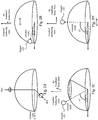
- Fig. 2A which illustrates a spherical coordinate system overlaid upon Cartesian axes (x, y, z).
- the z-axis serves as the azimuth (Az) rotation axis of the two-axis gimbal and the y-axis serves at the elevation (El) rotation axis of the two-axis gimbal.
- the LOS is directed based upon motion of the Az and El gimbals about their respective axes.
- body pitch and roll accelerations are coupled to the LOS by the sine of the elevation.
- the LOS inertial sensor is aligned with the bearing and motor of the elevation axis (the elevation control authority axis), regardless of elevation, in order to allow freedom of movement in the El.
- the LOS inertial sensor is only aligned with the azimuth axis (the control authority axis) at 0° deflection.
- the azimuth control authority axis and the azimuth inertial feedback axis become out of alignment ( Fig. 2C ).
- 71% of the aircraft body roll motion is coupled onto the LOS when looking towards the front or rear of the aircraft.
- 71% of the aircraft body pitch motion is so coupled.
- the SNR degrades to a point where a coordinate frame switch is needed to maintain azimuth gimbal axis control.
- the feedback sense axis for azimuth control may switch from the LOS inertial sensor to a sensor in the aircraft body reference frame, resulting in a loss of inertial reference frame line of sight control.
- the azimuth inertial feedback axis and bearing/motor pair are orthogonal ( Fig. 2D ). At this position, azimuth pointing control is completely lost, as rotation about the azimuth axis does not change the LOS pointing direction ("gimbal lock").
- two-axis gimbal systems which further include a two-axis beam steering mirror, inserted into the optical path of the imaging sensor or beam director.
- This mirror may be referred to as a fast steering mirror (FSM) as its responsivity is several times faster than the classical mass stabilized gimbal axis.
- FSM fast steering mirror
- the FSM is coupled to the two-axis gimbal so that it moves with the LOS, as directed by the gimbal set ("gimbal LOS").
- gimbal LOS gimbal LOS
- the FSM is aligned on both the elevation and azimuth gimbal axes and is further capable of deflection in two directions, independent of the gimbal set ("FSM deflection").
- the LOS inertial sensor may be mounted to the FSM.
- the FSM moves with respect to the gimbal LOS to achieve the net LOS.
- the FSM provides all LOS pointing control, with no help from the gimbal set.
- the FSM possesses a finite deflection range and may encounter mechanical stops when attempting to stabilize the LOS due to base motion of the vehicle.
- certain base motions e.g., relatively large base motions
- the FSM may be unable to completely execute desired pointing commands due to these mechanical limits, resulting in degraded LOS stabilization.
- Embodiments of the present disclosure relate to control systems and methodologies for improved azimuthal pointing control in two-axis gimbal systems.
- the disclosed embodiments may restore azimuth inertial pointing at near-nadir elevations. Under certain conditions, inertial pointing may be recovered at about nadir.
- the improved pointing system may include a two-axis elevation-azimuth gimbal mounted to a moveable platform (e.g., a vehicle such as an aircraft, land-based vehicle, water-based vehicle, or the like).
- a two-axis pointing device such as a fast steering mirror (FSM)
- FSM fast steering mirror
- the system may further include sensors adapted to measure motion of the two-axis gimbal and the two-axis pointing device.
- the sensors may include inertial sensors for measuring motion of the line of sight with respect to the moveable platform.
- the sensors may also include rate and angle sensors for measuring motion of the azimuth gimbal with respect to the moveable platform.
- the pointing system may further include a plurality of processors in communication with the respective sensors and motors of the two-axis gimbal and two-axis pointing device, the plurality of processors capable of generating commands for motion of the two-axis gimbal and the two-axis pointing device.
- the improved pointing system may implement a control process that employs feedback from the two-axis pointing device in order to restore inertial pointing control to the azimuth gimbal.
- Figures 4A-4B illustrate the deflection of the FSM with respect to its neutral position (the gimbal LOS position) and mechanical range.
- the deflection of the two-axis pointing device may be used as a command for motion of the gimbal set. That is to say, the gimbal set may "follow" the deflection of the FSM so to move the gimbal LOS as close as possible to the net LOS achieved by the FSM.
- This coordinated motion of the two-axis pointing device with the gimbal set also has the advantage of inhibiting the two-axis pointing device from encountering mechanical limits that would inhibit its range of motion.
- the FSM moves closer to its center or neutral position, from which the FSM is capable of moving its maximum travel distance.
- the FSM is capable of counteracting greater base-motion disturbances than would otherwise be possible if the FSM were positioned closer to its mechanical limits, improving the stabilizing ability of the FSM.
- embodiments of the present disclosure may provide inertial pointing exactly at nadir in the case of limited vehicle base motion dynamics. For example, as long as the LOS inertial deflections remain within the field of regard of the FSM, inertial pointing is retained without the need for gimbal set following motion.
- FIG. 1 schematically illustrates an embodiment of a pointing system 100 of the present disclosure.
- the system 100 includes a two-axis gimbal 104, a two-axis pointing device 112, and a control system 116.
- motion of two-axis gimbal 104 and the two-axis pointing device 112 may be controlled by commands, issued from the control system 116, that direct the LOS of an imaging device 114 in desired directions (e.g., towards a target location 122).
- the imaging device 114 is an optical imaging device, such as a still or video camera.
- the imaging device 114 is an electro-optical transmitter (e.g., a laser).
- electro-optical transmitter e.g., a laser
- embodiments of the disclosure may be adapted for use with any electro optic transmitter or receiver, alone or in combination, as necessary.
- the platform 102 may be any structure upon which the two-axis gimbal 104 may be mounted.
- the platform 102 is a moveable platform, such as a vehicle (e.g., a land-based vehicle, water-based vehicle, aircraft, etc.).
- the platform 102 may be a stationary platform.
- the two-axis gimbal 104 may include two gimbals, one mounted upon the other, with orthogonal pivot axes. Assuming the horizon as a reference plane, the first gimbal may be oriented with its axis of rotation perpendicular to the reference plane, designated azimuth gimbal 106. The second gimbal may be oriented perpendicular to the azimuth gimbal 106, designated elevation gimbal 110. For example, as illustrated in Figure 1 , the elevation gimbal 110 may be mounted to the azimuth gimbal 106. However, in alternative embodiments, any two-axis gimbal may be employed.
- the two-axis gimbal 104 may be directly coupled (e.g., kinematically coupled) to the platform 102 via the azimuth gimbal 106.
- the imaging device 114 may also be coupled to the two-axis gimbal 104 to direct the LOS axis of the imaging device.
- the two-axis pointing device 112 is a device which allows further steering of the LOS of the imaging device 114 by motion along two axes, independently of the two-axis gimbal 104.
- a plurality of mirrors, lenses, or other beam steering devices may be employed to direct the LOS from the imaging device 114 to the two-axis pointing device 112.
- the two-axis pointing device is a beam steering device capable of relatively faster movement than the two-axis gimbal 104.
- the two-axis pointing device 112 is a fast-steering mirror (FSM).
- FSM fast-steering mirror
- the two-axis pointing device 112 may include a first mirror, nominally mounted parallel to a flat base, allowing the first mirror to pivot about a central point near its surface.
- Actuators may be mounted in perpendicular axis pairs between the edges of the mirror and the base. The actuator pairs may be driven in a push-pull motion to rotate the mirror about two orthogonal axes, allowing two-axis angular scanning.
- the two-axis pointing device may be any type of optical beam steering device, such as refractive or reflective beam steering devices.
- the control system 116 may include a plurality of processors in electrical communication with a plurality of sensors.
- the sensors may include, but are not limited to, a rate and angle sensor 102A that is referenced to the platform and an LOS inertial sensor 104A.
- the rate and angle sensor 102A may provide measurements of the rate and angle of the azimuth gimbal 106 with respect to the platform 102.
- the rate and angle sensor 102A may be a tachometer for rate sensing and a resolver or encoder for angle sensing.
- the LOS inertial sensor 104A may be a two-axis gyroscope or two single axis gyroscopes mounted to a lens within the optical path of the LOS.
- the sensors 102A, 104A may be further adapted to output signals representative of the detected motions to the control system 116.
- the control system 116 may also be in communication with the two-axis gimbal 104, the two-axis pointing device 112, and a command computing device 124.
- the pointing system 100 when the pointing system 100 is mounted to a platform 102 in motion, in order to maintain the LOS 120 pointed at the target 122, the pointing system 100 must move so as to counteract the underlying motion of the platform 102, as well as any relative motion of the target 122 with respect to the two-axis gimbal 104 and the platform 102.
- the control system 116 may receive commands from the command computing device 124 for commanding motion of the two-axis gimbal 104 to follow the relative motion of the target 122 with respect to the two-axis gimbal. However, the commands from the command computing device 124 do not account for the base motion of the moving platform 102. Accordingly, the control system 116 may further receive feedback from the sensors 102A, 104A reflecting the underlying motion of the platform 102. The control system 116 may employ both the commands received from the command computing device 124 and the feedback from sensors 102A, 104A to generate new commands for movement of the two-axis gimbal 104 and the two-axis pointing device 112.
- Fig. 5 presents a schematic illustration of a control process 500 implemented by the control system 116 for azimuthal pointing of the system 100 when the deflection of the elevation gimbal 110 is outside the nadir/near-nadir region.
- the control process 500 may be employed at elevation deflections less than about 60°, preferably less than about 80°.
- the exact range of elevation gimbal deflections over which the control process 500 is performed depends upon the servo tuning of a particular installation of the pointing system 100, as reflected in the signal to noise ratio (SNR) of the azimuth inertial rate feedback. Accordingly, one of ordinary skill in the art may determine acceptable ranges of SNR for azimuthal pointing control employing the process 500 on a deployment-by-deployment basis.
- SNR signal to noise ratio
- the control process 500 may employ the LOS inertial sensor 104A to measure the base motion of the platform 102 with respect to the gimbal LOS 120.
- the control process 500 also receives, as input, commands representative of relative target motion from the command computing device 124. Movement of the azimuth gimbal 106 provides relatively coarse stabilization of the LOS 120, while movement of the two-axis pointing device 112 provides relatively fine stabilization of the LOS 120.
- control process 500 has been labeled with operations 501-507. However, it may be understood that the control process 500 is a continuous process performed by the control system 116 and is not limited to particular starting or ending point.
- base motion accelerations of the platform 102 occur.
- the base motion accelerations of the platform 102 are coupled to the LOS inertial sensor 104A through the two-axis gimbal 104 kinematically mounted to the platform 102. These base motions torque the LOS inertial sensor 104A in the inertial reference frame of the LOS 120 and introduce image instability.
- the LOS inertial sensor 104A observes the coupled base motion accelerations on the azimuth feedback sense axis with respect to the gimbal LOS 120 and outputs the sensed inertial rate to a first control processor 116A.
- the control processor 116A further receives signals from the command computing system 124 commanding motion of the azimuth gimbal 104 to follow the motion of the target 122 with respect to the two-axis gimbal 104 and platform 102.
- the signals from the command computing system 124 may include an angular rate command for a desired sensor line of sight pan rate. Based upon the sensed inertial rate and the angular rate command, the control processor 116A may generate separate commands for motion of the azimuth gimbal 106 and the two-axis pointing device 112.
- the first control processor 116A In order to generate motion commands for each of the azimuth gimbal 106 and the two-axis pointing device 112, the first control processor 116A generates an inertial error signal differencing the angular rate command and the observed inertial rate measured along the feedback sense axis of the LOS inertial sensor 104A in operation 504.
- the inertial error signal is representative of the difference between the currently measured angular rate of the gimbal LOS 120 and a desired angular rate of the gimbal LOS 120.
- Separate commands may be provided to both the azimuth gimbal 106 and the two-axis pointing device 112 in order to minimize the inertial error signal as much as possible. By minimizing the inertial error signal, the difference between a desired LOS and the actual LOS is reduced to greatest degree possible.
- commands for motion of the azimuth gimbal 106 are generated by the control processor 116A and provided to an azimuth motor and amplifier in communication with the azimuth gimbal 106.
- the control processor 116A applies a pre-defined control law to minimize the inertial error signal.
- the control law may be proportional plus integral control.
- the azimuth motor and amplifier move the azimuth gimbal 106 along the control authority axis to minimize the inertial rate error.
- the remaining, residual rate error represents the coarse stabilization performance of the control system 116.
- commands for motion of the two-axis pointing system 112 are generated.
- the control processor 116A integrates the coarse inertial rate error signal and transmits this signal to a second control processor 116B.
- the integrated rate error signal is not suitable for use as an input command for motion of the two-axis pointing device.
- the control processor 116B operates on the received integrated rate error to generate commands suitable for the two-axis pointing system 112 and outputs commands for the two-axis pointing device 112.
- operations on the integrated rate error may include phase and amplitude corrections as well as rotation into the frame of reference of the two-axis pointing device 112.
- the commands output by the control processor 116B are received by the two-axis pointing device 112.
- the two-axis pointing device 112 may be a two-axis fast steering mirror inserted into the optical path of the imaging device 114.
- the two-axis pointing device 112 may dynamically steer the optical axis of the imaging device 114 by an amount approximately equal in magnitude, and opposite in direction, to the integrated inertial rate error, further reducing the LOS inertial error (operation 507).
- the remaining residual rate error represents the fine stabilization performance of the pointing system 100.
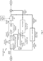
- FIG. 6 presents a schematic illustration of a control process 600 implemented by the control system 116 for azimuthal pointing of the system 100 when the deflection of the elevation gimbal 110 is within the nadir/near-nadir region.
- the control process 600 is operative to control the azimuth gimbal 106 and two-axis pointing device 112 for LOS pointing.
- the control process 600 employs the LOS inertial sensor 104A for pointing control of the two-axis pointing device 112, allowing LOS inertial pointing control to be maintained.
- controlling LOS pointing only by the two-axis pointing device 112 may cause the two-axis pointing device 112 to reach its mechanical limits and be unable to fully move in a desired direction.
- the process 600 may also employ the output deflection of the two-axis pointing device 112 to further steer the azimuth gimbal 106 in a manner which follows the two-axis pointing device 112. As the range of motion of the azimuth gimbal 106 is much larger than the two-axis pointing device 112, this motion of the azimuth gimbal 106 may inhibit the two-axis pointing device 112 from reaching its mechanical limits.
- control process 600 may be employed at elevation deflections greater than or equal to 60°, greater than or equal to 70°, greater than or equal to 80°, etc.
- the exact range of elevation gimbal deflections over which the control process 600 is performed may depend upon the servo tuning of a particular installation of the pointing system 100, as reflected in the SNR of the azimuth inertial rate feedback. Accordingly, one of ordinary skill in the art may determine unacceptable ranges of SNR for azimuthal pointing control employing the process 500 on a deployment-by-deployment basis and instead employ the control process 600 within this regime.
- control process 600 has been labeled with operations 601-607. However, it may be understood that the control process 600 is a continuous process performed by the control system 116 and is not limited to particular starting or ending point.
- base motion accelerations of the platform 102 occur during motion of the platform 102.
- the base motion accelerations of the platform 102 are coupled to the LOS inertial sensor 104A through the two-axis gimbal 104 kinematically mounted to the platform 102.
- These base motions torque the LOS inertial sensor 104A in the inertial reference frame of the LOS 120 and introduce image instability.
- the LOS inertial sensor 104A measures the coupled base motion accelerations on the azimuth feedback sense axis, representative of the acceleration of the moving platform 102, in the LOS inertial frame, due to the motion of the moveable platform 102.
- the LOS inertial sensor 104A further outputs a signal representative of the measured acceleration.
- the inertial rate measured by the LOS inertial sensor 104A is received by a third control processor 116C, in communication with the two-axis pointing device 112, rather than control processor 116A in communication with the azimuth gimbal.
- the control processor 116C also receives signals (e.g., angular rate commands) from the command computing system 124 commanding motion of the pointing system 100 to follow the motion of the target 122 with respect to the two-axis gimbal 104.
- the signals from the command computing system 124 may include an angular rate command for a desired sensor line of sight pan rate.
- the control processor 116C In operation 606, the control processor 116C generates a command signal commanding deflection of the two-axis pointing device 112 and outputs commands for the two-axis pointing device 112.
- the command signal is based upon the measured acceleration of the moveable platform 102 received from the LOS inertial sensor 104A and the relative target motion with respect to the two-axis gimbal 104.
- the control processor 116C generates an inertial error signal by differencing the angular rate command and the observed inertial rate measured along the feedback sense axis of the LOS inertial sensor 104A.
- the inertial error signal is representative of the difference between the currently measured angular rate of the two-axis pointing device 112 and a desired angular rate of the two-axis pointing device 112.
- control processor 116C may also integrate the inertial error and operate on the integrated inertial error in order to generate commands suitable for the two-axis pointing system 112.
- operations may include phase and amplitude corrections as well as rotation into the frame of reference of the two-axis pointing device 112.
- the commands output by the control processor 116C are received by the two-axis pointing device 112.
- the two-axis pointing device 112 may be a two-axis fast steering mirror inserted into the optical path of the imaging device 114.
- the two-axis pointing device 112 may dynamically steer the optical axis of the imaging device 114 by an amount approximately equal in magnitude, and opposite in direction, to the integrated inertial rate error, reducing the LOS inertial error (operation 607).
- the remaining, residual rate error represents the stabilization performance of the two-axis pointing device 112.
- control of the motion of the azimuth gimbal 106 will now be discussed with reference to operations 601-605.
- base motion accelerations of the platform 102 occur during motion of the platform 102.
- the base motion accelerations of the platform 102 are coupled to the rate and angle sensor 102A.
- the rate and angle sensor 102A measures the acceleration of the azimuth gimbal relative to the platform 102, due to the motion of the moveable platform.
- the sensor 102A may further output the sensed gimbal rate and a gimbal position calculated from the measured motion of the azimuth gimbal 106 relative to the platform 102.
- the gimbal position may be provided to the control processor 116D, while the gimbal rate may be provided to a control processor 116E.
- control processor 116D may generate an azimuth rate command and output this azimuth rate command to the control processor 116E.
- the azimuth rate command may be based upon the deflection of the two-axis pointing device and the gimbal angle feedback.
- the rate command may command movement of the azimuth gimbal 106 so as to counteract the deflection of the two-axis pointing device 112.
- the process 600 may inhibit the two-axis pointing device from reaching its mechanical limits.
- the rate command output by the control processor 116D may be further modified by the angular rate command output by the command computing system 124 (operation 604B), prior to receipt by the control processor 116E. That is to say, the command input to the azimuth gimbal 106 may be based upon the relative motion of the target 122 with respect to the azimuth gimbal 106 as well as the deflection of the two-axis pointing device 112. This composite command is input to the control processor 116E and has the benefit of moving the azimuth gimbal 106 to account for both movement of the two-axis pointing device 112 as well as the target movement.
- commands for motion of the azimuth gimbal 106 are generated by the control processor 116E and provided to an azimuth motor and amplifier in communication with the azimuth gimbal 106.
- the control processor 116E receives both the composite command signal as well as the gimbal rate feedback.
- the control processor 116E differences the composite rate command with the gimbal rate feedback to determine an error signal and further applies a pre-defined control law to minimize the error signal.
- the control law may be proportional plus integral control.
- the azimuth motor and amplifier move the azimuth gimbal 106 along the control authority axis to minimize the inertial rate error and maximize mechanical travel of the two-axis pointing device 112 (operation 605).
- the remaining, residual rate error represents the stabilization performance of the azimuth gimbal 106.
- the combination of LOS stabilization provided by the azimuth gimbal 106 and the two-axis pointing device 112 are symbolically represented in Figure 6 as ⁇ , the final LOS position after one control loop. While the control process 600 has been discussed in terms of sequential operations, it may be understood that control of the azimuth gimbal 106 and the two-axis pointing device 112 may be performed continuously and concurrently for LOS positioning control.
- the above-described systems and methods can be implemented in digital electronic circuitry, in computer hardware, firmware, and/or software.
- the implementation can be as a computer program product.
- the implementation can, for example, be in a machine-readable storage device, for execution by, or to control the operation of, data processing apparatus.
- the implementation can, for example, be a programmable processor, a computer, and/or multiple computers.
- a computer program can be written in any form of programming language, including compiled and/or interpreted languages, and the computer program can be deployed in any form, including as a stand-alone program or as a subroutine, element, and/or other unit suitable for use in a computing environment.
- a computer program can be deployed to be executed on one computer or on multiple computers at one site.
- Method steps can be performed by one or more programmable processors executing a computer program to perform functions of the invention by operating on input data and generating output. Method steps can also be performed by and an apparatus can be implemented as special purpose logic circuitry.
- the circuitry can, for example, be a FPGA (field programmable gate array) and/or an ASIC (application specific integrated circuit).
- Subroutines and software agents can refer to portions of the computer program, the processor, the special circuitry, software, and/or hardware that implement that functionality.
- processors suitable for the execution of a computer program include, by way of example, both general and special purpose microprocessors, and any one or more processors of any kind of digital computer.
- a processor receives instructions and data from a read-only memory or a random access memory or both.
- the essential elements of a computer are a processor for executing instructions and one or more memory devices for storing instructions and data.
- a computer can include, can be operatively coupled to receive data from and/or transfer data to one or more mass storage devices for storing data (e.g., magnetic, magneto-optical disks, or optical disks).
- Data transmission and instructions can also occur over a communications network.
- Information carriers suitable for embodying computer program instructions and data include all forms of non-volatile memory, including by way of example semiconductor memory devices.
- the information carriers can, for example, be EPROM, EEPROM, flash memory devices, magnetic disks, internal hard disks, removable disks, magneto-optical disks, CD-ROM, and/or DVD-ROM disks.
- the processor and the memory can be supplemented by, and/or incorporated in special purpose logic circuitry.
- the above described techniques can be implemented on a computer having a display device.
- the display device can, for example, be a cathode ray tube (CRT) and/or a liquid crystal display (LCD) monitor.
- CTR cathode ray tube
- LCD liquid crystal display
- the interaction with a user can, for example, be a display of information to the user and a keyboard and a pointing device (e.g., a mouse or a trackball) by which the user can provide input to the computer (e.g., interact with a user interface element).
- Other kinds of devices can be used to provide for interaction with a user.
- Other devices can, for example, be feedback provided to the user in any form of sensory feedback (e.g., visual feedback, auditory feedback, or tactile feedback).
- Input from the user can, for example, be received in any form, including acoustic, speech, and/or tactile input.
- the above described techniques can be implemented in a distributed computing system that includes a back-end component.
- the back-end component can, for example, be a data server, a middleware component, and/or an application server.
- the above described techniques can be implemented in a distributing computing system that includes a front-end component.
- the front-end component can, for example, be a client computer having a graphical user interface, a Web browser through which a user can interact with an example implementation, and/or other graphical user interfaces for a transmitting device.
- the components of the system can be interconnected by any form or medium of digital data communication (e.g., a communication network). Examples of communication networks include a local area network (LAN), a wide area network (WAN), the Internet, wired networks, and/or wireless networks.
- LAN local area network
- WAN wide area network
- the Internet wired networks, and/or wireless networks.
- the system can include clients and servers.
- a client and a server are generally remote from each other and typically interact through a communication network.
- the relationship of client and server arises by virtue of computer programs running on the respective computers and having a client-server relationship to each other.
- Packet-based networks can include, for example, the Internet, a carrier internet protocol (IP) network (e.g., local area network (LAN), wide area network (WAN), campus area network (CAN), metropolitan area network (MAN), home area network (HAN)), a private IP network, an IP private branch exchange (IPBX), a wireless network (e.g., radio access network (RAN), 802.11 network, 802.16 network, general packet radio service (GPRS) network, HiperLAN), and/or other packet-based networks.
- IP carrier internet protocol
- RAN radio access network
- 802.11 802.11 network
- 802.16 general packet radio service
- GPRS general packet radio service
- HiperLAN HiperLAN
- Circuit-based networks can include, for example, the public switched telephone network (PSTN), a private branch exchange (PBX), a wireless network (e.g., RAN, bluetooth, code-division multiple access (CDMA) network, time division multiple access (TDMA) network, global system for mobile communications (GSM) network), and/or other circuit-based networks.
- PSTN public switched telephone network
- PBX private branch exchange
- CDMA code-division multiple access
- TDMA time division multiple access
- GSM global system for mobile communications
- the transmitting device can include, for example, a computer, a computer with a browser device, a telephone, an IP phone, a mobile device (e.g., cellular phone, personal digital assistant (PDA) device, laptop computer, electronic mail device), and/or other communication devices.
- the browser device includes, for example, a computer (e.g., desktop computer, laptop computer) with a World Wide Web browser (e.g., Microsoft® Internet Explorer® available from Microsoft Corporation, Mozilla® Firefox available from Mozilla Corporation).
- the mobile computing device includes, for example, a Blackberry®.
- Comprise, include, and/or plural forms of each are open ended and include the listed parts and can include additional parts that are not listed. And/or is open ended and includes one or more of the listed parts and combinations of the listed parts.
Landscapes
- Engineering & Computer Science (AREA)
- General Engineering & Computer Science (AREA)
- Physics & Mathematics (AREA)
- General Physics & Mathematics (AREA)
- Multimedia (AREA)
- Signal Processing (AREA)
- Mechanical Engineering (AREA)
- Remote Sensing (AREA)
- Radar, Positioning & Navigation (AREA)
- Optics & Photonics (AREA)
- Aviation & Aerospace Engineering (AREA)
- Position Input By Displaying (AREA)
- Studio Devices (AREA)
Claims (15)
- Verfahren (600) zum azimutalen Zeigen einer Sichtlinie (line of sight, LOS) (120), umfassend die folgenden Schritte:Messen, an einem zweiachsigen Kardanrahmen (104), der über einen Azimutkardanrahmen (106), einen Erhebungskardanrahmen (110) und eine Sichtlinie (120) verfügt und kinematisch mit einer beweglichen Plattform (102) gekoppelt ist:einer Beschleunigung der beweglichen Plattform (102) in einem Inertialsystem der Sichtlinie (120), in Folge einer Bewegung der beweglichen Plattform (102); undeiner Beschleunigung des Azimutkardanrahmens (106) im Verhältnis zu der Plattform (102), in Folge der Bewegung der beweglichen Plattform (102);Erzeugen, durch einen oder mehrere Prozessoren (116C-E), eines ersten Befehlssignals zum Befehlen der Ablenkung einer zweiachsigen Zeigevorrichtung (112), die kinematisch mit dem zweiachsigen Kardanrahmen (104) gekoppelt und in dem optischen Pfad der Sichtlinie (120) positioniert ist, das erste Befehlssignal basierend auf der gemessenen Beschleunigung der beweglichen Plattform (102) und einer relativen Zielbewegung im Hinblick auf den Azimutkardanrahmen (106);Messen, im Sichtlinien-Inertialsystem, der Ablenkung der zweiachsigen Zeigevorrichtung (112) als Reaktion auf das erste Befehlssignal; undErzeugen, durch den einen oder die mehreren Prozessoren (116C-E), eines zweiten Befehlssignals zum Befehlen der Ablenkung des Azimutkardanrahmens (106) basierend auf der Ablenkung der zweiachsigen Zeigevorrichtung (112) und der gemessenen Beschleunigung des Azimutkardanrahmens (106).
- Verfahren (600) nach Anspruch 1, wobei die ersten und zweiten Befehlssignale erzeugt werden, wenn der Erhebungskardanrahmen (110) in einem ausgewählten Winkel orientiert ist.
- Verfahren (600) nach Anspruch 1, wobei das Erzeugen des zweiten Befehlssignals ferner das Erzeugen des zweiten Befehlssignals basierend auf der relativen Zielbewegung umfasst.
- Verfahren (600) nach Anspruch 1, ferner umfassend das Erzeugen, durch den einen oder die mehreren Prozessoren (116C-E), eines dritten Befehlssignals zum Befehlen der Ablenkung des Azimutkardanrahmens (106), das dritte Befehlssignal basierend auf der gemessenen Beschleunigung des Azimutkardanrahmens (106) und dem zweiten Befehlssignal, wobei sich bei Empfang des dritten Befehlssignals durch den Azimutkardanrahmen (106) der Azimutkardanrahmen (106) bewegt, um mindestens einem Abschnitt der Ablenkung der zweiachsigen Zeigevorrichtung (112) entgegenzuwirken.
- Verfahren (600) nach Anspruch 4, ferner umfassend das Erzeugen, durch den einen oder die mehreren Prozessoren (116C-E), einer aktualisierten relativen Zielbewegung basierend auf der Ablenkung der zweiachsigen Zeigevorrichtung (112) und der Ablenkung des Azimutkardanrahmens (106) als Reaktion auf das dritte Befehlssignal.
- Verfahren (600) nach Anspruch 1, wobei das Erzeugen des ersten Befehlssignals ferner das Konvertieren der Beschleunigung der beweglichen Plattform (102) und der Zielbeschleunigung in ein Referenzsystem der zweiachsigen Zeigevorrichtung (112) umfasst.
- Verfahren (600) nach Anspruch 1, wobei das Erzeugen des zweiten Befehlssignals ferner das Konvertieren der Beschleunigung des Azimutkardanrahmens (106) in einen Azimutkardanrahmenwinkel in dem Referenzsystem der beweglichen Plattform (102) und das Konvertieren der Ablenkung der zweiachsigen Zeigevorrichtung (112) aus einem Referenzsystem der zweiachsigen Zeigevorrichtung (112) in eine Ablenkung der zweiachsigen Zeigevorrichtung (112) in dem Referenzsystem der beweglichen Plattform (102) umfasst.
- Azimutales Zeigesystem (100), umfassend:einen zweiachsigen Kardanrahmen (104), der kinematisch mit einer beweglichen Plattform (102) gekoppelt ist, wobei der zweiachsige Kardanrahmen (104) ferner einen Erhebungskardanrahmen (110), einen Azimutkardanrahmen (106) und eine Sichtlinie (120) einschließt;eine zweiachsige Zeigeeinrichtung (112), die kinematisch mit dem zweiachsigen Kardanrahmen (104) gekoppelt und in den optischen Pfad der Sichtlinie (120) eingeführt ist;einen ersten Sensor (102A), der geeignet ist zum Messen des Winkels und der Rate des Azimutkardanrahmens (106) im Verhältnis zu der beweglichen Plattform (102);einen zweiten Sensor (104A), der geeignet ist zum Messen der Inertialbewegung der Sichtlinie;einen oder mehrere Prozessoren (116C-E), geeignet zum Erzeugen:eines ersten Befehlssignals zum Befehlen der Ablenkung der zweiachsigen Zeigevorrichtung (112), wobei das erste Befehlssignal basiert auf:einer Messung durch den zweiten Sensor (104A) einer Beschleunigung der beweglichen Plattform (102) in einem Inertialsystem der Sichtlinie (120) aufgrund einer Bewegung der beweglichen Plattform (102); und einer relativen Zielbewegung im Hinblick auf den Azimutkardanrahmen (106); undeinem zweiten Befehlssignal zum Befehlen der Ablenkung des Azimutkardanrahmens (106), wobei das zweite Befehlssignal basiert auf:der Ablenkung der zweiachsigen Zeigevorrichtung (112) als Reaktion auf das erste Befehlssignal; undeiner Messung durch den ersten Sensor (102A) einer Beschleunigung des Azimutkardanrahmens (106) im Hinblick auf die bewegliche Plattform (102), in Folge der Bewegung der beweglichen Plattform (102).
- System (100) nach Anspruch 8, wobei der eine oder die mehreren Prozessoren (116C-E) ferner geeignet ist bzw. sind, das zweite Befehlssignal basierend auf dem Ratenbefehl zu erzeugen.
- System (100) nach Anspruch 9, wobei der eine oder die mehreren Prozessoren (116C-E) ferner geeignet ist bzw. sind, ein drittes Befehlssignal zum Befehlen der Ablenkung des Azimutkardanrahmens zu erzeugen, wobei das dritte Befehlssignal auf der Beschleunigung des Azimutkardanrahmens und dem zweiten Befehlssignal basiert.
- System (100) nach Anspruch 8, wobei die zweiachsige Zeigevorrichtung (112) eine Optikstrahl-Lenkvorrichtung umfasst, die angepasst ist, die Sichtlinie (120) im Hinblick auf zwei Rotationsachsen zu lenken.
- Nicht-flüchtiges computerlesbares Medium, in das computerlesbare Programmcodes zum Vergleichen von Entscheidungsoptionen eingebettet sind, wobei die computerlesbaren Programmcodes Anweisungen enthalten, die bei ihrer Ausführung durch den einen oder die mehreren Prozessoren gemäß Anspruch 8 bewirken, dass das System gemäß Anspruch 8 das Verfahren gemäß Anspruch 1 durchführt.
- Computerlesbares Medium nach Anspruch 12, das ferner Anweisungen einschließt, die bei ihrer Ausführung bewirken, dass der Prozessor (116C-E) das zweite Befehlssignal basierend auf der relativen Zielbewegung erzeugt.
- Computerlesbares Medium nach Anspruch 12, das ferner Anweisungen einschließt, die bei ihrer Ausführung bewirken, dass der Prozessor (116C-E) ein drittes Befehlssignal zum Befehlen der Ablenkung des Azimutkardanrahmens (106) basierend auf der gemessenen Beschleunigung des Azimutkardanrahmens (106) und dem zweiten Befehlssignal erzeugt; und
das vorzugsweise ferner Anweisungen einschließt, die bei ihrer Ausführung bewirken, dass der Prozessor (116C-E) ein aktualisiertes Befehlssignal zum Befehlen der Ablenkung des Azimutkardanrahmens (106) basierend auf der Ablenkung der zweiachsigen Zeigevorrichtung (112) und der Ablenkung des Azimutkardanrahmens (106) als Reaktion auf das dritte Befehlssignal erzeugt. - Computerlesbares Medium nach Anspruch 12, das ferner Anweisungen einschließt, die bei ihrer Ausführung bewirken, dass der Prozessor (116C-E) die Beschleunigung des Azimutkardanrahmen (106) in einen Azimutkardanrahmenwinkel in dem Referenzsystem der beweglichen Plattform (102) konvertiert und die Ablenkung der zweiachsigen Zeigevorrichtung (112) aus einem Referenzsystem der zweiachsigen Zeigevorrichtung (112) in eine Ablenkung der zweiachsigen Zeigevorrichtung (112) in dem Referenzsystem der beweglichen Plattform (102) konvertiert.
Applications Claiming Priority (2)
| Application Number | Priority Date | Filing Date | Title |
|---|---|---|---|
| US14/072,559 US9482530B2 (en) | 2013-11-05 | 2013-11-05 | Nadir/zenith inertial pointing assistance for two-axis gimbals |
| PCT/US2014/052498 WO2015069366A1 (en) | 2013-11-05 | 2014-08-25 | Nadir/zenith inertial pointing assistance for two-axis gimbals |
Publications (2)
| Publication Number | Publication Date |
|---|---|
| EP3066824A1 EP3066824A1 (de) | 2016-09-14 |
| EP3066824B1 true EP3066824B1 (de) | 2019-03-06 |
Family
ID=51519177
Family Applications (1)
| Application Number | Title | Priority Date | Filing Date |
|---|---|---|---|
| EP14761930.8A Active EP3066824B1 (de) | 2013-11-05 | 2014-08-25 | Nadir-/zenithbezogene trägheit-ausrichtungshilfe für zweiachsenkardane |
Country Status (6)
| Country | Link |
|---|---|
| US (1) | US9482530B2 (de) |
| EP (1) | EP3066824B1 (de) |
| JP (1) | JP6286537B2 (de) |
| CA (1) | CA2927193C (de) |
| IL (1) | IL245319B (de) |
| WO (1) | WO2015069366A1 (de) |
Families Citing this family (14)
| Publication number | Priority date | Publication date | Assignee | Title |
|---|---|---|---|---|
| KR102155895B1 (ko) * | 2015-11-26 | 2020-09-14 | 삼성전자주식회사 | 객체를 추적하여 영상을 수신하는 방법 및 장치 |
| US10502574B2 (en) * | 2016-09-20 | 2019-12-10 | Waymo Llc | Devices and methods for a sensor platform of a vehicle |
| US10277084B1 (en) | 2016-10-19 | 2019-04-30 | Waymo Llc | Planar rotary transformer |
| CN110291013B (zh) * | 2018-11-30 | 2021-12-17 | 深圳市大疆创新科技有限公司 | 云台的控制方法、云台及无人飞行器 |
| JP6960238B2 (ja) * | 2017-04-28 | 2021-11-05 | キヤノン株式会社 | 像ブレ補正装置及びその制御方法、プログラム、記憶媒体 |
| CN108919841B (zh) * | 2018-08-24 | 2022-03-08 | 湖北三江航天红峰控制有限公司 | 一种光电跟踪系统的复合轴控制方法及系统 |
| CN109631879B (zh) * | 2018-11-15 | 2022-05-13 | 湖北三江航天红峰控制有限公司 | 一种正交锁紧的双轴转位机构 |
| CN110832423B (zh) * | 2018-11-28 | 2024-06-14 | 深圳市大疆创新科技有限公司 | 云台的控制方法、云台、移动平台和计算机可读存储介质 |
| FR3096771B1 (fr) * | 2019-06-03 | 2021-07-02 | Ixblue | Systme de visée comprenant un dispositif de visée orientable par rapport á une embase, apte á mettre en oeuvre un procedé de calibrage sur site simple et rapide |
| WO2021044422A1 (en) * | 2019-09-04 | 2021-03-11 | Lightyx Systems Ltd. | System and method for controlling a light projector in a construction site |
| CN111207746B (zh) * | 2020-03-03 | 2021-08-24 | 北京航空航天大学 | 一种惯性定位定向设备方位引出装置及其标校方法 |
| US11835705B2 (en) * | 2020-10-07 | 2023-12-05 | Raytheon Company | Optical sensor with Tx/Rx aperture sharing element (ASE) to block detection of the received active signal |
| US12000676B2 (en) | 2020-10-15 | 2024-06-04 | Raytheon Company | Optical sensor with Tx/Rx aperture sharing element (ASE) for processing passive and active signals |
| US11835709B2 (en) | 2021-02-09 | 2023-12-05 | Raytheon Company | Optical sensor with micro-electro-mechanical system (MEMS) micro-mirror array (MMA) steering of the optical transmit beam |
Family Cites Families (35)
| Publication number | Priority date | Publication date | Assignee | Title |
|---|---|---|---|---|
| US2077398A (en) * | 1934-10-03 | 1937-04-20 | Ludington Corp | Navigating instrument |
| US2740962A (en) * | 1950-01-05 | 1956-04-03 | Sperry Rand Corp | Three axis tracking system |
| US3230348A (en) * | 1951-09-01 | 1966-01-18 | Sperry Rand Corp | Missile guidance system |
| US3015457A (en) * | 1952-10-13 | 1962-01-02 | Northrop Corp | Azimuth control in a guidance system |
| US3027841A (en) * | 1952-10-13 | 1962-04-03 | Northrop Corp | Guidance system |
| US3181812A (en) * | 1952-12-08 | 1965-05-04 | Northrop Corp | Aircraft sextant mounting |
| US3312423A (en) * | 1962-09-10 | 1967-04-04 | Gen Motors Corp | Inertial guidance system with stellar correction |
| US3439427A (en) * | 1965-03-17 | 1969-04-22 | North American Rockwell | Method for navigating a space vehicle |
| US4148029A (en) * | 1976-10-13 | 1979-04-03 | Westinghouse Electric Corp. | System for estimating acceleration of maneuvering targets |
| US4179696A (en) * | 1977-05-24 | 1979-12-18 | Westinghouse Electric Corp. | Kalman estimator tracking system |
| US5225838A (en) * | 1980-12-29 | 1993-07-06 | Raytheon Company | All weather tactical strike system (AWTSS) and method of operation |
| US5163176A (en) * | 1980-12-29 | 1992-11-10 | Raytheon Company | All weather tactical strike system (AWTSS) and method of operation |
| US5172122A (en) * | 1980-12-29 | 1992-12-15 | Raytheon Company | All weather tactical strike system (AWISS) and method of operation |
| US4798462A (en) | 1985-12-20 | 1989-01-17 | Hughes Aircraft Company | Auto-boresight technique for self-aligning phase conjugate laser |
| JP2803072B2 (ja) | 1990-10-18 | 1998-09-24 | 富士写真フイルム株式会社 | 手振れ補正装置 |
| JPH11308604A (ja) * | 1998-04-24 | 1999-11-05 | Mitsubishi Electric Corp | ジンバル制御装置 |
| US6396235B1 (en) * | 2001-01-05 | 2002-05-28 | Engineered Support Systems, Inc. | Stabilized common gimbal |
| US6789437B2 (en) * | 2001-07-31 | 2004-09-14 | Northrop Grumman Systems Corporation | Apparatus for precision slewing of flatform-mounted devices |
| US7000883B2 (en) * | 2003-01-17 | 2006-02-21 | The Insitu Group, Inc. | Method and apparatus for stabilizing payloads, including airborne cameras |
| US8798450B2 (en) * | 2004-10-01 | 2014-08-05 | Flir Systems, Inc. | Gimbal system |
| US7095376B1 (en) * | 2004-11-30 | 2006-08-22 | L3 Communications Corporation | System and method for pointing and control of an antenna |
| US8179078B2 (en) | 2005-04-27 | 2012-05-15 | Sidman Adam D | Handheld or vehicle-mounted platform stabilization system |
| US7894144B2 (en) | 2006-06-09 | 2011-02-22 | Bae Systems Information And Electronic Systems Integration Inc. | High accuracy optical pointing apparatus |
| JP4709101B2 (ja) | 2006-09-01 | 2011-06-22 | キヤノン株式会社 | 自動追尾カメラ装置 |
| JP4982407B2 (ja) * | 2008-02-22 | 2012-07-25 | 株式会社東芝 | 移動体画像追尾装置及び方法 |
| IL192601A (en) * | 2008-07-03 | 2014-07-31 | Elta Systems Ltd | Discovery / Transmission Device, System and Method |
| US8436283B1 (en) | 2008-07-11 | 2013-05-07 | Davidson Technologies Inc. | System and method for guiding and controlling a missile using high order sliding mode control |
| US9217643B1 (en) * | 2009-01-08 | 2015-12-22 | Trex Enterprises Corp. | Angles only navigation system |
| US9681065B2 (en) | 2010-06-15 | 2017-06-13 | Flir Systems, Inc. | Gimbal positioning with target velocity compensation |
| US9032859B2 (en) * | 2011-11-30 | 2015-05-19 | Drs Sustainment Systems, Inc. | Harmonized turret with multiple gimbaled sub-systems |
| US8994836B2 (en) | 2012-03-14 | 2015-03-31 | Raytheon Company | Beam steering element feed forward command aiding architecture |
| US9435520B2 (en) * | 2012-08-16 | 2016-09-06 | Ascendant Engineering Solutions | Gimbal systems providing high-precision imaging capabilities in a compact form-factor |
| US9243931B2 (en) * | 2012-11-28 | 2016-01-26 | Drs Sustainment Systems, Inc. | AZ/EL gimbal housing characterization |
| IL223899A (en) * | 2012-12-26 | 2017-06-29 | Israel Aerospace Ind Ltd | Device control system, method and method |
| US9074888B2 (en) * | 2013-01-28 | 2015-07-07 | Drs Sustainment Systems, Inc. | Gyro drift cancelation |
-
2013
- 2013-11-05 US US14/072,559 patent/US9482530B2/en active Active
-
2014
- 2014-08-25 EP EP14761930.8A patent/EP3066824B1/de active Active
- 2014-08-25 JP JP2016527258A patent/JP6286537B2/ja active Active
- 2014-08-25 WO PCT/US2014/052498 patent/WO2015069366A1/en not_active Ceased
- 2014-08-25 CA CA2927193A patent/CA2927193C/en active Active
-
2016
- 2016-04-27 IL IL245319A patent/IL245319B/en active IP Right Grant
Non-Patent Citations (2)
| Title |
|---|
| HILKERT J M: "Inertially stabilized platform technology Concepts and principles", IEEE CONTROL SYSTEMS MAGAZINE, IEEE SEWRVICE CENTER, PISCATAWAY, NJ, US, vol. 28, no. 1, 1 February 2008 (2008-02-01), pages 26 - 46, XP011200053, ISSN: 0272-1708, DOI: 10.1109/MCS.2007.910256 * |
| RICK MILLER ET AL: "Gimbal system configurations and line-of-sight control techniques for small UAV applications", PROCEEDINGS OPTICAL DIAGNOSTICS OF LIVING CELLS II, vol. 8713, 31 May 2013 (2013-05-31), US, pages 871308, XP055347865, ISSN: 0277-786X, ISBN: 978-1-5106-1324-9, DOI: 10.1117/12.2015777 * |
Also Published As
| Publication number | Publication date |
|---|---|
| WO2015069366A1 (en) | 2015-05-14 |
| JP6286537B2 (ja) | 2018-02-28 |
| JP2016536886A (ja) | 2016-11-24 |
| US9482530B2 (en) | 2016-11-01 |
| US20160223327A1 (en) | 2016-08-04 |
| CA2927193C (en) | 2020-12-15 |
| EP3066824A1 (de) | 2016-09-14 |
| CA2927193A1 (en) | 2015-05-14 |
| IL245319A0 (en) | 2016-06-30 |
| IL245319B (en) | 2019-06-30 |
Similar Documents
| Publication | Publication Date | Title |
|---|---|---|
| CA2927193C (en) | Nadir/zenith inertial pointing assistance for two-axis gimbals | |
| JP5955449B2 (ja) | ビーム・ステアリング素子のフィードフォアワード・コマンドを補助するアーキテクチャ | |
| US4621266A (en) | Device for stabilizing and aiming an antenna, more particularly on a ship | |
| JP3488301B2 (ja) | ジンバル制御システム | |
| US8213803B2 (en) | Method and system for laser based communication | |
| US20100220390A1 (en) | High accuracy optical pointing apparatus | |
| CA2732310A1 (en) | System and method for precise real-time measurement of a target position and orientation relative to a base position, and control thereof | |
| KR100241672B1 (ko) | 평형 관절식 거울을 갖는 투시 장치 | |
| WO2000007134A1 (en) | Method and apparatus for generating navigation data | |
| Borrello | A multi stage pointing acquisition and tracking (PAT) control system approach for air to air laser communications | |
| US11549785B2 (en) | Arrangement and method for autoalignment of a stabilized subsystem | |
| JP4423371B2 (ja) | 空間安定装置 | |
| JP3393025B2 (ja) | 指向性アンテナ用三軸制御装置 | |
| JPH058885B2 (de) | ||
| RU2012115323A (ru) | Способ формирования сигнала компенсации фазовых искажений принимаемых сигналов, отраженных от облучаемого объекта визирования, с одновременным его инерциальным пеленгованием и инерциальным автосопровождением и система для его осуществления | |
| Murakoshi | Antenna stabilizing control system using a strapdown 2-axis Azimuth/Elevation method | |
| Hamilton | Strapdown optical stabilization system for EO sensors on moving platforms | |
| JP3234546B2 (ja) | 指向性アンテナ用三軸制御装置 | |
| JP3146393B2 (ja) | アンテナ指向装置 | |
| JPH0620164B2 (ja) | アンテナ装置 |
Legal Events
| Date | Code | Title | Description |
|---|---|---|---|
| PUAI | Public reference made under article 153(3) epc to a published international application that has entered the european phase |
Free format text: ORIGINAL CODE: 0009012 |
|
| 17P | Request for examination filed |
Effective date: 20160527 |
|
| AK | Designated contracting states |
Kind code of ref document: A1 Designated state(s): AL AT BE BG CH CY CZ DE DK EE ES FI FR GB GR HR HU IE IS IT LI LT LU LV MC MK MT NL NO PL PT RO RS SE SI SK SM TR |
|
| AX | Request for extension of the european patent |
Extension state: BA ME |
|
| DAX | Request for extension of the european patent (deleted) | ||
| STAA | Information on the status of an ep patent application or granted ep patent |
Free format text: STATUS: EXAMINATION IS IN PROGRESS |
|
| 17Q | First examination report despatched |
Effective date: 20180327 |
|
| REG | Reference to a national code |
Ref country code: DE Ref legal event code: R079 Ref document number: 602014042373 Country of ref document: DE Free format text: PREVIOUS MAIN CLASS: H04N0005232000 Ipc: F16M0011120000 |
|
| RIC1 | Information provided on ipc code assigned before grant |
Ipc: F41G 3/22 20060101ALI20180809BHEP Ipc: F16M 11/12 20060101AFI20180809BHEP Ipc: F16M 11/18 20060101ALI20180809BHEP Ipc: H04N 5/232 20060101ALI20180809BHEP |
|
| GRAP | Despatch of communication of intention to grant a patent |
Free format text: ORIGINAL CODE: EPIDOSNIGR1 |
|
| STAA | Information on the status of an ep patent application or granted ep patent |
Free format text: STATUS: GRANT OF PATENT IS INTENDED |
|
| RIC1 | Information provided on ipc code assigned before grant |
Ipc: H04N 5/232 20060101ALI20180831BHEP Ipc: G01C 15/00 20060101ALI20180831BHEP Ipc: G02B 27/64 20060101ALI20180831BHEP Ipc: F16M 11/12 20060101AFI20180831BHEP Ipc: G01C 19/42 20060101ALI20180831BHEP Ipc: F16M 11/18 20060101ALI20180831BHEP Ipc: F41G 3/22 20060101ALI20180831BHEP Ipc: G01P 15/00 20060101ALI20180831BHEP |
|
| INTG | Intention to grant announced |
Effective date: 20180925 |
|
| GRAS | Grant fee paid |
Free format text: ORIGINAL CODE: EPIDOSNIGR3 |
|
| GRAA | (expected) grant |
Free format text: ORIGINAL CODE: 0009210 |
|
| STAA | Information on the status of an ep patent application or granted ep patent |
Free format text: STATUS: THE PATENT HAS BEEN GRANTED |
|
| AK | Designated contracting states |
Kind code of ref document: B1 Designated state(s): AL AT BE BG CH CY CZ DE DK EE ES FI FR GB GR HR HU IE IS IT LI LT LU LV MC MK MT NL NO PL PT RO RS SE SI SK SM TR |
|
| REG | Reference to a national code |
Ref country code: GB Ref legal event code: FG4D |
|
| REG | Reference to a national code |
Ref country code: CH Ref legal event code: EP Ref country code: AT Ref legal event code: REF Ref document number: 1105018 Country of ref document: AT Kind code of ref document: T Effective date: 20190315 |
|
| REG | Reference to a national code |
Ref country code: DE Ref legal event code: R096 Ref document number: 602014042373 Country of ref document: DE |
|
| REG | Reference to a national code |
Ref country code: IE Ref legal event code: FG4D |
|
| REG | Reference to a national code |
Ref country code: NL Ref legal event code: MP Effective date: 20190306 |
|
| REG | Reference to a national code |
Ref country code: LT Ref legal event code: MG4D |
|
| PG25 | Lapsed in a contracting state [announced via postgrant information from national office to epo] |
Ref country code: LT Free format text: LAPSE BECAUSE OF FAILURE TO SUBMIT A TRANSLATION OF THE DESCRIPTION OR TO PAY THE FEE WITHIN THE PRESCRIBED TIME-LIMIT Effective date: 20190306 Ref country code: NO Free format text: LAPSE BECAUSE OF FAILURE TO SUBMIT A TRANSLATION OF THE DESCRIPTION OR TO PAY THE FEE WITHIN THE PRESCRIBED TIME-LIMIT Effective date: 20190606 Ref country code: SE Free format text: LAPSE BECAUSE OF FAILURE TO SUBMIT A TRANSLATION OF THE DESCRIPTION OR TO PAY THE FEE WITHIN THE PRESCRIBED TIME-LIMIT Effective date: 20190306 Ref country code: FI Free format text: LAPSE BECAUSE OF FAILURE TO SUBMIT A TRANSLATION OF THE DESCRIPTION OR TO PAY THE FEE WITHIN THE PRESCRIBED TIME-LIMIT Effective date: 20190306 |
|
| PG25 | Lapsed in a contracting state [announced via postgrant information from national office to epo] |
Ref country code: GR Free format text: LAPSE BECAUSE OF FAILURE TO SUBMIT A TRANSLATION OF THE DESCRIPTION OR TO PAY THE FEE WITHIN THE PRESCRIBED TIME-LIMIT Effective date: 20190607 Ref country code: RS Free format text: LAPSE BECAUSE OF FAILURE TO SUBMIT A TRANSLATION OF THE DESCRIPTION OR TO PAY THE FEE WITHIN THE PRESCRIBED TIME-LIMIT Effective date: 20190306 Ref country code: BG Free format text: LAPSE BECAUSE OF FAILURE TO SUBMIT A TRANSLATION OF THE DESCRIPTION OR TO PAY THE FEE WITHIN THE PRESCRIBED TIME-LIMIT Effective date: 20190606 Ref country code: LV Free format text: LAPSE BECAUSE OF FAILURE TO SUBMIT A TRANSLATION OF THE DESCRIPTION OR TO PAY THE FEE WITHIN THE PRESCRIBED TIME-LIMIT Effective date: 20190306 Ref country code: NL Free format text: LAPSE BECAUSE OF FAILURE TO SUBMIT A TRANSLATION OF THE DESCRIPTION OR TO PAY THE FEE WITHIN THE PRESCRIBED TIME-LIMIT Effective date: 20190306 Ref country code: HR Free format text: LAPSE BECAUSE OF FAILURE TO SUBMIT A TRANSLATION OF THE DESCRIPTION OR TO PAY THE FEE WITHIN THE PRESCRIBED TIME-LIMIT Effective date: 20190306 |
|
| REG | Reference to a national code |
Ref country code: AT Ref legal event code: MK05 Ref document number: 1105018 Country of ref document: AT Kind code of ref document: T Effective date: 20190306 |
|
| PG25 | Lapsed in a contracting state [announced via postgrant information from national office to epo] |
Ref country code: SK Free format text: LAPSE BECAUSE OF FAILURE TO SUBMIT A TRANSLATION OF THE DESCRIPTION OR TO PAY THE FEE WITHIN THE PRESCRIBED TIME-LIMIT Effective date: 20190306 Ref country code: IT Free format text: LAPSE BECAUSE OF FAILURE TO SUBMIT A TRANSLATION OF THE DESCRIPTION OR TO PAY THE FEE WITHIN THE PRESCRIBED TIME-LIMIT Effective date: 20190306 Ref country code: RO Free format text: LAPSE BECAUSE OF FAILURE TO SUBMIT A TRANSLATION OF THE DESCRIPTION OR TO PAY THE FEE WITHIN THE PRESCRIBED TIME-LIMIT Effective date: 20190306 Ref country code: AL Free format text: LAPSE BECAUSE OF FAILURE TO SUBMIT A TRANSLATION OF THE DESCRIPTION OR TO PAY THE FEE WITHIN THE PRESCRIBED TIME-LIMIT Effective date: 20190306 Ref country code: PT Free format text: LAPSE BECAUSE OF FAILURE TO SUBMIT A TRANSLATION OF THE DESCRIPTION OR TO PAY THE FEE WITHIN THE PRESCRIBED TIME-LIMIT Effective date: 20190706 Ref country code: ES Free format text: LAPSE BECAUSE OF FAILURE TO SUBMIT A TRANSLATION OF THE DESCRIPTION OR TO PAY THE FEE WITHIN THE PRESCRIBED TIME-LIMIT Effective date: 20190306 Ref country code: EE Free format text: LAPSE BECAUSE OF FAILURE TO SUBMIT A TRANSLATION OF THE DESCRIPTION OR TO PAY THE FEE WITHIN THE PRESCRIBED TIME-LIMIT Effective date: 20190306 Ref country code: CZ Free format text: LAPSE BECAUSE OF FAILURE TO SUBMIT A TRANSLATION OF THE DESCRIPTION OR TO PAY THE FEE WITHIN THE PRESCRIBED TIME-LIMIT Effective date: 20190306 |
|
| PG25 | Lapsed in a contracting state [announced via postgrant information from national office to epo] |
Ref country code: PL Free format text: LAPSE BECAUSE OF FAILURE TO SUBMIT A TRANSLATION OF THE DESCRIPTION OR TO PAY THE FEE WITHIN THE PRESCRIBED TIME-LIMIT Effective date: 20190306 Ref country code: SM Free format text: LAPSE BECAUSE OF FAILURE TO SUBMIT A TRANSLATION OF THE DESCRIPTION OR TO PAY THE FEE WITHIN THE PRESCRIBED TIME-LIMIT Effective date: 20190306 |
|
| REG | Reference to a national code |
Ref country code: DE Ref legal event code: R097 Ref document number: 602014042373 Country of ref document: DE |
|
| PG25 | Lapsed in a contracting state [announced via postgrant information from national office to epo] |
Ref country code: IS Free format text: LAPSE BECAUSE OF FAILURE TO SUBMIT A TRANSLATION OF THE DESCRIPTION OR TO PAY THE FEE WITHIN THE PRESCRIBED TIME-LIMIT Effective date: 20190706 Ref country code: AT Free format text: LAPSE BECAUSE OF FAILURE TO SUBMIT A TRANSLATION OF THE DESCRIPTION OR TO PAY THE FEE WITHIN THE PRESCRIBED TIME-LIMIT Effective date: 20190306 |
|
| PLBE | No opposition filed within time limit |
Free format text: ORIGINAL CODE: 0009261 |
|
| STAA | Information on the status of an ep patent application or granted ep patent |
Free format text: STATUS: NO OPPOSITION FILED WITHIN TIME LIMIT |
|
| PG25 | Lapsed in a contracting state [announced via postgrant information from national office to epo] |
Ref country code: DK Free format text: LAPSE BECAUSE OF FAILURE TO SUBMIT A TRANSLATION OF THE DESCRIPTION OR TO PAY THE FEE WITHIN THE PRESCRIBED TIME-LIMIT Effective date: 20190306 |
|
| 26N | No opposition filed |
Effective date: 20191209 |
|
| PG25 | Lapsed in a contracting state [announced via postgrant information from national office to epo] |
Ref country code: SI Free format text: LAPSE BECAUSE OF FAILURE TO SUBMIT A TRANSLATION OF THE DESCRIPTION OR TO PAY THE FEE WITHIN THE PRESCRIBED TIME-LIMIT Effective date: 20190306 |
|
| PG25 | Lapsed in a contracting state [announced via postgrant information from national office to epo] |
Ref country code: TR Free format text: LAPSE BECAUSE OF FAILURE TO SUBMIT A TRANSLATION OF THE DESCRIPTION OR TO PAY THE FEE WITHIN THE PRESCRIBED TIME-LIMIT Effective date: 20190306 |
|
| PG25 | Lapsed in a contracting state [announced via postgrant information from national office to epo] |
Ref country code: CH Free format text: LAPSE BECAUSE OF NON-PAYMENT OF DUE FEES Effective date: 20190831 Ref country code: LU Free format text: LAPSE BECAUSE OF NON-PAYMENT OF DUE FEES Effective date: 20190825 Ref country code: LI Free format text: LAPSE BECAUSE OF NON-PAYMENT OF DUE FEES Effective date: 20190831 Ref country code: MC Free format text: LAPSE BECAUSE OF FAILURE TO SUBMIT A TRANSLATION OF THE DESCRIPTION OR TO PAY THE FEE WITHIN THE PRESCRIBED TIME-LIMIT Effective date: 20190306 |
|
| REG | Reference to a national code |
Ref country code: BE Ref legal event code: MM Effective date: 20190831 |
|
| PG25 | Lapsed in a contracting state [announced via postgrant information from national office to epo] |
Ref country code: IE Free format text: LAPSE BECAUSE OF NON-PAYMENT OF DUE FEES Effective date: 20190825 |
|
| PG25 | Lapsed in a contracting state [announced via postgrant information from national office to epo] |
Ref country code: BE Free format text: LAPSE BECAUSE OF NON-PAYMENT OF DUE FEES Effective date: 20190831 |
|
| PG25 | Lapsed in a contracting state [announced via postgrant information from national office to epo] |
Ref country code: CY Free format text: LAPSE BECAUSE OF FAILURE TO SUBMIT A TRANSLATION OF THE DESCRIPTION OR TO PAY THE FEE WITHIN THE PRESCRIBED TIME-LIMIT Effective date: 20190306 |
|
| PG25 | Lapsed in a contracting state [announced via postgrant information from national office to epo] |
Ref country code: MT Free format text: LAPSE BECAUSE OF FAILURE TO SUBMIT A TRANSLATION OF THE DESCRIPTION OR TO PAY THE FEE WITHIN THE PRESCRIBED TIME-LIMIT Effective date: 20190306 Ref country code: HU Free format text: LAPSE BECAUSE OF FAILURE TO SUBMIT A TRANSLATION OF THE DESCRIPTION OR TO PAY THE FEE WITHIN THE PRESCRIBED TIME-LIMIT; INVALID AB INITIO Effective date: 20140825 |
|
| PG25 | Lapsed in a contracting state [announced via postgrant information from national office to epo] |
Ref country code: MK Free format text: LAPSE BECAUSE OF FAILURE TO SUBMIT A TRANSLATION OF THE DESCRIPTION OR TO PAY THE FEE WITHIN THE PRESCRIBED TIME-LIMIT Effective date: 20190306 |
|
| P01 | Opt-out of the competence of the unified patent court (upc) registered |
Effective date: 20230530 |
|
| PGFP | Annual fee paid to national office [announced via postgrant information from national office to epo] |
Ref country code: DE Payment date: 20250724 Year of fee payment: 12 |
|
| PGFP | Annual fee paid to national office [announced via postgrant information from national office to epo] |
Ref country code: GB Payment date: 20250725 Year of fee payment: 12 |
|
| PGFP | Annual fee paid to national office [announced via postgrant information from national office to epo] |
Ref country code: FR Payment date: 20250725 Year of fee payment: 12 |