EP3066262B1 - Verfahren zur verstärkung einer struktur einer röhrenförmigen brücke oder eines kanals und verstärkte rohrförmige brücke oder kanal - Google Patents
Verfahren zur verstärkung einer struktur einer röhrenförmigen brücke oder eines kanals und verstärkte rohrförmige brücke oder kanal Download PDFInfo
- Publication number
- EP3066262B1 EP3066262B1 EP14860327.7A EP14860327A EP3066262B1 EP 3066262 B1 EP3066262 B1 EP 3066262B1 EP 14860327 A EP14860327 A EP 14860327A EP 3066262 B1 EP3066262 B1 EP 3066262B1
- Authority
- EP
- European Patent Office
- Prior art keywords
- steel pipe
- mold
- modules
- inside surface
- edge
- Prior art date
- Legal status (The legal status is an assumption and is not a legal conclusion. Google has not performed a legal analysis and makes no representation as to the accuracy of the status listed.)
- Active
Links
Images





Classifications
-
- E—FIXED CONSTRUCTIONS
- E01—CONSTRUCTION OF ROADS, RAILWAYS, OR BRIDGES
- E01D—CONSTRUCTION OF BRIDGES, ELEVATED ROADWAYS OR VIADUCTS; ASSEMBLY OF BRIDGES
- E01D22/00—Methods or apparatus for repairing or strengthening existing bridges ; Methods or apparatus for dismantling bridges
-
- E—FIXED CONSTRUCTIONS
- E01—CONSTRUCTION OF ROADS, RAILWAYS, OR BRIDGES
- E01F—ADDITIONAL WORK, SUCH AS EQUIPPING ROADS OR THE CONSTRUCTION OF PLATFORMS, HELICOPTER LANDING STAGES, SIGNS, SNOW FENCES, OR THE LIKE
- E01F5/00—Draining the sub-base, i.e. subgrade or ground-work, e.g. embankment of roads or of the ballastway of railways or draining-off road surface or ballastway drainage by trenches, culverts, or conduits or other specially adapted means
- E01F5/005—Culverts ; Head-structures for culverts, or for drainage-conduit outlets in slopes
-
- E—FIXED CONSTRUCTIONS
- E02—HYDRAULIC ENGINEERING; FOUNDATIONS; SOIL SHIFTING
- E02D—FOUNDATIONS; EXCAVATIONS; EMBANKMENTS; UNDERGROUND OR UNDERWATER STRUCTURES
- E02D29/00—Independent underground or underwater structures; Retaining walls
- E02D29/063—Tunnels submerged into, or built in, open water
- E02D29/067—Floating tunnels; Submerged bridge-like tunnels, i.e. tunnels supported by piers or the like above the water-bed
-
- F—MECHANICAL ENGINEERING; LIGHTING; HEATING; WEAPONS; BLASTING
- F16—ENGINEERING ELEMENTS AND UNITS; GENERAL MEASURES FOR PRODUCING AND MAINTAINING EFFECTIVE FUNCTIONING OF MACHINES OR INSTALLATIONS; THERMAL INSULATION IN GENERAL
- F16L—PIPES; JOINTS OR FITTINGS FOR PIPES; SUPPORTS FOR PIPES, CABLES OR PROTECTIVE TUBING; MEANS FOR THERMAL INSULATION IN GENERAL
- F16L55/00—Devices or appurtenances for use in, or in connection with, pipes or pipe systems
- F16L55/16—Devices for covering leaks in pipes or hoses, e.g. hose-menders
-
- F—MECHANICAL ENGINEERING; LIGHTING; HEATING; WEAPONS; BLASTING
- F16—ENGINEERING ELEMENTS AND UNITS; GENERAL MEASURES FOR PRODUCING AND MAINTAINING EFFECTIVE FUNCTIONING OF MACHINES OR INSTALLATIONS; THERMAL INSULATION IN GENERAL
- F16L—PIPES; JOINTS OR FITTINGS FOR PIPES; SUPPORTS FOR PIPES, CABLES OR PROTECTIVE TUBING; MEANS FOR THERMAL INSULATION IN GENERAL
- F16L57/00—Protection of pipes or objects of similar shape against external or internal damage or wear
- F16L57/06—Protection of pipes or objects of similar shape against external or internal damage or wear against wear
-
- F—MECHANICAL ENGINEERING; LIGHTING; HEATING; WEAPONS; BLASTING
- F16—ENGINEERING ELEMENTS AND UNITS; GENERAL MEASURES FOR PRODUCING AND MAINTAINING EFFECTIVE FUNCTIONING OF MACHINES OR INSTALLATIONS; THERMAL INSULATION IN GENERAL
- F16L—PIPES; JOINTS OR FITTINGS FOR PIPES; SUPPORTS FOR PIPES, CABLES OR PROTECTIVE TUBING; MEANS FOR THERMAL INSULATION IN GENERAL
- F16L58/00—Protection of pipes or pipe fittings against corrosion or incrustation
- F16L58/02—Protection of pipes or pipe fittings against corrosion or incrustation by means of internal or external coatings
- F16L58/04—Coatings characterised by the materials used
- F16L58/06—Coatings characterised by the materials used by cement, concrete, or the like
Definitions
- the object of the invention is a method as defined in the preamble of claim 1 for strengthening a tubular bridge or culvert, and the strengthened tubular bridge or culvert as defined in the preamble of claim 10.
- the solution according to the invention is suited e.g. for repairing damaged pipe culverts that are in use and made under railways, highways and streets and other such overland traffic routes by strengthening them in situ , or also for strengthening or modifying undamaged pipe culverts in such a way that the structure of the pipe culvert is strengthened by strengthening the otherwise undamaged pipe of the pipe culvert e.g. when the loading classification of the pipe culvert changes.
- the term “repair” or "repairing” is also used for the term “strengthening”, and it therefore refers to both to the repair of a damaged pipe culvert for making it intact and to the strengthening of a pipe culvert that is possibly too weak so that it will withstand a heavier load. In both cases the method and the construction components to be used are essentially similar.
- pipe culvert in this application means different-sized tubular bridges and culverts that are laid through an embankment from the first side of the embankment to the second side of it, and in which generally, or at least at times, water flows.
- the structure in pipe culverts is often e.g. a pipe of cylindrical or elliptical cross-sectional shape made from corrugated galvanized steel, either a spiral-weld pipe or a pipe fabricated from multiple plates, which pipe is fitted to run e.g. through an embankment of an accessway that is above it, and via which water is able to flow to the other side of the embankment.
- a steel pipe is coated to withstand outdoor conditions, the coating of a pipe deteriorates over time, particularly at the point of the water surface on both edges of the pipe.
- Deterioration of the coating causes rusting of the pipe, which weakens the material of the pipe and therefore reduces the load-bearing capability of the pipe in such a way that the pipe culvert can collapse. For this reason pipe culverts must be inspected from time to time and when rusting has progressed too far, the steel pipe of the pipe culvert must be strengthened by repair or replacement, or a new pipe culvert must be made in its place. It can also happen that the loading of the accessway passing over a pipe culvert changes to become heavier, in which case the pipe of a pipe culvert originally designed for a smaller loading will not withstand the new higher loading. For this reason, even an undamaged pipe of a pipe culvert must be strengthened.
- the method according to the invention and the structure produced with the method are well suited to this purpose.
- the steel pipes of a pipe culvert are typically a number of meters below the surface of e.g. a road and they might be some tens of meters long, so that removing the steel pipe of an old pipe culvert and installing a new one in its place by excavating is an extremely slow and expensive procedure, and causes a traffic obstruction of long duration.
- An old pipe culvert can be repaired according to prior art also e.g. in such a way that a steel pipe of the next smaller size in diameter, which fits inside the old steel pipe, is pushed inside the steel pipe from the end of the steel pipe.
- This repair method is, however, extremely laborious and requires a large crane, e.g. when handling long steel pipes that are deep, with which crane a new steel pipe can be lowered to the correct depth and then pushed inside the old steel pipe. Often in this case the whole road must be closed to traffic during placement of the new steel pipe into its position.
- not all pipe culverts can be repaired in this way, because a suitable smaller size is not available for all pipe sizes and cross-sectional shapes.
- Another problem is that a new steel pipe can reduce the aperture of a pipe culvert too much.
- concrete used as a filler cannot be used as a strength-improving material because e.g. steel reinforcement elements cannot be disposed in the concrete sufficiently precisely.
- a common problem for all repair methods according to prior art is also that the repair of each pipe culvert must be planned separately and old pipe culverts must be visited for precise on-site measuring before starting the planning. This lengthens the delivery time and raises the repair costs.
- the aim of this invention is to reduce and eliminate the aforementioned drawbacks by achieving a new type of method that is inexpensive, reliable and quick for strengthening a tubular bridge or culvert that is in use and is either damaged or otherwise too weak. Additionally the purpose of the invention is to achieve a reliably strengthened and/or repaired and longlasting tubular bridge or culvert.
- the method according to the invention is characterized by what is presented in the characterization part of claim 1.
- the tubular bridge or culvert according to the invention is characterized by what is presented in the characterization part of claim 10.
- Other embodiments of the invention are characterized by what is disclosed in the other claims.
- One advantage, among others, of the solution according to the invention is the quick and easy strengthening and/or repair of a pipe culvert, in which case as little obstruction as possible is caused to traffic above the pipe culvert.
- Another advantage is that few parts are needed for strengthening a pipe culvert and they can be made as prefabricated modules, including rust protection, at the factory. In this case they are inexpensive in price and, since they are factory-prefabricated, very dimensionally precise.
- a further advantage is that by using the same modules, pipe culvert steel pipes having diameters of different sizes and shapes can be strengthened and repaired. In this case also the planning of strengthenings and repairs becomes easier, in which case almost all pipe culverts can be strengthened and repaired with a single set of instructions.
- Figs. 1 , 2 and 3 present one typical corrugated spiral-weld steel pipe 1 used in pipe culverts, which is just being strengthened in the manner presented by the method according to the invention.
- a part of the steel pipe 1 has been cut away to improve illustration, and likewise the steel pipe 1 has been shortened.
- the diameter of these types of steel pipes 1 to be used as pipe culverts is often over 2 meters and the length can be several tens of meters.
- a steel pipe 1 becomes damaged over time by rusting in the area of the interface between the water running through the culvert and the air, which interface is often slightly below the center line of the steel pipe 1.
- the surface height of the water varies, so the damaged area can be a few centimeters wide and often the whole length of the steel pipe 1.
- a damaged steel pipe 1 and a weak steel pipe 1 needing strengthening are repaired by means of a thin layer of steel-reinforced concrete, by casting a wet mix of fresh concrete into a mold 2 fixed to the surface of the bottom part of the steel pipe 1 and by reinforcing the cast with concrete reinforcement, the individual ribbed reinforcement bars 2a of which are disposed, before the assembly of the mold 2, in the troughs between the crests of the corrugated steel pipe 1 and are raised, e.g. supported by the mold 2, off the inside surface of the steel pipe 1, to a distance from the inside surface of the steel pipe 1 that is precisely correct from the viewpoint of strength.
- the ribbed reinforcement bars 2a can be raised to the desired location also by supporting them on the inside surface of an existing steel pipe 1.
- the ribbed reinforcement bars 2a For the purposes of transport and handling, it is advantageous to fabricate the ribbed reinforcement bars 2a to extend only from above the damage point of the steel pipe 1 to roughly the base of the steel pipe 1.
- two ribbed reinforcement bars 2a are disposed in one trough of the steel pipe, which bars are connected to each other as an extension in the middle of the base of the steel pipe 1.
- the connecting is done with separate coupling parts or with only steel wire.
- the ribbed reinforcement bars 2a are fastened at their top ends to the steel pipe 1, to an undamaged point above the damage area.
- the fastening can be done in a fixed manner or using a filler, e.g. freshly mixed concrete, for transmitting forces from the ribbed bars to an intermediate piece fixed to the old structure.
- the ribbed reinforcement bars 2a are fixed at their top ends to the steel pipe 1 to their points according to the strengthening plan.
- the concreting is performed by pouring concrete from the top edge of the mold 2 into between the mold 2 and the inside surface of the steel pipe 1.
- the top edge of the mold 2 is situated on both edges of the steel pipe 1 to be higher than the damaged area of the steel pipe 1, and in undamaged steel pipes 1 that are to be strengthened at its point according to the strengthening plan.
- Fig. 1a presents a simplified, diagrammatic and oblique view from above of a method and structure according to the invention for strengthening a pipe culvert, when provided with additional reinforcement and partially sectioned.
- the pipe culvert itself, with steel pipe 1, and the mold 2 used, with steel reinforcements can be essentially similar to what is presented in the case of Figs. 1 , 2 and 3 .
- One difference with respect to the case presented by Figs. 1 , 2 and 3 is that in the method presented by Fig. 1a the pipe culvert is strengthened more than in the method presented by Figs, 1 , 2 and 3 .
- curved concrete reinforcements 2b in the transverse direction to the steel pipe 1 are cast under the mold 2 at the necessary intervals in the longitudinal direction of the steel pipe 1.
- the concrete reinforcements 2b essentially follow the curvature of the steel pipe 1 and extend at their ends e.g. to above the damage point of both edges.
- the concrete reinforcement 2b has been truncated to be shorter than its normal length.
- the space for a concrete reinforcement 2b can be made in other ways.
- One method is to cut an aperture in the bottom part of the steel pipe 1, in the transverse direction of the steel pipe 1, and to remove the earth from under it and to cast a concrete reinforcement 2b with the necessary steel reinforcements in this space that is empty of earth, e.g. in such a way that the top surface of the concrete reinforcement 2b is essentially level with the top surface of the corrugation crests of the steel pipe 1.
- the concrete reinforcement 2b has made in the manner presented above.
- Another method is to press one or more corrugation crests of the steel pipe 1 outwards against the earth behind and to thus bring about a space for the concrete reinforcement 2b, said space being deeper and wider than the corrugation troughs of the steel pipe 1.
- Yet another possible way is to press e.g. essentially short steel molds of e.g. V-shaped cross-sectional shape through the bottom part of the steel pipe 1 into the earth surrounding it so that they sink well into the soil.
- the steel molds are pushed one after the other on a transverse line with respect to the longitudinal direction of the steel pipe 1, in which case the final result is a essentially a concrete reinforcement like the concrete reinforcement 2b presented by Fig. 1a , which differs from the concrete reinforcement 2b presented by Fig. 1a essentially only in respect of its cross-sectional shape and the fact that the concrete reinforcement is in a steel mold.
- Figs. 1-3 and 1a present the strengthening phase or repair phase of a steel pipe 1 of a pipe culvert advanced to the stage that the ribbed reinforcement bars 2a and approx. one-half of the mold 2 are already in position.
- the ribbed reinforcement bars 2a are not presented, but they are used in the solution according to Fig. 1a in essentially the same way as in the solution presented by Fig. 1 .
- the mold 2 is preferably composed of mold modules 3-5 in the longitudinal direction of the steel pipe 1, said mold modules being bent from steel sheet and suitably perforated, of which there are generally only three different ones in cross-sectional shape, i.e. a lowermost mold module 3, a middle mold module 4 and an uppermost mold module 5.
- the mold modules 3-5 are preferably of at least two different lengths, i.e. full-length and half-length. Other lengths can be made according to need, so can other widths, which can be full-width and half-width. It might be necessary to use a half-width middle mold module 4 so that the top edge of the mold 2 is brought to exactly the right height, or so that the mold 2 can be situated advantageously in relation to the damaged point of the steel pipe 1, or so that the edges of the middle and uppermost mold modules 4 and 5 can be situated advantageously compared to the existing structures, such as e.g. rows of screws, of the steel pipe 1 to be strengthened.
- All the mold modules 3-5 are fabricated complete with rust protection as precisely dimensioned prefabricated units and, wherever practical, in large production series, in which case they are quick to manufacture and their manufacturing costs are low.
- the mold modules 3-5 are made to be suitably lightweight and short for transport and handling and also in such a way that they can be continued in the longitudinal direction when assembling a mold 2.
- the mold modules 3-5 are essentially narrow with respect to their length and thin, in which case e.g. all the mold modules 3-5 for one pipe culvert to be strengthened easily fit into one load.
- the lowermost mold modules 3 are fixed into position, e.g. with a screw fixing, consecutively to each other in the longitudinal directional of the steel pipe 1 and in the center of the base of the steel pipe 1.
- a lowermost mold module 3 is always full length. Only the last mold module 3 of the row is truncated, if necessary, to be shorter if it may not extend to outside the end of the steel pipe 1.
- the ribbed reinforcement bars 2a that are under the mold module 3 are lifted out of the troughs of the steel pipe 1 and suspended, as well as supported, on the edge of the mold module 3 in such a way that on each side around the ribbed reinforcement bars 2a an empty space according to regulations remains for the concrete.
- the supporting of the ribbed reinforcement bars 2a can be done with e.g. thin iron rods bent into a loop, which are threaded around the bottom of the ribbed reinforcement bars 2a and fixed to the edge of the lowermost mold module 3.
- the bottommost middle mold modules 4 are fixed as compactly as possible beside the lowermost mold modules 3, e.g. in such a way that at the starting end is first one half-length mold module 4 and the rest of the mold modules 4 in the longitudinal direction are full-length.
- the top edge of the mold modules 4 are fixed, e.g. with a screw fixing, to the steel pipe 1 and the protrusions on the bottom edge are fitted with shape-locking into the apertures that are in the side edge of the lowermost mold modules 3.
- the ribbed reinforcement bars 2a can be supported by suspending them on the edge of also this mold module 4 already, but generally the ribbed reinforcement bars 2a do not need to be suspended on the top edge of all the middle mold module rows.
- next-to-bottommost middle mold modules 4 are fixed as compactly as possible beside the bottommost middle mold modules 4 in such a way that all the mold modules 4 in the longitudinal direction are full-length.
- the top edge of the mold modules 4 are fixed, e.g. with a screw fixing, to the steel pipe 1 and the protrusions on the bottom edge are fitted with shape-locking into the apertures that are in the side edge of the bottommost middle mold modules 4, which apertures correspond with the apertures that are in the side edge of the lowermost mold module3.
- middle mold modules 4 The fixing of middle mold modules 4 is continued in this way by starting every second row with a half-length mold module 4, until the desired height is reached to the point of the damaged area of the steel pipe 1 or to the point of the planned height of the strengthening, or to above said point.
- the free ends of the ribbed reinforcement bars 2a are fixed to the steel pipe 1 by means of clamp parts 7.
- each uppermost mold module 5 is fixed into position on top of the fixed ends of the ribbed reinforcement bars 2a and on the top edge of the topmost middle mold module 4 by means of the aforementioned shape-locking.
- the top edges of the uppermost mold modules 5 are fixed, e.g. with a screw fixing, to the steel pipe 1.
- the top edges of the uppermost mold modules 5 are always situated sufficiently far above the damaged area of the steel pipe 1.
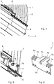
- Figs. 4-6 present the fixing point of the free end of the ribbed reinforcement bars 2a and one possible clamp part 7 in magnified view.
- the fixing is implemented by means of a clamp part 7, with which two ribbed reinforcement bars 2a can be fixed to the steel pipe 1 with the same fixing.
- a rectangularly-shaped aperture 6 is made in the inwardly extending crest of the corrugation of the steel pipe 1, into which aperture the two-part tongue 7c, split in the center by a notch 7d, of the clamp part 7 is pushed and the clamp part 7 is fixed with a bolt-nut joint 8 from the aforementioned aperture 6 to the steel pipe 1.
- the ends of ribbed reinforcement bars 2a bent in advance into the correct curved shape at the factory are fixed, preferably also at the factory, into the notches 7e in the clamp part 7, either by welding or by some other suitable fixing method.
- the thickness and cross-section of the tongue 7c of a clamp part 7 essentially correspond to the height and cross-section of the aperture 6 in such a way that the tongue 7c of the clamp part can be pushed into the aperture 6 when fixing the clamp part 7 into its position.
- the clamp part 7 is a piece bent from steel plate to an angle of 90 degrees, the support parts 7a and tongue 7c on which extend at essentially a right angle in the direction of the rim of the steel pipe 1 and the body part 7b extends obliquely downwards.
- One ribbed reinforcement bar 2a in a trough on both sides of one inward-extending crest can be fixed with the same clamp part 7.
- a ribbed reinforcement bar 2a does not necessarily need to be in all the troughs, so that an aperture 6 does not need to be made in all the crests nor does a clamp part need to be fixed in all the crests.
- the structure of the clamp part 7 and the shape of the aperture 6 can be different to what is presented above. What is important is that the shearing force acting on the fixing is managed in the fixing.
- Figs. 7-9 present a part of one lowermost mold module 3, according to the invention, to be used for the strengthening of a pipe culvert. Normally the mold module 3 would be longer than in the figure, so that in Fig. 7 the mold module 3 is truncated.
- the lowermost mold module 3 is made e.g. from thin steel sheet by bending and by making in it the appropriate perforation. After the perforation and bending the mold module 3 is protected against rust and outdoor use e.g. by coating.
- the lowermost mold module 3 is symmetrical with respect to its center line in cross-section.
- a row of elongated fixing holes 10 for fixing the mold module 3 to the base of the steel pipe 1 e.g. with screw fixings.
- the screws are fixed e.g. to the crests that are on the inside surface of the corrugated steel pipe.
- the apertures 9 allow the concrete to flow to the base of the steel pipe 1 to below the mold module 3.
- Fig. 9 presents the shape of the apertures 9 in more detail.
- the top part 9a of the aperture 9 in the bend 3b is symmetrically wider than the other part of the aperture 9.
- the height of the top part corresponds to the thickness of the protrusions 4f that are on the bottom edge of a middle module 4 and the width of the top part 9a corresponds to the width of the protrusions 4f in such a way that when fixing a middle mold module 4 into its position the protrusions 4f can be disposed in the top parts 9a of the apertures 9 and can be pushed inside them.
- the distribution of the apertures 9 is adapted to correspond to the distribution of the protrusions 4f.
- the protrusions 4f are described in more detail in the description of Figs. 10-12 .
- Figs. 10-12 present a part of one middle mold module 4, according to the invention, to be used for the strengthening of a pipe culvert. Normally the mold module 4 also would be longer than in the figure, so that in Fig. 10 the mold module 4 is truncated.
- a middle mold module 4 is made e.g. from thin steel sheet by bending and by making in it the appropriate perforation. After the perforation and bending the mold module 4 is protected against rust and outdoor use e.g. by coating.
- a middle mold module 4 is asymmetrical with respect to its center line in cross-section. It has a back part 4a provided with a longitudinal directional and stiffening fold 11 in the center, in the first side of which back part, i.e.
- the side to be disposed lower is an almost right-angled bend 4c, on the edge of which is a row of protrusions 4f that are similar to each other extending outwards in an essentially orthogonal direction from the center line, which protrusions are at a distance 4g from each other.
- an almost right-angled bend 4b on the edge of which is again an essentially right-angled bend 4d turning outwards from the center line, on the edge of which bend 3c is again a short essentially right-angled bend 4e towards the planar surface of the back part 4a.
- the middle mold module 4 When the middle mold module 4 is in its position on the inside surface of the steel pipe 1 of a pipe culvert, the aforementioned bends 4b and 4c point towards the inside surface of the steel pipe 1 and the protrusions 4f point towards the next lower mold module 3 or 4.
- the bend 4d points in the direction of the inside surface of the steel pipe 1 towards the next higher mold module 4 or 5
- the bend 4e points at essentially a right angle outwards from the surface of the steel pipe 1.
- the bending 4e functions here also as a stiffener.
- a row of elongated fixing holes 10 for fixing the mold module 4 to the crests of the inside surface of the steel pipe 1 e.g. with screw fixings.
- the fixing holes 10 can also be used for suspending the ribbed reinforcement bars 2a to their correct points off the surface of the troughs of the steel pipe 1.
- the suspending of the ribbed reinforcement bars 2a is done in the manner presented above e.g. with thin iron rods bent into a loop, which are threaded around the bottom of the ribbed reinforcement bars 2a and fixed to the fixing holes 10 in the edge of the lowermost mold module 3, which holes are off the inside surface of the steel pipe 1 at the point of the troughs.
- the apertures 9 allow the concrete to flow through towards the base of the steel pipe 1.
- top parts 9a are wider than the apertures 9, which top parts correspond in their position, size and shape with the corresponding top parts 9a of the apertures 9 of a lowermost mold module 3.
- Fig. 1a presents a middle mold module, which is strengthened on its back part with a row of stiffeners 11a transverse to the mold module 4, instead of with a longitudinal directional and stiffening fold 11, which stiffeners can be e.g. troughs or crests pressed into the back part 4a.
- stiffeners can be e.g. troughs or crests pressed into the back part 4a.
- the mold module 4 withstands the casting pressure in the concrete casting phase better.
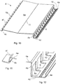
- Figs. 13 and 14 present a part of one uppermost mold module 5, according to the invention, to be used for the strengthening of a pipe culvert. Normally also the mold module 5 would be longer than in the figures, so that in Figs. 13 and 14 the mold module 5 is truncated.
- the uppermost mold module 5 is fabricated in essentially the same way and from the same material as the mold modules 3 and 4 described earlier.
- the uppermost mold module 5 is also asymmetrical with respect to its center line in cross-section. It has a narrow back part 5a, in the first side of which back part, i.e.
- the side to be disposed lower when the mold module 5 is in its position is a bend 5d extending obliquely towards the inside surface of the steel pipe 1, on the edge of which bend 5d is a bend 5e in the direction of the back part 5a, on the edge of which bend 5e is a bend 5f extending at a right angle towards the inside surface of the steel pipe 1, on the edge of which bend 5f is a row of protrusions 5g that are similar to each other and in essentially the direction of the inside surface of the steel pipe 1, which protrusions are at a distance 5h from each other and correspond in their distribution, size and shape with the corresponding protrusions 4f of a middle mold module.
- the second side of the back part 5a i.e. the side to be disposed higher
- an almost right-angled bend 5b on the edge of which is again bend 5c turning at essentially a right angle outwards from the center line, i.e. essentially in the direction of the inside surface of the steel pipe 1
- bend 5c is a row of elongated fixing holes 10 for fixing the mold module 5 to the crests of the inside surface of the steel pipe 1 e.g. with screw fixings.
- the bend 5b forms, when the mold module 5 is in its position, an essentially wide top surface, in which is a row of apertures 12 for casting concrete to inside the mold 2.
- the bend 5b forms, together with the concrete, a planar surface along which e.g. small animals can safely travel to the other side of the accessway that is above.
- the wide bend 5b enables a sufficient protective distance for the clamp parts 7 to be disposed below the mold module 5.
- the aforementioned bend 5c points upwards in the direction of the inside surface of the steel pipe 1 and the protrusions 5g point towards the next lower mold module 4, and also the bend 5d points obliquely downwards towards the inside surface of the steel pipe 1 forming a downward-tapering space for improving the flowing of concrete to inside the mold 2.
- a damaged steel pipe 1 of a pipe culvert is strengthened e.g. as follows: At first the steel pipe 1 and its points of damage, or an undamaged steel pipe 1, to be strengthened is measured and the strengthening procedures are planned. After this the ribbed reinforcement bars 2a needed are cut to their correct dimensions and bent into a curve corresponding to the inside curve of the steel pipe 1. This phase can be performed at the factory or also at the worksite. On the basis of measuring and planning, a suitable number of mold modules 3-5 that are ready in stock or made exactly for this purpose, as well as fixing accessories, are selected and all the parts are transported to the worksite, and the worksite is prepared for the strengthening.
- transverse concrete reinforcements 2b are needed under the steel pipe 1 for additional reinforcement, they are made first. In this case space for the concrete is made e.g. in one of the ways presented in connection with Fig. 1a , or in some other suitable manner. After this the ribbed reinforcement bars 2a are placed into their positions.
- the mold 2 is installed by situating the ribbed reinforcement bars 2a according to plan in the troughs of the corrugated steel pipe 1. After this the necessary amount of lowermost mold modules 3 are fixed consecutively to the base of the steel pipe 1 and, if necessary, ribbed reinforcement bars 2a are suspended on the edges of the mold modules 3 off the inside surface of the steel pipe 1.
- the bottommost middle mold modules 4 are locked at their bottom edges to the side edges of the lowermost mold modules 3 and fixed at their top edges to the inside surface of the steel pipe 1 and, if necessary, ribbed reinforcement bars 2a are suspended on the top edges of the mold modules 4 off the inside surface of the steel pipe 1.
- the next row of middle mold modules 4 are fixed into position in the same way and, if necessary, ribbed reinforcement bars 2a are suspended on the edges of the mold modules 3 off the inside surface of the steel pipe 1.
- the assembly of the mold 2 is continued in this way until the last row of middle mold modules 4 has been fixed into position.
- the free ends of the ribbed reinforcement bars 2a are fixed with clamp parts 7 to the inside surface of the steel pipe 1, if this has not already been done earlier.
- the uppermost mold modules 5 are placed on the top edge of the topmost middle mold modules 4, which uppermost mold modules 5 are fixed at their top edge to the inside surface of the steel pipe 1 in such a way that the top edge of the uppermost mold modules 5 and at the same time the top edge of the mold 2 are situated on both side edges of the steel pipe 1 higher than the damaged area of the steel pipe 1, or in connection with the strengthening of an undamaged steel pipe 1 to their point according to the strengthening plan.
- the second half is fabricated in essentially the same way. Both halves can be assembled also at essentially the same time.
- the mold 2 is ready and the casting is performed by pouring thin, very fluid concrete from the top edge of the mold 2, i.e. from the apertures 12 of the uppermost mold modules 5, into between the inside surface of the bottom part of the steel pipe 1 and the mold 2 in such a way that the ribbed reinforcement bars 2a in the troughs between the crests of the steel pipe 1 are completely covered with concrete. After the concreting has hardened the strengthening is ready.
- the strengthening is performed in essentially the manner described above but omitting the procedures relating to damage points. How high the top edges of the mold 2 are situated on each side wall depends on each specific situation.
- FIGs. 15-17 One method and way for strengthening the whole rim of a steel pipe 1 is presented in Figs. 15-17 , in which the final phase of the installation of a mold 2 in the top part of a steel pipe 1 of a pipe culvert is described.
- an uppermost mold module 13 that is adjustable in its width corresponds to the uppermost mold module 5 mentioned earlier, by means of which mold module 13 the mold 2 to be assembled is closed for casting into an essentially complete rim.
- the uppermost mold module 13 that is adjustable in its width is composed of two main parts that are overlapping each other, i.e.
- Both side parts 13a, 13b have a base part 14a forming at least a part of the base of the uppermost mold module 13, a side wall 14b and extending from the side wall a plurality of protrusions 14c that are side by side each other, which essentially correspond to the protrusions 4f of a middle mold module 4 that were described earlier.
- ribbed reinforcement bars 2a Used as additional strengthening, also, when strengthening the whole steel pipe 1, are ribbed reinforcement bars 2a, which are disposed, before the assembly of the mold 2, in the troughs between the crests of the corrugated steel pipe 1, as described earlier.
- ribbed reinforcement bars 2a When using suitably short ribbed reinforcement bars 2a from the viewpoint of transport and ease of handling, they are continued in the troughs by fixing to each other until a sufficient strengthening length is reached.
- the middle mold modules 4 of the mold 2 are fixed to the inside surface of the steel pipe, as described earlier, rising along both inside edges of the steel pipe 1 and fixing to the steel pipe 1 at their top edge, until the distance between the bend 4b on the side of the mold module 4 to be placed higher of both sides, i.e. fixed from two opposite edges, is smaller than the largest available width of the uppermost module 13 that is adjustable in its width.
- Fig. 16 presents a situation in which the first part 13a of the uppermost mold module 13 that is adjustable in width has been placed into position to be supported by its protrusions 14c in the top parts 9a of the apertures 9 in the side wall 4b of the topmost middle mold module 4 of the first side.
- Fig. 17 presents a situation in which the second part 13b of the uppermost mold module 13 that adjustable in width has been placed into position to be supported by its protrusions 14c in the top parts 9a of the apertures 9 in the side wall 4b of the topmost middle mold module 4 of the second side, and the base part 14a overlapped with the base part 14a of the first part 13a, either above or below the base part 14a of the first part 13a.
- the base parts 14a are fixed to each other with fixing means 15, such as with screws or rivets, in which case the uppermost mold modules 13 form a sufficiently rigid structure in the top part of the mold 2.
- the height of the side walls 14b of the uppermost mold modules 13 are selected in such a way that inside an uppermost mold module 13 fixed into its position is a space having a height so large that a concrete dropchute 16 can be disposed inside the mold module 13, which dropchute can be pulled at a constant speed and at the same time can feed concrete to inside the mold module 13 in such a way that concrete flows also from the apertures 9 of the topmost middle mold modules 4 downwards to inside the mold 2 finally filling the whole of the space between the mold 2 and the inside surface of the steel pipe 1.
- mold modules can also be different to what is presented above.
- the mold modules can be e.g. flexible and transverse to the steel pipe instead of in the longitudinal direction of the steel pipe.
- a mold module could extend from one edge of the steel pipe from above the damage area to the other edge to above the damage area, and when continuing the mold modules they are fixed consecutively to each other in the longitudinal direction of the steel pipe.
Landscapes
- Engineering & Computer Science (AREA)
- General Engineering & Computer Science (AREA)
- Civil Engineering (AREA)
- Structural Engineering (AREA)
- Architecture (AREA)
- Mechanical Engineering (AREA)
- Environmental & Geological Engineering (AREA)
- Life Sciences & Earth Sciences (AREA)
- General Life Sciences & Earth Sciences (AREA)
- Mining & Mineral Resources (AREA)
- Paleontology (AREA)
- Sewage (AREA)
- Bridges Or Land Bridges (AREA)
Claims (18)
- Verfahren zum Verstärken einer Struktur einer Röhrenbrücke oder eines Durchlasses, wobei die Struktur mindestens ein gewelltes Stahlrohr (1) umfasst, das das zu verstärkende Objekt ist und das mit einer inneren Oberfläche versehen ist, und wobei in dem Verfahren ein oder mehrere Verstärkungselemente in Verbindung mit dem unteren Teil des Stahlrohres (1) angeordnet werden, dadurch gekennzeichnet, dass als Verstärkungselemente gerippte Verstärkungsstäbe (2a) in Mulden des gewellten Stahlrohres (1) angeordnet werden, und dass zumindest oben auf der inneren Oberfläche des unteren Teils des Stahlrohres (1) und oben auf den gerippten Verstärkungsstäben (2a) eine Form (2) befestigt wird, die aus Formmodulen (3-5, 13) zusammengesetzt wird, die nebeneinander und/oder aufeinanderfolgend verlaufen, woraufhin der Raum zwischen der inneren Oberfläche des Stahlrohres (1) und der Form (2) mit Beton gefüllt wird.
- Verfahren gemäß Anspruch 1, dadurch gekennzeichnet, dass eine aus gerippten Verstärkungsstäben (2a), die als Verstärkungselemente wirken, gebildete Betonverstärkung in Mulden der inneren Oberfläche des unteren Teils des Stahlrohres (1) und in Verbindung mit dem Verstärken eines beschädigten Stahlrohres (1) auch oben auf beschädigten Flächen montiert wird, wobei oben auf der Betonverstärkung eine Form (2), die aus Formmodulen (3-5, 13) gebildet wird, angeordnet wird, woraufhin der Raum zwischen der inneren Oberfläche des Stahlrohres (1) und der Form (2) mit Beton in einer solchen Art und Weise gefüllt wird, dass die gerippten Verstärkungsstäbe (2a) im Wesentlichen vollständig mit Beton bedeckt bleiben und ebenso in Zusammenhang mit der Reparatur eines beschädigten Stahlrohres (1) auch die Schadensflächen im Wesentlichen vollständig mit Beton bedeckt bleiben.
- Verfahren gemäß Anspruch 1 oder 2, dadurch gekennzeichnet, dass die Form (2) aus Formmodulen (3-5) zusammengesetzt wird, die im Wesentlichen konstante Breiten und konstante Längen aufweisen und in der Längsrichtung des Stahlrohres (1) orientiert sind, wobei die untersten Formmodule (3) der Formmodule an der inneren Oberfläche des Stahlrohres (1) im Wesentlichen der Mitte der Basis des Stahlrohres (1) befestigt werden, und die nächsten, d. h. die mittleren, Formmodule (4) der Formmodule an ihrer ersten Kante zu der Seitenkante des untersten Formmodules (3) verriegelt werden, wobei die besagten mittleren Module dann an ihrer zweiten Kante an der inneren Oberfläche des Stahlrohres (1) befestigt sind, wobei die nächsten mittleren Formmodule (4) der Formmodule an ihrer ersten Kante zu der zweiten Kante der mittleren Formmodule (4) verriegelt werden, wobei die besagten nächsten mittleren Module dann an ihrer zweiten Kante an der inneren Oberfläche des Stahlrohres (1) weiter befestigt sind, und dies fortgesetzt wird, bis die sämtlichen mittleren Formmodule (4) in ihren Positionen befestigt sind, woraufhin die obersten Formmodule (5) an ihrem unteren Rand zu der oberen Kante der obersten mittleren Formmodule (4) befestigt werden, wobei die besagten obersten Formmodule dann an ihrer oberen Kante an der inneren Oberfläche des Stahlrohres (1) befestigt sind, um die obere Kante der Form (2) zu bilden.
- Verfahren gemäß Anspruch 1 oder 2, dadurch gekennzeichnet, dass die Form (2) aus Formmodulen (3, 4, 13) zusammengesetzt wird, die im Wesentlichen konstante Breiten und konstante Längen aufweisen und in der Längsrichtung des Stahlrohres (1) orientiert sind, wobei die untersten Formmodule (3) der Formmodule an der inneren Oberfläche des Stahlrohres (1) in im Wesentlichen der Mitte der Basis des Stahlrohres (1) befestigt werden und die nächsten, d. h. mittleren, Formmodule (4) der Formmodule an ihrer ersten Kante zu der Seitenkante der untersten Formmodule (3) verriegelt werden, wobei die besagten mittleren Module dann an ihrer zweiten Kante an der inneren Oberfläche des Stahlrohres (1) befestigt sind, wobei die nächsten mittleren Formmodule (4) der Formmodule an ihrer ersten Kante zu der zweiten Kante der mittleren Formmodule (4) verriegelt werden, wobei die nächsten mittleren Module dann an ihrer zweiten Kante zu der inneren Oberfläche des Stahlrohres (1) befestigt sind, und dies fortgesetzt wird, bis die sämtlichen mittleren Formmodule (4) in ihren Positionen befestigt sind, woraufhin die obersten Formmodule (13), die in ihrer Breite verstellbar sind, auf der oberen Kante der obersten mittleren Formmodule (4) gestützt werden, um den oberen Teil der Form (2) zu bilden.
- Verfahren gemäß irgendeinem der vorhergehenden Ansprüche, dadurch gekennzeichnet, dass die obere Kante der obersten Formmodule (5) und zugleich die obere Kante der Form (2) auf beiden Kanten des Stahlrohres (1) aufliegen, um höher zu sein als die beschädigte Fläche des Stahlrohres (1).
- Verfahren gemäß irgendeinem der vorhergehenden Ansprüche, dadurch gekennzeichnet, dass die gerippten Verstärkungsstäbe (2a), die die Betonverstärkung bilden, zwischen die innere Oberfläche des Stahlrohres (1) und die Form (2) in solch einer Art und Weise angeordnet werden, dass die gerippten Verstärkungsstäbe (2a) von der inneren Oberfläche des Stahlrohres (1) weg angeordnet sind.
- Verfahren gemäß irgendeinem der vorhergehenden Ansprüche, dadurch gekennzeichnet, dass die gerippten Verstärkungsstäbe (2a), die die Betonverstärkung bilden, an den Seitenkanten der untersten Formelemente (3) und/oder an den oberen Kanten der mittleren Formelemente (4) aufgehängt werden, um die gerippten Verstärkungsstäbe (2a) von der inneren Oberfläche des Stahlrohres (1) fernzuhalten.
- Verfahren gemäß irgendeinem der vorhergehenden Ansprüche, dadurch gekennzeichnet, dass die gerippten Verstärkungsstäbe (2a) an ihren freien Enden an der inneren Oberfläche des Stahlrohres (1) oberhalb der Schadensfläche des Stahlrohres (1) befestigt werden.
- Verfahren gemäß irgendeinem der vorhergehenden Ansprüche, dadurch gekennzeichnet, dass das Stahlrohr (1) mit gekrümmten zusätzlichen Betonverstärkungen (2b) verstärkt wird, die als Verstärkungselemente wirken und in Verbindung mit dem unteren Teil des Stahlrohres (1) unter der Form (2) angeordnet sind, wobei die Betonverstärkungen quer zu dem Stahlrohr (1) in den erforderlichen Intervallen in der Längsrichtung des Stahlrohres (1) angeordnet werden.
- Röhrenbrücke oder Durchlass, wobei eine Struktur davon zumindest ein gewelltes Stahlrohr (1) umfasst, das das zu verstärkende Objekt ist und das mit einer inneren Oberfläche versehen ist, wobei in der Röhrenbrücke oder dem Durchlass ein oder mehrere Verstärkungselemente in Verbindung mit dem unteren Teil des Stahlrohres (1) montiert sind, dadurch gekennzeichnet, dass in Mulden des gewellten Stahlrohres (1) gerippte Verstärkungsstäbe (2a) als Verstärkungselemente angeordnet sind, und dass zumindest eine Form (2) oben auf der inneren Oberfläche des unteren Teils des Stahlrohres (1) und den gerippten Verstärkungsstäben (2a) befestigt ist, wobei die Form (2) aus Formmodulen (3-5, 13) zusammengesetzt ist, die nebeneinander und/oder aufeinanderfolgend verlaufen, und dass der Raum zwischen der inneren Oberfläche des Stahlrohres (1) und der Form (2) mit Beton gefüllt sind.
- Röhrenbrücke oder Durchlass gemäß Anspruch 10, dadurch gekennzeichnet, dass eine Betonverstärkung, die aus gerippten Verstärkungsstäben (2a) gebildet ist, auf der inneren Oberfläche des unteren Teils des Stahlrohres (1) und in Verbindung mit dem Verstärken eines geschädigten Stahlrohres (1) auch oben auf beschädigten Flächen angeordnet ist, wobei oben auf der Verstärkung eine Form (2), die aus Formmodulen (3-5, 13) gebildet ist, angeordnet ist, und dass der Raum zwischen der inneren Oberfläche des Stahlrohres (1) und der Form (2) in solch einer Art und Weise mit Beton gefüllt ist, dass die Schadensflächen und die gerippten Verstärkungsstäbe (2a) im Wesentlichen vollständig vom Beton bedeckt sind.
- Röhrenbrücke und Durchlass gemäß Anspruch 10 oder 11, dadurch gekennzeichnet, dass die Form (2) aus Formmodulen (3-5) gebildet sind, die im Wesentlichen konstante Breiten und konstante Längen aufweisen und die in der Längsrichtung des Stahlrohres (1) orientiert sind, wobei die untersten Formmodule (3) der Formmodule an der inneren Oberfläche des Stahlrohres (1) in im Wesentlichen der Mitte der Basis des Stahlrohres (1) befestigt sind und an beiden Seiten der untersten Formmodule (3) eine oder mehrere Reihen mittlerer Formmodule (4) angeordnet sind, die an ihrer unteren Kante zu der vorherigen Reihe von Formmodulen (3 oder 4) verriegelt sind und an ihrer oberen Kante an der inneren Oberfläche des Stahlrohres (1) befestigt sind, und dass die oberste Reihe auf beiden Seiten der Form (2) eine Reihe oberster Formmodule (5) ist, die an ihrer oberen Kante an der inneren Oberfläche des Stahlrohres (1) befestigt sind, um die obere Kante der Form (2) zu bilden.
- Röhrenbrücke oder Durchlass gemäß Anspruch 10 oder 11, dadurch gekennzeichnet, dass die Form (2) aus Formmodulen (3, 4, 13) gebildet ist, die im Wesentlichen konstante Breiten und konstante Längen aufweisen und die in der Längsrichtung des Stahlrohres (1) orientiert sind, wobei die untersten Formmodule (3) der Formmodule an der inneren Oberfläche des Stahlrohres (1) in im Wesentlichen der Mitte der Basis des Stahlrohres (1) befestigt sind und an beiden Seiten der untersten Formmodule (3) eine oder mehrere Reihen von mittleren Formmodulen (4) angeordnet sind, die an ihrer unteren Kante zu der vorherigen Reihe von Formmodulen (3 oder 4) verriegelt sind und an ihrer oberen Kante an der inneren Oberfläche des Stahlrohres (1) befestigt sind, und dass die oberste Reihe in der Form (2) eine Reihe von obersten Formmodulen (13) ist, die in ihrer Breite einstellbar sind, wobei die obersten Formmodule eingerichtet sind, um auf der oberen Kante der obersten mittleren Formmodule (4) zu ruhen, um den oberen Teil der der Form (2) zu bilden.
- Röhrenbrücke oder Durchlass gemäß irgendeinem der vorhergehenden Ansprüche 10-13, dadurch gekennzeichnet, dass die obere Kante der obersten Formmodule (5, 13) und zugleich die obere Kante der Form (2) auf beiden Seitenkanten des Stahlrohres (1) höher sind als die beschädigte Fläche des Stahlrohres (1).
- Röhrenbrücke oder Durchlass gemäß irgendeinem der vorhergehenden Ansprüche 10-14, dadurch gekennzeichnet, dass die gerippten Verstärkungsstäbe (2a), die die Betonverstärkung bilden, zwischen der inneren Oberfläche des Stahlrohres (1) und der Form (2) angeordnet sind und an den Seitenkanten der untersten Formelemente (3) und/oder an den oberen Kanten der mittleren Formelemente (4) in solch einer Art und Weise aufgehängt sind, dass die gerippten Verstärkungsstäbe (2a) von der inneren Oberfläche des Stahlrohres (1) weg angeordnet sind.
- Röhrenbrücke oder Durchlass gemäß irgendeinem der vorhergehenden Ansprüche 10-15, dadurch gekennzeichnet, dass die gerippten Verstärkungsstäbe (2a) an ihren freien Enden an der inneren Oberfläche des Stahlrohres (1) oberhalb der Schadensflächen des Stahlrohres (1) befestigt sind.
- Röhrenbrücke oder Durchlass gemäß irgendeinem der vorhergehenden Ansprüche 10-16, dadurch gekennzeichnet, dass das gewellte Stahlrohr (1) in der radialen Richtung sich nach innen erstreckende Kämme und nach außen erstreckende Mulden umfasst, und dass die Formmodule (3-5) an Kämmen der inneren Oberfläche des Stahlrohres (1) oben auf den gerippten Verstärkungsstäben (2a) befestigt sind und die gerippten Verstärkungsstäbe (2a) an der Stelle der Mulden weg von der inneren Oberfläche des Stahlrohres (1) und weg von den Formmodulen (3-5, 13) angeordnet sind.
- Röhrenbrücke oder Durchlass gemäß irgendeinem der vorhergehenden Ansprüche 10-17, dadurch gekennzeichnet, dass das Stahlrohr (1) mit gekrümmten zusätzlichen Betonverstärkungen (2b) verstärkt ist, die als Verstärkungselemente wirken und in Verbindung mit dem unteren Teil des Stahlrohres (1) unter der Form (2) angeordnet sind, wobei die Betonverstärkungen quer zu dem Stahlrohr (1) in den erforderlichen Intervallen in der Längsrichtung des Stahlrohres (1) angeordnet sind.
Priority Applications (1)
| Application Number | Priority Date | Filing Date | Title |
|---|---|---|---|
| PL14860327T PL3066262T4 (pl) | 2013-11-06 | 2014-11-03 | Sposób wzmocnienia konstrukcji mostu rurowego lub przepustu i wzmocnienie mostu rurowego lub przepustu |
Applications Claiming Priority (2)
| Application Number | Priority Date | Filing Date | Title |
|---|---|---|---|
| FI20136096A FI127161B (fi) | 2013-11-06 | 2013-11-06 | Menetelmä putkisillan tai alitusputken rakenteen vahvistamiseksi ja vahvistettu putkisilta tai alitusputki |
| PCT/FI2014/050823 WO2015067851A1 (en) | 2013-11-06 | 2014-11-03 | Method for strengthening a structure of a tubular bridge or a culvert and the strengthened tubular bridge or culvert |
Publications (3)
| Publication Number | Publication Date |
|---|---|
| EP3066262A1 EP3066262A1 (de) | 2016-09-14 |
| EP3066262A4 EP3066262A4 (de) | 2016-11-23 |
| EP3066262B1 true EP3066262B1 (de) | 2019-01-09 |
Family
ID=53040953
Family Applications (1)
| Application Number | Title | Priority Date | Filing Date |
|---|---|---|---|
| EP14860327.7A Active EP3066262B1 (de) | 2013-11-06 | 2014-11-03 | Verfahren zur verstärkung einer struktur einer röhrenförmigen brücke oder eines kanals und verstärkte rohrförmige brücke oder kanal |
Country Status (5)
| Country | Link |
|---|---|
| EP (1) | EP3066262B1 (de) |
| DK (1) | DK3066262T3 (de) |
| FI (1) | FI127161B (de) |
| PL (1) | PL3066262T4 (de) |
| WO (1) | WO2015067851A1 (de) |
Families Citing this family (1)
| Publication number | Priority date | Publication date | Assignee | Title |
|---|---|---|---|---|
| CN112681160B (zh) * | 2020-12-23 | 2022-07-29 | 浙江世润建创科技发展有限公司 | 钢筋混凝土拱涵增大截面加固结构及施工方法 |
Family Cites Families (9)
| Publication number | Priority date | Publication date | Assignee | Title |
|---|---|---|---|---|
| US1929817A (en) * | 1931-05-08 | 1933-10-10 | Helsing J Linus | Culvert |
| US2081872A (en) * | 1937-02-19 | 1937-05-25 | Republic Steel Corp | Culvert |
| US2290791A (en) * | 1940-05-14 | 1942-07-21 | John L Young | Reinforced protection for culverts |
| AT363855B (de) * | 1977-06-03 | 1981-09-10 | Krems Huette Gmbh | Verfahren zum herstellen eines durchlassbauwerkes |
| US6703091B1 (en) * | 1999-04-16 | 2004-03-09 | Roger H. Walker | Structural lining system for pipes and method for applying same |
| JP2005232954A (ja) * | 2004-01-20 | 2005-09-02 | Yoshiji Matsumoto | コンクリート構造物の補強部材およびコンクリート構造物の補強工法 |
| SE531827C2 (sv) * | 2007-12-12 | 2009-08-18 | Wbf Invest Ab | Metod för manuell renovering av ett inre ytskikt i ett korrugerat stålrör |
| US8096730B1 (en) * | 2008-05-06 | 2012-01-17 | Alan Hollis | Apparatus for laying concrete metal pipes inverts and method for using the same |
| US8418336B2 (en) * | 2009-07-07 | 2013-04-16 | Roger Michael Bennett | Method and system for repairing the flow-line of corrugated metal pipes |
-
2013
- 2013-11-06 FI FI20136096A patent/FI127161B/fi active IP Right Grant
-
2014
- 2014-11-03 PL PL14860327T patent/PL3066262T4/pl unknown
- 2014-11-03 EP EP14860327.7A patent/EP3066262B1/de active Active
- 2014-11-03 DK DK14860327.7T patent/DK3066262T3/en active
- 2014-11-03 WO PCT/FI2014/050823 patent/WO2015067851A1/en not_active Ceased
Non-Patent Citations (1)
| Title |
|---|
| None * |
Also Published As
| Publication number | Publication date |
|---|---|
| PL3066262T4 (pl) | 2020-01-31 |
| PL3066262T3 (pl) | 2019-10-31 |
| FI127161B (fi) | 2017-12-29 |
| DK3066262T3 (en) | 2019-04-23 |
| EP3066262A4 (de) | 2016-11-23 |
| WO2015067851A1 (en) | 2015-05-14 |
| FI20136096A7 (fi) | 2015-05-07 |
| EP3066262A1 (de) | 2016-09-14 |
Similar Documents
| Publication | Publication Date | Title |
|---|---|---|
| KR20140047118A (ko) | 교량을 위한 기초 시스템 | |
| CN109594663B (zh) | 用于后浇带位置的钢筋混凝土诱导带结构及其施工方法 | |
| KR101344063B1 (ko) | 강합성 지하차도 시공 공법 | |
| KR101228593B1 (ko) | 내부중공재를 이용한 합성거더 및 이를 이용한 교량 시공방법 | |
| CN100482993C (zh) | 使用管架组件对管道和综合管路的铺设方法 | |
| US11174614B2 (en) | Metal foundation system for culverts, buried bridges and other structures | |
| CN110468831A (zh) | 桥梁桩基现绑钢筋笼偏位控制模架及其施工方法 | |
| EP3066262B1 (de) | Verfahren zur verstärkung einer struktur einer röhrenförmigen brücke oder eines kanals und verstärkte rohrförmige brücke oder kanal | |
| KR101054718B1 (ko) | 부벽과 긴장재를 이용한 라멘구조물 및 그 시공방법 | |
| US5904185A (en) | Conduit for the circulation of fluid | |
| KR101788581B1 (ko) | 우각부가 보강된 교량 시공방법 및 이러한 시공방법으로 제작되는 교량 | |
| KR101081840B1 (ko) | 콘크리트와 함께 일체로 매립된 지주를 이용하여 인도의 폭을 확장시킬 수 있는 사면 가설인도의 설치공법 | |
| JP2019151999A (ja) | 防液堤の施工方法、及び防液堤 | |
| KR20040001642A (ko) | 파형강판을 이용한 터널의 라이닝 시공방법 | |
| KR20030094195A (ko) | 개량된 프리스트레스트 철골 철근 콘크리트 빔 및 이를이용한 교량 시공방법 | |
| CN209837333U (zh) | 用于后浇带位置的钢筋混凝土诱导带结构 | |
| JP7094526B1 (ja) | 法面排水設備の壁状構造体 | |
| KR100902640B1 (ko) | 강널말뚝을 이용한 수로암거 및 그 시공방법 | |
| KR102206777B1 (ko) | 개구형 단경간 강합성 거더 및 이의 제작방법 | |
| CN110374012A (zh) | 一种t梁原位支架法预制工法 | |
| JP2016166498A (ja) | 壁体構築方法および壁体 | |
| CN210658450U (zh) | 一种地下结构双面叠合剪力外墙板止水钢板固定结构 | |
| CN116815662A (zh) | 钢波纹棚洞施工方法 | |
| JP6232190B2 (ja) | 目地構成部材、コンクリート打設方法、コンクリート構造物 | |
| KR101047943B1 (ko) | 보강설비가 구비된 확장인도 및 그 시공방법 |
Legal Events
| Date | Code | Title | Description |
|---|---|---|---|
| PUAI | Public reference made under article 153(3) epc to a published international application that has entered the european phase |
Free format text: ORIGINAL CODE: 0009012 |
|
| 17P | Request for examination filed |
Effective date: 20160602 |
|
| AK | Designated contracting states |
Kind code of ref document: A1 Designated state(s): AL AT BE BG CH CY CZ DE DK EE ES FI FR GB GR HR HU IE IS IT LI LT LU LV MC MK MT NL NO PL PT RO RS SE SI SK SM TR |
|
| AX | Request for extension of the european patent |
Extension state: BA ME |
|
| A4 | Supplementary search report drawn up and despatched |
Effective date: 20161026 |
|
| RIC1 | Information provided on ipc code assigned before grant |
Ipc: E01D 22/00 20060101AFI20161020BHEP Ipc: E04G 23/02 20060101ALI20161020BHEP Ipc: E02D 29/067 20060101ALI20161020BHEP |
|
| DAX | Request for extension of the european patent (deleted) | ||
| STAA | Information on the status of an ep patent application or granted ep patent |
Free format text: STATUS: EXAMINATION IS IN PROGRESS |
|
| 17Q | First examination report despatched |
Effective date: 20170726 |
|
| GRAP | Despatch of communication of intention to grant a patent |
Free format text: ORIGINAL CODE: EPIDOSNIGR1 |
|
| STAA | Information on the status of an ep patent application or granted ep patent |
Free format text: STATUS: GRANT OF PATENT IS INTENDED |
|
| INTG | Intention to grant announced |
Effective date: 20180622 |
|
| GRAS | Grant fee paid |
Free format text: ORIGINAL CODE: EPIDOSNIGR3 |
|
| GRAA | (expected) grant |
Free format text: ORIGINAL CODE: 0009210 |
|
| STAA | Information on the status of an ep patent application or granted ep patent |
Free format text: STATUS: THE PATENT HAS BEEN GRANTED |
|
| AK | Designated contracting states |
Kind code of ref document: B1 Designated state(s): AL AT BE BG CH CY CZ DE DK EE ES FI FR GB GR HR HU IE IS IT LI LT LU LV MC MK MT NL NO PL PT RO RS SE SI SK SM TR |
|
| REG | Reference to a national code |
Ref country code: GB Ref legal event code: FG4D |
|
| REG | Reference to a national code |
Ref country code: CH Ref legal event code: EP Ref country code: AT Ref legal event code: REF Ref document number: 1087447 Country of ref document: AT Kind code of ref document: T Effective date: 20190115 |
|
| REG | Reference to a national code |
Ref country code: IE Ref legal event code: FG4D |
|
| REG | Reference to a national code |
Ref country code: DE Ref legal event code: R096 Ref document number: 602014039770 Country of ref document: DE |
|
| REG | Reference to a national code |
Ref country code: NO Ref legal event code: T2 Effective date: 20190109 Ref country code: DK Ref legal event code: T3 Effective date: 20190415 |
|
| REG | Reference to a national code |
Ref country code: SE Ref legal event code: TRGR |
|
| REG | Reference to a national code |
Ref country code: NL Ref legal event code: MP Effective date: 20190109 |
|
| REG | Reference to a national code |
Ref country code: LT Ref legal event code: MG4D |
|
| PG25 | Lapsed in a contracting state [announced via postgrant information from national office to epo] |
Ref country code: NL Free format text: LAPSE BECAUSE OF FAILURE TO SUBMIT A TRANSLATION OF THE DESCRIPTION OR TO PAY THE FEE WITHIN THE PRESCRIBED TIME-LIMIT Effective date: 20190109 |
|
| REG | Reference to a national code |
Ref country code: AT Ref legal event code: MK05 Ref document number: 1087447 Country of ref document: AT Kind code of ref document: T Effective date: 20190109 |
|
| PG25 | Lapsed in a contracting state [announced via postgrant information from national office to epo] |
Ref country code: ES Free format text: LAPSE BECAUSE OF FAILURE TO SUBMIT A TRANSLATION OF THE DESCRIPTION OR TO PAY THE FEE WITHIN THE PRESCRIBED TIME-LIMIT Effective date: 20190109 Ref country code: LT Free format text: LAPSE BECAUSE OF FAILURE TO SUBMIT A TRANSLATION OF THE DESCRIPTION OR TO PAY THE FEE WITHIN THE PRESCRIBED TIME-LIMIT Effective date: 20190109 Ref country code: FI Free format text: LAPSE BECAUSE OF FAILURE TO SUBMIT A TRANSLATION OF THE DESCRIPTION OR TO PAY THE FEE WITHIN THE PRESCRIBED TIME-LIMIT Effective date: 20190109 Ref country code: PT Free format text: LAPSE BECAUSE OF FAILURE TO SUBMIT A TRANSLATION OF THE DESCRIPTION OR TO PAY THE FEE WITHIN THE PRESCRIBED TIME-LIMIT Effective date: 20190509 |
|
| PG25 | Lapsed in a contracting state [announced via postgrant information from national office to epo] |
Ref country code: BG Free format text: LAPSE BECAUSE OF FAILURE TO SUBMIT A TRANSLATION OF THE DESCRIPTION OR TO PAY THE FEE WITHIN THE PRESCRIBED TIME-LIMIT Effective date: 20190409 Ref country code: IS Free format text: LAPSE BECAUSE OF FAILURE TO SUBMIT A TRANSLATION OF THE DESCRIPTION OR TO PAY THE FEE WITHIN THE PRESCRIBED TIME-LIMIT Effective date: 20190509 Ref country code: LV Free format text: LAPSE BECAUSE OF FAILURE TO SUBMIT A TRANSLATION OF THE DESCRIPTION OR TO PAY THE FEE WITHIN THE PRESCRIBED TIME-LIMIT Effective date: 20190109 Ref country code: RS Free format text: LAPSE BECAUSE OF FAILURE TO SUBMIT A TRANSLATION OF THE DESCRIPTION OR TO PAY THE FEE WITHIN THE PRESCRIBED TIME-LIMIT Effective date: 20190109 Ref country code: HR Free format text: LAPSE BECAUSE OF FAILURE TO SUBMIT A TRANSLATION OF THE DESCRIPTION OR TO PAY THE FEE WITHIN THE PRESCRIBED TIME-LIMIT Effective date: 20190109 Ref country code: GR Free format text: LAPSE BECAUSE OF FAILURE TO SUBMIT A TRANSLATION OF THE DESCRIPTION OR TO PAY THE FEE WITHIN THE PRESCRIBED TIME-LIMIT Effective date: 20190410 |
|
| REG | Reference to a national code |
Ref country code: DE Ref legal event code: R097 Ref document number: 602014039770 Country of ref document: DE |
|
| PG25 | Lapsed in a contracting state [announced via postgrant information from national office to epo] |
Ref country code: CZ Free format text: LAPSE BECAUSE OF FAILURE TO SUBMIT A TRANSLATION OF THE DESCRIPTION OR TO PAY THE FEE WITHIN THE PRESCRIBED TIME-LIMIT Effective date: 20190109 Ref country code: AL Free format text: LAPSE BECAUSE OF FAILURE TO SUBMIT A TRANSLATION OF THE DESCRIPTION OR TO PAY THE FEE WITHIN THE PRESCRIBED TIME-LIMIT Effective date: 20190109 Ref country code: RO Free format text: LAPSE BECAUSE OF FAILURE TO SUBMIT A TRANSLATION OF THE DESCRIPTION OR TO PAY THE FEE WITHIN THE PRESCRIBED TIME-LIMIT Effective date: 20190109 Ref country code: SK Free format text: LAPSE BECAUSE OF FAILURE TO SUBMIT A TRANSLATION OF THE DESCRIPTION OR TO PAY THE FEE WITHIN THE PRESCRIBED TIME-LIMIT Effective date: 20190109 Ref country code: AT Free format text: LAPSE BECAUSE OF FAILURE TO SUBMIT A TRANSLATION OF THE DESCRIPTION OR TO PAY THE FEE WITHIN THE PRESCRIBED TIME-LIMIT Effective date: 20190109 Ref country code: EE Free format text: LAPSE BECAUSE OF FAILURE TO SUBMIT A TRANSLATION OF THE DESCRIPTION OR TO PAY THE FEE WITHIN THE PRESCRIBED TIME-LIMIT Effective date: 20190109 Ref country code: IT Free format text: LAPSE BECAUSE OF FAILURE TO SUBMIT A TRANSLATION OF THE DESCRIPTION OR TO PAY THE FEE WITHIN THE PRESCRIBED TIME-LIMIT Effective date: 20190109 |
|
| PLBE | No opposition filed within time limit |
Free format text: ORIGINAL CODE: 0009261 |
|
| STAA | Information on the status of an ep patent application or granted ep patent |
Free format text: STATUS: NO OPPOSITION FILED WITHIN TIME LIMIT |
|
| PG25 | Lapsed in a contracting state [announced via postgrant information from national office to epo] |
Ref country code: SM Free format text: LAPSE BECAUSE OF FAILURE TO SUBMIT A TRANSLATION OF THE DESCRIPTION OR TO PAY THE FEE WITHIN THE PRESCRIBED TIME-LIMIT Effective date: 20190109 |
|
| 26N | No opposition filed |
Effective date: 20191010 |
|
| PG25 | Lapsed in a contracting state [announced via postgrant information from national office to epo] |
Ref country code: SI Free format text: LAPSE BECAUSE OF FAILURE TO SUBMIT A TRANSLATION OF THE DESCRIPTION OR TO PAY THE FEE WITHIN THE PRESCRIBED TIME-LIMIT Effective date: 20190109 |
|
| PG25 | Lapsed in a contracting state [announced via postgrant information from national office to epo] |
Ref country code: TR Free format text: LAPSE BECAUSE OF FAILURE TO SUBMIT A TRANSLATION OF THE DESCRIPTION OR TO PAY THE FEE WITHIN THE PRESCRIBED TIME-LIMIT Effective date: 20190109 |
|
| REG | Reference to a national code |
Ref country code: CH Ref legal event code: PL |
|
| PG25 | Lapsed in a contracting state [announced via postgrant information from national office to epo] |
Ref country code: MC Free format text: LAPSE BECAUSE OF FAILURE TO SUBMIT A TRANSLATION OF THE DESCRIPTION OR TO PAY THE FEE WITHIN THE PRESCRIBED TIME-LIMIT Effective date: 20190109 Ref country code: LU Free format text: LAPSE BECAUSE OF NON-PAYMENT OF DUE FEES Effective date: 20191103 Ref country code: LI Free format text: LAPSE BECAUSE OF NON-PAYMENT OF DUE FEES Effective date: 20191130 Ref country code: CH Free format text: LAPSE BECAUSE OF NON-PAYMENT OF DUE FEES Effective date: 20191130 |
|
| REG | Reference to a national code |
Ref country code: BE Ref legal event code: MM Effective date: 20191130 |
|
| PG25 | Lapsed in a contracting state [announced via postgrant information from national office to epo] |
Ref country code: IE Free format text: LAPSE BECAUSE OF NON-PAYMENT OF DUE FEES Effective date: 20191103 Ref country code: FR Free format text: LAPSE BECAUSE OF NON-PAYMENT OF DUE FEES Effective date: 20191130 |
|
| PG25 | Lapsed in a contracting state [announced via postgrant information from national office to epo] |
Ref country code: BE Free format text: LAPSE BECAUSE OF NON-PAYMENT OF DUE FEES Effective date: 20191130 |
|
| PG25 | Lapsed in a contracting state [announced via postgrant information from national office to epo] |
Ref country code: CY Free format text: LAPSE BECAUSE OF FAILURE TO SUBMIT A TRANSLATION OF THE DESCRIPTION OR TO PAY THE FEE WITHIN THE PRESCRIBED TIME-LIMIT Effective date: 20190109 |
|
| PG25 | Lapsed in a contracting state [announced via postgrant information from national office to epo] |
Ref country code: MT Free format text: LAPSE BECAUSE OF FAILURE TO SUBMIT A TRANSLATION OF THE DESCRIPTION OR TO PAY THE FEE WITHIN THE PRESCRIBED TIME-LIMIT Effective date: 20190109 Ref country code: HU Free format text: LAPSE BECAUSE OF FAILURE TO SUBMIT A TRANSLATION OF THE DESCRIPTION OR TO PAY THE FEE WITHIN THE PRESCRIBED TIME-LIMIT; INVALID AB INITIO Effective date: 20141103 |
|
| PG25 | Lapsed in a contracting state [announced via postgrant information from national office to epo] |
Ref country code: MK Free format text: LAPSE BECAUSE OF FAILURE TO SUBMIT A TRANSLATION OF THE DESCRIPTION OR TO PAY THE FEE WITHIN THE PRESCRIBED TIME-LIMIT Effective date: 20190109 |
|
| PGFP | Annual fee paid to national office [announced via postgrant information from national office to epo] |
Ref country code: GB Payment date: 20221125 Year of fee payment: 9 Ref country code: DK Payment date: 20221122 Year of fee payment: 9 Ref country code: DE Payment date: 20221123 Year of fee payment: 9 |
|
| PGFP | Annual fee paid to national office [announced via postgrant information from national office to epo] |
Ref country code: PL Payment date: 20221102 Year of fee payment: 9 |
|
| REG | Reference to a national code |
Ref country code: DE Ref legal event code: R119 Ref document number: 602014039770 Country of ref document: DE |
|
| REG | Reference to a national code |
Ref country code: DK Ref legal event code: EBP Effective date: 20231130 |
|
| GBPC | Gb: european patent ceased through non-payment of renewal fee |
Effective date: 20231103 |
|
| PG25 | Lapsed in a contracting state [announced via postgrant information from national office to epo] |
Ref country code: DE Free format text: LAPSE BECAUSE OF NON-PAYMENT OF DUE FEES Effective date: 20240601 |
|
| PG25 | Lapsed in a contracting state [announced via postgrant information from national office to epo] |
Ref country code: DK Free format text: LAPSE BECAUSE OF NON-PAYMENT OF DUE FEES Effective date: 20231130 |
|
| PG25 | Lapsed in a contracting state [announced via postgrant information from national office to epo] |
Ref country code: GB Free format text: LAPSE BECAUSE OF NON-PAYMENT OF DUE FEES Effective date: 20231103 |
|
| PG25 | Lapsed in a contracting state [announced via postgrant information from national office to epo] |
Ref country code: GB Free format text: LAPSE BECAUSE OF NON-PAYMENT OF DUE FEES Effective date: 20231103 Ref country code: DK Free format text: LAPSE BECAUSE OF NON-PAYMENT OF DUE FEES Effective date: 20231130 Ref country code: DE Free format text: LAPSE BECAUSE OF NON-PAYMENT OF DUE FEES Effective date: 20240601 |
|
| PG25 | Lapsed in a contracting state [announced via postgrant information from national office to epo] |
Ref country code: PL Free format text: LAPSE BECAUSE OF NON-PAYMENT OF DUE FEES Effective date: 20231103 |
|
| PGFP | Annual fee paid to national office [announced via postgrant information from national office to epo] |
Ref country code: NO Payment date: 20250602 Year of fee payment: 11 |
|
| PGFP | Annual fee paid to national office [announced via postgrant information from national office to epo] |
Ref country code: SE Payment date: 20250530 Year of fee payment: 11 |