EP3066254B1 - Flusensammelsystem für einen trockner - Google Patents
Flusensammelsystem für einen trockner Download PDFInfo
- Publication number
- EP3066254B1 EP3066254B1 EP14860690.8A EP14860690A EP3066254B1 EP 3066254 B1 EP3066254 B1 EP 3066254B1 EP 14860690 A EP14860690 A EP 14860690A EP 3066254 B1 EP3066254 B1 EP 3066254B1
- Authority
- EP
- European Patent Office
- Prior art keywords
- auger
- lint
- filter housing
- operable
- drive
- Prior art date
- Legal status (The legal status is an assumption and is not a legal conclusion. Google has not performed a legal analysis and makes no representation as to the accuracy of the status listed.)
- Active
Links
Images


Classifications
-
- D—TEXTILES; PAPER
- D06—TREATMENT OF TEXTILES OR THE LIKE; LAUNDERING; FLEXIBLE MATERIALS NOT OTHERWISE PROVIDED FOR
- D06F—LAUNDERING, DRYING, IRONING, PRESSING OR FOLDING TEXTILE ARTICLES
- D06F58/00—Domestic laundry dryers
- D06F58/20—General details of domestic laundry dryers
- D06F58/22—Lint collecting arrangements
Definitions
- the present invention relates to lint collection systems for laundry dryers and, more particularly, to an automatic lint filter cleaning and lint collection system for laundry dryers.
- Laundry dryers typically have a rotatable drum that tumbles laundry as it is dried.
- a blower motor pulls heated air through the tumbling laundry to remove moisture from the laundry.
- the air/lint mixture is then pulled through a lint filter to remove the lint and then the filtered air can either be recycled back into the dryer air flow system or exhausted to the outside of the dryer.
- the lint filter must be cleaned frequently to prevent lint buildup and interference with proper air flow and dryer function. Lint filters are typically removed by hand and cleaned by a user, preferably after each drying cycle.
- US1,355,293 discloses a lint filter cleaning and lint collection apparatus whereby the lint filter is located on a grid. Lint removed from the filter is collected in a lint collection chamber and is subsequently transported to a lint collection bag by means of an auger.
- JP2008006044 describes a lint filter and a lint collection and discharging device.
- JP2013135789 relates to a lint filter cleaning and lint filter collecting apparatus wherein a gear-driven spiral filter cleaning apparatus is rotatingly contacted with the inner surface of a semi-cylindrical filter screen.
- US4,162,148 discloses a spiral lint cleaning apparatus with a varying pitch along its length.
- the present invention comprises an automatic lint filter cleaning and lint collection apparatus and method for laundry dryers, as disclosed in the independent claims 1 and 13 respectively.
- the preferred lint filter cleaning and lint collection apparatus comprises an apparatus housing, a lint filter pivot chamber formed in an upper portion of the apparatus housing, a lint collection chamber formed in a lower portion of the apparatus housing below the pivot chamber, a lint filter housing pivotably mounted within the apparatus housing between the pivot chamber and the collection chamber, a lint filter secured within the filter housing, and a flange formed along an internal surface of the apparatus housing between the pivot chamber and the collection chamber, wherein the filter housing is biased into abutment with the flange.
- the preferred apparatus further comprises a lint collection container, a pipe connecting the lint collection chamber and the lint collection container, an auger rotatably mounted within the collection chamber, and a drive assembly operably connected to the lint filter housing and the auger.
- the drive assembly is operable to pivot the filter housing within the pivot chamber and away from the flange.
- the drive assembly is further operable to release the filter housing after the filter housing has been pivoted away from the flange such that the filter housing forcibly returns into abutment with the flange, causing the lint filter to release lint adhered thereto into the collection chamber.
- the drive assembly is further operable to rotate the auger and the auger is operable to move lint from the collection chamber, through the pipe, and into the collection container as the auger rotates.
- the lint in the collection container can be discarded when the collection container is full.
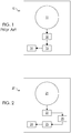
- FIG. 1 a typical prior art dryer system is schematically shown, wherein the dryer 10 includes a rotatable drum 11 , an air conduit 12 having a hand removable lint filter (not shown) secured therein, a blower motor 13 , and an air exhaust conduit 14 .
- the blower motor 13 pulls heated air through the rotatable drum 11 , through the air conduit 12 and lint filter, and then forces the air through the air exhaust conduit 14 to the outside of the dryer.
- the direction of air flow is indicated by the arrows.
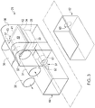
- FIGS. 2-13 The preferred embodiment of the present invention is shown in FIGS. 2-13 .
- the invention is schematically shown.
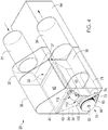
- FIGS. 3-13 detailed views of the lint filter cleaning and lint collection apparatus 25 and its operation are shown.
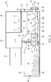
- the dryer 20 includes a rotatable drum 21 , an air conduit 22 , a blower motor 23 , an air exhaust conduit 24 , and an automatic lint filter cleaning and lint collection apparatus 25 , or "lint collection apparatus".
- the blower motor 23 pulls heated air through the rotatable drum 21 , through the air conduit 22 , through the lint collection apparatus 25 , and then forces the air through the air exhaust conduit 24 to the outside of the dryer.
- the direction of air flow is indicated by the arrows.
- air from the drum 21 preferably flows through an air inlet 31 into a first air chamber 32 , downwards through a first opening 33 into a lint collection chamber 34 , upwards through a lint filter 40 into a lint filter pivot chamber 36 , through a second opening 37 into a second air chamber 38 , and out of the apparatus 25 through an air outlet 39 .
- the lint filter 40 is secured within a pivotable lint filter housing 41 operable to pivot within the lint filter pivot chamber 36 .
- a flange 42 forms a perimeter along an inner surface of the apparatus 25 between the pivot chamber 36 and the collection chamber 34 , wherein the lint filter housing 41 abuts the flange 42 when the filter housing 41 is in a substantially horizontal or "home" position.
- the filter housing 41 includes a pivot arm 43 operably connected to a drive mechanism 70 and a spring arm 44 operably connected to a spring 46 .
- the spring first end 47 is preferably attached to the spring arm 44 and the spring second end 48 is preferably attached to the pivot chamber 36 housing such that the filter housing 41 is biased against the flange 42 .
- the spring 46 can be any type of spring suitable to bias the filter housing 41 against the flange 42 , although a compression spring is preferred.
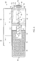
- the bottom of the lint collection chamber 34 forms a tapering hopper 35 to collect lint 50 .
- a rotatable auger 51 is mounted within the hopper 35 and extends through a short pipe 61 into a lint collection box 62 through a hole 63 therein.
- the lint collection box 62 is removably located within a collection box chamber 64 .
- a lint collection bag 66 is preferably removably securable within the collection box 62 .
- the collection bag 66 preferably comprises an air impermeable plastic.
- the collection bag 66 is secured within the collection box 62 such that the bag opening 67 aligns with the collection box hole 63 .
- the collection box 62 is insertable within the collection box chamber 64 such that the short pipe 61 extends through the collection box hole 63 and collection bag opening 67 into the collection bag 66 , thereby reversibly securing the collection bag 66 to the short pipe 61 .
- An airtight seal is formed between the collection bag 66 and the short pipe 61 .
- the inside surface of the short pipe 61 preferably includes a helical protrusion 68 (see FIG. 6 ) that enhances transfer of lint 50 from the hopper 35 through the pipe 61 and into the collection box 62 , described in greater detail below.
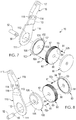
- the auger 51 comprises a shaft 52 having a helical flange 53 .
- the shaft 52 has a proximal end 55 that extends into the collection box 62 and a distal end 56 that is secured to the drive mechanism 70 .
- the outside diameter of the helical flange 53 decreases from the distal end 57 of the flight length towards the proximal end 58 of the flight length such that the helical flange 53 has a distal portion outside diameter 54a that is greater in the hopper 35 and a proximal portion outside diameter 54b that is reduced in the short pipe 61 (see FIGS. 5 and 6 ).
- the distance between the adjacent helical revolutions (pitch) decreases from the distal end 57 of the flight length towards the proximal end 58 of the flight length such that the pitch is greater in the hopper 35 and reduced in the short pipe 61 (see FIGS. 5 and 6 ).
- This auger design enhances transfer of lint 50 from the hopper 35 into the collection box 62 .
- the helical protrusion 68 along the inside surface of the short pipe 61 if present, cooperates with the above described auger design to further enhance transfer of lint 50 from the hopper 35 into the collection box 62 .
- the helix direction of the auger helical flange 53 is preferably opposite to the helix direction of the short pipe helical protrusion 68 .
- the auger helical flange 53 is a right-handed helix (as shown)
- the short pipe helical protrusion 68 is preferably a left-handed helix (as shown).
- the hopper 35 has a bottom end that forms an elongated channel that is slightly wider than the auger 51 and extends from the distal end 57 of the flight length to the short pipe 61 entrance.
- the bottom surface of the hopper 35 preferably has a distal segment 59a immediately subjacent the auger flight length distal end 57 and a recessed proximal segment 59b that slopes upward from the distal segment 59a to the short pipe 61 entrance, best seen in FIG. 6 .
- the recessed proximal segment 59b provides space for the lint to collect and the upward slope enhances the transfer of lint 50 from the hopper 35 into the short pipe 61 .
- the drive mechanism 70 comprises a drive motor 71 that drives a drive shaft 72 and drive wheel 73 , a drive belt 74 , and a drive pulley 80 .
- the drive pulley 80 is mounted for independent rotation about the auger shaft 52 .
- the drive pulley 80 has a spring 81 and a pin (detent) 82a , 82b secured within a recess 83 on each side so that each detent 82a, 82b is operable to extend outward from the drive pulley surface 84 .
- a proximal detent 82a is located on a proximal side 87 of the drive pulley 80 and a distal detent 82b is located on a distal side 86 of the drive pulley 80 .
- An auger drive wheel 90 is preferably mounted adjacent the distal side 86 of the drive pulley 80 , wherein the auger drive wheel 90 is secured to the auger shaft distal end 56 for concomitant rotation.
- the auger drive wheel 90 includes a sloping arcuate slot 91 that has a first end 92 that is coplanar with the surface 93 of the auger drive wheel 90 and a second end 94 that is recessed below the auger drive wheel surface 93 .
- a filter housing drive wheel 100 is preferably mounted adjacent the proximal side 87 of the drive pulley 80 , wherein the filter housing drive wheel 100 is mounted for independent rotation about the auger shaft 52 .
- the filter housing drive wheel 100 includes a sloping arcuate slot 101 that has a first end 102 that is coplanar with the surface 103 of the filter housing drive wheel 100 and a second end 104 that is recessed below the filter housing drive wheel surface 103 .
- the filter housing drive wheel 100 has an eccentric cam 105 formed along a proximal side 106 thereof.
- the drive mechanism 70 further comprises a crank arm 110 mounted adjacent the proximal side 106 of the filter housing drive wheel 100 .
- the crank arm 110 has a first end 111 having a hole 112 therein for receiving the eccentric cam 105 of the filter housing drive wheel 100 .
- the crank arm 110 has a second end 113 that is pivotably connected at a pivot point 114 to a first end 116 of a lift arm 115 .
- the lift arm 115 has a second end 117 that is pivotably connected to the pivot arm 43 of the filter housing 41 .
- a cam bar 120 extends from the apparatus 25 housing adjacent the lift arm 115 .
- the dryer 20 is operated through a drying cycle.
- the lint filter 40 and filter housing 41 are in the home position shown in FIG. 10 .
- the dryer 20 initiates a lint filter cleaning cycle and the drive mechanism 70 is actuated to clean the lint filter 40 .
- the drive motor 71 is actuated to rotate the drive wheel 73 in a first direction (e.g. clockwise) which causes the drive pulley 80 to rotate in a first direction (e.g. clockwise) by operation of the drive belt 74 .
- the spring-actuated proximal detent 82a will slide within the sloping arcuate slot 101 in the filter housing drive wheel 100 until it engages the recessed second end 104 of the arcuate slot 101 , after which, the proximal detent 82a will force the filter housing drive wheel 100 to rotate in the first direction concurrently therewith.
- the distal detent 82b slides within the sloping arcuate slot 91 of the auger drive wheel 90 but does not engage the auger drive wheel 90 because of the direction of rotation within the arcuate slot 91 .
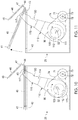
- the eccentric cam 105 urges the crank arm 110 angularly upwards which, in turn, urges the lift arm 115 angularly upwards, as shown in FIGS. 11 and 12 .
- the lift arm 115 moves upwards, it transmits lifting force to the pivot arm 43 which pivots the filter housing 41 upwards within the pivot chamber 36 .
- the maximum angle of the filter housing 41 relative to the flange 42 is between 30 to 90 degrees, most preferably 75 degrees.
- the lift arm 115 engages the cam bar 120 , which urges the first end 116 of the lift arm 115 and the second end 113 of the crank arm 110 to pivot about pivot point 114 relative to each other and away from cam bar 120 .
- the upward lifting force of the lift arm 115 is suddenly released and the filter housing 41 rapidly falls back into abutment with the flange 42 (see FIG. 13 ).
- This "slapping" action dislodges lint adhered to the filter 40 , allowing the lint to fall into the hopper 35 .
- the lint filter cleaning cycle can include one or more, preferably two, of these lint filter "slapping" cycles after each drying cycle.
- the dryer 20 initiates a lint collection cycle and the drive mechanism 70 is actuated to transfer lint from the hopper 35 to the collection box 62 .
- the drive motor 71 is actuated to rotate the drive wheel 73 in a second direction (e.g. counter-clockwise) which causes the drive pulley 80 to rotate in a second direction (e.g. counter-clockwise) by operation of the drive belt 74 .
- the spring-actuated distal detent 82b will slide within the sloping arcuate slot 91 in the auger drive wheel 90 until it engages the recessed second end 94 of the arcuate slot 91, after which, the distal detent 82b will force the auger drive wheel 90 to rotate in the second direction concurrently therewith.
- the proximal detent 82a slides within the sloping arcuate slot 101 of the filter housing drive wheel 100 but does not engage the filter housing drive wheel 100 because of the direction of rotation within the arcuate slot 101.
- the auger 51 rotates therewith and the helical flange 53 advances lint 50 from the hopper 35, through the short pipe 61, and into the collection bag 66 within the collection box 62.
- the lint collection cycle runs for a preset period of time, preferably 20 seconds. Once the lint collection cycle is completed, the dryer 20 will turn off.
- the auger 51 may include a reciprocating knife blade (not shown) mounted within the shaft 52 and extending slightly beyond the shaft surface to cut materials, such as hair, that wrap around the shaft 52. The knife blade can be actuated to cycle back and forth after the auger 51 has ceased rotating.
- the present invention cleans the lint filter 40 after each drying cycle and thus prevents lint buildup and interference with proper dryer function.
- the collection bag 66 should not need to be replaced for at least 6 months.
- a sensor detects when the collection bag 66 is full and activates a signal light on the dryer 20.
- the collection box 62 can be removed by a user through an access panel in the dryer 20, the collection bag 66 can be easily detached and removed from the collection box 62, a replacement collection bag 66 can be secured within the collection box 62, and the collection box 62 can be inserted back into the collection box chamber 64 to engage the short pipe 61.
- a safety feature can be included that prevents operation of the dryer 20 when the collection bag 66 is full.
Landscapes
- Engineering & Computer Science (AREA)
- Textile Engineering (AREA)
- Detail Structures Of Washing Machines And Dryers (AREA)
Claims (13)
- Flusenfilterreinigungs- und Flusensammelvorrichtung für einen Wäschetrockner, welche umfasst:a) eine Flusensammelkammer (34);b) einen Flusensammelbehälter (62);c) ein Rohr (61), das die Sammelkammer (34) und den Sammelbehälter (62) verbindet;d) eine Förderschnecke (51), die innerhalb der Sammelkammer drehbar gelagert ist, wobei die Förderschnecke (51) ein proximales Ende (58) und ein distales Ende (56) aufweist, wobei sich das proximale Ende (58) durch das Rohr (61) hindurch und in den Sammelbehälter (62) hinein erstreckt; unde) eine Antriebsbaugruppe (70), die mit dem distalen Ende (56) der Förderschnecke (51) betriebsfähig verbunden ist;f) wobei die Antriebsbaugruppe (70) dafür ausgelegt ist, die Förderschnecke (51) zu drehen, und die Förderschnecke (51) dafür ausgelegt ist, Flusen aus der Sammelkammer (34), durch das Rohr (61) hindurch und in den Sammelbehälter (62) zu bewegen, wenn sich die Förderschnecke (51) dreht,dadurch gekennzeichnet, dass die Flusenfilterreinigungs- und Flusensammelvorrichtung ferner umfasst:g) ein Vorrichtungsgehäuse;h) eine Flusenfilter-Schwenkkammer (36), die in einem oberen Abschnitt des Vorrichtungsgehäuses ausgebildet ist;i) wobei die Flusensammelkammer (34) in einem unteren Abschnitt des Vorrichtungsgehäuses unterhalb der Schwenkkammer (36) ausgebildet ist;j) ein Flusenfiltergehäuse (41), das innerhalb des Vorrichtungsgehäuses zwischen der Schwenkkammer (36) und der Sammelkammer (34) schwenkbar gelagert ist;k) ein Flusenfilter (40), das innerhalb des Filtergehäuses (41) befestigt ist;l) einen Flansch (42), der entlang einer Innenfläche des Vorrichtungsgehäuses zwischen der Flusenfilter-Schwenkkammer (36) und der Sammelkammer (34) ausgebildet ist, wobei das Filtergehäuse (41) in eine am Flansch (42) anliegende Position vorgespannt ist; undm) wobei die Antriebsbaugruppe (70) ferner dafür ausgelegt ist, das Filtergehäuse (41) innerhalb der Schwenkkammer (36) und von dem Flansch (42) weg zu schwenken, wobei die Antriebsbaugruppe (70) ferner dafür ausgelegt ist, das Filtergehäuse (41) freizugeben, nachdem das Filtergehäuse (41) von dem Flansch (42) weggeschwenkt worden ist, so dass das Filtergehäuse (41) zwangsweise in eine am Flansch (42) anliegende Position zurückkehrt, wobei das Flusenfilter dafür ausgelegt ist, an ihm anhaftende Flusen in die Sammelkammer (34) abzugeben, wenn das Filtergehäuse (41) zwangsweise in die am Flansch (42) anliegende Position zurückkehrt.
- Vorrichtung nach Anspruch 1, wobei die Sammelkammer (34) ein unteres Ende aufweist, welches einen lang gestreckten Kanal bildet, der sich vom distalen Ende (56) der Förderschnecke (51) bis zum Rohr (61) erstreckt, wobei die Förderschnecke (51) innerhalb des lang gestreckten Kanals drehbar gelagert ist.
- Vorrichtung nach Anspruch 2, wobei das untere Ende der Sammelkammer (34) eine Unterseite mit einem distalen Segment unmittelbar unterhalb des distalen Endes (56) der Förderschnecke (51) und einem rückspringenden proximalen Segment, welches von dem distalen Segment aus schräg nach oben zum Rohr (61) verläuft, aufweist.
- Vorrichtung nach Anspruch 1, wobei das Rohr (61) einen schraubenlinienförmigen Vorsprung (68) entlang einer Innenfläche desselben umfasst, um den Transport von Flusen durch das Rohr (61) hindurch und in den Flusensammelbehälter (62) zu fördern, wenn sich die Förderschnecke (51) dreht.
- Vorrichtung nach Anspruch 1, wobei die Förderschnecke (51) einen schraubenlinienförmigen Flansch (53) mit einem Außendurchmesser, welcher sich vom distalen Ende (56) der Förderschnecke (51) zum proximalen Ende (58) hin verringert, umfasst.
- Vorrichtung nach Anspruch 5, wobei der schraubenlinienförmige Flansch (53) eine Steigung aufweist, welche sich vom distalen Ende (56) der Förderschnecke (51) zum proximalen Ende (58) hin verringert.
- Vorrichtung nach Anspruch 1, wobei die Antriebsbaugruppe (70) umfasst:a) einen Antriebsmotor (71);b) ein Filtergehäuse-Antriebsrad, das mit dem Antriebsmotor (71) und dem Flusenfiltergehäuse betriebsfähig verbunden ist, wobei der Antriebsmotor (71) dafür ausgelegt ist, das Filtergehäuse-Antriebsrad in einer ersten Drehrichtung zu drehen, wobei das Filtergehäuse-Antriebsrad dafür ausgelegt ist, das Filtergehäuse innerhalb der Schwenkkammer (36) und von dem Flansch weg zu schwenken, wenn sich das Filtergehäuse-Antriebsrad in der ersten Drehrichtung dreht; undc) ein Förderschnecken-Antriebsrad, das mit dem Antriebsmotor (71) und dem distalen Ende (56) der Förderschnecke (51) betriebsfähig verbunden ist, wobei der Antriebsmotor (71) dafür ausgelegt ist, das Förderschnecken-Antriebsrad in einer zweiten Drehrichtung zu drehen, wobei das Förderschnecken-Antriebsrad dafür ausgelegt ist, die Förderschnecke (51) zu drehen, wenn sich das Förderschnecken-Antriebsrad in der zweiten Drehrichtung dreht, wobei die Förderschnecke (51) dafür ausgelegt ist, Flusen aus der Sammelkammer (34), durch das Rohr (61) hindurch und in den Sammelbehälter (62) zu bewegen, wenn sich die Förderschnecke (51) dreht.
- Vorrichtung nach Anspruch 1, wobei die Antriebsbaugruppe (70) umfasst:a) einen Antriebsmotor (71);b) eine Antriebsscheibe (80), die mit dem Antriebsmotor (71) betriebsfähig verbunden ist, wobei die Antriebsscheibe (80) eine erste Seite mit einer ersten federbetätigten Raste (82a) aufweist;c) einen Hubarm (115), der mit dem Flusenfiltergehäuse (41) betriebsfähig verbunden ist;d) einen Kurbelarm (110), der mit dem Hubarm (115) betriebsfähig verbunden ist; unde) ein Filtergehäuse-Antriebsrad (100), das mit der Antriebsscheibe (80) und dem Kurbelarm (110) betriebsfähig verbunden ist, wobei das Filtergehäuse-Antriebsrad (100) eine erste Seite mit einem darauf ausgebildeten Exzenternocken (105) zum Angreifen an dem Kurbelarm (110) und eine zweite Seite mit einem geneigten bogenförmigen Schlitz (91), welcher an einem vertieften Ende (104) endet, aufweist;f) wobei die Antriebsscheibe (80) dafür ausgelegt ist, sich in einer ersten Drehrichtung zu drehen, wobei die erste federbetätigte Raste (82a) dafür ausgelegt ist, in dem bogenförmigen Schlitz (91) des Filtergehäuse-Antriebsrades (100) zu gleiten und an dem vertieften Ende (104) des bogenförmigen Schlitzes des Filtergehäuse-Antriebsrades (100) anzugreifen und dadurch das Filtergehäuse-Antriebsrad (100) in der ersten Drehrichtung zu drehen, wenn sich die Antriebsscheibe (80) in der ersten Drehrichtung dreht, wobei das Filtergehäuse-Antriebsrad (100) dafür ausgelegt ist, den Kurbelarm (110) zu heben, wenn sich das Filtergehäuse-Antriebsrad (100) in der ersten Drehrichtung dreht, wobei der Kurbelarm (110) dafür ausgelegt ist, den Hubarm (115) zu heben, wenn der Kurbelarm (110) gehoben wird, wobei der Hubarm (115) dafür ausgelegt ist, das Filtergehäuse (41) innerhalb der Schwenkkammer (36) und von dem Flansch (42) weg zu schwenken, wenn der Hubarm (115) gehoben wird.
- Vorrichtung nach Anspruch 8, wobei die Antriebsbaugruppe (70) ferner eine Nockenstange (120) umfasst, die dem Hubarm (115) benachbart angebracht ist, wobei der Kurbelarm (110) ferner dafür ausgelegt ist, den Hubarm (115) in Eingriff mit der Nockenstange (120) zu schwenken, nachdem das Filtergehäuse (41) von dem Flansch (42) weggeschwenkt worden ist, wobei die Nockenstange (120) dafür ausgelegt ist, den Hubarm (115) relativ zu der Nockenstange (12) so zu schwenken, dass das Filtergehäuse (41) freigegeben wird, um in eine am Flansch (42) anliegende Position zurückzukehren.
- Vorrichtung nach Anspruch 8, wobei die Antriebsscheibe (80) eine zweite Seite mit einer zweiten federbetätigten Raste (82b) aufweist.
- Vorrichtung nach Anspruch 10, wobei die Antriebsbaugruppe (70) ferner ein Förderschnecken-Antriebsrad (90) umfasst, das mit der Antriebsscheibe (80) und dem distalen Ende (56) der Förderschnecke (51) betriebsfähig verbunden ist, wobei das Förderschnecken-Antriebsrad (90) eine erste Seite mit einem geneigten bogenförmigen Schlitz (101), welcher an einem vertieften Ende (104) endet, aufweist.
- Vorrichtung nach Anspruch 11, wobei die Antriebsscheibe (80) ferner dafür ausgelegt ist, sich in einer zweiten Drehrichtung zu drehen, wobei die zweite federbetätigte Raste dafür ausgelegt ist, in dem bogenförmigen Schlitz (101) des Förderschnecken-Antriebsrades (90) zu gleiten und an dem vertieften Ende (104) des bogenförmigen Schlitzes des Förderschnecken-Antriebsrades (90) anzugreifen und dadurch das Förderschnecken-Antriebsrad (90) in der zweiten Drehrichtung zu drehen, wenn sich die Antriebsscheibe (80) in der zweiten Drehrichtung dreht, wobei das Förderschnecken-Antriebsrad (90) dafür ausgelegt ist, die Förderschnecke (51) zu drehen, wenn sich das Förderschnecken-Antriebsrad (90) in der zweiten Drehrichtung dreht, wobei die Förderschnecke (51) dafür ausgelegt ist, Flusen aus der Sammelkammer (34), durch das Rohr (61) hindurch und in den Sammelbehälter (62) zu bewegen, wenn sich die Förderschnecke (51) dreht.
- Verfahren zum automatischen Reinigen eines Flusenfilters und Sammeln von Flusen in einem Wäschetrockner, welches die Schritte umfasst:1) Betreiben eines Wäschetrockners in einem Trockenzyklus;2) Reinigen eines Flusenfilters (40) am Ende des Trockenzyklus, wobei der Reinigungsschritt von einer Vorrichtung ausgeführt wird, welche umfasst:a) ein Vorrichtungsgehäuse;b) eine Flusenfilter-Schwenkkammer (36), die in einem oberen Abschnitt des Vorrichtungsgehäuses ausgebildet ist;c) eine Flusensammelkammer (34), die in einem unteren Abschnitt des Vorrichtungsgehäuses unterhalb der Schwenkkammer (36) ausgebildet ist;d) ein Flusenfiltergehäuse (41), das innerhalb des Vorrichtungsgehäuses zwischen der Schwenkkammer (36) und der Sammelkammer (34) schwenkbar gelagert ist;e) ein Flusenfilter (40), das innerhalb des Filtergehäuses befestigt ist;f) einen Flansch (42), der entlang einer Innenfläche des Vorrichtungsgehäuses zwischen der Schwenkkammer (36) und der Sammelkammer (34) ausgebildet ist, wobei das Filtergehäuse (41) in eine am Flansch (42) anliegende Position vorgespannt ist; undg) eine Antriebsbaugruppe (70), die mit dem Filtergehäuse (41) betriebsfähig verbunden ist;h) wobei die Antriebsbaugruppe (70) dafür ausgelegt ist, das Filtergehäuse (41) innerhalb der Schwenkkammer (36) und von dem Flansch (42) weg zu schwenken, wobei die Antriebsbaugruppe (70) ferner dafür ausgelegt ist, das Filtergehäuse (41) freizugeben, nachdem das Filtergehäuse (41) von dem Flansch (42) weggeschwenkt worden ist, so dass das Filtergehäuse (41) zwangsweise in eine am Flansch (42) anliegende Position zurückkehrt, wobei das Flusenfilter (40) dafür ausgelegt ist, an ihm anhaftende Flusen in die Sammelkammer (34) abzugeben, wenn das Filtergehäuse (41) zwangsweise in die am Flansch (42) anliegende Position zurückkehrt; und3) Sammeln von Flusen am Ende des Reinigungsschrittes, wobei dieser Sammelschritt von der Vorrichtung ausgeführt wird, wobei die Vorrichtung ferner umfasst:i) einen Flusensammelbehälter (62);j) ein Rohr (61), das die Sammelkammer (34) und den Sammelbehälter (62) verbindet;k) eine Förderschnecke (51), die innerhalb der Sammelkammer (34) drehbar gelagert ist, wobei die Förderschnecke (51) ein proximales Ende (58) und ein distales Ende (56) aufweist, wobei sich das proximale Ende (58) durch das Rohr (61) hindurch und in den Sammelbehälter (62) hinein erstreckt; undl) wobei die Antriebsbaugruppe (70) mit dem distalen Ende (56) der Förderschnecke (51) betriebsfähig verbunden ist;m) wobei die Antriebsbaugruppe (70) dafür ausgelegt ist, die Förderschnecke (51) zu drehen, und die Förderschnecke (51) dafür ausgelegt ist, Flusen aus der Sammelkammer (34), durch das Rohr (61) hindurch und in den Sammelbehälter (62) zu bewegen, wenn sich die Förderschnecke (51) dreht.
Applications Claiming Priority (2)
| Application Number | Priority Date | Filing Date | Title |
|---|---|---|---|
| US201361899918P | 2013-11-05 | 2013-11-05 | |
| PCT/US2014/063426 WO2015069561A2 (en) | 2013-11-05 | 2014-10-31 | Dryer lint collection system |
Publications (3)
| Publication Number | Publication Date |
|---|---|
| EP3066254A2 EP3066254A2 (de) | 2016-09-14 |
| EP3066254A4 EP3066254A4 (de) | 2017-06-21 |
| EP3066254B1 true EP3066254B1 (de) | 2018-12-26 |
Family
ID=53005883
Family Applications (1)
| Application Number | Title | Priority Date | Filing Date |
|---|---|---|---|
| EP14860690.8A Active EP3066254B1 (de) | 2013-11-05 | 2014-10-31 | Flusensammelsystem für einen trockner |
Country Status (3)
| Country | Link |
|---|---|
| US (1) | US9139950B2 (de) |
| EP (1) | EP3066254B1 (de) |
| WO (1) | WO2015069561A2 (de) |
Cited By (1)
| Publication number | Priority date | Publication date | Assignee | Title |
|---|---|---|---|---|
| US10590593B1 (en) * | 2018-10-02 | 2020-03-17 | Haier Us Appliance Solutions, Inc. | Lint cleaning assembly for a dryer appliance |
Families Citing this family (7)
| Publication number | Priority date | Publication date | Assignee | Title |
|---|---|---|---|---|
| JP2020081725A (ja) | 2018-11-30 | 2020-06-04 | 三星電子株式会社Samsung Electronics Co.,Ltd. | 衣類乾燥機 |
| US11230806B2 (en) | 2018-12-28 | 2022-01-25 | Whirlpool Corporation | Fabric treating appliance with pelletizer |
| US11519129B2 (en) | 2018-12-28 | 2022-12-06 | Whirlpool Corporation | Separation of lint from an exhaust airstream within a laundry appliance |
| US12366029B2 (en) | 2021-11-18 | 2025-07-22 | Haier Us Appliance Solutions, Inc. | Dryer appliance and filter apparatus |
| CN119343493A (zh) * | 2022-06-09 | 2025-01-21 | 伊莱克斯家用电器股份公司 | 具有设置有清洁装置的微粒过滤器装置的衣物洗涤机以及用于移除清洁装置的方法 |
| EP4536886A1 (de) * | 2022-06-09 | 2025-04-16 | Electrolux Appliances Aktiebolag | Mikropartikelfiltervorrichtung für eine waschmaschine mit einer reinigungsvorrichtung und verfahren zum entfernen der reinigungsvorrichtung |
| CN120008323B (zh) * | 2025-04-18 | 2025-06-13 | 湖北天源纺织股份有限公司 | 一种纺织品生产用风干装置 |
Family Cites Families (12)
| Publication number | Priority date | Publication date | Assignee | Title |
|---|---|---|---|---|
| US1355293A (en) * | 1920-01-17 | 1920-10-12 | Frank M Watkins | Drying-tumbler |
| US2886900A (en) | 1955-04-15 | 1959-05-19 | Murray Corp | Drier lint collector |
| US3748746A (en) * | 1972-05-01 | 1973-07-31 | Whirlpool Co | Lint screen for dryer |
| US4162148A (en) * | 1975-09-23 | 1979-07-24 | Ltg Lufttechnische Gmbh | Filtering apparatus |
| US4314409A (en) * | 1980-02-06 | 1982-02-09 | Whirlpool Corporation | Automatic lint screen cleaner and storage system for dryer |
| US4462170A (en) * | 1982-05-21 | 1984-07-31 | Whirlpool Corporation | Sump for lint screen cleaner and storage system for a dryer |
| US4700492A (en) | 1986-02-05 | 1987-10-20 | Whirlpool Corporation | Air actuated automatic lint screen cleaning system for dryer |
| JPS62279820A (ja) * | 1986-05-28 | 1987-12-04 | Ryobi Ltd | 集塵機 |
| US6101741A (en) * | 1998-04-15 | 2000-08-15 | Maytag Corporation | Gravity assisted lint trap |
| JP4706571B2 (ja) * | 2006-06-29 | 2011-06-22 | パナソニック株式会社 | 洗濯乾燥機 |
| EP2146000A1 (de) * | 2008-07-14 | 2010-01-20 | Electrolux Home Products Corporation N.V. | Waschmaschine mit Flusenentfernungsvorrichtung |
| JP2013135789A (ja) * | 2011-12-28 | 2013-07-11 | Panasonic Corp | 衣類乾燥機 |
-
2014
- 2014-10-31 EP EP14860690.8A patent/EP3066254B1/de active Active
- 2014-10-31 WO PCT/US2014/063426 patent/WO2015069561A2/en not_active Ceased
- 2014-10-31 US US14/529,698 patent/US9139950B2/en active Active
Non-Patent Citations (1)
| Title |
|---|
| None * |
Cited By (1)
| Publication number | Priority date | Publication date | Assignee | Title |
|---|---|---|---|---|
| US10590593B1 (en) * | 2018-10-02 | 2020-03-17 | Haier Us Appliance Solutions, Inc. | Lint cleaning assembly for a dryer appliance |
Also Published As
| Publication number | Publication date |
|---|---|
| US20150121719A1 (en) | 2015-05-07 |
| WO2015069561A3 (en) | 2015-11-05 |
| WO2015069561A2 (en) | 2015-05-14 |
| EP3066254A2 (de) | 2016-09-14 |
| US9139950B2 (en) | 2015-09-22 |
| EP3066254A4 (de) | 2017-06-21 |
Similar Documents
| Publication | Publication Date | Title |
|---|---|---|
| EP3066254B1 (de) | Flusensammelsystem für einen trockner | |
| US7798101B2 (en) | Apparatus and method to remove animal waste from litter | |
| JP5179555B2 (ja) | 表面処理電気器具 | |
| US4314409A (en) | Automatic lint screen cleaner and storage system for dryer | |
| CN208524758U (zh) | 真空吸尘器 | |
| JP5179554B2 (ja) | 表面処理電気器具 | |
| US7954739B2 (en) | Garbage disposal apparatus | |
| JP3953386B2 (ja) | 真空掃除機用サイクロン集塵装置 | |
| JP5070322B2 (ja) | 電気掃除機 | |
| JP5042350B2 (ja) | 表面処理電気器具 | |
| EP2458070A1 (de) | Kleidertrockner und Flusenreinigungsvorrichtung dafür | |
| KR101490979B1 (ko) | 다기능 헤어드라이기 | |
| JP2011083614A (ja) | 表面処理電気器具 | |
| US7654070B2 (en) | Mown-gross collecting bucket | |
| TW201249379A (en) | Juicer | |
| EP2043495A1 (de) | Teppichreinigungsvorrichtung und teppichreinigungsverfahren | |
| FR3000504A1 (fr) | Appareil de traitement de linge | |
| CN107223032A (zh) | 蔬菜甩水器 | |
| CN101617929A (zh) | 旋风分离装置 | |
| FR2931489A1 (fr) | Procede de retrait des peluches dans une machine a secher le linge comprenant un filtre a peluches | |
| KR20170041504A (ko) | 견과류 로스팅 장치, 및 이를 이용한 견과류 로스팅 방법 | |
| CA2773717C (en) | Vacuum device with positive pressure tank | |
| FR2931487A1 (fr) | Machine a secher le linge comprenant un filtre a peluches | |
| US9192100B1 (en) | Apparatus for clearing matted grass clippings from lawnmower discharge port | |
| US20250018320A1 (en) | Portable fluid filtering apparatus |
Legal Events
| Date | Code | Title | Description |
|---|---|---|---|
| PUAI | Public reference made under article 153(3) epc to a published international application that has entered the european phase |
Free format text: ORIGINAL CODE: 0009012 |
|
| 17P | Request for examination filed |
Effective date: 20160513 |
|
| AK | Designated contracting states |
Kind code of ref document: A2 Designated state(s): AL AT BE BG CH CY CZ DE DK EE ES FI FR GB GR HR HU IE IS IT LI LT LU LV MC MK MT NL NO PL PT RO RS SE SI SK SM TR |
|
| AX | Request for extension of the european patent |
Extension state: BA ME |
|
| DAX | Request for extension of the european patent (deleted) | ||
| A4 | Supplementary search report drawn up and despatched |
Effective date: 20170522 |
|
| RIC1 | Information provided on ipc code assigned before grant |
Ipc: D06F 58/22 20060101AFI20170516BHEP |
|
| GRAP | Despatch of communication of intention to grant a patent |
Free format text: ORIGINAL CODE: EPIDOSNIGR1 |
|
| STAA | Information on the status of an ep patent application or granted ep patent |
Free format text: STATUS: GRANT OF PATENT IS INTENDED |
|
| INTG | Intention to grant announced |
Effective date: 20180711 |
|
| GRAS | Grant fee paid |
Free format text: ORIGINAL CODE: EPIDOSNIGR3 |
|
| GRAA | (expected) grant |
Free format text: ORIGINAL CODE: 0009210 |
|
| STAA | Information on the status of an ep patent application or granted ep patent |
Free format text: STATUS: THE PATENT HAS BEEN GRANTED |
|
| AK | Designated contracting states |
Kind code of ref document: B1 Designated state(s): AL AT BE BG CH CY CZ DE DK EE ES FI FR GB GR HR HU IE IS IT LI LT LU LV MC MK MT NL NO PL PT RO RS SE SI SK SM TR |
|
| REG | Reference to a national code |
Ref country code: GB Ref legal event code: FG4D |
|
| REG | Reference to a national code |
Ref country code: CH Ref legal event code: EP |
|
| REG | Reference to a national code |
Ref country code: AT Ref legal event code: REF Ref document number: 1081571 Country of ref document: AT Kind code of ref document: T Effective date: 20190115 |
|
| REG | Reference to a national code |
Ref country code: DE Ref legal event code: R096 Ref document number: 602014038872 Country of ref document: DE |
|
| REG | Reference to a national code |
Ref country code: IE Ref legal event code: FG4D |
|
| PG25 | Lapsed in a contracting state [announced via postgrant information from national office to epo] |
Ref country code: LV Free format text: LAPSE BECAUSE OF FAILURE TO SUBMIT A TRANSLATION OF THE DESCRIPTION OR TO PAY THE FEE WITHIN THE PRESCRIBED TIME-LIMIT Effective date: 20181226 Ref country code: HR Free format text: LAPSE BECAUSE OF FAILURE TO SUBMIT A TRANSLATION OF THE DESCRIPTION OR TO PAY THE FEE WITHIN THE PRESCRIBED TIME-LIMIT Effective date: 20181226 Ref country code: LT Free format text: LAPSE BECAUSE OF FAILURE TO SUBMIT A TRANSLATION OF THE DESCRIPTION OR TO PAY THE FEE WITHIN THE PRESCRIBED TIME-LIMIT Effective date: 20181226 Ref country code: BG Free format text: LAPSE BECAUSE OF FAILURE TO SUBMIT A TRANSLATION OF THE DESCRIPTION OR TO PAY THE FEE WITHIN THE PRESCRIBED TIME-LIMIT Effective date: 20190326 Ref country code: NO Free format text: LAPSE BECAUSE OF FAILURE TO SUBMIT A TRANSLATION OF THE DESCRIPTION OR TO PAY THE FEE WITHIN THE PRESCRIBED TIME-LIMIT Effective date: 20190326 Ref country code: FI Free format text: LAPSE BECAUSE OF FAILURE TO SUBMIT A TRANSLATION OF THE DESCRIPTION OR TO PAY THE FEE WITHIN THE PRESCRIBED TIME-LIMIT Effective date: 20181226 |
|
| REG | Reference to a national code |
Ref country code: NL Ref legal event code: MP Effective date: 20181226 |
|
| REG | Reference to a national code |
Ref country code: LT Ref legal event code: MG4D |
|
| PG25 | Lapsed in a contracting state [announced via postgrant information from national office to epo] |
Ref country code: GR Free format text: LAPSE BECAUSE OF FAILURE TO SUBMIT A TRANSLATION OF THE DESCRIPTION OR TO PAY THE FEE WITHIN THE PRESCRIBED TIME-LIMIT Effective date: 20190327 Ref country code: RS Free format text: LAPSE BECAUSE OF FAILURE TO SUBMIT A TRANSLATION OF THE DESCRIPTION OR TO PAY THE FEE WITHIN THE PRESCRIBED TIME-LIMIT Effective date: 20181226 Ref country code: SE Free format text: LAPSE BECAUSE OF FAILURE TO SUBMIT A TRANSLATION OF THE DESCRIPTION OR TO PAY THE FEE WITHIN THE PRESCRIBED TIME-LIMIT Effective date: 20181226 Ref country code: AL Free format text: LAPSE BECAUSE OF FAILURE TO SUBMIT A TRANSLATION OF THE DESCRIPTION OR TO PAY THE FEE WITHIN THE PRESCRIBED TIME-LIMIT Effective date: 20181226 |
|
| REG | Reference to a national code |
Ref country code: AT Ref legal event code: MK05 Ref document number: 1081571 Country of ref document: AT Kind code of ref document: T Effective date: 20181226 |
|
| PG25 | Lapsed in a contracting state [announced via postgrant information from national office to epo] |
Ref country code: NL Free format text: LAPSE BECAUSE OF FAILURE TO SUBMIT A TRANSLATION OF THE DESCRIPTION OR TO PAY THE FEE WITHIN THE PRESCRIBED TIME-LIMIT Effective date: 20181226 |
|
| PG25 | Lapsed in a contracting state [announced via postgrant information from national office to epo] |
Ref country code: PL Free format text: LAPSE BECAUSE OF FAILURE TO SUBMIT A TRANSLATION OF THE DESCRIPTION OR TO PAY THE FEE WITHIN THE PRESCRIBED TIME-LIMIT Effective date: 20181226 Ref country code: IT Free format text: LAPSE BECAUSE OF FAILURE TO SUBMIT A TRANSLATION OF THE DESCRIPTION OR TO PAY THE FEE WITHIN THE PRESCRIBED TIME-LIMIT Effective date: 20181226 Ref country code: PT Free format text: LAPSE BECAUSE OF FAILURE TO SUBMIT A TRANSLATION OF THE DESCRIPTION OR TO PAY THE FEE WITHIN THE PRESCRIBED TIME-LIMIT Effective date: 20190426 Ref country code: ES Free format text: LAPSE BECAUSE OF FAILURE TO SUBMIT A TRANSLATION OF THE DESCRIPTION OR TO PAY THE FEE WITHIN THE PRESCRIBED TIME-LIMIT Effective date: 20181226 Ref country code: CZ Free format text: LAPSE BECAUSE OF FAILURE TO SUBMIT A TRANSLATION OF THE DESCRIPTION OR TO PAY THE FEE WITHIN THE PRESCRIBED TIME-LIMIT Effective date: 20181226 |
|
| PG25 | Lapsed in a contracting state [announced via postgrant information from national office to epo] |
Ref country code: RO Free format text: LAPSE BECAUSE OF FAILURE TO SUBMIT A TRANSLATION OF THE DESCRIPTION OR TO PAY THE FEE WITHIN THE PRESCRIBED TIME-LIMIT Effective date: 20181226 Ref country code: SK Free format text: LAPSE BECAUSE OF FAILURE TO SUBMIT A TRANSLATION OF THE DESCRIPTION OR TO PAY THE FEE WITHIN THE PRESCRIBED TIME-LIMIT Effective date: 20181226 Ref country code: IS Free format text: LAPSE BECAUSE OF FAILURE TO SUBMIT A TRANSLATION OF THE DESCRIPTION OR TO PAY THE FEE WITHIN THE PRESCRIBED TIME-LIMIT Effective date: 20190426 Ref country code: EE Free format text: LAPSE BECAUSE OF FAILURE TO SUBMIT A TRANSLATION OF THE DESCRIPTION OR TO PAY THE FEE WITHIN THE PRESCRIBED TIME-LIMIT Effective date: 20181226 Ref country code: SM Free format text: LAPSE BECAUSE OF FAILURE TO SUBMIT A TRANSLATION OF THE DESCRIPTION OR TO PAY THE FEE WITHIN THE PRESCRIBED TIME-LIMIT Effective date: 20181226 |
|
| REG | Reference to a national code |
Ref country code: DE Ref legal event code: R097 Ref document number: 602014038872 Country of ref document: DE |
|
| PG25 | Lapsed in a contracting state [announced via postgrant information from national office to epo] |
Ref country code: AT Free format text: LAPSE BECAUSE OF FAILURE TO SUBMIT A TRANSLATION OF THE DESCRIPTION OR TO PAY THE FEE WITHIN THE PRESCRIBED TIME-LIMIT Effective date: 20181226 Ref country code: DK Free format text: LAPSE BECAUSE OF FAILURE TO SUBMIT A TRANSLATION OF THE DESCRIPTION OR TO PAY THE FEE WITHIN THE PRESCRIBED TIME-LIMIT Effective date: 20181226 |
|
| PLBE | No opposition filed within time limit |
Free format text: ORIGINAL CODE: 0009261 |
|
| STAA | Information on the status of an ep patent application or granted ep patent |
Free format text: STATUS: NO OPPOSITION FILED WITHIN TIME LIMIT |
|
| 26N | No opposition filed |
Effective date: 20190927 |
|
| PG25 | Lapsed in a contracting state [announced via postgrant information from national office to epo] |
Ref country code: SI Free format text: LAPSE BECAUSE OF FAILURE TO SUBMIT A TRANSLATION OF THE DESCRIPTION OR TO PAY THE FEE WITHIN THE PRESCRIBED TIME-LIMIT Effective date: 20181226 |
|
| PG25 | Lapsed in a contracting state [announced via postgrant information from national office to epo] |
Ref country code: TR Free format text: LAPSE BECAUSE OF FAILURE TO SUBMIT A TRANSLATION OF THE DESCRIPTION OR TO PAY THE FEE WITHIN THE PRESCRIBED TIME-LIMIT Effective date: 20181226 |
|
| PG25 | Lapsed in a contracting state [announced via postgrant information from national office to epo] |
Ref country code: MC Free format text: LAPSE BECAUSE OF FAILURE TO SUBMIT A TRANSLATION OF THE DESCRIPTION OR TO PAY THE FEE WITHIN THE PRESCRIBED TIME-LIMIT Effective date: 20181226 |
|
| REG | Reference to a national code |
Ref country code: CH Ref legal event code: PL |
|
| PG25 | Lapsed in a contracting state [announced via postgrant information from national office to epo] |
Ref country code: LU Free format text: LAPSE BECAUSE OF NON-PAYMENT OF DUE FEES Effective date: 20191031 Ref country code: LI Free format text: LAPSE BECAUSE OF NON-PAYMENT OF DUE FEES Effective date: 20191031 Ref country code: CH Free format text: LAPSE BECAUSE OF NON-PAYMENT OF DUE FEES Effective date: 20191031 |
|
| REG | Reference to a national code |
Ref country code: BE Ref legal event code: MM Effective date: 20191031 |
|
| PG25 | Lapsed in a contracting state [announced via postgrant information from national office to epo] |
Ref country code: BE Free format text: LAPSE BECAUSE OF NON-PAYMENT OF DUE FEES Effective date: 20191031 |
|
| PG25 | Lapsed in a contracting state [announced via postgrant information from national office to epo] |
Ref country code: IE Free format text: LAPSE BECAUSE OF NON-PAYMENT OF DUE FEES Effective date: 20191031 |
|
| PG25 | Lapsed in a contracting state [announced via postgrant information from national office to epo] |
Ref country code: CY Free format text: LAPSE BECAUSE OF FAILURE TO SUBMIT A TRANSLATION OF THE DESCRIPTION OR TO PAY THE FEE WITHIN THE PRESCRIBED TIME-LIMIT Effective date: 20181226 |
|
| PG25 | Lapsed in a contracting state [announced via postgrant information from national office to epo] |
Ref country code: HU Free format text: LAPSE BECAUSE OF FAILURE TO SUBMIT A TRANSLATION OF THE DESCRIPTION OR TO PAY THE FEE WITHIN THE PRESCRIBED TIME-LIMIT; INVALID AB INITIO Effective date: 20141031 Ref country code: MT Free format text: LAPSE BECAUSE OF FAILURE TO SUBMIT A TRANSLATION OF THE DESCRIPTION OR TO PAY THE FEE WITHIN THE PRESCRIBED TIME-LIMIT Effective date: 20181226 |
|
| PG25 | Lapsed in a contracting state [announced via postgrant information from national office to epo] |
Ref country code: MK Free format text: LAPSE BECAUSE OF FAILURE TO SUBMIT A TRANSLATION OF THE DESCRIPTION OR TO PAY THE FEE WITHIN THE PRESCRIBED TIME-LIMIT Effective date: 20181226 |
|
| PGFP | Annual fee paid to national office [announced via postgrant information from national office to epo] |
Ref country code: DE Payment date: 20241010 Year of fee payment: 11 |
|
| PGFP | Annual fee paid to national office [announced via postgrant information from national office to epo] |
Ref country code: FR Payment date: 20241010 Year of fee payment: 11 |
|
| PGFP | Annual fee paid to national office [announced via postgrant information from national office to epo] |
Ref country code: GB Payment date: 20250915 Year of fee payment: 12 |