EP3064698A1 - Gate - Google Patents
Gate Download PDFInfo
- Publication number
- EP3064698A1 EP3064698A1 EP16157153.4A EP16157153A EP3064698A1 EP 3064698 A1 EP3064698 A1 EP 3064698A1 EP 16157153 A EP16157153 A EP 16157153A EP 3064698 A1 EP3064698 A1 EP 3064698A1
- Authority
- EP
- European Patent Office
- Prior art keywords
- door
- seal carrier
- door leaf
- seal
- door frame
- Prior art date
- Legal status (The legal status is an assumption and is not a legal conclusion. Google has not performed a legal analysis and makes no representation as to the accuracy of the status listed.)
- Granted
Links
- 238000007789 sealing Methods 0.000 claims abstract description 28
- 238000010276 construction Methods 0.000 description 2
- 238000013459 approach Methods 0.000 description 1
- 230000000052 comparative effect Effects 0.000 description 1
- 230000000694 effects Effects 0.000 description 1
- 230000036316 preload Effects 0.000 description 1
- 239000000565 sealant Substances 0.000 description 1
Images


Classifications
-
- E—FIXED CONSTRUCTIONS
- E06—DOORS, WINDOWS, SHUTTERS, OR ROLLER BLINDS IN GENERAL; LADDERS
- E06B—FIXED OR MOVABLE CLOSURES FOR OPENINGS IN BUILDINGS, VEHICLES, FENCES OR LIKE ENCLOSURES IN GENERAL, e.g. DOORS, WINDOWS, BLINDS, GATES
- E06B7/00—Special arrangements or measures in connection with doors or windows
- E06B7/16—Sealing arrangements on wings or parts co-operating with the wings
- E06B7/18—Sealing arrangements on wings or parts co-operating with the wings by means of movable edgings, e.g. draught sealings additionally used for bolting, e.g. by spring force or with operating lever
- E06B7/20—Sealing arrangements on wings or parts co-operating with the wings by means of movable edgings, e.g. draught sealings additionally used for bolting, e.g. by spring force or with operating lever automatically withdrawn when the wing is opened, e.g. by means of magnetic attraction, a pin or an inclined surface, especially for sills
-
- E—FIXED CONSTRUCTIONS
- E05—LOCKS; KEYS; WINDOW OR DOOR FITTINGS; SAFES
- E05D—HINGES OR SUSPENSION DEVICES FOR DOORS, WINDOWS OR WINGS
- E05D15/00—Suspension arrangements for wings
- E05D15/16—Suspension arrangements for wings for wings sliding vertically more or less in their own plane
- E05D15/165—Details, e.g. sliding or rolling guides
-
- E—FIXED CONSTRUCTIONS
- E05—LOCKS; KEYS; WINDOW OR DOOR FITTINGS; SAFES
- E05D—HINGES OR SUSPENSION DEVICES FOR DOORS, WINDOWS OR WINGS
- E05D15/00—Suspension arrangements for wings
- E05D15/16—Suspension arrangements for wings for wings sliding vertically more or less in their own plane
- E05D15/22—Suspension arrangements for wings for wings sliding vertically more or less in their own plane allowing an additional movement
-
- E—FIXED CONSTRUCTIONS
- E06—DOORS, WINDOWS, SHUTTERS, OR ROLLER BLINDS IN GENERAL; LADDERS
- E06B—FIXED OR MOVABLE CLOSURES FOR OPENINGS IN BUILDINGS, VEHICLES, FENCES OR LIKE ENCLOSURES IN GENERAL, e.g. DOORS, WINDOWS, BLINDS, GATES
- E06B3/00—Window sashes, door leaves, or like elements for closing wall or like openings; Layout of fixed or moving closures, e.g. windows in wall or like openings; Features of rigidly-mounted outer frames relating to the mounting of wing frames
- E06B3/32—Arrangements of wings characterised by the manner of movement; Arrangements of movable wings in openings; Features of wings or frames relating solely to the manner of movement of the wing
- E06B3/48—Wings connected at their edges, e.g. foldable wings
- E06B3/485—Sectional doors
-
- E—FIXED CONSTRUCTIONS
- E06—DOORS, WINDOWS, SHUTTERS, OR ROLLER BLINDS IN GENERAL; LADDERS
- E06B—FIXED OR MOVABLE CLOSURES FOR OPENINGS IN BUILDINGS, VEHICLES, FENCES OR LIKE ENCLOSURES IN GENERAL, e.g. DOORS, WINDOWS, BLINDS, GATES
- E06B7/00—Special arrangements or measures in connection with doors or windows
- E06B7/16—Sealing arrangements on wings or parts co-operating with the wings
- E06B7/18—Sealing arrangements on wings or parts co-operating with the wings by means of movable edgings, e.g. draught sealings additionally used for bolting, e.g. by spring force or with operating lever
-
- E—FIXED CONSTRUCTIONS
- E05—LOCKS; KEYS; WINDOW OR DOOR FITTINGS; SAFES
- E05D—HINGES OR SUSPENSION DEVICES FOR DOORS, WINDOWS OR WINGS
- E05D15/00—Suspension arrangements for wings
- E05D15/16—Suspension arrangements for wings for wings sliding vertically more or less in their own plane
- E05D15/22—Suspension arrangements for wings for wings sliding vertically more or less in their own plane allowing an additional movement
- E05D2015/225—Suspension arrangements for wings for wings sliding vertically more or less in their own plane allowing an additional movement specially adapted for overhead wings
-
- E—FIXED CONSTRUCTIONS
- E05—LOCKS; KEYS; WINDOW OR DOOR FITTINGS; SAFES
- E05Y—INDEXING SCHEME ASSOCIATED WITH SUBCLASSES E05D AND E05F, RELATING TO CONSTRUCTION ELEMENTS, ELECTRIC CONTROL, POWER SUPPLY, POWER SIGNAL OR TRANSMISSION, USER INTERFACES, MOUNTING OR COUPLING, DETAILS, ACCESSORIES, AUXILIARY OPERATIONS NOT OTHERWISE PROVIDED FOR, APPLICATION THEREOF
- E05Y2800/00—Details, accessories and auxiliary operations not otherwise provided for
- E05Y2800/10—Additional functions
- E05Y2800/12—Sealing
-
- E—FIXED CONSTRUCTIONS
- E05—LOCKS; KEYS; WINDOW OR DOOR FITTINGS; SAFES
- E05Y—INDEXING SCHEME ASSOCIATED WITH SUBCLASSES E05D AND E05F, RELATING TO CONSTRUCTION ELEMENTS, ELECTRIC CONTROL, POWER SUPPLY, POWER SIGNAL OR TRANSMISSION, USER INTERFACES, MOUNTING OR COUPLING, DETAILS, ACCESSORIES, AUXILIARY OPERATIONS NOT OTHERWISE PROVIDED FOR, APPLICATION THEREOF
- E05Y2900/00—Application of doors, windows, wings or fittings thereof
- E05Y2900/10—Application of doors, windows, wings or fittings thereof for buildings or parts thereof
- E05Y2900/106—Application of doors, windows, wings or fittings thereof for buildings or parts thereof for garages
-
- E—FIXED CONSTRUCTIONS
- E06—DOORS, WINDOWS, SHUTTERS, OR ROLLER BLINDS IN GENERAL; LADDERS
- E06B—FIXED OR MOVABLE CLOSURES FOR OPENINGS IN BUILDINGS, VEHICLES, FENCES OR LIKE ENCLOSURES IN GENERAL, e.g. DOORS, WINDOWS, BLINDS, GATES
- E06B1/00—Border constructions of openings in walls, floors, or ceilings; Frames to be rigidly mounted in such openings
- E06B1/04—Frames for doors, windows, or the like to be fixed in openings
- E06B1/52—Frames specially adapted for doors
- E06B1/522—Frames specially adapted for doors for overhead garage doors
Definitions
- the invention relates to a gate with a door frame, a door leaf of a plurality hingedly connected door leaf segments, attached to the door frame rails in which the Torblattsegmente are guided laterally, and arranged on the door frame seal for sealing a gap between the door frame and the door leaf when the gate is closed.
- the door leaf is movable between an open position and a closed position.
- the seal comprises at least one weather strip that bears against the door leaf when the door leaf is in the closed position.
- the gate is in particular a sectional door or a roller door.
- a gate with the aforementioned features is beispielswese from DE 10 2004 010 367 U1 known.
- the door frame has vertical frame profiles which engage over the edge section of the door leaf when the door leaf is in the closed position.
- a sealing strip made of an elastomeric plastic is attached in each case, which bears against the outer surface of the door leaf.
- the door leaf segments slide along the sealing strip.
- the sealing strips are exposed to wear.
- the voltage applied to the door leaf sealing strip form a resistance that must be overcome by a door drive when opening and closing the gate.
- an exact distance must be set between the door leaf segments and the sealing strip. If the distance is chosen to be too large in order to avoid the aforementioned disadvantages, this leads to losses with regard to the sealing effect.
- the door leaf segments are guided on vertical rails, which are mounted on swing levers movable on the door frame.
- the door leaf reaches a stop at the foot end of the rails, so that the weight of the door leaf is transferred to the rails and the rails movably mounted on the rocker arms execute a sideways movement towards the door frame as a result of the gravitational force acting on them. Due to the sideways movement, the door leaf is pressed against the weather strip attached to the door frame.
- the invention has the object, a goal, which has the features described above, in such a way that the door leaf when opening and closing the door without frictional resistance can be moved along the arranged on the door frame seal and is sealed in the door closed position effectively on the door frame.
- the mass of the movably mounted parts should be low.
- the construction should also have no disadvantage in terms of burglary protection.
- a seal for sealing a gap between the door frame and the door leaf is arranged, which comprises at least one sealing strip, which bears against the door leaf when the door leaf is in the closed position.
- the sealing strip is attached to a seal carrier, which is movably mounted on the door frame and is adjustable transversely to the door opening between a first position and a second position. Further, a retaining means is provided which holds the seal carrier in the first position when the door leaf is not in the closed position.
- an adjusting device which moves the seal carrier from the first position to the second position as soon as the door leaf reaches the closed position during a closing movement, and which moves the seal carrier of the door leaf back into the first position as soon as the door leaf with an opening movement leaves the closed position again.
- the first position is suitably chosen so that the sealing strip does not touch the surface of the door leaf segments when the seal carrier is in this position.
- the seal carrier occupies the second position the sealing strip is applied to the door leaf surface with sufficient preload for the seal.
- the mass of the seal carrier to be moved is small compared to the mass of the door leaf, so that the storage of the Sealant is not exposed to great forces and can be structurally simple.
- the Torblattsegmente are guided laterally in guide rails which are fixed to the door frame.
- the frame elements of the door frame and attached rails form dimensionally stable units that can meet high requirements for anti-burglary protection.
- the movably mounted seal carrier neither limits the stability of the door frame nor is the movably mounted seal carrier relevant to the guidance of the door leaf segments.
- the seal carrier is preferably articulated to levers of a hinge assembly, wherein the seal carrier and the hinge assembly form a Gelenkparallelogramm.
- the adjusting device for adjusting the seal carrier may comprise electromechanically, pneumatically or hydraulically operable actuators which contain switching signals from sensors which interrogate the position of the door leaf.
- the adjusting device operates without external energy and has a shift lever which is kinematically connected to the seal carrier and is arranged in the path of the door leaf.
- a shift lever which is kinematically connected to the seal carrier and is arranged in the path of the door leaf.
- an arrangement such that the shift lever is switchable by the impeller axis of a lowermost Torblattsegment along the rail leading roller.
- the shift lever is suitably designed as an angle lever which is pivotally mounted on a bearing bracket attached to the door frame and is kinematically connected by a sliding joint with the seal carrier associated with the hinge assembly.
- a return spring is preferably provided, which acts on the seal carrier or kinematically connected to the seal carrier shift lever. Once the seal carrier reaches the first position or approaches the first position, the retainer becomes effective. This preferably has at least one magnet.
- the seal carrier and the parts associated with the seal carrier can be integrated in the door frame.
- An advantageous embodiment of the invention provides that at least parts of the door frame are made of a hollow profile and that the seal carrier, the retaining device and the adjusting device are arranged within the hollow profile.
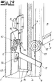
- the Fig. 1 shows a horizontal sectional detail of a sectional door with a door frame 1, a door leaf 2 of a plurality of hingedly connected door leaf segments 3, a fixed to the door frame 1 rail 4, in which the Torblattsegmente 3 are guided laterally, and arranged on the door frame 1 seal 5 for sealing a gap between the door frame 1 and the door leaf 2 with the door closed.
- the door leaf 2 is movable between a closed position, in which a door opening is completely closed, and an opening position releasing the door opening.
- the seal 5 comprises at least one sealing strip 6, which bears against the door leaf 2 when the door leaf 2 is in the closed position.
- the sealing strip 6 is fixed to a seal carrier 7 which is movably mounted on the door frame 1 and is adjustable transversely to the door opening between a first position and a second position.
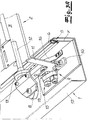
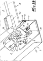
- the first position is in the Fig. 2a and 3a shown.
- the seal carrier 7 in the in the Fig. 2a and 3a is shown, the sealing strip 6 does not touch the surface of the Torblattsegmente 3 and a gap s between the sealing strip 6 and the outer surface of the Torblattsegmente 3 is present.
- a retaining device 8 holds the seal carrier 7 in the in the Fig. 2a and 3a shown first position, as long as the door leaf 2 is not in the closed position.
- the retaining device 8 preferably has at least one magnet.
- an adjusting device 9 is provided for adjusting the seal carrier 7. This moves the seal carrier from the first position into one in the Fig. 2b and 3b shown second position as soon as the door leaf 2 reaches the closed position during a closing movement. Further, the actuator 9 moves the seal carrier 7 in the in the Fig. 2a and 3a illustrated first Position back as soon as the door leaf 2 leaves the closed position with an opening movement.
- the seal carrier 7 is articulated to levers of a hinge assembly 10.
- the seal carrier 7 and the hinge assembly 10 form a Gelenkparallelogramm.
- the adjusting device 9 has a shift lever 11 which is kinematically connected to the seal carrier 7 and is arranged in the path of the door leaf 2.
- the shift lever 11 As shown in the Fig. 2a / 2 B and Fig. 3a / 3b is the shift lever 11 through the impeller axis 12 of a lowermost Torblattsegment 3 along the rail 4 leading roller 13 switchable.
- the shift lever 11 is formed as an angle lever which is pivotally mounted on a bearing bracket 14 secured to the door frame and is kinematically connected by a sliding joint 15 with the seal carrier 7 associated with the hinge assembly 10.
- a return spring 16 is further provided, which acts on the seal carrier 7 or the kinematically connected to the seal carrier shift lever 11.
- the return spring 16 is formed in the embodiment as a leaf spring. Once the door leaf 2 in the Fig. 2b / 3b As shown in the closed position, the restoring force of the return spring 16 is effective and sets a return movement of the seal carrier 7 in the in the Fig. 2a / 3a shown first position. Then takes over the magnet of the retainer 8, the return movement and pulls the seal carrier 7 in his in the Fig. 2a / 3a illustrated rest position. By an attractive force of the magnet of the seal carrier 7 is held in the first position.
- At least parts of the door frame 1 are made of a hollow profile 17 and are the seal carrier 7, the Retaining device 8 and the adjusting device 9 disposed within the hollow profile.
Landscapes
- Engineering & Computer Science (AREA)
- Civil Engineering (AREA)
- Structural Engineering (AREA)
- Mechanical Engineering (AREA)
- Specific Sealing Or Ventilating Devices For Doors And Windows (AREA)
Abstract
Die Erfindung betrifft ein Tor mit einer Torzarge (1), einem Torblatt (2) aus einer Mehrzahl gelenkig verbundener Torblattsegmente (3), an der Torzarge (1) befestigten Schienen (4), in denen die Torblattsegmente (3) seitlich geführt sind, und mit einer an der Torzarge (1) angeordneten Dichtung (5) zur Abdichtung eines Spaltes zwischen der Torzarge und dem Torblatt bei geschlossenem Tor. Die Dichtung (5) umfasst zumindest einen Dichtungsstreifen (6), der an dem Torblatt (2) anliegt, wenn sich das Torblatt (2) in der Schließstellung befindet. Der Dichtungsstreifen (6) ist erfindungsgemäß an einem Dichtungsträger (7) befestigt, der an der Torzarge (1) beweglich gelagert ist und zwischen einer ersten Position und einer zweiten Position quer zur Toröffnung verstellbar ist. Ferner ist eine Rückhalteinrichtung (8) vorgesehen, die den Dichtungsträger (7) in der ersten Position hält, wenn das Torblatt (2) sich nicht in der Schließstellung befindet. Zur Verstellung des Dichtungsträgers (7) ist eine Stelleinrichtung (9) vorgesehen, welche den Dichtungsträger (7) aus der ersten Position in die zweite Position bewegt, sobald das Torblatt bei einer Schließbewegung die Schließstellung erreicht, und welche den Dichtungsträger (7) in die erste Position zurückbewegt, sobald das Torblatt (2) mit einer Öffnungsbewegung die Schließstellung wieder verlässt.The invention relates to a door with a door frame (1), a door leaf (2) of a plurality of hingedly connected door leaf segments (3), on the door frame (1) fixed rails (4) in which the door leaf segments (3) are guided laterally, and with a on the door frame (1) arranged seal (5) for sealing a gap between the door frame and the door leaf with the door closed. The seal (5) comprises at least one sealing strip (6) which bears against the door leaf (2) when the door leaf (2) is in the closed position. The sealing strip (6) is according to the invention attached to a seal carrier (7) which is movably mounted on the door frame (1) and is adjustable transversely to the door opening between a first position and a second position. Further, a retainer (8) is provided which holds the seal carrier (7) in the first position when the door leaf (2) is not in the closed position. To adjust the seal carrier (7) an adjusting device (9) is provided, which moves the seal carrier (7) from the first position to the second position as soon as the door leaf reaches the closed position during a closing movement, and which seals the carrier (7) in the moved back first position when the door leaf (2) with an opening movement leaves the closed position again.
Description
Die Erfindung betrifft ein Tor mit einer Torzarge, einem Torblatt aus einer Mehrzahl gelenkig verbundener Torblattsegmente, an der Torzarge befestigten Schienen, in denen die Torblattsegmente seitlich geführt sind, und mit einer an der Torzarge angeordneten Dichtung zur Abdichtung eines Spaltes zwischen der Torzarge und dem Torblatt bei geschlossenem Tor. Das Torblatt ist zwischen einer Öffnungsstellung und einer Schließstellung bewegbar. Die Dichtung umfasst zumindest einen Dichtungsstreifen, der an dem Torblatt anliegt, wenn sich das Torblatt in der Schließstellung befindet. Bei dem Tor handelt es sich insbesondere um ein Sektionaltor oder ein Rolltor.The invention relates to a gate with a door frame, a door leaf of a plurality hingedly connected door leaf segments, attached to the door frame rails in which the Torblattsegmente are guided laterally, and arranged on the door frame seal for sealing a gap between the door frame and the door leaf when the gate is closed. The door leaf is movable between an open position and a closed position. The seal comprises at least one weather strip that bears against the door leaf when the door leaf is in the closed position. The gate is in particular a sectional door or a roller door.
Ein Tor mit den vorgenannten Merkmalen ist beispielswese aus
Bei einem aus
Eine ähnliche konstruktive Lösung ist in
Vor diesem Hintergrund liegt der Erfindung die Aufgabe zugrunde, ein Tor, welches die eingangs beschriebenen Merkmale aufweist, so auszubilden, dass das Torblatt beim Öffnen und Schließen des Tores ohne Reibungswiderstand entlang der an der Torzarge angeordneten Dichtung bewegt werden kann und in der Torschließstellung wirksam an der Torzarge abgedichtet wird. Die Masse der beweglich gelagerten Teile soll gering sein. Die Konstruktion soll ferner keinen Nachteil hinsichtlich eines Einbruchsschutzes aufweisen.Against this background, the invention has the object, a goal, which has the features described above, in such a way that the door leaf when opening and closing the door without frictional resistance can be moved along the arranged on the door frame seal and is sealed in the door closed position effectively on the door frame. The mass of the movably mounted parts should be low. The construction should also have no disadvantage in terms of burglary protection.
Gegenstand der Erfindung und Lösung dieser Aufgabe ist ein Tor mit den Merkmalen des Patentanspruches 1.The invention and solution of this problem is a goal with the features of
Zum grundsätzlichen Aufbau des Tores gehören die eingangs beschriebenen Merkmale. An der Torzarge ist eine Dichtung zur Abdichtung eines Spaltes zwischen der Torzarge und dem Torblatt angeordnet, die zumindest einen Dichtungsstreifen umfasst, der an dem Torblatt anliegt, wenn sich das Torblatt in der Schließstellung befindet. Erfindungsgemäß ist der Dichtungsstreifen an einem Dichtungsträger befestigt, der an der Torzarge beweglich gelagert ist und zwischen einer ersten Position und einer zweiten Position quer zur Toröffnung verstellbar ist. Ferner ist eine Rückhalteeinrichtung vorgesehen, die den Dichtungsträger in der ersten Position hält, wenn das Torblatt sich nicht in der Schließstellung befindet. Zur Verstellung des Dichtungsträgers ist eine Stelleinrichtung vorgesehen, welche den Dichtungsträger aus der ersten Position in die zweite Position bewegt, sobald das Torblatt bei einer Schließbewegung die Schließstellung erreicht, und welche den Dichtungsträger des Torblattes in die erste Position zurückbewegt, sobald das Torblatt mit einer Öffnungsbewegung die Schließstellung wieder verlässt. Die erste Position ist zweckmäßig so gewählt, dass der Dichtungsstreifen die Oberfläche der Torblattsegmente nicht berührt, wenn sich der Dichtungsträger in dieser Position befindet. Wenn der Dichtungsträger die zweite Position einnimmt, liegt der Dichtungsstreifen mit einer für die Abdichtung hinreichenden Vorspannung an der Torblattoberfläche an. Die zu bewegende Masse des Dichtungsträgers ist klein im Vergleich zur Masse des Torblattes, so dass die Lagerung des Dichtungsträgers keinen großen Kräften ausgesetzt ist und konstruktiv einfach gestaltet werden kann. Die Torblattsegmente sind seitlich in Führungsschienen geführt, die an der Torzarge befestigt sind. Die Zargenelemente der Torzarge und daran befestigten Schienen bilden formstabile Einheiten, die hohe Anforderung an einen Einbruchsschutz erfüllen können. Der beweglich gelagerte Dichtungsträger schränkt weder die Stabilität der Torzarge ein noch ist der beweglich gelagerte Dichtungsträger relevant für die Führung der Torblattsegmente.The basic structure of the gate include the features described above. On the door frame, a seal for sealing a gap between the door frame and the door leaf is arranged, which comprises at least one sealing strip, which bears against the door leaf when the door leaf is in the closed position. According to the invention the sealing strip is attached to a seal carrier, which is movably mounted on the door frame and is adjustable transversely to the door opening between a first position and a second position. Further, a retaining means is provided which holds the seal carrier in the first position when the door leaf is not in the closed position. To adjust the seal carrier an adjusting device is provided which moves the seal carrier from the first position to the second position as soon as the door leaf reaches the closed position during a closing movement, and which moves the seal carrier of the door leaf back into the first position as soon as the door leaf with an opening movement leaves the closed position again. The first position is suitably chosen so that the sealing strip does not touch the surface of the door leaf segments when the seal carrier is in this position. When the seal carrier occupies the second position, the sealing strip is applied to the door leaf surface with sufficient preload for the seal. The mass of the seal carrier to be moved is small compared to the mass of the door leaf, so that the storage of the Sealant is not exposed to great forces and can be structurally simple. The Torblattsegmente are guided laterally in guide rails which are fixed to the door frame. The frame elements of the door frame and attached rails form dimensionally stable units that can meet high requirements for anti-burglary protection. The movably mounted seal carrier neither limits the stability of the door frame nor is the movably mounted seal carrier relevant to the guidance of the door leaf segments.
Der Dichtungsträger ist vorzugsweise an Hebeln einer Gelenkanordnung gelenkig gelagert, wobei der Dichtungsträger und die Gelenkanordnung ein Gelenkparallelogramm bilden.The seal carrier is preferably articulated to levers of a hinge assembly, wherein the seal carrier and the hinge assembly form a Gelenkparallelogramm.
Die Stelleinrichtung zur Verstellung des Dichtungsträgers kann elektromechanisch, pneumatisch oder hydraulisch betätigbare Aktuatoren aufweisen, die Schaltsignale von Sensoren enthalten, welche die Position des Torblatts abfragen. Vorzugsweise arbeitet die Stelleinrichtung jedoch ohne Fremdenergie und weist einen Schalthebel auf, der mit dem Dichtungsträger kinematisch verbunden ist und im Laufweg des Torblattes angeordnet ist. Zweckmäßig ist eine Anordnung dergestalt, dass der Schalthebel durch die Laufradachse einer das unterste Torblattsegment entlang der Schiene führenden Laufrolle schaltbar ist. Der Schalthebel ist zweckmäßig als Winkelhebel ausgebildet, der an einer an der Torzarge befestigten Lagerkonsole schwenkbar gelagert ist und durch ein Schubgelenk mit der dem Dichtungsträger zugeordneten Gelenkanordnung kinematisch verbunden ist.The adjusting device for adjusting the seal carrier may comprise electromechanically, pneumatically or hydraulically operable actuators which contain switching signals from sensors which interrogate the position of the door leaf. Preferably, however, the adjusting device operates without external energy and has a shift lever which is kinematically connected to the seal carrier and is arranged in the path of the door leaf. Appropriately, an arrangement such that the shift lever is switchable by the impeller axis of a lowermost Torblattsegment along the rail leading roller. The shift lever is suitably designed as an angle lever which is pivotally mounted on a bearing bracket attached to the door frame and is kinematically connected by a sliding joint with the seal carrier associated with the hinge assembly.
Zum Zurückstellen des Dichtungsträgers aus der zweiten Position ist vorzugsweise eine Rückstellfeder vorgesehen, die auf den Dichtungsträger oder den mit dem Dichtungsträger kinematisch verbundenen Schalthebel wirkt. Sobald der Dichtungsträger die erste Position erreicht oder sich der ersten Position annähert, wird die Rückhalteeinrichtung wirksam. Diese weist vorzugsweise mindestens einen Magneten auf.For returning the seal carrier from the second position, a return spring is preferably provided, which acts on the seal carrier or kinematically connected to the seal carrier shift lever. Once the seal carrier reaches the first position or approaches the first position, the retainer becomes effective. This preferably has at least one magnet.
Der Dichtungsträger und die dem Dichtungsträger zugeordneten Teile können in der Torzarge integriert werden. Eine vorteilhafte Ausgestaltung der Erfindung sieht vor, dass zumindest Teile der Torzarge aus einem Hohlprofil gefertigt sind und dass der Dichtungsträger, die Rückhalteeinrichtung und die Stelleinrichtung innerhalb des Hohlprofils angeordnet sind.The seal carrier and the parts associated with the seal carrier can be integrated in the door frame. An advantageous embodiment of the invention provides that at least parts of the door frame are made of a hollow profile and that the seal carrier, the retaining device and the adjusting device are arranged within the hollow profile.
Im Folgenden wird die Erfindung anhand einer lediglich ein Ausführungsbeispiel darstellenden Zeichnung erläutert. Es zeigen schematisch
- Fig. 1
- einen Horizontalschnitt durch einen unteren Abschnitt einer Torzarge eines Sektionaltores mit einer beweglichen Dichtungsanordnung zur Abdichtung eines Spaltes zwischen der Torzarge und dem Torblatt bei geschlossenem Tor,
- Fig. 2a und 2b
- eine Seitenansicht der in
Fig. 1 dargestellten Dichtungsanordnung innerhalb der Torzarge eines Sektionaltores in unterschiedlichen Funktionsstellungen, - Fig. 3a und 3b
- perspektivische Darstellungen der in den
Fig. 2a und2b gezeigten Anordnungen.
- Fig. 1
- a horizontal section through a lower portion of a door frame of a sectional door with a movable sealing arrangement for sealing a gap between the door frame and the door leaf with the door closed,
- Fig. 2a and 2b
- a side view of in
Fig. 1 illustrated sealing arrangement within the door frame of a sectional door in different functional positions, - Fig. 3a and 3b
- perspective views of the in the
Fig. 2a and2 B shown arrangements.
Die
Aus einer vergleichenden Betrachtung der Figuren geht hervor, dass der Dichtungsstreifen 6 an einem Dichtungsträger 7 befestigt ist, der an der Torzarge 1 beweglich gelagert ist und zwischen einer ersten Position und einer zweiten Position quer zur Toröffnung verstellbar ist. Die erste Position ist in den
Zur Verstellung des Dichtungsträgers 7 ist eine Stelleinrichtung 9 vorgesehen. Diese bewegt den Dichtungsträger aus der ersten Position in eine in den
Der Dichtungsträger 7 ist an Hebeln einer Gelenkanordnung 10 gelenkig gelagert. Dabei bilden der Dichtungsträger 7 und die Gelenkanordnung 10 ein Gelenkparallelogramm. Die Stelleinrichtung 9 weist einen Schalthebel 11 auf, der mit dem Dichtungsträger 7 kinematisch verbunden ist und im Laufweg des Torblattes 2 angeordnet ist. Gemäß der Darstellung in den
Gemäß der Darstellung in den
Claims (9)
einer Torzarge (1),
einem Torblatt (2) aus einer Mehrzahl gelenkig verbundener Torblattsegmente (3),
an der Torzarge (1) befestigten Schienen (4), in denen die Torblattsegmente (3) seitlich geführt sind, und
einer an der Torzarge (1) angeordneten Dichtung (5) zur Abdichtung eines Spaltes zwischen der Torzarge (1) und dem Torblatt (2) bei geschlossenem Tor,
wobei das Torblatt (2) zwischen einer Öffnungsstellung und einer Schließstellung bewegbar ist und wobei die Dichtung (5) zumindest einen Dichtungsstreifen (6) umfasst, der an dem Torblatt (2) anliegt, wenn sich das Torblatt (2) in der Schließstellung befindet, dadurch gekennzeichnet, dass der Dichtungsstreifen (6) an einem Dichtungsträger (7) befestigt ist, der an der Torzarge (1) beweglich gelagert ist und zwischen einer ersten Position und einer zweiten Position quer zur Toröffnung verstellbar ist, dass eine Rückhalteeinrichtung (8) vorgesehen ist, die den Dichtungsträger (7) in der ersten Position hält, wenn das Torblatt (2) sich nicht in der Schließstellung befindet, und dass zur Verstellung des Dichtungsträgers (7) eine Stelleinrichtung (9) vorgesehen ist, welche den Dichtungsträger (7) aus der ersten Position in die zweite Position bewegt, sobald das Torblatt (2) bei einer Schließbewegung die Schließstellung erreicht, und welche den Dichtungsträger (7) in die erste Position zurückbewegt, sobald das Torblatt (2) mit einer Öffnungsbewegung die Schließstellung wieder verlässt.Goal with
a gate frame (1),
a door leaf (2) of a plurality of hingedly connected door leaf segments (3),
on the door frame (1) fixed rails (4) in which the door leaf segments (3) are guided laterally, and
a seal (5) arranged on the door frame (1) for sealing a gap between the door frame (1) and the door leaf (2) when the door is closed,
wherein the door leaf (2) is movable between an open position and a closed position, and wherein the seal (5) comprises at least one sealing strip (6) abutting the door leaf (2) when the door leaf (2) is in the closed position, characterized in that the sealing strip (6) is fixed to a seal carrier (7) which is movably mounted on the door frame (1) and is adjustable between a first position and a second position transverse to the door opening, that a retaining device (8) is provided is, which holds the seal carrier (7) in the first position when the door leaf (2) is not in the closed position, and that for adjusting the seal carrier (7) an adjusting device (9) is provided which the seal carrier (7) moved from the first position to the second position as soon as the door leaf (2) in a closing movement reaches the closed position, and which the seal carrier (7) in the first Moved back position as soon as leaves the door leaf (2) with an opening movement the closed position again.
Priority Applications (1)
| Application Number | Priority Date | Filing Date | Title |
|---|---|---|---|
| PL16157153T PL3064698T3 (en) | 2015-02-25 | 2016-02-24 | Gate |
Applications Claiming Priority (1)
| Application Number | Priority Date | Filing Date | Title |
|---|---|---|---|
| DE102015102721.6A DE102015102721A1 (en) | 2015-02-25 | 2015-02-25 | gate |
Publications (2)
| Publication Number | Publication Date |
|---|---|
| EP3064698A1 true EP3064698A1 (en) | 2016-09-07 |
| EP3064698B1 EP3064698B1 (en) | 2017-12-06 |
Family
ID=55486497
Family Applications (1)
| Application Number | Title | Priority Date | Filing Date |
|---|---|---|---|
| EP16157153.4A Not-in-force EP3064698B1 (en) | 2015-02-25 | 2016-02-24 | Gate |
Country Status (5)
| Country | Link |
|---|---|
| EP (1) | EP3064698B1 (en) |
| DE (1) | DE102015102721A1 (en) |
| DK (1) | DK3064698T3 (en) |
| ES (1) | ES2660637T3 (en) |
| PL (1) | PL3064698T3 (en) |
Cited By (2)
| Publication number | Priority date | Publication date | Assignee | Title |
|---|---|---|---|---|
| EP3882431A1 (en) * | 2020-03-19 | 2021-09-22 | Hörmann KG Brockhagen | Door |
| US20230160248A1 (en) * | 2021-04-29 | 2023-05-25 | Dennis Palmer | Sealing assembly for multi-panel doors |
Citations (9)
| Publication number | Priority date | Publication date | Assignee | Title |
|---|---|---|---|---|
| US1869347A (en) | 1928-04-12 | 1932-07-26 | Clarence G Johnson | Door |
| US2837151A (en) * | 1955-11-21 | 1958-06-03 | Overhead Door Corp | Upwardly acting door assemblies provided with weather seals |
| US4320793A (en) * | 1980-03-10 | 1982-03-23 | Charles Lindbergh | Outward thrusting door weatherstrip |
| DE3110197A1 (en) * | 1981-03-17 | 1982-09-23 | Klaus-Dieter 6508 Alzey Winkler | Roller-blind guide rail |
| JP2003253976A (en) * | 2002-03-01 | 2003-09-10 | Masaharu Sakata | Sheet shutter device and sheet seal unit used therefor |
| DE10300302A1 (en) | 2003-01-02 | 2004-07-22 | Günther-Tore GmbH | Sectional roller shutter door with overhead storage has the vertical guide rails pivot mounted at the bottom ends to swing the closed door onto the door seals |
| DE202004010367U1 (en) | 2004-07-02 | 2004-09-16 | Jacob Stiegler Gmbh | Sectional gate with a panel constituted as a sandwich structure comprises a gate frame provided with a sound insulating element |
| US20100077671A1 (en) * | 2008-09-30 | 2010-04-01 | Speyer Door And Window, Inc. | Sealing systems for garage door |
| DE102010000556A1 (en) * | 2010-02-25 | 2011-08-25 | Efaflex Inzeniring D.O.O. Ljubljana | Lifting gate with a movable door leaf guide |
-
2015
- 2015-02-25 DE DE102015102721.6A patent/DE102015102721A1/en not_active Withdrawn
-
2016
- 2016-02-24 EP EP16157153.4A patent/EP3064698B1/en not_active Not-in-force
- 2016-02-24 PL PL16157153T patent/PL3064698T3/en unknown
- 2016-02-24 ES ES16157153.4T patent/ES2660637T3/en active Active
- 2016-02-24 DK DK16157153.4T patent/DK3064698T3/en active
Patent Citations (9)
| Publication number | Priority date | Publication date | Assignee | Title |
|---|---|---|---|---|
| US1869347A (en) | 1928-04-12 | 1932-07-26 | Clarence G Johnson | Door |
| US2837151A (en) * | 1955-11-21 | 1958-06-03 | Overhead Door Corp | Upwardly acting door assemblies provided with weather seals |
| US4320793A (en) * | 1980-03-10 | 1982-03-23 | Charles Lindbergh | Outward thrusting door weatherstrip |
| DE3110197A1 (en) * | 1981-03-17 | 1982-09-23 | Klaus-Dieter 6508 Alzey Winkler | Roller-blind guide rail |
| JP2003253976A (en) * | 2002-03-01 | 2003-09-10 | Masaharu Sakata | Sheet shutter device and sheet seal unit used therefor |
| DE10300302A1 (en) | 2003-01-02 | 2004-07-22 | Günther-Tore GmbH | Sectional roller shutter door with overhead storage has the vertical guide rails pivot mounted at the bottom ends to swing the closed door onto the door seals |
| DE202004010367U1 (en) | 2004-07-02 | 2004-09-16 | Jacob Stiegler Gmbh | Sectional gate with a panel constituted as a sandwich structure comprises a gate frame provided with a sound insulating element |
| US20100077671A1 (en) * | 2008-09-30 | 2010-04-01 | Speyer Door And Window, Inc. | Sealing systems for garage door |
| DE102010000556A1 (en) * | 2010-02-25 | 2011-08-25 | Efaflex Inzeniring D.O.O. Ljubljana | Lifting gate with a movable door leaf guide |
Cited By (2)
| Publication number | Priority date | Publication date | Assignee | Title |
|---|---|---|---|---|
| EP3882431A1 (en) * | 2020-03-19 | 2021-09-22 | Hörmann KG Brockhagen | Door |
| US20230160248A1 (en) * | 2021-04-29 | 2023-05-25 | Dennis Palmer | Sealing assembly for multi-panel doors |
Also Published As
| Publication number | Publication date |
|---|---|
| DE102015102721A1 (en) | 2016-08-25 |
| ES2660637T3 (en) | 2018-03-23 |
| DK3064698T3 (en) | 2018-02-26 |
| EP3064698B1 (en) | 2017-12-06 |
| PL3064698T3 (en) | 2018-06-29 |
Similar Documents
| Publication | Publication Date | Title |
|---|---|---|
| DE102009005441B4 (en) | sliding door | |
| DE102017113862B3 (en) | Endlage damping device and arrangement with a final position damping device | |
| EP3181790A1 (en) | Push system for windows or doors | |
| DE102011002702A1 (en) | sliding door system | |
| EP3064698B1 (en) | Gate | |
| AT391516B (en) | SECTIONAL GATE | |
| EP0324075B1 (en) | Device for controlling the closure sequence of double-wing doors | |
| DE20219081U1 (en) | Sliding door or gate, formed particularly for fire and smoke protection, comprises plate-shaped component closing opening in building and movable on horizontally running guide rail | |
| EP2402545B1 (en) | Sliding door assembly | |
| DE2352869B2 (en) | LIFT-SWIVEL DOOR | |
| DE102013205206B4 (en) | Feeding device for a wing of a door or a window | |
| EP0912811B1 (en) | Sliding door | |
| DE10360041C5 (en) | Device for closing sequence control for double-leaf revolving doors | |
| DE102017217220B4 (en) | Fitting for a window or door that can be locked in the tilted position and is still easy to move when sliding and closing | |
| EP3371402B1 (en) | Fitting device for a lifting and sliding element with frame-mounted adjusting element | |
| DE2053689A1 (en) | Sliding door for airtight closing of rooms | |
| CH533750A (en) | sliding door | |
| DE2306425A1 (en) | SLIDING DOOR | |
| DE10360036B4 (en) | Device for closing sequence control | |
| DE102013000969B4 (en) | Closing sequence control device for a two-leaf door | |
| DE102012222200B4 (en) | Motion limiter for a wing of a sliding door | |
| DE10152676B4 (en) | Door coordinator | |
| AT518985B1 (en) | sealing device | |
| DE20109669U1 (en) | Industrial swing door with sliding link | |
| DE8800379U1 (en) | Device for controlling the closing sequence of double-leaf doors |
Legal Events
| Date | Code | Title | Description |
|---|---|---|---|
| PUAI | Public reference made under article 153(3) epc to a published international application that has entered the european phase |
Free format text: ORIGINAL CODE: 0009012 |
|
| AK | Designated contracting states |
Kind code of ref document: A1 Designated state(s): AL AT BE BG CH CY CZ DE DK EE ES FI FR GB GR HR HU IE IS IT LI LT LU LV MC MK MT NL NO PL PT RO RS SE SI SK SM TR |
|
| AX | Request for extension of the european patent |
Extension state: BA ME |
|
| 17P | Request for examination filed |
Effective date: 20170307 |
|
| RBV | Designated contracting states (corrected) |
Designated state(s): AL AT BE BG CH CY CZ DE DK EE ES FI FR GB GR HR HU IE IS IT LI LT LU LV MC MK MT NL NO PL PT RO RS SE SI SK SM TR |
|
| GRAP | Despatch of communication of intention to grant a patent |
Free format text: ORIGINAL CODE: EPIDOSNIGR1 |
|
| GRAS | Grant fee paid |
Free format text: ORIGINAL CODE: EPIDOSNIGR3 |
|
| INTG | Intention to grant announced |
Effective date: 20170818 |
|
| GRAA | (expected) grant |
Free format text: ORIGINAL CODE: 0009210 |
|
| AK | Designated contracting states |
Kind code of ref document: B1 Designated state(s): AL AT BE BG CH CY CZ DE DK EE ES FI FR GB GR HR HU IE IS IT LI LT LU LV MC MK MT NL NO PL PT RO RS SE SI SK SM TR |
|
| REG | Reference to a national code |
Ref country code: GB Ref legal event code: FG4D Free format text: NOT ENGLISH |
|
| REG | Reference to a national code |
Ref country code: AT Ref legal event code: REF Ref document number: 952540 Country of ref document: AT Kind code of ref document: T Effective date: 20171215 Ref country code: CH Ref legal event code: EP |
|
| REG | Reference to a national code |
Ref country code: IE Ref legal event code: FG4D Free format text: LANGUAGE OF EP DOCUMENT: GERMAN |
|
| REG | Reference to a national code |
Ref country code: DE Ref legal event code: R096 Ref document number: 502016000332 Country of ref document: DE |
|
| REG | Reference to a national code |
Ref country code: FR Ref legal event code: PLFP Year of fee payment: 3 |
|
| REG | Reference to a national code |
Ref country code: DK Ref legal event code: T3 Effective date: 20180223 |
|
| REG | Reference to a national code |
Ref country code: SE Ref legal event code: TRGR |
|
| REG | Reference to a national code |
Ref country code: CH Ref legal event code: NV Representative=s name: KELLER AND PARTNER PATENTANWAELTE AG, CH |
|
| REG | Reference to a national code |
Ref country code: NL Ref legal event code: FP |
|
| REG | Reference to a national code |
Ref country code: ES Ref legal event code: FG2A Ref document number: 2660637 Country of ref document: ES Kind code of ref document: T3 Effective date: 20180323 |
|
| REG | Reference to a national code |
Ref country code: LT Ref legal event code: MG4D |
|
| PG25 | Lapsed in a contracting state [announced via postgrant information from national office to epo] |
Ref country code: FI Free format text: LAPSE BECAUSE OF FAILURE TO SUBMIT A TRANSLATION OF THE DESCRIPTION OR TO PAY THE FEE WITHIN THE PRESCRIBED TIME-LIMIT Effective date: 20171206 Ref country code: NO Free format text: LAPSE BECAUSE OF FAILURE TO SUBMIT A TRANSLATION OF THE DESCRIPTION OR TO PAY THE FEE WITHIN THE PRESCRIBED TIME-LIMIT Effective date: 20180306 Ref country code: LT Free format text: LAPSE BECAUSE OF FAILURE TO SUBMIT A TRANSLATION OF THE DESCRIPTION OR TO PAY THE FEE WITHIN THE PRESCRIBED TIME-LIMIT Effective date: 20171206 |
|
| PG25 | Lapsed in a contracting state [announced via postgrant information from national office to epo] |
Ref country code: RS Free format text: LAPSE BECAUSE OF FAILURE TO SUBMIT A TRANSLATION OF THE DESCRIPTION OR TO PAY THE FEE WITHIN THE PRESCRIBED TIME-LIMIT Effective date: 20171206 Ref country code: LV Free format text: LAPSE BECAUSE OF FAILURE TO SUBMIT A TRANSLATION OF THE DESCRIPTION OR TO PAY THE FEE WITHIN THE PRESCRIBED TIME-LIMIT Effective date: 20171206 Ref country code: BG Free format text: LAPSE BECAUSE OF FAILURE TO SUBMIT A TRANSLATION OF THE DESCRIPTION OR TO PAY THE FEE WITHIN THE PRESCRIBED TIME-LIMIT Effective date: 20180306 Ref country code: GR Free format text: LAPSE BECAUSE OF FAILURE TO SUBMIT A TRANSLATION OF THE DESCRIPTION OR TO PAY THE FEE WITHIN THE PRESCRIBED TIME-LIMIT Effective date: 20180307 Ref country code: HR Free format text: LAPSE BECAUSE OF FAILURE TO SUBMIT A TRANSLATION OF THE DESCRIPTION OR TO PAY THE FEE WITHIN THE PRESCRIBED TIME-LIMIT Effective date: 20171206 |
|
| PG25 | Lapsed in a contracting state [announced via postgrant information from national office to epo] |
Ref country code: CZ Free format text: LAPSE BECAUSE OF FAILURE TO SUBMIT A TRANSLATION OF THE DESCRIPTION OR TO PAY THE FEE WITHIN THE PRESCRIBED TIME-LIMIT Effective date: 20171206 Ref country code: EE Free format text: LAPSE BECAUSE OF FAILURE TO SUBMIT A TRANSLATION OF THE DESCRIPTION OR TO PAY THE FEE WITHIN THE PRESCRIBED TIME-LIMIT Effective date: 20171206 Ref country code: SK Free format text: LAPSE BECAUSE OF FAILURE TO SUBMIT A TRANSLATION OF THE DESCRIPTION OR TO PAY THE FEE WITHIN THE PRESCRIBED TIME-LIMIT Effective date: 20171206 |
|
| PG25 | Lapsed in a contracting state [announced via postgrant information from national office to epo] |
Ref country code: RO Free format text: LAPSE BECAUSE OF FAILURE TO SUBMIT A TRANSLATION OF THE DESCRIPTION OR TO PAY THE FEE WITHIN THE PRESCRIBED TIME-LIMIT Effective date: 20171206 Ref country code: SM Free format text: LAPSE BECAUSE OF FAILURE TO SUBMIT A TRANSLATION OF THE DESCRIPTION OR TO PAY THE FEE WITHIN THE PRESCRIBED TIME-LIMIT Effective date: 20171206 |
|
| REG | Reference to a national code |
Ref country code: DE Ref legal event code: R097 Ref document number: 502016000332 Country of ref document: DE |
|
| PG25 | Lapsed in a contracting state [announced via postgrant information from national office to epo] |
Ref country code: MT Free format text: LAPSE BECAUSE OF FAILURE TO SUBMIT A TRANSLATION OF THE DESCRIPTION OR TO PAY THE FEE WITHIN THE PRESCRIBED TIME-LIMIT Effective date: 20171206 Ref country code: MC Free format text: LAPSE BECAUSE OF FAILURE TO SUBMIT A TRANSLATION OF THE DESCRIPTION OR TO PAY THE FEE WITHIN THE PRESCRIBED TIME-LIMIT Effective date: 20171206 |
|
| PLBE | No opposition filed within time limit |
Free format text: ORIGINAL CODE: 0009261 |
|
| STAA | Information on the status of an ep patent application or granted ep patent |
Free format text: STATUS: NO OPPOSITION FILED WITHIN TIME LIMIT |
|
| 26N | No opposition filed |
Effective date: 20180907 |
|
| REG | Reference to a national code |
Ref country code: IE Ref legal event code: MM4A |
|
| PG25 | Lapsed in a contracting state [announced via postgrant information from national office to epo] |
Ref country code: LU Free format text: LAPSE BECAUSE OF NON-PAYMENT OF DUE FEES Effective date: 20180224 Ref country code: SI Free format text: LAPSE BECAUSE OF FAILURE TO SUBMIT A TRANSLATION OF THE DESCRIPTION OR TO PAY THE FEE WITHIN THE PRESCRIBED TIME-LIMIT Effective date: 20171206 |
|
| PG25 | Lapsed in a contracting state [announced via postgrant information from national office to epo] |
Ref country code: IE Free format text: LAPSE BECAUSE OF NON-PAYMENT OF DUE FEES Effective date: 20180224 |
|
| PG25 | Lapsed in a contracting state [announced via postgrant information from national office to epo] |
Ref country code: TR Free format text: LAPSE BECAUSE OF FAILURE TO SUBMIT A TRANSLATION OF THE DESCRIPTION OR TO PAY THE FEE WITHIN THE PRESCRIBED TIME-LIMIT Effective date: 20171206 |
|
| PGFP | Annual fee paid to national office [announced via postgrant information from national office to epo] |
Ref country code: DK Payment date: 20200224 Year of fee payment: 5 Ref country code: NL Payment date: 20200219 Year of fee payment: 5 Ref country code: SE Payment date: 20200220 Year of fee payment: 5 Ref country code: PL Payment date: 20200123 Year of fee payment: 5 Ref country code: GB Payment date: 20200219 Year of fee payment: 5 Ref country code: IT Payment date: 20200225 Year of fee payment: 5 Ref country code: ES Payment date: 20200322 Year of fee payment: 5 Ref country code: DE Payment date: 20200220 Year of fee payment: 5 |
|
| PG25 | Lapsed in a contracting state [announced via postgrant information from national office to epo] |
Ref country code: PT Free format text: LAPSE BECAUSE OF FAILURE TO SUBMIT A TRANSLATION OF THE DESCRIPTION OR TO PAY THE FEE WITHIN THE PRESCRIBED TIME-LIMIT Effective date: 20171206 |
|
| PGFP | Annual fee paid to national office [announced via postgrant information from national office to epo] |
Ref country code: CH Payment date: 20200219 Year of fee payment: 5 Ref country code: BE Payment date: 20200219 Year of fee payment: 5 |
|
| PG25 | Lapsed in a contracting state [announced via postgrant information from national office to epo] |
Ref country code: HU Free format text: LAPSE BECAUSE OF FAILURE TO SUBMIT A TRANSLATION OF THE DESCRIPTION OR TO PAY THE FEE WITHIN THE PRESCRIBED TIME-LIMIT; INVALID AB INITIO Effective date: 20160224 Ref country code: MK Free format text: LAPSE BECAUSE OF NON-PAYMENT OF DUE FEES Effective date: 20171206 Ref country code: CY Free format text: LAPSE BECAUSE OF FAILURE TO SUBMIT A TRANSLATION OF THE DESCRIPTION OR TO PAY THE FEE WITHIN THE PRESCRIBED TIME-LIMIT Effective date: 20171206 |
|
| PGFP | Annual fee paid to national office [announced via postgrant information from national office to epo] |
Ref country code: FR Payment date: 20200219 Year of fee payment: 5 |
|
| PG25 | Lapsed in a contracting state [announced via postgrant information from national office to epo] |
Ref country code: IS Free format text: LAPSE BECAUSE OF FAILURE TO SUBMIT A TRANSLATION OF THE DESCRIPTION OR TO PAY THE FEE WITHIN THE PRESCRIBED TIME-LIMIT Effective date: 20180406 Ref country code: AL Free format text: LAPSE BECAUSE OF FAILURE TO SUBMIT A TRANSLATION OF THE DESCRIPTION OR TO PAY THE FEE WITHIN THE PRESCRIBED TIME-LIMIT Effective date: 20171206 |
|
| REG | Reference to a national code |
Ref country code: CH Ref legal event code: PFA Owner name: NOVOFERM NEDERLAND B.V., NL Free format text: FORMER OWNER: NOVOFERM NEDERLAND B.V., NL |
|
| REG | Reference to a national code |
Ref country code: DE Ref legal event code: R119 Ref document number: 502016000332 Country of ref document: DE |
|
| REG | Reference to a national code |
Ref country code: DK Ref legal event code: EBP Effective date: 20210228 |
|
| REG | Reference to a national code |
Ref country code: SE Ref legal event code: EUG |
|
| GBPC | Gb: european patent ceased through non-payment of renewal fee |
Effective date: 20210224 |
|
| REG | Reference to a national code |
Ref country code: BE Ref legal event code: MM Effective date: 20210228 |
|
| PG25 | Lapsed in a contracting state [announced via postgrant information from national office to epo] |
Ref country code: LI Free format text: LAPSE BECAUSE OF NON-PAYMENT OF DUE FEES Effective date: 20210228 Ref country code: CH Free format text: LAPSE BECAUSE OF NON-PAYMENT OF DUE FEES Effective date: 20210228 |
|
| PG25 | Lapsed in a contracting state [announced via postgrant information from national office to epo] |
Ref country code: SE Free format text: LAPSE BECAUSE OF NON-PAYMENT OF DUE FEES Effective date: 20210225 |
|
| REG | Reference to a national code |
Ref country code: NL Ref legal event code: MM Effective date: 20210301 |
|
| PG25 | Lapsed in a contracting state [announced via postgrant information from national office to epo] |
Ref country code: NL Free format text: LAPSE BECAUSE OF NON-PAYMENT OF DUE FEES Effective date: 20210301 |
|
| PG25 | Lapsed in a contracting state [announced via postgrant information from national office to epo] |
Ref country code: DE Free format text: LAPSE BECAUSE OF NON-PAYMENT OF DUE FEES Effective date: 20210901 Ref country code: DK Free format text: LAPSE BECAUSE OF NON-PAYMENT OF DUE FEES Effective date: 20210228 Ref country code: GB Free format text: LAPSE BECAUSE OF NON-PAYMENT OF DUE FEES Effective date: 20210224 Ref country code: FR Free format text: LAPSE BECAUSE OF NON-PAYMENT OF DUE FEES Effective date: 20210228 |
|
| REG | Reference to a national code |
Ref country code: AT Ref legal event code: MM01 Ref document number: 952540 Country of ref document: AT Kind code of ref document: T Effective date: 20210224 |
|
| PG25 | Lapsed in a contracting state [announced via postgrant information from national office to epo] |
Ref country code: IT Free format text: LAPSE BECAUSE OF NON-PAYMENT OF DUE FEES Effective date: 20210224 Ref country code: AT Free format text: LAPSE BECAUSE OF NON-PAYMENT OF DUE FEES Effective date: 20210224 |
|
| REG | Reference to a national code |
Ref country code: ES Ref legal event code: FD2A Effective date: 20220511 |
|
| PG25 | Lapsed in a contracting state [announced via postgrant information from national office to epo] |
Ref country code: ES Free format text: LAPSE BECAUSE OF NON-PAYMENT OF DUE FEES Effective date: 20210225 Ref country code: BE Free format text: LAPSE BECAUSE OF NON-PAYMENT OF DUE FEES Effective date: 20210228 |
|
| PG25 | Lapsed in a contracting state [announced via postgrant information from national office to epo] |
Ref country code: PL Free format text: LAPSE BECAUSE OF NON-PAYMENT OF DUE FEES Effective date: 20210224 |