EP3064469A1 - Vorrichtung zum befüllen eines behälters - Google Patents
Vorrichtung zum befüllen eines behälters Download PDFInfo
- Publication number
- EP3064469A1 EP3064469A1 EP16158608.6A EP16158608A EP3064469A1 EP 3064469 A1 EP3064469 A1 EP 3064469A1 EP 16158608 A EP16158608 A EP 16158608A EP 3064469 A1 EP3064469 A1 EP 3064469A1
- Authority
- EP
- European Patent Office
- Prior art keywords
- product
- filling
- valve
- filling product
- channel
- Prior art date
- Legal status (The legal status is an assumption and is not a legal conclusion. Google has not performed a legal analysis and makes no representation as to the accuracy of the status listed.)
- Granted
Links
Images


Classifications
-
- B—PERFORMING OPERATIONS; TRANSPORTING
- B65—CONVEYING; PACKING; STORING; HANDLING THIN OR FILAMENTARY MATERIAL
- B65B—MACHINES, APPARATUS OR DEVICES FOR, OR METHODS OF, PACKAGING ARTICLES OR MATERIALS; UNPACKING
- B65B3/00—Packaging plastic material, semiliquids, liquids or mixed solids and liquids, in individual containers or receptacles, e.g. bags, sacks, boxes, cartons, cans, or jars
- B65B3/04—Methods of, or means for, filling the material into the containers or receptacles
- B65B3/10—Methods of, or means for, filling the material into the containers or receptacles by application of pressure to material
- B65B3/12—Methods of, or means for, filling the material into the containers or receptacles by application of pressure to material mechanically, e.g. by pistons or pumps
-
- B—PERFORMING OPERATIONS; TRANSPORTING
- B65—CONVEYING; PACKING; STORING; HANDLING THIN OR FILAMENTARY MATERIAL
- B65B—MACHINES, APPARATUS OR DEVICES FOR, OR METHODS OF, PACKAGING ARTICLES OR MATERIALS; UNPACKING
- B65B3/00—Packaging plastic material, semiliquids, liquids or mixed solids and liquids, in individual containers or receptacles, e.g. bags, sacks, boxes, cartons, cans, or jars
- B65B3/04—Methods of, or means for, filling the material into the containers or receptacles
- B65B3/10—Methods of, or means for, filling the material into the containers or receptacles by application of pressure to material
- B65B3/14—Methods of, or means for, filling the material into the containers or receptacles by application of pressure to material pneumatically
-
- B—PERFORMING OPERATIONS; TRANSPORTING
- B65—CONVEYING; PACKING; STORING; HANDLING THIN OR FILAMENTARY MATERIAL
- B65B—MACHINES, APPARATUS OR DEVICES FOR, OR METHODS OF, PACKAGING ARTICLES OR MATERIALS; UNPACKING
- B65B3/00—Packaging plastic material, semiliquids, liquids or mixed solids and liquids, in individual containers or receptacles, e.g. bags, sacks, boxes, cartons, cans, or jars
- B65B3/26—Methods or devices for controlling the quantity of the material fed or filled
- B65B3/30—Methods or devices for controlling the quantity of the material fed or filled by volumetric measurement
- B65B3/32—Methods or devices for controlling the quantity of the material fed or filled by volumetric measurement by pistons co-operating with measuring chambers
-
- B—PERFORMING OPERATIONS; TRANSPORTING
- B65—CONVEYING; PACKING; STORING; HANDLING THIN OR FILAMENTARY MATERIAL
- B65B—MACHINES, APPARATUS OR DEVICES FOR, OR METHODS OF, PACKAGING ARTICLES OR MATERIALS; UNPACKING
- B65B39/00—Nozzles, funnels or guides for introducing articles or materials into containers or wrappers
- B65B39/001—Nozzles, funnels or guides for introducing articles or materials into containers or wrappers with flow cut-off means, e.g. valves
- B65B39/004—Nozzles, funnels or guides for introducing articles or materials into containers or wrappers with flow cut-off means, e.g. valves moving linearly
-
- B—PERFORMING OPERATIONS; TRANSPORTING
- B67—OPENING, CLOSING OR CLEANING BOTTLES, JARS OR SIMILAR CONTAINERS; LIQUID HANDLING
- B67C—CLEANING, FILLING WITH LIQUIDS OR SEMILIQUIDS, OR EMPTYING, OF BOTTLES, JARS, CANS, CASKS, BARRELS, OR SIMILAR CONTAINERS, NOT OTHERWISE PROVIDED FOR; FUNNELS
- B67C3/00—Bottling liquids or semiliquids; Filling jars or cans with liquids or semiliquids using bottling or like apparatus; Filling casks or barrels with liquids or semiliquids
- B67C3/02—Bottling liquids or semiliquids; Filling jars or cans with liquids or semiliquids using bottling or like apparatus
- B67C3/20—Bottling liquids or semiliquids; Filling jars or cans with liquids or semiliquids using bottling or like apparatus with provision for metering the liquids to be introduced, e.g. when adding syrups
- B67C3/206—Bottling liquids or semiliquids; Filling jars or cans with liquids or semiliquids using bottling or like apparatus with provision for metering the liquids to be introduced, e.g. when adding syrups using arrangements of cylinders and pistons
-
- B—PERFORMING OPERATIONS; TRANSPORTING
- B67—OPENING, CLOSING OR CLEANING BOTTLES, JARS OR SIMILAR CONTAINERS; LIQUID HANDLING
- B67C—CLEANING, FILLING WITH LIQUIDS OR SEMILIQUIDS, OR EMPTYING, OF BOTTLES, JARS, CANS, CASKS, BARRELS, OR SIMILAR CONTAINERS, NOT OTHERWISE PROVIDED FOR; FUNNELS
- B67C3/00—Bottling liquids or semiliquids; Filling jars or cans with liquids or semiliquids using bottling or like apparatus; Filling casks or barrels with liquids or semiliquids
- B67C3/02—Bottling liquids or semiliquids; Filling jars or cans with liquids or semiliquids using bottling or like apparatus
- B67C3/22—Details
- B67C3/26—Filling-heads; Means for engaging filling-heads with bottle necks
- B67C3/2608—Filling-heads; Means for engaging filling-heads with bottle necks comprising anti-dripping means
Definitions
- the present invention relates to a device for filling a container and in particular a piston filler, which is preferably provided for use in a rotary foodstuff filling plant.
- Piston fillers are also used to fill viscous fillers which have solids such as fruit pieces, pieces of chocolate, cereals or other pieces that are bottled in conjunction with food.
- piston fillers for filling viscous filling products has the advantage that the viscous filling products, which otherwise or only very slowly flow out, can be dispensed into the containers to be filled at a predetermined speed in time with the respective filling line. Furthermore, a precisely metered filling can be achieved via the use of the metering piston of the piston filler, so that the filling product can be entered into the container to be filled with the intended filling volume, the intended filling weight or the intended filling level.
- Piston fillers are known in different configurations. From the DE 24 53 312 A1 For example, a rotary piston filler is known in which the control of the filling product flow from a filling product reservoir into the metering cylinder is controlled via a plunger provided with a corresponding valve opening. The plunger serves here as well as a valve for controlling the flow of product as well as a dispensing tappet to expel filling product residues from the discharge channel.
- a piston filler in which a rotary valve arranged below the filling product reservoir controls the filling product flow between the filling product reservoir, the metering cylinder and the discharge channel.
- the rotary valve has a horizontally arranged axis of rotation.
- Viscofill V KRONES AG a piston filler, which uses a rotary valve having a vertically arranged axis of rotation for controlling the Guillumeric Guillumeric Guillumeric Guillumeric Guillumeric Guillumeric Guillumeric Guillumeric Guillumeric Guillumeric Guillumeric Guillumeric Guillumeric Guillumeric Guillumeric Guillumeric Guillumeric Guillumeric Guillumeric Materials
- Viscofill S KRONES AG a piston filler, wherein in the bottom of the product container a pneumatically driven seat valve for controlling the Art etcstromes from the Art whservoir is provided in the metering and below the metering another seat valve is provided by which can take place through a discharge of the filling product in the container to be filled.
- the cleaning is complex because the respective rotary valve must be completely removed for each cleaning process from its valve seat, such as by pulling out the rotary valve from a corresponding rotary valve housing. Furthermore, the rotary valves are rotated twice per dosing about 180 °, so that here depending on the filled product filling an increased wear can be present.
- the passage openings to the respective metering cylinders in the frame of the product hopper Therefore, the product can be sucked into the metering cylinder only to a maximum of the upper edge of the passage openings, so that it may be necessary to discard the filling product located in the bottom area of the respective filling product reservoir at the end of the filling process.
- the free passage diameter for the filling product to be metered in is determined by the annular gaps in the valves, so that the maximum Particle diameter is limited. Furthermore, by providing the poppet valve at the filling product outlet during filling of filling products with pieces a defined separation of the pieces can not be achieved. Rather, bits in the seat of the valve between the valve body and the valve seat can be pinched or crushed, which may suffer from the quality of the filling product and dripping or uncontrolled falling of the crushed piece residue may occur.
- an apparatus for filling a container with a filling product preferably for filling with a viscous and particle-containing filling product, proposed, comprising a Greetrichloric acid, a metering cylinder with a slidably received therein metering piston for metering the filling product, and a Ausschubkanal with an outlet end for discharging the filling product into the container to be filled, wherein in the Ausschubkanal a Ausstatictkanal for pushing out a product residue at the end of the filling is arranged, and the 2000.reservoir, the metering cylinder and the Ausschubkanal communicate with each other via a common product channel.
- a valve for opening and closing the connection between filling product reservoir and product channel is arranged in the bottom of the filling product reservoir.
- the device can be cleaned in a simple manner, since the complex process of disassembling the rotary valves is no longer incurred. Rather, the seat valve arranged in the bottom of the filling product reservoir can be rinsed in a conventional manner by means of cleaning media, without the disassembly of the device being required here. Unlike a rotary valve, an open seat valve, namely with all its surfaces in contact with the product, can be completely flowed around by the cleaning medium without the need for disassembling the device.
- the Ausschubkanal and the Ausschubst Schemeel can also be easily flushed in a known manner, without this would require a complex disassembly.
- the Ausschield Fightingel can be easily pulled out of the Ausschubkanal, so that all product-contacting surfaces can be rinsed here without the entire device must be removed in a complex manner.
- the wear behavior of the device is improved because a wear-resistant seat valve can be used instead of the wear-prone rotary valve.
- the fact that the valve is arranged in the bottom of the Art.reservoirs, ensures that all filling product, which is located in Rail.reservoir, can leak through the valve in the bottom of Med.reservoirs and can be dosed into the container.
- the remaining Art.ktrest is only due to the adhesion of the filling due to the high viscosity in the filling product reservoir, but not by a removal position of the filling product such that inevitably always a Artaid remains in the Art.
- the valve is preferably a seat valve and / or a poppet valve, and the valve preferably has a valve disk which can be lowered in a sealing manner in a valve seat arranged in an opening in the bottom of the filling product reservoir. In this way, a reliable design of the valve can be achieved, which is still easy to clean.
- valve Individual control of the valve can be achieved by the valve being individually controlled by a mechanical, pneumatic, electropneumatic, electromotive or electromagnetic drive.
- the discharge channel is in communication with the metering cylinder via a siphon-like section of the product channel.
- the siphon-like section tapers from its end facing the metering cylinder to its end facing the discharge channel, and is particularly preferably designed to taper continuously.
- a lower blocking edge of the siphon-like portion of the product channel is preferably arranged at a level below the level defined by the bottom dead center of the metering piston.
- the opening in the bottom of the filling product reservoir is preferably at a higher level than the level formed by the metering piston at its bottom dead center. In this way, air which accumulates in the metering cylinder or in the product channel can be returned to the filling product reservoir via an open valve in the bottom of the filling product reservoir. In this way, it is ensured that the common product channel and the dosing cylinder are vented accordingly at each dosing, so that the total amount of air that accumulates in the system is kept low or the accumulation can even be avoided.
- a discharge opening which can be closed by means of a shut-off. It can thus be achieved that, when the device is being cleaned, a complete leakage of the cleaning medium is also achieved from the common product channel, in particular a common product channel, which has a siphon-like design, so that the common product channel as well as the discharge channel and the metering cylinder are completely separated from one another the cleaning medium can be emptied.
- the opening with the obturator forms at least for the respective individual device the lowest point, so that the cleaning medium can leak completely.
- a control of the drive can be set up so that the Ausschubst Congressel remains in the presence of a container gap in the lowered position.
- a shear edge is formed between the siphon-like portion of the product channel and the Ausschubkanal, which cooperates with the Ausschubst Schemeel.
- a shearing edge By means of the shearing edge, a defined shearing off of filling product constituents, in particular filling product particles, can be achieved during lowering of the ejection tappet so that a clean and squeeze-free filling result is achieved.
- valve when the device is being cleaned, the valve is controlled in the open position and the ejector plunger is pulled out of the ejection channel and the metering piston is pulled out of the metering cylinder.
- the valve is controlled in the open position and the ejector plunger is pulled out of the ejection channel and the metering piston is pulled out of the metering cylinder.
- FIG. 1 shows a device 100 for filling a schematically indicated container 110 with a viscous filling product, in particular a high-viscosity filling product, which is mixed with particles or pieces, for example, a yogurt with whole cherries.
- the viscous filling product is provided for filling in a filling product reservoir 1, which has side walls 10 and a bottom 12.
- the filling product reservoir 1 may, for example, be a product vessel of a rotary filler in a filling installation, with a plurality of apparatuses 100 typically being arranged as filling members on the periphery of the filling product reservoir 1 and circulating with it in production operation.
- an opening 14 is provided, through which the filling product can flow into a product channel 2.
- the opening 14 can be closed by a valve 3.
- the valve 3 has a valve disk 30 and a valve seat 32 revolving around the opening 14 in the bottom 12 of the filling product reservoir 1.
- the valve disk 30 may be sealingly lowered into the valve seat 32 or lifted out of the valve seat 32 to then correspondingly open the opening 14 in the bottom 12 of the Student etcreservoirs 1 and to allow a flow of the filling product from the Bath etcreservoir 1 in the product channel 2.
- the use of the poppet valve 3 is less susceptible to wear than known from the prior art rotary valves, so that the device 100 is formed wear.
- the mechanical effort required to build the device 100 is much less than in the prior art devices, so that on the one hand the costs and the mass moved can be reduced, and on the other hand the operational safety can be improved.
- valve 3 in the bottom 12 of the filling product reservoir 1 makes it possible for the filling product to be completely removed from the filling product reservoir 1.
- valve disk 30 is connected via a valve tappet 34 to a valve drive 36, wherein the valve drive 36 may be a mechanical, pneumatic, electropneumatic, electromotive or electromagnetic drive, which allows reliable opening and closing of the valve 3 and at the same time an individual control of each valve 3 allows for example in a rotary filler.
- valve drive 36 may be a mechanical, pneumatic, electropneumatic, electromotive or electromagnetic drive, which allows reliable opening and closing of the valve 3 and at the same time an individual control of each valve 3 allows for example in a rotary filler.
- the product channel 2 which extends from the opening 14 of the filling product reservoir 1 which can be closed by means of the valve 3, communicates with a metering cylinder 4, in which a metering piston 40 is arranged.
- the metering piston 40 can be moved up and down within the metering cylinder 4 and accordingly provide a volume change of the volume received in the metering cylinder 4.
- a Ausschubkanal 5 which communicates via a siphon-like portion 20 of the product channel 2 with the metering cylinder 4.
- the Ausschubkanal 5 is closed by a lowered therein Ausschubst Congressel 50, which is also referred to as a plunger.
- the Austechst Congressel 50 is thereby advanced to the outlet end 52 of Ausschubkanals 5 and filled according to the Ausschubkanal 5 in this operating condition completely.
- the siphon-like portion 20 of the product channel 2 is connected to the Ausschubkanal 5 via a connection opening 22, which allows the filling product, with removed Ausschubst Schemeel 50 through the Ausschubkanal 5 to reach the outlet end 52, and then to enter the container to be filled 110.
- This operating state is also in FIG. 2 shown.
- connection of the siphon-like portion 20 of the product channel 2 with the Ausschubkanal 5 is formed in the region of the connection opening 22 corresponding to intersection, which provides a shearing edge 54.
- the shearing edge 5 of the sinking AusSWst Schemeel 50 can exert a shear function, by means of which a shearing of filling product, in particular particulate filling product, is made possible.
- a shearing of filling product in particular particulate filling product
- the opening 14 in the bottom 12 of the Medehrreservoirs 1 is disposed at a higher level h 1 , as the lower edge of the metering cylinder 4, which also represents a lower piston dead center of the metering piston 40 at the same time.
- air which is possibly taken up in the metering cylinder 4 or accumulates in it, is expelled from the metering cylinder 4 by the metering piston 40 during the ejection, ie the downward movement of the metering piston 40 within the metering cylinder 4.
- the valve 3 Since the ejection of the filling product, the valve 3 is usually closed, the air ejected from the metering 4 then accumulates under the closed valve 3.
- the air can then be pushed back through the valve 3 into the filling product reservoir 1. Accordingly, an accumulation of air in the metering cylinder 4 can be reduced or prevented.
- the siphon-like portion 20 of the product channel 2 has a lower blocking edge 24, which has a level h 3 , which lies below the lowest Kolbentotrioss the metering piston 40, which is marked with the level h 2 .
- a discharge opening 28 is provided, which is closed by means of a corresponding blocking member in the production operation.
- the discharge opening 28 is preferably provided at the lowest position of the product channel 2 and makes it possible, after completion of a production cycle to discharge still in the product channel 2 located filling product and / or completely discharge a cleaning medium which has been used to clean the device 100.
- a product change or a production standstill each with subsequent cleaning without the risk of carryover of the cleaning medium used in each case or the previous filling product can be performed and the device 100 can be sorted from the first container of the subsequent product cycle sorted.
- the movement of the Austechstnizels 50 is controlled in the embodiment shown via a guide rail 56 to which a corresponding role of the Ausversetnachels 50 is guided.
- the Austechst Congressel 50 may also be equipped with any other drives, in particular with an individual pneumatic, hydraulic, electrical, magnetic or other type of drive, which can be individually controlled.
- valve 3 in the form of a poppet valve with valve disk 30 in combination with a corresponding expression of the valve seat 32 and the configuration of the Gundreservoirs 1 in the region of its bottom 2 in the form of a funnel can be achieved that the annular gap which is formed between the valve disk 30 and the valve seat 32, is significantly greater than that which is provided by the poppet valves used in the prior art, which use smaller valve body. In this way it can be ensured that also filling products with larger particles, in particular larger elastic particles such as cherries, can easily pass through the annular gap and can accordingly enter through the opening 14 in the bottom 12 of the filling product reservoir 1 into the product channel 2.
- the product channel 2 has, in the region of the opening 14 in the bottom 12 of the filling product reservoir 1, a larger cross-section q 1 than in the region of the connection opening 22 in which a cross-section q 2 is provided.
- the cross-sectional reduction from the opening 14 to the connection opening 22 is preferably substantially linear.
- the filling product channel 2 is delimited in the region of the metering cylinder 4 at the top by the metering piston 40, which has been lowered completely in its bottom dead center.
- At least the siphon-like portion 20 of the product channel 2 has from its beginning to a steadily decreasing cross-section towards the connection opening 22, so that the filling product is not excessively jammed or squeezed in this area and accordingly a gentle Hemmung can be achieved.
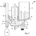
- FIG. 2 a second operating state of the device 100 is shown, in which the valve 3 is closed and, accordingly, the connection between the filling product reservoir 1 and the product channel 2 is closed.
- the metering piston 40 is in the downward movement, so the fill product then received in the metering cylinder 4 flows via the product channel 2 and in particular the siphon-like section 20 at the connection opening 22 into the discharge channel 5 and then enters the schematically indicated container 110 to be filled through the outlet end 52.
- the Austechstumbleel 50 is in an extended upward position so that it is substantially flush with the upper edge of the connection opening 22. The filling product accordingly flows unhindered through the discharge channel 5 into the container 110 to be filled.
- the Ausschubkanal 5 is again controlled in the lowered position, as in FIG. 1 is shown, wherein the filling product, which is still in Ausschubkanal 5 at this time, is pushed out through the outlet end 52. Accordingly, the Ausschubkanal 5 is completely emptied of the filling product, so that a defined filling of the container to be filled 110 is achieved.
- particles or particles such as fruit pieces, whole fruits, chocolate, muesli or other solids
- a shearing off of the respective particles located in this area will take place, that the particles are not crushed, but have a clean cut edge. This is particularly important when filling filling products with larger pieces of fruit or whole elastic fruits, such as cherries, because the particles present in the filling product are then not crushed, but only a few clean cut particles are present next to the whole particles.
- connection opening 22 is further closed, so that in the next cycle, the valve 3 can be opened and by raising the metering piston 40 of the metering cylinder 4 can be filled in turn with filling product from the Gundreservoir.
- This operating state is, for example, in FIG. 1 shown.
- the outlet end 52 can be kept closed in the absence of a container.
- the Austechsticideel 50 can be used as overload protection or overload indicator when the outlet end 52 is blocked, for example by blocked filling product or other foreign matter, so that the Ausret Congressel 50 would have to be lowered with too high a force.
- an overload by the blocking of the outlet end 52 and the mouth of Ausschubkanals 5 by, for example, a reaching into Ausschubkanal foreign bodies when exceeding a certain counterforce in the drive of Ausschield Terminels 50 no further movement longer possible, so that the possible mechanical damage of the device 100 in Limits is kept or can be completely avoided.
- an overload safety device can be easily integrated, which reports a blockage of the pushrod 50 via an electrosensitive feedback. Furthermore, a targeted control or selective control can be made in this way, which makes it possible to keep the Ausschubst Schemeel 50 in the closed position in the presence of a container gap to prevent the expulsion of filling product in a position in which there is no container.
- FIG. 3 the device 100 is shown during a cleaning process.
- the valve 3 is fully opened, such that a cleaning medium from the filling product reservoir 1 can flow through the annular gap of the valve 3 into the product channel 2.
- the metering piston 40 is completely lifted out of the metering cylinder 4, so that here too a complete cleaning of both the inner surfaces of the metering cylinder 4 and the outer surfaces of the metering piston 40 can be carried out in a simple manner by applying a cleaning medium.
- the discharge opening 28 and in particular the shut-off device at the discharge opening 28 are opened to allow a drainage of the cleaning medium. Since the discharge opening 28 is arranged at the lowest point in the product channel 2, can also be achieved accordingly that residual filling product as well as all cleaning medium can flow reliably and accordingly the cleaning can be carried out completely. Furthermore, it can be avoided that cleaning medium or rinsing water remain in the product channel 2, which could be problematic in a subsequent startup of the device 100 and could lead to carryover of the corresponding media.
- the device 100 and in particular its base body, on which, for example, the walls of the product channel 2, the walls of the filling product reservoir 1, the metering cylinder 4 and the Ausschubkanal 5 are provided, and for example in FIG. 3 shown, can not be ripped apart, but can persist in the configuration.
Landscapes
- Engineering & Computer Science (AREA)
- Mechanical Engineering (AREA)
- Basic Packing Technique (AREA)
Abstract
Description
- Die vorliegende Erfindung betrifft eine Vorrichtung zum Befüllen eines Behälters und insbesondere einen Kolbenfüller, der bevorzugt für den Einsatz in einer Rundläuferlebensmittelabfüllanlage vorgesehen ist.
- Zur Abfüllung von viskosen Lebensmitteln oder Getränken, insbesondere hochviskosen Lebensmitteln, wie beispielsweise Marmeladen, Joghurts, Ketschups, Mayonnaise, Sahne etc. ist es bekannt, die Abfüllung der hochviskosen Füllprodukte mittels Kolbenfüllern durchzuführen. Kolbenfüller werden auch zum Abfüllen von viskosen Füllprodukten verwendet, welche Feststoffanteile aufweisen wie beispielsweise Fruchtstücke, Schokoladenstücke, Cerealien oder andere Stücke, welche im Zusammenhang mit Lebensmitteln abgefüllt werden.
- Die Verwendung von Kolbenfüllern zur Abfüllung viskoser Füllprodukte hat den Vorteil, dass die sonst nicht oder nur sehr langsam ausfließenden viskosen Füllprodukte mit einer vorgegebenen Geschwindigkeit im Takt der jeweiligen Abfüllanlage in die zu befüllenden Behälter ausgegeben werden können. Weiterhin kann über die Verwendung des Dosierkolbens des Kolbenfüllers eine genau dosierte Abfüllung erreicht werden, so dass das Füllprodukt in den zu befüllenden Behälter mit dem vorgesehenen Füllvolumen, dem vorgesehen Füllgewicht oder der vorgesehenen Füllhöhe eingegeben werden kann.
- Kolbenfüller sind in unterschiedlichen Konfigurationen bekannt. Aus der
DE 24 53 312 A1 ist beispielsweise ein Rundläuferkolbenfüller bekannt, bei welchem die Steuerung des Füllproduktstromes von einem Füllproduktreservoir in den Dosierzylinder über einen mit einer entsprechenden Ventilöffnung versehenen Plunger gesteuert wird. Der Plunger dient hier sowohl als Ventil zum Steuern des Füllproduktstromes als auch als Ausschubstößel, um Füllproduktreste aus dem Ausschubkanal auszustoßen. - Aus der
JP 200-308470 A1 - Weiterhin bekannt ist, beispielsweise unter der Bezeichnung Viscofill V der KRONES AG, ein Kolbenfüller, welcher zur Steuerung des Füllproduktstromes aus einem Füllproduktreservoir in einen Ausschubkanal ein Drehventil verwendet, welches eine vertikal angeordnete Drehachse aufweist.
- Weiterhin bekannt ist, beispielsweise unter der Bezeichnung Viscofill S der KRONES AG, ein Kolbenfüller, bei welchem im Boden des Füllproduktbehälters ein pneumatisch angetriebenes Sitzventil zur Steuerung des Füllproduktstromes aus dem Füllproduktreservoir in den Dosierzylinder vorgesehen ist und unterhalb des Dosierzylinders ein weiteres Sitzventil vorgesehen ist, durch welches hindurch ein Ausströmen des Füllprodukts in den zu befüllenden Behälter stattfinden kann.
- Bei den bekannten Kolbenfüllern, welche Drehventile mit vertikaler oder horizontaler Ausrichtung aufweisen, ist die Reinigung aufwändig, da das jeweilige Drehventil für jeden Reinigungsvorgang vollständig aus seinem Ventilsitz herausgenommen werden muss, etwa durch das Herausziehen des Drehventils aus einem entsprechenden Drehventilgehäuse. Weiterhin werden die Drehventile je Dosiervorgang zweimal um ca. 180° gedreht, so dass hier je nach abgefülltem Füllprodukt ein erhöhter Verschleiß vorliegen kann.
- Weiterhin liegen bei den bekannten Systemen die Durchgangsöffnungen zu den jeweiligen Dosierzylindern in der Zarge des Produkttrichters. Daher kann das Produkt nur bis maximal zur Oberkante der Durchgangsöffnungen in den Dosierzylinder angesaugt werden, so dass es notwendig sein kann, das sich im Bodenbereich des jeweiligen Füllproduktreservoirs befindliche Füllprodukt am Ende des Füllvorganges zu verwerfen.
- Bei den bekannten Kolbendosierern mit Sitzventilen wird der freie Durchgangsdurchmesser für das einzudosierende Füllprodukt durch die Ringspalte in den Ventilen bestimmt, so dass der maximale Partikeldurchmesser begrenzt ist. Weiterhin kann durch das Vorsehen des Sitzventils am Füllproduktauslauf beim Abfüllen von Füllprodukten mit Stückchen ein definiertes Abtrennen der Stückchen nicht erreicht werden. Vielmehr können Stückchen im Sitz des Ventils zwischen dem Ventilkörper und dem Ventilsitz eingeklemmt werden beziehungsweise zerquetscht werden, worunter die Füllproduktqualität leiden kann und ein Nachtropfen beziehungsweise unkontrolliertes Abfallen des eingequetschten Stückchenrests auftreten kann.
- Ausgehend von dem genannten Stand der Technik ist es eine Aufgabe der vorliegenden Erfindung, eine Vorrichtung zum Befüllen eines Behälters mit einem viskosen Füllprodukt anzugeben, welche gegenüber den aus dem Stand der Technik bekannten Vorrichtungen verbesserte Eigenschaften aufweist.
- Diese Aufgabe wird durch eine Vorrichtung mit den Merkmalen des Anspruchs 1 gelöst. Vorteilhafte Weiterbildungen ergeben sich aus den Unteransprüchen.
- Entsprechend wird eine Vorrichtung zum Befüllen eines Behälters mit einem Füllprodukt, bevorzugt zum Befüllen mit einem viskosen und partikelhaltigen Füllprodukt, vorgeschlagen, umfassend ein Füllproduktreservoir zur Aufnahme des abzufüllenden Füllprodukts, einen Dosierzylinder mit einem darin verschiebbar aufgenommenen Dosierkolben zum Dosieren des Füllprodukts, und einem Ausschubkanal mit einem Auslassende zum Auslassen des Füllprodukts in den zu befüllenden Behälter, wobei in dem Ausschubkanal ein Ausschubstößel zum Ausschieben eines Produktrests am Ende des Befüllvorganges angeordnet ist, und das Füllproduktreservoir, der Dosierzylinder und der Ausschubkanal über einen gemeinsamen Produktkanal miteinander kommunizieren. Erfindungsgemäß ist im Boden des Füllproduktreservoirs ein Ventil zum Öffnen und Schließen der Verbindung zwischen Füllproduktreservoir und Produktkanal angeordnet.
- Dadurch, dass in der Vorrichtung im Boden des Füllproduktreservoirs ein Ventil zum Öffnen und Schließen der Verbindung zwischen dem Füllproduktreservoir und dem Produktkanal angeordnet ist und gleichzeitig am Füllproduktauslauf ein Ausschubkanal mit einem Ausschubstößel vorgesehen ist, können viskose Füllprodukte schonend und exakt abgefüllt werden. Insbesondere können Füllprodukte, in welchen Stückchen vorliegen, insbesondere große, deformierbare Stückchen, wie beispielsweise Kirschen, mit der beschriebenen Vorrichtung schonend und exakt abgefüllt werden.
- Die Nachteile der bekannten Kolbenfüller, welche mit zwei Sitzventilen versehen sind, werden durch das Bereitstellen des Ausschubkanals mit dem Ausschubstößel überwunden, da an den durch den Ausschubstößel bereitgestellten Scherflächen ein exaktes und sauberes Abtrennen beziehungsweise Durchtrennen der Stückchen beim Verschließen des Ausschubkanals mittels des Ausschubstößels stattfindet. Entsprechend findet ein Zerquetschen der Stückchen nicht mehr statt, so dass eine hohe Produktqualität erreicht wird, und insbesondere sich im befüllten Behälter keine zerquetschten oder undefiniert abgetrennten Stückchen mehr befinden.
- Weiterhin lässt sich die Vorrichtung auch auf einfache Weise reinigen, da der aufwändige Prozess des Auseinanderbauens der Drehventile nicht mehr anfällt. Vielmehr kann das im Boden des Füllproduktreservoirs angeordnete Sitzventil auf herkömmliche Weise mittels Reinigungsmedien gespült werden, ohne dass es hier eines Auseinanderbaus der Vorrichtung bedürfe. Anders als bei einem Drehventil kann ein geöffnetes Sitzventil nämlich mit allen seinen produktberührten Oberflächen vollständig von dem Reinigungsmedium umströmt werden, ohne dass ein Auseinanderbauen der Vorrichtung vonnöten wäre.
- Der Ausschubkanal sowie der Ausschubstößel können ebenfalls in bekannter Weise einfach gespült werden, ohne dass hier ein aufwändiges Auseinanderbauen vonnöten wäre. Der Ausschubstößel kann einfach aus dem Ausschubkanal herausgezogen werden, so dass sämtliche produktberührten Flächen hier gespült werden können, ohne dass die gesamte Vorrichtung in aufwändiger Weise demontiert werden muss.
- Weiterhin ist das Verschleißverhalten der Vorrichtung verbessert, da anstelle des verschleißanfälligen Drehventils ein verschleißarmes Sitzventil verwendet werden kann.
- Darüber hinaus ist dadurch, dass das Ventil im Boden des Füllproduktreservoirs angeordnet ist, sichergestellt, dass sämtliches Füllprodukt, welches sich im Füllproduktreservoir befindet, durch das Ventil im Boden des Füllproduktreservoirs auslaufen kann und in die Behälter dosiert werden kann. Der verbleibende Füllproduktrest ist lediglich durch die Anhaftung des Füllprodukts aufgrund der hohen Viskosität im Füllproduktreservoir bedingt, nicht aber durch eine Entnahmeposition des Füllprodukts derart, dass zwangsläufig immer ein Füllproduktrest im Füllproduktreservoir verbleibt, welcher durch die Höhe der Entnahmeöffnung definiert ist.
- Bevorzugt ist das Ventil ein Sitzventil und/oder ein Tellerventil und das Ventil weist bevorzugt einen Ventilteller auf, welcher in einen in einer im Boden des Füllproduktreservoirs angeordneten Öffnung angeordneten Ventilsitz abdichtend absenkbar ist. Auf diese Weise kann eine zuverlässige Ausbildung des Ventils erreicht werden, welche weiterhin einfach reinigbar ist.
- Eine individuelle Ansteuerung des Ventils lässt sich dadurch erreichen, dass das Ventil mit einem mechanischen, pneumatischen, elektropneumatischen, elektromotorischen oder elektromagnetischen Antrieb individuell angesteuert ist.
- Ein unkontrolliertes Auslaufen des Füllprodukts kann darüber vermieden werden, dass der Ausschubkanal über einen siphonartigen Abschnitt des Produktkanals mit dem Dosierzylinder in Kommunikation steht. Dabei verjüngt sich der siphonartige Abschnitt von seinem dem Dosierzylinder zugewendeten Ende zu seinem dem Ausschubkanal zugewendeten Ende hin bevorzugt und ist besonders bevorzugt sich stetig verjüngend ausgebildet.
- Um ein Eintreten von Luft in den Ausschubkanal und in den siphonartigen Abschnitt des Produktkanals zu vermeiden oder zu reduzieren, ist bevorzugt eine untere Sperrkante des siphonartigen Abschnitts des Produktkanals auf einem Niveau unterhalb des durch den unteren Totpunkt des Dosierkolbens definierten Niveaus angeordnet. Auf diese Weise kann erreicht werden, dass Luft auch nicht in den Ausschubkanal gelangt, in welchem ein ungenaues Dosieren beziehungsweise ein Spritzen bei Austreten der Luftblase durch eine Auslassöffnung beim Befüllen des zu befüllenden Behälters auftritt, so dass auf diese Weise ein exakteres und sauberes Befüllen des zu befüllenden Behälters erreicht werden kann.
- Um ein Akkumulieren von Luft in dem Dosierkolben oder dem gemeinsamen Produktkanal zu verhindern beziehungsweise zu reduzieren, liegt die Öffnung im Boden des Füllproduktreservoirs bevorzugt auf einem höheren Niveau, als das von dem Dosierkolben in seinem unteren Totpunkt gebildete Niveau. Auf diese Weise kann Luft, welche sich im Dosierzylinder oder im Produktkanal ansammelt, über ein geöffnetes Ventil im Boden des Füllproduktreservoirs wieder in das Füllproduktreservoir zurückfließen werden. Auf diese Weise wird sichergestellt, dass der gemeinsame Produktkanal und der Dosierzylinder entsprechend bei jedem Dosiervorgang entlüftet werden, so dass sich die gesamte Luftmenge, welche sich in dem System ansammelt, gering gehalten wird oder das Ansammeln gar vermieden werden kann.
- Besonders bevorzugt befindet sich im Boden des Produktkanals eine Ablassöffnung, welche mittels eines Absperrorgans verschließbar ist. So kann erreicht werden, dass bei einer Reinigung der Vorrichtung ein vollständiges Auslaufen des Reinigungsmediums auch aus dem gemeinsamen Produktkanal, insbesondere einem gemeinsamen Produktkanal, welcher eine siphonartige Ausbildung aufweist, erreicht wird, so dass der gemeinsame Produktkanal genauso wie der Ausschubkanal und der Dosierzylinder vollständig von dem Reinigungsmedium entleert werden kann. Die Öffnung mit dem Absperrorgan bildet dabei zumindest für die jeweilige individuelle Vorrichtung den tiefsten Punkt, so dass das Reinigungsmedium vollständig auslaufen kann.
- Zur individuellen Ansteuerung ist der Ausschubstößel bevorzugt mit einem mechanischen, pneumatischen, elektropneumatischen, elektromotorischen oder elektromagnetischen Antrieb individuell angesteuert. Dabei kann besonders bevorzugt eine Ansteuerung des Antriebs so eingerichtet sein, dass der Ausschubstößel bei Vorliegen einer Behälterlücke in der abgesenkten Position verbleibt.
- Bevorzugt ist zwischen dem siphonartigen Abschnitt des Produktkanals und dem Ausschubkanal eine Scherkante ausgebildet, welche mit dem Ausschubstößel zusammenwirkt. Mittels der Scherkante kann beim Absenken des Ausschubstößels ein definiertes Abscheren von Füllproduktbestandteilen, insbesondere Füllproduktpartikeln erreicht werden, so dass ein sauberes und quetschfreies Abfüllergebnis erreicht wird.
- In einer weiteren bevorzugten Ausgestaltung ist bei einer Reinigung der Vorrichtung das Ventil in die geöffnete Stellung gesteuert und der Ausschubstößel aus dem Ausschubkanal ausgezogen sowie der Dosierkolben aus dem Dosierzylinder ausgezogen. Es findet insbesondere kein Auseinanderbauen von Gehäuseteilen statt, so dass eine einfache Reinigung durchgeführt werden kann.
- Bevorzugte weitere Ausführungsformen und Aspekte der vorliegenden Erfindung werden durch die nachfolgende Beschreibung der Figuren näher erläutert. Dabei zeigen:
- Figur 1
- eine Vorrichtung zum Befüllen eines Behälters in einem ersten Betriebszustand beim Befüllen des Dosierzylinders mit Füllprodukt aus dem Füllproduktreservoir;
- Figur 2
- die Vorrichtung der
Figur 1 in einem zweiten Betriebszustand, in welchem der Dosierzylinder das Füllprodukt über den Ausschubkanal in den zu befüllenden Behälter ausgibt und - Figur 3
- die Vorrichtung der
Figuren 1 und2 in einem dritten Zustand, in welchem eine Reinigung der Vorrichtung durchgeführt wird. - Im Folgenden werden bevorzugte Ausführungsbeispiele anhand der Figuren beschrieben. Dabei werden gleiche, ähnliche oder gleichwirkende Elemente in den unterschiedlichen Figuren mit identischen Bezugszeichen bezeichnet und auf eine wiederholte Beschreibung dieser Elemente wird verzichtet, um Redundanzen zu vermeiden.
-
Figur 1 zeigt eine Vorrichtung 100 zum Befüllen eines schematisch angedeuteten Behälters 110 mit einem viskosen Füllprodukt, insbesondere einem hochviskosen Füllprodukt, welches mit Partikeln oder Stückchen versetzt ist, beispielsweise ein Joghurt mit ganzen Kirschen. Das viskose Füllprodukt wird in einem Füllproduktreservoir 1, welches Seitenwände 10 und einen Boden 12 aufweist, zur Abfüllung bereitgestellt. Das Füllproduktreservoir 1 kann beispielsweise ein Produktkessel eines Rundläuferfüllers in einer Abfüllanlage sein, wobei dann typischer Weise eine Mehrzahl von Vorrichtungen 100 als Füllorgane am Umfang des Füllproduktreservoirs 1 angeordnet sind und mit diesem im Produktionsbetrieb umlaufen. - Im Boden 12 des Füllproduktreservoirs 1 ist eine Öffnung 14 vorgesehen, durch welche hindurch das Füllprodukt in einen Produktkanal 2 einfließen kann. Die Öffnung 14 ist durch ein Ventil 3 verschließbar. Das Ventil 3 weist in dem gezeigten Ausführungsbeispiel einen Ventilteller 30 und einen um die Öffnung 14 im Boden 12 des Füllproduktreservoirs 1 umlaufenden Ventilsitz 32 auf. Der Ventilteller 30 kann abdichtend in den Ventilsitz 32 abgesenkt werden oder aus dem Ventilsitz 32 herausgehoben werden, um dann entsprechend die Öffnung 14 im Boden 12 des Füllproduktreservoirs 1 zu öffnen und einen Strom des Füllprodukts aus dem Füllproduktreservoir 1 in den Produktkanal 2 zu ermöglichen.
- Die Verwendung des Sitzventils 3 ist weniger verschleißanfällig, als die aus dem Stand der Technik bekannten Drehventile, so dass die Vorrichtung 100 verschleißärmer ausgebildet ist.
- Weiterhin ist der mechanische Aufwand, der getrieben werden muss, um die Vorrichtung 100 aufzubauen, ist weit geringer als in den aus dem Stand der Technik bekannten Vorrichtungen, so dass zum einen die Kosten und die bewegte Masse gesenkt werden können, und zum anderen die Betriebssicherheit verbessert werden können.
- Darüber hinaus ermöglicht es die Montage des Ventils 3 im Boden 12 des Füllproduktreservoirs 1, dass das Füllprodukt vollständig aus dem Füllproduktreservoir 1 abgezogen werden kann.
- Der Ventilteller 30 ist über einen Ventilstößel 34 mit einem Ventilantrieb 36 verbunden, wobei der Ventilantrieb 36 ein mechanischer, pneumatischer, elektropneumatischer, elektromotorischer oder elektromagnetischer Antrieb sein kann, welcher ein zuverlässiges Öffnen und Schließen des Ventils 3 ermöglicht und gleichzeitig auch ein individuelles Ansteuern jedes Ventils 3 beispielsweise in einem Rundläuferfüller ermöglicht.
- Der Produktkanal 2, der sich von der mittels des Ventils 3 verschließbaren Öffnung 14 des Füllproduktreservoirs 1 ausgehend erstreckt, kommuniziert mit einem Dosierzylinder 4, in welchem ein Dosierkolben 40 angeordnet ist. Der Dosierkolben 40 kann innerhalb des Dosierzylinders 4 auf und ab bewegt werden und auf diese Weise entsprechend eine Volumenveränderung des im Dosierzylinder 4 aufgenommenen Volumens bereitstellen. Durch ein Anheben des Dosierkolbens 40 im Dosierzylinder 4, sowie durch den Pfeil in der
Figur 1 angedeutet, kann entsprechend Füllprodukt aus dem Füllproduktreservoir 1 durch das geöffnete Ventil 3 und die Öffnung 14 im Boden 12 des Füllproduktreservoirs durch den Produktkanal 2 in den Dosierzylinder 4 eingesaugt werden. Der auf diese Weise bereitgestellte Strom des Füllprodukts aus dem Füllproduktreservoir in den Dosierzylinder 4 ist in derFigur 1 mit Pfeilen angedeutet. - Weiterhin ist ein Ausschubkanal 5 vorgesehen, welcher über einen siphonartigen Abschnitt 20 des Produktkanals 2 mit dem Dosierzylinder 4 kommuniziert. In dem in
Figur 1 gezeigten Betriebszustand der Vorrichtung 100 ist der Ausschubkanal 5 durch einen darin abgesenkten Ausschubstößel 50, welcher auch als Plunger bezeichnet wird, verschlossen. Der Ausschubstößel 50 ist dabei bis zum Auslassende 52 des Ausschubkanals 5 vorgeschoben und füllt entsprechend den Ausschubkanal 5 in diesem Betriebszustand vollkommen aus. - Der siphonartige Abschnitt 20 des Produktkanals 2 ist mit dem Ausschubkanal 5 über eine Verbindungsöffnung 22 verbunden, welche es dem Füllprodukt ermöglicht, bei entferntem Ausschubstößel 50 durch den Ausschubkanal 5 zu dem Auslassende 52 zu gelangen, um dann in den zu befüllenden Behälter 110 zu gelangen. Dieser Betriebszustand ist auch in
Figur 2 gezeigt. - Die Ausbildung des Produktkanals 2 mit dem siphonartigen Abschnitt 20 verhindert ein unkontrolliertes Leerlaufen von Produkt in den zu befüllenden Behälter 110.
- An der Verbindung des siphonartigen Abschnitts 20 des Produktkanals 2 mit dem Ausschubkanal 5 ist im Bereich der Verbindungsöffnung 22 entsprechend Verschneidung ausgebildet, welche eine Scherkante 54 bereitstellt. An der Scherkante 5 kann der sich absenkende Ausschubstößel 50 eine Scherfunktion ausüben, mittels welcher ein Abscheren von Füllprodukt, insbesondere partikelförmigem Füllprodukt, ermöglicht wird. Insbesondere wird auf diese Weise ermöglicht, flexible, größervolumige Füllproduktstücke, wie beispielsweise Kirschen, an der Scherkante 54 mittels des Ausschubstößels 50 sauber abzuscheren, so dass ein Zerquetschen dieser Füllproduktstücke nicht stattfindet und ein sauberes und definiertes Ausschieben des Füllprodukts durch das Auslassende 52 in den darunter angeordneten zu befüllenden Behälter 110 ermöglicht wird.
- Die Öffnung 14 im Boden 12 des Füllproduktreservoirs 1 ist auf einem höheren Niveau h1 angeordnet, als die untere Kante des Dosierzylinders 4, welche gleichzeitig auch einen unteren Kolbentotpunkt des Dosierkolbens 40 darstellt. Auf diese Weise kann erreicht werden, dass Luft, welche möglicherweise im Dosierzylinder 4 aufgenommen ist oder sich in diesem ansammelt, durch den Dosierkolben 40 beim Ausstoßen, also der Abwärtsbewegung des Dosierkolbens 40 innerhalb des Dosierzylinders 4 aus dem Dosierzylinder 4 herausgetrieben wird. Da beim Ausstoßen des Füllprodukts das Ventil 3 üblicher Weise geschlossen ist, sammelt sich die aus dem Dosierkolben 4 ausgestoßene Luft dann unter dem geschlossenen Ventil 3 an. Bei der nächsten Öffnung des Ventils 3, beispielsweise im nächsten Füllzyklus, kann dann die Luft durch das Ventil 3 in das Füllproduktreservoir 1 zurückgedrückt werden. Entsprechend kann eine Akkumulierung von Luft im Dosierzylinder 4 reduziert beziehungsweise unterbunden werden.
- Der siphonartige Abschnitt 20 des Produktkanals 2 weist eine untere Sperrkante 24 auf, welche ein Niveau h3 aufweist, welches unterhalb des untersten Kolbentotpunkts des Dosierkolbens 40 liegt, welcher mit dem Niveau h2 gekennzeichnet ist. Auf diese Weise kann sichergestellt werden, dass Luft, welche aus dem Dosierzylinder 4 mittels des Dosierkolbens 40 bei einer Abwärtsbewegung des Dosierkolbens 40 ausgeschoben wird, nicht in den siphonartigen Abschnitt 20 des Produktkanals 2 aufsteigt, sondern über die sowohl oberhalb der unteren Sperrkante 24 als auch oberhalb des unteren Kolbentotpunkts des Dosierkolbens 40 liegende Öffnung 14 im Boden 12 des Füllproduktreservoirs 1 in das Füllproduktreservoir 1 zurückströmen kann beziehungsweise in dieses zurückgedrückt wird. Ein Eintreten von Luft in den siphonartigen Abschnitt 20 und damit auch in den Ausschubkanal 5 wird auf diese Weise reduziert beziehungsweise vollständig unterbunden. Damit kann ein sauberes Abfüllen des Füllprodukts erreicht werden, insbesondere dadurch, dass aus dem Auslassende 52 kein Gemisch aus Luft und Füllprodukt austritt, welches zu einer erhöhten Spritzneigung des Füllprodukts beim Abfüllen führen könnte. Weiterhin kann auf diese Weise ein zuverlässiges Abfüllen eines definierten Volumens sichergestellt werden, welches nicht durch das Vorliegen einer größeren Luftblase kompromittiert wird.
- Im Bodenbereich 26 des Produktkanals 2 ist eine Ablassöffnung 28 vorgesehen, die mittels eines entsprechenden Sperrorganes im Produktionsbetrieb verschlossen ist. Die Ablassöffnung 28 ist bevorzugt an der tiefsten Position des Produktkanals 2 vorgesehen und ermöglicht es, nach Abschluss eines Produktionszyklus sich noch im Produktkanal 2 befindliches Füllprodukt abzulassen und/oder ein Reinigungsmedium, welches zur Reinigung der Vorrichtung 100 verwendet wurde, vollständig abzulassen. So kann ein Produktwechsel oder ein Produktionsstillstand mit jeweils nachfolgender Reinigung ohne die Gefahr einer Verschleppung des jeweils verwendeten Reinigungsmediums oder der vorhergehenden Füllprodukts durchgeführt werden und die Vorrichtung 100 kann ab dem ersten Behälter des nachfolgenden Produktzyklus sortenrein abfüllen.
- Die Bewegung des Ausschubstößels 50 wird in dem gezeigten Ausführungsbeispiel über eine Führungsschiene 56 gesteuert, an welcher eine entsprechende Rolle des Ausschubstößels 50 geführt ist. Der Ausschubstößel 50 kann aber auch mit beliebigen anderen Antrieben ausgestattet sein, insbesondere auch mit einem individuellen pneumatischen, hydraulischen, elektrischen, magnetischen oder anders gearteten Antrieb, welcher sich individuell ansteuern lässt.
- Durch das Verwenden des Ventils 3 in Form eines Tellerventils mit Ventilteller 30 in Kombination mit einer entsprechenden Ausprägung des Ventilsitzes 32 sowie der Ausgestaltung des Füllproduktreservoirs 1 im Bereich seines Bodens 2 in Form eines Trichters kann erreicht werden, dass der Ringspalt, welcher zwischen dem Ventilteller 30 und dem Ventilsitz 32 ausgebildet wird, deutlich größer ist, als der welcher durch die im Stand der Technik verwendeten Sitzventile, welche kleinere Ventilkörper verwenden, bereitgestellt wird. Hierdurch kann sichergestellt werden, dass auch Füllprodukte mit größeren Partikeln, insbesondere größeren elastischen Partikeln wie beispielsweise Kirschen, den Ringspalt problemlos passieren können und entsprechend durch die Öffnung 14 im Boden 12 des Füllproduktreservoirs 1 in den Produktkanal 2 eintreten können.
- Der Produktkanal 2 weist im Bereich der Öffnung 14 im Boden 12 des Füllproduktreservoirs 1 einen größeren Querschnitt q1 auf, als im Bereich der Verbindungsöffnung 22, in welcher ein Querschnitt q2 vorgesehen ist. Die Verringerung des Querschnitts von dem größeren Öffnungsquerschnitt q1 bei der Öffnung 14 im Boden 12 des Füllproduktreservoirs 1 hin zur Verbindungsöffnung 22 mit dem reduzierten Querschnitt q2 und schließlich zum Querschnitt q3 an dem Auslassende 52 des Ausschubkanals 5 findet im Wesentlichen stetig statt, so dass ein Stauen des Füllprodukts oder ein übermäßiges Quetschen beziehungsweise die Ausübung eines übermäßig hohen Druckes auf das Füllprodukt auf diese Weise vermieden werden kann. Bevorzugt ist die Querschnittsverringerung von der Öffnung 14 hin zur Verbindungsöffnung 22 im Wesentlichen linear ausgebildet. Der Füllproduktkanal 2 wird dabei im Bereich des Dosierzylinders 4 nach oben hin durch den vollständig in seinem unteren Totpunkt abgesenkten Dosierkolben 40 abgegrenzt.
- Zumindest der siphonartige Abschnitt 20 des Produktkanals 2 weist von seinem Beginn an einen sich stetig verringernden Querschnitt hin zur Verbindungsöffnung 22 auf, so dass das Füllprodukt in diesem Bereich nicht übermäßig gestaut beziehungsweise gequetscht wird und entsprechend eine schonende Füllproduktabfüllung erreicht werden kann.
- Die Reduktion des Querschnitts auf den Querschnitt q3 am Auslassende 42 des Ausschubkanals 5 ist vonnöten, um ein Abfüllen zu erreichen, welches mit dem Mündungsquerschnitt des zu befüllenden Behälters 110 korrespondiert und gleichzeitig aber ein adäquates Füllproduktvolumen in dem Dosierzylinder 4 aufnehmen zu können, ohne eine übermäßige Bauhöhe der Vorrichtung 100 zu erreichen. Hierfür ist ein größerer Querschnitt des Dosierzylinders 4 und damit auch der Öffnung 14 vonnöten.
- In
Figur 2 ist ein zweiter Betriebszustand der Vorrichtung 100 gezeigt, in welchem das Ventil 3 geschlossen ist und entsprechend die Verbindung zwischen dem Füllproduktreservoir 1 und dem Produktkanal 2 geschlossen ist. Der Dosierkolben 40 befindet sich in der Abwärtsbewegung, so dass das dann in dem Dosierzylinder 4 aufgenommene Füllprodukt über den Produktkanal 2 und insbesondere den siphonartigen Abschnitt 20 an der Verbindungsöffnung 22 in den Ausschubkanal 5 strömt und dann durch das Auslassende 52 in den schematisch angedeuteten, zu befüllenden Behälter 110 eintritt. Der Ausschubstößel 50 befindet sich dabei in einer nach oben hin ausgezogenen Position, so dass er im Wesentlichen mit der oberen Kante der Verbindungsöffnung 22 abschließt. Das Füllprodukt strömt entsprechend ungehindert durch den Ausschubkanal 5 in den zu befüllenden Behälter 110. - Ist der Dosierkolben 40 in der unteren Totposition angelangt, so dass ein weiteres Fördern von Füllprodukt durch den Produktkanal 2 nicht mehr stattfindet, wird der Ausschubstößel 50 wieder in die abgesenkte Position gesteuert, so wie sie in
Figur 1 gezeigt ist, wobei das Füllprodukt, welches sich zu diesem Zeitpunkt noch im Ausschubkanal 5 befindet, durch das Auslassende 52 ausgeschoben wird. Entsprechend wird der Ausschubkanal 5 vollständig von dem Füllprodukt geleert, so dass eine definierte Füllung des zu befüllenden Behälters 110 erreicht wird. - Befinden sich in dem Füllprodukt Stückchen oder Partikel, so wie beispielsweise Fruchtstücke, ganze Früchte, Schokolade, Müsli oder andere Feststoffe, so wird während des Absenkens des Ausschubstößels 50 an der Scherkante 54 ein Abscheren der jeweils sich in diesem Bereich befindlichen Partikel stattfinden, derart, dass die Partikel nicht zerquetscht werden, sondern eine saubere Schnittkante aufweisen. Dies ist insbesondere beim Abfüllen von Füllprodukten mit größeren Fruchtstücken oder ganzen elastischen Früchten, wie beispielsweise Kirschen, von Bedeutung, da die im Füllprodukt vorliegenden Partikel dann nicht zerquetscht sind, sondern lediglich einige sauber geschnittene Partikel neben den ganzen Partikeln vorliegen.
- Durch das Absenken des Ausschubstößels 50 in den Ausschubkanal 5 wird weiterhin die Verbindungsöffnung 22 verschlossen, so dass im nächsten Zyklus das Ventil 3 geöffnet werden kann und durch Anheben des Dosierkolbens 40 der Dosierzylinder 4 wiederum mit Füllprodukt aus dem Füllproduktreservoir befüllt werden kann. Dieser Betriebszustand ist beispielsweise in
Figur 1 gezeigt. - Bei einer individuellen Ansteuerung des Ausschubstößels 50 kann weiterhin erreicht werden, dass in einer Produktionsanlage bei Vorliegen einer Behälterlücke, also beim Fehlen eines Behälters unterhalb des Auslassendes 52 im Produktionsbetrieb, der Ausschubstößel 50 über den gesamten Zyklus hinweg in der abgesenkten Position verbleibt, so dass Füllprodukt nicht ausgestoßen wird.
- So kann verhindert werden, dass Füllprodukt die Umgebung verschmutzt, da es nicht von einem zu befüllenden Behälter aufgefangen wird. Entsprechend kann das Auslassende 52 bei Nichtvorliegen eines Behälters verschlossen gehalten werden.
- Weiterhin kann der Ausschubstößel 50 als Überlastsicherung oder Überlastindikator verwendet werden, wenn das Auslassende 52 beispielsweise durch verblocktes Füllprodukt oder andere Fremdkörper blockiert ist, so dass der Ausschubstößel 50 mit einer zu hohen Kraft abgesenkt werden müsste. Bei einer Überlast durch die Verblockung des Auslassendes 52 beziehungsweise der Mündung des Ausschubkanals 5 durch beispielsweise einem in den Ausschubkanal reichenden Fremdkörpern wird bei Überschreitung einer bestimmten Gegenkraft im Antrieb des Ausschubstößels 50 keine weitere Bewegung mehr möglich, so dass die mögliche mechanische Beschädigung der Vorrichtung 100 in Grenzen gehalten wird beziehungsweise vollständig vermieden werden kann. Bei einer Überwachung der Position des Ausschubstößels 50 an vorgegebenen Positionen am Umfang der rotierenden Vorrichtung kann so festgestellt werden, ob in einer individuellen Vorrichtung 100, also einem bestimmten Füllorgan, ein solcher Fehler vorliegt. Der Fehler kann dann entsprechend der jeweiligen Vorrichtung 100 eindeutig zugeordnet werden und entsprechend nach einem Anhalten der Anlage zielgerichtet behoben werden.
- Bei einer elektromagnetischen beziehungsweise elektromotorischen Ansteuerung beziehungsweise Antrieb des Ausschubstößels 50 kann eine Überlastsicherung einfach integriert werden, welche über eine elektrosensorische Rückmeldung eine Blockage des Ausschubstößels 50 meldet. Weiterhin kann auf diese Weise eine gezielte Ansteuerung beziehungsweise selektive Ansteuerung vorgenommen werden, welche es ermöglicht, bei Vorliegen einer Behälterlücke den Ausschubstößel 50 in der geschlossenen Position zu halten, um das Ausschieben von Füllprodukt in einer Position, in welcher kein Behälter vorliegt, zu verhindern.
- In
Figur 3 ist die Vorrichtung 100 während eines Reinigungsvorganges gezeigt. Dabei ist das Ventil 3 vollständig geöffnet, derart, dass ein Reinigungsmedium aus dem Füllproduktreservoir 1 durch den Ringspalt des Ventils 3 in den Produktkanal 2 strömen kann. Weiterhin ist der Dosierkolben 40 vollständig aus dem Dosierzylinder 4 herausgehoben, so dass auch hier eine vollständige Reinigung sowohl der Innenoberflächen des Dosierzylinders 4 als auch der Außenoberflächen des Dosierkolbens 40 auf einfache Weise durch Beaufschlagen mit einem Reinigungsmedium durchgeführt werden kann. Weiterhin ist auch der Ausschubstößel 50 aus dem Ausschubkanal 5 vollständig herausgehoben, so dass hier ebenfalls durch eine einfache Beaufschlagung mit dem Reinigungsmedium sowohl der Ausschubkanal 5 als auch der Ausschubstößel 50 zumindest an den entsprechenden produktberührten Oberflächen gereinigt werden kann. - Die Ablassöffnung 28 und insbesondere die Absperrvorrichtung an der Ablassöffnung 28 sind geöffnet, um ein Abfließen des Reinigungsmediums zu ermöglichen. Da die Ablassöffnung 28 am tiefsten Punkt in dem Produktkanal 2 angeordnet ist, kann entsprechend auch erreicht werden, dass restliches Füllprodukt genauso wie alles Reinigungsmedium zuverlässig ausfließen können und entsprechend die Reinigung vollständig durchgeführt werden kann. Weiterhin kann vermieden werden, dass Reinigungsmedium oder Spülwasser im Produktkanal 2 verbleiben, welche bei einem nachfolgenden Anfahren der Vorrichtung 100 problematisch sein könnten und zu einer Verschleppung der entsprechenden Medien führen könnten.
- Zur Reinigung des Ventils 3 ist es nicht notwendig, dieses zu zerlegen, so wie es bei den Drehventilen des Standes der Technik der Fall ist, sondern aufgrund der Möglichkeit der vollständigen Umströmung der produktberührten Oberflächen des Ventils 3 ist es möglich, die Reinigung mit in der Vorrichtung 100 aufgenommenem, aber geöffnetem Ventil 3 zu ermöglichen.
- Weiterhin muss die Vorrichtung 100 und insbesondere deren Grundkörper, an welchem beispielsweise die Wände des Produktkanals 2, die Wände des Füllproduktreservoirs 1, der Dosierzylinder 4 und der Ausschubkanal 5 vorgesehen sind, sowie beispielsweise in
Figur 3 gezeigt, nicht auseinandergefahren werden, sondern kann in der Konfiguration bestehen bleiben. Insbesondere ist es möglich, diese Komponenten einstückig beziehungsweise in einem fest miteinander verbundenen, beispielsweise verschraubten oder verschweißten Zustand auch während der Reinigung zu halten. Entsprechend kann auf die zeitaufwändige Reinigung, welche aus dem Stand der Technik bekannt ist, bei welcher unterschiedliche Ebenen der Vorrichtung 100 auseinandergefahren werden müssen, verzichtet werden. - Soweit anwendbar können alle Merkmale, die in den einzelnen Ausführungsbeispielen dargestellt sind, miteinander kombiniert und/oder ausgetauscht werden, ohne den Bereich der Erfindung zu verlassen.
-
- 1
- Füllproduktreservoir
- 10
- Seitenwand
- 12
- Boden
- 14
- Öffnung
- 100
- Vorrichtung
- 110
- Behälter
- 2
- Produktkanal
- 20
- siphonartiger Abschnitt
- 22
- Verbindungsöffnung
- 24
- untere Sperrkante
- 26
- Boden
- 28
- Ablassöffnung
- 3
- Ventil
- 30
- Ventilteller
- 32
- Ventilsitz
- 34
- Ventilstößel
- 36
- Ventilantrieb
- 4
- Dosierzylinder
- 40
- Dosierkolben
- 5
- Ausschubkanal
- 50
- Ausschubstößel
- 52
- Auslassende
- 54
- Scherkante
- 56
- Führungsschiene
Claims (12)
- Vorrichtung (100) zum Befüllen eines Behälters (110) mit einem Füllprodukt, bevorzugt zum Befüllen mit einem viskosen und partikelhaltigen Füllprodukt, umfassend ein Füllproduktreservoir (1) zur Aufnahme des abzufüllenden Füllprodukts, einen Dosierzylinder (4) mit einem darin verschiebbar aufgenommenen Dosierkolben (40) zum Dosieren des Füllprodukts, und einem Ausschubkanal (5) mit einem Auslassende (52) zum Auslassen des Füllprodukts in den zu befüllenden Behälter (110), wobei in dem Ausschubkanal (5) ein Ausschubstößel (50) zum Ausschieben eines Produktrests am Ende des Befüllvorganges angeordnet ist, und das Füllproduktreservoir (1), der Dosierzylinder (4) und der Ausschubkanal (5) über einen gemeinsamen Produktkanal (2) miteinander kommunizieren,
dadurch gekennzeichnet, dass
im Boden (12) des Füllproduktreservoirs (1) ein Ventil (3) zum Öffnen und Schließen der Verbindung zwischen Füllproduktreservoir (1) und Produktkanal (2) angeordnet ist. - Vorrichtung (100) gemäß Anspruch 1, dadurch gekennzeichnet, dass das Ventil (3) ein Sitzventil und/oder ein Tellerventil ist und das Ventil (3) bevorzugt einen Ventilteller (30) aufweist, welcher in einen in einer im Boden (12) des Füllproduktreservoirs (1) angeordneten Öffnung (14) angeordneten Ventilsitz (32) abdichtend absenkbar ist.
- Vorrichtung (100) gemäß Anspruch 1 oder 2, dadurch gekennzeichnet, dass das Ventil (3) mit einem mechanischen, pneumatischen, elektropneumatischen, elektromotorischen oder elektromagnetischen Antrieb individuell angesteuert ist.
- Vorrichtung (100) gemäß einem der vorstehenden Ansprüche, dadurch gekennzeichnet, dass der Ausschubkanal (5) über einen siphonartigen Abschnitt (20) des Produktkanals (2) mit dem Dosierzylinder (4) in Kommunikation steht.
- Vorrichtung (100) gemäß Anspruch 4, dadurch gekennzeichnet, dass sich der siphonartige Abschnitt (20) von seinem dem Dosierzylinder (4) zugewendeten Ende zu seinem dem Ausschubkanal (5) zugewendeten Ende hin verjüngt und bevorzugt sich stetig verjüngend ausgebildet ist.
- Vorrichtung (100) gemäß Anspruch 5, dadurch gekennzeichnet, dass eine untere Sperrkante (24) des siphonartigen Abschnitts (20) des Produktkanals (2) auf einem Niveau (h3) unterhalb des durch den unteren Totpunkt des Dosierkolbens (40) definierten Niveaus (h2) angeordnet ist.
- Vorrichtung (100) gemäß einem der vorstehenden Ansprüche, dadurch gekennzeichnet, dass die Öffnung (14) im Boden (12) des Füllproduktreservoirs (1) auf einem höheren Niveau (h1) liegt, als das von dem Dosierkolben (40) in seinem unteren Totpunkt gebildete Niveau (h2).
- Vorrichtung (100) gemäß einem der vorstehenden Ansprüche, dadurch gekennzeichnet, dass im Boden (26) des Produktkanals (2) eine Ablassöffnung (28) vorgesehen ist, welche mittels eines Absperrorgans verschließbar ist.
- Vorrichtung (100) gemäß einem der vorstehenden Ansprüche, dadurch gekennzeichnet, dass der Ausschubstößel (50) mit einem mechanischen, pneumatischen, elektropneumatischen, elektromotorischen oder elektromagnetischen Antrieb individuell angesteuert ist.
- Vorrichtung (100) gemäß Anspruch 9, dadurch gekennzeichnet, dass eine Ansteuerung des Antriebs so eingerichtet ist, dass der Ausschubstößel (50) bei Vorliegen einer Behälterlücke in der abgesenkten Position verbleibt.
- Vorrichtung (100) gemäß einem der vorstehenden Ansprüche, dadurch gekennzeichnet, dass zwischen dem siphonartigen Abschnitt (20) des Produktkanals (2) und dem Ausschubkanal (5) eine Scherkante (54) ausgebildet ist, welche mit dem Ausschubstößel (50) zusammenwirkt.
- Vorrichtung (100) gemäß einem der vorstehenden Ansprüche, dadurch gekennzeichnet, dass bei einer Reinigung der Vorrichtung (100) das Ventil (3) in die geöffnete Stellung gesteuert ist.
Applications Claiming Priority (1)
| Application Number | Priority Date | Filing Date | Title |
|---|---|---|---|
| DE102015103227.9A DE102015103227A1 (de) | 2015-03-05 | 2015-03-05 | Vorrichtung zum Befüllen eines Behälters |
Publications (2)
| Publication Number | Publication Date |
|---|---|
| EP3064469A1 true EP3064469A1 (de) | 2016-09-07 |
| EP3064469B1 EP3064469B1 (de) | 2018-01-24 |
Family
ID=55456672
Family Applications (1)
| Application Number | Title | Priority Date | Filing Date |
|---|---|---|---|
| EP16158608.6A Active EP3064469B1 (de) | 2015-03-05 | 2016-03-04 | Vorrichtung zum befüllen eines behälters |
Country Status (4)
| Country | Link |
|---|---|
| US (1) | US10427811B2 (de) |
| EP (1) | EP3064469B1 (de) |
| CN (1) | CN105936340B (de) |
| DE (1) | DE102015103227A1 (de) |
Cited By (1)
| Publication number | Priority date | Publication date | Assignee | Title |
|---|---|---|---|---|
| CN112810854A (zh) * | 2021-02-22 | 2021-05-18 | 广州达意隆包装机械股份有限公司 | 灌装装置 |
Families Citing this family (9)
| Publication number | Priority date | Publication date | Assignee | Title |
|---|---|---|---|---|
| CN108216710A (zh) * | 2018-02-26 | 2018-06-29 | 福州法莫优科机械科技有限公司 | 立式气动灌装装置及其使用方法 |
| US10662050B2 (en) | 2018-04-10 | 2020-05-26 | General Mills, Inc. | Apparatus and method for filling a container |
| CN108791986A (zh) * | 2018-07-09 | 2018-11-13 | 江苏星A包装机械集团有限公司 | 用于旋转式灌装机的柱塞式灌装阀 |
| CN109625364B (zh) * | 2018-12-03 | 2020-12-01 | 佛山科学技术学院 | 一种定量供水装置 |
| CN110254771B (zh) * | 2019-05-10 | 2023-07-28 | 广东建邦机械有限公司 | 一种液体药剂的定量给料器 |
| CN113800457A (zh) * | 2020-06-16 | 2021-12-17 | 苏州悦肤达医疗科技有限公司 | 一种真空灌液针及其减压阀 |
| CN111634458A (zh) * | 2020-06-30 | 2020-09-08 | 南京保立隆包装机械有限公司 | 新型无菌型浓酱及颗粒灌装装置及方法 |
| IT202300011145A1 (it) * | 2023-05-31 | 2024-12-01 | Fmt S R L | Riempitrice rotativa con dispositivo per il riempimento di contenitori migliorato |
| EP4737867A1 (de) * | 2024-10-29 | 2026-05-06 | Zanichelli Meccanica S.p.A. | Volumetrisches dosierventil, insbesondere für flüssige, viskose und/oder stückige produkte |
Citations (6)
| Publication number | Priority date | Publication date | Assignee | Title |
|---|---|---|---|---|
| US2563863A (en) * | 1947-12-30 | 1951-08-14 | American Can Co | Filling machine with improved valve mechanism |
| DE2453312A1 (de) | 1973-11-28 | 1975-06-12 | Fmc Corp | Abfuellvorrichtung fuer behaelter |
| US5230373A (en) * | 1991-09-03 | 1993-07-27 | Eme Engler Usa Corp. | Piston filler |
| JP2003008470A (ja) | 2001-06-21 | 2003-01-10 | Kyocera Corp | 高周波モジュール |
| EP1698558A2 (de) * | 2005-03-04 | 2006-09-06 | Stork Food & Dairy Systems B.V. | Füllventil versehen mit einem Ventilkörper mit einem im wesentlichen zylindrischen Verdrängungselement |
| FR2925022A1 (fr) * | 2007-12-17 | 2009-06-19 | Sidel Participations | Machine de remplissage de recipients avec deux produits |
Family Cites Families (19)
| Publication number | Priority date | Publication date | Assignee | Title |
|---|---|---|---|---|
| US1473979A (en) * | 1921-11-07 | 1923-11-13 | Simmons Leo | Apparatus for applying liquids |
| US3456839A (en) * | 1968-03-14 | 1969-07-22 | Attilia Glisenti | Dispenser for chilled edible products |
| FR1582109A (de) | 1968-06-12 | 1969-09-26 | ||
| US3760853A (en) * | 1970-05-13 | 1973-09-25 | Pneumatic Scale Corp | Container-filling apparatus |
| US3868050A (en) * | 1973-10-29 | 1975-02-25 | Beatrice Foods Co | Valve assembly for semi-frozen commodity |
| US4230160A (en) * | 1978-12-11 | 1980-10-28 | National Instrument Company, Inc. | Adjustable suck-back device for sanitary pumps |
| FR2501156B1 (fr) * | 1981-03-04 | 1985-09-27 | Marchadour Yves | Perfectionnement aux dispositifs doseurs de produit a emboiter |
| US4676279A (en) * | 1985-05-30 | 1987-06-30 | Campbell Soup Company | Filler for aseptic dispensing of particulate garnish |
| JPS62188495A (ja) | 1986-02-13 | 1987-08-18 | Sony Corp | 磁気記録再生装置 |
| US5107907A (en) | 1990-08-24 | 1992-04-28 | U.S.A., Inc. Hema | Two-stage product filling apparatus |
| US5400927A (en) * | 1992-11-17 | 1995-03-28 | Marchadour; Jean C. | Liquid/flowable product filling apparatus with seal system |
| FR2708563B1 (fr) * | 1993-08-02 | 1995-10-27 | Erca | Unité et procédé de dosage et de distribution de produits liquides et/ou pâteux. |
| JP3486452B2 (ja) * | 1994-04-20 | 2004-01-13 | キヤノン株式会社 | 複合画像処理装置 |
| US6299025B1 (en) * | 1999-03-08 | 2001-10-09 | Hoshizaki Denki Co., Ltd. | Frozen dessert dispenser |
| MY132497A (en) * | 1999-03-26 | 2007-10-31 | Carlsberg Tetley Brewing Ltd | Beer dispenser |
| JP2000308470A (ja) | 1999-04-27 | 2000-11-07 | Kaneka Seafoods:Kk | 食品の定量充填用突き出し装置 |
| AU4686600A (en) * | 1999-04-27 | 2000-11-10 | Michael C. Johnson | Dispensing machine with portion control |
| JP2000313404A (ja) * | 1999-05-06 | 2000-11-14 | House Foods Corp | 粘性物質充填装置及び方法 |
| DE102006007481B3 (de) * | 2006-02-17 | 2007-07-12 | Khs Ag | Anlage zum kaltaseptischen Abfüllen eines flüssigen Füllgutes in Flaschen oder dergleichen Behälter |
-
2015
- 2015-03-05 DE DE102015103227.9A patent/DE102015103227A1/de not_active Withdrawn
-
2016
- 2016-03-04 US US15/061,917 patent/US10427811B2/en active Active
- 2016-03-04 EP EP16158608.6A patent/EP3064469B1/de active Active
- 2016-03-07 CN CN201610127359.4A patent/CN105936340B/zh active Active
Patent Citations (6)
| Publication number | Priority date | Publication date | Assignee | Title |
|---|---|---|---|---|
| US2563863A (en) * | 1947-12-30 | 1951-08-14 | American Can Co | Filling machine with improved valve mechanism |
| DE2453312A1 (de) | 1973-11-28 | 1975-06-12 | Fmc Corp | Abfuellvorrichtung fuer behaelter |
| US5230373A (en) * | 1991-09-03 | 1993-07-27 | Eme Engler Usa Corp. | Piston filler |
| JP2003008470A (ja) | 2001-06-21 | 2003-01-10 | Kyocera Corp | 高周波モジュール |
| EP1698558A2 (de) * | 2005-03-04 | 2006-09-06 | Stork Food & Dairy Systems B.V. | Füllventil versehen mit einem Ventilkörper mit einem im wesentlichen zylindrischen Verdrängungselement |
| FR2925022A1 (fr) * | 2007-12-17 | 2009-06-19 | Sidel Participations | Machine de remplissage de recipients avec deux produits |
Cited By (1)
| Publication number | Priority date | Publication date | Assignee | Title |
|---|---|---|---|---|
| CN112810854A (zh) * | 2021-02-22 | 2021-05-18 | 广州达意隆包装机械股份有限公司 | 灌装装置 |
Also Published As
| Publication number | Publication date |
|---|---|
| US10427811B2 (en) | 2019-10-01 |
| CN105936340A (zh) | 2016-09-14 |
| US20160257436A1 (en) | 2016-09-08 |
| DE102015103227A1 (de) | 2016-09-08 |
| CN105936340B (zh) | 2019-10-08 |
| EP3064469B1 (de) | 2018-01-24 |
Similar Documents
| Publication | Publication Date | Title |
|---|---|---|
| EP3064469B1 (de) | Vorrichtung zum befüllen eines behälters | |
| EP2848578B1 (de) | Vorrichtung zur Dosierung eines Füllprodukts in einen zu befüllenden Behälter | |
| EP2199249B1 (de) | Vorrichtung zum Abfüllen Partikel enthaltender Getränke | |
| EP2708491B1 (de) | Vorrichtung und Verfahren zum Befüllen eines Behälters mit einem Füllprodukt | |
| EP3908543B1 (de) | Verfahren zur zuführung von feststoff zu einer mischvorrichtung, feststoffzuführvorrichtung und mischanordnung | |
| EP2738135B1 (de) | Füllorgan zum Befüllen eines Behälters mit einem Füllprodukt | |
| EP2848579B1 (de) | Vorrichtung zum Dosieren eines Füllprodukts in einen zu befüllenden Behälter | |
| EP0131904B1 (de) | Tauchfüller | |
| EP3041746B1 (de) | Vorrichtung zur steuerung der durchflussmenge | |
| EP3600766A1 (de) | Wasser-abrasiv-suspensions-schneidanlage | |
| DE102018132953A1 (de) | Vorrichtung zum Abfüllen eines Füllprodukts | |
| DE19841478B4 (de) | Dosiervorrichtung mit ausziehbarer Dichtung | |
| DE102014113961A1 (de) | Druckschleuse für einen pneumatischen Druckgefäßförderer | |
| EP1494920B1 (de) | Dosiervorrichtung für fliessfähige produkte | |
| DE202005011346U1 (de) | Dosiervorrichtung für rieselfähige Schüttgüter | |
| EP3237114A1 (de) | Feststoff-ausbringmodul | |
| WO2021078876A1 (de) | Pump-einheit, damit ausgestattete lagervorrichtung sowie verfahren zum betreiben der lagervorrichtung | |
| DE2819245A1 (de) | Dosiereinrichtung fuer abfuellanlagen | |
| EP3523201B1 (de) | Fülleinrichtung für eine packmaschine zum füllen von schüttgütern in gebinde | |
| DE102010003465B4 (de) | Vorrichtung zum Dosieren und Abgeben wenigstens zweier, insbesondere hinsichtlich ihrer Konsistenz unterschiedlicher Produkte in einen Verpackungsbehälter | |
| WO2005070767A1 (de) | Ventil zum abfüllen fliessfähiger produkte mit und ohne stückigen anteil | |
| DE3515367A1 (de) | Verfahren und vorrichtung zur abgabe von schuettgut aus einem behaelter | |
| EP4007736A1 (de) | Füllelement zum füllen von flaschen oder dergleichen behälter mit einem flüssigen füllgut sowie füllmaschine mit derartigen füllelementen | |
| EP4615784A1 (de) | Fördervorrichtungen für schüttgut, system aufweisend eine solche fördervorrichtung und verfahren zum reinigen einer fördervorrichtung | |
| DE102013109966A1 (de) | Vorrichtung zum Dosieren flüssiger und/oder pastöser Füllprodukte |
Legal Events
| Date | Code | Title | Description |
|---|---|---|---|
| PUAI | Public reference made under article 153(3) epc to a published international application that has entered the european phase |
Free format text: ORIGINAL CODE: 0009012 |
|
| AK | Designated contracting states |
Kind code of ref document: A1 Designated state(s): AL AT BE BG CH CY CZ DE DK EE ES FI FR GB GR HR HU IE IS IT LI LT LU LV MC MK MT NL NO PL PT RO RS SE SI SK SM TR |
|
| AX | Request for extension of the european patent |
Extension state: BA ME |
|
| STAA | Information on the status of an ep patent application or granted ep patent |
Free format text: STATUS: REQUEST FOR EXAMINATION WAS MADE |
|
| 17P | Request for examination filed |
Effective date: 20170201 |
|
| RBV | Designated contracting states (corrected) |
Designated state(s): AL AT BE BG CH CY CZ DE DK EE ES FI FR GB GR HR HU IE IS IT LI LT LU LV MC MK MT NL NO PL PT RO RS SE SI SK SM TR |
|
| GRAP | Despatch of communication of intention to grant a patent |
Free format text: ORIGINAL CODE: EPIDOSNIGR1 |
|
| STAA | Information on the status of an ep patent application or granted ep patent |
Free format text: STATUS: GRANT OF PATENT IS INTENDED |
|
| RIC1 | Information provided on ipc code assigned before grant |
Ipc: B65B 3/32 20060101ALI20170629BHEP Ipc: B67C 3/26 20060101ALI20170629BHEP Ipc: B67C 3/20 20060101AFI20170629BHEP |
|
| INTG | Intention to grant announced |
Effective date: 20170728 |
|
| GRAS | Grant fee paid |
Free format text: ORIGINAL CODE: EPIDOSNIGR3 |
|
| GRAA | (expected) grant |
Free format text: ORIGINAL CODE: 0009210 |
|
| STAA | Information on the status of an ep patent application or granted ep patent |
Free format text: STATUS: THE PATENT HAS BEEN GRANTED |
|
| AK | Designated contracting states |
Kind code of ref document: B1 Designated state(s): AL AT BE BG CH CY CZ DE DK EE ES FI FR GB GR HR HU IE IS IT LI LT LU LV MC MK MT NL NO PL PT RO RS SE SI SK SM TR |
|
| REG | Reference to a national code |
Ref country code: GB Ref legal event code: FG4D Free format text: NOT ENGLISH |
|
| REG | Reference to a national code |
Ref country code: CH Ref legal event code: EP |
|
| REG | Reference to a national code |
Ref country code: AT Ref legal event code: REF Ref document number: 965646 Country of ref document: AT Kind code of ref document: T Effective date: 20180215 |
|
| REG | Reference to a national code |
Ref country code: IE Ref legal event code: FG4D Free format text: LANGUAGE OF EP DOCUMENT: GERMAN |
|
| REG | Reference to a national code |
Ref country code: DE Ref legal event code: R096 Ref document number: 502016000483 Country of ref document: DE |
|
| REG | Reference to a national code |
Ref country code: FR Ref legal event code: PLFP Year of fee payment: 3 |
|
| REG | Reference to a national code |
Ref country code: NL Ref legal event code: MP Effective date: 20180124 |
|
| REG | Reference to a national code |
Ref country code: LT Ref legal event code: MG4D |
|
| PG25 | Lapsed in a contracting state [announced via postgrant information from national office to epo] |
Ref country code: NL Free format text: LAPSE BECAUSE OF FAILURE TO SUBMIT A TRANSLATION OF THE DESCRIPTION OR TO PAY THE FEE WITHIN THE PRESCRIBED TIME-LIMIT Effective date: 20180124 |
|
| PG25 | Lapsed in a contracting state [announced via postgrant information from national office to epo] |
Ref country code: NO Free format text: LAPSE BECAUSE OF FAILURE TO SUBMIT A TRANSLATION OF THE DESCRIPTION OR TO PAY THE FEE WITHIN THE PRESCRIBED TIME-LIMIT Effective date: 20180424 Ref country code: CY Free format text: LAPSE BECAUSE OF FAILURE TO SUBMIT A TRANSLATION OF THE DESCRIPTION OR TO PAY THE FEE WITHIN THE PRESCRIBED TIME-LIMIT Effective date: 20180124 Ref country code: HR Free format text: LAPSE BECAUSE OF FAILURE TO SUBMIT A TRANSLATION OF THE DESCRIPTION OR TO PAY THE FEE WITHIN THE PRESCRIBED TIME-LIMIT Effective date: 20180124 Ref country code: FI Free format text: LAPSE BECAUSE OF FAILURE TO SUBMIT A TRANSLATION OF THE DESCRIPTION OR TO PAY THE FEE WITHIN THE PRESCRIBED TIME-LIMIT Effective date: 20180124 Ref country code: ES Free format text: LAPSE BECAUSE OF FAILURE TO SUBMIT A TRANSLATION OF THE DESCRIPTION OR TO PAY THE FEE WITHIN THE PRESCRIBED TIME-LIMIT Effective date: 20180124 Ref country code: LT Free format text: LAPSE BECAUSE OF FAILURE TO SUBMIT A TRANSLATION OF THE DESCRIPTION OR TO PAY THE FEE WITHIN THE PRESCRIBED TIME-LIMIT Effective date: 20180124 |
|
| PG25 | Lapsed in a contracting state [announced via postgrant information from national office to epo] |
Ref country code: PL Free format text: LAPSE BECAUSE OF FAILURE TO SUBMIT A TRANSLATION OF THE DESCRIPTION OR TO PAY THE FEE WITHIN THE PRESCRIBED TIME-LIMIT Effective date: 20180124 Ref country code: GR Free format text: LAPSE BECAUSE OF FAILURE TO SUBMIT A TRANSLATION OF THE DESCRIPTION OR TO PAY THE FEE WITHIN THE PRESCRIBED TIME-LIMIT Effective date: 20180425 Ref country code: LV Free format text: LAPSE BECAUSE OF FAILURE TO SUBMIT A TRANSLATION OF THE DESCRIPTION OR TO PAY THE FEE WITHIN THE PRESCRIBED TIME-LIMIT Effective date: 20180124 Ref country code: SE Free format text: LAPSE BECAUSE OF FAILURE TO SUBMIT A TRANSLATION OF THE DESCRIPTION OR TO PAY THE FEE WITHIN THE PRESCRIBED TIME-LIMIT Effective date: 20180124 Ref country code: IS Free format text: LAPSE BECAUSE OF FAILURE TO SUBMIT A TRANSLATION OF THE DESCRIPTION OR TO PAY THE FEE WITHIN THE PRESCRIBED TIME-LIMIT Effective date: 20180524 Ref country code: BG Free format text: LAPSE BECAUSE OF FAILURE TO SUBMIT A TRANSLATION OF THE DESCRIPTION OR TO PAY THE FEE WITHIN THE PRESCRIBED TIME-LIMIT Effective date: 20180424 Ref country code: RS Free format text: LAPSE BECAUSE OF FAILURE TO SUBMIT A TRANSLATION OF THE DESCRIPTION OR TO PAY THE FEE WITHIN THE PRESCRIBED TIME-LIMIT Effective date: 20180124 |
|
| PG25 | Lapsed in a contracting state [announced via postgrant information from national office to epo] |
Ref country code: MT Free format text: LAPSE BECAUSE OF FAILURE TO SUBMIT A TRANSLATION OF THE DESCRIPTION OR TO PAY THE FEE WITHIN THE PRESCRIBED TIME-LIMIT Effective date: 20180124 |
|
| REG | Reference to a national code |
Ref country code: DE Ref legal event code: R097 Ref document number: 502016000483 Country of ref document: DE |
|
| PG25 | Lapsed in a contracting state [announced via postgrant information from national office to epo] |
Ref country code: EE Free format text: LAPSE BECAUSE OF FAILURE TO SUBMIT A TRANSLATION OF THE DESCRIPTION OR TO PAY THE FEE WITHIN THE PRESCRIBED TIME-LIMIT Effective date: 20180124 Ref country code: RO Free format text: LAPSE BECAUSE OF FAILURE TO SUBMIT A TRANSLATION OF THE DESCRIPTION OR TO PAY THE FEE WITHIN THE PRESCRIBED TIME-LIMIT Effective date: 20180124 Ref country code: AL Free format text: LAPSE BECAUSE OF FAILURE TO SUBMIT A TRANSLATION OF THE DESCRIPTION OR TO PAY THE FEE WITHIN THE PRESCRIBED TIME-LIMIT Effective date: 20180124 |
|
| PG25 | Lapsed in a contracting state [announced via postgrant information from national office to epo] |
Ref country code: CZ Free format text: LAPSE BECAUSE OF FAILURE TO SUBMIT A TRANSLATION OF THE DESCRIPTION OR TO PAY THE FEE WITHIN THE PRESCRIBED TIME-LIMIT Effective date: 20180124 Ref country code: MC Free format text: LAPSE BECAUSE OF FAILURE TO SUBMIT A TRANSLATION OF THE DESCRIPTION OR TO PAY THE FEE WITHIN THE PRESCRIBED TIME-LIMIT Effective date: 20180124 Ref country code: SK Free format text: LAPSE BECAUSE OF FAILURE TO SUBMIT A TRANSLATION OF THE DESCRIPTION OR TO PAY THE FEE WITHIN THE PRESCRIBED TIME-LIMIT Effective date: 20180124 Ref country code: DK Free format text: LAPSE BECAUSE OF FAILURE TO SUBMIT A TRANSLATION OF THE DESCRIPTION OR TO PAY THE FEE WITHIN THE PRESCRIBED TIME-LIMIT Effective date: 20180124 Ref country code: SM Free format text: LAPSE BECAUSE OF FAILURE TO SUBMIT A TRANSLATION OF THE DESCRIPTION OR TO PAY THE FEE WITHIN THE PRESCRIBED TIME-LIMIT Effective date: 20180124 |
|
| PLBE | No opposition filed within time limit |
Free format text: ORIGINAL CODE: 0009261 |
|
| STAA | Information on the status of an ep patent application or granted ep patent |
Free format text: STATUS: NO OPPOSITION FILED WITHIN TIME LIMIT |
|
| REG | Reference to a national code |
Ref country code: IE Ref legal event code: MM4A |
|
| PG25 | Lapsed in a contracting state [announced via postgrant information from national office to epo] |
Ref country code: LU Free format text: LAPSE BECAUSE OF NON-PAYMENT OF DUE FEES Effective date: 20180304 |
|
| 26N | No opposition filed |
Effective date: 20181025 |
|
| PG25 | Lapsed in a contracting state [announced via postgrant information from national office to epo] |
Ref country code: IE Free format text: LAPSE BECAUSE OF NON-PAYMENT OF DUE FEES Effective date: 20180304 |
|
| PG25 | Lapsed in a contracting state [announced via postgrant information from national office to epo] |
Ref country code: SI Free format text: LAPSE BECAUSE OF FAILURE TO SUBMIT A TRANSLATION OF THE DESCRIPTION OR TO PAY THE FEE WITHIN THE PRESCRIBED TIME-LIMIT Effective date: 20180124 |
|
| REG | Reference to a national code |
Ref country code: CH Ref legal event code: PL |
|
| PG25 | Lapsed in a contracting state [announced via postgrant information from national office to epo] |
Ref country code: CH Free format text: LAPSE BECAUSE OF NON-PAYMENT OF DUE FEES Effective date: 20190331 Ref country code: LI Free format text: LAPSE BECAUSE OF NON-PAYMENT OF DUE FEES Effective date: 20190331 |
|
| PG25 | Lapsed in a contracting state [announced via postgrant information from national office to epo] |
Ref country code: TR Free format text: LAPSE BECAUSE OF FAILURE TO SUBMIT A TRANSLATION OF THE DESCRIPTION OR TO PAY THE FEE WITHIN THE PRESCRIBED TIME-LIMIT Effective date: 20180124 |
|
| PG25 | Lapsed in a contracting state [announced via postgrant information from national office to epo] |
Ref country code: PT Free format text: LAPSE BECAUSE OF FAILURE TO SUBMIT A TRANSLATION OF THE DESCRIPTION OR TO PAY THE FEE WITHIN THE PRESCRIBED TIME-LIMIT Effective date: 20180124 |
|
| PG25 | Lapsed in a contracting state [announced via postgrant information from national office to epo] |
Ref country code: HU Free format text: LAPSE BECAUSE OF FAILURE TO SUBMIT A TRANSLATION OF THE DESCRIPTION OR TO PAY THE FEE WITHIN THE PRESCRIBED TIME-LIMIT; INVALID AB INITIO Effective date: 20160304 Ref country code: MK Free format text: LAPSE BECAUSE OF NON-PAYMENT OF DUE FEES Effective date: 20180124 |
|
| GBPC | Gb: european patent ceased through non-payment of renewal fee |
Effective date: 20200304 |
|
| PG25 | Lapsed in a contracting state [announced via postgrant information from national office to epo] |
Ref country code: GB Free format text: LAPSE BECAUSE OF NON-PAYMENT OF DUE FEES Effective date: 20200304 |
|
| REG | Reference to a national code |
Ref country code: AT Ref legal event code: MM01 Ref document number: 965646 Country of ref document: AT Kind code of ref document: T Effective date: 20210304 |
|
| PG25 | Lapsed in a contracting state [announced via postgrant information from national office to epo] |
Ref country code: AT Free format text: LAPSE BECAUSE OF NON-PAYMENT OF DUE FEES Effective date: 20210304 |
|
| P01 | Opt-out of the competence of the unified patent court (upc) registered |
Effective date: 20230523 |
|
| REG | Reference to a national code |
Ref country code: DE Ref legal event code: R082 Ref document number: 502016000483 Country of ref document: DE Representative=s name: MAUCHER JENKINS PATENTANWAELTE & RECHTSANWAELT, DE |
|
| PGFP | Annual fee paid to national office [announced via postgrant information from national office to epo] |
Ref country code: DE Payment date: 20260204 Year of fee payment: 11 |
|
| PGFP | Annual fee paid to national office [announced via postgrant information from national office to epo] |
Ref country code: BE Payment date: 20260216 Year of fee payment: 11 Ref country code: IT Payment date: 20260220 Year of fee payment: 11 |
|
| PGFP | Annual fee paid to national office [announced via postgrant information from national office to epo] |
Ref country code: FR Payment date: 20260209 Year of fee payment: 11 |