EP3062732B1 - Double-cushioned dental implant - Google Patents
Double-cushioned dental implant Download PDFInfo
- Publication number
- EP3062732B1 EP3062732B1 EP14858170.5A EP14858170A EP3062732B1 EP 3062732 B1 EP3062732 B1 EP 3062732B1 EP 14858170 A EP14858170 A EP 14858170A EP 3062732 B1 EP3062732 B1 EP 3062732B1
- Authority
- EP
- European Patent Office
- Prior art keywords
- abutment
- base member
- cushion
- dental implant
- iaj
- Prior art date
- Legal status (The legal status is an assumption and is not a legal conclusion. Google has not performed a legal analysis and makes no representation as to the accuracy of the status listed.)
- Active
Links
- 239000004053 dental implant Substances 0.000 title claims description 52
- 229920001971 elastomer Polymers 0.000 claims description 16
- 239000000806 elastomer Substances 0.000 claims description 14
- 239000007787 solid Substances 0.000 claims description 8
- 210000000988 bone and bone Anatomy 0.000 description 11
- 238000013461 design Methods 0.000 description 11
- 239000007943 implant Substances 0.000 description 10
- 238000009826 distribution Methods 0.000 description 7
- 210000002379 periodontal ligament Anatomy 0.000 description 7
- 239000000463 material Substances 0.000 description 6
- 238000012360 testing method Methods 0.000 description 4
- 230000000694 effects Effects 0.000 description 3
- 238000009661 fatigue test Methods 0.000 description 3
- 238000000034 method Methods 0.000 description 3
- 229920000642 polymer Polymers 0.000 description 3
- 238000003825 pressing Methods 0.000 description 3
- 208000037408 Device failure Diseases 0.000 description 2
- 239000003795 chemical substances by application Substances 0.000 description 2
- 238000001723 curing Methods 0.000 description 2
- 238000012986 modification Methods 0.000 description 2
- 230000004048 modification Effects 0.000 description 2
- 239000004033 plastic Substances 0.000 description 2
- RTAQQCXQSZGOHL-UHFFFAOYSA-N Titanium Chemical compound [Ti] RTAQQCXQSZGOHL-UHFFFAOYSA-N 0.000 description 1
- 230000001055 chewing effect Effects 0.000 description 1
- 238000010276 construction Methods 0.000 description 1
- 238000005520 cutting process Methods 0.000 description 1
- 230000001419 dependent effect Effects 0.000 description 1
- 239000013013 elastic material Substances 0.000 description 1
- 239000013536 elastomeric material Substances 0.000 description 1
- 230000009969 flowable effect Effects 0.000 description 1
- 235000013305 food Nutrition 0.000 description 1
- 238000000227 grinding Methods 0.000 description 1
- 238000002513 implantation Methods 0.000 description 1
- 238000009434 installation Methods 0.000 description 1
- 238000003754 machining Methods 0.000 description 1
- 239000011159 matrix material Substances 0.000 description 1
- 230000007246 mechanism Effects 0.000 description 1
- 239000007769 metal material Substances 0.000 description 1
- 238000002156 mixing Methods 0.000 description 1
- 239000004810 polytetrafluoroethylene Substances 0.000 description 1
- 229920001343 polytetrafluoroethylene Polymers 0.000 description 1
- 239000002356 single layer Substances 0.000 description 1
- -1 substantially flat Substances 0.000 description 1
- 229910052719 titanium Inorganic materials 0.000 description 1
- 239000010936 titanium Substances 0.000 description 1
- 238000012546 transfer Methods 0.000 description 1
Images


Classifications
-
- A—HUMAN NECESSITIES
- A61—MEDICAL OR VETERINARY SCIENCE; HYGIENE
- A61C—DENTISTRY; APPARATUS OR METHODS FOR ORAL OR DENTAL HYGIENE
- A61C8/00—Means to be fixed to the jaw-bone for consolidating natural teeth or for fixing dental prostheses thereon; Dental implants; Implanting tools
- A61C8/0086—Means to be fixed to the jaw-bone for consolidating natural teeth or for fixing dental prostheses thereon; Dental implants; Implanting tools with shock absorbing means
-
- A—HUMAN NECESSITIES
- A61—MEDICAL OR VETERINARY SCIENCE; HYGIENE
- A61C—DENTISTRY; APPARATUS OR METHODS FOR ORAL OR DENTAL HYGIENE
- A61C8/00—Means to be fixed to the jaw-bone for consolidating natural teeth or for fixing dental prostheses thereon; Dental implants; Implanting tools
- A61C8/0048—Connecting the upper structure to the implant, e.g. bridging bars
- A61C8/005—Connecting devices for joining an upper structure with an implant member, e.g. spacers
- A61C8/0057—Connecting devices for joining an upper structure with an implant member, e.g. spacers with elastic means
-
- A—HUMAN NECESSITIES
- A61—MEDICAL OR VETERINARY SCIENCE; HYGIENE
- A61C—DENTISTRY; APPARATUS OR METHODS FOR ORAL OR DENTAL HYGIENE
- A61C8/00—Means to be fixed to the jaw-bone for consolidating natural teeth or for fixing dental prostheses thereon; Dental implants; Implanting tools
- A61C8/0048—Connecting the upper structure to the implant, e.g. bridging bars
- A61C8/005—Connecting devices for joining an upper structure with an implant member, e.g. spacers
- A61C8/0054—Connecting devices for joining an upper structure with an implant member, e.g. spacers having a cylindrical implant connecting part
-
- A—HUMAN NECESSITIES
- A61—MEDICAL OR VETERINARY SCIENCE; HYGIENE
- A61C—DENTISTRY; APPARATUS OR METHODS FOR ORAL OR DENTAL HYGIENE
- A61C8/00—Means to be fixed to the jaw-bone for consolidating natural teeth or for fixing dental prostheses thereon; Dental implants; Implanting tools
- A61C8/0048—Connecting the upper structure to the implant, e.g. bridging bars
- A61C8/005—Connecting devices for joining an upper structure with an implant member, e.g. spacers
- A61C8/0065—Connecting devices for joining an upper structure with an implant member, e.g. spacers with expandable or compressible means
-
- A—HUMAN NECESSITIES
- A61—MEDICAL OR VETERINARY SCIENCE; HYGIENE
- A61C—DENTISTRY; APPARATUS OR METHODS FOR ORAL OR DENTAL HYGIENE
- A61C8/00—Means to be fixed to the jaw-bone for consolidating natural teeth or for fixing dental prostheses thereon; Dental implants; Implanting tools
- A61C8/0048—Connecting the upper structure to the implant, e.g. bridging bars
- A61C8/005—Connecting devices for joining an upper structure with an implant member, e.g. spacers
- A61C8/0068—Connecting devices for joining an upper structure with an implant member, e.g. spacers with an additional screw
-
- A—HUMAN NECESSITIES
- A61—MEDICAL OR VETERINARY SCIENCE; HYGIENE
- A61C—DENTISTRY; APPARATUS OR METHODS FOR ORAL OR DENTAL HYGIENE
- A61C8/00—Means to be fixed to the jaw-bone for consolidating natural teeth or for fixing dental prostheses thereon; Dental implants; Implanting tools
- A61C8/0048—Connecting the upper structure to the implant, e.g. bridging bars
- A61C8/005—Connecting devices for joining an upper structure with an implant member, e.g. spacers
- A61C8/0074—Connecting devices for joining an upper structure with an implant member, e.g. spacers with external threads
Definitions
- the present invention is related to a dental implant, and in particular related to a dental implant with double cushions for absorbing impact force generated during chewing or biting.
- periodontal ligament functions as a cushion between tooth and jawbone, absorbing impact force and uniformly transferring occlusal forces to surrounding bone.
- the distribution of the force depends on micro movement induced by the periodontal ligament. Due to lack of periodontal ligament, dental implant has to directly bond to bone, causing non-uniform stress distribution in bone which might lead to implant failure (Quirynen 1992). Because of the lack of micro movement of implants, most of the force distribution is concentrated at the crest of the ridge. Vertical forces at the bone interface are concentrated at the crestal regions, and lateral forces increase the magnitude of the crestal force distribution.
- US 2010/0304334 A1 discloses a dental implant system comprising an implant having a well and an abutment having a post shaped to be received in the tapered well, and in one embodiment shown thereof the implant and the abutment are jointed one to the other with a retentive elastomeric product, enabling an artificial tooth supported by the abutment to move in a fashion similar to that of a natural tooth.
- dental implant comprising: a substantially cylindrical hollow base member comprising a wall defining a space in said substantially cylindrical hollow base member, and a plurality of through-thickness holes communicating said space with an outer surface of said wall; an abutment; an implant-abutment junction (IAJ) portion at one end of said base member to retain said abutment to said base member, so that said abutment is able to move within a predetermined distance alone an axial direction of said base member; and a first cushion adapted to be mounted between said abutment and said base member for providing a resistance force when said abutment is pressed to move relatively toward said base member and providing a bouncing back force when said abutment is released from said pressing.
- IAJ implant-abutment junction
- the dental implant further comprises a second cushion which is an elastomer and is sandwiched between said IAJ portion and said abutment.
- a second cushion which is an elastomer and is sandwiched between said IAJ portion and said abutment.
- the present invention provides a dental implant having the features defined in claim 1. Further preferred embodiments are defined in the dependent claims.
- said solid base member comprises a cylindrical body having a sharpened end opposite to said IAJ portion, and said outer surface of said cylindrical body is provided with threads or is smooth.
- the first cushion and/or the second cushion are able to provide a resistance force when said abutment is pressed to move relatively toward said base member and providing a bouncing back force when said abutment is released from said pressing. Further, the double-cushioned dental implant in comparison with the single-cushioned dental implant shows a far superiority in a fatigue resistance test.
- a dental implant consists of three major components: fixture, abutment and prosthetic teeth, wherein the fixture is designed to be implanted into jawbone. Abutment serves to support the prosthetic teeth.
- the prosthetic teeth function as the crown of natural teeth for cutting/grinding foods and transfer bite forces to abutment and fixture.
- the present inventive dental implant is designed for both one-step/immediate loading and traditional two-step implantation procedures.
- the primary features and their respective advantages of the present inventive dental implant design are briefly described in the following:
- periodontal ligament functions as a cushion/buffer between tooth and jawbone, absorbing impact force and uniformly transferring occlusal forces to surrounding bone. Due to lack of periodontal ligament, dental implant has to directly bond to bone, causing non-uniform stress distribution in bone which might lead to implant failure.
- Designs incorporating mechanisms able to reduce the negative effects of the non-uniform stress distribution in the alveolar bone include that distributes stresses more uniformly (avoiding stress-concentrated spots) and that absorbing stresses more effectively (simulating the cushion function of periodontal ligament.)
- the cushion design of this invention comprises a shock-absorbing elastomer cushion between said IAJ and abutment and as well as between said abutment and said base member.
- the cushion design simulates the function of periodontal ligament, which reduces the impact effect on the surrounding alveolar bone.
- the applied occlusion force on abutment can be at least partially transmitted to the cushion.
- This shock-absorbing elastomer is preferably made from a polymer-based material, more preferably from a rubber-based material, such as PTFE, PU, PP, etc. This elastomer can effectively absorb the impact (biting) force, thus reducing the negative effect of occlusive force on bone/teeth.
- the elastomer cushion may be a single layer, substantially flat, solid, hollow or porous plate, preferably in round shape.
- the elastomer cushion may also be a multilayer design.
- the elastomer cushion may also be a one-piece U-shaped (or bowl-shaped three-dimensionally) design.
- One primary advantage of these cushion designs is that all the cushions are easily removable, maintainable, and replaceable without damaging or disrupting the implant root or surrounding bone. This replaceable feature is crucial, since the cushion -no matter being made from polymer or metal- is subject to mechanical and/or thermal fatigue, plastic deformation when it is used for an extended period of time.
- the cushion material may be cured (pre-formed) and shaped before being inserted between the IAJ and the abutment (pre-formed).
- the cushion material may also be cured after being inserted between the IAJ and the abutment, i.e., putting the cushion material in place -between IAJ and abutment- while the cushion material is not fully cured and is still flowable and moldable.
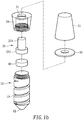
- a dental implant constructed according to a first preferred embodiment of the present invention is shown in Figs. 1a and 1b , which has a substantially cylindrical solid base member 10; an abutment 20; an implant-abutment junction (IAJ) portion 30 at a top end of said base member 10 to retain said abutment 20 to said base member 10, so that said abutment 20 is able to move within a predetermined distance alone an axial direction of said base member 10.
- IAJ implant-abutment junction
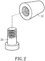
- Said abutment 20 has a receiving part 21 for receiving a dental prosthesis and a connecting part 22, wherein said IAJ portion 30 has an axial hole 31 and said connecting part 22 of said abutment has a cylindrical rod portion 221 having a diameter corresponding said axial hole 31 and an enlarged end 222 extending from said cylindrical rod portion, wherein said cylindrical rod portion 221 is slidably received in said axial hole 31 of said IAJ portion 30 with said enlarged end 222 protruding from the bottom end of said axial hole 31 and the top end of said cylindrical rod portion protruding from the top end of said axial hole 31.
- Said IAJ portion 30 is a separate part and threadedly connected to said top end of said base member 10, preventing said abutment 20 from escaping said IAJ portion 30.
- a first cushion 40 which is a round plate made of elastomer and is put on the top end of the base member 10 before said IAJ portion 30 is threadedly connected to said top end of said base member 10.
- the first cushion 40 is sandwiched between said enlarged end 222 of said connecting part 22 of said abutment 20 and the top end of said base member 10 for providing a resistance force when said abutment 20 is pressed to move relatively toward said base member 10 and providing a bouncing back force when said abutment 20 is released from said pressing
- Said substantially cylindrical solid base member 10 is provided with a sharpened end 12 opposite to said IAJ portion 30, and provided with threads 1 3 on an outer surface thereof.
- the dental implant further comprises a second cushion 50 which is a ring made of an elastomer, and is mounted on the cylindrical rod portion 221 of said connecting part 22 and is sandwiched between said IAJ portion 30 and said receiving part 21 of said abutment 20.
- the cylindrical rod portion 221 of said connecting part 22 is plugged into a corresponding recess at a bottom of said receiving part 21 of said abutment 20.
- said connecting part 22 of said abutment 20 is threadedly connected to said receiving part 21 of said abutment 20 as shown in Fig. 2 .
- a dental implant constructed according to an embodiment, as shown in Figure 3 which is similar to the first preferred embodiment shown in Figs. 1a and 1b except that the abutment 20 and the IAJ portion 30.
- the embodiment as shown in Figure 3 is helpful for understanding the present invention.
- said abutment 20 has a receiving part 21 and a connecting part 22 integrally extending from a bottom of said receiving part 21.
- the connecting part 22 has a cylindrical rod portion 221 and an enlarged threaded end 222 extending from said cylindrical rod portion 221.
- the first cushion 40 is mounted similarly to that shown in Figs. 1a and 1b .
- the second cushion 50 which is a ring made of an elastomer is mounted on the cylindrical rod portion 221 from the enlarged threaded end 222 of the connecting part 22.
- the IAJ portion 30 has an axial hole 31 having a threaded inner wall portion 311 corresponding to said an enlarged threaded end 222 and a smooth inner wall portion 312 following the threaded inner wall portion 311 having a diameter slightly larger than that of said enlarged threaded end 222, wherein said enlarged threaded end 222 is threaded through the threaded inner wall portion 311 and into the smooth inner wall portion 312 of said axial hole 31.
- the dental implant shown in Fig. 4 is similar to the first preferred embodiment shown in Figs. 1a and 1b except that the IAJ portion 30 is connected to the based member 10 by using an interference fit connection in Fig. 3 instead of threading in Figs. 1a and 1b .
- the embodiment as shown in Figure 5 is helpful for understanding the present invention.
- the dental implant shown in Fig. 5 is similar to the first preferred embodiment shown in Figs. 1a and 1b except the IAJ portion 30.
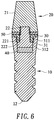
- the IAJ portion 30 is provided with a threaded annular portion
- the base member 10 is provided with an axial hole 31 at a top end thereof.
- the axial hole 31 has a threaded inner wall portion 311 corresponding to said threaded annular portion and a smooth inner wall portion 312 following the threaded inner wall portion 311 having a diameter slightly larger than that of the enlarged end 222.
- the IAJ portion 30 is threadedly connected to the top end of the base member 1 0 through said threaded annular portion of the IAJ portion 30 and the threaded inner wall portion 311 of said axial hole 31.
- the first cushion 40 and the second cushion 50 are mounted similarly to those shown in Figs. 1a and 1b .
- the dental implant shown in Fig. 6 is similar to the embodiment shown in Fig. 5 except that the receiving part 21 is connected to the connecting part 22 of the abutment 20 via threading in Fig. 6 instead of the interference fit connection shown in Fig. 5 or in Figs. 1a and 1b .
- the embodiment as shown in Figure 6 is helpful for understanding the present invention.
- the dental implant shown in Fig. 7 is similar to the embodiment shown in Fig. 5 except that the IAJ portion 30 is connected to the based member 10 by using an interference fit connection in Fig. 7 instead of threading in Fig. 5 .
- the dental implant as shown in Figure 7 is helpful for understanding the present invention.
- the dental implant as shown in Figure 8 is helpful for understanding the present invention.
- the dental implant shown in Fig. 8 is similar to the embodiment shown in Fig. 3 .
- said abutment 20 has a receiving part 21 and a connecting part 22 integrally extending from a bottom of said receiving part 21.
- the connecting part 22 has a cylindrical rod portion 221 and an enlarged end 222 extending from said cylindrical rod portion 221.
- the second cushion 50 which is a ring made of an elastomer is mounted on the cylindrical rod portion 221 from the enlarged end 222 of the connecting part 22, and then said connecting part 22 of said abutment 20 is forced to insert into a C-shaped or O-shaped buckle 60, so that said C-shaped or O-shaped buckle 60 is mounted on the cylindrical rod portion 221, and the second cushion 50 is sandwiched between the receiving part 21 and the C-shaped or O-shaped buckle 60.
- the base member 10 has a sharpened end and a smooth outer surface.
- the IAJ portion 30 has an axial hole 31 having a diameter slightly smaller than the outer diameter of the C-shaped or O-shaped buckle 60.
- a first cushion 40 which is a round plate made of an elastomer is placed on a bottom surface of the axial hole 31, and then the abutment 20 together with the second cushion 50 and the C-shaped or O-shaped buckle 60 mounted thereon are forced to insert into the axial hole 31 of the IAJ portion 30 of the base member 10, until the C-shaped or O-shaped buckle 60 is elastically detained by the inner wall portion 321 of the axial hole 31 of said IAJ portion 30, whereby the first cushion 40 is sandwiched between said enlarged end 222 of said connecting part 22 of said abutment 20 and said based member 10, and the second cushion 50 is sandwiched between said IAJ portion 30 of the based member 10 and the receiving part 21 of said abutment 20.
- the C-shaped or O-shaped buckle 60 is preferably made from a highly elastic material, more preferably from a highly elastic (high modulus) metallic material, so that when the buckle is bent to facilitate installation or removal of the buckle, little plastic (permanent) deformation occurs.
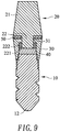
- the dental implant shown in Fig. 9 is similar to the embodiment shown in Figs. 1a and 1b except the abutment 20.
- the connecting part 22 of the abutment 20 has a cylindrical rod portion 221 and a separate enlarged end 222, wherein the separate enlarged end 222 is placed on top of the first cushion 40 before the IAJ portion 30 is threadedly connected to the top end of the base member 10, and then the cylindrical rod portion 221 is inserted into the axial hole 31 of the IAJ portion 30 and is forced to connect to the separate enlarged end 222 via interference fit connection.
- the dental implant shown in Figure 9 is executed in accordance with the present invention.
- a single-cushioned dental implant and a double-cushioned dental implant were manufactured (by a 5-axis precision machining system) from grade-4 commercially pure titanium except the cushions which were hand-made from an elastomeric material (Silagum®, DMG Chemisch-Pharmazeutician Fabrik GmbH , Hamburg, Germany).
- the double-cushioned dental implant has a construction shown in Figs. 1a and 1b .
- the single-cushioned dental implant is the same as the double-cushioned dental implant except that it does not have the second cushion 50.
- a servo-hydraulic type testing system (EH F-EG, Shimadzu Co., Tokyo, Japan) was used for the fatigue testing according to the ISO 14801 -Dentistry- Implants-Dynamic fatigue test for endosseous dental implants method. 300 N was used as the loading force (F). The load varied sinusoidally between a nominal peak value and 10% of this value. 10 Hz was used as the loading frequency (f). (The specified value of ISO 14801 is no more than 15 Hz) The testing was conducted in air between 20 and 25°C.
Landscapes
- Health & Medical Sciences (AREA)
- Oral & Maxillofacial Surgery (AREA)
- Orthopedic Medicine & Surgery (AREA)
- Dentistry (AREA)
- Epidemiology (AREA)
- Life Sciences & Earth Sciences (AREA)
- Animal Behavior & Ethology (AREA)
- General Health & Medical Sciences (AREA)
- Public Health (AREA)
- Veterinary Medicine (AREA)
- Dental Prosthetics (AREA)
Applications Claiming Priority (2)
| Application Number | Priority Date | Filing Date | Title |
|---|---|---|---|
| US201361898560P | 2013-11-01 | 2013-11-01 | |
| PCT/US2014/063364 WO2015066438A1 (en) | 2013-11-01 | 2014-10-31 | Double-cushioned dental implant |
Publications (3)
| Publication Number | Publication Date |
|---|---|
| EP3062732A1 EP3062732A1 (en) | 2016-09-07 |
| EP3062732A4 EP3062732A4 (en) | 2016-11-09 |
| EP3062732B1 true EP3062732B1 (en) | 2018-07-18 |
Family
ID=53005173
Family Applications (1)
| Application Number | Title | Priority Date | Filing Date |
|---|---|---|---|
| EP14858170.5A Active EP3062732B1 (en) | 2013-11-01 | 2014-10-31 | Double-cushioned dental implant |
Country Status (7)
| Country | Link |
|---|---|
| US (2) | US9848961B2 (zh) |
| EP (1) | EP3062732B1 (zh) |
| JP (1) | JP6397928B2 (zh) |
| KR (1) | KR102203291B1 (zh) |
| CN (1) | CN105792772B (zh) |
| TW (1) | TWI611796B (zh) |
| WO (1) | WO2015066438A1 (zh) |
Families Citing this family (7)
| Publication number | Priority date | Publication date | Assignee | Title |
|---|---|---|---|---|
| KR101719402B1 (ko) * | 2014-12-15 | 2017-03-23 | 장재우 | 치과 임플란트 유닛 및 그 제조 방법 |
| ES2870992T3 (es) * | 2015-06-08 | 2021-10-28 | Biomet 3I Llc | Sistema de restauración dental |
| BR112017025452B1 (pt) | 2015-07-24 | 2021-05-04 | Nobel Biocare Services Ag | adaptador para ligar um primeiro componente dentário a um segundo componente dentário, e conjunto dentário que compreende o adaptador |
| CN109394361A (zh) * | 2017-08-15 | 2019-03-01 | 捷钛生医股份有限公司 | 用于种植牙的缓冲件 |
| KR102318794B1 (ko) * | 2019-07-01 | 2021-10-27 | 하명헌 | 임플란트용 어버트먼트 |
| KR102048180B1 (ko) * | 2019-08-14 | 2019-11-22 | 정재석 | 개선된 고정 구조 및 완충 구조를 갖는 인공치아용 임플란트 |
| KR102107991B1 (ko) * | 2019-10-18 | 2020-05-07 | 채희진 | 틀니체결용 임플란트 및 이를 이용한 틀니 제조방법 |
Family Cites Families (31)
| Publication number | Priority date | Publication date | Assignee | Title |
|---|---|---|---|---|
| NO162102C (no) * | 1983-05-17 | 1989-11-08 | Alberto Arruga Artal | Tann-implanteringsanordning. |
| EP0231400A1 (en) * | 1985-11-11 | 1987-08-12 | Peter Gabriel Mozsary | Osteocorrective dentoalveolar implant system |
| SE450334B (sv) * | 1985-09-16 | 1987-06-22 | Dan Lundgren | Kopplingselement till orala proteser innefattande en hettformad matris |
| DE3615733A1 (de) * | 1986-05-09 | 1987-11-12 | Leitz Ernst Gmbh | Zahnwurzel-implantat hoher dauerschwingfestigkeit |
| JPH0247213B2 (ja) * | 1986-06-30 | 1990-10-18 | Noryuki Nagai | Inpurantogishi |
| DE3731265A1 (de) * | 1987-09-17 | 1989-03-30 | Richter Ernst Juergen Dr | Kronen-befestigungsvorrichtung fuer ein in einen kiefer einzusetzendes implantat |
| IT1218169B (it) * | 1987-10-08 | 1990-04-12 | Aldo Scatena | Moncone destinato ad essere fissato sulla parte endossea di un impianto dentario |
| AT388096B (de) * | 1988-01-04 | 1989-04-25 | Metall Und Kunststoffwaren Erz | Implantat zur befestigung von zahnprothesen |
| US5040982A (en) * | 1990-06-28 | 1991-08-20 | Stefan Dogar Sorin | Dental implant and conversion assembly |
| JPH04200540A (ja) * | 1990-11-30 | 1992-07-21 | Koki Bussan Kk | 人工歯根 |
| JPH05277134A (ja) * | 1992-04-03 | 1993-10-26 | Lion Corp | 人工歯根 |
| EP0629384B1 (de) | 1993-06-14 | 1996-11-27 | Institut Straumann Ag | Vorrichtung zur Befestigung eines künstlichen Zahnersatzes an einem Kieferknochen |
| JPH078508A (ja) * | 1993-06-24 | 1995-01-13 | Lion Corp | 人工歯根 |
| US5417570A (en) * | 1994-01-03 | 1995-05-23 | Zest Anchors, Inc. | Dental anchor assembly |
| US5556280A (en) | 1994-05-31 | 1996-09-17 | Pelak; Mark S. | Method and apparatus for appliance mounting |
| TW353611B (en) * | 1997-09-11 | 1999-03-01 | Yu-Min Pan | Artificial tooth implant with buffer device |
| BR9909601B1 (pt) * | 1998-04-08 | 2009-08-11 | implante dentário simples intra-ósseo. | |
| IT1314729B1 (it) * | 2000-05-10 | 2003-01-03 | Physioplant S R L | Dispositivo protesico per impianti dentali intraossei |
| US6939135B2 (en) * | 2002-06-03 | 2005-09-06 | Schubert L. Sapian | Growth factor releasing biofunctional dental implant |
| US7214063B2 (en) * | 2004-07-29 | 2007-05-08 | Yechiel Cohen | Implant system particularly useful for fixing dental prostheses to bone |
| US20070005042A1 (en) * | 2005-06-30 | 2007-01-04 | Alza Corporation | Programmable Intraosseous Drug Delivery System |
| US20090317769A1 (en) | 2006-11-14 | 2009-12-24 | Urdaneta Rainier A | Resilient coping for immediate loading of dental implants |
| US7704076B2 (en) * | 2006-12-20 | 2010-04-27 | Zest Ip Holdings Llc | Dental attachment assembly and method |
| US20080241790A1 (en) * | 2007-03-30 | 2008-10-02 | Gittleman Neal B | CIP of Expanding Ball Lock Oral Prosthesis Alignment Apparatus |
| US20080261174A1 (en) * | 2007-04-23 | 2008-10-23 | Gittleman Neal B | Expanding Ball Lock Oral Prosthesis Alignment Apparatus |
| US8246870B2 (en) | 2009-06-01 | 2012-08-21 | Layton Grant H | Dental implant system and method of use |
| EP2609883B1 (en) * | 2009-08-12 | 2016-11-02 | Biedermann Technologies GmbH & Co. KG | A receiving part for receiving a rod for coupling the rod to a bone anchoring element |
| TWI487507B (zh) * | 2012-05-07 | 2015-06-11 | Univ Nat Cheng Kung | 具有緩衝的牙科植入物 |
| KR101443827B1 (ko) * | 2014-02-18 | 2014-09-26 | 현기봉 | 비침습식 혈액 측정장치 |
| KR101570615B1 (ko) * | 2014-09-04 | 2015-11-19 | 허덕수 | 임플란트용 픽스츄어 리무버 |
| WO2016154453A1 (en) * | 2015-03-24 | 2016-09-29 | University Of Connecticut | Artificial salivary gland |
-
2014
- 2014-10-28 TW TW103137257A patent/TWI611796B/zh active
- 2014-10-31 CN CN201480059622.XA patent/CN105792772B/zh active Active
- 2014-10-31 WO PCT/US2014/063364 patent/WO2015066438A1/en active Application Filing
- 2014-10-31 EP EP14858170.5A patent/EP3062732B1/en active Active
- 2014-10-31 JP JP2016552252A patent/JP6397928B2/ja active Active
- 2014-10-31 US US15/032,680 patent/US9848961B2/en active Active
- 2014-10-31 KR KR1020167012072A patent/KR102203291B1/ko active IP Right Grant
-
2017
- 2017-11-20 US US15/818,054 patent/US10111735B2/en active Active
Non-Patent Citations (1)
| Title |
|---|
| None * |
Also Published As
| Publication number | Publication date |
|---|---|
| JP6397928B2 (ja) | 2018-09-26 |
| EP3062732A4 (en) | 2016-11-09 |
| KR20160082511A (ko) | 2016-07-08 |
| US10111735B2 (en) | 2018-10-30 |
| EP3062732A1 (en) | 2016-09-07 |
| US20180071059A1 (en) | 2018-03-15 |
| WO2015066438A1 (en) | 2015-05-07 |
| KR102203291B1 (ko) | 2021-01-14 |
| US20160262855A1 (en) | 2016-09-15 |
| CN105792772B (zh) | 2019-05-21 |
| TWI611796B (zh) | 2018-01-21 |
| US9848961B2 (en) | 2017-12-26 |
| JP2016535653A (ja) | 2016-11-17 |
| CN105792772A (zh) | 2016-07-20 |
| TW201517879A (zh) | 2015-05-16 |
Similar Documents
| Publication | Publication Date | Title |
|---|---|---|
| EP3062732B1 (en) | Double-cushioned dental implant | |
| US10271928B2 (en) | Dental implant with cushion | |
| US9522053B2 (en) | Dental implant assembly for uniform distribution of occlusal forces | |
| KR101592141B1 (ko) | 임플란트 시술용 픽스쳐 | |
| EP3040047A1 (en) | Attachment for plate denture | |
| KR102321570B1 (ko) | 치과용 임플란트 | |
| KR20150089419A (ko) | 치과용 임플란트의 완충부재 및 이를 구비하는 치과용 임플란트 | |
| US8926326B2 (en) | Denture retention system | |
| KR101380919B1 (ko) | 지대주 및 이를 포함하는 치아 임플란트 장치 | |
| WO2011069226A1 (en) | Apparatus, method, and system for holding a denture | |
| KR101597151B1 (ko) | 치과용 임플란트 | |
| KR101648742B1 (ko) | 어버트먼트 및 어버트먼트 조립체 | |
| KR20200020025A (ko) | 임플란트용 탄성 어버트먼트 | |
| US20180055606A1 (en) | Abutment assembly and manufacturing method thereof | |
| US20220273402A1 (en) | Implant abutment | |
| KR102658870B1 (ko) | 3중 구조를 갖는 치과용 어버트먼트 및 이를 구비한 치과용 임플란트 시스템 | |
| EP4295810A1 (en) | Dental implant attachment for removable dentures | |
| KR20230022004A (ko) | 임플란트 유닛 | |
| CN204468310U (zh) | 一种嵌固型植牙构件 | |
| KR101296740B1 (ko) | 넌-서브머지드 타입 임플란트용 지대주 | |
| KR20160139666A (ko) | 임플란트 시술용 픽스쳐 | |
| TW201429451A (zh) | 人工牙植體系統 |
Legal Events
| Date | Code | Title | Description |
|---|---|---|---|
| PUAI | Public reference made under article 153(3) epc to a published international application that has entered the european phase |
Free format text: ORIGINAL CODE: 0009012 |
|
| 17P | Request for examination filed |
Effective date: 20160429 |
|
| AK | Designated contracting states |
Kind code of ref document: A1 Designated state(s): AL AT BE BG CH CY CZ DE DK EE ES FI FR GB GR HR HU IE IS IT LI LT LU LV MC MK MT NL NO PL PT RO RS SE SI SK SM TR |
|
| AX | Request for extension of the european patent |
Extension state: BA ME |
|
| A4 | Supplementary search report drawn up and despatched |
Effective date: 20161010 |
|
| RIC1 | Information provided on ipc code assigned before grant |
Ipc: A61C 8/00 20060101AFI20161004BHEP Ipc: A61C 13/263 20060101ALI20161004BHEP |
|
| DAX | Request for extension of the european patent (deleted) | ||
| GRAP | Despatch of communication of intention to grant a patent |
Free format text: ORIGINAL CODE: EPIDOSNIGR1 |
|
| INTG | Intention to grant announced |
Effective date: 20171116 |
|
| RIN1 | Information on inventor provided before grant (corrected) |
Inventor name: CHEN, YEN-CHUN Inventor name: LIN, JIIN-HUEY CHERN Inventor name: JU, CHIEN-PING |
|
| GRAJ | Information related to disapproval of communication of intention to grant by the applicant or resumption of examination proceedings by the epo deleted |
Free format text: ORIGINAL CODE: EPIDOSDIGR1 |
|
| GRAP | Despatch of communication of intention to grant a patent |
Free format text: ORIGINAL CODE: EPIDOSNIGR1 |
|
| INTC | Intention to grant announced (deleted) | ||
| INTG | Intention to grant announced |
Effective date: 20180315 |
|
| GRAS | Grant fee paid |
Free format text: ORIGINAL CODE: EPIDOSNIGR3 |
|
| GRAA | (expected) grant |
Free format text: ORIGINAL CODE: 0009210 |
|
| AK | Designated contracting states |
Kind code of ref document: B1 Designated state(s): AL AT BE BG CH CY CZ DE DK EE ES FI FR GB GR HR HU IE IS IT LI LT LU LV MC MK MT NL NO PL PT RO RS SE SI SK SM TR |
|
| REG | Reference to a national code |
Ref country code: GB Ref legal event code: FG4D |
|
| REG | Reference to a national code |
Ref country code: CH Ref legal event code: EP Ref country code: CH Ref legal event code: NV Representative=s name: BOVARD AG PATENT- UND MARKENANWAELTE, CH |
|
| REG | Reference to a national code |
Ref country code: IE Ref legal event code: FG4D |
|
| REG | Reference to a national code |
Ref country code: AT Ref legal event code: REF Ref document number: 1018543 Country of ref document: AT Kind code of ref document: T Effective date: 20180815 |
|
| REG | Reference to a national code |
Ref country code: DE Ref legal event code: R096 Ref document number: 602014028908 Country of ref document: DE |
|
| REG | Reference to a national code |
Ref country code: FR Ref legal event code: PLFP Year of fee payment: 5 |
|
| REG | Reference to a national code |
Ref country code: NL Ref legal event code: MP Effective date: 20180718 |
|
| REG | Reference to a national code |
Ref country code: LT Ref legal event code: MG4D |
|
| REG | Reference to a national code |
Ref country code: AT Ref legal event code: MK05 Ref document number: 1018543 Country of ref document: AT Kind code of ref document: T Effective date: 20180718 |
|
| PG25 | Lapsed in a contracting state [announced via postgrant information from national office to epo] |
Ref country code: NL Free format text: LAPSE BECAUSE OF FAILURE TO SUBMIT A TRANSLATION OF THE DESCRIPTION OR TO PAY THE FEE WITHIN THE PRESCRIBED TIME-LIMIT Effective date: 20180718 |
|
| PG25 | Lapsed in a contracting state [announced via postgrant information from national office to epo] |
Ref country code: FI Free format text: LAPSE BECAUSE OF FAILURE TO SUBMIT A TRANSLATION OF THE DESCRIPTION OR TO PAY THE FEE WITHIN THE PRESCRIBED TIME-LIMIT Effective date: 20180718 Ref country code: LT Free format text: LAPSE BECAUSE OF FAILURE TO SUBMIT A TRANSLATION OF THE DESCRIPTION OR TO PAY THE FEE WITHIN THE PRESCRIBED TIME-LIMIT Effective date: 20180718 Ref country code: IS Free format text: LAPSE BECAUSE OF FAILURE TO SUBMIT A TRANSLATION OF THE DESCRIPTION OR TO PAY THE FEE WITHIN THE PRESCRIBED TIME-LIMIT Effective date: 20181118 Ref country code: BG Free format text: LAPSE BECAUSE OF FAILURE TO SUBMIT A TRANSLATION OF THE DESCRIPTION OR TO PAY THE FEE WITHIN THE PRESCRIBED TIME-LIMIT Effective date: 20181018 Ref country code: AT Free format text: LAPSE BECAUSE OF FAILURE TO SUBMIT A TRANSLATION OF THE DESCRIPTION OR TO PAY THE FEE WITHIN THE PRESCRIBED TIME-LIMIT Effective date: 20180718 Ref country code: NO Free format text: LAPSE BECAUSE OF FAILURE TO SUBMIT A TRANSLATION OF THE DESCRIPTION OR TO PAY THE FEE WITHIN THE PRESCRIBED TIME-LIMIT Effective date: 20181018 Ref country code: GR Free format text: LAPSE BECAUSE OF FAILURE TO SUBMIT A TRANSLATION OF THE DESCRIPTION OR TO PAY THE FEE WITHIN THE PRESCRIBED TIME-LIMIT Effective date: 20181019 Ref country code: RS Free format text: LAPSE BECAUSE OF FAILURE TO SUBMIT A TRANSLATION OF THE DESCRIPTION OR TO PAY THE FEE WITHIN THE PRESCRIBED TIME-LIMIT Effective date: 20180718 Ref country code: PL Free format text: LAPSE BECAUSE OF FAILURE TO SUBMIT A TRANSLATION OF THE DESCRIPTION OR TO PAY THE FEE WITHIN THE PRESCRIBED TIME-LIMIT Effective date: 20180718 Ref country code: SE Free format text: LAPSE BECAUSE OF FAILURE TO SUBMIT A TRANSLATION OF THE DESCRIPTION OR TO PAY THE FEE WITHIN THE PRESCRIBED TIME-LIMIT Effective date: 20180718 |
|
| PG25 | Lapsed in a contracting state [announced via postgrant information from national office to epo] |
Ref country code: LV Free format text: LAPSE BECAUSE OF FAILURE TO SUBMIT A TRANSLATION OF THE DESCRIPTION OR TO PAY THE FEE WITHIN THE PRESCRIBED TIME-LIMIT Effective date: 20180718 Ref country code: AL Free format text: LAPSE BECAUSE OF FAILURE TO SUBMIT A TRANSLATION OF THE DESCRIPTION OR TO PAY THE FEE WITHIN THE PRESCRIBED TIME-LIMIT Effective date: 20180718 Ref country code: HR Free format text: LAPSE BECAUSE OF FAILURE TO SUBMIT A TRANSLATION OF THE DESCRIPTION OR TO PAY THE FEE WITHIN THE PRESCRIBED TIME-LIMIT Effective date: 20180718 |
|
| REG | Reference to a national code |
Ref country code: DE Ref legal event code: R097 Ref document number: 602014028908 Country of ref document: DE |
|
| PG25 | Lapsed in a contracting state [announced via postgrant information from national office to epo] |
Ref country code: ES Free format text: LAPSE BECAUSE OF FAILURE TO SUBMIT A TRANSLATION OF THE DESCRIPTION OR TO PAY THE FEE WITHIN THE PRESCRIBED TIME-LIMIT Effective date: 20180718 Ref country code: EE Free format text: LAPSE BECAUSE OF FAILURE TO SUBMIT A TRANSLATION OF THE DESCRIPTION OR TO PAY THE FEE WITHIN THE PRESCRIBED TIME-LIMIT Effective date: 20180718 Ref country code: IT Free format text: LAPSE BECAUSE OF FAILURE TO SUBMIT A TRANSLATION OF THE DESCRIPTION OR TO PAY THE FEE WITHIN THE PRESCRIBED TIME-LIMIT Effective date: 20180718 Ref country code: RO Free format text: LAPSE BECAUSE OF FAILURE TO SUBMIT A TRANSLATION OF THE DESCRIPTION OR TO PAY THE FEE WITHIN THE PRESCRIBED TIME-LIMIT Effective date: 20180718 Ref country code: CZ Free format text: LAPSE BECAUSE OF FAILURE TO SUBMIT A TRANSLATION OF THE DESCRIPTION OR TO PAY THE FEE WITHIN THE PRESCRIBED TIME-LIMIT Effective date: 20180718 |
|
| PLBE | No opposition filed within time limit |
Free format text: ORIGINAL CODE: 0009261 |
|
| STAA | Information on the status of an ep patent application or granted ep patent |
Free format text: STATUS: NO OPPOSITION FILED WITHIN TIME LIMIT |
|
| PG25 | Lapsed in a contracting state [announced via postgrant information from national office to epo] |
Ref country code: DK Free format text: LAPSE BECAUSE OF FAILURE TO SUBMIT A TRANSLATION OF THE DESCRIPTION OR TO PAY THE FEE WITHIN THE PRESCRIBED TIME-LIMIT Effective date: 20180718 Ref country code: SM Free format text: LAPSE BECAUSE OF FAILURE TO SUBMIT A TRANSLATION OF THE DESCRIPTION OR TO PAY THE FEE WITHIN THE PRESCRIBED TIME-LIMIT Effective date: 20180718 Ref country code: SK Free format text: LAPSE BECAUSE OF FAILURE TO SUBMIT A TRANSLATION OF THE DESCRIPTION OR TO PAY THE FEE WITHIN THE PRESCRIBED TIME-LIMIT Effective date: 20180718 |
|
| 26N | No opposition filed |
Effective date: 20190423 |
|
| REG | Reference to a national code |
Ref country code: BE Ref legal event code: MM Effective date: 20181031 |
|
| PG25 | Lapsed in a contracting state [announced via postgrant information from national office to epo] |
Ref country code: MC Free format text: LAPSE BECAUSE OF FAILURE TO SUBMIT A TRANSLATION OF THE DESCRIPTION OR TO PAY THE FEE WITHIN THE PRESCRIBED TIME-LIMIT Effective date: 20180718 Ref country code: LU Free format text: LAPSE BECAUSE OF NON-PAYMENT OF DUE FEES Effective date: 20181031 |
|
| PG25 | Lapsed in a contracting state [announced via postgrant information from national office to epo] |
Ref country code: SI Free format text: LAPSE BECAUSE OF FAILURE TO SUBMIT A TRANSLATION OF THE DESCRIPTION OR TO PAY THE FEE WITHIN THE PRESCRIBED TIME-LIMIT Effective date: 20180718 Ref country code: BE Free format text: LAPSE BECAUSE OF NON-PAYMENT OF DUE FEES Effective date: 20181031 |
|
| PG25 | Lapsed in a contracting state [announced via postgrant information from national office to epo] |
Ref country code: MT Free format text: LAPSE BECAUSE OF NON-PAYMENT OF DUE FEES Effective date: 20181031 |
|
| PG25 | Lapsed in a contracting state [announced via postgrant information from national office to epo] |
Ref country code: TR Free format text: LAPSE BECAUSE OF FAILURE TO SUBMIT A TRANSLATION OF THE DESCRIPTION OR TO PAY THE FEE WITHIN THE PRESCRIBED TIME-LIMIT Effective date: 20180718 |
|
| PG25 | Lapsed in a contracting state [announced via postgrant information from national office to epo] |
Ref country code: PT Free format text: LAPSE BECAUSE OF FAILURE TO SUBMIT A TRANSLATION OF THE DESCRIPTION OR TO PAY THE FEE WITHIN THE PRESCRIBED TIME-LIMIT Effective date: 20180718 |
|
| PG25 | Lapsed in a contracting state [announced via postgrant information from national office to epo] |
Ref country code: HU Free format text: LAPSE BECAUSE OF FAILURE TO SUBMIT A TRANSLATION OF THE DESCRIPTION OR TO PAY THE FEE WITHIN THE PRESCRIBED TIME-LIMIT; INVALID AB INITIO Effective date: 20141031 Ref country code: CY Free format text: LAPSE BECAUSE OF FAILURE TO SUBMIT A TRANSLATION OF THE DESCRIPTION OR TO PAY THE FEE WITHIN THE PRESCRIBED TIME-LIMIT Effective date: 20180718 Ref country code: MK Free format text: LAPSE BECAUSE OF NON-PAYMENT OF DUE FEES Effective date: 20180718 |
|
| REG | Reference to a national code |
Ref country code: DE Ref legal event code: R081 Ref document number: 602014028908 Country of ref document: DE Owner name: JOY MEDICAL DEVICES CORP., TW Free format text: FORMER OWNER: JTI BIOMED CORP., TAINAN CITY, TW Ref country code: DE Ref legal event code: R082 Ref document number: 602014028908 Country of ref document: DE Representative=s name: GRUENECKER PATENT- UND RECHTSANWAELTE PARTG MB, DE |
|
| REG | Reference to a national code |
Ref country code: CH Ref legal event code: PFUS Owner name: JOY MEDICAL DEVICES CORPORATION, TW Free format text: FORMER OWNER: JTI BIOMED CORP., TW |
|
| REG | Reference to a national code |
Ref country code: GB Ref legal event code: 732E Free format text: REGISTERED BETWEEN 20200917 AND 20200923 |
|
| PGFP | Annual fee paid to national office [announced via postgrant information from national office to epo] |
Ref country code: GB Payment date: 20231027 Year of fee payment: 10 |
|
| PGFP | Annual fee paid to national office [announced via postgrant information from national office to epo] |
Ref country code: IE Payment date: 20231027 Year of fee payment: 10 Ref country code: FR Payment date: 20231027 Year of fee payment: 10 Ref country code: DE Payment date: 20231026 Year of fee payment: 10 Ref country code: CH Payment date: 20231102 Year of fee payment: 10 |